workshop manual tbg 620/tbg 620k - powerplant … work shop manual.pdf · workshop manual tbg...
TRANSCRIPT
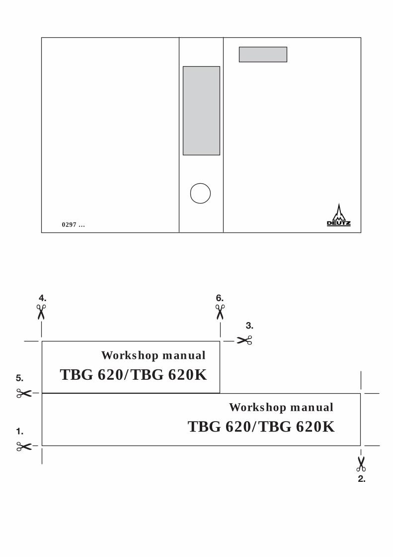
0297 …
✂5.
✂1.
✂
3.
✂
✂
4. 6.
✂
2.
Workshop manual
TBG 620/TBG 620K
Workshop manual
TBG 620/TBG 620K


0299 6277 en
Engine manufacturer:
Motoren-Werke Mannheim AG(DEUTZ MWM)Carl-Benz-Str. 5D-68167 Mannheim
Tel. (06 21) 3 84-0Tx. 462341Fax (06 21) 3 84-83 86
Workshop manual
TBG 620/TBG 620K
We reserve the right to make technical alterations to the drawingsand particulars in this documentation package, if this should be-come necessary to improve the engines. Reprints and duplication ofany kind, either in whole or in part, require our written permission.
Engine Number:
Please enter your engine number here. This will help us to serve youbetter in questions of repairs, spare parts and after-sales servicegenerally.

Page II 0299 3923-0122 0997
DEUTZ MWMTBG 620/TBG 620K
Imprint:DEUTZ AGService-TechnikServicedokumentationDeutz-Mülheimer Straße 147–149D-51057 CologneTel.: (+49 2 21) 8 22-0Fax: (+49 2 21) 8 22-53 58http://www.deutz.de
Printed in GermanyAll rights reserved(1) 0997
Ordering No. 0299 6277 en
This documentation is intended for the following engine.
● Engine type:
● Application:
● System name:
● Rating: kW
● Speed: / min
● Commissioning on: 19
Please enter the relevant data. This will make it easier for us to help you in questions involving repairs,spare parts and after-sales service in general.
This documentation package is to be presented to the Service Partner responsible every time a servicejob is carried out.
0997 0299 3235-0199 Page III
DEUTZ MWMEngines
● Please read all the information contained in this manual, and follow the instructions carefully. You will avoidaccidents, retain the manufacturer’s warranty, and will be able to use a fully functional and operationalengine.
● This engine has been built solely for the purpose appropriate to the scope of delivery concerned, as definedby the equipment manufacturer (intended use). Any other use shall be construed as not intended. Themanufacturer shall not be liable for any damage resulting therefrom; all risks involved shall be borne solelyby the user.
● The term „intended use“ shall also include compliance with the operating, maintenance and repairconditions specified by the manufacturer. The engine may be used, maintained and repaired only bypersons who are familiar with the work concerned and who have been properly informed of the risksinvolved.
● Make sure that these operating instructions are available to everyone involved in operating, maintaining,and repairing the engine, and that they have all understood the contents.
● Non-compliance with these operating instructions may result in engine malfunctions and even damage orinjury to persons; the manufacturer will accept no liability in such cases.
● Proper maintenance and repair work depends on the availability of all requisite equipment, tools and specialimplements, all of which must be in perfect condition.
● Engine parts like springs, brackets, elastic holding rings, etc., involve increased risk of injury if not handledproperly.
● The relevant accident prevention regulations and other generally recognized rules relating to safetyengineering and health and safety at work must all be complied with.
● Maximized cost-efficiency, reliability and long lifetime are assured only if original parts from DEUTZ AG areused.
● Engine repairs must correspond to the intended use. In the event of modification work, only parts approvedby the manufacturer for the purpose concerned may be used. Unauthorized changes to the engine willpreclude any liability of the manufacturer for resultant damage.
Page IV 0299 3235-0199 0997
DEUTZ MWMEngines
Forword
Dear customer,
The engines of the DEUTZ MWM brand have been developed for a broad spectrum of applications.A comprehensive range of different variants ensures that special requirements can be met for theindividual case involved.
Your engine has been equipped to suit your own particular installation, and accordingly not all of thedevices and components described in these operating instructions will actually be fitted to your engine.
We have endeavoured to present the differences involved as clearly as possible, to make it easier foryou to find the operating and maintenance instructions you need for your own particular engine.
Please read this manual before you start up your engine, and follow the operating and maintenanceinstructions meticulously.
If you have any questions, just get in touch with us, and we will be pleased to answer them for you.
Yours sincerely,DEUTZ AG

0997 0299 3235-0199 Page V
DEUTZ MWMEngines
General
DEUTZ MWM enginesare the culmination of long years filled with research and development work. The in-depth know-howthus acquired, in conjunction with high standards of quality, is your guarantee for engines manufacturedfor long lifetime, high reliability and low fuel consumption. And of course, stringent criteria ofenvironment-friendliness are met as well.
Care and maintenanceare crucial factors in ensuring that your engine satisfactorily meets the requirements involved.Compliance with the specified maintenance intervals and meticulous performance of care andmaintenance work are therefore absolutely essential. Special attention must be paid to any morecritical operating conditions deviating from the norm.
DEUTZ AGIn the event of malfunctions, or if you need spare parts, please contact one of our responsible serviceagencies. Our trained and qualified staff will ensure fast, professional rectification of any damage,using original parts.Original parts from DEUTZ AG have always been manufactured to the very latest state-of-the-art.You will find details of our after-sales service at the end of these operating instructions.
Careful when the engine is running!Carry out maintenance or repair jobs only when the engine is at a standstill. If you remove anyprotective features, fit them back in position after completing your work. Always wear tight-fittingclothing if you are working on the engine while it is running.
SafetyYou will find this symbol next to all safety instructions. Follow these meticulously. Pass on all safetyinstructions to your operating staff as well. In addition, comply with the statutory general safety andaccident prevention regulations applying in your country.
InstructionYou will find this symbol next to instructions of a general nature.Follow these instructions carefully.
AsbestosThe seals and gaskets used in this engine are asbestos-free. Please use the appropriate spareparts for maintenance and repair jobs.

Page VI 0299 3232-0199 0997
DEUTZ MWMEngines and Systems
Quick Introduction
QUICK INTRODUCTION (FOR TRAINED AND QUALIFIED PERSONNEL)
➠
➠
➠
GETTING
STARTED
OPERATING INSTRUCTIONSChap. 1 Advice to users
⇓Chap. 2 Description
⇓Chap. 3 Operation
⇓Chap. 4 Expendables
⇓Chap. 10 Test reports
NORMAL
OPERATION
OPERATING INSTRUCTIONSChap. 3 Operation
⇓Chap. 4 Expendables
MAINTENANCE OPERATING INSTRUCTIONSChap. 1 Advice to users
⇓Chap. 4 Expendables
⇓Chap. 5 Maintenance and
Servicing⇓
Chap. 8 Technical data⇓
Chap. 9 Maintenance work⇓
SPARE PARTS CATALOGUESpare parts
⇓DEUTZ Service

0997 0299 3232-0199 Page VII
DEUTZ MWMEngines and Systems
Quick Introduction
➠
➠
⇓⇓
SERVICING OPERATING INSTRUCTIONSChap. 1 Advice to users
⇓Chap. 5 Maintenance and
Servicing⇓
Chap. 8 Technical data⇓
WORKSHOP MANUALServicing work
⇓SPARE PARTS CATALOGUE
Spare parts⇓
DEUTZ Service
MALFUNCTIONS INOPERATION
OPERATING INSTRUCTIONSChap. 6 Operational disturbances
causes, corrective action⇓
Chap. 8 Technical data⇓
Chap. 10 Test reports
Chap. 9 Maintenance work⇓
SPARE PARTS CATALOGUESpare parts
⇓DEUTZ Service
WORKSHOP MANUALServicing work
⇓SPARE PARTS CATALOGUE
Spare parts⇓
DEUTZ Service
Page VIII 0299 3232-0199 0997
DEUTZ MWMEngines and Systems
This page intentionally left blank.

0997 0299 3920-0122 Page IX
DEUTZ MWM ContentsTBG 620/TBG 620K
0 Introduction
Imprint, foreword, quick introduction, contents
1 Advice to users
1.1 General remarks
1.2 Safety instructions / Accident prevention
1.3 Operating instructions and Workshop manual
1.4 Job cards
1.5 Spare parts
2 Job Cards
2.1 Overviews2.1.1 Arranged alphabetically2.1.2 Arranged by Job Card Numbers2.1.3 Explanation of symbols
2.2 Job Cards arranged by Job Card Numbers
Service

Page X 0299 3920-0122 0997
Contents DEUTZ MWMTBG 620/TBG 620K
Please note:
Operating instructions for DEUTZ MWM TEM System are a separate documentationand has to be ordered separately.

0997 0299 3245-0199 Chapter 1 - Page 1
DEUTZ MWM Advice to usersEngines and Systems
11 Advice to users
1.1 General remarks
1.2 Safety instructions / Accident prevention
1.3 Operating instructions and Workshop manual
1.4 Job cards
1.5 Spare parts

Chapter 1 - Page 2 0299 3245-0199 0997
Advice to users DEUTZ MWMEngines and Systems
1 1 Advice to users
1.1 General remarksThe maintenance and servicing jobs specified in this manual must be carried out punctually and completely.
The maintenance and servicing staff must possess the necessary technical knowledge required for doing theirjobs properly. Any safety and protective features which had to be removed during maintenance and servicingwork must be fitted back in place after completion.
The accident prevention and safety regulations must by always be complied with throughoutall maintenance and servicing work.
Also note the special safety instructions for the various servicing groups which are listedin detail as job cards in the Chapter „Job Cards“ see also Chapter 1.2).
The maintenance and servicing intervals are given in the maintenance and servicing schedule, which alsoprovides information on the jobs required.
The job cards (Chapter 9) give technical instructions on how to actually perform the jobs.
1.2 Safety instructions / Accident preventionFor various servicing groups, detailed safety advice has have been drawn up in the form of job cards;they are listed before the job cards of the respective servicing groups.
The statutory accident prevention regulations have to be complied with (obtainable from professionalassociations or in specialized bookshops). They depend on the installation site, the operating mode andthe expendables and auxiliary materials used.
Special protective arrangements dependent on the particular jobs are indicated and marked in the jobdescription.
In general, the following applies:
● for the personnel:
- Only trained personnel may operate or maintain the engine. Unauthorized persons are notallowed to enter the machine room.
- When the engine is in operation, wear only tight-fitting clothes and ear muffs in the machine room.- Use only professionally qualified staff for repair work.
● for the machine room:
- Ensure sufficient ventilation (do not cover air shafts).- Provide first-aid kit and suitable fire extinguishers and check their contents and serviceability at
regular intervals.- Only store combustible materials in the machine room if they are necessary for the operation of
the system.- Smoking and open flames are not allowed in the machine room.
● for operation and maintenance of the engine:
- Only start the engine when all protective devices have been installed and the turning device hasbeen removed. Make sure that there is nobody in the danger area.
- Only carry out any cleaning, maintenance and repair work when the motor is shut down andsecured against starting.

0997 0299 3245-0199 Chapter 1 - Page 3
DEUTZ MWM Advice to usersEngines and Systems
11.3 Operating instructions and Workshop manualIn order to provide a user-specific information structure, the service documentation has been divided into theOperating Instructions and the Workshop Manual.
The Operating Instructions include a general description as well as instructions for all necessary maintenancejobs.
In detail, they contain the following chapters:
0 General remarks, Getting started, Contents
1 Advice for the user
2 Engine description
3 Operating the engine, with- Work routines before initial start-up and after every inspection- Work routines before start-up- Start-up- Operational monitoring- Shutting down the engine- Emergency operation if components fail (if necessary and possible).
4 Instructions for expendables
5 Maintenance and servicing, with- Tools and equipment overview- Maintenance and servicing schedules
6 Operational malfunctions, their causes and how to correct them
7 Engine conservation
8 Technical particulars
9 Job Cards, arranged by Job Card Numbers
10 Sundry other instructions (if not included in the appendix or in separate files)
After-sales service• Global service directory.
The Workshop Manual presopposes knowledge of the contents of the Operating Instructions. This particularlyapplies to the safety instructions. It describes easy repair jobs and emergency measures on components, whichare more elaborate to peform, and require appropriately qualified professional staff.
It contains the following chapters:
0 General remarks, Getting started, Contents
1 Advice for the user
2 Job Cards, arranged by Job Card Numbers
After-sales service• Global service directory.
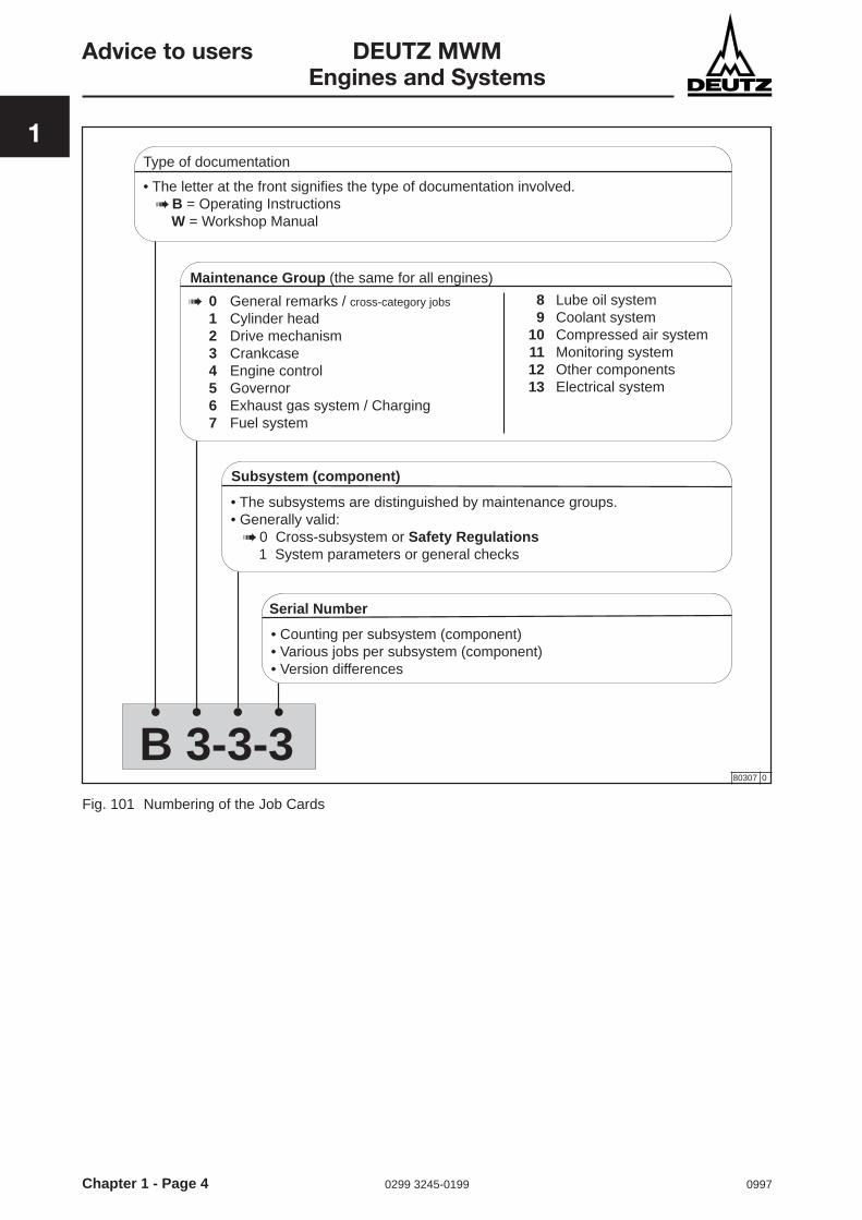
1.4 Job cardsThe Job cards are divided into maintenance Job Cards of Operating instructions , for example B 1-1-1 andservicing Job Cards of the Workshop Manual, for example W 4-5-1.
For the numbering please refer to Fig. 101.
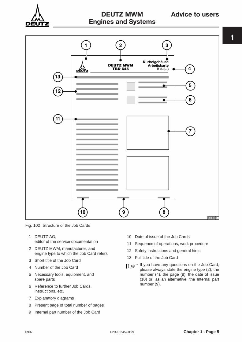
The structure of a Job Card is shown in Fig. 102.
Chapter 1 - Page 4 0299 3245-0199 0997
Advice to users DEUTZ MWMEngines and Systems
1Type of documentation
Subsystem (component)
Serial Number
Maintenance Group (the same for all engines)
• The letter at the front signifies the type of documentation involved. ➠ B = Operating Instructions W = Workshop Manual
• The subsystems are distinguished by maintenance groups.• Generally valid: ➠ 0 Cross-subsystem or Safety Regulations 1 System parameters or general checks
• Counting per subsystem (component)• Various jobs per subsystem (component)• Version differences
➠ 0 General remarks / cross-category jobs
1 Cylinder head2 Drive mechanism3 Crankcase4 Engine control5 Governor6 Exhaust gas system / Charging7 Fuel system
8 Lube oil system9 Coolant system
10 Compressed air system11 Monitoring system12 Other components13 Electrical system
B 3-3-380307 0
Fig. 101 Numbering of the Job Cards
0997 0299 3245-0199 Chapter 1 - Page 5
DEUTZ MWM Advice to usersEngines and Systems
1
80300 1
Fig. 102 Structure of the Job Cards
1 DEUTZ AG,editor of the service documentation
2 DEUTZ MWM, manufacturer, andengine type to which the Job Card refers
3 Short title of the Job Card
4 Number of the Job Card
5 Necessary tools, equipment, andspare parts
6 Reference to further Job Cards,instructions, etc.
7 Explanatory diagrams
8 Present page of total number of pages
9 Internal part number of the Job Card
10 Date of issue of the Job Cards
11 Sequence of operations, work procedure
12 Safety instructions and general hints
13 Full title of the Job Card
If you have any questions on the Job Card,please always state the engine type (2), thenumber (4), the page (8), the date of issue(10) or, as an alternative, the Internal partnumber (9).
Chapter 1 - Page 6 0299 3245-0199 0997
Advice to users DEUTZ MWMEngines and Systems
1 1.5 Spare partsYou will receive spare parts from Messrs. DEUTZ AG.You will find a list of the spare parts in the engine’sspare parts list.
0997 0299 3921-0122 Chapter 2 - Page 1
DEUTZ MWM Job CardsTBG 620/TBG 620K
2
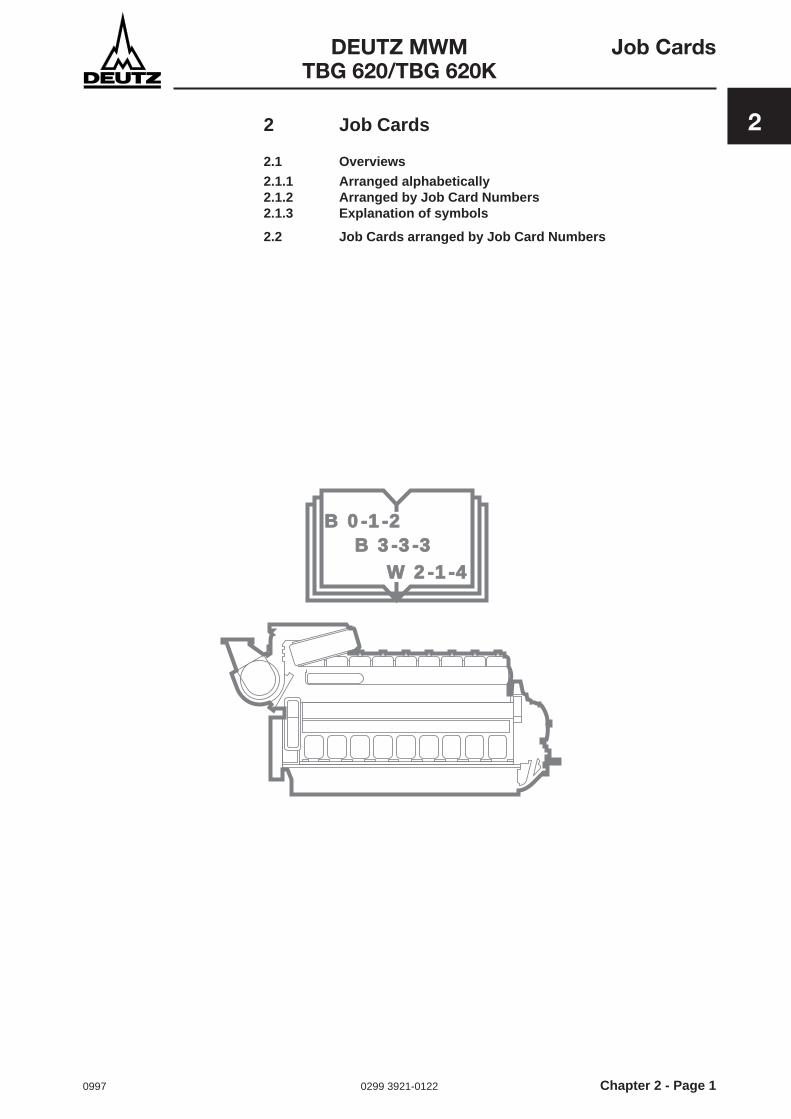
B 0-1-2B 0-1-2B 3-3-3B 3-3-3
W 2-1-4W 2-1-4
2 Job Cards
2.1 Overviews
2.1.1 Arranged alphabetically2.1.2 Arranged by Job Card Numbers2.1.3 Explanation of symbols
2.2 Job Cards arranged by Job Card Numbers

Chapter 2 - Page 2 0299 3921-0122 0997
Job Cards DEUTZ MWMTBG 620/TBG 620K
2 2 Job Cards
2.1 Overviews
2.1.1 Arranged alphabetically
Jobs Job Card
Bearing race (drive end): removing and installing W 2-2-1
Bearing race (free end): removing and installing W 2-2-3
Bearing shells: checking for wear and tear W 2-1-3
Bearing spread: checking W 2-1-1
Camshaft bearings: removing and installing W 4-1-1
Camshaft: installing W 4-5-2
Camshaft: removing and checking W 4-5-1
Connecting rod bearings: installing W 2-5-2
Connecting rod bearings: removing W 2-5-1
Connecting-rod bearings and connecting rod: checking for roundness and conicity W 2-3-1
Coolant preheater: removing and installing W 9-9-1
Coolant system: draining W 9-0-1
Crack inspection with the diffusion liquid procedure W 0-3-2
Crankshaft sealing ring (drive end): removing and installing W 2-2-2
Crankshaft sealing ring (free end): removing and installing W 2-2-4
Cylinder head: checking W 1-4-2
Cylinder head nuts: hydraulically loosing and tightening W 1-4-0
Cylinder head: removing and fitting W 1-4-4
Cylinder liner: installing W 3-3-4
Cylinder liner: measuring W 3-3-1
Cylinder liner: removing W 3-3-3
Cylinder liners: endoscoping W 3-3-2
Deep-groove bearing: Replacement criteria W 2-0-2
Drive mechanism: checking W 2-1-0
Drive mechanism: Safety Instructions W 2-0-1
Engine: running in W 0-1-3
Flywheel: removing and fitting W 12-6-1
Foundation bolts: checking W 3-7-1
Frequency generator: removing, installing and checking W 5-3-13
Gear train: checking W 4-8-1
Gear train: removing and installing W 4-4-1
Hydraulic clamping device: filling and venting W 0-0-1
Instructions for Work on the Electrical Equipment W 13-0-1
Liquid Nitrogen: use of W 0-3-1
Mixture cooler: cleaning on the air side W 6-4-5
Mixture cooler: cleaning on the water side W 6-4-4
Oil pressure control valve, removing, installing and checking W 8-11-2

0997 0299 3921-0122 Chapter 2 - Page 3
DEUTZ MWM Job CardsTBG 620/TBG 620K
2
Arranged alphabetically
Jobs Job Card
Piston cooling-oil jets: checking, removing and installing W 2-15-1
Piston pin bush: removing and installing W 2-12-2
Piston pin: removing and installing W 2-12-4
Piston: removing and installing W 2-9-3
Piston ring grooves and piston rings: checking W 2-10-3
Piston rings: removing and installing W 2-10-1
Sparking plug guard sheath: removing and installing W 1-10-2
Torsional vibration damper: removing and fitting W 12-1-4
Valve actuator bridges, guide bolts: removing and installing W 1-2-3
Valve guides: checking, removing and installing W 1-6-1
Valve lifter and valve lifter bracket: removing, checking and installing W 1-2-2
Valve mechanism, bottom: removing, installing and checking W 4-2-1
Valve rotating device: removing, checking, and installing W 1-3-1
Valve seat ring: removing and installing W 1-7-3
Valve seats: endoscoping W 1-7-2
Valves and valve seat rings: checking W 1-7-1
Valves: removing and installing W 1-5-1

Chapter 2 - Page 4 0299 3921-0122 0997
Job Cards DEUTZ MWMTBG 620/TBG 620K
2 2.1.2 Arranged by Job Card Numbers
Job Card Jobs
W 0-0-1 Hydraulic clamping device: filling and venting
W 0-1-3 Engine: running in
W 0-3-1 Liquid Nitrogen: use of
W 0-3-2 Crack inspection with the diffusion liquid procedure
W 1-2-2 Valve lifter and valve lifter bracket: removing, checking and installing
W 1-2-3 Valve actuator bridges, guide bolts: removing and installing
W 1-3-1 Valve rotating device: removing, checking, and installing
W 1-4-0 Cylinder head nuts: hydraulically loosing and tightening
W 1-4-2 Cylinder head: checking
W 1-4-4 Cylinder head: removing and fitting
W 1-5-1 Valves: removing and installing
W 1-6-1 Valve guides: checking, removing and installing
W 1-7-1 Valves and valve seat rings: checking
W 1-7-2 Valve seats: endoscoping
W 1-7-3 Valve seat ring: removing and installing
W 1-10-2 Sparking plug guard sheath: removing and installing
W 2-0-1 Drive mechanism: Safety Instructions
W 2-0-2 Deep-groove bearing: Replacement criteria
W 2-1-0 Drive mechanism: checking
W 2-1-1 Bearing spread: checking
W 2-1-3 Bearing shells: checking for wear and tear
W 2-2-1 Bearing race (drive end): removing and installing
W 2-2-2 Crankshaft sealing ring (drive end): removing and installing
W 2-2-3 Bearing race (free end): removing and installing
W 2-2-4 Crankshaft sealing ring (free end): removing and installing
W 2-3-1 Connecting-rod bearings and connecting rod: checking for roundness and conicity
W 2-5-1 Connecting rod bearings: removing
W 2-5-2 Connecting rod bearings: installing
W 2-9-3 Piston: removing and installing
W 2-10-1 Piston rings: removing and installing
W 2-10-3 Piston ring grooves and piston rings: checking
W 2-12-2 Piston pin bush: removing and installing
W 2-12-4 Piston pin: removing and installing
W 2-15-1 Piston cooling-oil jets: checking, removing and installing
W 3-3-1 Cylinder liner: measuring
W 3-3-2 Cylinder liners: endoscoping
W 3-3-3 Cylinder liner: removing
W 3-3-4 Cylinder liner: installing
W 3-7-1 Foundation bolts: checking

0997 0299 3921-0122 Chapter 2 - Page 5
DEUTZ MWM Job CardsTBG 620/TBG 620K
2Arranged by Job Card Numbers
Job Card Jobs
W 4-1-1 Camshaft bearings: removing and installing
W 4-2-1 Valve mechanism, bottom: removing, installing and checking
W 4-4-1 Gear train: removing and installing
W 4-5-1 Camshaft: removing and checking
W 4-5-2 Camshaft: installing
W 4-8-1 Gear train: checking
W 5-3-13 Frequency generator: removing, installing and checking
W 6-4-4 Mixture cooler: cleaning on the water side
W 6-4-5 Mixture cooler: cleaning on the air side
W 8-11-2 Oil pressure control valve, removing, installing and checking
W 9-0-1 Coolant system: draining
W 9-9-1 Coolant preheater: removing and installing
W 12-1-4 Torsional vibration damper: removing and fitting
W 12-6-1 Flywheel: removing and fitting
W 13-0-1 Instructions for Work on the Electrical Equipment
Chapter 2 - Page 6 0299 3921-0122 0997
Job Cards DEUTZ MWMTBG 620/TBG 620K
2 2.1.3 Explanation of symbols
You will find there are various symbols used on the Job Cards, in order to designate information not relatingdirectly to the actual work sequence involved.
Tools:- The tools normally required are listed against this symbol.
Equipment:- Things like pressure gauges, lube oil and hydraulic oil
Spare parts:- Seals, locking parts, etc.
Cross-references:- Documents, reports or Job Cards to which reference is made in the Job Card concerned.
2.2 Job Cards arranged by Job Card Numbers
1197 0299 4545-0199 Page 1 of 4
GeneralDEUTZ MWM Job Card
Engines W 0-0-1
1 2 3 4
Filling and venting the hydraulic clamping device
Equipment:- Hydraulic oil 6.088.801.1011.8
80228 0
Fig. 1 High-pressure pump
1. Components of the clamping device1 High-pressure pump
2 Oil tank
3 Pump lever
4 Filling aperture with threaded plug
5 Handwheel for return valve
6 Pressure gauge
7 High-pressure hose
8 Manifold
9 Safety coupling half
10 Hydro tension element
11 Safety coupling half (mating component)
12 Venting aperture with grub screw
13 Closure nipple
Safety instructions for thehydraulic clamping device.
● Before fitting the hydraulic clamping device,clean and lubricate the threads and contactareas.
● Lubricant: tallow / red lead or lube oil(Molykote forbidden).
● Before commencing any work on thepressurized hydraulic clamping device,check all pressurized hoses and seals.
● When working on the pressurized hydraulicclamping device wear face protection andgloves, since hydraulic oil escaping fromleaks would penetrate under the skin due tothe high pressure involved.
● Repairs to the hydraulic clamping device areforbidden.
● Because of the accident risk, all parts of thehydraulic clamping device, particularly thehigh-pressure hoses, must be in perfectcondition.
● Do not kink, sharply bend or pull the high-pressure hoses.
!
For the hydraulic clamping device tooperate properly, the entire piping/hosesystem must be air-free.
But carry out a venting procedure onlywhen necessary, since normally theautomatically closing safety couplinghalves will prevent oil escaping and airpenetrating.
!
For safety reasons, always close offunconnected but pressurized hoseswith closure nipple.
!
Page 2 of 4 0299 4545-0199 1197
GeneralJob Card DEUTZ MWMW 0-0-1 Engines
11 10 12
80230 0
Fig. 3 Hydro tension element
r min
= 1
50 m
m
5
6
8
7
9
13
Fig. 2 Pressure gauges, hoses, connections
80229 0
2. How the clamping device worksWith the aid of high-pressure pump 1, oil pressure ispassed via high-pressure hoses 7 into the hydrotension elements 10.
The oil pressure is limited by a safety valve.
The oil pressure specified for tightening the screwconnection is read off at pressure gauge 6. To reducethe oil pressure in the piping/hose system, turnhandwheel 5 in its opening direction.
The high-pressure hoses 7 are connected to thehydro tension elements 10 and the manifold 8 viasafety coupling halves 9 and 11.
If fewer than four hydro tension elements are connectedat the same time, the coupling halves 9 located at theunused hoses will close these in a pressure-tightconfiguration (see also the instructions on Page 1).
The normal operating configuration of the high-pressure pump 1 is horizontal, but it can also run in avertical position, with the hose connection facingdownwards.

1197 0299 4545-0199 Page 3 of 4
GeneralDEUTZ MWM Job Card
Engines W 0-0-1
3. Filling and venting the clampingdevice
● Fill the high-pressure pump 1 only with hydraulicoil 6.088.801.1011.8, or if this is not available, withone of the hydraulic oils listed below:
BP Energol Hydraulic 50Mobil Hydraulic-Oil LBV High-Performance Oil (Hochleistungsöl) E 100
Shell Oil AB 1Esso Zerice 36Shell Tellus Oil 15Gasolin Special ASViscobil Oil Sera IViscobil Oil CL40
● Using other oils may cause malfunctions due toswelling of the seals.
Completely unsuitable substances includebrake fluid, shock-absorber oil, diesel oil,kerosene and petrol.
● Filter the oil from time to time. When you do this,flush out the oil tank as well.
5. MalfunctionsIn the event of malfunctions at the hydraulic clampingdevice, e.g. no or inadequate pressure build-up orpressure drop, proceed as follows:
● If the high-pressure pump 1 is in a vertical position(hose connection facing downwards), operatepump lever 3 rapidly several times, while alternatelyopening and closing the return valve by means ofhandwheel 5.
● Vent high-pressure hoses and hydro tensionelements.
When necessary, you should check thatpressure gauge 6 is indicating accurately bycomparing it with a calibrated pressure gauge.The reserve pressure gauge is fitted with asafety coupling half 11 for connection to one ofthe high-pressure hoses 7.
4. Work sequence● Place high-pressure pump in a horizontal position.
● At the fill opening 4 of the oil tank 2, fill high-pressure pump 1 with not less than 1.5 litres ofhydraulic oil.
● Connect high-pressure pump 1, pressure gaugeholder 6, manifold 8 and hydro-tension elements10 to the high-pressure hoses.
● Unscrew grub screw 12 of the hydro tensionelements 10, and operate pump lever 3 untilhydraulic oil exits without bubbles from ventaperture 12.
● During this procedure, the hydro tension elements10 should be positioned at a higher level than high-pressure pump 1 and held at an angle to ventaperture 12, in order to make sure the annularcompartment in the hydro tension element 10 isvented completely.
● Tighten grub screw 12.

Page 4 of 4 0299 4545-0199 1197
GeneralJob Card DEUTZ MWMW 0-0-1 Engines
This page intentionally left blank.

1097 0299 6310-0179 Page 1 of 2
GeneralDEUTZ MWM Job CardGas engine W 0-1-3
The engines have been run in at the manufacturer’sfacility, therefore any further running-in instructionscan be dispensed with. If maintenance work has beenperformed on bearings, pistons, cylinder liners, or anyof these have been replaced, then the engine must berun in anew.
Running in the engine
Running in the engine● After starting the engine, perform a visual and
acoustic inspection. In the event of leaks, loose ordefective components, the engine must be shutdown and the appropriate repair routine performed.
Perform the running-in routine in three stagesTo reduce wear on the engine, we recommendperforming load changes not abruptly but allowing fora transitional period of 2 to 3 minutes between theindividual running-in stages for increasing the power.
Stage 1 30 min. 50 % power
Stage 2 15 min. 75 % power
Stage 3 15 min. 100 % power
● During Stage 3 of the running-in program, checkthe engine’s operational values, and comparethem with the acceptance test report. In the eventof major deviations, find the causes and eliminatethem.
● For lube-oil analysis and/or lube oil change, seeOperating Instructions, Chapter 4, “TechnicalCircular 0199 - 99 - 2105“.
Cross-references:- Operating instructions, Chapter 4,
“Technical Circular 0199 - 99 - 2105“

Page 2 of 2 0299 6310-0179 1097
GeneralJob Card DEUTZ MWMW 0-1-3 Gas engine
This page has been intentionally left blank.

1197 0299 4270-0199 Page 1 of 2
GeneralDEUTZ MWM Job Card
Engines W 0-2-7
Endoscoping the com bustion compa rtment
Examining the combustioncompartment● In the case of diesel engines, remove the injection
valve, see Job Card B 7-7-2.
● In the case of gas engines, remove the sparkingplugs, see Job Card B 13-5-1.
● Place the piston of the cylinder you want to examinein its bottom dead centre position.
● Connect the endoscope, switch it on, and insert itcautiously through the injection valve or the sparkingplug borehole.
● Carry out your examination using the eyepieceand the cold light source.
To enable the inlet and exhaust valves to bechecked, the engine has to be turnedappropriately. Be very careful to ensure thatthe endoscope is not damaged.
Light reflections may lead to faulty diagnoses.You will also find it helpful to swivel theendoscope during your examinations, and tiltit alternatively from side to side, making surethat the fibre-optic cable is not damaged.
Endoscopy is a method enabling you to examine thecombustion compartment (piston, cylinder liner,cylinder head, valves) for its wear-and-tear statuswithout having to remove the cylinder head beforehand.This means you can exploit the wear limits moreeffectively, and thus cut your maintenance costs.
When handling the endoscope, always follow themanufacturer’s instructions!
The endoscope image may be laterally transposed orupside down, depending on how you are looking intothe lens.
Tools:- Endoscope
Cross-references:- Job Cards B 7-7-2, W 7-7-6, B 13-5-1
Page 2 of 2 0299 4270-0199 1197
GeneralJob Card DEUTZ MWMW 0-2-7 Engines
● If you find clearly recognizable damage (e.g. break-outs, notches, scoring), remove the cylinder head.
● Always be on the lookout for drip formation at thebottom of the cylinder head. This indicates apossible leak at the seal of the injection valve or thesparking plug guard tube.
Evaluation of normal wear phenomena, andspecification of the next endoscoping datecan be performed only by properly trainedexperts.
● Carefully take out the endoscope.
● In the case of diesel engines, install the injectionvalve, see Job Card B 7-7-2 and InstallationInstructions W 7-7-6.
● In the case of gas engines, install the sparkingplugs, see Job Card B 13-5-1.
80967 0
Fig. 1 Checking with an endoscope
1197 0299 4271-0199 Page 1 of 2
GeneralDEUTZ MWM Job Card
Engines W 0-3-1
!Never touch liquid nitrogen andundercooled parts:
Risk of injury!
Use of Liquid Nit rogen
For occasional work of short duration, place twoconcentric containers into each other and fill theclearance between the two containers with glasswool, cork meal or sand.
Pour the nitrogen from the containers, in which it isdelivered, into the special basin and then dip the metalparts into this liquid. The start of the undercoolingprocess is indicated by heavy ”boiling“. Bubbles willform until the metal parts have assumed the nitrogentemperature (-196 °C). Once no more bubbles form,the parts are ready for installation.
Quantity of Nitrogen neededUnder normal conditions, one kilogram of metal to becooled from +15°C to -196°C requires the followingquantity of liquid nitrogen:
● 0.60 l for steel
● 0.66 l for cast iron
● 0.45 l for bronze, copper, brass
● 0.96 l for aluminium

Page 2 of 2 0299 4271-0199 1197
GeneralJob Card DEUTZ MWMW 0-3-1 Engines
This page intentionally left blank.
1197 0299 4272-0199 Page 1 of 2
GeneralDEUTZ MWM Job Card
Engines W 0-3-2
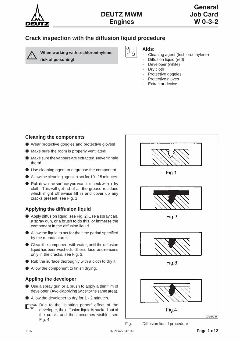
Crack inspection with the diffusion liquid procedure
Aids:- Cleaning agent (trichloroethylene)- Diffusion liquid (red)- Developer (white)- Dry cloth- Protective goggles- Protective gloves- Extractor device
Cleaning the components● Wear protective goggles and protective gloves!
● Make sure the room is properly ventilated!
● Make sure the vapours are extracted. Never inhalethem!
● Use cleaning agent to degrease the component.
● Allow the cleaning agent to act for 10 - 15 minutes.
● Rub down the surface you want to check with a drycloth. This will get rid of all the grease residueswhich might otherwise fill in and cover up anycracks present, see Fig. 1.
Applying the diffusion liquid● Apply diffusion liquid, see Fig. 2. Use a spray can,
a spray gun, or a brush to do this, or immerse thecomponent in the diffusion liquid.
● Allow the liquid to act for the time period specifiedby the manufacturer.
● Clean the component with water, until the diffusionliquid has been washed off the surface, and remainsonly in the cracks, see Fig. 3.
● Rub the surface thoroughly with a cloth to dry it.
● Allow the component to finish drying.
Appling the developer● Use a spray gun or a brush to apply a thin film of
developer. (Avoid applying twice to the same area).
● Allow the developer to dry for 1 - 2 minutes.
Due to the “blotting paper” effect of thedeveloper, the diffusion liquid is sucked out ofthe crack, and thus becomes visible, seeFig. 4.
Fig. Diffusion liquid procedure
25495 0
!When working with trichloroethylene:
risk of poisoning!

Page 2 of 2 0299 4272-0199 1197
GeneralJob Card DEUTZ MWMW 0-3-2 Engines
Assessment- It may happen that very thin cracks do not become
visible until several hours have passed.
- Due to the diffusion liquid being sucked upwards,red points will form in the white developer coatingwherever there are cracks or other surfaceirregularities.
- Red lines indicate cracks.
- Red dots indicate pitting and porosity.
- A dotted red line will appear in the case of:
- very fine cracks,
- metal fatigue,
- an only partial rupture.

0997 0299 3899-0122 Page 1 of 2
Cylinder headDEUTZ MWM Job Card
TBG 620/TBG 620K W 1-2-2
Valve lifter and valve lifter bracket: removing, checking and installing
Removing the valve lifter and the valvelifter bracket● Use the special pliers to withdraw the sparking
plug connector, and remove the cylinder headhood.
● Turn the engine so that the tappet of the valvemechanism at the cylinder unit concerned isdestressed, and the valves are closed, i.e. arepositioned at ignition TDC.
● Unscrew fixing nut 3 of the valve lifter bracket 2,and lift off the valve lifter bracket together with thevalve lifters 5 and 1.
New clearance Max. perm. clearance
Clearance betweenbearing journal andvalve lifter bore
0.050 … 0.091 0.130
Installing the valve lifter and the valvelifter bracket● Place the valve lifter bracket on the cylinder head,
positioning it by means of the centering bush andthe dowel pin.
● Screw on fixing nut and tighten .
● Adjust valve clearance,see Job Card B 1-1-1.
Tools:- Normal tools- Special pliers for sparking plug connector- Feeler gauge- Caliper gauge
Cross-references:- Job Card B 1-1-1- Operating Manual, Chapter 8, Tightening
instructions
Checking the valve lifter and the valvelifter bracketThe inspection routine for the removed parts coverschecking free passage of the lube oil ways in the valvelifter bracket and in the valve lifters themselves (cleanthem if necessary), checking proper fit of the screwplugs for these lube oil ways, checking for wear andtear at the contact areas of the clamping screws 4, andchecking the radial clearance between bearing journaland valve lifter bore (see table 1).
Replace parts if necessary.
[mm]
Table 1 Clearance
Comply with the tightening instructionsgiven in the Operating Manual,Chapter 8, „Technical Data“.

Page 2 of 2 0299 3899-0122 0997
Cylinder headJob Card DEUTZ MWMW 1-2-2 TBG 620/TBG 620K
50736 0
Fig. 1 Valve actuator, parts

0997 0299 3898-0122 Page 1 of 2
Cylinder headDEUTZ MWM Job Card
TBG 620/TBG 620K W 1-2-3
Valve actuator bridges, guide bolts: removing and installing
Check valve actuator bridges for zero-tilt mounting. Ifthere is perceptible play, replace valve actuator bridgesand/or guide bolts.
Removing the guide bolts for valveactuator bridges● Remove valve lifter and valve lifter bracket,
see Job Card W 1-2-2.
● Take off valve actuator bridges 2 with shims 3.Clean the parts.
● Check valve actuator bridges, shims and guidebolt 1 for wear and tear and traces of scoring.Replace any damaged parts.
● Bore the damaged guide bolt 1 inside to 8.5 mm.Cut an M10 thread, and withdraw guide bolt 1.
50737 0
Tools:- Normal tools- Extractor
Aids:- Nitrogen (liquid)
Cross-references:- Job Card W 0-3-1, B 1-1-1, W 1-2-2
Installing the guide bolts for valveactuator bridges● Supercool the bolt in liquid nitrogen (approx.
-190°C), and insert it without using any force.
● The top edge must lie 46-0.5 mm above the adjoiningcylinder head surface.
● Oil all the components of the valve mechanism.
● Fit valve actuator bridge onto the guide bolt with ashim.
● Install valve lifter and valve lifter bracket,see Job Card W 1-2-2.
● Adjust valve clearance,see Job Card B 1-1-1.
Fig. 1 Valve actuator
!Never touch liquid nitrogen andundercooled parts:
Risk of injury!
Page 2 of 2 0299 3898-0122 0997
Cylinder headJob Card DEUTZ MWMW 1-2-3 TBG 620/TBG 620K
This page intentionally left blank.
0997 0299 3897-0122 Page 1 of 2
Cylinder headDEUTZ MWM Job Card
TBG 620/TBG 620K W 1-3-1
Valve rotating device: removing, checking, and installing
Removing the valve rotating device● Remove valves,
see Job Card W 1-5-1.
● Take out valve rotating device.
Checking the valve rotating device● Clean the valve rotating device.
● Make a visual inspection to check for wear andtear.
● Check by hand that it moves freely.
If you find no defects after this check routine,you can continue to use the valve rotatingdevice. Otherwise replace the valve rotatingdevice.
Installing the valve rotating device● Insert the valve rotating device.
● Install valves,see Job Card W 1-5-1.
Tools:- Normal tools
Cross-references:- Job Card W 1-5-1

Page 2 of 2 0299 3897-0122 0997
Cylinder headJob Card DEUTZ MWMW 1-3-1 TBG 620/TBG 620K
This page intentionally left blank.
0997 0299 3894-0122 Page 1 of 2
Cylinder headDEUTZ MWM Job Card
TBG 620/TBG 620K W 1-4-0
Cylinder head nuts: hydraulically loosening and tightening
Tools:- Special tools- Hydraulic clamping device
Aids:- Lube oil
Cross-references:- Job Card W 0-0-1
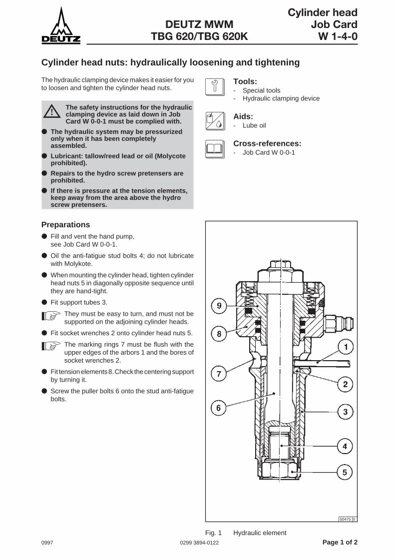
Preparations● Fill and vent the hand pump,
see Job Card W 0-0-1.
● Oil the anti-fatigue stud bolts 4; do not lubricatewith Molykote.
● When mounting the cylinder head, tighten cylinderhead nuts 5 in diagonally opposite sequence untilthey are hand-tight.
● Fit support tubes 3.
They must be easy to turn, and must not besupported on the adjoining cylinder heads.
● Fit socket wrenches 2 onto cylinder head nuts 5.
The marking rings 7 must be flush with theupper edges of the arbors 1 and the bores ofsocket wrenches 2.
● Fit tension elements 8. Check the centering supportby turning it.
● Screw the puller bolts 6 onto the stud anti-fatiguebolts.
The hydraulic clamping device makes it easier for youto loosen and tighten the cylinder head nuts.
!The safety instructions for the hydraulicclamping device as laid down in JobCard W 0-0-1 must be complied with.
● The hydraulic system may be pressurizedonly when it has been completelyassembled.
● Lubricant: tallow/reed lead or oil (Molycoteprohibited).
● Repairs to the hydro screw pretensers areprohibited.
● If there is pressure at the tension elements,keep away from the area above the hydroscrew pretensers.
50475 0
Fig. 1 Hydraulic element

Page 2 of 2 0299 3894-0122 0997
Cylinder headJob Card DEUTZ MWMW 1-4-0 TBG 620/TBG 620K
Tightening and loosening● Tighten the puller bolts hand-tight.
- When tightening the nuts, turn the puller boltsback by 90°.
- When loosening the nuts, turn the puller boltsback by 180°.
By tightening and then turning back the pullerbolts, you will prevent the puller bolts and thecylinder head nuts locking each other whenthe pressure is bled off in the clamping device.
● Connect clamping devices 1 to hand pump 2 viahigh-pressure hoses, see Fig. 2.
- Do NOT operate the hand pump beforethe high-pressure hoses have beenproperly secured!
- Never place yourself in the direction ofpull behind or above the hydraulicpreclamping device, for as long as it isunder pressure!
● Bring piston 9 of the tension elements into itsstarting position, see Fig. 1.
● Open vent screw 3 by one turn, see Fig. 2.
● Close drain plug 4, see Fig. 2.
● Operate pump lever 1, until 150....160 bar havebeen reached, see Fig. 2.
● Use arbor 1 to tighten all socket wrench andcylinder head nuts hand-tight, see Fig. 1.
● Slowly open drain plug 4, reduce pressure down to0 bar, see Fig. 2.
● Close the drain plug.
● Operate pump lever until 720....730 bar have beenreached.
● Use the arbor to tighten all socket wrench andcylinder head nuts hand-tight, see Fig. 1.
This hand-tight tightening procedure means3...3,5 holes which can be turned further. Ifthis is not the case, find and eliminate thecause (e.g. thread damaged, soiled with paint,erection error, device defective, etc.).
● Slowly open the drain plug, reduce pressure to0 bar.
● Remove clamping devices.
50477 0
50476 1
!
Fig. 2 Hand pump
Fig. 3 Hydraulic clamping device

0997 0299 3891-0122 Page 1 of 2
Cylinder headDEUTZ MWM Job Card
TBG 620/TBG 620K W 1-4-2
Cylinder head: checking
The inspection intervals for cylinder heads can varywidely, depending on the engine’s operating conditionsand loading, and on the quality of the fuel and the lubeoil quality.
Tools:- Normal tools- Endoscope
Cross-references:- Job Card W 0-3-2, W 1-3-1, W 1-4-1,
W 1-5-1, W 1-6-1, W 1-7-1, W 1-7-2
Checking the cylinder head● Make your inspection in conjunction with an
endoscope,see Job Card W 1-7-2.
If you don’t have an endoscope available, youwill have to remove a cylinder head. (Don’tchoose one from the end of a cylinder row).
● Inspect the cylinder head with the worst-lookingcombustion compartment, following the proceduredescribed below.
● Remove the cylinder head,see Job Card W 1-4-1.
● Check the combustion-compartment side of thecylinder head for cracks,see Job Card W 0-3-2.
● Check the screw plug for leaks.
● Flush the coolant compartment with cold cleaningagent; if there are significant scale deposits, usescale-dissolving agents to remove them (followthe manufacturer’s instructions).
● Remove valves,see Job Card W 1-5-1.
● Check valve lifter mounting for wear and tear.
● Check valve rotating device,see Job Card W 1-3-1.
● Check valve guide,see Job Card W 1-6-1.
● Check valves and valve seat rings,see Job Card 1-7-1.
- If previous inspections have proved positive, theinspection routine for the other cylinder heads canbe postponed for another combustion-compartmentcheck interval. When this interval has elapsed,check the combustion compartments once moreas detailed above.
- If everything is again in order, then you can postponeinspection of all cylinder heads once more foranother combustion compartment inspectioninterval.
- If, however, you find excessive wear and tear at thecylinder head which you check, then you mustcheck all the other cylinder heads as well, andrepair them as necessary.
- The number of operating hours run by the engineup to the date when all cylinder heads have to bechecked for the first time is defined as the inspectioninterval for the cylinder heads.
● Install valves,see Job Card W 1-5-1.
● Fit cylinder head,see Job Card W 1-4-1.

Page 2 of 2 0299 3891-0122 0997
Cylinder headJob Card DEUTZ MWMW 1-4-2 TBG 620/TBG 620K
This page intentionally left blank.

0997 0299 3895-0122 Page 1 of 4
Cylinder headDEUTZ MWM Job Card
TBG 620/TBG 620K W 1-4-4
Cylinder head: removing and fitting
Add-on pieces fitted to the engine will vary, dependingon he options the client chooses, and the particularapplication concerned. This will, for example, apply tothe exhaust gas system, the turbocharger equipment,and the electrics. These features may entail additionalwork. The procedures involved are not describedhere.
Removing the cylinder head● Drain off the coolant,
see Job Card W 9-0-1.
● Remove all requisite covers.
● Take off air intake pipe. coolant drain pipe, exhaustgas collecting pipe, oil pressure line (if any), and oilreturn line, and use special pliers to withdraw thesparking plug connector.
● Remove combustion-compartment temperatureprobe from cylinder head.
● Remove valve lifter and valve lifter bracket,see Job Card W 1-2-2.
● Take off valve lifter actuator bridges.
● Remove fixing nuts for cylinder head. When usinga hydraulic clamping device,see Job Card, W 1-4-0.
● Screw mounting device for lifting off the cylinderhead onto the bolt of the valve lifter bracketmounting.
● Use the mounting device to carefully lift off thecylinder head.
Take special care to ensure that the stud boltsdo not get damaged.
● Once you have removed the cylinder head, placeit on a wooden board.
The safety instructions for work on thedrive mechanism must be complied withas detailed in Job Card W 2-0-1.
!
Tools:- Normal tools- Mounting device for lifting off the cylinder
head- Rail for aligning the cylinder heads
Aids:- Lube grease
Cross-references:- Job Card W 1-2-2, W 1-4-0, W 2-0-1,
W 9-0-1, W 1-4-2
Page 2 of 4 0299 3895-0122 0997
Cylinder headJob Card DEUTZ MWMW 1-4-4 TBG 620/TBG 620K
Fitting the cylinder head● Clean the cylinder head completely. Remove any
remains of seals.
● Check cylinder head for damage,see Job Card W 1-4-2.
● Check threads of the four stud bolts along theirentire length for faultless condition and easy nutmovement.
● Check nuts and washers, replace if necessary.
● Clean the sealing surface on the cylinder liner.
● Clean the contact areas and seat surfaces forsealing rings and round sealing rings on the cylinder.
● Grease all the round sealing rings before fittingthem.
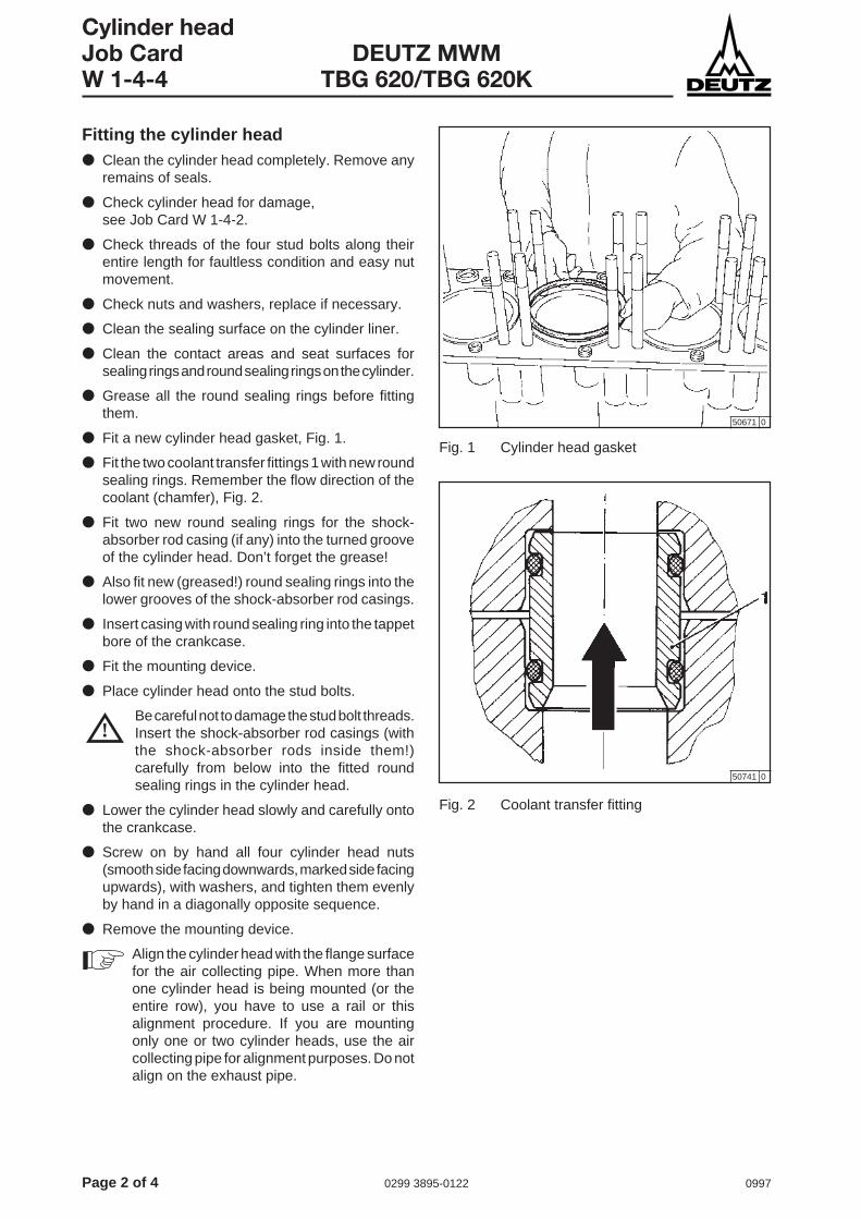
● Fit a new cylinder head gasket, Fig. 1.
● Fit the two coolant transfer fittings 1 with new roundsealing rings. Remember the flow direction of thecoolant (chamfer), Fig. 2.
● Fit two new round sealing rings for the shock-absorber rod casing (if any) into the turned grooveof the cylinder head. Don’t forget the grease!
● Also fit new (greased!) round sealing rings into thelower grooves of the shock-absorber rod casings.
● Insert casing with round sealing ring into the tappetbore of the crankcase.
● Fit the mounting device.
● Place cylinder head onto the stud bolts.
Be careful not to damage the stud bolt threads.Insert the shock-absorber rod casings (withthe shock-absorber rods inside them!)carefully from below into the fitted roundsealing rings in the cylinder head.
● Lower the cylinder head slowly and carefully ontothe crankcase.
● Screw on by hand all four cylinder head nuts(smooth side facing downwards, marked side facingupwards), with washers, and tighten them evenlyby hand in a diagonally opposite sequence.
● Remove the mounting device.
Align the cylinder head with the flange surfacefor the air collecting pipe. When more thanone cylinder head is being mounted (or theentire row), you have to use a rail or thisalignment procedure. If you are mountingonly one or two cylinder heads, use the aircollecting pipe for alignment purposes. Do notalign on the exhaust pipe.
50671 0
50741 0
!
Fig. 1 Cylinder head gasket
Fig. 2 Coolant transfer fitting
0997 0299 3895-0122 Page 3 of 4
Cylinder headDEUTZ MWM Job Card
TBG 620/TBG 620K W 1-4-4
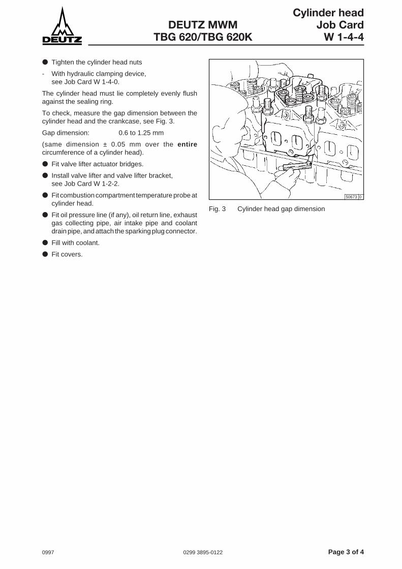
● Tighten the cylinder head nuts
- With hydraulic clamping device,see Job Card W 1-4-0.
The cylinder head must lie completely evenly flushagainst the sealing ring.
To check, measure the gap dimension between thecylinder head and the crankcase, see Fig. 3.
Gap dimension: 0.6 to 1.25 mm
(same dimension ± 0.05 mm over the entirecircumference of a cylinder head).
● Fit valve lifter actuator bridges.
● Install valve lifter and valve lifter bracket,see Job Card W 1-2-2.
● Fit combustion compartment temperature probe atcylinder head.
● Fit oil pressure line (if any), oil return line, exhaustgas collecting pipe, air intake pipe and coolantdrain pipe, and attach the sparking plug connector.
● Fill with coolant.
● Fit covers.
50673 0
Fig. 3 Cylinder head gap dimension

Page 4 of 4 0299 3895-0122 0997
Cylinder headJob Card DEUTZ MWMW 1-4-4 TBG 620/TBG 620K
This page intentionally left blank.

0997 0299 3896-0122 Page 1 of 2
Cylinder headDEUTZ MWM Job Card
TBG 620/TBG 620K W 1-5-1
Valves: removing and installing
50667 0
When working on the valve mechanism, you musttake special care to keep everything absolutely clean.Never use magnetic tools.
Tools:- Normal tools- Removal and installation lever for valve
springs
Aids:- Wooden board- Lube oil
Cross-references:- Job Card W 1-2-2, W 1-4-4, W 1-7-1
● Fit shim on valve.
● Press down the valve spring.
● Remove the valve clamping cone.
● Destress the valve spring.
● Take out the valve spring disk, the valve spring andthe valve rotating device.
● Lay the cylinder head lengthways.
● Pull the inlet and exhaust valves out of the valveguides
● Check valves and valve seat rings,see Job Card W 1-7-1.
! Accident risk!
Springs are under tension.
Removing valves● Remove cylinder head,
see Job Card W 1-4-4.
● Place cylinder head with combustion-compartmentside on something soft (e.g. wood).
● Remove valve lifters and valve lifter brackets,see Job Card W 1-2-2.
● Take off valve actuator bridges.
● Screw the removal lever for valve springs onto thebolt for the valve lifter bracket mounting.
Fig. 1 Removal and installation lever
Page 2 of 2 0299 3896-0122 0997
Cylinder headJob Card DEUTZ MWMW 1-5-1 TBG 620/TBG 620K
Installing the valves● Replace the valve springs, clamping cones and
valve spring disks.
● Oil the valve stem and valve guide.
● Insert valves 1 carefully, making sure that theround sealing ring in the valve guide does not getdamaged.
● Fit valve rotating device, valve spring and valvespring disk 3.
● Place supports underneath the cylinder head sothat the valve disks are flush.
● Fit shim 5 onto valve spring disk 3.
● Press down the valve spring 4.
● Insert the valve clamping cone 2.
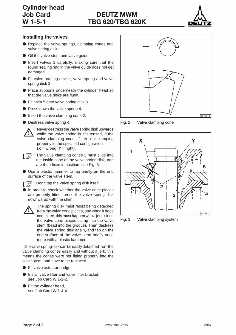
● Destress valve spring 4.
Never destress the valve spring disk upwardswhile the valve spring is still tensed, if thevalve clamping cones 2 are not clampingproperly in the specified configuration(X = wrong, Y = right).
The valve clamping cones 2 must slide intothe inside cone of the valve spring disk, andare then fixed in position, see Fig. 3.
● Use a plastic hammer to tap briefly on the endsurface of the valve stem.
Don’t tap the valve spring disk itself.
● In order to check whether the valve cone piecesare properly fitted, press the valve spring diskdownwards with the shim.
The spring disk must resist being detachedfrom the valve cone pieces, and when it doescome free, this must happen with a jerk, sincethe valve cone pieces clamp into the valvestem (bead into the groove). Then destressthe valve spring disk again, and tap on theend surface of the valve stem briefly oncemore with a plastic hammer.
If the valve spring disk can be easily detached from thevalve clamping cones easily and without a jerk, thismeans the cones were not fitting properly into thevalve stem, and have to be replaced.
● Fit valve actuator bridge.
● Install valve lifter and valve lifter bracket,see Job Card W 1-2-2.
● Fit the cylinder head,see Job Card W 1-4-4.
50738 0
50739 1
!
!
Fig. 2 Valve clamping cone
Fig. 3 Valve clamping system

0997 0299 3884-0122 Page 1 of 2
Cylinder headDEUTZ MWM Job Card
TBG 620/TBG 620K W 1-6-1
Valve guides: checking, removing and installing
When a cylinder head is being repaired, the valveguides must be checked for wear and tear.
If the inside diameter of the valve guides is greaterthan 11.11 mm, they must be replaced. Likewise ifthere is excessive scoring.
Removing the valve guides● Removing the valves,
see Job Card W 1-5-1.
● Use a press and a press-out mandrel to press outthe valve guides.
After pressing out the guide, check the locationhole in the cylinder head. If the hole is largerthan 18.018 mm or is damaged, the cylinderhead must be reworked in a DEUTZ MWMService to ensure the correct overdimension.(At a hole diameter of > 19.018 mm, thecylinder head must be replaced.)
Installing the valve guides● Supercool the valve guides in liquid nitrogen
(approx. -190 °C). Insert them dry (i.e. without oil),using no force, into the location hole of the cylinderhead, with the end stepped by 1 mm in diametergoing first. Use a press-in mandrel for guidance.Make sure the protruding dimensionC = 23.0 ± 0.200 mm above the contact area of thevalve rotating device is correct.
● Working with liquid nitrogen,see Job Card W 0-3-1.
● To check, test whether a long mandrel movesfreely in the valve guide.
● If it does not move freely, you must rework with asingle-stroke honing tool. NEVER ream it!
● Wet new round sealing ring 2 with engine oil, andinsert in valve guide 1.
● Install valves,see Job Card W 1-5-1.
50740 1
Tools:- Normal tools- Digital caliper gauge- Press-out mandrel- Press-in mandrel- Single-stroke honing tool- Inside calipers
Aids:- Engine oil- Nitrogen (liquid)
Cross-references:- Job Card W 1-5-1, W 0-3-1
Fig. 1 Valve guide

Page 2 of 2 0299 3884-0122 0997
Cylinder headJob Card DEUTZ MWMW 1-6-1 TBG 620/TBG 620K
This page intentionally left blank.

0997 0299 3887-0122 Page 1 of 2
Cylinder headDEUTZ MWM Job Card
TBG 620/TBG 620K W 1-7-1
Valves and valve seat rings: checking
Defective engine condition, poor fuel and coolingwater conditioning, and inadequate preheating,impermissible torque operation (speed drop withongoing engine block), etc., may cause prematurefailure of valves.
Tools:- Normal tools- Digital caliper gauge- Magnifying glass (at least 4-fold magni-
fication)
Aids:- Distillate fuel
Cross-references:- Job Card W 1-5-1
Checking the valves and valve seatrings● Remove the valves,
see Job Card W 1-5-1.
● Clean the seat surface to remove any residues.
● Use a scraper to remove any coking on the valvedisks and seat rings, and wash down with distillatefuel.
To make it easier to remove water-soluble residueswith a sulphur content, the run valve cones can beplaced in water for a few hours.
Checking the valve seat ringsThe valve seat rings can continue to be used, providedthe following preconditions are met:
- seat surface without burn-outs, blow-throughs,cracks or impact traces.
If the valve seat rings exhibit coke impacts, scoring,stepping or corrosion, etc., the seat surfaces of thevalve seat rings must be repaired in their installedstate.
● Install valves,see Job Card W 1-5-1.
Reworking of the valve seat rings may becarried out only by an authorized workshop.
Checking the valvesThe valve cones can continue to be used, providedthe following preconditions are met:
- seat surface without any burn-outs, blow-throughs,cracks, or impact traces,
- no damage to the chrome layer,
- no corrosion scars,
- stem diameter min. 10.93 mm,
- no damage to the clamp cone groove.
The seat surface of the valve cone must be repairedif:
- the cleaned seat surface is not free of coke impacts,blow-throughs, pittings and other damage (checkwith a magnifying glass).

Page 2 of 2 0299 3887-0122 0997
Cylinder headJob Card DEUTZ MWMW 1-7-1 TBG 620/TBG 620K
This page intentionally left blank.

0997 0299 3900-0122 Page 1 of 2
Cylinder headDEUTZ MWM Job Card
TBG 620/TBG 620K W 1-7-3
Valve seat ring: removing and installing
Tools:- Normal tools- Electric welding unit- Inside calipers- Digital caliper gauge- Press
Aids:- Nitrogen (liquid)
Cross-references:- Job Card W 1-5-1, W 1-7-1, W 0-3-1
If the damage involved cannot be eliminated within thepermissible reworking limits, or if the maximumpermissible residual dimension between bottom edgeof valve and the bottom of the cylinder head cannot becomplied with, even when new valves are fitted, thenthe valve seat rings must be replaced.
Removing the valve seat rings● Remove the valves,
see Job Card W 1-5-1.
● Check valves and valve seat rings,see Job Card W 1-7-1.
● Place a Ø 2 mm electric welding electrode at 130 Aaround the valve seat ring. The deformation willcause the valve seat ring to drop out.
Do not set a higher current, otherwise youmay damage the cylinder head.
Check reference dimensions for valve seat ring.- Location hole in the cylinder head, table 1.
Installing new valve seat rings:● Supercool inlet and exhaust valve seat rings in
liquid nitrogen (approx. -190°C) and insert themwithout applying any force. Use a press to press inthe valve seat rings, using a force of 12000 N(approx. 1200 kp), and maintaining this pressureforce for not less than 15 seconds.
● Newly fitted valve seat rings must be ground intogether with the associated valves.
● Install valves,see Job Card W 1-5-1.
-0 -0
[mm] Inlet Exhaust
Valve seat ring Ø 60 +0.019 Ø 58 +0.019
Hole depth 15 +0.02 15 +0.02+0.05
Table 1 Dimensions
+0.05
Page 2 of 2 0299 3900-0122 0997
Cylinder headJob Card DEUTZ MWMW 1-7-3 TBG 620/TBG 620K
This page intentionally left blank.

0997 0299 3901-0122 Page 1 of 2
Cylinder headDEUTZ MWM Job Card
TBG 620/TBG 620K W 1-10-2
Removing and installing the sparking plug guard sheath
Tools:- Normal tools- Special nut for removing the bottom guard
sheath
Aids:- Screw-locking compound
Cross-references:- Job Card W 1-2-2- Operating instructions, Chapter 8,
tightening instructions
Removing the guard sheath● Remove valve lifter and valve lifter bracket,
see Job Card W 1-2-2.
● Take off valve actuator bridges.
● Remove sparking plug.
● Unscrew top guard sheath 1.
● Remove bottom guard sheath.
Installing the guard sheath● Clean the bottom guard sheath, fit new seals,
apply screw-locking compound, insert sheath inthe cylinder head, and tighten.
● Screw the top guard sheath into the cylinder head,with screw-locking compound, and tighten.
● Install sparking plug.
● Fit valve actuator bridges.
● Install valve lifter and valve lifter bracket,see Job Card W 1-2-2.
81066 0
Fig. 1 Sparking plug guard sheath
Comply with the tightening instructionsgiven in the Operating Manual,Chapter 8, „Technical Data“.

Page 2 of 2 0299 3901-0122 0997
Cylinder headJob Card DEUTZ MWMW 1-10-2 TBG 620/TBG 620K
This page intentionally left blank.
1097 0299 6317-0199 Page 1 of 2
Drive mechanismDEUTZ MWM Job Card
Engines W 2-0-1
Safety rules for working on the drive mechanism
Before starting work● Shut down the engine, and secure it against being
started up again.
● If necessary, drain off lube oil and/or coolant, andcollect it for re-use. Caution: risk of scalding!
● With diesel engines, open the indexing cocks. Withgas engines, remove the spark plugs.
● If it is fitted on your engine, open the inspectionhole cover 10 minutes at the earliest AFTER theengine has been shut down, and after oil circulationhas been interrupted.
● Do not perform any other work on the drivemechanism until the engine has cooled downsufficiently. The engine must have cooled downenough to ensure that there is no longer any risk ofburns.
● When working on the exhaust gas system,remember that in spite of long cooldown ties somecomponents may still be hot. Heat guard platescan have sharp edges, so wear protective gloves.
● Do not start the work until a sufficient ventilationperiod has elapsed.
● Make sure that the environment is clean in whichthe engine is going to be opened up.
!When you are performing any work on thedrive mechanism, you MUST alwayscomply with the following rules.
During the work● Make sure that no dirt can penetrate into the drive
compartment.
● Before turning the crankshaft, check that:
- the turning device has engaged properly,
- there are no persons working in or at the engine,
- no tools are impeding the crankshaft from turningand might thus cause damage,
- the drive mechanism is not being put out ofequilibrium by the removal o drive mechanismparts.
● Make sure that the engine cannot turnunintentionally.
After finishing work● Before you close the engine, check whether you
have removed all tools, cleaning cloths, etc. fromthe crank compartment.
● Fit inspection hole cover (if any), with new seals.
● Before starting up, turn the engine with openindexing cocks or (in the case of gas engines) withspark plugs not installed.
● With diesel engines, close indexing cocks. Withgas engines, install spark plugs.
● Fill with lube oil. Top up coolant, vent coolingsystem, and check for leaks.
!! Danger of burst!
Page 2 of 2 0299 6317-0199 1097
Drive mechanismJob Card DEUTZ MWMW 2-0-1 Engines
This page has been intentionally left blank.

0997 0299 3886-0122 Page 1 of 2
Drive mechanismDEUTZ MWM Job Card
TBG 620/TBG 620K W 2-1-0
Drive mechanism: checking
The safety instructions for work on thedrive mechanism must be complied withas detailed in Job Card W 2-0-1.
!Tools:- Normal tools- Turning device
Cross-references:- Job Card W 2-0-1, W 2-15-1
When you are doing this work, take care toensure that the spray jets of the pistoncooling systems do not get bent,see Job Card W 2-15-1.
● Feel the bearing covers at the crankshaft andconnecting rods, to check whether they areexhibiting a uniform temperature.
● Check the drive mechanism for soiling. Pay specialattention to checking for bearing metal in the oilpan, and for corrosion and water leaks.
● Make a careful check of the cylinder liner contactsurface an the liner seals on the drive compartmentside. Note that when you do this the pistons mustbe at TDC.
● Carry out a lubrication check:
- Operate and check the prelubrication pump,to see whether lube oil exits visibly at everybearing.
- Take off the cylinder head hood. Carry out acorresponding check at the valve lifter bearings.

Page 2 of 2 0299 3886-0122 0997
Drive mechanismJob Card DEUTZ MWMW 2-1-0 TBG 620/TBG 620K
This page intentionally left blank.

0997 0299 3885-0122 Page 1 of 2
Drive mechanismDEUTZ MWM Job Card
TBG 620/TBG 620K W 2-1-1
a
D
Checking the bearing spread
The bearing shell must exhibit a positive spread, sothat it is properly flush against the acceptance borewhen it has been installed.
All new bearing shells exhibit a positive spread, unlessthey have been incorrectly handled (e.g. in transit).
Tools:- Slide gauge
80227 0
1. DefinitionPositive spread:
Measured at room temperatures, Dimension „a“ isgreater than Dimension „D“.
Negative spread:
Dimension „a“ smaller than Dimension „D“.
Crankshaft bearing: Dimension „D“ etched intothe end fact of the bearing shell,
Connecting-rod bearing: must be measured directlyat the bearing cover.
2. AssessmentIf a used bearing shows negative spread, this may (ifno other reasons can be detected) be an indicationthat the bearing has undergone plastic deformationdue to overheating and has thus lost its initial tension.
Bearing shells with a negative spread must nolonger be used.
Do not attempt to correct with any tool, since there isa risk that the bearing metal will become detachedfrom the support shell, or that the bearing will bedeformed. This sort of damage can lead to seriousoperational malfunctions.
3. Setpoint values[mm] Conn. rod b.
Spread „a“ 135.025 + 0.4
Fig. 1 Spread

Page 2 of 2 0299 3885-0122 0997
Drive mechanismJob Card DEUTZ MWMW 2-1-1 TBG 620/TBG 620K
This page intentionally left blank.

0997 0299 6321-0199 Page 1 of 10
Drive mechanismDEUTZ MWM Job CardGas engines W 2-1-6
Visual inspection of the bearing shells
Please take the precise point in time when to inspectthe connecting-rod and crankshaft bearings from theoperating instructions, “Maintenance and Servicing”.
Tools:- Magnifying glass, 5-fold magnification
Cross-references:- Job Cards W 2-1-1, W 2-7-2,
W 2-9-1, W 2-9-3- Operating instructions
How to proceed:You must check the bearing shells by means of avisual inspection and by checking the bearing shellspread.
Under a basic overhaul routine (for precise intervalssee operating instructions “Maintenance andservicing”), connecting-rod and crankshaft bearingsmust always be replaced.
Removing the bearing shells● Remove piston with connecting rod,
see Job Card W 2-9-1 and/or W 2-9-3.
● Remove main bearing,see Job Card W 2-7-2.
● Check bearing spread,see Job Card W 2-1-1
Visual inspection of the slide bearings
Running pattern of the bearing shellsMaterial: steel/aluminium alloy
Depending on the number of operating hours and onthe operating conditions involved, used bearing shellswill exhibit different running patterns. The essentialdifferences can often be recognized only by a properlytrained and specialized expert. If in doubt, werecommend you to consult DEUTZ service for theassessment of the bearing shells concerned.
If the inspection reveals a poor running pattern on theconnecting-rod bearings and/or deep dirt scoring or alot of embedded dirt, then you must additionally checka crankshaft bearing.
Page 2 of 10 0299 6321-0199 0997
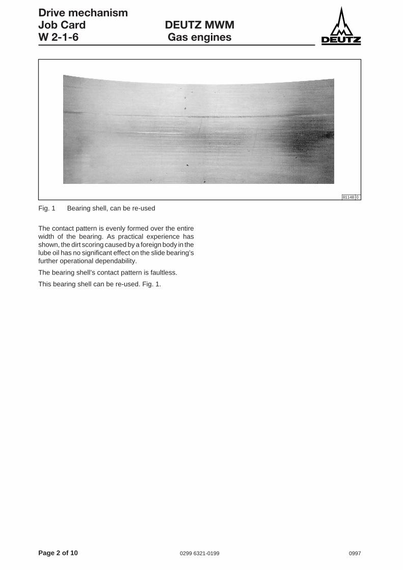
Drive mechanismJob Card DEUTZ MWMW 2-1-6 Gas engines
The contact pattern is evenly formed over the entirewidth of the bearing. As practical experience hasshown, the dirt scoring caused by a foreign body in thelube oil has no significant effect on the slide bearing’sfurther operational dependability.
The bearing shell’s contact pattern is faultless.
This bearing shell can be re-used. Fig. 1.
81148 0
Fig. 1 Bearing shell, can be re-used

0997 0299 6321-0199 Page 3 of 10
Drive mechanismDEUTZ MWM Job CardGas engines W 2-1-6
81149 0
Fig. 2 Bearing shell, can be re-used
The contact pattern is evenly formed over the entirewidth of the bearing.
The bearing shell’s contact pattern is impeccable.
This bearing shell can be re-used. Figs. 2 and 3.
81191 0
Fig. 3 Detail for Fig. 2
Page 4 of 10 0299 6321-0199 0997
Drive mechanismJob Card DEUTZ MWMW 2-1-6 Gas engines
81150 0
Fig. 4 Bearing shell, can be re-used if appropriate
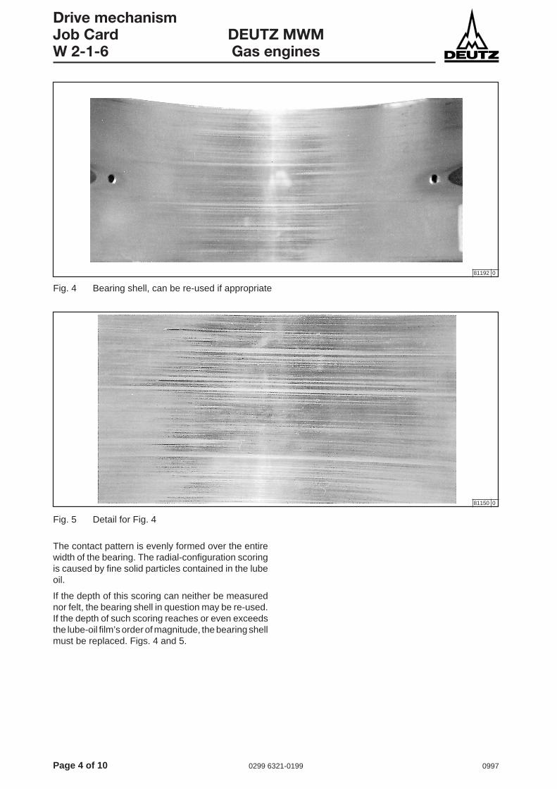
The contact pattern is evenly formed over the entirewidth of the bearing. The radial-configuration scoringis caused by fine solid particles contained in the lubeoil.
If the depth of this scoring can neither be measurednor felt, the bearing shell in question may be re-used.If the depth of such scoring reaches or even exceedsthe lube-oil film’s order of magnitude, the bearing shellmust be replaced. Figs. 4 and 5.
81192 0
Fig. 5 Detail for Fig. 4

0997 0299 6321-0199 Page 5 of 10
Drive mechanismDEUTZ MWM Job CardGas engines W 2-1-6
81151 0
Fig. 6 Bearing shell, cannot be re-used
The contact pattern shows a marked edge carrier withtraces of scoring in the slide layer made of aluminiumalloy.
You must find out what caused this slide-bearingdamage, and eliminate the cause. Fig. 6.
This bearing shell cannot be re-used.

Page 6 of 10 0299 6321-0199 0997
Drive mechanismJob Card DEUTZ MWMW 2-1-6 Gas engines
Fig. 7 Bearing shell, cannot be re-used
Fig. 8 Bearing shell, cannot be re-used
81153 0
81152 0
The contact pattern exhibits large-area damage withvarying degrees of scoring.
You must find out what caused this slide-bearingdamage, and eliminate the cause. Fig. 7.
This bearing shell cannot be re-used.
The loaded area of the bearing shell exhibits broken-off bearing metal pieces. Some broken-off pieces arelying around loose in the fatigue zone.
These have been caused by fatigue in the slide layerof the aluminium alloy. The surface structure at thebottom of the break-out indicates good bondingbetween steel and aluminium alloy.
This bearing shell cannot be re-used. Fig. 8.

0997 0299 6321-0199 Page 7 of 10
Drive mechanismDEUTZ MWM Job CardGas engines W 2-1-6
Fig. 9 Bearing shell, cannot be re-used
81154 0
This bearing shell exhibits broken-off bearing metalpieces.
These have been caused by fatigue in the slide layerof the aluminium alloy. The surface structure at thebottom of the break-out indicates good bondingbetween steel and aluminium alloy.
This bearing shell cannot be re-used. Fig. 9.

Page 8 of 10 0299 6321-0199 0997
Drive mechanismJob Card DEUTZ MWMW 2-1-6 Gas engines
3
2
1
4
= 580231 1
Visual inspection of the deep-groovebearings
Running pattern of the bearing shellsMaterial: steel/aluminium alloy
In its as-new condition, the contact surface exhibitsapprox. 75 % electroplated contact layer and approx.25 % of light metal.
● Use a magnifying glass to assess the wear-and-tear status of the contact surface (magnification atleast 5-fold). Contact surface is visible as the darkzone and the light-metal rib as the light-colouredzone.
● Crucial for wear-and-tear status:- Ratio of width of light-metal rib and width ofgroove, plus- extent of the worn surface.
● Each time you are assessing groove states, youmust adduce the contact surface in the less loadedarea (in most cases groove status as new) as acomparison.
A distinction must be made between the followingcases:
Case 1 (Fig. 10):
Definition of the contact-surface areas
1 Max. 30 % of the shell’s circumference
2 Max. 70 % of the width
3 Max. 50 % of the shell’s circumference
4 Max. 35 % of the width
5 Wear-and-tear 1 : 1
Fig. 10 Bearing shell (deep-groove bearing) Case 1, can be re-used if appropriate
Assessment
In places, the bearing is worn to such an extent thatthe bearing metal ribs and the grooves in the contactlayer have reached a ratio of 1 : 1. The width of thebearing metal ribs has increased from 25 % (as-newcondition) to 50 %. There is still some contact layer leftin the grooves.
If a wear-and-tear status as described in Case2 below must be anticipated within the nextinspection interval, then the bearing must bereplaced.
0997 0299 6321-0199 Page 9 of 10
Drive mechanismDEUTZ MWM Job CardGas engines W 2-1-6
4
3
2
5
= 7
61
= 880232 1
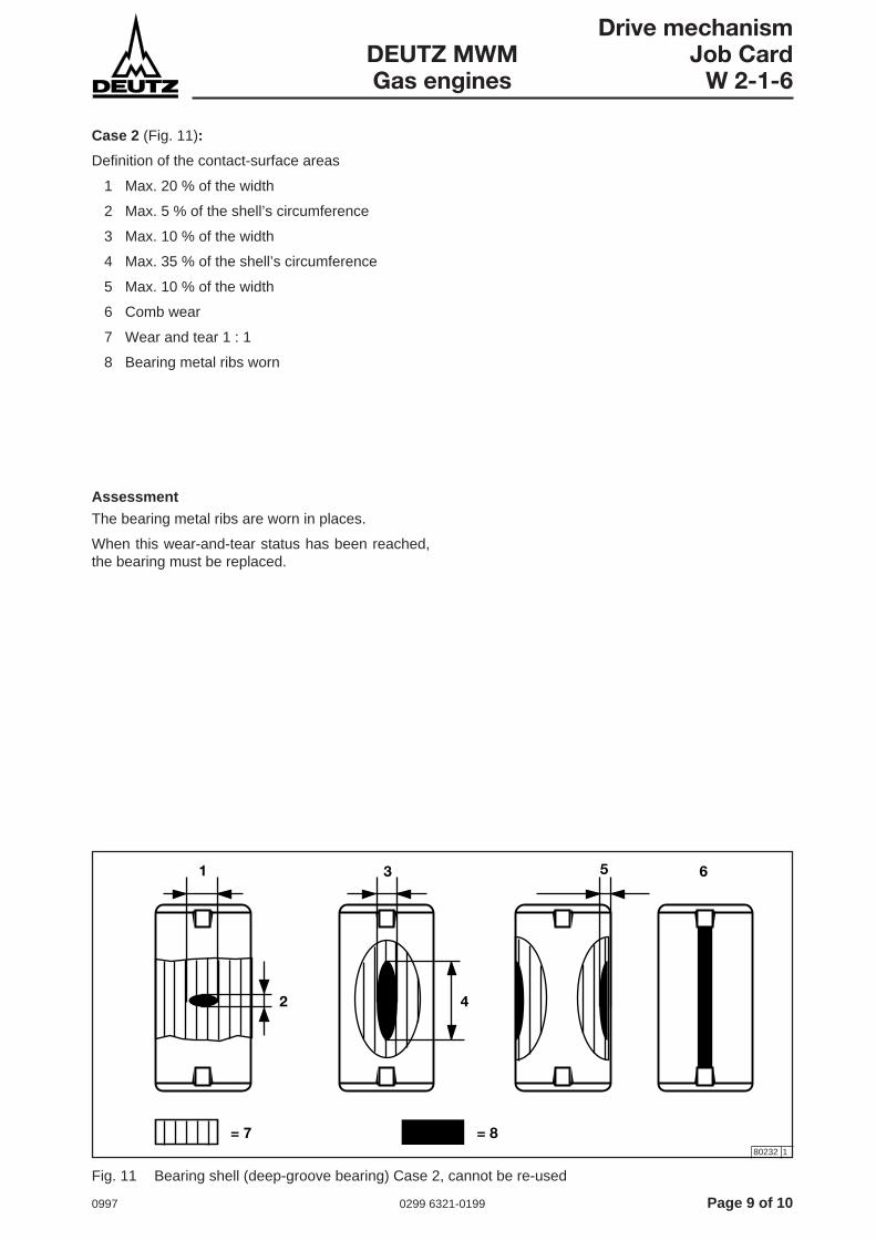
Case 2 (Fig. 11):
Definition of the contact-surface areas
1 Max. 20 % of the width
2 Max. 5 % of the shell’s circumference
3 Max. 10 % of the width
4 Max. 35 % of the shell’s circumference
5 Max. 10 % of the width
6 Comb wear
7 Wear and tear 1 : 1
8 Bearing metal ribs worn
Fig. 11 Bearing shell (deep-groove bearing) Case 2, cannot be re-used
Assessment
The bearing metal ribs are worn in places.
When this wear-and-tear status has been reached,the bearing must be replaced.

Page 10 of 10 0299 6321-0199 0997
Drive mechanismJob Card DEUTZ MWMW 2-1-6 Gas engines
This page intentionally left blank.

0997 0299 3930-0122 Page 1 of 2
Drive mechanismDEUTZ MWM Job Card
TBG 620/TBG 620K W 2-2-1
Removing and installing the bearing race (drive end)
50756 1
Tools:- Normal tools- Sealant Hylomar
Cross-references:- Job Card W 2-0-1, W 2-2-2, W 12-6-1- Operating Instructions, Chapter 8,
Tightening Instructions
After a lengthy period of running, a lead-in groove onthe bearing race 2 will form underneath the sealing lipof the shaft sealing ring 1. Provided the shaft sealingring is not replaced, this will in most cases not impairthe sealing effect.
Install a new shaft sealing ring, see Job CardW 2-2-2, in the end wall cover, axially offset by approx.3 mm, so that it effectively seals next to the old lead-in groove. In the case of the end wall cover at thecoupling-end, this is possible only if the distancebetween the old groove and the free end of the bearingrace is not less than 7.5 mm. Otherwise (and if theshaft sealing ring has already been repositioned once)you will have to replace the bearing race.
Removing and fitting the flywheel see Job Card W 12-6-1.
Installing the bearing race● Apply sealant.
● Press the new bearing race on, with the largerdiameter at the front (the inner diameter of thebearing races is slightly conical).
● Press the ring on, evenly and without tilting it (usea “soft” interlayer). The shoulder of the flywheelflange must be evenly flush all the way round.
Fig. 1, X: flush with the worked outer surface
After pressing on:
● Check that the lead-in bevel for the shaft sealingring is in faultless condition.
● Fit the flywheel flange, and tighten the anti-fatiguebolts 4 as specified in the Operating Instructions,Chapter 8, Tightening Instructions.
The safety instructions for work on thedrive mechanism must be complied withas detailed in Job Card W 2-0-1.
!
Removing the bearing race● Remove flywheel flange 3.
● Apply a thin welding bead or individual weldingspots at regular intervals on the bearing race.
● Take off bearing race.
If necessary, cut through the bearing racewith a flat chisel, in the longitudinal direction ofthe crankshaft. Take care not to damage thecrankshaft.
● Remove the residues of the old sealant, to ensurean absolutely clean surface.
Fig. 1 Bearing race
Comply with the tightening instructionsgiven in the Operating Manual,Chapter 8, „Technical Data“.

Page 2 of 2 0299 3930-0122 0997
Drive mechanismJob Card DEUTZ MWMW 2-2-1 TBG 620/TBG 620K
This page intentionally left blank.

0997 0299 3929-0122 Page 1 of 2
Drive mechanismDEUTZ MWM Job Card
TBG 620/TBG 620K W 2-2-2
50756 1
Removing and installing the crankshaft sealing ring (drive end)
Tools:- Normal tools- Sealant Loctite 574
Cross-references:- Job Card W 2-0-1, W 2-2-1, W 12-6-1
Different shaft sealing rings are fitted at theflywheel and vibration-absorber ends, andyou must be careful not to mix them up. Theones at the free end (= vibration-absorberend) have a right-hand twist, and the those atthe drive end (= vibration-absorber end) havea left-hand twist.
Removing and fitting the flywheelsee Job Card W 12-6-1.
Take note of the markingsThere is a directional arrow and letters reading“Schwungradseite“ (flywheel end) and “Schwing-ungsdämpferseite“ (vibration-absorber end) outsideon the dust lip.
The safety instructions for work on thedrive mechanism must be complied withas detailed in Job Card W 2-0-1.
!
Removing the crankshaft sealing ringRaplce shaft sealing ring 1 only if there is aleak or (after dismantling operations) if thereis visible wear and tear at the sealing lip (widthgreater than 1 mm).
● Check contact surface of the shaft sealing ring onthe bearing race 2; replace the bearing race ifnecessary, see Job Card W 2-2-1.
● After installing the bearing race, check that thelead-in bevel for the shaft sealing ring is in faultlesscondition.
Fig. 1 Crankshaft sealing ring
Page 2 of 2 0299 3929-0122 0997
Drive mechanismJob Card DEUTZ MWMW 2-2-2 TBG 620/TBG 620K
Installing the crankshaft sealing ring● Oil the shaft sealing rings thoroughly before fitting
them.
● Install only original DEUTZ-MWM shaft sealingrings, so as to ensure a reliable sealing effect.Always install the shaft sealing ring with the openside facing inwards.
Installation position for the shaftsealing ring● Seal the outer surface with Loctite 574.
When you press the shaft sealing ring into theend wall cover, do it evenly and withouttilting (use a help device if necessary).
When you are installing sealing rings with a3 mm axial offset, always use a suitable,stepped device (journal diameter of device214 mm).
Fig. 1, X: flush with worked outer surface

0997 0299 3928-0122 Page 1 of 2
Drive mechanismDEUTZ MWM Job Card
TBG 620/TBG 620K W 2-2-3
Removing and installing the bearing race (free end)
50757 1
Tools:- Normal tools- Sealant Hylomar
Cross-references:- Job Card W 2-0-1, W 2-2-4, W 12-1-4- Operating Instructions, Chapter 8,
Tightening Instructions
Under unfavourable operating conditions, and after alengthy period of running, lead-in grooves on thebearing race 2 may form underneath the sealing lip ofthe shaft sealing ring 1. Provided the shaft sealing ringis not replaced, this will in most cases not impair thesealing effect.
Install a new shaft sealing ring, see Job CardW 2-2-4, offset by approx. 3 mm, so that it effectivelyseals next to the old lead-in groove. If the shaft sealingring has already been repositioned once, you mustreplace the bearing race.
Removing and fitting the torsionalvibration absorber.
see Job Card W 12-1-4
Fig. 1 Bearing race
Installing the bearing race● Press the new bearing race on, with the larger
diameter at the front (the inner diameter of thebearing races is slightly conical)..
● Press the ring on, evenly and without tilting it (usea “soft” interlayer). The race must be evenly flushwith the hub all the way round.
Fig. 1, X: flush with the worked outer surface
After pressing on:
● Check that the lead-in bevel for the shaft sealingring is in faultless condition.
● Mount vibration-absorber hub and fit vibrationabsorber. Tighten anti-fatigue bolts 4 as specifiedin the Operating Instructions, Chapter 8, TighteningInstructions.
Removing the bearing race● Remove torsional vibration absorber flanges 3.
● Apply a thin welding bead or individual weldingspots at regular intervals on the bearing race.
● Take off bearing race.
If necessary, cut through the bearing racewith a flat chisel, in the longitudinal direction ofthe crankshaft. Take care not to damage thecrankshaft.
● Remove the residues of the old sealant, to ensurean absolutely clean surface.
The safety instructions for work on thedrive mechanism must be complied withas detailed in Job Card W 2-0-1.
!
Comply with the tightening instructionsgiven in the Operating Manual,Chapter 8, „Technical Data“.

Page 2 of 2 0299 3928-0122 0997
Drive mechanismJob Card DEUTZ MWMW 2-2-3 TBG 620/TBG 620K
This page intentionally left blank.

0997 0299 3511-0122 Page 1 of 2
Drive mechanismDEUTZ MWM Job Card
TBG 620/TBG 620K W 2-2-4
Removing and installing the crankshaft sealing ring (free end)
50324 1
Tools:- Normal tools- Sealant Loctite 574
Cross-refeences:- Job Card W 2-0-1, W 2-2-3
At the flywheel and vibration absorber ends,you will find different shaft sealing rings, andyou must be very careful not to get thesemixed up. The one at the free end (vibrationabsorber end) has a right-hand twist, and theone at the drive end (flywheel end) has a left-hand twist.
Check the identifiersSense-of-rotation arrow and labelling “Schwungrad-seite“ (= “flywheel end”) or “Schwingungsdämpfer-seite“ (= vibration absorber end) outside on the dustlip.
Fig. 1 Crankshaft sealing ring
The safety instructions for work on thedrive mechanism must be complied withas detailed in Job Card W 2-0-1.
!
Removing the crankshaft sealing ringReplace the shaft sealing ring 2 only if there isa leak or (after removal) you find visible wearand tear at the dust lip (width greater than 1mm).
● Check the contact surface of the shaft sealing ringon the bearing race 1; replace the bearing race ifnecessary, see Job Card W 2-2-3.
● After installing the bearing race, check that thelead-in bevel for the shaft sealing is in faultlesscondition.

Page 2 of 2 0299 3511-0122 0997
Drive mechanismJob Card DEUTZ MWMW 2-2-4 TBG 620/TBG 620K
Installing the crankshaft sealing ring● Before fitting them oil the shaft sealing rings
thoroughly.
● Install only original DEUTZ-MWM shaft sealingrings, to ensure a reliable sealing effect. Alwaysmake sure the open side of the shaft sealing ringis facing inwards.
Installation position for the shaftsealing ring● Seal the outer surface with Loctite 574.
When pressing the shaft sealing ring into theend wall cover, make sure you do so evenlyand without tilting (use the help device ifnecessary).
Wheninstalling shaft sealing ring with a 3 mmaxial offset, you must always use a suitable,stepped device (device’s journal diameter214 mm).
Fig. 1, X: flush with worked outer surface

0997 0299 3904-0122 Page 1 of 2
Drive mechanismDEUTZ MWM Job Card
TBG 620/TBG 620K W 2-3-1
cb a
Checking connecting-rod bearings and connecting rod for roundnessand conicityThe connecting-rod bearing shells must be measuredin the associated, removed and already-measuredconnecting rod before being installed in your engine.
Checking the connecting-rod bearingshells in their installed condition● Assess the bearing shells,
see Job Card W 2-1-3.
● Check the bearing shells’ spread dimension,see Job Card W 2-1-1.
● Install bearing shells, and attach connecting-rodbearing covers,Use the measured values obtained to determinethe roundness (out-of-roundness) and conicityW 2-5-2.
● Carry out the following check in the centre of thebearing:- measure diameters “a“, “b“ and “c“.
● Use the measured values obtained to determineout-of-roundness and conicity.
If the limit values specified below areexceeded, remove the bearing shells and thebearing covers, and clean the gearing againthoroughly.
● Carry out check routine as described above.
Tools:- Normal tools- Two-step measuring instrument- Caliper gauge
Cross-references:- Job Card W 2-1-1, W 2-1-3, W 2-5-2
50745 0
Designation: Nominal dimension in mm: Limit values in mm:
Conn. rod head, with bearing shells fitted
- Normal 125.099 - 125.155 max. 125.190
- Rep. Stage 1 124.699 - 124.755 max. 124.790
- Rep. Stage 2 124.299 - 124.355 max. 124.390
- Rep. Stage 3 123.899 - 123.955 max. 123.990
- Roundness (out-of-roundness) / conicity max. 0.04 max. 0.065
Bearing clearance 0.095 - 0.185 max. 0.230(Bearing shells / crankshaft)
Fig. 1 Bearing shell diameters
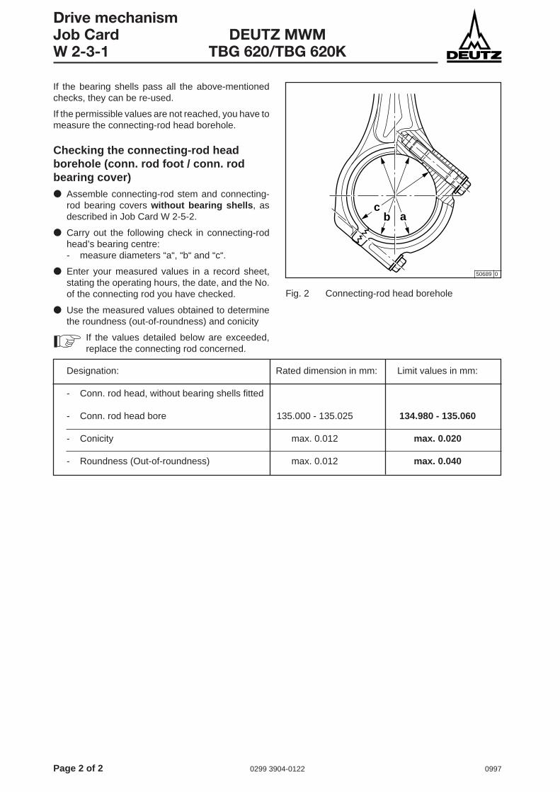
Page 2 of 2 0299 3904-0122 0997
Drive mechanismJob Card DEUTZ MWMW 2-3-1 TBG 620/TBG 620K
cb a
If the bearing shells pass all the above-mentionedchecks, they can be re-used.
If the permissible values are not reached, you have tomeasure the connecting-rod head borehole.
Checking the connecting-rod headborehole (conn. rod foot / conn. rodbearing cover)● Assemble connecting-rod stem and connecting-
rod bearing covers without bearing shells , asdescribed in Job Card W 2-5-2.
● Carry out the following check in connecting-rodhead’s bearing centre:- measure diameters “a“, “b“ and “c“.
● Enter your measured values in a record sheet,stating the operating hours, the date, and the No.of the connecting rod you have checked.
● Use the measured values obtained to determinethe roundness (out-of-roundness) and conicity
If the values detailed below are exceeded,replace the connecting rod concerned.
Designation: Rated dimension in mm: Limit values in mm:
- Conn. rod head, without bearing shells fitted
- Conn. rod head bore 135.000 - 135.025 134.980 - 135.060
- Conicity max. 0.012 max. 0.020
- Roundness (Out-of-roundness) max. 0.012 max. 0.040
50689 0
Fig. 2 Connecting-rod head borehole

0997 0299 3888-0122 Page 1 of 2
Drive mechanismDEUTZ MWM Job Card
TBG 620/TBG 620K W 2-5-1
Connecting rod bearings: removing
Tools:- Normal tools
Cross-references:- Job Card W 2-0-1, W 2-1-3, W 2-9-1
With piston removal● Turn the crankshaft so that connecting rod screws
1 can be loosened.
● Prop up the connecting rod bearing cover 2.
● Unscrew the connecting rod screws completely.
● Lift the connecting rod bearing cover out of thecrankcase.
● Take the bottom bearing shell out of the connectingrod bearing cover.
● If you are removing the piston (see Job CardW 2-9-1), take the top bearing shell out of theconnecting rod.
● Protect the crankshaft journal against soiling in theoil bore with adhesive tape (not with transparentsellotape), and wrap with a clean cloth or oiledpaper.
The safety instructions for work on thedrive mechanism must be complied withas detailed in Job Card W 2-0-1.
!
Without removing the pistonThe top bearing shell can be removed even while thepiston is still installed.
● Remove the connecting rod bearing cover 2 asdescribed under “Work sequence with piston rem-oval”.
● Slowly turn the piston with the crankshaft, until theconnecting rod is hanging free.
● Take off the top bearing shell.
50 746 0
Assessing the bearing shellssee Job Card W 2-1-3.
Fig. 1 Connecting rod bearing

Page 2 of 2 0299 3888-0122 0997
Drive mechanismJob Card DEUTZ MWMW 2-5-1 TBG 620/TBG 620K
This page intentionally left blank.
0997 0299 3889-0122 Page 1 of 2
Drive mechanismDEUTZ MWM Job Card
TBG 620/TBG 620K W 2-5-2
Connecting rod bearings: installing
Tools:- Normal tools
Cross-references:- Job Card W 2-0-1, W 2-1-3, W 2-14-1- Tightening Instructions
Assess bearing shells as described in JobCard W 2-1-3, and replace if necessary. Becareful not to get the bearing shells and bearingcovers mixed up. Piston, connecting rod footand bearing cover are all identified with thecylinder number involved. Check the conditionof the lift journal. Permissible run-out is0.020 mm. Consult DEUTZ Service beforeinitiating any rework if this becomes necessary.
The safety instructions for work on thedrive mechanism must be complied withas detailed in Job Card W 2-0-1.
!
PreparationClean all parts thoroughly.Check the surface condition of the lift journalmeticulously, and smooth out any impact points withan oil stone.
When the piston has been removed● Insert top bearing shell into the connecting rod,
and install piston as described in Job CardW 2-14-1.
Top and bottom shells are identical. Makesure that run bearing shells are fitted backinto their original positions, and that the groovecoincides with the fixing pin.
● Lower the connecting rod with piston slowly ontothe lift journal.
When the piston is still fitted● Insert the bearing shell into the connecting rod
foot, in the same way as when the piston has beenremoved. Turn the lift journal slowly into theconnecting rod foot.
● Insert bearing shell into the bearing cover. Oil thecontact surface of the bearing shell.
● Make sure that the rear of the bearing and thepartition lines are free from oil and grease.
● Fit the connecting rod cover, making sure that thefixing pin pressed into the connecting rod cover iscorrectly positioned.
● Oil the thread and the contact areas, tightenconnecting rod screws in accordance withTightening Instructions.
● Check clearance between crankshaft andconnecting rod bearing, max. 0.095...0.230 mm.
!
Comply with the tightening instructionsgiven in the Operating Manual,Chapter 8, „Technical Data“.
Page 2 of 2 0299 3889-0122 0997
Drive mechanismJob Card DEUTZ MWMW 2-5-2 TBG 620/TBG 620K
This page intentionally left blank.
0997 0299 3905-0122 Page 1 of 4
Drive mechanismDEUTZ MWM Job Card
TBG 620/TBG 620K W 2-9-3
Removing and installing the piston
When you replace a piston or the piston rings, youmust also replace the cylinder liner at the same timeif its wear limits have been exceeded. Cylinder linerswhich still have the right dimensions have to be re-honed.
Tools:- Normal tools- Lifting tackle- Lift-out plate- Piston support device- Tightening strap or mounting pliers
Aids:- Wooden wedges- Engine oil
Cross-references:- Job Card W 0-1-3, W 1-4-1, W 2-12-4
Removing the piston● Remove cylinder head,
see Job Card W 1-4-1.
● Remove inspection hole cover at the height of thecylinder concerned on the opposite row of cylinders.
● Using a scraper, carefully remove the oil carbondeposits at the top of the cylinder liner.
● Move the piston to its TDC position.
● Scrape free the cylinder number (if any) on thebottom of the piston.
If there is no cylinder number on the piston,mark the piston for identification before youremove it.
● Mark the connecting rod-cover with the cylindernumber.
● Unscrew the connecting-rod screws, and take offthe loose connecting-rod cover.
● Screw the lift-out plate onto the piston, detach theconnecting-rod from the crankshaft, and push itupwards.
● With the lift-off plate, pull out the piston andconnecting rod upwards.
Withdraw the piston carefully, taking care notto damage the connecting rod, the cylinderliner and the piston cooling spray jet.
Comply with the tightening instructionsgiven in the Operating Manual,Chapter 8, „Technical Data“.

Page 2 of 4 0299 3905-0122 0997
Drive mechanismJob Card DEUTZ MWMW 2-9-3 TBG 620/TBG 620K
Storing removed pistons
When you have removed the piston, eitherplace it inverted with the connecting rod usingtwo wooden wedges (Fig. 1 left), or store itsuspended in a wooden rack (Fig. 1 right).
Installing the piston● Coat piston, cylinder liner and connecting-rod
bearing shells with a generous amount of engineoil.
You must put each piston back into the samecylinder you took it out of.
● Before installing piston, check whether thebottom edge of the piston has been mountedwith its milled point on the side of the spray jet,see Job Card W 2-12-4.
● The joints of the piston rings must be offset againsteach other at installation by 180° or 90° respectively.Install the ring and spring joints of the narrow-landdrain oil-control ring offset by 180°, Fig. 2.
Installation with a tightening satrap● Use a tightening strap to clamp together all three
piston rings, Fig. 3.
● Carefully insert piston and connecting rod into thecylinder liner, until the tightening strap is flushagainst the top edge of the cylinder liner.
● Hold and guide the connecting rod from below, andpress the piston slowly downwards from above,until the connecting-rod bearing shell is resting onthe connecting-rod journal of the crankshaft.
50710 0
50702 0
50749 0
!
Fig. 1 Storing the pistons
Fig. 2 Piston ring configuration
Fig. 3 Piston installation with a tightening strap

0997 0299 3905-0122 Page 3 of 4
Drive mechanismDEUTZ MWM Job Card
TBG 620/TBG 620K W 2-9-3
Installation with mounting pliers● Use the mounting pliers to clamp all three piston
rings, Fig. 4.
● Carefully insert piston and connecting rod into thecylinder liner, until the mounting pliers are restingon the top edge of the cylinder liner.
● Hold and guide the connecting rod from below.
● Slightly loosen the mounting pliers at the tommyscrew, and press the piston slowly downwardsfrom above, until the connecting-rod bearing shellis resting on the connecting-rod journal of thecrankshaft.
The connecting rod must not be allowed toouch the spray nozzles, nor must it knockagainst the crankshaft. This would damagethe bearing journals, and bend the spray jets.
● Fit the connecting-rod bearing cover, making surethe fixing pin located in the connecting-rod bearingcover is correctly positioned.
● Oil the thread and the contact areas.
● Tighten the connecting-rod screws, with tighteningtorques as follows:
Step 1: 150 NmStep 2: 250 NmStep 3: 30°Step 4: 30°
● Check clearance between crankshaft andconnecting-rod bearing:
max. 0.095...0.230 mm.
● Fit inspection hole cover with new seal to thecrankcase.
● Fit cylinder head,see Job Card W 1-4-1.
When new pistons have been installed withrings and/or cylinder liners, you must run inyour engine anew,see Job Card W 0-1-3.
50701 0
!
Fig. 4 Piston installation with mounting pliers

Page 4 of 4 0299 3905-0122 0997
Drive mechanismJob Card DEUTZ MWMW 2-9-3 TBG 620/TBG 620K
This page intentionally left blank.

0997 0299 3903-0122 Page 1 of 2
Drive mechanismDEUTZ MWM Job Card
TBG 620/TBG 620K W 2-10-1
TOP
TOP
1
2
3
4
Removing and installing the piston rings
Every time a piston is removed, you must replace thepiston ring set. Only in exceptional cases, and aftermeticulous checking may you re-install piston ringsets.
Tools:- Piston ring pliers
Cross-references:- Job Card W 2-9-3, W 2-10-3
Removing the piston rings● Remove piston,
see Job Card W 2-9-3.
● Take off piston rings, using piston ring pliers,Fig. 1.
● Check piston ring groove and piston rings,see Job Card W 2-10-3.
Installing the piston rings● Use piston ring pliers to insert the piston rings.
“Top“ on the piston ring flanks facing upwards,Fig. 2.
● Insert hose spring 4 of the narrow-land oil controlring 3 in the piston ring groove, Fig. 2.
● Fit piston rings in the sequence 3, 2, 1, Fig. 2.
Install ring and spring joints of the narrow-landdrain oil control ring offset by 180°.
50694 0
50695 0
Fig. 1 Piston ring pliers
Fig. 2 Piston ring configuration

Page 2 of 2 0299 3903-0122 0997
Drive mechanismJob Card DEUTZ MWMW 2-10-1 TBG 620/TBG 620K
This page intentionally left blank.

0997 0299 3902-0122 Page 1 of 2
Drive mechanismDEUTZ MWM Job Card
TBG 620/TBG 620K W 2-10-3
Checking the piston ring grooves and piston rings
50618 1
50696 1
Tools:- Feeler gauge- Micrometer
Cross-references:- Job Card W 2-9-3, W 2-10-1
Checking the axial clearance● Remove the piston,
see Job Card W 2-9-3.
● Take the old piston rings off the piston, using a pairof piston ring pliers.
● Clean the piston ring groove.
● Fit new piston rings,see Job Card W 2-10-1.
● Check the axial clearance of the piston rings every45°, Fig. 1.
● When taking your measurements, press the pistonring against the bottom of the groove in the vicinityof the measuring point, Fig. 2.
If the permissible axial clearance is exceeded,then you have to replace the piston.
Dimensions for piston rings and piston ringgrooves,see next page.
Fig. 1 Measuring points for measuring the axialclearance
Fig. 2 Measuring procedure for measuring theaxial clearance

Page 2 of 2 0299 3902-0122 0997
Drive mechanismJob Card DEUTZ MWMW 2-10-3 TBG 620/TBG 620K
’’X‘‘
Checking the joint clearance● Insert the piston ring in its mounting position in the
cleaned, not-worn, top part of the cylinder liner.
Make sure that the piston ring is not tilted.
● Use the feeler gauge to measure the joint clearance“X“ between the two piston ring ends, Fig. 3.
If the maximum permissible joint clearance isexceeded on a particular piston ring, you mustreplace the entire piston ring set concerned.
Dimensions for piston rings and piston ringgrooves,see Page 2.
● Install piston,see Job Card W 2-9-3.
80185 0
Fig. 3 Piston ring joint clearance
Piston ring set1. Keystone ring
2. Tapered compression piston ring
3. Narrow-land drain oil control ring with hose spring
Dimensions for piston rings and piston ring grooves
Ring thickness and groove depth Joint clearance Axial clearance
As-new dimension As-new max. perm. As-new max. perm. condition condition
(mm) (mm) (mm) (mm) (mm)
Ring 3.313 - 3.333 0.50 - 0.75 1.20 1. 0.082 - 0.132 0.180
Groove 3.415 - 3.445 --- ---
Ring 3.475 - 3.490 0.90 - 1.15 1.50 2. 0.070 - 0.105 0.150
Groove 3.560 - 3.580 --- ---
Ring 5.975 - 5.990 0.50 - 0.80 1.00 3. 0.070 - 0.105 0.150
Groove 6.060 - 6.080 --- ---

0997 0299 3907-0122 Page 1 of 2
Drive mechanismDEUTZ MWM Job Card
TBG 620/TBG 620K W 2-12-2
Removing and installing the piston pin bush
Tools:- Normal tools- Press- Inside callipers- Micrometer
Aids:- Nitrogen
Cross-references:- Job Card W 0-3-1, W 2-12-4
Checking the● Remove piston pin,
see Job Card W 2-12-4.
● Check that the piston pin bushes are firmly seated.
● Check that the position of the oil bores in theconnecting-rod eye and the piston pin bush stillcoincide. (When a 6 mm test mandrel can nolonger be inserted, replace the bush).
● Check piston pin bush for even contact pattern,surface quality and scoring.
● Measure piston pin bush.
Replace any scored, worn connecting-rodbushes, or any with a poor contact pattern.
Tolerances Nominal dimension Wear limitin mm in mm
Piston bush Diameter 65.056...65.099 65.140after installation
Conicity after 65.060...65.120 65.140installation at rightangles to force direction 0.020
Conn. rod Clearance betweenpiston pin and pistonpin bush 0.056...0.107 0.120
Axial clearance betweenconn. rod and piston 0.180...0.740 1.000

Page 2 of 2 0299 3907-0122 0997
Drive mechanismJob Card DEUTZ MWMW 2-12-2 TBG 620/TBG 620K
Removing the piston pin bush● Grind in a continuous groove approx. 2.5 mm deep
on the long side of the bush (this will cause thebush to be detached).
● Use a press-out bush to press out the piston pinbush from the eye of ht connecting rod, Fig. 1.
Installing the piston pin bush● For how to work with liquid nitrogen,
see Job Card W 0-3-1.
● Warm up the connecting rod.
● Supercool the piston pin bush in liquid nitrogen(temperature difference required is approx. 200°C).
● Without using force, insert the piston pin bush.
Make sure the bush is correctly positioned inrelation to oil bores, oil pockets and lateralflushness at insertion.
The piston pin bushes are ready for installation,and must not be reworked after shrink-in.
● After installation, check the piston pin bushes.
● Install the piston pin,see Job Card W 2-12-4.
50748 0
Fig. 1 Pressing out with a press-out bush

0997 0299 3906-0122 Page 1 of 2
Drive mechanismDEUTZ MWM Job Card
TBG 620/TBG 620K W 2-12-4
Removing and installing the piston pin
Tools:- Normal tools- Pliers for circlips- Inside callipers- Micrometer
Aids:- Engine oil
Cross-references:- Job Card W 2-9-3
Removing the piston pin● Remove the piston,
see Job Card W 2-9-3.
● Clean the sides of the piston pin bore to removeany oil carbon.
● Remove the circlip in the piston, Fig. 1.
● Push the piston pin out of the piston, if necessarytapping it lightly with a piece of wood or a hammerhandle (no warm-up necessary).
Checking the piston pin clearance inthe piston● Use a micrometer to measure the diameter of the
piston pin.
● Use inside callipers to measure the piston pinbore.
The calculated clearance between piston pinand piston pin bore in the piston must notexceed 0.03 mm.
Checking the piston pin clearance inthe connecting-rod eye● Use a micrometer to measure the diameter of the
piston pin.
● Use inside callipers to measure the connecting-rod eye.
The calculated clearance between piston pinand connecting-rod eye bore must not exceed0.12 mm.
If the permissible tolerances have beenexceeded, the components concerned mustbe replaced.
50709 0
Fig. 1 Removing and installing the piston pincirclips

Page 2 of 2 0299 3906-0122 0997
Drive mechanismJob Card DEUTZ MWMW 2-12-4 TBG 620/TBG 620K
Installing the piston pin● Insert a circlip in the piston.
Position the opening of the circlip facingupwards, and make sure that the circlip isfirmly seated in the groove provided, Fig. 1.
● Oil all components abundantly.
When assembling the piston and theconnecting-rod together, take special note ofthe length of the recess for the spray jet at thebottom of the piston shaft. The recess for thespray jet 1 in Fig. 2 is located on the side of the“near-the-pin” connecting-rod ,screw.
The arrow marking 2 in Fig. 2 on the pistonpoints to the exhaust side.
● Insert the piston pin into the piston.
● Place the piston on the connecting rod, and pushin the piston pin as far as the circlip.
● Insert the circlip for the piston pin on the other sideof the piston.
Position the opening of the circlip facingupwards, and make sure that the circlip isfirmly seated in the groove provided, Fig. 1.
● Install piston,see Job Card W 2-9-3.
50747 0
!
!
Fig. 2 Piston alignment against connecting rod.
0997 0299 3908-0122 Page 1 of 4
Drive mechanismDEUTZ MWM Job Card
TBG 620/TBG 620K W 2-15-1
Checking, removing and installing the piston cooling-oil jets
Tools:- Normal tools- Lamp and mirror- Aligning tool for piston cooling oil jets
Cross-references:- Job Card W 2-9-3- Operating instructions, Chapter 8,
Tightening instructions
You have to remove the piston cooling-oil jets for anymajor overhauls or erection jobs, before all cylinderliners are removed. You must also remove them isthere is severe soiling due to damage, or if the lube oilcircuit is soiled. Removing these jets is not essentialif you are only going to be removing and installingindividual pistons, connecting rods and cylinder liners.
Removing the piston cooling oil jets● Remove the piston,
see Job Card W 2-9-3.
● Mark piston cooling-oil jets with the associatedcylinder number.
Make sure you do not get the piston cooling-oil jets mixed up.
● Unscrew the fixing screws of the piston cooling-oiljets.
The fixing screws here are self-locking types,which are difficult to loosen. If the hexagonsocket is damaged, the engine must bedismantled and the screw drilled out. Takecare not to use any worn tools.
● Carefully remove the piston cooling oil jets.
Cleaning the piston cooling-oil jets● Clean the piston cooling-oil jets with cleaning
agent, and rinse them through.
● Clean and rinse out the main oil line in the crankcase(accessible from the drive end).
Installing the piston cooling-oil jets● Insert the piston cooling-oil jets belonging to each
cylinder into the locating bushes.
● Tighten the new fixing screws.
Comply with the tightening instructionsgiven in the Operating Manual,Chapter 8, „Technical Data“.

Page 2 of 4 0299 3908-0122 0997
Drive mechanismJob Card DEUTZ MWMW 2-15-1 TBG 620/TBG 620K
Aligning the piston cooling-oil jets (with pistonremoved)● Place monitoring device 4 on cylinder liner.
The top plate is positioned by the coolingwater overspill hole 5 in the crankcase, andpossesses a monitoring hole 3 for the testmandrel 2.
● Insert test mandrel 2 carefully into spray jets 1.
The upper side of the test mandrel must befreely inserted into monitoring hole 3.
Fig. 1 Aligning the piston cooling-oil jets (with piston removed)
50750 0
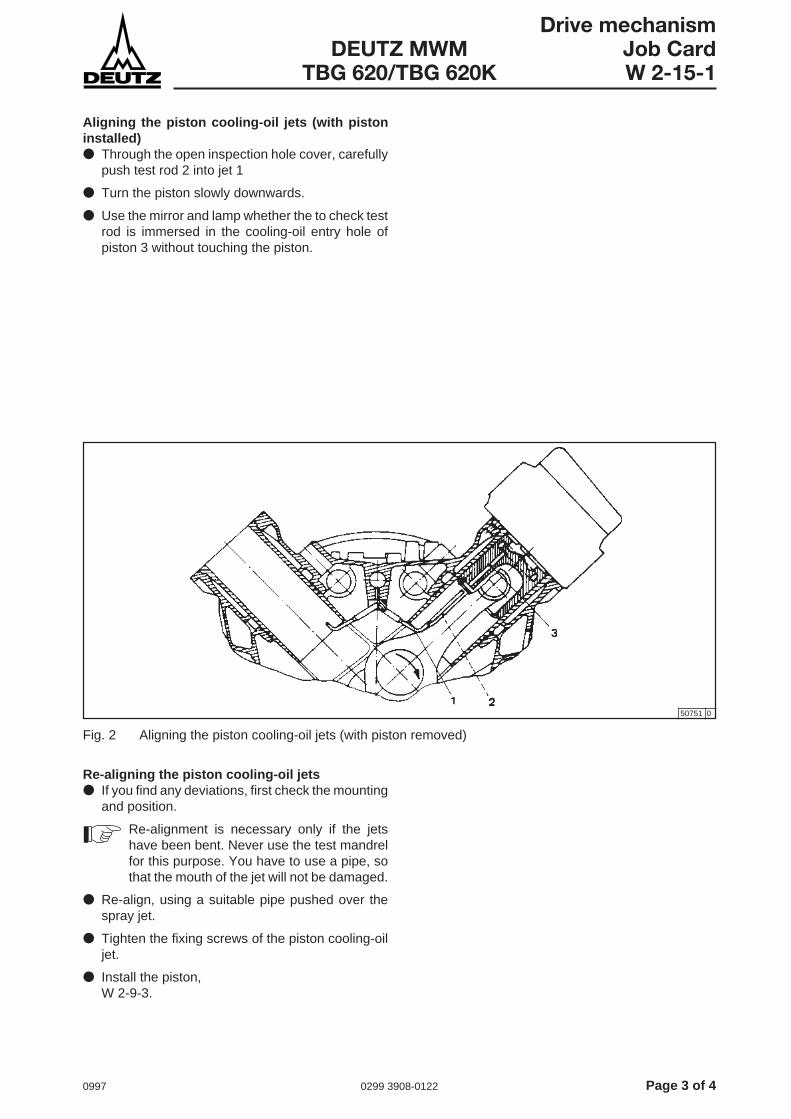
0997 0299 3908-0122 Page 3 of 4
Drive mechanismDEUTZ MWM Job Card
TBG 620/TBG 620K W 2-15-1
Aligning the piston cooling-oil jets (with pistoninstalled)● Through the open inspection hole cover, carefully
push test rod 2 into jet 1
● Turn the piston slowly downwards.
● Use the mirror and lamp whether the to check testrod is immersed in the cooling-oil entry hole ofpiston 3 without touching the piston.
Fig. 2 Aligning the piston cooling-oil jets (with piston removed)
Re-aligning the piston cooling-oil jets● If you find any deviations, first check the mounting
and position.
Re-alignment is necessary only if the jetshave been bent. Never use the test mandrelfor this purpose. You have to use a pipe, sothat the mouth of the jet will not be damaged.
● Re-align, using a suitable pipe pushed over thespray jet.
● Tighten the fixing screws of the piston cooling-oiljet.
● Install the piston,W 2-9-3.
50751 0

Page 4 of 4 0299 3908-0122 0997
Drive mechanismJob Card DEUTZ MWMW 2-15-1 TBG 620/TBG 620K
This page intentionally left blank.

0997 0299 3910-0122 Page 1 of 2
CrankcaseDEUTZ MWM Job Card
TBG 620/TBG 620K W 3-3-1
Measuring the cylinder liner
Tools:- Inside micrometer- Turning device
Cross-references:- Job Card W 1-4-4, W 2-0-1, W 3-3-3
Mesuring the cylinder liner● Remove the cylinder head,
see Job Card W 1-4-4.
● Turn the crankshaft until the piston concerned is atits BDC position.
● Clean the cylinder liner to remove any combustionresidues.
● Check the stop edge of the first piston ring.
If it can be clearly felt, this means there isexcessive wear.
● Set the inside micrometer to the inside diameter ofthe cylinder liner.
● Take your measurements in accordance with themeasurement sheet attached, in longitudinal andtransverse directions, and in the different measuringlevels.
Nominal diameter Ø 170 +0.025 mm
max. perm. wear dimension Ø 170.340 mm
max. perm. out-of-roundness 0.051 mm
Fig. 1 Stop edge of the first piston ring
Fig. 2 Measuring with an inside micrometer
24873 1
50657 0
The safety instructions for work on thedrive mechanism must be complied withas detailed in Job Card W 2-0-1.
!
If one of the max. permissible values isexceeded, you must replace the cylinderliner concerned,see Job Card W 3-3-3.
If the cylinder liner is only slightly worn, itmay be possible to re-hone it. If you areconsidering this option, please contact yourDEUTZ Service.
● Fit the cylinder head,see Job Card W 1-4-4.
Table 1 Cylinder liner dimensions

Page 2 of 2 0299 3910-0122 0997
CrankcaseJob Card DEUTZ MWMW 3-3-1 TBG 620/TBG 620K
Mea
sure
met
n sh
eet f
or c
ylin
der
liner
s ø
170
+0
.025
mm
(no
min
al d
imen
sion
)C
usto
mer
:E
ngin
e ty
pe:
Op.
hou
rs:
Dat
e:
Eng
ine
No.
:O
rder
No.
:M
easu
red:
(Nam
e) Cou
plin
g en
dC
ylin
der:
A1
A2
A3
A4
A5
A6
A7
A8
Mea
s. d
irect
ion
XY
XY
XY
XY
XY
XY
XY
XY
H in
mm
35
50 150
250
Cyl
inde
r:B
1B
2B
3B
4B
5B
6B
7B
8
Mea
s. d
irect
ion
XY
XY
XY
XY
XY
XY
XY
XY
H in
mm
35
50 150
250
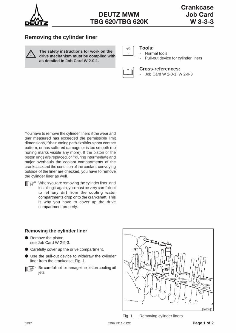
0997 0299 3911-0122 Page 1 of 2
CrankcaseDEUTZ MWM Job Card
TBG 620/TBG 620K W 3-3-3
Removing the cylinder liner
Tools:- Normal tools- Pull-out device for cylinder liners
Cross-references:- Job Card W 2-0-1, W 2-9-3
You have to remove the cylinder liners if the wear andtear measured has exceeded the permissible limitdimensions, if the running path exhibits a poor contactpattern, or has suffered damage or is too smooth (nohoning marks visible any more). If the piston or thepiston rings are replaced, or if during intermediate andmajor overhauls the coolant compartments of thecrankcase and the condition of the coolant-conveyingoutside of the liner are checked, you have to removethe cylinder liner as well.
When you are removing the cylinder liner, andinstalling it again, you must be very careful notto let any dirt from the cooling watercompartments drop onto the crankshaft. Thisis why you have to cover up the drivecompartment properly.
Removing the cylinder liner● Remove the piston,
see Job Card W 2-9-3.
● Carefully cover up the drive compartment.
● Use the pull-out device to withdraw the cylinderliner from the crankcase, Fig. 1.
Be careful not to damage the piston cooling oiljets.
Fig. 1 Removing cylinder liners
50708 0
The safety instructions for work on thedrive mechanism must be complied withas detailed in Job Card W 2-0-1.
!

Page 2 of 2 0299 3911-0122 0997
CrankcaseJob Card DEUTZ MWMW 3-3-3 TBG 620/TBG 620K
This page intentionally left blank.
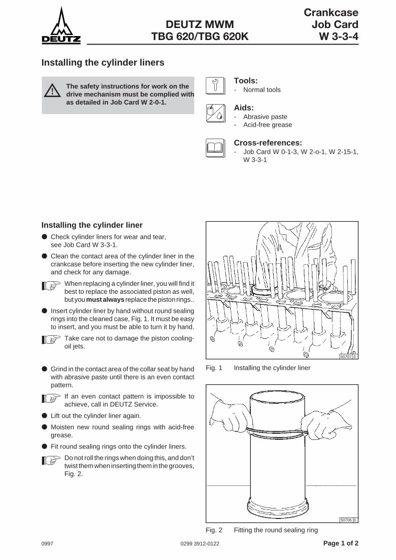
0997 0299 3912-0122 Page 1 of 2
CrankcaseDEUTZ MWM Job Card
TBG 620/TBG 620K W 3-3-4
Installing the cylinder liners
Tools:- Normal tools
Aids:- Abrasive paste- Acid-free grease
Cross-references:- Job Card W 0-1-3, W 2-o-1, W 2-15-1,
W 3-3-1
Installing the cylinder liner● Check cylinder liners for wear and tear,
see Job Card W 3-3-1.
● Clean the contact area of the cylinder liner in thecrankcase before inserting the new cylinder liner,and check for any damage.
When replacing a cylinder liner, you will find itbest to replace the associated piston as well,but you must always replace the piston rings..
● Insert cylinder liner by hand without round sealingrings into the cleaned case, Fig. 1. It must be easyto insert, and you must be able to turn it by hand.
Take care not to damage the piston cooling-oil jets.
● Grind in the contact area of the collar seat by handwith abrasive paste until there is an even contactpattern.
If an even contact pattern is impossible toachieve, call in DEUTZ Service.
● Lift out the cylinder liner again.
● Moisten new round sealing rings with acid-freegrease.
● Fit round sealing rings onto the cylinder liners.
Do not roll the rings when doing this, and don’ttwist them when inserting them in the grooves,Fig. 2.
50707 0
50706 0
Fig. 1 Installing the cylinder liner
The safety instructions for work on thedrive mechanism must be complied withas detailed in Job Card W 2-0-1.
!
Fig. 2 Fitting the round sealing ring

Page 2 of 2 0299 3912-0122 0997
CrankcaseJob Card DEUTZ MWMW 3-3-4 TBG 620/TBG 620K
● Insert the cylinder liner by hand as far as thecontact area.
Every cylinder liner is punch-marked at thetop collar with the DEUTZ-MWM lettering.Install the liner with this lettering facing theshock-absorber rod side, Fig. 3.
Whenyou are installing the cylinder liner, takecare not to damage the piston cooling-oil jets.
● Check the alignment of the piston cooling-oil jets,Fig. W 2-15-1.
● Use and installation device to push in the cylinderliners evenly with the round sealing rings, Fig. 4.
When you are installing the cylinder liners,there is a risk that the O-rings will jam or gettwisted. So be very careful when installing thecylinder liners.
● Install the piston,see Job Card W 2-9-3.
● After installing new cylinder liners and/or pistonsand piston rings, you must run in your engineanew,see Job Card W 0-1-3.
50705 0
50704 0
Fig. 3 Identification on the cylinder liners
Fig. 4 Cylinder liner installation device

0997 0299 3909-0122 Page 1 of 2
CrankcaseDEUTZ MWM Job Card
TBG 620/TBG 620K W 3-7-1
Foundation bolts
Tools:- Normal tools
Since the foundation may alter, due to the effects ofheat and distortion, you have to check the foundationbolts to see if they have worked loose. This isparticularly important after the first few operatinghours.
Checking the foundation bolts● Check adapters in the case of a rigid mounting, or
shims in the case of elastic mounting, by tapping(include the places where pipes above make accessdifficult).
When you tap, a metallic sound is an indicationof a secure join.
● Tighten loose screws, following the manufacturer’stightening instructions.
● Check the alignment.
Make sure everything is kept meticulouslyclean; in particular, keep oil and water awayfrom the foundation.

Page 2 of 2 0299 3909-0122 0997
CrankcaseJob Card DEUTZ MWMW 3-7-1 TBG 620/TBG 620K
This page intentionally left blank.

0997 0299 3509-0122 Page 1 of 2
Engine controlDEUTZ MWM Job Card
TBG 620/TBG 620K W 4-1-1
Removing and installing the camshaft bearings
Tools:- Normal tools- Press-out device- Two-step measuring instrument
Cross-references:- Job Card W 2-0-1, W 4-5-1, W 4-5-2
You must replace the camshaft bearings if after avisual inspection or taking measurements you discoverwear and tear.
Removing the camshaft bearings● Remove the camshaft bearings,
see Job Card W 4-5-1.
Checking the camshaft bearings● Check bearing bushes for scoring and wear.
Dimensions in mm Nominal dimension Wear limit
Location holein crankcase 68,000...68,030 68.035
Camshaft bush pressed in,inner diameter 59.996...60.050 60.120
Brg clearance, camshaft - brg 0.064...0.156 0.240
● Fit press-out device 1.
● Withdraw bearing bush 2 form crankcase 3.
50323 0
Cleaning the components● After removing scored or worn bearing bushes,
clean all the oil boreholes very carefully, preferablywith compressed air.
If, because of reworking at the crankcase ordue to bearing damage, metal chips havepenetrated into the oil circuit or into thecrankcase, then you must remove thecamshaft bearing bushes (even if there isnothing wrong with them), and clean the oilborehole and the oil grooves. It is then best topress in new bearing bushes.
The safety instructions for work on thedrive mechanism must be complied withas detailed in Job Card W 2-0-1.
!
Table 1 Nominal dimensions and wear limits
Fig. 1 Withdrawing the camshaft bearings
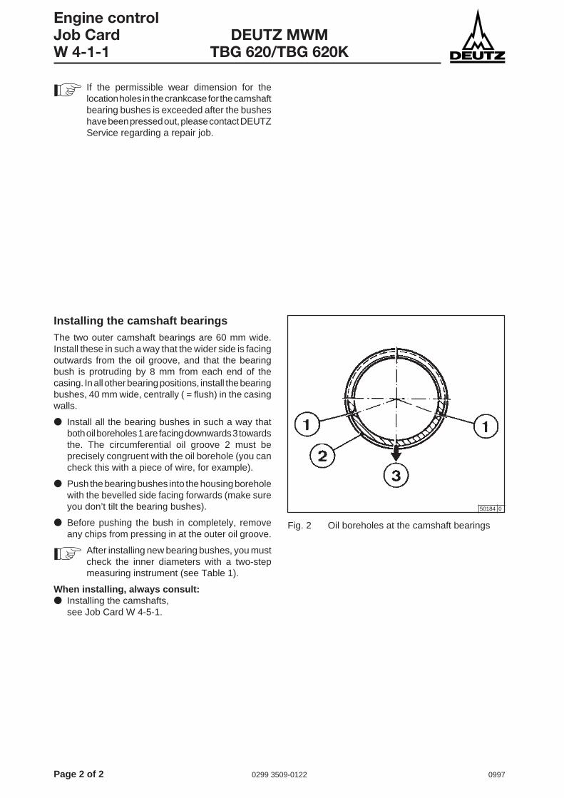
Page 2 of 2 0299 3509-0122 0997
Engine controlJob Card DEUTZ MWMW 4-1-1 TBG 620/TBG 620K
If the permissible wear dimension for thelocation holes in the crankcase for the camshaftbearing bushes is exceeded after the busheshave been pressed out, please contact DEUTZService regarding a repair job.
50184 0
Installing the camshaft bearingsThe two outer camshaft bearings are 60 mm wide.Install these in such a way that the wider side is facingoutwards from the oil groove, and that the bearingbush is protruding by 8 mm from each end of thecasing. In all other bearing positions, install the bearingbushes, 40 mm wide, centrally ( = flush) in the casingwalls.
● Install all the bearing bushes in such a way thatboth oil boreholes 1 are facing downwards 3 towardsthe. The circumferential oil groove 2 must beprecisely congruent with the oil borehole (you cancheck this with a piece of wire, for example).
● Push the bearing bushes into the housing boreholewith the bevelled side facing forwards (make sureyou don’t tilt the bearing bushes).
● Before pushing the bush in completely, removeany chips from pressing in at the outer oil groove.
After installing new bearing bushes, you mustcheck the inner diameters with a two-stepmeasuring instrument (see Table 1).
When installing, always consult:● Installing the camshafts,
see Job Card W 4-5-1.
Fig. 2 Oil boreholes at the camshaft bearings

0997 0299 3913-0122 Page 1 of 2
Engine controlDEUTZ MWM Job Card
TBG 620/TBG 620K W 4-2-1
Removing, installing and checking the bottom valve mechanism
Tools:- Normal tools
Cross-references:- Job Card W 1-2-2, W 1-4-4, W 2-0-1
Removing the shock-absorber rods● Remove valve lifter,
see Job Card W 1-2-2.
● Take out shock-absorber rods upwards.
50755 1
Checking the shock-absorber rods● Check the shock-absorber rods for run-out by
always turning two of them next to each other.
● Check shock-absorber rod head (ball socket) andshock-absorber rod foot (ball head) for wear andtear or damage (break-outs, etc.).
Installing the shock-absorber rods● Insert the shock-absorber rods carefully from
above.
● Install valve lifter,see Job Card W 1-2-2.
The safety instructions for work on thedrive mechanism must be complied withas detailed in Job Card W 2-0-1.
!
Fig. 1 Valve tappet with shock-absorber rod

Page 2 of 2 0299 3913-0122 0997
Engine controlJob Card DEUTZ MWMW 4-2-1 TBG 620/TBG 620K
Removing the valve tappet● Remove the cylinder head,
see Job Card W 1-4-4.
● Take out the shock-absorber rods upwards.
● Remove the shock-absorber rod guard sheaths.
● Take out the valve tappet from the holes in thecrankcase.
Checking the valve tappet● Check the valve tappet’s contact area and inner
seat pan for wear and tear.
● Check the holes at the bottom end of the tappet forfree passage, Fig. 1.
If you find irregularities when you check thetappets, then check the camshafts andcamshaft bearings as well.
Installing the valve tappet● Insert valve tappet into the holes of the crankcase.
● Carefully install shock-absorber rod guard sheathswith new sealing rings.
● Insert shock-absorber rods carefully from above.
● Fit cylinder head,see Job Card W 1-4-4.
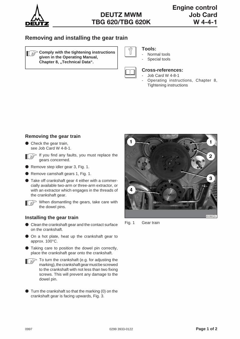
0997 0299 3933-0122 Page 1 of 2
Engine controlDEUTZ MWM Job Card
TBG 620/TBG 620K W 4-4-1
Removing and installing the gear train
Tools:- Normal tools- Special tools
Cross-references:- Job Card W 4-8-1- Operating instructions, Chapter 8,
Tightening instructions
Removing the gear train● Check the gear train,
see Job Card W 4-8-1.
If you find any faults, you must replace thegears concerned.
● Remove step idler gear 3, Fig. 1.
● Remove camshaft gears 1, Fig. 1.
● Take off crankshaft gear 4 either with a commer-cially available two-arm or three-arm extractor, orwith an extractor which engages in the threads ofthe crankshaft gear.
When dismantling the gears, take care withthe dowel pins.
Installing the gear train● Clean the crankshaft gear and the contact surface
on the crankshaft.
● On a hot plate, heat up the crankshaft gear toapprox. 100°C.
● Taking care to position the dowel pin correctly,place the crankshaft gear onto the crankshaft.
To turn the crankshaft (e.g. for adjusting themarking), the crankshaft gear must be screwedto the crankshaft with not less than two fixingscrews. This will prevent any damage to thedowel pin.
81060 0
Fig. 1 Gear train
● Turn the crankshaft so that the marking (0) on thecrankshaft gear is facing upwards, Fig. 3.
Comply with the tightening instructionsgiven in the Operating Manual,Chapter 8, „Technical Data“.
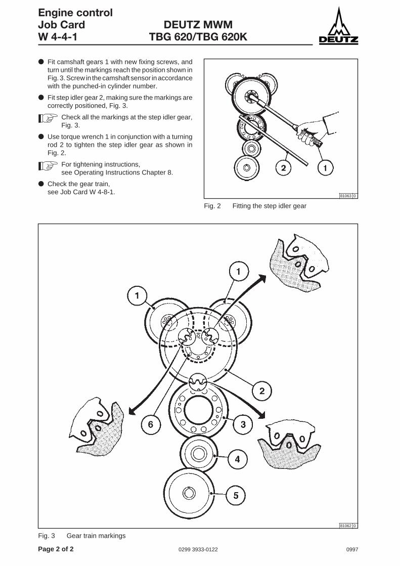
Page 2 of 2 0299 3933-0122 0997
Engine controlJob Card DEUTZ MWMW 4-4-1 TBG 620/TBG 620K
81062 0
● Fit camshaft gears 1 with new fixing screws, andturn until the markings reach the position shown inFig. 3. Screw in the camshaft sensor in accordancewith the punched-in cylinder number.
● Fit step idler gear 2, making sure the markings arecorrectly positioned, Fig. 3.
Check all the markings at the step idler gear,Fig. 3.
● Use torque wrench 1 in conjunction with a turningrod 2 to tighten the step idler gear as shown inFig. 2.
For tightening instructions,see Operating Instructions Chapter 8.
● Check the gear train,see Job Card W 4-8-1.
81063 0
Fig. 2 Fitting the step idler gear
Fig. 3 Gear train markings

0997 0299 3507-0122 Page 1 of 2
Engine controlDEUTZ MWM Job Card
TBG 620/TBG 620K W 4-5-1
Removing, checking the camshaft
Tools:- Normal tools- Insertion and removal mandrels for
camshaft- Prism / dial gauge- Micrometer
Cross-references:- Job Card W 2-0-1, W 4-1-1, W 4-2-1,
W 4-4-1
You will not normally need to check the camshafts,their bearings and their drive mechanism until a majoroverhaul becomes due, unless a check on the valvetappets has discovered some irregularities.
Removing the camshafts● Remove bottom valve mechanism,
see Job Card W 4-2-1.
● Remove camshaft drive gears,see Job Card W 4-4-1.
● Remove guide plates of camshafts 1, Fig. 1.
● Fit removal mandrel to the camshaft, Fig. 2.
● Carefully withdraw camshaft from the crankcase.
50698 0
The safety instructions for work on thedrive mechanism must be complied withas detailed in Job Card W 2-0-1.
!
Chekcing the camshaft bearings● Give camshafts’ bearing shells in crankcase a
visual inspection. Replace any worn bearing shells,see Job Card W 4-1-1.
Fig. 1 Camshaft guide plates
Fig. 2 Removal mandrel for the camshaft
81064 0
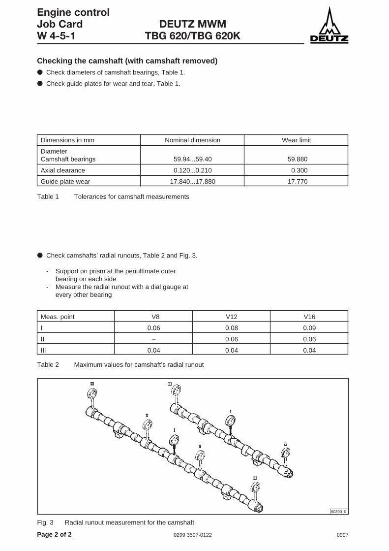
Page 2 of 2 0299 3507-0122 0997
Engine controlJob Card DEUTZ MWMW 4-5-1 TBG 620/TBG 620K
Checking the camshaft (with camshaft removed)● Check diameters of camshaft bearings, Table 1.
● Check guide plates for wear and tear, Table 1.
Dimensions in mm Nominal dimension Wear limit
DiameterCamshaft bearings 59.94...59.40 59.880
Axial clearance 0.120...0.210 0.300
Guide plate wear 17.840...17.880 17.770
● Check camshafts’ radial runouts, Table 2 and Fig. 3.
- Support on prism at the penultimate outerbearing on each side
- Measure the radial runout with a dial gauge atevery other bearing
Meas. point V8 V12 V16
I 0.06 0.08 0.09
II – 0.06 0.06
IIl 0.04 0.04 0.04
50300 0
Fig. 3 Radial runout measurement for the camshaft
Table 1 Tolerances for camshaft measurements
Table 2 Maximum values for camshaft’s radial runout
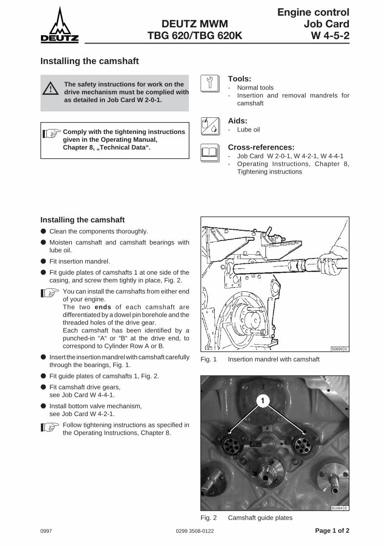
0997 0299 3508-0122 Page 1 of 2
Engine controlDEUTZ MWM Job Card
TBG 620/TBG 620K W 4-5-2
Installing the camshaft
Tools:- Normal tools- Insertion and removal mandrels for
camshaft
Aids:- Lube oil
Cross-references:- Job Card W 2-0-1, W 4-2-1, W 4-4-1- Operating Instructions, Chapter 8,
Tightening instructions
Installing the camshaft● Clean the components thoroughly.
● Moisten camshaft and camshaft bearings withlube oil.
● Fit insertion mandrel.
● Fit guide plates of camshafts 1 at one side of thecasing, and screw them tightly in place, Fig. 2.
You can install the camshafts from either endof your engine.The two ends of each camshaft aredifferentiated by a dowel pin borehole and thethreaded holes of the drive gear.Each camshaft has been identified by apunched-in “A“ or “B“ at the drive end, tocorrespond to Cylinder Row A or B.
● Insert the insertion mandrel with camshaft carefullythrough the bearings, Fig. 1.
● Fit guide plates of camshafts 1, Fig. 2.
● Fit camshaft drive gears,see Job Card W 4-4-1.
● Install bottom valve mechanism,see Job Card W 4-2-1.
Follow tightening instructions as specified inthe Operating Instructions, Chapter 8.
50699 0
The safety instructions for work on thedrive mechanism must be complied withas detailed in Job Card W 2-0-1.
!
81064 0
Fig. 1 Insertion mandrel with camshaft
Fig. 2 Camshaft guide plates
Comply with the tightening instructionsgiven in the Operating Manual,Chapter 8, „Technical Data“.

Page 2 of 2 0299 3508-0122 0997
Engine controlJob Card DEUTZ MWMW 4-5-2 TBG 620/TBG 620K
This page intentionally left blank.

0997 0299 3932-0122 Page 1 of 2
Engine controlDEUTZ MWM Job Card
TBG 620/TBG 620K W 4-8-1
Checking the gear train
Tools:- Normal tools- Feeler gauge- Dial gauge
Cross-references:- Job Card W 2-0-1, W 4-4-1, W 12-1-4
Checking the gear train● Take off the built-in parts at the free side of the
engine.
● Remove any vibration absorbers,see Job Card W 12-1-4.
● Remove the end wall cover.
Checking the gears● Visually inspect all spur gears for face wear and
pitting. If there is sever wear and tear (perceptiblewear), major pitting, damage to teeth, cracks at thetooth root, etc., replace the spur gears involved. Ifyou observe uneven contact patterns, check thatthe gear concerned is firmly secured, check thatthe flanged shafts are firmly secured in the case ofidler gear mountings, and check for faultlessconcentricity (axial and radial runout).
Checking the face clearance● Before removing the gears, and after finishing
assembly, check the face clearance at all gears.Use the feeler gauge to do this, checking whetherthe face clearance exceeds the wear limit value.
● If the wear limit value has been exceeded,replace the gear(s) concerned,see Job Card W 4-4-1.
● Fit end wall cover.
● Fit any vibration absorbers,see Job Card W 12-1-4.
● Fit built-on parts to the free side of the engine.
Meas. point Nominal dimension Wear limit
Face clearance 0.050...0.300 0.380
Idler gear axle Ø 44.959...44.975 Ø 44.955
Radial clearanceIdler gear axle -bearing bush 0.035...0.091 0.100
Axial clearance 0.080...0.192 0.300
Idler gear axle Ø 34.959...34.975 Ø 34.955
Radial clearanceIdler gear axle -bearing bush 0.025...0.083 0.120
[mm]
Lube oil pumps idlergear
The safety instructions for work on thedrive mechanism must be complied withas detailed in Job Card W 2-0-1.
!
Step idler gear
Table 1

Page 2 of 2 0299 3932-0122 0997
Engine controlJob Card DEUTZ MWMW 4-8-1 TBG 620/TBG 620K
This page intentionally left blank.

0997 0299 3934-0122 Page 1 of 2
GovernorDEUTZ MWM Job Card
TBG 620/TBG 620K W 5-3-13
Removing, installing and checking the frequency generator
Tools:- Normal tools- Feeler gauge
If the distance between the frequency generator andthe flywheel’s toothed rim is not adjusted correctly, orif there are chips of metal adhering to the permanentmagnets, this will affect the pulses fed to the controlelectronics. The frequency generator has been set inthe factory, and so you should never dismount itwithout a really good reason.
Removing the frequency generator● Loosen knurled nut 3 and disconnect the cable
link.
● Loosen counternut 2, and unscrew frequencygenerator 1 by hand.
● Check frequency generator for any metal chipsadhering and for soiling, and clean as necessary.
Installing the frequency generator● Screw in frequency generator 1 by hand until it is
just touching a tooth tip of the toothed rim 4 or thepulse protrusion of the flywheel, Fig. 1.
● To adjust the clearance “X“, turn the frequencygenerator back by 180° (1/2 a revolution), andtighten the counternut 2 (the position of thefrequency generator must not change when youdo this).
● Use a feeler gauge to check the clearance of thefrequency generator: “X“ 0.5 to 0.8 mm.
● Establish cable link with knurled nut 3.
50758 0
Fig. 1 Screw in until it touches
Fig. 2 Distance X after turning backwards
81073 0
Page 2 of 2 0299 3934-0122 0997
GovernorJob Card DEUTZ MWMW 5-3-13 TBG 620/TBG 620K
This page intentionally left blank.

0997 0299 3935-0122 Page 1 of 2
Exhaust gas system/ChargingDEUTZ MWM Job Card
TBG 620/TBG 620K W 6-4-1
Cleaning the mixture cooler on the water side
Tools:- Normal tools- Round brush- Wooden rod
Spare parts:- Seals and spring washers
Cross-references:- Job Card W 6-4-2, W 9-0-1- Operating Instructions, Chapter 4
You can carry out this cleaning routine while themixture cooler is still built on. If it is severely soiled,however, you have to remove it, and give it an additio-nal cleaning as described in Job Card W 6-4-2.Replace all seals, round sealing rings and the springwashers.
Cleanign the mixture cooler● Drain the engine,
see Job Card W 9-0-1.
● Close off all engine openings in the vicinity.
● Cover up all parts sensitive to water.
● Remove coolant lines tot he mixture cooler.
● Remove covers 1 and 3.
● Use a brush or a wooden rod to clean the inside(cooler insert 2).
● After you have finished your cleaning routine, fitthe covers.
● Fit the coolant lines.
● Fill up with coolant,see Operating Instructions Chapter 4.
50760 0
Fig. 1 Mixture cooler

Page 2 of 2 0299 3935-0122 0997
Exhaust gas system/ChargingJob Card DEUTZ MWMW 6-4-1 TBG 620/TBG 620K
This page intentionally left blank.

0997 0299 3936-0122 Page 1 of 2
Exhaust gas system/ChargingDEUTZ MWM Job Card
TBG 620/TBG 620K W 6-4-2
Cleaning the mixture cooler on the air side
Tools:- Normal tools- Lifting tackle- Cleaning agent
Spare parts:- Seals and spring washers
Cross-references:- Job Card W 6-4-1- Operating Instructions Chapter 4
Cleaning the mixture cooler● Take off the parts built onto the mixture cooler.
● Remove the mixture cooler.
● Clean the mixture cooler on the water side,see Job Card W 6-4-1.
● Use cleaning agent to wash out the mixture cooleron the air side, following the manufacturer’sinstructions.
● Rinse with a powerful jet of water, and blow drywith compressed air.
● Assemble mixture cooler, with new seals, roundsealing rings, and spring washers.
● Fill up with coolant,see Operating Instructions Chapter 4.

Page 2 of 2 0299 3936-0122 0997
Exhaust gas system/ChargingJob Card DEUTZ MWMW 6-4-2 TBG 620/TBG 620K
This page intentionally left blank.

0997 0299 3955-0122 Page 1 of 2
Lube oil systemDEUTZ MWM Job Card
TBG 620/TBG 620K W 8-11-2
Oil pressure control valve, removing, installing and checking
Tools:- Normal tools- Special wrench for removing the oil
pressure control valve- Measuring tools
Cross-references:- Job Card W 4-4-1
If the lube oil pressure drops, you must check the oilpressure control valve.
Removing the oil pressure control valve● Remove the gear train,
see Job Card W 4-4-1.
● Remove mounting 1 of oil pressure control valve,Fig. 1.
● Use special wrench to unscrew oil pressure controlvalve.
● Remove clamping cone pieces 3, Fig. 2.
● Dismantle oil pressure control valve, and clean allcomponents.
Always ensure absolute cleanliness whenworking on the lube oil system.
Checking the oil pressure control valve● Check the condition of the valve disk, the valve
seat in the housing, the clamping cone pieces, thespring plate, the valve stem and the valve spring.If you find any wear and tear, replace the partsconcerned.
Opening oil pressure control valve: 4 ± 0.3 bar.
Spring length 2 (destressed): 100 mm.
Clearance between valve 1 andvalve housing 4 max.: 0.085 mm.
Disc edge thickness of valve min.: 1.500 mm.
Spring power for an overall lengthof 58 mm: 28.2 ± 2.5 kp.
Installing the oil pressure control valve● To install, proceed in the opposite sequence.
When re-assembling, make sure the clampingcone pieces are correctly fitted, Fig. 2.
81065 0
Fig. 1 Oil pressure control valve mounting

Page 2 of 2 0299 3955-0122 0997
Lube oil systemJob Card DEUTZ MWMW 8-11-2 TBG 620/TBG 620K
50776 0
Fig. 2 Oil pressure control valve

0997 0299 3937-0122 Page 1 of 2
Coolant systemDEUTZ MWM Job Card
TBG 620/TBG 620K W 9-0-1
Draining the coolant system
Tools:- Normal tools
Aids:- Collecting containers for coolant
Cross-references:- Operating Instructions, Chapter 4- Operating Instructions, Chapter 7
For various jobs, such as those involving cylinderhead, crankcase, heat exchanger and piping, it isnecessary to drain off part or all of the coolant.
If no antifreeze has been added, then if your engine isgoing to be shut down for a lengthy period, and if thereis a risk of frost, then all the coolant must be drainedout of the engine and the built-on components.
If your engine is going to be shut down for a lengthyperiod, you must conserve it as detailed in theOperating Instructions, Chapter 7.
Draining off the coolant● Shut off the coolant lines to and from your engine.
● Place collecting containers to catch the coolant.
● Open the drain plug at the lube oil heat exchanger.
● Open the preheater drain plug 1, Fig. 1.
81068 0
81072 0
Fig. 1 Preheater drain plug
Fig. 2 Coolant pipe drain plug
● Open the coolant pipe drain plug 1, Fig. 2.

Page 2 of 2 0299 3937-0122 0997
Coolant systemJob Card DEUTZ MWMW 9-0-1 TBG 620/TBG 620K
● Open crankcase drain plugs. Fig. 3 shows thedrain plug 1 on the right-hand side.
81069 0
81070 0
● Open mixture cooler drain plugs 1.
After all the coolant has drained off, close the drainplugs, drain valves and pipes again. Use new sealsand sealing rings. Re-use the coolant you havecollected, or dispose of it in a eco-friendly manner.
Fig. 3 Crankcase drain plug
Fig. 4 Mixture cooler drain plugs

0997 0299 3938-0122 Page 1 of 2
Coolant systemDEUTZ MWM Job Card
TBG 620/TBG 620K W 9-9-1
Removing and installing the coolant preheater
Tools:- Normal tools
Aids:- Cleaning agent for removing scale- Collecting container for coolant
Depending on the type of engine involved, either oneor two heating element assemblies are installed. Ifonly these are to be cleaned, it is sufficient to removethem from the preheater housing.
Removing the coolant preheater● Switch off the power supply to the heating element
assembly 7.
● Disconnect the power cable from the heatingelement assembly.
● Close valves 1 and 3 in the lines to the crankcase’scoolant compartment.
● Unscrew coolant drain plug 5 , and collect thecoolant.
● Detach hose links 2 and 4.
● Remove the fixing screws of the preheater 6, andtake out the preheater unit.
● Remove the heating element assembly.
Installing the coolant preheater● Insert the preheater, and install the fixing screws.
● Attach hose links 2 and 4.
● Screw in coolant drain plug 5 with a new seal.
● Open valves 1 and 3 in the lines to the crankcase’scoolant compartment.
● Check the preheater for leaks.
● Check the coolant level, and top up with coolant ifnecessary.
Cleaning● Immerse the heating elements in a bath with a
scale-dissolving agent, until the lime scale hasbecome detached. Make sure the solventconcerned does not attack metal!.
NEVER use tools (e.g. scrapers) or force todetach these deposits.
● After you have cleaned them, rub the heatingelements down, and rinse them in clean water, toensure that no solvent gets into your engine’scoolant system.

Page 2 of 2 0299 3938-0122 0997
Coolant systemJob Card DEUTZ MWMW 9-9-1 TBG 620/TBG 620K
81071 0
Fig. 1 Preheater
0997 0299 3939-0122 Page 1 of 2
Other componentsDEUTZ MWM Job Card
TBG 620/TBG 620K W 12-1-4
Removing and fitting the torsional vibration damper
50784 0
Tools:- Normal tools- Lifting tackle
Aids:- Locking compound Omnifit 250M- Acid-free grease- Molykote or equivalent
Spare parts:- Round sealing rings
Cross-references:- Job Card W 2-0-1- Operating Instructions, Chapter 8,
Tightening Instructions
Check the exterior of the damper for oil leaks (radialtraces of oil on the side plates!). Repair the damper ofthe leaks are being caused by worn round sealingrings. For any further repairs, you must call in DEUTZService or the manufacturer.
Removing the torsional vibrationdamper● Remove the protective casing.
● Suspend the damper from the lifting tackle.
● Unscrew the fixing screws 5 to the crankshaft.
● Loosen the main connecting screws 8.
● Take off side plates 10 and 1.
Note that the threads of the vent screws canbe utilized as lift-out or extraction threads.
● Give all parts a thorough cleaning.
Fitting the torsional vibration damper● Replace round sealing rings 4, 6 and 9.
To fit, proceed in the reverse sequence, noting thefollowing points:- Coat the inside of side plates 10 and 11 and the
outer circumference of the inside star, and coat thelatter’s driver grooves with Molykote or equivalent.
- Grease round sealing rings 4, 6 and 9 beforeinstalling them, make sure you do not twist them,and take care not to damage them on sharp edges.
- Secure screw heads with OMNIFIT 250M orequivalent, and seal.
- Side plates without a centering collar must becentered to a precision of ± 0.1 mm in relation to theouter ring.
The safety instructions for work on thedrive mechanism must be complied withas detailed in Job Card W 2-0-1.
!
Comply with the tightening instructionsgiven in the Operating Manual,Chapter 8, „Technical Data“.
Fig. 1 Torsional vibration damper

Page 2 of 2 0299 3939-0122 0997
Other componentsJob Card DEUTZ MWMW 12-1-4 TBG 620/TBG 620K
This page intentionally left blank.
0997 0299 3510-0122 Page 1 of 2
Other componentsDEUTZ MWM Job Card
TBG 620/TBG 620K W 12-6-1
Removing and fitting the flywheel
You have to remove the flywheel if the starter gear hasto be replaced, or if the bearing race and the shaftsealing ring have to be replaced.
Tools:- Normal tools- Flywheel mounting mandrels- Lifting tackle
Cross-references:- Job Card W 2-0-1- Operating Instructions, Chapter 8,
tightening instructions
Removing the flywheel● Remove the parts covering the flywheel.
● Unscrew two opposite flywheel fixing screws, andscrew in the mounting mandrels instead of them(Fig. 1).
● Use lifting tackle to take the weight of the flywheel.
● Now remove the remaining fixing screws, andwithdraw the flywheel carefully. We recommendyou to lever off the flywheel carefully from twosides, using two turning rods.
50700 0
Flywheel flange and special-versionflywheelFor certain applications, besides the standard versionof the flywheel, there is a special version with 30 fixingscrews.
Follow Operating Instructions, Chapter 8,Tightening Instructions.
● Before fitting the flywheel, clean all the flywheel’slocating surfaces.
● Check the seat surfaces and contact areas of theflywheel screws for faultless condition (frictiontraces).
The safety instructions for work on thedrive mechanism must be complied withas detailed in Job Card W 2-0-1.
!
Fitting the flywheel● To fit the flywheel, proceed in the reverse sequence,
likewise using the two mounting mandrels. FollowOperating Instructions, Chapter 8, tighteninginstructions for flywheel fixing screws.
FIg. 1 Mounting mandrels
Comply with the tightening instructionsgiven in the Operating Manual,Chapter 8, „Technical Data“.
Page 2 of 2 0299 3510-0122 0997
Other componentsJob Card DEUTZ MWMW 12-6-1 TBG 620/TBG 620K
This page intentionally left blank.

1197 0299 4343-0199 Page 1 of 2
Electrical systemDEUTZ MWM Job Card
TBD 616 W 13-0-1
Instructions for Work on the Electrical Equipment
The following instructions must beobserved when working on theelectrical equipment:
Battery (if installed)● Disconnect the negative lead!
● Dispose of batteries in a manner preventing envi-ronmental pollution!
Other power supply● Interrupt the power supply to the engine!
Cable● Observe cross sections and lengths in accordance
with the generally accepted safety regulations.
! When working on the high-voltageignition system:
life-threatening risk!
! The gases emitted by the battery areexplosive.
● Avoid sparks and open flames in the vicinityof the battery.
● Do not allow any acid to get on your skin orclothing.
● Wear protective goggles.
● Do not place any tools on the battery.

Page 2 of 2 0299 4343-0199 1197
Electrical systemJob Card DEUTZ MWMW 13-0-1 TBD 616
This page intentionally left blank.

0997 0299 3113-0199 Service
DEUTZ MWM ServiceEngines and Systems
Weltincl.
Wirtschaftsraum I
Nord-/Mittelamerika und Karibik
Wirtschaftsraum II
Asien Pazifik
Wirtschaftsraum III
+ +
D GB F E I RUS
+
J
+
DEUTZ AG is represented in 150 countriesthroughout the world. Around 15,000 specialistsprovide compe-tent servicing of DEUTZ andDEUTZ MWM engines at approximately 3,000service bases. The service registers are adaptedto the structure of the trading area or the regionalsituation.
As a result, quick updating is possible in theevent of regional changes.
In detail, the following registers are available (seealso the diagram below):
● „World“Order Nr. 0297 7099Total overview of the service networkand Trading Area I .The Trading Area I is complementedby the regional registers- Germany - Great Britain- Italy - France- Spain - Russia
● „North/Central America andCaribbean“Order Nr. 0297 7101Trading Area II
● „Asia Pacific“Order Nr. 0297 7102Trading Area IIIThe Trading Area III will be supple-mented by the regional register- Japan
All of the service registers can be obtained fromyour local service agent or from DEUTZ inCologne.
DEUTZ AGDeutz-Mülheimer Straße 107Postfach 80 05 09D - 51057 Köln
Service
