working model of a gossamer membrane spectrographic space
TRANSCRIPT
Working model of a gossamer membrane spectrographic space telescope
Thomas D. Ditto,*a Joe Ritterb and John Valliantb
a3DeWitt, LLC, Ancramdale, NY, USA 12503-0010 b Institute for Astronomy., Univ. of Hawaii., 34 Ohia Ku Street, Pukalani, HI, USA 96768-8288
ABSTRACT
The nineteenth century Fraunhofer primary objective grating (POG) telescope has been redesigned with a secondary spectrometer. The POG is embossed on a membrane and placed at an angle of grazing exodus relative to a conventional spectrographic telescope. The result is a new type of telescope that disambiguates overlapping spectra and can capture spectral flux from all objects over its free spectral range, nearly 40°. For space deployment, the ribbon-shaped membrane can be stowed as a cylinder under a rocket fairing for launch and deployed in space from a cylindrical drum. Any length up to kilometer scale could be contemplated. Keywords: diffraction grating, primary objective, spectroscopy, gossamer membrane
1. INTRODUCTION On the four hundredth anniversary of the invention of the astronomical telescope little has changed in the first principles of the primary objectives first introduced as lenses and shortly thereafter as mirrors. Yet the observational goals of astronomy have long since expanded to include spectroscopy as a key component of telescope design. It could be said that spectroscopy runs against the grain of the primary objective. A motivation for Newton’s mirror primary derived from his studies of refractive dispersion, because he correctly assessed lenses as defective with regard to chromaticity. At the time, chromatic dispersion had no utility in astronomical observation, and mirrors offered superior achromatic image formation. They still do. However, something changed in the nineteenth century, nearly 200 years after Newton, when the spectrometer was introduced into telescopy. The achromatic mirror robs the secondary of chromatic dispersion, and spectroscopy requires an extension of the ray path to include ancillary dispersers: prisms, gratings and grisms.
Mirror primaries are three dimensional objects which are held to tolerances that are fractions of a wavelength and must remain immune to dimensional variations to a similar level of precision. Space deployments of large mirror apertures have been problematic. Despite the self-evident utility elevating astronomical telescopes above the earth’s atmosphere, space deployments of mirror primary telescopes are contemplated at apertures which are a fraction of terrestrial telescopes. Although the optical surfaces needed to form images are essentially without mass, the substrates required to support mirrors carry a substantial weight penalty. Moreover, for diameters greater than the faring of lift vehicles, mirror segmentation before launch and subsequent space assembly complicate the deployment.
In 2002 one of the authors introduced a paradigm shift in primary objective first principles by describing the concept of a primary objective grating (POG) astronomical telescope that exploited the dispersion of the primary to acquire spectra in the secondary through a process of dual dispersion.1 The dual dispersion POG telescope enjoys an intrinsic spectrographic capability.2 Unlike an earlier POG concept dating back to Fraunhofer, the dual dispersion design disambiguates overlapping spectra.3 When configured at grazing exodus, the POG enjoys an anamorphic magnification feature as well as an extraordinarily wide field-of-view over the free spectral range of the first diffraction order.4 A POG shows relative immunity to defects in surface flatness when compared with mirrors.5 Furthermore, the POG can be a flat gossamer membrane deployed from a cylindrical roll that is easily stowed inside a rocket fairing.6 A ribbon-shaped POG can unfurl to fill apertures in the hundreds of meters without segmentation.7 Unlike interferometric sparse apertures, the POG can be part of a continuous structure and has integrity that precludes the necessity of formation flying.8
* [email protected]; phone +1 518 329-1275; fax 1 518 329-7743; http://home.earthlink.net/~scan3d
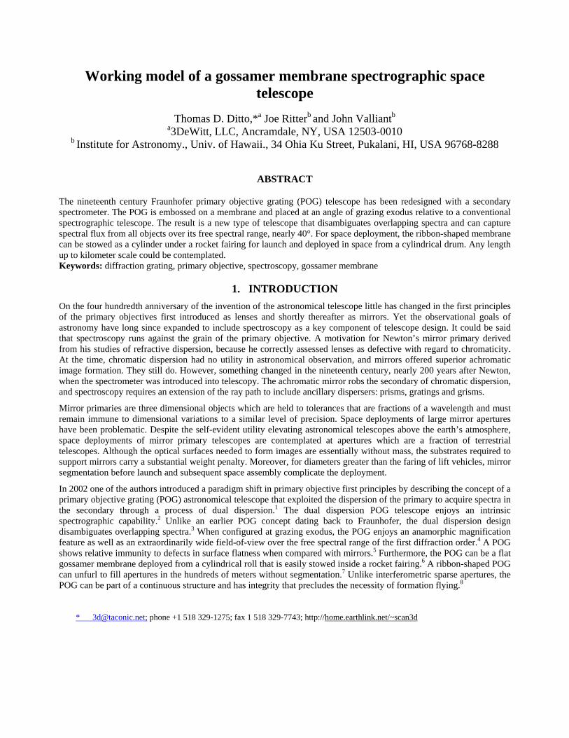
2. PRINCIPLE OF OPERATION Figure 1 is a diagram of the POG concept, illustrated with a transmission grating. The concept is the same for a reflection POG. For any object at an angle of incidence to the POG there is a corresponding wavelength detected after the secondary spectrometer. Acquisition of a line of right ascension is achieved by rotation of the assembly. On earth the rotation is accomplished though the rotation of the planet. In space the platform rotates. A star at a particular angle is
diffracted by POG A to secondary parabolic mirror B, and the light is focused on slit C. A secondary disperser, D separates out all the visible objects as spectrum E. Three distinct targets at angles -30°, -15°and 45° are illustrated in bold lines, but the entire line is covered. As the POG rotates and the stars precess, their entire spectra are taken over the course of an observation cycle. The image of the sky at E is the same image that would be produced by parabolic mirror B, but a very high resolution spectral spread is superimposed over the image. Data reduction correlates temporal data with angle of incidence. Any one object has its spectrum assembled from a series of snapshots, Figure 2.
Fig. 2 Three frames from a simulated observation cycle. The cross hairs track one object. The instantaneous amplitude
of all objects at unique wavelengths can be stored as a table for data reduction after the observation cycle.
Fig. 1 Dual dispersion POG astronomical telescope
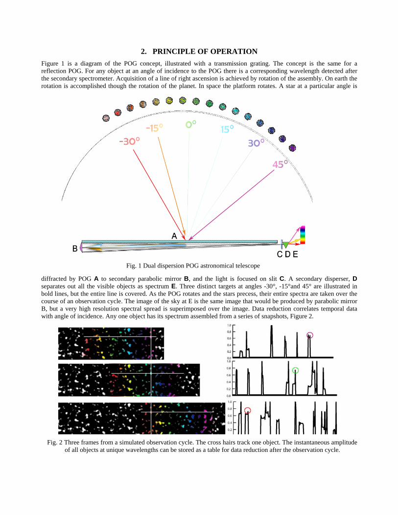
3. EMBODIMENT OF OPTICS AS A WORKING MODEL Newton could have demonstrated the dual dispersion principle upon which the POG telescope depends by extending his famous “Crucial Experiment” of 1668. Of course, dispersion would have been by prism, since the diffraction grating wasn’t reported in the literature until 1785 and was not ready for spectroscopy until well into the nineteenth century. Taking liberties with a page from Newton’s notebook, we show in Figure 3 how two sources focused onto a prism can pass through a hole in a mask to form two images in two colors at displacements proportional to the original sources.
Fig. 3 Il Experimentum Crucis Subjectum [The Counterfeit Crucial Experiment] with apologies to Isaac Newton
3.1 First Laboratory Demonstration
Magnification is only in one dimension where the HOE pitch variation results in formation of an image on focal plane FP corresponding to aperture a. However, the field-of-view for a lens of focal length FL is θ in both dimensions. Therefore if the diffraction higher-order is along one axis, the magnification feature is anamorphic, and the non-diffracting axis exhibits a field-of-view θ that is not magnified by the HOE.
The magnification feature is correlated to the angle of grazing incidence i. As i increases, the magnification geometrically increases to an asymptotic limit at i = 90° where magnification is putatively infinite. A plot of the relationship is shown in the log graph of Figure 2. The trade-off is that as the magnification grows, the efficiency e of the HOE decreases proportionately as per the correlated graph of Figure 3. Unlike refractive primary objectives, the field-of-view does not change as magnification increases. Instead, the image starts to disappear due to photon starvation.
Fig. 2 As magnification M increases asymptotically toward infinity, the efficiency e of the POG decreases toward zero
Geometric optics does not fully describe the magnification feature. Just as lenses have their diffraction limits, POG elements cannot resolve sub-wavelength details. The limitation is similar to lenses, that is, the wavelength of light cannot propagate without reinforcing itself at wavelength intervals. However, the anamorphic magnification feature exhibited by a POG is significantly greater than can be achieved with lenses, and wide fields-of-view in one dimension are independent of the magnification in the other dimension.
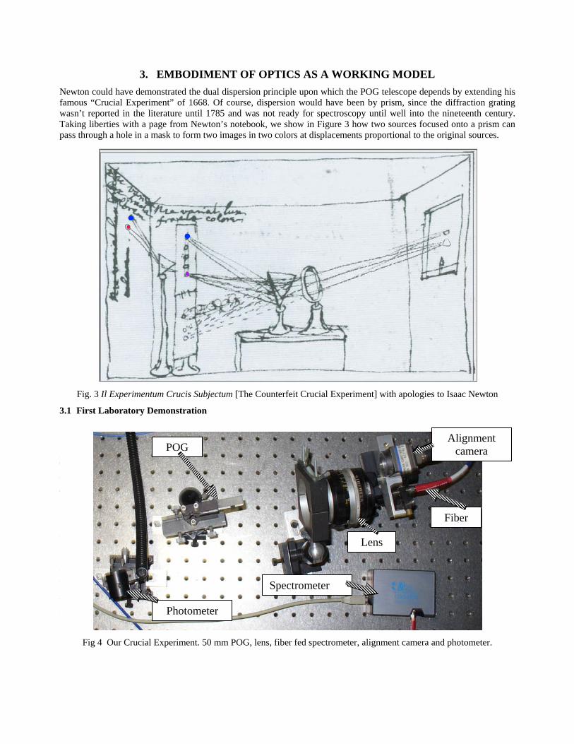
Fig 4 Our Crucial Experiment. 50 mm POG, lens, fiber fed spectrometer, alignment camera and photometer.
Photometer
Spectrometer
Alignment camera POG
Lens
Fiber
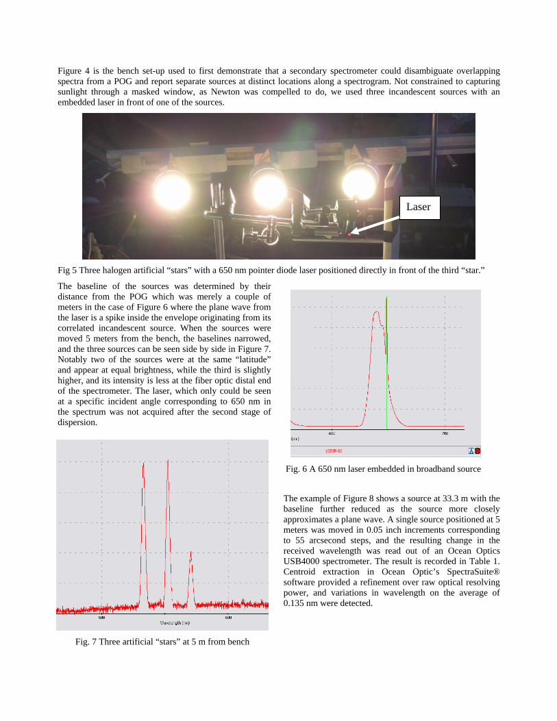
Figure 4 is the bench set-up used to first demonstrate that a secondary spectrometer could disambiguate overlapping spectra from a POG and report separate sources at distinct locations along a spectrogram. Not constrained to capturing sunlight through a masked window, as Newton was compelled to do, we used three incandescent sources with an embedded laser in front of one of the sources.
Fig 5 Three halogen artificial “stars” with a 650 nm pointer diode laser positioned directly in front of the third “star.”
The baseline of the sources was determined by their distance from the POG which was merely a couple of meters in the case of Figure 6 where the plane wave from the laser is a spike inside the envelope originating from its correlated incandescent source. When the sources were moved 5 meters from the bench, the baselines narrowed, and the three sources can be seen side by side in Figure 7. Notably two of the sources were at the same “latitude” and appear at equal brightness, while the third is slightly higher, and its intensity is less at the fiber optic distal end of the spectrometer. The laser, which only could be seen at a specific incident angle corresponding to 650 nm in the spectrum was not acquired after the second stage of dispersion.
The example of Figure 8 shows a source at 33.3 m with the baseline further reduced as the source more closely approximates a plane wave. A single source positioned at 5 meters was moved in 0.05 inch increments corresponding to 55 arcsecond steps, and the resulting change in the received wavelength was read out of an Ocean Optics USB4000 spectrometer. The result is recorded in Table 1. Centroid extraction in Ocean Optic’s SpectraSuite® software provided a refinement over raw optical resolving power, and variations in wavelength on the average of 0.135 nm were detected.
Laser
Fig. 6 A 650 nm laser embedded in broadband source
Fig. 7 Three artificial “stars” at 5 m from bench
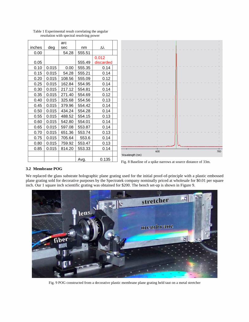
Table 1 Experimental result correlating the angular resolution with spectral resolving power
Fig. 8 Baseline of a spike narrows at source distance of 33m.
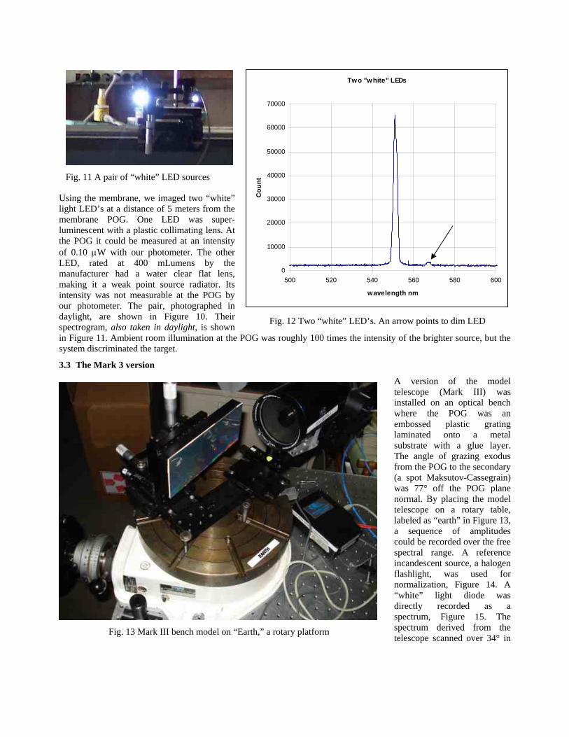
3.2 Membrane POG
We replaced the glass substrate holographic plane grating used for the initial proof-of-principle with a plastic embossed plane grating sold for decorative purposes by the Spectratek company nominally priced at wholesale for $0.01 per square inch. Our 1 square inch scientific grating was obtained for $200. The bench set-up is shown in Figure 9.
Fig. 9 POG constructed from a decorative plastic membrane plane grating held taut on a metal stretcher
inches deg arc sec nm Δλ
0.00 54.28 555.51
0.05 555.49 0.012 discarded
0.10 0.015 0.00 555.35 0.14 0.15 0.015 54.28 555.21 0.14 0.20 0.015 108.56 555.09 0.12 0.25 0.015 162.84 554.95 0.14 0.30 0.015 217.12 554.81 0.14 0.35 0.015 271.40 554.69 0.12 0.40 0.015 325.68 554.56 0.13 0.45 0.015 379.96 554.42 0.14 0.50 0.015 434.24 554.28 0.14 0.55 0.015 488.52 554.15 0.13 0.60 0.015 542.80 554.01 0.14 0.65 0.015 597.08 553.87 0.14 0.70 0.015 651.36 553.74 0.13 0.75 0.015 705.64 553.6 0.14 0.80 0.015 759.92 553.47 0.13 0.85 0.015 814.20 553.33 0.14
Avg. 0.135
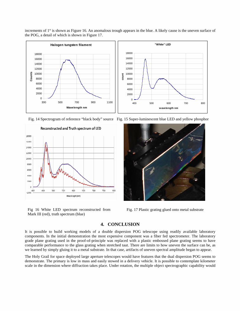
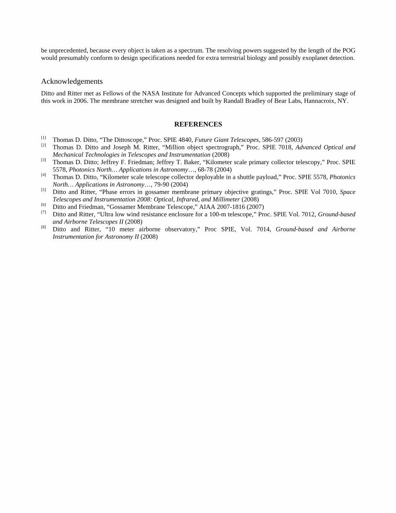
Using the membrane, we imaged two “white” light LED’s at a distance of 5 meters from the membrane POG. One LED was super-luminescent with a plastic collimating lens. At the POG it could be measured at an intensity of 0.10 μW with our photometer. The other LED, rated at 400 mLumens by the manufacturer had a water clear flat lens, making it a weak point source radiator. Its intensity was not measurable at the POG by our photometer. The pair, photographed in daylight, are shown in Figure 10. Their spectrogram, also taken in daylight, is shown in Figure 11. Ambient room illumination at the POG was roughly 100 times the intensity of the brighter source, but the system discriminated the target.
3.3 The Mark 3 version
A version of the model telescope (Mark III) was installed on an optical bench where the POG was an embossed plastic grating laminated onto a metal substrate with a glue layer. The angle of grazing exodus from the POG to the secondary (a spot Maksutov-Cassegrain) was 77° off the POG plane normal. By placing the model telescope on a rotary table, labeled as “earth” in Figure 13, a sequence of amplitudes could be recorded over the free spectral range. A reference incandescent source, a halogen flashlight, was used for normalization, Figure 14. A “white” light diode was directly recorded as a spectrum, Figure 15. The spectrum derived from the telescope scanned over 34° in
Fig. 13 Mark III bench model on “Earth,” a rotary platform
Fig. 11 A pair of “white” LED sources
Two "white" LEDs
0
10000
20000
30000
40000
50000
60000
70000
500 520 540 560 580 600
wavelength nm
Cou
nt
Fig. 12 Two “white” LED’s. An arrow points to dim LED
increments of 1° is shown as Figure 16. An anomalous trough appears in the blue. A likely cause is the uneven surface of the POG, a detail of which is shown in Figure 17.
Halogen tungsten filament
0
2000
4000
6000
8000
10000
12000
14000
16000
18000
300 500 700 900 1100
Wavelength nm
Cou
nts
"White" LED
0
2000
4000
6000
8000
10000
12000
14000
16000
18000
400 500 600 700 800
wavelength nm
coun
t
Fig. 14 Spectrogram of reference “black body” source Fig. 15 Super-luminescent blue LED and yellow phosphor
4. CONCLUSION It is possible to build working models of a double dispersion POG telescope using readily available laboratory components. In the initial demonstration the most expensive component was a fiber fed spectrometer. The laboratory grade plane grating used in the proof-of-principle was replaced with a plastic embossed plane grating seems to have comparable performance to the glass grating when stretched taut. There are limits to how uneven the surface can be, as we learned by simply gluing it to a metal substrate. In that case, artifacts of uneven spectral amplitude began to appear.
The Holy Grail for space deployed large aperture telescopes would have features that the dual dispersion POG seems to demonstrate. The primary is low in mass and easily stowed in a delivery vehicle. It is possible to contemplate kilometer scale in the dimension where diffraction takes place. Under rotation, the multiple object spectrographic capability would
Fig 16 White LED spectrum reconstructed from Mark III (red), truth spectrum (blue)
Fig. 17 Plastic grating glued onto metal substrate
be unprecedented, because every object is taken as a spectrum. The resolving powers suggested by the length of the POG would presumably conform to design specifications needed for extra terrestrial biology and possibly exoplanet detection.
Acknowledgements Ditto and Ritter met as Fellows of the NASA Institute for Advanced Concepts which supported the preliminary stage of this work in 2006. The membrane stretcher was designed and built by Randall Bradley of Bear Labs, Hannacroix, NY.
REFERENCES
[1] Thomas D. Ditto, “The Dittoscope,” Proc. SPIE 4840, Future Giant Telescopes, 586-597 (2003) [2] Thomas D. Ditto and Joseph M. Ritter, “Million object spectrograph,” Proc. SPIE 7018, Advanced Optical and
Mechanical Technologies in Telescopes and Instrumentation (2008) [3] Thomas D. Ditto; Jeffrey F. Friedman; Jeffrey T. Baker, “Kilometer scale primary collector telescopy,” Proc. SPIE
5578, Photonics North… Applications in Astronomy…, 68-78 (2004) [4] Thomas D. Ditto, “Kilometer scale telescope collector deployable in a shuttle payload,” Proc. SPIE 5578, Photonics
North… Applications in Astronomy…, 79-90 (2004) [5] Ditto and Ritter, “Phase errors in gossamer membrane primary objective gratings,” Proc. SPIE Vol 7010, Space
Telescopes and Instrumentation 2008: Optical, Infrared, and Millimeter (2008) [6] Ditto and Friedman, “Gossamer Membrane Telescope,” AIAA 2007-1816 (2007) [7] Ditto and Ritter, “Ultra low wind resistance enclosure for a 100-m telescope,” Proc. SPIE Vol. 7012, Ground-based
and Airborne Telescopes II (2008) [8] Ditto and Ritter, “10 meter airborne observatory,” Proc SPIE, Vol. 7014, Ground-based and Airborne
Instrumentation for Astronomy II (2008)