wiriticity
TRANSCRIPT


The idea of transmitting power through the air has been around for over a century, with Nikola Tesla’s ideas and experiments which dates back to 1891.
Most approaches to wireless power transfer is , use an
electromagnetic (EM) field of some frequency as the means
by which the energy is sent. But objects that get
between the transmitter and receiver can block the beam,
interrupting the power transmission.
At microwave frequencies, a similar approach can be used
to efficiently transmit power over large distances using the
radiated EM field from appropriate antennas . However,
system complexity apply for these radiative approaches.
Operation of a transformer can be considered a form of wireless power transfer since it uses the principle of magnetic induction to transfer energy from a primary coil to a secondary coil without a direct electrical connection. However, for these systems to operate efficiently, the primary coil (source) and secondary coil (device) must be located in close proximity and carefully positioned with respect to one another.
LCD TV 250W supplied wirelessly

But what about going over somewhat larger distances or having more freedom in positioning the source and device relative to each other?
Yes, High quality factor resonators enable efficient energy transfer at lower coupling rates, i.e., at greater distances , with more positional freedom . Therefore, this approach is sometimes referred to as “highly resonant” wireless energy transfer or “highly resonant” wireless power transfer(HR-WPT).
MIT team was first to demonstrate the highly resonant technique using a magnetic field to transfer energy over a mid-range distance of 2 meters, and an industry was born.

Block diagram of wireless energy transfer :
• Progressing from left to right on the top , the input power to the system is usually wall power (AC mains) which is converted to DC in an AC/DC rectifier block.
• A high efficiency switching amplifier converts the DC voltage into an RF (radio frequency) voltage waveform used to drive the source resonator.
• Often an impedance matching network (IMN) is used to efficiently couple theamplifier output to the source resonator while enabling efficient switching-amplifier operation.
•The magnetic field generated by the source resonator couples tothe device resonator, exciting the resonator and causing energy to build up in it.
• This energy is coupled out of the device resonator to do useful work, for example, directly powering a load or charging a battery etc
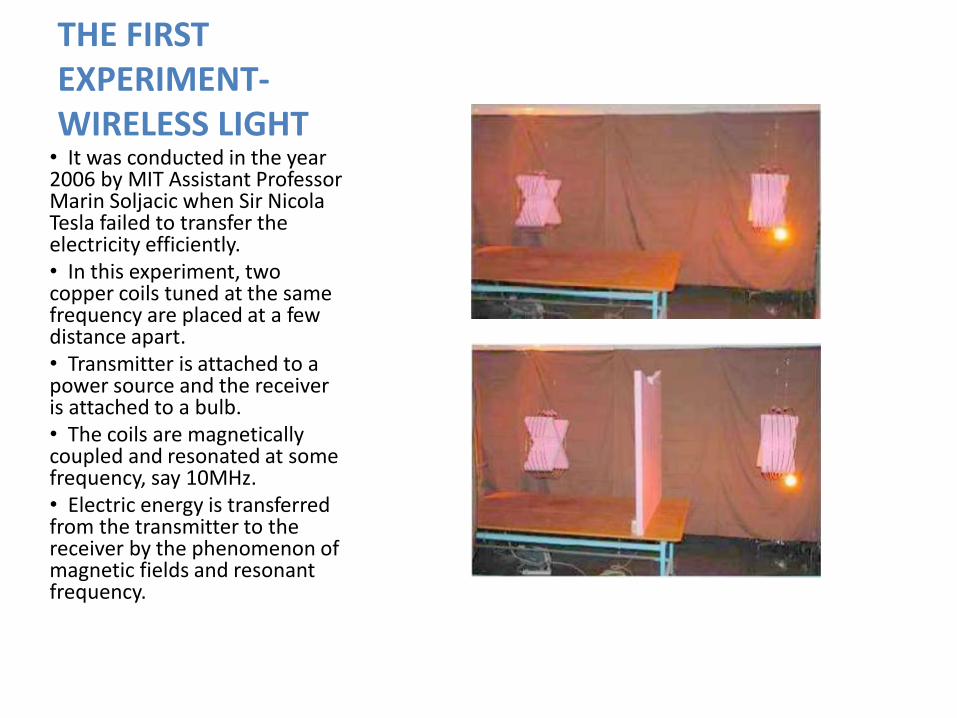
THE FIRST EXPERIMENT-WIRELESS LIGHT• It was conducted in the year 2006 by MIT Assistant Professor Marin Soljacic when Sir Nicola Tesla failed to transfer the electricity efficiently.• In this experiment, two copper coils tuned at the same frequency are placed at a few distance apart.• Transmitter is attached to a power source and the receiver is attached to a bulb.• The coils are magnetically coupled and resonated at some frequency, say 10MHz.• Electric energy is transferred from the transmitter to the receiver by the phenomenon of magnetic fields and resonant frequency.

THE FIRST EXPERIMENT-WIRELESS LIGHT•The blue lines represent the magnetic field induced near the power source.
•The yellow lines represent the flow of energy from the power source to the light bulb.
•If a conductive obstacle is placed in between the source and the capturing device, the magnetic fields wrap around the obstacle and pass to the witricity capture coil.

High efficiency( 40-45 % efficiency).
Witricity sources transfer energy only when it is needed.
Energy transfer via magnetic near fields can penetrate and wrap around obstacles.
It is a non- radiative mode of energy and relies on magnetic near field.
Magnetic fields interact very weakly with biological organisms and hence are considered to be safe.
Cost efficient
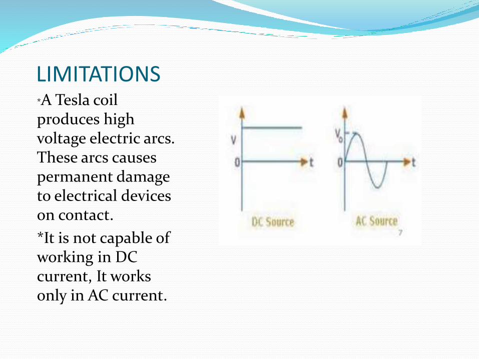
LIMITATIONS*A Tesla coil produces high voltage electric arcs. These arcs causes permanent damage to electrical devices on contact.
*It is not capable of working in DC current, It works only in AC current.

APPLICATIONS•It can be used to provide:
• DIRECT WIRELESS POWER:• when all the power a device needs is provided wirelessly and no batteries are required. This mode is for a device that is always used within range of its witricity power source.
AUTOMATIC WIRELESS CHARGING: when a device with rechargeable batteries charges itself while still in use or at rest, without requiring a power cord or battery replacement. This mode is for a mobile device that is used both in and out of range of its witricity power source.

We have understood the
future anticipations in the
field of wireless energy
transfer .With the advent
of portable electronics that
seem to need constant
charging ,researchers are
exploring methods to
wireless electricity
practical.

Nicola Tesla, “The transmission of electrical energy without wires”, Electrical World and Engineer, March 1905. http://www.tfcbooks.com/tesla/1904-03-05.htm, (acc. Dec. 08).
William C. Brown, “The history of power transmission by radio waves”, Microwave
Theory and Techniques, IEEE Transactions, 32(9):1230-1242, September 1984.
A.B. Kurs, A. Karalis, R. Moffatt, J.D. Joannopoulos, P.H. Fisher, and M. Soljacic, “Wireless Power Transfer via Strongly Coupled Magnetic Resonances”, Science, 317, pp. 83-86, (2007).
A. Karalis, J.D. Joannopoulos, and M. Soljacic, “Efficient Wireless Non-radiative Midrange Energy Transfer”.
