wireless firing interface for power electronic...
TRANSCRIPT

ECE 4600 Project Proposal
Group 12
Wireless Firing Interface for Power Electronic Converters
Authors: Supervisors:
Brennan Martin Dr. Ani Gole
Luchen Song Cyrus Shafai
Jason Gole
Meng Wang
Date of Submission:
Sept 27, 2013

ii
Contents
1. Introduction………………………………………………………………………………………...1
2. Project Specifications………………………………………………………………………………2
2.1 Wireless Specifications……………………………………………………………………......2
2.2 Control Board Specifications….………………………………………………………………4
2.3 Converter Specifications………………………………………………………………………5
3. Milestones………………………………………………………………………………………….6
4. Gantt Chart…………………………………………………………………………………………7
5. Budget……………………………………………………………………………………………...8
6. References………………………………………………………………………………………….9
List of Tables
Table 1-Wireless specifications
Table 2-Controller specifications
Table 3-Converter specifications
Table 4-Milestones/task distribution
Table 5-Proposed budget
List of Figures
Figure 1: Proposed system topology
Figure 2: ZigBee wireless network
Figure 3: Chopper circuit with DC motor load
1
1. Introduction
Power Electronic (PE) converters are a family of devices used to convert electricity from one
form to another. Encompassing a variety of DC-DC, DC-AC, and AC-AC devices, all modern PE
converters rely on the rapid switching of semiconductor devices to function. However, PE converters are
not capable of generating their own control signals, necessitating the installation of either a hardwired
control board, or a wired control system capable of transmitting them. However, both methods pose
problems. Hardwired boards are small, cost effective and easily installed, but can only give a single
output. Changing the output of the system would require a new board. On the other hand, wired systems
give operators control and allow easy monitoring, but are expensive, and also require fiber-optic cables if
the system is to remain electrically isolated. A wireless system would simultaneously be small,
controllable, and electrically isolated.
The goal of this project is to design and implement a wireless system that is capable of
controlling a basic DC-DC PE converter. The system will accept user input on a PC based interface,
transmit data to a control board connected to the converter, and allow a variety of DC outputs from the
converter. To allow wireless control of the system, we will be utilizing the ZigBee wireless protocol.
ZigBee offers a simple, reliable transmission protocol which is designed for low power usage, whilst
giving access to a multitude of integrated transmitter/microcontroller (µC) units.
2
2. Project Specifications
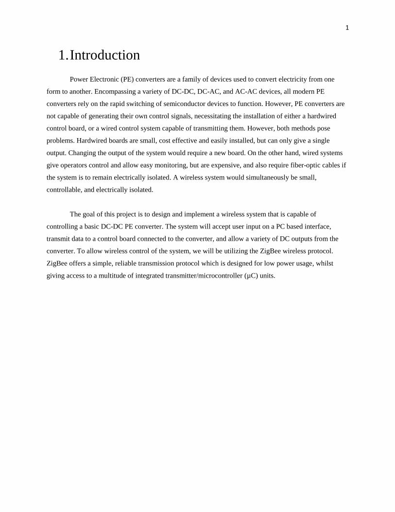
The project will be broken down into 4 primary components:
A PC based user interface
A Wireless ZigBee based transmitter/receiver system
An IGBT (Insulated Gate Bipolar Transistor) driver board
A DC-DC PE converter
Figure 1: Proposed system topology
Figure 1 gives an overview of the entire system. The user interface on a pc will allow the user to
make changes to input control signals for the converter. The signal is then sent to out of the transmitter
and picked up by the receiver. The receiver sends the signal to the IGBT driver, which controls the
converter using the acquired signal. The output of the converter can then be used to power a load.
2.1 Wireless Specifications
We will be using the ZigBee wireless protocol to send data from the user to the IGBT driver.
ZigBee operates according to IEEE standard 802.15.4. The ZigBee protocol will allow us a wireless range
of 10 to 100 meters [1]. Testing will need to be done to determine the exact range.
3
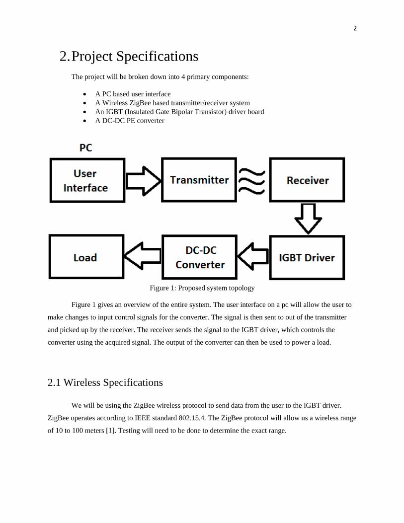
ZigBee allows one coordinator to send data out to one or more routers or end devices, as can be
seen in Figure 2. The routers can then send data further to more routers or end devices. The use of
multiple routers allows the signal to be relayed from one coordinator to several routers before reaching
the desired end device, increasing the maximum range of the system. For the purposes of this project,
only one coordinator and one end device will be used, with no intermediate routers.
Figure 2: ZigBee wireless network [2]
To communicate between the user and the IGBT driver, both a transmitter and a receiver are
needed. The transmitter will be the coordinator node, while the receiver will be the only end device. The
ZigBee module used will contain a built in antennae, as well as a microcontroller. Having built in
components will reduce the complexity of the design and will allow us to use two identical ZigBee
modules for both transmitter and receiver.
Using the ZigBee protocol for our wireless communication will allow us to use a single 9 volt
battery to power the microcontrollers. The use of a single battery is possible because the ZigBee wireless
protocol uses very little power, especially when compared to other wireless standards such as Wi-Fi or
Bluetooth. Other wireless standards have the advantage of transmitting data faster than ZigBee, but for
the purposes of this project low power consumption is more important than speed of transmission.

4
The user interface will allow the duty cycle of the transmitted signal to be modified. The
microprocessor within the receiver will send the signal to the IGBT driver with a frequency of 2 to 5
kilohertz. The exact value will be determined when tests concerning the losses and smoothness of the
waveform have been conducted.
Table 1-Wireless specifications
Description Specification
Wireless standard ZigBee (IEEE standard 802.15.4)
Power Source 9 V
Wireless range 10-100m
Number of microcontrollers 2
Switching frequency 2-5 KHz
2.2 Control Board Specifications
As a microcontroller cannot safely supply a sufficient amount of power to switch on an IGBT, we
require a controller board to interpose between the microcontroller and the converter. The controller
board must accept an input signal that can be safely generated by a low power microcontroller, output
enough current and voltage to switch an IGBT, and accept a supply voltage that can be provided by a
battery. Desirable but nonessential characteristics include low delay time, low power usage, and the
presence of a low power or standby mode.
Table 2-Control Board Specifications
Description Specification
Supply Voltage 6-12 V
Input Voltage 2-5 V
Input Current .1-.5 mA
Output Current .25-1 A
Delay Time 5 µS
5
2.3 Converter Specifications
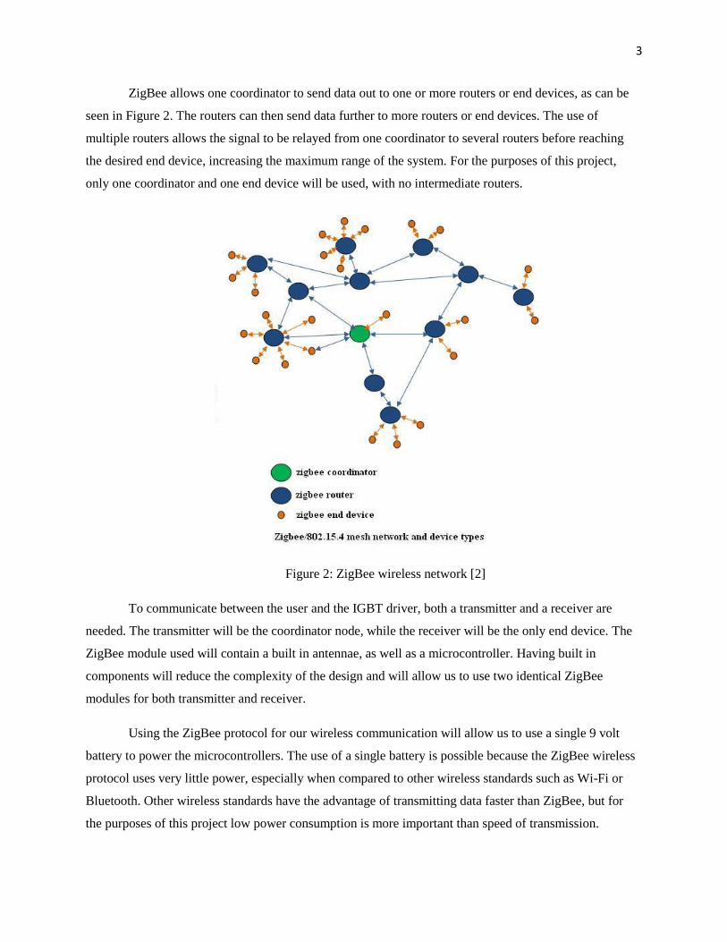
The DC-DC converter we are planning to use is called a chopper. The chopper is controlled by an
IGBT power electronic switch. The IGBT is repeatedly switched on and off by a voltage pulse. The
on time per voltage cycle can be controlled by controlling the on/off time ratio of IGBT, called the
duty cycle. If the on time is D, and the IGBT is switched on/off during period T, then the off time is
(1-D)*T. The average voltage output [3] is then:
[
]
For the purposes of this project, we want to select a voltage that is high enough to be stepped
down to a useful level, but still low enough that we do not need to use high voltage equipment. We
also want enough power output to do useful work with the output, such as driving a DC motor.
Table 3-Converter specifications
Description Specification
Input voltage 28 V
Output voltage 12 – 24 V
Output current 5 A
Switching frequency 2 -5 kHz
Figure 3: Chopper circuit with DC motor load [4]

6
3. Milestones
Table 3 contains a list of project milestones and tasks, as well as the group members in charge of
completing them. A number of administrative tasks are absent from this list, but are listed in the
Gantt chart.
Table 4-Milestones/task distribution
Milestones and Tasks Individuals in charge
Research ZigBee communications Jason & Luchen
Coding language for µCs Jason & Luchen
DC-DC converter Meng
Design Design receiver PCB Jason
Design transmitter PCB Luchen
Code implementation Jason & Luchen
DC-DC converter Meng
IGBT driver Meng & Brennan
Simulation Test receiver design Jason
Test transmitter design Luchen
DC-DC converter Meng
Build Build receiver PCB Jason
Build transmitter PCB Luchen
Code µCs Jason & Luchen
Connect µC to IGBT driver Brennan
Connect µC to ZigBee transmitter Brennan
DC-DC converter circuit Meng & Brennan
Testing Wireless communication Jason & Luchen
DC-DC converter circuit Meng & Brennan
Implementation and final test Converter control with ZigBee Group

7
4. Gantt Chart

8
5. Budget
Table 4 contains a list of required components for our design, as well as associated costs. The
costs of shipping and taxes are included in the cost of each component. Our final cost is well
below the $400 maximum cost of the project. This gives us $150 to be used for unforeseen costs,
such as burnt out parts.
Table 5-Proposed Budget
Required part Number of parts Cost of parts
ZigBee module 2 $80.00
9 volt battery 2 $15.00
PCB 2 $100.00
Passive components TBD $25.00
IGBT 2 $10.00
IGBT driver 1 $5.00
MISC components TBD $15.00
Total $250.00

9
6. References
[1] ZigBee Alliance (2013) Specification FAQ [Online] Available: http://www.zigbee.org [Sep. 26, 2013]
[2]RF Wireless World (2013) ZigBee Tutorial [Online] Available: http://www.rfwireless-
world.com/Tutorials/Zigbee_tutorial.html [Sep. 26, 2013]
[3]Mohan, Undeland, Riobbins, Power Electronics, 3rd
Edition. Hoboken: Wiley, 2002.
[4] Pedro Daniel Dinis Teodoro, “Development of a simulation environment of an entertainment
humanoid robot”, MS Thesis, Dept. Mech. Eng., Instituto Superior Technico, Lisbon, Portugal, 2007.