wind and snow loads lws+ · for flat roofs with a parapet, the wind load on the parapet is...
TRANSCRIPT
Wind and Snow Loads LWS+
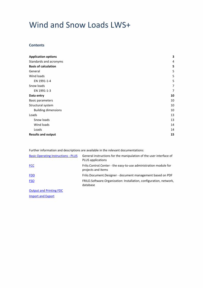
Contents
Application options 3 Standards and acronyms 4 Basis of calculation 5 General 5 Wind loads 5
EN 1991-1-4 5 Snow loads 7
EN 1991-1-3 7 Data entry 10 Basic parameters 10 Structural system 10
Building dimensions 10 Loads 13
Snow loads 13 Wind loads 14 Loads 14
Results and output 15
Further information and descriptions are available in the relevant documentations:
Basic Operating Instructions - PLUS General instructions for the manipulation of the user interface of PLUS applications
FCC Frilo.Control.Center - the easy-to-use administration module for projects and items
FDD Frilo.Document.Designer - document management based on PDF
FSO FRILO.Software.Organization: Installation, configuration, network, database
Output and Printing FDC
Import and Export
LWS+
FRILO Software GmbH Page 3
Application options
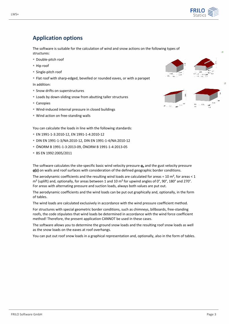
The software is suitable for the calculation of wind and snow actions on the following types of structures:
Double-pitch roof
Hip roof
Single-pitch roof
Flat roof with sharp-edged, bevelled or rounded eaves, or with a parapet
In addition:
Snow drifts on superstructures
Loads by down-sliding snow from abutting taller structures
Canopies
Wind-induced internal pressure in closed buildings
Wind action on free-standing walls
You can calculate the loads in line with the following standards:
EN 1991-1-3:2010-12, EN 1991-1-4:2010-12
DIN EN 1991-1-3/NA:2010-12, DIN EN 1991-1-4/NA:2010-12
ÖNORM B 1991-1-3:2013-09, ÖNORM B 1991-1-4:2013-05
BS EN 1992:2005/2011
The software calculates the site-specific basic wind velocity pressure qb and the gust velocity pressure q(z) on walls and roof surfaces with consideration of the defined geographic border conditions.
The aerodynamic coefficients and the resulting wind loads are calculated for areas = 10 m², for areas < 1 m² (uplift) and, optionally, for areas between 1 and 10 m² for upwind angles of 0°, 90°, 180° and 270°. For areas with alternating pressure and suction loads, always both values are put out.
The aerodynamic coefficients and the wind loads can be put out graphically and, optionally, in the form of tables.
The wind loads are calculated exclusively in accordance with the wind pressure coefficient method.
For structures with special geometric border conditions, such as chimneys, billboards, free-standing roofs, the code stipulates that wind loads be determined in accordance with the wind force coefficient method! Therefore, the present application CANNOT be used in these cases.
The software allows you to determine the ground snow loads and the resulting roof snow loads as well as the snow loads on the eaves at roof overhangs.
You can put out roof snow loads in a graphical representation and, optionally, also in the form of tables.

Wind and Snow Loads
Page 4 Software for structural calculation and design
Standards and acronyms EN 1991 1-3 / EN 1991-1-4
If the National Annexes are not mentioned explicitly, the statements apply to all National Annexes in the same way.
NDP
Nationally defined parameter; parameter defined in the National Annex (NA).
Implemented National Annexes and Acronyms used
EN 1991-1-3: EN 1991-1-3:2010-12
EN 1991-1-4 EN 1991-1-4:2010-12
Implemented National Annexes (NA):
See overview of the implemented National Annexes at www.frilo.eu
LWS+
FRILO Software GmbH Page 5
Basis of calculation
General The software first calculates the basic wind velocity pressures for the different directions of approach as well as the ground snow load based on the specified geographic border conditions.
After the definition of the system parameters, the aerodynamic coefficients with the associated wind loads and/or roof snow loads are calculated.
For the special types ‘wind-induced internal pressure’ and ‘wind on free-standing walls’, only the wind loads and for ‘snow drifts’ and ‘roofs abutting taller structures’, only the snow loads are calculated.
Reference examples for the LWS+ application are available on our home page, under ServiceArticles/ InformationReference Examples.
Example 1 (in German): Hip roof as per DIN EN 1991
Example 2 (in German): Snow at roofs abutting taller structures as per DIN EN 1991:
Wind loads The software first determines the basic wind velocity pressure qb. Depending on the selected standard, the value must either be specified manually by the user or is proposed automatically based on the geographic border conditions.
By taking various coefficients and factors into account, the height-specific gust velocity pressure qp(z) can be calculated.
As shown in illustration 7.5, the gust velocity pressure qp(z) on all roof surfaces and walls is always calculated for the reference height z = ridge height.
The software allows a height-specific distribution of the gust velocity pressure over vertical walls in accordance with illustration 7.4 .
The external and internal pressures are calculated with the help of the aerodynamic coefficients for the different types of buildings.
Wind action on free-standing walls is calculated with the help of aerodynamic coefficients in accordance with paragraph 7.4.
For flat roofs with a parapet, the wind load on the parapet is calculated as for free-standing walls in accordance with paragraph 7.4.
EN 1991-1-4 Eurocode proposes the following equation for the calculation of the basic wind velocity pressure qb:
2b b
1q v
2= ◊r◊
(4.10)
with b dir season b,0v c c v= ◊ ◊ (4.1)
The directional and the seasonal factor can be set to 1 for reasons of simplification whereas the basic value of the basic wind velocity vb,0 is imposed by the competent authority or the relevant National Annex.
The gust velocity pressure for the height z can be calculated from qb with the help of the terrain factor as per (4.8) and (4.9):
p e bq (z) c (z) q= ◊ As shown in illustration 7.5, the gust velocity pressure qp(z) on all roof surfaces and walls is always calculated for the reference height z = ridge height.
Wind and Snow Loads
Page 6 Software for structural calculation and design
The terrain factor ce is determined with the help of various coefficients in the expression:
[ ] 2 2e v r oc (z) 1 7 I (z) c (z) c (z)= + ◊ ◊ ◊ .
with turbulence intensity
Iv
o0
kI (z) z
c (z) lnz
=◊
(4.7)
The turbulence factor kI and the topographic factor co may be assumed 1.0 for simplification. Methods for the accurate calculation are proposed in the annex to EN.
The friction coefficient can be determined as follows:
r r0
zc (z) k ln
z= ◊
(4.4) with
0,070
r0,II
zk 0,19
zÊ ˆ
= ◊Á ˜Ë ¯
The aerodynamic coefficients are specified for the different building shapes in paragraph 7.2. The wind loads are calculated using these factors:
Exterior: e p pew q (z) c= ◊
Interior: i p piw q (z) c= ◊
Wind action on canopies is not treated in the Eurocode (without NA).
The National Annexes may specify other methods and values!
In the text below, only the differences between the National Annexes are described:
DIN EN 1991
Equation 4.8 cannot be used for Germany because of the wind profile for this region. The gust velocity pressure is calculated as specified in annex NA.B instead.
In Germany, wind zones are distinguished in addition to terrain categories.
The tables NA.B.2 and NA.B.4 propose formulae for the determination of qp and vp for different terrain categories and wind zones.
In Germany, the aerodynamic coefficients stipulated by the Eurocode (without NA) are used in most cases. There are some tables for vertical walls and a supplement for flat roofs, however.
Wind action on canopies is calculated using the aerodynamic coefficients specified in annex NA.V.
ÖNORM EN 1991
Equation 4.8 cannot be used for Austria due to the applicable wind profile for this region. The stipulations for the calculation of the gust velocity pressure specified in annex NA.6.3.2.1 is used instead.
In paragraph 6.3.2.1, table 1 gives different expressions for the determination of qp depending on the terrain category. In Austria, the categories 0 and I need not be taken into consideration.
Paragraph 9.2 contains standard-specific tables for wind pressure coefficients for wind action on the different types of buildings.
Wind action on canopies is calculated using the aerodynamic coefficients specified in paragraph 9.2.9.
LWS+
FRILO Software GmbH Page 7
Snow loads The software first determines the ground snow load sk based on the specified border conditions.
Subsequently, the roof snow load si can be calculated by taking various factors and the shape coefficients for the different types of buildings into account.
Depending on the selected type, the snow drift load and the snow load on the eaves are determined in addition with the help of shape coefficients.
You can optionally put out accidental snow loads for a given factor Cesl.
Another option allows you to put out the snow drift load cases for saddle-type roofs (case II and III).
If projections have been defined, the loads caused by overhanging snow at the eaves are determined. Because high roof snow loads in exposed locations may produce unrealistically high snow loads on the eaves, State Building Codes often provide factors to reduce the loads by overhanging snow.
Optionally, you can define snow guards and calculate the snow loads on these guards.
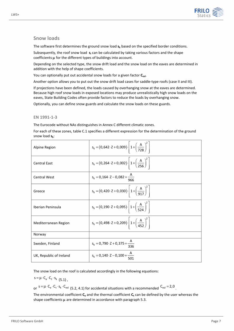
EN 1991-1-3 The Eurocode without NAs distinguishes in Annex C different climatic zones.
For each of these zones, table C.1 specifies a different expression for the determination of the ground snow load sk:
Alpine Region ( )2
kA
s 0,642 Z 0,009 1728
È ˘Ê ˆ= ◊ + ◊ +Í ˙Á ˜Ë ¯Í ˙Î ˚
Central East ( )2
kA
s 0,264 Z 0,002 1256
È ˘Ê ˆ= ◊ + ◊ +Í ˙Á ˜Ë ¯Í ˙Î ˚
Central West kA
s 0,164 Z 0,082966
= ◊ - +
Greece ( )2
kA
s 0,420 Z 0,030 1917
È ˘Ê ˆ= ◊ + ◊ +Í ˙Á ˜Ë ¯Í ˙Î ˚
Iberian Peninsula ( )2
kA
s 0,190 Z 0,095 1524
È ˘Ê ˆ= ◊ + ◊ +Í ˙Á ˜Ë ¯Í ˙Î ˚
Mediterranean Region ( )2
kA
s 0,498 Z 0,209 1452
È ˘Ê ˆ= ◊ + ◊ +Í ˙Á ˜Ë ¯Í ˙Î ˚ Norway
Sweden, Finland kA
s 0,790 Z 0,375336
= ◊ + +
UK, Republic of Ireland kA
s 0,140 Z 0,100501
= ◊ - +
The snow load on the roof is calculated accordingly in the following equations:
e t ks C C s= m◊ ◊ ◊ (5.1) ,
or e t k esls C C s C= m◊ ◊ ◊ ◊ (5.2, 4.1) for accidental situations with a recommended eslC 2,0= .
The environmental coefficient Ce and the thermal coefficient Ct can be defined by the user whereas the shape coefficients are determined in accordance with paragraph 5.3.
Wind and Snow Loads
Page 8 Software for structural calculation and design
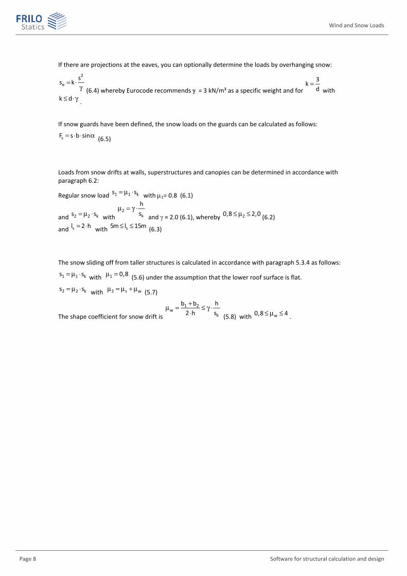
If there are projections at the eaves, you can optionally determine the loads by overhanging snow: 2
es
s k= ◊g (6.4) whereby Eurocode recommends = 3 kN/m³ as a specific weight and for
3k
d=
with k d£ ◊ g .
If snow guards have been defined, the snow loads on the guards can be calculated as follows:
sF s b sin= ◊ ◊ a (6.5)
Loads from snow drifts at walls, superstructures and canopies can be determined in accordance with paragraph 6.2:
Regular snow load 1 1 ks s= m ◊ with 1= 0.8 (6.1)
and 2 2 ks s= m ◊ with 2
k
hs
m = g ◊ and = 2.0 (6.1), whereby 20,8 2,0£ m £ (6.2)
and sl 2 h= ◊ with s5m l 15m£ £ (6.3)
The snow sliding off from taller structures is calculated in accordance with paragraph 5.3.4 as follows:
1 1 ks s= m ◊ with 1 0,8m = (5.6) under the assumption that the lower roof surface is flat.
2 2 ks s= m ◊ with 2 s wm = m +m (5.7)
The shape coefficient for snow drift is
1 2w
k
b b h2 h s+m = £ g ◊◊ (5.8) with w0,8 4£ m £ .

LWS+
FRILO Software GmbH Page 9
It is permissible to set the shape coefficient for sliding-off snow s to 0 if a ≤ 15°. Otherwise, the value is assumed 50 % of the roof snow load of the abutting roof surface.
( )( )
Ï a £ ∞Ôm = Ì◊m a > ∞ÔÓ
sDachfläche
0 15
0,5 15
The length of the snow drift is sl 2 h= ◊ with s5m l 15m£ £ (6.3)
The National Annexes may specify other methods and values!
In the text below, only the differences among the National Annexes are described:
DIN EN 1991
The snow and climatic zones specified in Annex C are not relevant for Germany. The German NA specifies its own snow zones as shown on the map NA.1 and associated formulae for the calculation of the ground snow load sk such as the equations specified by NA.1 to NA.3 including specific basic amounts.
The shape coefficients are taken over for the most part, except for the coefficients for adjacent roofs and roofs abutting taller structures, which are stipulated in the NCI to 5.3.4(4) and 5.3.6.
It is permissible to determine w in accordance with (NA.4). The expressions (NA.5) to (NA.8) stipulate
deviating limits for w sm +m .
For snow loads on the eaves, the German NA recommends setting the k coefficient to 0.4.
For the accidental situation, a factor Cesl = 2.3 should be assumed.
ÖNORM EN 1991
The snow zones and climatic zones specified in Annex C are not relevant for Austria. The Austrian NA specifies its own snow zones in NA Annex A and associated formulae for the calculation of the ground snow load sk in NA Annex B.
The shape coefficients are taken over for the most part. Specific values are defined in 4.5.2 for 2 and barrel roofs.
4.5.2.3 specifies deviating limits for w.
For snow loads on the eaves, the NA gives a separate formula in 4.6.2.

Wind and Snow Loads
Page 10 Software for structural calculation and design
Data entry
Basic parameters To define the basic parameters, first select the load standard. The available standards depend on your licences.
Depending on the selected standard, a list may be displayed for the selection of a municipality. The selection of the municipality provides for the pre-setting of specific parameters, such as the wind or snow zone, for example. If you change these values manually, the selection of the municipality is disregarded.
Moreover, the ground level above MSL is adjusted automatically.
Structural system Type select the type of roof.
Symmetrical if this option is enabled, the symmetrical values are set automatically and are greyed out in the user interface.
Building dimensions First, the values for a double-pitch roof are described. Values for other roof types are described subsequently.
Double-pitch/ single-pitch roof h building height up to the ridge
l building length (in ridge direction, from gable to gable)
ble building width on the left side of the ridge (projection length)
bri building width on the right side of the ridge (projection length)
le roof pitch on the left
ri roof pitch on the right
ole roof overhang on the left
ori roof overhang on the right
o1 roof overhang at the front gable
o2 roof overhang at the rear gable
ble distance of the left snow guard to the ridge (if applicable)
bri distance of the right snow guard to the ridge (if applicable)
With wind-induced internal pressure see the type wind-induced internal pressure
LWS+
FRILO Software GmbH Page 11
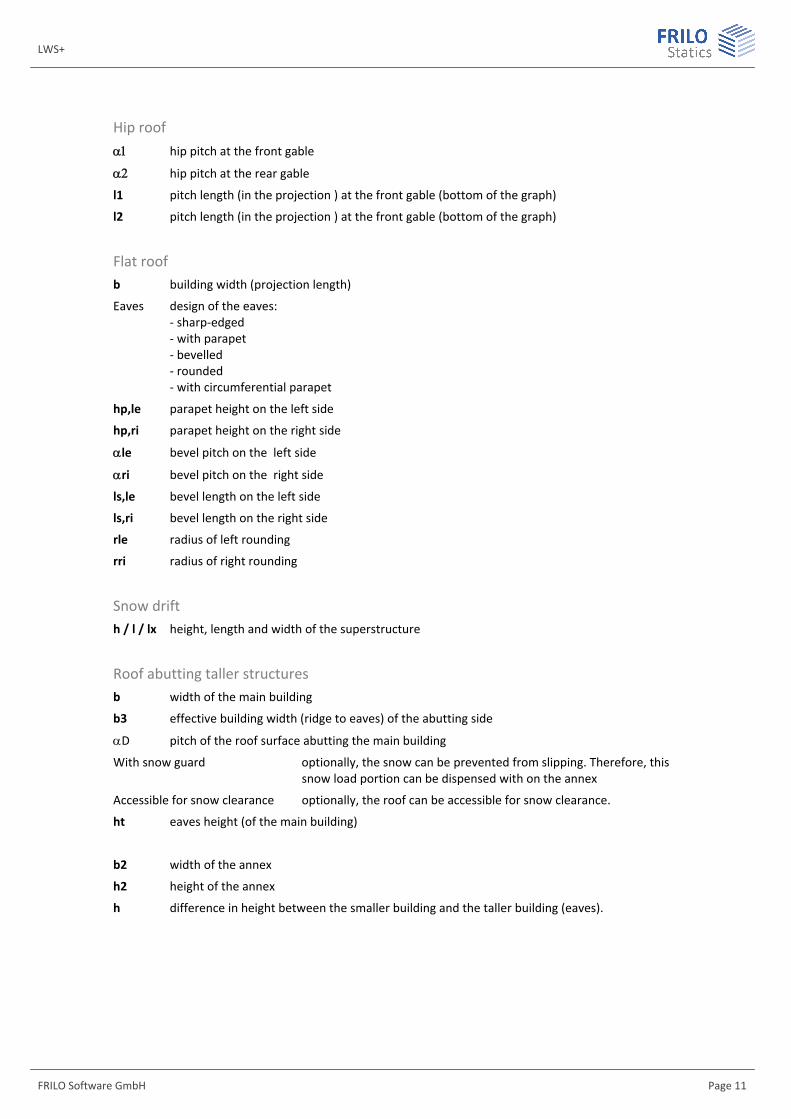
Hip roof hip pitch at the front gable
hip pitch at the rear gable
l1 pitch length (in the projection ) at the front gable (bottom of the graph)
l2 pitch length (in the projection ) at the front gable (bottom of the graph)
Flat roof b building width (projection length)
Eaves design of the eaves: - sharp-edged - with parapet - bevelled - rounded - with circumferential parapet
hp,le parapet height on the left side
hp,ri parapet height on the right side
le bevel pitch on the left side
ri bevel pitch on the right side
ls,le bevel length on the left side
ls,ri bevel length on the right side
rle radius of left rounding
rri radius of right rounding
Snow drift h / l / lx height, length and width of the superstructure
Roof abutting taller structures b width of the main building
b3 effective building width (ridge to eaves) of the abutting side
D pitch of the roof surface abutting the main building
With snow guard optionally, the snow can be prevented from slipping. Therefore, this snow load portion can be dispensed with on the annex
Accessible for snow clearance optionally, the roof can be accessible for snow clearance.
ht eaves height (of the main building)
b2 width of the annex
h2 height of the annex
h difference in height between the smaller building and the taller building (eaves).
Wind and Snow Loads
Page 12 Software for structural calculation and design
Canopy hf ridge height of the building
bG width of the building
ob roof pitch of the building
b3 building width (ridge to eaves) of the abutting side
h1 height of the canopy above ground level
b1 width of the canopy
d1 length (depth) of the canopy
Wind-induced internal pressure Openings you can select whether the building is closed or, otherwise, the sides that are open:
closed, open on one side, open on two sides across the corner, open on two opposite sides, open on three sides
h building height
l length of the building
b width of the building
Ale total of openings on the left side
Ari total of openings on the right side
A1 total of openings on the front side
A2 total of openings on the rear side
Free-standing wall l wall length
h wall height
b wall width
l1 angle side length (with angular walls)
Solidity ratio: 1 = solid wall … 0.8 = wall with 20 % openings
s shadowing factor for walls one behind the other, normally 0.3 to 1
LWS+
FRILO Software GmbH Page 13
Loads See also the multi-program document "Wind and Snow Loads-PLUS"
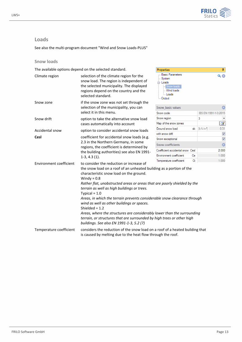
Snow loads The available options depend on the selected standard.
Climate region selection of the climate region for the snow load. The region is independent of the selected municipality. The displayed regions depend on the country and the selected standard.
Snow zone if the snow zone was not set through the selection of the municipality, you can select it in this menu.
Snow drift option to take the alternative snow load cases automatically into account
Accidental snow option to consider accidental snow loads
Cesl coefficient for accidental snow loads (e.g. 2.3 in the Northern Germany, in some regions, the coefficient is determined by the building authorities) see also EN 1991-1-3, 4.3 (1).
Environment coefficient to consider the reduction or increase of the snow load on a roof of an unheated building as a portion of the characteristic snow load on the ground. Windy = 0.8 Rather flat, unobstructed areas or areas that are poorly shielded by the terrain as well as high buildings or trees. Typical = 1.0 Areas, in which the terrain prevents considerable snow clearance through wind as well as other buildings or spaces. Shielded = 1.2 Areas, where the structures are considerably lower than the surrounding terrain, or structures that are surrounded by high trees or other high buildings. See also EN 1991-1-3, 5.2 (7)
Temperature coefficient considers the reduction of the snow load on a roof of a heated building that is caused by melting due to the heat flow through the roof.
Wind and Snow Loads
Page 14 Software for structural calculation and design
Wind loads See also the multi-program document "Wind and Snow Loads-PLUS".
The available options depend on the selected standard
Wind zone if the wind zone is not defined via the selection of the municipality, you can select it in this menu.
Terrain category selection of the terrain category (depends on the selected standard), see also EN 1991-1-4, tab. 4.1. Some national Annexes possibly specify additional mixed categories.
Category I: Lakes or areas with low vegetation and without obstructions.
Mixed category coast: Lakes, coastal areas bordering the open sea.
Category II: Areas with low vegetation, such as grassland and individual obstructions (trees, buildings) that have a distance of at least 20 times their height to each other.
Category III: Areas with uniform vegetation or development or with individual objects that are closer to each other than 20 times the obstacle height (e.g. villages, suburban development, forest areas).
Category IV: Areas of which 15 % of the surface is covered with buildings of medium height taller than 15 m.
Basic wind velocity to specify a value, disable the selection of the municipality (see above).
Basic velocity pressure the indicated value qb0 is determined by the basic wind velocity.
Interpolate load-application area you can optionally consider a user-defined load-application area between 1 m² and 10 m². Interpolation of the cpe values (1 to 10).
Inclination of the ground H/Lu specifies the value H/Lu in the flow direction. On isolated mountains, mountain chains or rocks, different wind speeds result from the slope of the ground surface. H refers to the height of the slope and Lu to the length of the slope, see also EN 1991-1-4, A.3 (1).
Orography factor factor as per EN 1991-1-4, figure A.2 for cliffs or offsets in the ground surface or A.3 for hilltops and hill crests, related to the effective length Le of the windward gradient.
Topography coefficient coefficient co as per EN 1991-1-4, 4.3.3. At places where the topography (e.g. mountains, cliffs etc.) increases wind speed by more than five percent, the speed increase is to be considered via the topography factor co.
CDir coefficient for the wind direction (only in combination with EN 1991).
CSeason seasonal factor (only in combination with EN 1991).
Loads Soil snow load allows you to adjust the soil snow load sk manually. If a municipality was
defined, the corresponding settings are disregarded, and the selection of the municipality is disabled.
Velocity pressure the velocity pressure for each direction (0°, 90°) is automatically set to default, but you can modify it for further calculations (check the option).
LWS+
FRILO Software GmbH Page 15
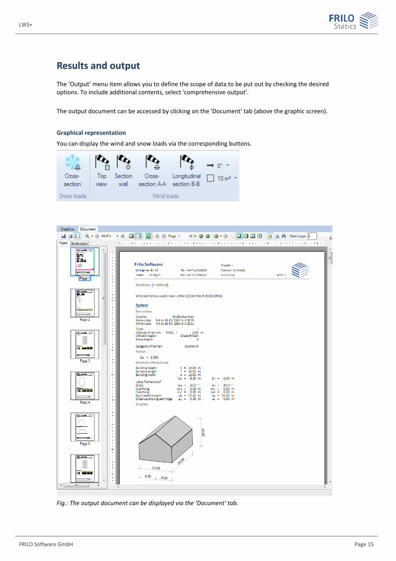
Results and output
The ‘Output’ menu item allows you to define the scope of data to be put out by checking the desired options. To include additional contents, select 'comprehensive output'.
The output document can be accessed by clicking on the 'Document' tab (above the graphic screen).
Graphical representation
You can display the wind and snow loads via the corresponding buttons.
Fig.: The output document can be displayed via the 'Document' tab.