welcome to the cim user group - ucaiugcimug.ucaiug.org/meetings/vasteras2008/cimug...
TRANSCRIPT

1
Welcome to the CIM User Group
CIM User Group Meeting Vesteras, Sweden
10 June 2008
2
CIM Tutorial - Outline
CIM 10101 Tutorial Introduction to CIM – Terry Saxton
• The CIM UML model and its role in the utility enterprise as a semantic model for information exchange
• CIM XML and messaging standards for information exchange including power system models
• Real world examples of use of CIM for information exchange02 GID Standards and Web services – Ralph Mackiewicz
Advanced CIM Topics03 CIM Message Construction with Business Context Layer – Terry
Saxton04 CIM Model Exchange – Jay Britton05 Business Process Modeling – Ralph Mackiewicz06 CIM User Group Benefits and New Web Site Launch – Randy
Rhodes

3
Introduction to CIM And Its Role in the Utility Enterprise
Data Preparation, Exchange, Integration, and Enterprise Information Management
CIM User Group Meeting Vesteras, Sweden
10 June 2008

4
Presentation Contents
• What is the CIM• How the CIM is used in the Utility Enterprise
– As a semantic model for information exchange• Overview of CIM Standards and IEC TC57
– CIM UML model– CIM XML for information exchange
• Power system models• Messages
• Benefits of using the CIM• Status of implementations• Real world examples
– EMS replacement project for an IOU– Market Redesign project for an ISO using a SOA– CIM-Based System Integration at Pacificorp– Texas Nodal Market Design

5
The IEC Common Information Model (CIM) - What Is It?• A Unified Modeling Language (UML) based information model representing
real-world objects and information entities exchanged within the value chain of the electric power industry
– Maintained by IEC in IBM’s Rational Rose and Sparx Enterprise Architect modeling tools
• Enable integration of applications/systems– Provides a common model behind all messages exchanged between systems– Basis for defining information exchange models
• Enable data access in a standard way– Common language to navigate and access complex data structures in any
database• Provides a hierarchical view of data for browsing and access with no knowledge of actual
logical schema– Inspiration for logical data schemas (e.g., for an operational data store)
• Not tied to a particular application’s view of the world– But permits same model to be used by all applications to facilitate information
sharing between applications– Also provides consistent view of the world by operators regardless of which
application user interface they are using

6
Sample Power System Model
Generator AC Line Substation
Company
Load
Operates
Operates
Belongs To
Member Of
Owns
Load Area
Connects To
Connects To
Connects To

7
Application of Information Model
SISCO SYSTEMS
Common model creates understanding
Application 1 Application 2
Mode
l Map
ping
Mode
l Map
ping

8
The CIM and Related Standards
• But the CIM is more than an information model standard expressed in UML
• It can be expressed in XML to create serialized files and messages– Standards for power system models– Standards for information message payloads
• There are a set of services known collectively as the Generic Interface Definition (GID)
• It can be extended– Standard extensions for new functional areas– Private extensions for specific utility requirements

9
What Role Does the CIM Play in the Utility Enterprise?• Data preparation
– Provides common set of semantics and data representation regardless of source of data
– Improves data quality and enables data validation• Data exchange
– Provides common language and format– Provides common set of services for sharing data
• System integration– Provides basis for a standards-based integration framework
• Web services payloads and Service Oriented Architecture (SOA)
• Enterprise Information Management– Part of overall Enterprise Information Model relating to business
processes/automation/management

10
Information is Needed From Many “Islands of Automation”
AM/FM/GIS
Mobile
SCADA
Work Mgmt
CustomerInformation
NetworkManagement
Maintenance& Inspection
HRFinancial
ContractManagement
ProtectionAsset
Planning
RiskAnalysis
NetworkPlanning
Historian OutageManagement
PropertyMgmt Compliance
The CIM
VENDORHELP!

11
Fixing the babbling among business systems
“The building of thetower of Babel”
by Pieter Bruegel, 1563 Oil on oak panel, KunsthistorischesMuseum, Vienna
Babble:to utter meaningless or unintelligible sounds[Merriam-Webster]
"If as one people speaking the same language they have begun to do this, then nothing they plan to do will be impossible for them.”[Bible]

12
The Common Language Should Provide Relevant Information To A User Regardless of Source
EngineeringConcerns
MaterialsManagement
ConcernsConstruction
Concerns
OperationsConcerns
ProtectionConcerns
MaintenanceConcerns

13
The Needs of Various Users – Some Same, Some Different
Engineering Concerns The logical view of how the type of equipment fits (will fit) in the electrical network. Nominal configuration of “as-built” and “future” states. • Field Name • Spatial Location • Version • Physical Connectivity • Load Projections • Capacity Requirements • Compatible Unit • Equipment Ratings
Construction Concerns Lifecycle information regarding when and how to install equipment: • Field Name • Location • Equipment Manufacturer/Model • Compatible Unit • Equipment Ratings • Work Order • Work Design • Installation Schedule &Budget • Permits • Manufacturer Specifications • Safety Requirements
Materials Management Concerns Planning and tracking material requirements for construction and maintenance. Information about physical pieces of equipment. • Asset Identifier • Compatible Unit • Equipment Component Type • Equipment Manufacturer/Model • Serial Number • Location • Equipment Location History • Manufacturer Specifications

14
The Needs of Various Users – Some Same, Some Different (continued)
Operations Concerns Real-time condition of equipment and electrical network necessary to maintain reliable network operation: • Field Name • Schematics & Spatial Location • Electrical Connectivity • Operational Limits (dynamic) • Equipment Status • Clearances • Network Measurements (voltage,
current, frequency) • Equipment Faults • Weather Measurements • Operational Restrictions
Maintenance Concerns Lifecycle information regarding when and how equipment is maintained: • Field Name • Location • Equipment Manufacturer/Model • Equipment Ratings • Routine Maintenance • Testing & Diagnostics
Procedures • Equipment Condition • Inspection Schedule • Equipment Repair Records • Site Service Records • Maintenance Budget • Safety Requirements
Protection Concerns Setting and configuring relays based on equipment and network protection requirements: • Field Name • Schematics • Electrical Connectivity • Maximum Capacity • Zones Of Protection • Equipment Status • Clearances • Network Measurements
(voltage, current, frequency, transients)
• Equipment Faults
15
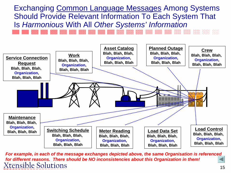
Exchanging Common Language Messages Among Systems Should Provide Relevant Information To Each System That Is Harmonious With All Other Systems’ Information
WorkBlah, Blah, Blah,
Organization,Blah, Blah, Blah
MaintenanceBlah, Blah, Blah,
Organization,Blah, Blah, Blah Switching Schedule
Blah, Blah, Blah, Organization,
Blah, Blah, Blah
Load Data SetBlah, Blah, Blah,
Organization,Blah, Blah, Blah
Meter ReadingBlah, Blah, Blah,
Organization,Blah, Blah, Blah
Load ControlBlah, Blah, Blah,
Organization,Blah, Blah, Blah
Asset CatalogBlah, Blah, Blah,
Organization,Blah, Blah, Blah
CrewBlah, Blah, Blah,
Organization,Blah, Blah, Blah
Service ConnectionRequest
Blah, Blah, Blah, Organization,
Blah, Blah, Blah
Planned OutageBlah, Blah, Blah,
Organization,Blah, Blah, Blah
For example, in each of the message exchanges depicted above, the same Organisation is referenced for different reasons. There should be NO inconsistencies about this Organization in them!

16
For example, a common language-based logical infrastructure facilitates collaboration among the many applications involved in Asset Management
Asset Strategy
Asset Portfolios
Risk Management
RegulatoryReporting
Financial Management
ResourceScheduling &
Planning
Equip./FleetManagement
Supply Chain Management
ContractManagement
Mobile Workforce
Mgmt.
Work Collaboration & Reporting
Work Design
Asset OwnerAsset Owner Asset ManagerAsset Manager Service ProviderService Provider
Asset Investment PlanningAsset Investment Planning Asset Program ManagementAsset Program Management
Customer ManagementCustomer Management Asset OperationsAsset Operations
CIS
CRM
IVR eBusiness EMS DMS
SCADA
OMS
Asset Planning Tool
Budget Load Forecast
ReliabilityAnalysis
NetworkAnalysis
Asset Repository
ExecutiveDashboard
Program Mgmt.
Work Mgmt.
Mobile & Dispatching
Contract Mgmt.
GISRevenue
Facility I&M
Portal
SA/DA
Metering
SRCM
[source: DistribuTECH 2003 paper by Zhou & Robinson]

17
Application To Common Language Mapping – The Typical Field to Field Process Is Cumbersome
• Individual fields of data models from data sources are mapped to each other
• Approach does not scale well as the number of maps grows exponentially with each new data source
• Mapping is a challenge as ‘mappers’ must have an in depth understanding of all relevant data sources – a tall order!

18
Using An Ontology To Simplify & Scale Up The Mapping Process
• What is an Ontology?– The key ingredients that make up an ontology are a vocabulary of basic
terms, a precise specification of what those terms mean and how they relate to each other.
• How is it used?– Before making mappings, a model (or an ontology) of a given business
domain is defined. – The model is expressed in a knowledge representation language and it
contains business concepts, relationships between them and a set of rules.
– By organizing knowledge in a discrete layer for use by information systems, ontologies enable communication between computer systems in a way that is independent of the individual system technologies, information architectures and applications.
– Compared to one-to-one mappings, mapping data sources to a common semantic model offer a much more scaleable and maintainable way to manage and integrate enterprise data.
[source: TopQuadrant Technology Briefing, July 2003]
19
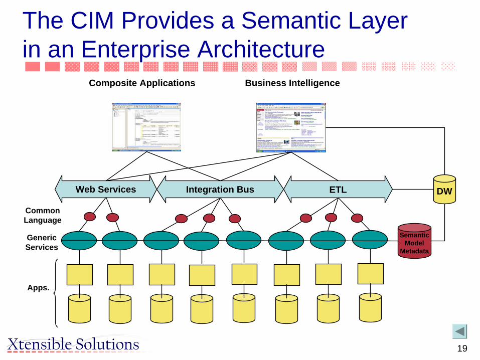
ETLIntegration BusWeb Services
Apps.
GenericServices
Composite Applications
DW
Business Intelligence
CommonLanguage
SemanticModel
Metadata
The CIM Provides a Semantic Layer in an Enterprise Architecture

20
FinancialGIS
Outage Management
DistWiresModel
GridWiresModel
DAC
CustomerInfo. System
VRU
Human Resources
DistributionAutomation
Data Warehouse
Planning Systems
IEC 61968 Compliant Middleware Services
Information Exchange
Model
Event HistoryWork
Management
...
EMS
= Interface Adapter TailoredFor Each Application
How Some Utility Implementations Are Using A Standards-Based Semantic Data Model
The “Common Language” provides a semantic layer based on the Utility’sEnterprise Semantic Model, which is derived from a combination of the IEC’s CIM, other applicable models, and necessary extensions

21
App CIMY.1 X.1Y.2 X.2Y.3 X.3Y.4 X.4Y.5 X.5
Publisher
Publishers:One Application Connector:•Obtains Data From Application And/Or Database•Transforms Data (if necessary) to the “CommonLanguage” (a Canonical Data Model)
•Puts Data Into Message Template•Publishes The Message (Fires & Forgets)
DataWarehouse
SubstationAutomation
OMS
DistWiresModel
GridWiresModel
DAC
CIS
VRU
AM/FM/GIS
DistributionAutomation
HumanResources
OutageReporting
Event History WorkManagement
EMS
...
CIMX.1 X.2 X.3 X.4 X.5
Subscriber
CIM AppX.1 B.1X.2 B.2X.3 X.4 X.5
Subscriber
CIM AppX.1 A.1X.2 X.3 X.4 A.4X.5 A.5
Subscriber
CIM AppX.1 C.1X.2 X.3 C.3X.4 C.4X.5
Subscriber
Subscribers:Several Application Adapters Receive The Same MessageEach Adapter:•Parses Message, Pulling Out Data Needed By Application•Transforms Data (if necessary) to Local Application Format•Passes Data To Local Application And/Or Database Through Most Appropriate Means
Message Type Instance: ChangedNetworkDataSet (Expressed In Common Language)
Decoupled InformationExchange
©
2003-2004 Xtensible Solutions, Inc. 21

22
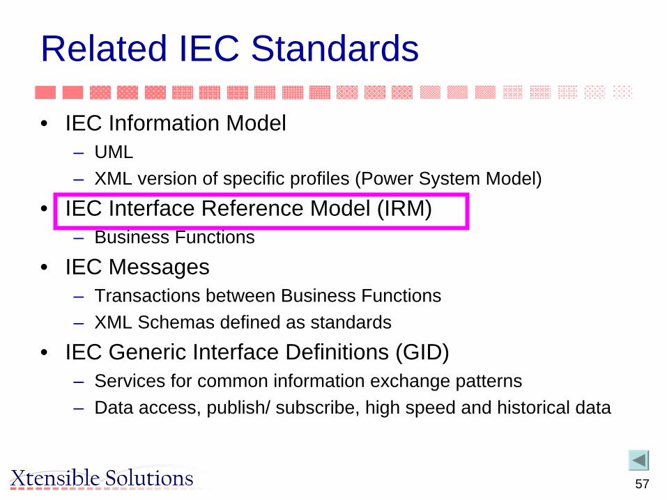
Related IEC Standards
• IEC Information Model– UML– XML version of specific profiles (Power System Model)
• IEC Interface Reference Model (IRM)– Business Functions
• IEC Messages– Transactions between Business Functions– XML Schemas defined as standards
• IEC Generic Interface Definitions (GID)– Services for common information exchange patterns– Data access, publish/ subscribe, high speed and historical data

24
Key Standards Key Standards and and RelatedRelated OrganizationsOrganizations
OLE ProcessControl(OPC)
WG14DMS
Coordination
WG19
WG13EMS
WGs 10Substations
Open Application
Group
WG7 Control Centers
TC57WG9
Distribution Feeders
EPRIUCA2ProjectEPRI
CCAPIProject
W3C
CIM/61850
ebXMLObjectMgmt.Group
WG17
WG16
WG18
OASIS
UCA : User groups
MultiSpeak(NRECA)
CIM

25
Related IEC Standards
• IEC Information Model– UML– XML version of specific profiles (Power System Model)
• IEC Interface Reference Model (IRM)– Business Functions
• IEC Messages– Transactions between Business Functions– XML Schemas defined as standards
• IEC Generic Interface Definitions (GID)– Services for common information exchange patterns– Data access, publish/ subscribe, high speed and historical data

26
Foundational Relationships Of The CIM
PowerSystemResourceElectrical Network Role Used For
Planning, Operations, etc.
AssetPhysical Plant Filling A Role
Such As A Transformer, Pole, etc.
LocationWhere To Find Something By
GPS, Address, Electronically, etc.
OrganisationEntities Performing Roles Such
As Operations, Tax Authority
ContactPeople Performing Roles SuchDispatcher, Field Operator, etc.
DocumentInformation Containers Such AsTrouble Ticket, Work Orders, etc.
CustomerIndustrial, Commercial, & Residential
Which Can Have Multiple Accounts

27
CIM Packages
Generation
Domain
Wires
LoadModel
Core
Meas
Topology
Outage Protection
Financial
Energy Scheduling
Reservation
SCADA
Core2
Assets Documen- tation
Consumer
OAG Messages
ERP Support
WG13
WG14

28
CIM Market Extensions
Security Constraints
Bid FTR
RTO
Clearing Results
Resource
WG16

29
Structureheight : ShortLengthweedAbate : BooleanweedRemDate : AbsoluteDatefumigant : StringfumigantApplyDate : AbsoluteDatejpaRefNum : String
Asset
code : Stringutc : Stringnumber : StringserialNumber : SerialNumberassetType : StringmaufacturedDate : AbsoluteDateinstallationDate : AbsoluteDateinServiceDate : AbsoluteDateoutOfServiceDate : AbsoluteDateremovalDate : AbsoluteDatewarrantyDate : AbsoluteDatefinancialValue : Moneystatus : StringstatusDate : AbsoluteDatecritical : BooleancorpStandard : StringremovalReason : Stringcondition : StringplantTransferDate : AbsoluteDateusage : StringpurchaseDate : AbsoluteDatepurchasePrice : MoneypurchaseOrderNumber : String
(from AssetBasics)
Pole
classification : Stringspecies : Stringtreatment : Stringbase : Stringpreservative : StringtreatedDate : AbsoluteDatebreastBlock : Boolean
Streetlight
rating : StringarmLength : ShortLength
0..1
0..n
+AttachedTo_Pole
0..1 +Support_Streetlights0..n
The CIM Is Expressed In Unified Modeling Language (UML) Notation*
Class Name usually describes things in the real world
Associations connect classes and areassigned a role that describes the relationship
Class Attributes describesignificant aspects about the thing
This Specialization indicates that a “Pole” is a type of“Structure.” Since a “Structure” is a type of “Asset,” the Poleinherits all of the attributes from both Structure and Asset
* For more information on UML notation (a standard), refer to Martin Fowler’s book“UML Distilled,” Addison-Wesley

30
Concepts: Generalization/Inheritance
• Breaker: Specialization of Switch
• Switch: Specialization of Conducting Equipment
• ConductingEquipment: Specialization of PowerSystem Resource
Breaker
ConductingEquipment(from Core)
PowerSystemResource(from Core)
Switch
PowerTransformer
Naming(from Core)

31
Equipment Inheritance Hierarchy
PowerSystemResource(from Core)
Conductor
Ground
Jumper
Junction
RectifierInverter
RegulatingCondEq
StaticVarCompensator
Fuse
TransformerWinding
TapChanger
Disconnector
LoadBreakSwitch
DCLineSegment
ACLineSegment
ShuntCompensator
VoltageControlZone
BusbarSection
HeatExchanger
Bay(from Core)
VoltageLevel(from Core)
PowerTransformer
EquipmentContainer(from Core)
Equipment(from Core)
SynchronousMachine
Breaker
ConductingEquipment(from Core)
GroundDisconnector
EnergyConsumer
Substation(from Core)
EnergySource
Switch
CompositeSwitch
Connector
FrequencyConverter
LinePlant
SubControlArea(from Core)
IdentifiedObject(from Core)
ProtectedSwitch
SeriesCompensator
ConnectivityNodeContainer(from Core)

32
Equipment Containers
Plant
PowerSystemResource(from Core)
EquipmentContainer(from Core)
Equipment(from Core)
0..1
0..n
+MemberOf_EquipmentContainer0..1
+Contains_Equipments0..n
GeographicalRegion(from Core)
Line
SubGeographicalRegion(from Core)
0..1
0..*
+Region 0..1
+Regions 0..*
0..1
0..*
+Region0..1
+Lines0..*
VoltageLevel(from Core)
Bay(from Core)
0..1
0..n
+MemberOf_VoltageLevel 0..1
+Contains_Bays 0..n
Substation(from Core)
0..1
0..*
+Region
0..1
+Substations
0..*
1
0..n
+MemberOf_Substation 1
+Contains_VoltageLevels 0..n
0..n
0..1
+Contains_Bays
0..n
+MemberOf_Substation0..1
IdentifiedObject
aliasName : Stringdescription : Stringname : StringpathName : StringmRID : String
(from Core)

33
Connectivity Model
Bus/Branch Model
Switch/Node Model
IdentifiedObject(from Core)
PowerSystemResource(from Core)
TopologicalIsland
ConductingEquipment(f rom Core)
Measurement(f rom Meas)
TopologicalNode
1
1..n
+TopologicalIsland1
+TopologicalNodes1..n
Terminal(f rom Core)
0..n1+Terminals
0..n+ConductingEquipment
1
0..n
0..1
+Measurements0..n
+Terminal0..1
EquipmentContainer(from Core)
ConnectivityNode
0..n
0..1
+ConnectivityNodes0..n
+TopologicalNode0..1
0..n
0..1
+Terminals0..n
+ConnectivityNode0..1
1
0..n
+MemberOf_EquipmentContainer1
+ConnectivityNodes0..n

34
Simple Network Example
SS1
SS2
400KV
110KV
12345 MW
12345 KV
12345 MW
Cable1 Cable2
SS1-SS2
T1
BB1
SS4
Cable3

35
Simple Network Connectivity Modeled with CIM Topology
SS 1
Cable2
SS 2
110KV
400KV
Cable1 CN2CN3BR1DC2 CN4
P1(MW)
CN5
BB1
T 1
TW 1
TW 2
CN7
CN6
Volts(KV)
BR3
P2(MW)
CN1
SS1-SS2
Cable3
SS 4
CN8
36
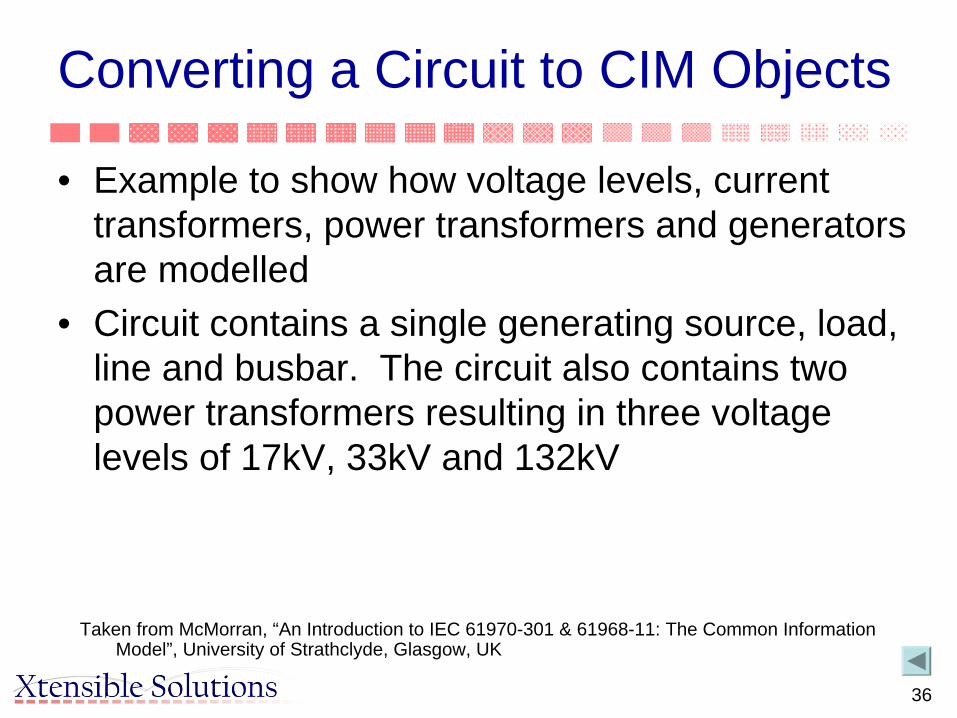
Converting a Circuit to CIM Objects
• Example to show how voltage levels, current transformers, power transformers and generators are modelled
• Circuit contains a single generating source, load, line and busbar. The circuit also contains two power transformers resulting in three voltage levels of 17kV, 33kV and 132kV
Taken from McMorran, “An Introduction to IEC 61970-301 & 61968-11: The Common Information Model”, University of Strathclyde, Glasgow, UK

37
Example Circuit as a Single Line Diagram
EnergyConsumer
Breaker
SynchronousMachine
GeneratingUnit
Breaker
BusbarSection
Breaker
ACLineSegment

38
Representing a Power Transformer as CIM Objects• A power transformer is not mapped to a single
CIM class– Represented by a number of components with a single
PowerTransformer container class– Two-winding power transformer becomes two
TransformerWinding objects within a PowerTransformer container
• If a tap changer is present to control one of the windings– An instance of the TapChanger class is associated
with that particular winding– Also contained within the PowerTransformer instance

39
Transformer Class Diagram
Inherits from Equipment, since does not conduct
electricity
Physically connected to network and conducts electricity, so inherits
from ConductingEquipment
Part of TransformerWinding, not
separate piece of equipment
Shell of transformer, containing windings,
insulation, magnetic core, etc.

40
CIM Mapping for Transformer 17-33
• Transformer 17-33 is represented as four CIM objects

41
Example Circuit as a Single Line Diagram
EnergyConsumer
Breaker
SynchronousMachine
GeneratingUnit
Breaker
BusbarSection
Breaker
ACLineSegment
Current measurement represented by Measurement
connected to Terminal

42
Example Circuit with Full CIM Mappings
• Maps to– 17 CIM classes– 45 CIM objects
• Could be extended further with addition of objects for
– control areas– equipment
owners– measurement
units– generation and
load curves– asset data

43
Transformer Model Diagram from 61970-301CIM Base
ConductingEquipment(from Core)
Equipment(from Core)
PowerSystemResource(from Core)
RegulationSchedule
TapChanger
0..1
0..n
+RegulationSchedule0..1
+TapChangers0..n
WindingTest
HeatExchanger
TransformerWinding
0..n+TapChangers
0..n
+TransformerWinding
1
1
0..n
+From_TransformerWinding1
+From_WindingTests1
0..n
+To_WindingTest
+To_TransformeWindings0..n
PowerTransformer
0..1
1
+HeatExchanger0..1
+PowerTransformer 1
1..n
1
+Contains_TransformerWindings
+MemberOf_PowerTransformer
1

44
Transformer Winding Attributes
Transformer Windingb: SusceptanceinsulationKV: VoltageconnectionType: WindingConnectionemergencyMVA : ApparentPowerg: Conductancegrounded: Booleanr: Resistancer0: ResistanceratedKV: Voltagerated MVA: ApparentPowerrground: ResistanceshortTermMVA: ApparentPowerwindingType: WindingTypex: Reactancex0: Reactancexground: Reactance
45
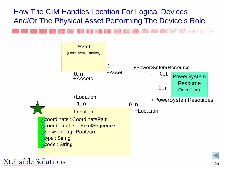
How The CIM Handles Location For Logical Devices And/Or The Physical Asset Performing The Device’s Role
Asset(f rom AssetBasics)
0..n+Assets
1..n
0..n
+Location1..n
Locationcoordinate : CoordinatePaircoordinateList : PointSequencepolygonFlag : Booleantype : Stringcode : String
0..n+Location
0..n
0..n+PowerSystemResources
0..n
PowerSystemResource(from Core)
0..1+PowerSystemResource1
0..1+Asset1

46
Top Of The Asset HierarchyOrgRoleAsset
privilege : StringroleType : StringpercentOwnership : Float
1..**
Organisation(f rom TopLev elPackage)
AssetModelnumber : Stringversion : String
0..n
0..1
Assetcode : Stringutc : StringserialNumber : SerialNum berassetType : StringmaufacturedDate : AbsoluteDatewarrantyDate : AbsoluteDatefinancialValue : Moneycri tical : BooleancorpStandard : Stringcondi tion : StringplantTransferDate : AbsoluteDateusage : StringpurchaseDate : AbsoluteDatepurchasePrice : MoneypurchaseOrderNumber : StringtestStatus : BooleanstatusDate : AbsoluteDatecurrentStatus : String
0..n
0..n
Document(f rom Document ationPa...)

47
Types Of Document Relationship Inherited By All Assets
AssetModelnumber : Stringversion : String
0..n
0..n
Document(f rom DocumentationPa...)
Quali ficationRequirem entqualificationID : String
AssetPropertypropertyType : StringpropertyValue : Stringunits : String
AssetRatingratingType : Stringproperty : StringratingValue : Floatunits : String
InspectionRoutine(f rom As setsIns pec tion)
MaintenanceProceduretype : String
0..n
0..n
PowerSystemResource(from Core)
48
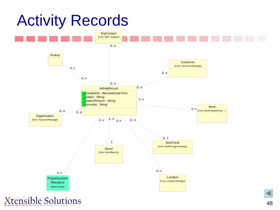
Activity Records
History
0..n
0..1
ErpContact(f rom ERP_Support)
0..n
0..n
ActivityRecordcreatedOn : AbsoluteDateTimestatus : StringstatusReason : Stringremarks : String
Customer(f rom ConsumerPackage)
0..n
0..n
0..n
0..n
0..n
0..1
0..n
0..n
Asset(f rom AssetBasics)
1..n
1
0..n
0..n
PowerSystemResource(from Core)
Location(f rom LocationPackage)
Organisation(f rom TopLev elPackage)
0..n 0..n
Work(f rom WorkInitiationPack...)
WorkTask(f rom WorkDesignPackage)

50
Questions?

51
Related IEC Standards
• IEC Information Model– UML
• Using the CIM to Define Information Exchanges– XML version of specific profiles (Power System Model)
• IEC Interface Reference Model (IRM)– Business Functions
• IEC Messages– Transactions between Business Functions– XML Schemas defined as standards
• IEC Generic Interface Definitions (GID)– Services for common information exchange patterns– Data access, publish/ subscribe, high speed and historical data

52
How CIM-Based Data is Exchanged
• Some form of serialization is needed– XML is most popular
• CIM UML has been translated into XML• RDF (Resource Description Framework) schema and
syntax used for CIM XML document– For exchanging power system models– Generated from the CIM Rational ROSE model using tools– NERC mandated use of this standard by Security Coordination
Centers to exchange power system models by September 2001
• XML Schema– For message-based information exchange between systems– Tools to automatically generate from UML

53
Power System Model Exchange
• Based on transmission part of CIM, NERC defined a profile to exchanging power system models– Common Power System Model (CPSM) profile defines
a subset of the CIM to be supported– CIM/XML using RDF schema defines how to express
this part of the CIM in XML– Interoperability tests have validated several vendor’s
products for exchanging complete power system models, partial models, and incremental updates

54
Basics: Schema from CIM
Rational ROSE
CIM (in UML)
UMLto RDF
Transformers
CIM as XML/RDF Schema
specifies
Power System Data
Exporter
Power System Data
as XML/RDF
references

55
The IEC Standards for Power System Model Exchange
• The CIM translated into the industry standard eXtensible Markup Language (XML):– Uses a standard XML format that any EMS can understand using
standard Internet and/or Microsoft technologies– Automatically generated from the CIM Rational ROSE model
• IEC 61970 series of standards– Part 301 CIM Base
• Specifies UML model– Part 452 CIM Model Exchange Specification
• Specifies guidelines for the definition of specific profiles (or subsets) of the CIM for particular power system model exchange requirements
– Part 501 CIM RDF Schema• Specifies mapping between UML model and XML model using RDF Schema• This was mandated by NERC for exchange of models between Reliability
Coordinators– Part 552-4 CIM XML Model Exchange Format
• Specifies simplified RDF Schema and extensions to transfer incremental updates via difference file
56
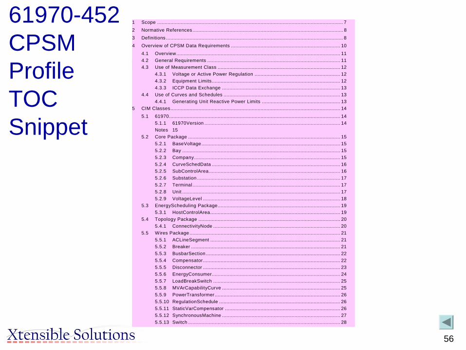
61970-452 CPSM Profile TOC Snippet
1 Scope .............................................................................................................................. 72 Normative References...................................................................................................... 8 3 Definitions ........................................................................................................................ 8 4 Overview of CPSM Data Requirements .......................................................................... 10
4.1 Overview............................................................................................................... 11 4.2 General Requirements .......................................................................................... 11 4.3 Use of Measurement Class ................................................................................... 12
4.3.1 Voltage or Active Power Regulation .......................................................... 12 4.3.2 Equipment Limits....................................................................................... 12 4.3.3 ICCP Data Exchange ................................................................................ 13
4.4 Use of Curves and Schedules ............................................................................... 13 4.4.1 Generating Unit Reactive Power Limits ..................................................... 13
5 CIM Classes................................................................................................................... 14 5.1 61970.................................................................................................................... 14
5.1.1 61970Version ............................................................................................ 14 Notes 15
5.2 Core Package ....................................................................................................... 15 5.2.1 BaseVoltage.............................................................................................. 15 5.2.2 Bay ........................................................................................................... 15 5.2.3 Company................................................................................................... 15 5.2.4 CurveSchedData ....................................................................................... 16 5.2.5 SubControlArea......................................................................................... 16 5.2.6 Substation ................................................................................................. 17 5.2.7 Terminal .................................................................................................... 17 5.2.8 Unit ........................................................................................................... 17 5.2.9 VoltageLevel ............................................................................................. 18
5.3 EnergyScheduling Package................................................................................... 19 5.3.1 HostControlArea........................................................................................ 19
5.4 Topology Package ................................................................................................ 20 5.4.1 ConnectivityNode ...................................................................................... 20
5.5 Wires Package ...................................................................................................... 21 5.5.1 ACLineSegment ........................................................................................ 21 5.5.2 Breaker ..................................................................................................... 21 5.5.3 BusbarSection ........................................................................................... 22 5.5.4 Compensator............................................................................................. 22 5.5.5 Disconnector ............................................................................................. 23 5.5.6 EnergyConsumer....................................................................................... 24 5.5.7 LoadBreakSwitch ...................................................................................... 25 5.5.8 MVArCapabilityCurve ................................................................................ 25 5.5.9 PowerTransformer..................................................................................... 26 5.5.10 RegulationSchedule .................................................................................. 26 5.5.11 StaticVarCompensator .............................................................................. 26 5.5.12 SynchronousMachine ................................................................................ 27 5.5.13 Switch ....................................................................................................... 28
57
Related IEC Standards
• IEC Information Model– UML– XML version of specific profiles (Power System Model)
• IEC Interface Reference Model (IRM)– Business Functions
• IEC Messages– Transactions between Business Functions– XML Schemas defined as standards
• IEC Generic Interface Definitions (GID)– Services for common information exchange patterns– Data access, publish/ subscribe, high speed and historical data

58
MeterReading &
Control
MeterReading &
Control
Utility ControlCenter
Utility ControlCenter
NetworkExpansionPlanning
NetworkExpansionPlanning
CustomerInquiry
CustomerInquiry
NetworkOperationNetwork
Operation
Records& Asset
Management
Records& Asset
Management
OperationalPlanning &
Optimization
OperationalPlanning &
Optimization
IEC 61968CompliantInterface
Architecture
IEC 61968CompliantInterface
Architecture
Maintenance&
Construction
Maintenance&
Construction
UtilityBusinessSystems
(ERP, Billing,Energy trading,other systems)
UtilityBusinessSystems
(ERP, Billing,Energy trading,other systems)
Corporate LAN
Corporate LAN
Distribution AutomationDistribution Automation
Substation Protection,Monitoring and Control
Substation Protection,Monitoring and Control
RTU Communications RTU Communications
IEC TC57 Working Group 14:System Interfaces For Distribution Management
(responsible for IEC 61968 series of standards)
Information: www.wg14.com
Canada China Finland France Germany Netherlands Russian Federation Spain Sweden Switzerland South Africa United Kingdom United States Yugoslavia Japan

59
IEC TC57 WG14: Interface Reference Model (IRM) The Framework Used For Identifying Message Types
IEC 61968 Compliant Middleware Services
(NE)Network
ExtensionPlanning
(CS)CustomerSupport
(MR)Meter
Reading &Control
(AM)Records &
AssetManagement
(MC)Maintenance
&Construction
InterfaceStandard: Part 4
InterfaceStandard: Part 6
InterfaceStandard: Part 7
InterfaceStandard: Part 8
InterfaceStandard: Part 9
(ACT)CustomerAccount
Management
(FIN)Financial
(PRM)Premises
(HR)Human
Resources
(EMS)Energy
Management &Energy Trading
(RET)Retail
InterfaceStandard: Part 10
(SC)Supply
Chain andLogistics
(NO)Network
Operation
InterfaceStandard: Part 3
(OP)OperationalPlanning &
Optimization
InterfaceStandard: Part 5
InterfaceStandard: Part 10
InterfaceStandard: Part 10
InterfaceStandard: Part 10
InterfaceStandard: Part 10
InterfaceStandard: Part 10
InterfaceStandard: Part 10
Electric Distribution NetworkPlanning, Constructing,
Maintaining, and Operating
Generation and Transmission Management,Enterprise Resource Planning, Supply Chain, and
General Corporate Services
Business FunctionsExternal To Distribution
Management
Distribution ManagementBusiness Functions

60
Related IEC Standards
• IEC Information Model– UML– XML version of specific profiles (Power System Model)
• IEC Interface Reference Model (IRM)– Business Functions
• IEC Messages– Transactions between Business Functions– XML Schemas defined as standards
• IEC Generic Interface Definitions (GID)– Services for common information exchange patterns– Data access, publish/ subscribe, high speed and historical data

61
CIM Provides Vocabulary - CIM XML Provides Standard Messages
• Webster’s Dictionary = CIM– Provides standard data semantics and data types
• Sentence structure = CIM- based XML messages– Just as you must have structured sentences to communicate orally,
you must have standard messages to share data electronically• Standard messages are needed to
– Ensure interoperability both within and between utilities– Remove seams– Define that part of CIM that must be supported by an application
• Adapters provide CIM <-> proprietary data mappings used by applications

62
ControlHouseEquipment
CurveSchedData
CurveSchedFormula
CurveSchedule
0..n
0..1
+CurveScheduleDatas0..n
+CurveSchedule0..1
0..n
0..1
+CurveScheduleFormula0..n
+CurveSchedule
0..1
Naming
EquipmentContainer
Equipment
0..1
0..n
+MemberOf_EquipmentContainer
0..1
+Contains_Equipments0..n
CompanyPSRType
PowerSystemResource
0..n
0..n
+OperatedBy_Companies0..n
+Operates_PSRs0..n
0..1
0..n
+PSRType
0..1
+PowerSystemResource 0..n
SubControlArea
Substation
0..1
1..n
+MemberOf_SubControlArea0..1
+Contain_Substations1..n
Bay0..n
0..1
+Contains_Bays0..n
+MemberOf_Substation
0..1
Terminal
BasePower
VoltageLevel
1
0..n
+MemberOf_Substation1
+Contains_VoltageLevels0..n
0..1
0..n
+MemberOf_VoltageLevel0..1
+Contains_Bays0..n
ConductingEquipment
0..n
1
+Terminals0..n
+ConductingEquipment1
BaseVoltage
0..n
0..1
+BaseVoltage0..n
+BasePower0..1
0..n
1+VoltageLevel
0..n +BaseVoltage
1
0..n
0..1
+ConductingEquipment
0..n
+BaseVoltage0..1
Scheduling message
Incremental model update message
• Any part of model can be used in message
• All parts are inter-related to consistent reuse
• Ex: Can use just 10 classes from any part of CIM

63
Model Driven Information Exchange
• Think Model Driven Messaging– CIM provides semantic model– Define messages in UML based on CIM– Apply extensions and restrictions for specific utility
needs or to meet specified message content– Auto-generate XML schemas for message payloads– Translate at run-time to/from native XML schema

64
IEC TC57 WG14 Example: Integration Scenario for Extension Implementation

65

66

67
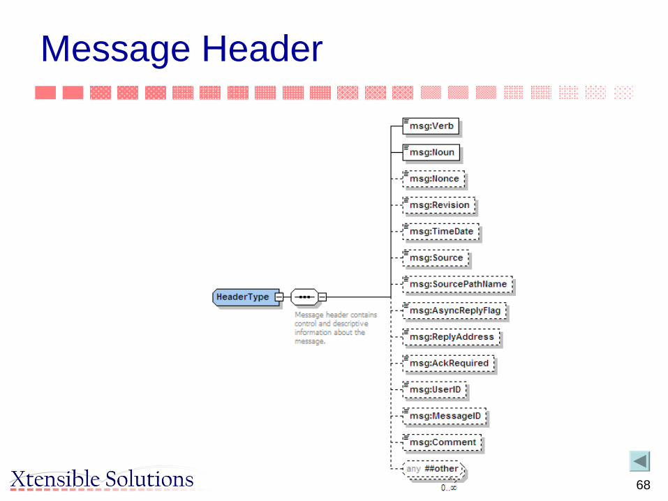
Basic Message Structure
68
Message Header

69
Example of Message Type Payload

70
How Message Elements are Derived from the CIM
Example CIM classes shown in UML notation
Message Type schemaderived from example CIM classes
ErpPerson(f rom ERP_Support)
0..n0. .n0. .n
+ErpPersons
+ScheduleSteps0..n
ScheduleSteprequiredControlAction : Stringins tructedDateTim e : AbsoluteDateTim ecom pletedDateTim e : AbsoluteDateTim estatus : Stringtext : Stringdes iredEndState : String
0..1
0..n+ScheduleSteps0..n
+Saf ety Document0..1
SafetyDocument

71
Testing for Compliance
• The IEC 61968 series of standard defines the logical names of message types and fields within message types
• Compliance can be assessed separately for each message type payload.
• A software component is deemed to be compliant to any specific message type if: 1. The component can produce a valid instance (typically expressed in
XML) of a message type (typically expressed in XSD) including all required fields with names and data types as defined in this standard.
• Data may be set to a default value if it is not available within a component• Optional data is passed in the appropriate optional fields. Message type
extensions are compliant as long as the correct CIM fields are used when applicable.
2. The component can read an instance of a message produced for a message type defined in this standard and correctly interpret the fields in the message

72
What Role Does the CIM Play in Sysem Integration?• Why do I care about the CIM?• Data preparation
– Provides common set of semantics and data representation regardless of source of data
• Data exchange– Provides common language and format– Provides common set of services for sharing data
• System integration– Provides basis for a standards-based integration framework
• Ex: Web services payloads and Service Oriented Architecture (SOA)
• Enterprise Information Management– Part of overall Enterprise Information Model relating to business
processes/automation/management

73
CIM Role in System Integration
• Business process models define system interactions• A common information model ensures consistent set of
business objects are exchanged, regardless of source– CIM provides a starting point– Utility adds classes, attributes, relations as needed to support
specific information requirements– Incorporate models from other sources– Result: Utility enterprise information model used as starting point
for message exchanges– Reality: Use where it makes sense
• Picture today– Many utilities have adopted an EAI middleware strategy and/or
product– But this is not enough

74
Information is Needed From Many “Islands of Automation”
AM/FM/GIS
Mobile
SCADA
Work Mgmt
CustomerInformation
NetworkManagement
Maintenance& Inspection
HRFinancial
ContractManagement
ProtectionAsset
Planning
RiskAnalysis
NetworkPlanning
Historian OutageManagement
PropertyMgmt Compliance

75
What’s Missing in EAI
• Provides transport mechanism to integrate islands of information
• But integration is more than putting all applications on an information bus
• Connectivity alone is not sufficient because:
– Each island (i.e., application) has own meaning of enterprise objects. Example:
• Transformer as asset vs. networked device
– Each island has data that overlaps data in other islands:
• Partial redundancy creates serious data integrity problem
– Each island has its own naming conventions

76
MeteringReading
SubstationAutomation
DistributionManagement
DistWiresModel
GridWiresModel
DAC
CustomerInformation
VRU
AM/FM/GIS
DistributionAutomation
ERP
DataWarehouse
“Application Integration” = Middleware + Common Language
OntologicalRepository
Event History WorkManagement
...
EMS
= Generic Adapter TailoredFor Each Application
How Some Utility Implementations Are Using A Standards-Based Semantic Data Model
The “Common Language” provides a semantic layer based on the Utility’sOntology, which is derived from a combination of the IEC’s CommonInformation Model (CIM), Other Applicable Models, and Necessary Extensions

77
How the CIM is Used to Enable Integration Based on a Semantic Model• Used to define a common language for the sharing information:
– Common language for all systems/applications to communicate via an integration bus
– Common model for accessing data in any database:• Permits navigating/browsing and formulating requests for data according to
the CIM model, not the internal database schema• Used to automatically generate XML based on the CIM:
– Files for sharing power system models – Standard XML message payloads based on CIM
• Model Driven Integration (MDI)– CIM provides semantic model for MDI– Define messages in UML based on CIM– Apply extensions and restrictions for specific utility needs– Auto-generate XML schemas for message payloads– Translate at run-time to/from native XML schema

78
MDI/CIM Aware Web Services or Adapters• EAI specific adapters and/or web services can be built
using MDI generic adapter services patterns– May require paradigm shift for EAI-certified integration
specialists• Decoupling is achieved through transformation to/from
the canonical message model• Interoperability is achieved through a common EAI
and/or Web Services based design and a common information model based message design
• Reusability and maintainability is achieved through using architectural patterns– Prime example: SOA

79
App CIMY.1 X.1Y.2 X.2Y.3 X.3Y.4 X.4Y.5 X.5
Publisher
Publishers:One Application Connector:•Obtains Data From Application And/Or Database•Transforms Data (if necessary) to the “CommonLanguage” (a Canonical Data Model)
•Puts Data Into Message Template•Publishes The Message (Fires & Forgets)
DataWarehouse
SubstationAutomation
OMS
DistWiresModel
GridWiresModel
DAC
CIS
VRU
AM/FM/GIS
DistributionAutomation
HumanResources
OutageReporting
Event History WorkManagement
EMS
...
CIMX.1 X.2 X.3 X.4 X.5
Subscriber
CIM AppX.1 B.1X.2 B.2X.3 X.4 X.5
Subscriber
CIM AppX.1 A.1X.2 X.3 X.4 A.4X.5 A.5
Subscriber
CIM AppX.1 C.1X.2 X.3 C.3X.4 C.4X.5
Subscriber
Subscribers:Several Application Adapters Receive The Same MessageEach Adapter:•Parses Message, Pulling Out Data Needed By Application•Transforms Data (if necessary) to Local Application Format•Passes Data To Local Application And/Or Database Through Most Appropriate Means
Message Type Instance: ChangedNetworkDataSet (Expressed In Common Language)
Decoupled InformationExchange
©
2003-2004 Xtensible Solutions, Inc. 79

80
Note: Paradigm Shift for Middleware
• Take Vitria BusinessWare for example– Centralized server typically used for
• Name correlation• Data type translation
– Requires multiple point-to-point mappings (i.e., Sys A to Sys B, Sys A to Sys C, etc.
– Defeats the use of the CIM as a common language• Instead need to put translation services in
interface adapters– Map only once at each adapter to/from CIM– No centralized bottleneck with subsequent
performance hits

81
Source
Transfer output data to native XML
Call transformation service
Transfer data to CIM XML
Bind to specific transport layer and publish the CIM XML message
Target
Transfer input data to native XML for specific call
Call transformation service
Get CIM XML data
Bind to specific transport layer and subscribe to the CIM XML message
Transport Layer
Messaging Persistence
Transformation
Exception Handling
Indexing & Referencing
Message Transport
Adapter Configuration
Common Services
Compliance Validation
Adapter Gateway
Management & Monitoring
MDI Generic Adapter Services

82
Message
Message Transport Service
Message
Send ReceiveAcknowledge
Sender Application
Header Header
Payload Payload
Adapter Gateway Service
Native XML (AUIDsender [i])
Datastore
Message Transport Service
Transport Layer
AUIDsender [i] MRID[i] MRID[i] AUIDreceiver[i]
Receiver Application
Adapter Gateway Service
AUIDsender [i]
Native XML (AUIDreceiver [i])
AUIDreceiver [i]Return AUIDreceiver [i], if new
Transformation Service
CIM XML (MRID[i])
Transformation Service
CIM XML (MRID[i])
Persistence Service Persistence Service
Indexing & Referencing Service
Indexing & Referencing Service
MDI Services in Request/Reply

83
What Role Does the CIM Play in Information Exchange?• Why do I care about the CIM?• Data preparation
– Provides common set of semantics and data representation regardless of source of data
• Data exchange– Provides common language and format– Provides common set of services for sharing data
• System integration– Provides basis for standards-based integration
• Enterprise Information Management– Part of overall Enterprise Information Model relating to business
processes/automation/management

84
ModelModel--Driven Business Information Driven Business Information ManagementManagement
BusinessModel
BusinessModel
Model business goals, objectives, organization structure, business functions, business concepts and terms and how they relate.
InformationSystems
Model
InformationSystems
Model
Model information systems that are providing the information technology foundation for executing business functions and processes.
Enterprise Information Management Governance ModelEnterprise Information Management Governance Model
“EIM Governance Model” provides Enterprise Information Management (EIM) governance policies, procedures, processes, and tools for meta-data and data management across business and IT. It also provides guidance on the structure, roles and responsibilities of the data management group and users of information, including configuration management, change management, etc.
BusinessProcessModel
BusinessProcessModel
Model business processes that may span across organization, business functions, and information systems.
EnterpriseSemantic
Model
EnterpriseSemantic
Model
Develop the Enterprise Semantic Model that will serve as the logical basis for all enterprise metadata and data management implementa- tions.
InformationUsageModel
InformationUsageModel
Model patterns and information usages (CRUD matrix, access, exchange, analysis, etc.) that support business functions and processes.
InformationUsage Design
InformationUsage Design
Design information usages using industry standards and best practices. Standards are critical to have a scaleable, flexible, and holistic EIM solution.
InformationUsage
Services
InformationUsage
Services
Implement the information usage designs in runtime environment. Leverage tools and packaged applications.

85
Questions?
86
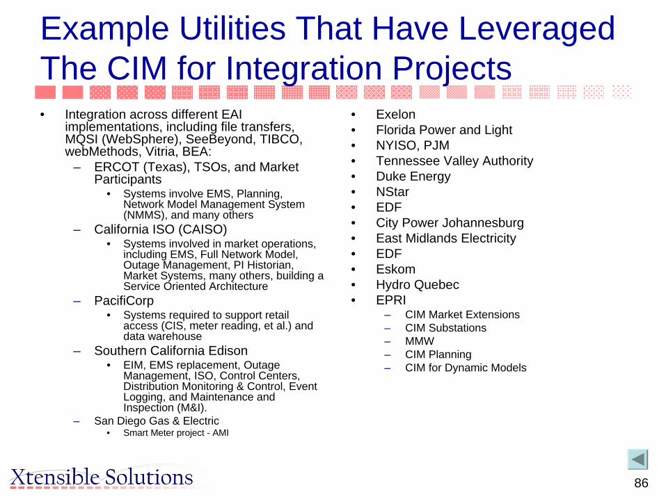
Example Utilities That Have Leveraged The CIM for Integration Projects• Integration across different EAI
implementations, including file transfers, MQSI (WebSphere), SeeBeyond, TIBCO, webMethods, Vitria, BEA:
– ERCOT (Texas), TSOs, and Market Participants
• Systems involve EMS, Planning, Network Model Management System (NMMS), and many others
– California ISO (CAISO)• Systems involved in market operations,
including EMS, Full Network Model, Outage Management, PI Historian, Market Systems, many others, building a Service Oriented Architecture
– PacifiCorp • Systems required to support retail
access (CIS, meter reading, et al.) and data warehouse
– Southern California Edison• EIM, EMS replacement, Outage
Management, ISO, Control Centers, Distribution Monitoring & Control, Event Logging, and Maintenance and Inspection (M&I).
– San Diego Gas & Electric• Smart Meter project - AMI
• Exelon• Florida Power and Light • NYISO, PJM• Tennessee Valley Authority• Duke Energy• NStar• EDF• City Power Johannesburg• East Midlands Electricity• EDF• Eskom• Hydro Quebec• EPRI
– CIM Market Extensions– CIM Substations– MMW– CIM Planning– CIM for Dynamic Models

87
Real World Examples of Use of CIM for Information Exchange• EMS Replacement Project at an IOU (SCE)
– CIM used as basis for enterprise information model and applied to individual projects as the need arises
• Market Redesign Project at an ISO (California ISO)– Service Oriented Architecture (SOA) implementation incorporating
the CIM as the enterprise information model
• CIM-Based Message Integration Framework at an IOU (PacifiCorp)– Integration strategy based on WG14 messaging
• Nodal Market Design at an ISO (ERCOT)– Single source for network model management and maintenance
for operations and planning

88
First Example: EMS Replacement Project• Southern California Edison (SCE) replaced EMS • Several external system interfaces that could
lead to multiple point-to-point links• Utility had already adopted the CIM at the
enterprise level and started an Enterprise Information Management (EIM) initiative based on the CIM as the utility’s business information model for common semantics
• Guidelines were in place for individual projects to fit into this overall enterprise integration strategy

89
EMS Replacement with MDI for External Interfaces
EAI Integration BusBased on Vitria BusinessWare Message Bus
EMS
Net
wor
k M
odel
Feed
er S
tatu
san
d A
nalo
gs
PlannedOutage Data(from ISO)Assets
Scheduling Systems- Generation- Interchange
Out
age
Dat
a
Pla
nned
Out
ages
Equ
ipm
ent
Ope
ratin
g Li
mits
Equ
ipm
ent L
imits
OMS
Sch
edul
es
Sch
edul
e
Feed
er S
tatu
s/A
nalo
g va
lues
External Power System
ApplicationsN
etw
ork
Mod
el
90
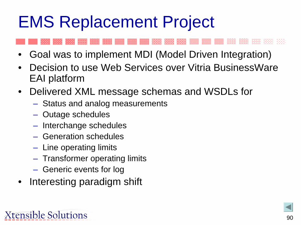
EMS Replacement Project
• Goal was to implement MDI (Model Driven Integration)• Decision to use Web Services over Vitria BusinessWare
EAI platform• Delivered XML message schemas and WSDLs for
– Status and analog measurements– Outage schedules– Interchange schedules– Generation schedules– Line operating limits– Transformer operating limits– Generic events for log
• Interesting paradigm shift

91
EMS Replacement Project
• Goal was to implement MDI (Model Driven Integration)• Decision to use Web Services over Vitria BusinessWare
EAI platform• Delivered XML message schemas and WSDLs for
– Status and analog measurements– Outage schedules– Interchange schedules– Generation schedules– Line operating limits– Transformer operating limits– Generic events for log
• Interesting paradigm shift

92
CIM Mapping for Interchange ScheduleExisting/
NewCIM Model Data Type Description Existing/
NewEMS Field Description Field Type Field
SizeField Value
E ProfileData.startDateTime AbsoluteDateTime
Date and time as "yyyy-mm-ddThh:mm:ss", which conforms with ISO 8601 using the extended form and any of the zone options.
E UTCTIME The time stamp associated with each tuple of transaction profile data.
DATE
E EnergyTransaction.name String Unique identifier among all interchange schedule transactions
E TID The unique transaction identification number associated with each tuple of data.
NUMBER 38
EN
Organization.nameDocOrgRole.roleType
String Name of sending utility.Role a company plays in a transaction. For example, for an interchange schedule, role could be SENDING UTILITY or RECEIVING UTILITY
E SENDUTILITY The abbreviated name of the selling utility.
VARCHAR2 4
EN
Organization.nameDocOrgRole.roleType
String Name of sending utility.Role a company plays in a transaction. For example, for an interchange schedule, role could be SENDING UTILITY or RECEIVING UTILITY
E RECVUTILITY The abbreviated name of the receiving utility.
VARCHAR2 4
E EnergyTransaction.typeTransaction
String Type of energy transaction, for example block or dynamic.
E TRANTYPE The abbreviated description of the energy transfer type.
VARCHAR2 4
E EnergyTransaction.description
String Description of the transaction E COMMENT Contains a brief description of the transaction. It can be updated through the operator interface.
VARCHAR2 80
E ProfileData.energyLevel EnergyAsMWH Energy level for the profile, in MWH.
E ENERGY The MWh value for the associated Tid during the associated time stamp.
NUMBER 22,10
E ProfileData.capacityLevel ActivePower Capacity level for the profile, in MW.
E CAPACITY The capacity value scheduled for the associated Tid during the associated time stamp.
NUMBER 22,10
E MessageHeader.source String Source of the message N PublishingSystemName
SCE system publishing outage data
String 12 char

93
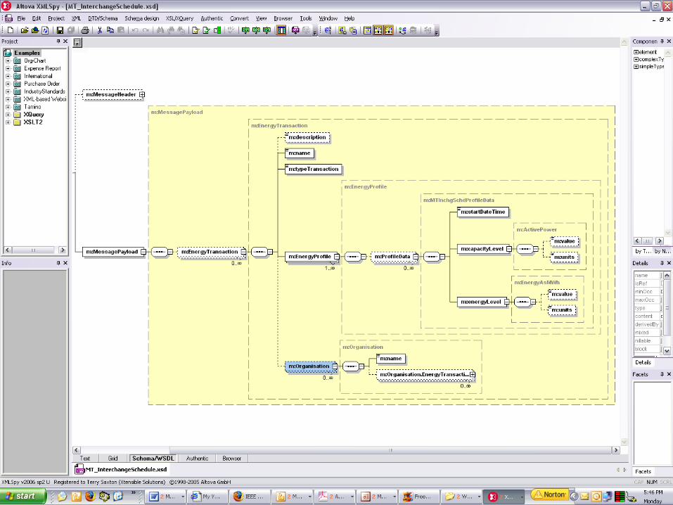
MT_InterchangeSchedule(f rom IEC61968-10 Energy Management and Energy Trading (EMS))
<<Root>>
EnergyProfile(f rom Energy Scheduling)
EnergyTransaction
firmInterchangeFlag : booleanstate : EnumeratedTypereason : StringenergyMin : ActivePowercongestChargeMax : MoneyreceiptPointMW : ActivePowerdeliveryPointMW : ActivePowertypeTransaction : String
(f rom Energy Scheduling)
1
0..n
1
0..n
1..n
1..1
1..n
1..1
ProfileData
sequenceNumber : IntegerstartDateTime : AbsoluteDateTimestopDateTime : AbsoluteDateTimecapacityLevel : ActivePowerenergyLevel : EnergyAsMWh
(f rom Energy Scheduling)
Profile(f rom Energy Scheduling)
0..n
0..n
0..n
0..n
Document(f rom DocumentInheritance)
Organisation
organisationCode : StringcurrentStatus : StringstatusDate : AbsoluteDateorganisationType : StringcostCenterFlag : booleanprofitCenterFlag : booleanmode : StringmarketRole : StringoptOut : boolean = "false"governmentID : String
(f rom TopLev el)
0..n 0..n0..n 0..n
DocOrgRole(f rom TopLev el)
Interchange Schedule• ProfileData.startDateTime
• EnergyTransaction.name
• "Organization.name• DocOrgRole.roleType“ - send
• "Organization.name• DocOrgRole.roleType“ - receive
• EnergyTransaction.typeTransaction
• EnergyTransaction.description
• ProfileData.energyLevel
• ProfileData.capacityLevel
• Final pruning of unneeded attributes done in tools, result in simple XML Schema

94
95

96

97
Second Example: Use of CIM/MDI Methodology to Implement a Service Oriented Architecture (SOA)
• CAISO designed a newpower market system– Multi-year program that involves many vendors, new systems, as
well as numerous legacy systems• Includes EMS, Full Network Model, Outage Management, PI
Historian, Market Systems, many others• External interfaces to Market Participants included
• Integration Competency Center decided on a Service Oriented Architecture (SOA) for the integration framework– Require all new applications and systems to be “Integration
Ready” with service-enabled interfaces– Use only standard CAISO-defined services– Payloads based on the CIM– Based on Web services– CIM and Model Driven Integration (MDI) methodology used to
define information exchange

98
Goals
• Data Integration– Enterprise Information Integration as Objective
• Business Process Orchestration– Unlocking of rigid processes through run-time
configuration as much as possible• The ISO is to achieve flexibility, scalability, and
cost savings through this approach
99
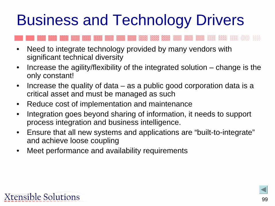
Business and Technology Drivers
• Need to integrate technology provided by many vendors with significant technical diversity
• Increase the agility/flexibility of the integrated solution – change is the only constant!
• Increase the quality of data – as a public good corporation data is a critical asset and must be managed as such
• Reduce cost of implementation and maintenance• Integration goes beyond sharing of information, it needs to support
process integration and business intelligence.• Ensure that all new systems and applications are “built-to-integrate”
and achieve loose coupling• Meet performance and availability requirements

100
Service-Oriented Architecture
Consumer
ProviderBroker
“Services”Repository
Discov
er Subscribe
Publish

101
Interface vs. Service
BA
Integration Layer
BroadcastService
transport
ReceiveService
ServiceOrchestrator
1 1
2
3

102
MDI/CIM Enabled Web Service Design
Common InformationModel (CIM)Process Models Message Models
(XSD)

103
Frameworks, Standards & Tools
Industry Standards(XML, XSD, RDF, XSLT, WSDL, SOAP/HTTP, UDDI, WS-I, CIM/CME, IEC 61967/61968)
SOAArchitecture
•SOA Patterns•SOA Conceptual
Architecture•Proof-of-Concept
Service & Payload Design Methods
•Service DefinitionMethodology
•MDI Framework•WS-I
Design Tools
•Rational Rose•MDI Workbench
•XML Suite•WSDL Tools
Configuration Management
•Documentum•VSS or Clear Quest
•UDDI Repository
Initiate Model Design Manage
(Slide from Stipe Fustar, KEMA)

104
Service Definition Approach
• BPMs– Gathering and reviewing business processes, systems,
applications, and databases information• Use Cases and Sequence Diagrams
– Develop/Elaborate To-Be service orchestration requirements in the forms of Use Cases and Sequence Diagrams
• CIM/CME– Develop common semantic based service payload definition in the
form of the UML diagram– Extend the CIM/CME, where necessary, to accommodate CAISO
requirements– The extended CIM/CME is the Common Semantic Model for the
MRTU program
(Slide from Stipe Fustar, KEMA)

105
• Payload - Create CIM base and service payload XML Schema files– Map source and target data format(s) to the common semantic
model based service payload definitions. Document any business rules of service payload and mappings
• Payload Template– Verify and validate XML Schema files, and create sample XML
instance data files for reference• WSDL
– Develop WSDL service definition files using a WSDL template, and validate WSDL files
• Document the service definition artifacts in one document for a given business integration (interface) area
Service Definition Approach (cont’d)
(Slide from Stipe Fustar, KEMA)

106
Interface Examples:Interface Type Example Implemented
byUtilized by Description
Information Creation
submitBid(XML) Vendor Enterprise These interfaces are for creating or modifying information within a system of record.
Information Transfer
publishCleanBidSet(XML) CAISO Vendor These interfaces are for transferring information and releasing custody.
Information Interest
receiveCleanBidSet(XML) Vendor EAI These interfaces are implemented by vendors to allow systems to receive information as it becomes available. This indicates a subscription type interest in data.
Information Sharing
getResourceInfo(XML) XML
Vendor Enterprise These interfaces are implemented by the vendors to surface information currently within custody to the enterprise.
(Slide from Stipe Fustar, KEMA)

107
System A Integration Layer
PI
BITS
MC
broadcastMarketMeterDataWS
retrieveMarketMeterData WS
broadcastMarketMeterData
WSretrieveMarketInterchange
WS
receiveMarketMeterDataWS
receiveMarketMeterDataWS
broadcastInvoiceData WS
broadcastGeneralLedgerData WS
receiveInvoiceData WS
receiveGeneralLedgerData WS
broadcastStatusInvoiceDataWS
(Slide from Stipe Fustar, KEMA)

108(Slide from Stipe Fustar, KEMA)

109(Slide from Stipe Fustar, KEMA)

111
CAISO Project Statistics
22 Systems• Dispatch System• MP Report Interface• Load Forecast• Transmission Capacity
Calculator• Real Time Nodal System• Settlement and Market
Clearing• Bid Interface and Validation• Forward Market Nodal
System• Energy Management
System7 Vendors• Siemens - Market Systems• ABB - EMS system• Areva - Settlement System• Legacy - CAISO system
• Default Energy Bids• Real Time Metering• Adjusted Metering• Market Participants
– Bidding– Market Results– Settlement– Outage Scheduling– Dispatch Signals
• Nexant - Congestion Revenue Rights System• MCG - Interchange Scheduling System• Potomac - Default Energy Bids
• OASIS• Interchange Scheduling
System• Congestion Revenue Rights• Intermittent Resources• Compliance• RMR Validation• Generation Outage Scheduling• Transmission Outage
Scheduling• Market Quality System
(ATF updates)
Appr 130 integrations between the 22 systemsAppr 75 message schemasAppr 175 service definitionsAppr 450 publisher/consumer testable data transfers between systems

112
To Summarize: Benefits of MDI/CIM Enabled SOA• Expose information through common mechanism and
common semantics• Seamless information flow across the enterprise• Deliver the right information at the right place at the right
time• Enforcing data quality and consistency at the service level• Flexibility/agility in responding to business organisation
and process changes • Technology agnostic• Utilizes widely adopted and proven standards• Reduce total cost of ownership• Provides traceability/mapping of business processes

113
Third Example – Pacificorp (R. Rhodes, B. Williams)• PacifiCorp is successfully using CIM to design both interfaces and
databases– CIM was adopted in 1999 as PacifiCorp’s application integration standard – Used for both messaging and database design for new projects– Existing interfaces are reworked when the need arises
• Model Driven Integration based on the CIM viewed internally as “Best Practice”– Having a common vocabulary reduces semantic misinterpretation– Reusing messages minimizes integration costs– Minimal knowledge of internal application designs required– Xtensible MDI Workbench used for message creation, management, and
maintenance • CIM is here to stay
– CIM is standard design practice– PacifiCorp vendors are getting used to the idea– PacifiCorp’s data warehouse is based on the CIM– EMS/SCADA system (Ranger) uses a CIM-based data maintenance tool

114
CIM Scorecard – Examples of CIM useBusiness Units
Application/Project
Message(s) CIM Pct of message that is CIM
Power Delivery
Substation Measurements
IntervalRead, SubstationEquipment.Measurement MeasurementList 90%
Outage Center Call Handing
TroubleCalls, TroubleReportAlerts, TroubleReportDetails, TroubleReportSummary, Customer Info, Customer Balance, Customer Account Balance
OutageManagement 80%
Retail Access Project
RegisterReadRequest, BillDeterminant, CustDrop, Enroll.DACust, EnrollmentChange, NonDACust, Reg.ESSRegister, Register.ESS, ESStatusChange, SESSESSRelationshipChange, RegisterReadResponse, CnIConsumption, DAEnrollConsumption, EnrollmentChange, NonDAEnrollConsumption, ESSStatusChange
CustomerMeterDataSet,CustomerServiceAgreement,MeasurmentList,Document, ActivityRecord, CustomerBilling, BillingDeterminant
80%
Pole Attachment System
FacilityPoint, JointUse.Agreement, JointUse.Attachment, JointUse.Notice, JointNoticeRequest, FacilityPoint
AssetList 70%
Transmission Transmission Planned Outages
PlannedOutage.Change PlannedOutageNotification 50%
Transmission Wholesale Billing System
TransmissionData, STLossData, LTLossData, Scheduling.LoadData,ConsumptionData, InvoiceData
Settlement and MarketClearing 70%
EMS SCADA WeatherData MeasurementList 100%

115
CIM Scorecard Cont’dBusiness Units
Application/Project
Message(s) CIM Pct of message that is CIM
Power Supply/Generation
Availability Information System
GeoThermalPlantGeneration MeasurementList 60%
Hydro Information Website
FlowDisplay MeasurementList 100%
Generation Equipment Performance Work Management
SolutionNotification, Performance, SolutionProject, EquipmentGroupRepetitiveTasks, Inventory.StockingPlan, WorkHistoryDocument
WorkWorkHistory
90%
Commercial & Trading
CRS MarkToMarketData MarkToMarket (Not in CIM) 80%
California ISO interface
EDI810 Settlement 50%
Corporate Giving Campaign
EmployeeDetails, ContributionPayrollDetails Employee (erpPerson) 70%
Sarbanes Oxley Audit
ChangeAuditReport ChangeAudit (Not in CIM) 90%

116
Fourth Example: Texas Nodal Market Implementation• The Electric Reliability Council Of Texas (ERCOT) charged with developing a
nodal market to replace the existing zonal market• Developing Network Model Management System (NMMS)
– A CIM-based repository for single source model network management for both Operations and Planning
• NMMS interfaces to most all downstream and upstream systems via CIM/XML based on RDF schema
– A CIM profile will be defined for each interface• Downstream systems include:
• EMS, CRR, OTS, MMS, Settlements and Billing, Outage Scheduler, Outage Evaluation, ICCP interface, Planning
• Market Information System interface to ERCOT members• Upstream systems include:
– Outage Scheduler– Generation Data from transmission service operators and generation entities– Network, SCADA & ICCP data from TSPs– Contingency, dynamic ratings and special protection schemes from TSPs– Planning changes from TSPs

117
ERCOT Nodal Program
• To accommodate all interface data requirements, the CIM was extended– Packages, classes, attributes and associations
• Other information exchanges directly between systems will use CIM XML schema-based messages loosely based on the 61968 message standards– TIBCO integration service bus will provide message
exchange infrastructure• Aggressive schedule to support Market-Go-Live
in 2009

118
CIM History
• 1992 – Unified Information turned over a data model based on the EPRI OTS to the CCAPI Task Force with the understanding it would be turned into an industry standard model.
• 1993 to 1996 - The CCAPI task force expanded the data model with a primary goal of enabling use of plug compatible applications to help protect utility investment in applications.
• 1996 – The CIM was turned over to IEC Technical Committee 57, Working Group 13&14, where it is advancing through the standards process. It covers both electric utility transmission and distribution business operations.
• 2003 – ISO/RTO Council and EPRI sponsored an initiative to expand CIM into Market Operations, a.k.a. CME.
• 2005 – First edition of IEC 61970-301 CIM Base• 2005 – CIM Users Group established under UCA Users Group.

119
CIM Usage• Many EMS vendors support power system model exchange using
CIM/RDF/XML, some with CIM-based databases behind the scenes• EPRI has sponsored nine interoperability tests for transmission model
exchange and GID GDA and HSDA validation• Utilities have implemented CIM-based integration using EAI technologies
– Utilities have used the CIM as the basis for developing common messages for integration
• Asset and work management vendors as well as GIS application vendors are starting to support CIM/XSD standards
• AMI vendors are starting to support IEC 61968 Part 9 for meter related information exchange
• CIM is being extended into the power market and planning, and provides a foundation for Service-Oriented Architecture (SOA) implementation
• Vendors have developed tools to build CIM-based information exchange messaging, GID interfaces, and repository applications that can process CIM- aware data
• EPRI and others sponsored many international workshops and seminars on CIM/GID standards

120
Benefits of Using CIM Approach
• Data model driven solutions leads to interoperability• Provides common semantics for information exchange between
heterogeneous systems– Used for CA to CA communications
• NERC mandated use of CIM and RDF Schema version for power system model exchange
• Provides for automatic generation of message payloads in XML– Ensures common language for all messages defined
• Single information model for all messages– Avoids proprietary message formats from vendors (based on internal
schemas)– Eliminates work of creating XML tags for each message– Alternative to EDI or CSV file formats

121
Benefits of Using CIM Approach
• Uses industry standard modeling notation– UML, XML
• Permits software tool use for:– Defining and maintaining data models
• Single point of maintenance for changes
– Documenting data models– Automatic generation of information payloads

122
CIM Acceptance
• In use at dozens of utilities throughout world– In NA, used at RTO/ISOs and NERC as well
• 50+ applications based on CIM• 40+ suppliers sell application/products based on CIM
– See CIM Reference List for Details• Endorsed by other standards organizations• Foundation for information exchange between utilities
and/or other external organizations• Foundation for Model-Driven Integration architecture
within an enterprise• CIM User Group to deal with questions and issues arising
from increased use

123
Recommendations
• Recommended process for incorporation of the CIM and related standards into planning – Create project or task force with interested parties – Develop use cases (with some examples) and identify
systems involved – Identify major data exchanges – Identify issues requiring resolution – Develop action plan
124
Questions?

126
Where to Get More Information About the CIM and Related Standards• Visit CIM User Group (CIMug) Web Site
– http://www.ucaiug.org/CIMug• Single site for gaining access to information about the CIM and related
standards– Includes all standards being developed by IEC TC57 Working Groups 13, 14, 16,
and 19• Now provide access to:
– Announcements of CIM-related activities and events – Calendar of activities – CIM electronic model in various formats – Lists of CIM-related tools and access to open source tools – Documents that are publicly available – Lists of the CIMug working groups and works in progress as well as minutes of
meetings and conference calls – CIM issues lists and status of resolution – Help desk – Discussion forums – Links to other CIM-related sites

127
CIM Status and Access Information
• CIM exists as electronic model and IEC standard (MS Word)– IEC 61970-301 CIM Base First Edition published
• Available from IEC online store– IEC 61968-11 CIM draft
• Available through WG14
• Complete CIM (61968 & 61970 packages in UML) available on CIMug Web site in various formats– Go to CIM Releases folder

128
Navigating the CIMug Web Site
• Two major parts to the web site:– Public access. Any one is free to browse and download
documents in this section. – Member only. Access to these parts requires a user name and
password which are obtained by joining the CIMug.
• If you have questions, probably the best place to start is the FAQs list under the Lists section on the left side of the home page. Here you will find answers to many questions about the CIM, the CIMug, the web site, and how to obtain information about joining the CIMug if you are not already a member, and how to obtain a user name and password if you are already a member.

129
Questions?
• Thank you