voltage-mode buck regulators - montefiore institute ulggeuzaine/elec0055/... · voltage mode -...
TRANSCRIPT

Voltage-Mode Buck Regulators

Voltage-Mode RegulatorVIN
COUT
RESR
RLOAD
L
RFB1
RFB2
VOUT
VREF
VFB
VP
ZC
+
-+-
T
VC
Output Filter
Error Amplifier
Modulator

Voltage Mode - Advantages and Disadvantages
• Advantages
1. Stable modulation/less sensitive to noise2. Single feedback path3. Can work over a wide range of duty cycles
• Disadvantages
1. Loop gain proportional to VIN
2. LC double pole often drives Type III compensation3. CCM and DCM differences - a compensation challenge4. Slow response to input voltage changes5. Current limiting must be done separately

Voltage Mode - Modulator Gain
P
INM V
VA =
VIN
VSW
+-
T VRAMP
VP
VC
VC

Voltage Mode - Output Filter
CO
RESR
RLOAD
LVOUTVSW
ZA
ZB
BA
B
SW
OUT
ZZZ
VV
+=
-40
-20
0
20
40
10 100 1,000 10,000 100,000 1,000,000
oω
ESRω
dB
Hz
* (Rx, Cy) indicate the components that drive the locations of the pole and the zero, detailed equations are in the notes
(L, Co)
(Resr, Co)
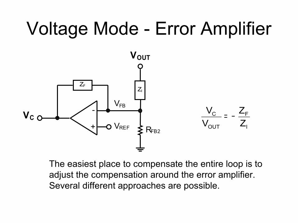
Voltage Mode - Error Amplifier
RFB2VREF
VFB
ZF
+
-
VOUT
VC
ZI
The easiest place to compensate the entire loop is to adjust the compensation around the error amplifier. Several different approaches are possible.
I
F
OUT
C
ZZ
VV −=
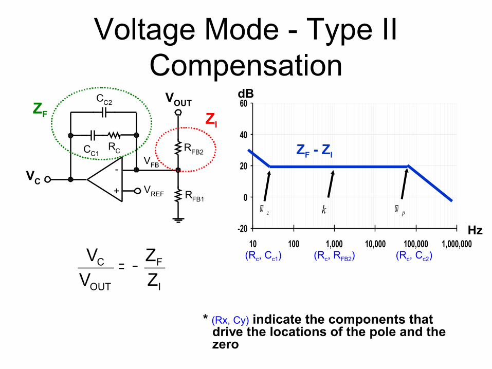
Voltage Mode - Type II Compensation
RFB2
RFB1VREF
VFB
+
-
VOUT
VC
RCCC1
CC2ZF ZI
I
F
OUT
C
ZZ
VV −=
-20
0
20
40
60
10 100 1,000 10,000 100,000 1,000,000
pωzω k
ZF - ZI
dB
Hz
* (Rx, Cy) indicate the components that drive the locations of the pole and the zero
(Rc, Cc1) (Rc, Cc2)(Rc, RFB2)

Voltage Mode - Type III Compensation
RFB2
RFB1VREF
VFB
+
-
VOUT
VC
RC1CC1
CC2
CC3
RC2
ZFZI
I
F
OUT
CZZ
VV −=
-20
0
20
40
60
10 100 1,000 10,000 100,000 1,000,000
1Pω1zω
k
2Pω
2zω
dB
Hz
(Rc1, Cc1)
(RFB2, Cc3)
(Rc1, Cc2) (Rc2, Cc3)
* (Rx, Cy) indicate the components that drive the locations of the poles and zeros,

Current-Mode Buck Regulators
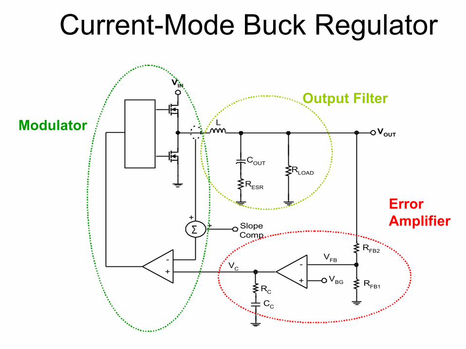
Current-Mode Buck Regulator
VIN
RC
CC
COUT
SlopeComp
RESR
RLOAD
L
RFB2
RFB1
VOUT
VBG
Σ+
+
VFBVC
+
-+-
Output Filter
Error Amplifier
Modulator

Current-Mode Buck-Regulator Architecture
+
-
PWM Comparator
VC
Corrective Ramp
VINModulator and Power Stage
T
Sn
Se
+ +
RS
VOUT Reference
A(s)+
-
Feedback, Error Amplifier ,and Compensation
RL
RC(ESR)
VOUTL
C+
-
Current SenseAmplifier
A i
T
DT
DT
Integrated or external

Current Mode - Advantages and Disadvantages
• Advantages1. Power plant gain offers a single-pole roll-off2. Line rejection3. Cycle-by-cycle current limiting protection4. Current sharing
• Disadvantages1. Noise2. Minimum ON-time3. Current Probe (Rsense, LEM, …)

CMC Sub Harmonic Oscillation
D =0.6
D = 0.33

Slope Compensation
=cm Internal Slope Comp
Stability criteriaC1
C2mmmm1
+−>
Vin
Vout Vin - Vout
25uA5u x (Vin - Vout)
A = 1
CONTROLTIMING
CRAMP
RAMPm1
m2

Current Mode - Output Filter
COUT
RESR
RLOAD
VOUTVSW
( )0.5DmLCf
1RC1ω Z
OUTsLOADOUTp1 −′+=
ESROUTz1 RC
1ω =

Current Mode - Error Amplifier
+
-
RC 1
CC1
VC
ROU T
Error Amplifier
gm
RFB1
VOUT
VREF
VFB
Compensation components internal in some devices
out
FB
fb2fb1
fb2FB V
VRR
RA =+
=
C1C1z2 RC
1ω =OUTC1
p2 RC1ω =
OUTmEA RgA =

Current Mode – Control Loop Gain
+
+
+
+
+
+
=
2s
2
sp2p1
z2z1DC
2ωs
2ωQ
s1ω
s1ωs1
ωs1
ωs1
ATComplex Pole @ Fsw/2
−+′
=D2
1mmDπ
1Q
1
CEA Pole
EA Zero
Output Filter Pole
Output Filter Zero
FBEACMDC AAAA =

Current-Mode Load Transients– Performance Tradeoffs
• Current mode control behaves like a current source driving the output capacitor
• The output impedance of a closed loop system is:
• Rule of thumb for high frequency load transients (tSLEW ≤ 1/fCROSSOVER):
where ZOUT is the impedance of the output capacitor at the crossover frequency
Loop_Gain1Z
Z _LOOPOUT_OPEN_LOOPOUT_CLOSED +
=
OUTOUTOUT ΔIZΔV =
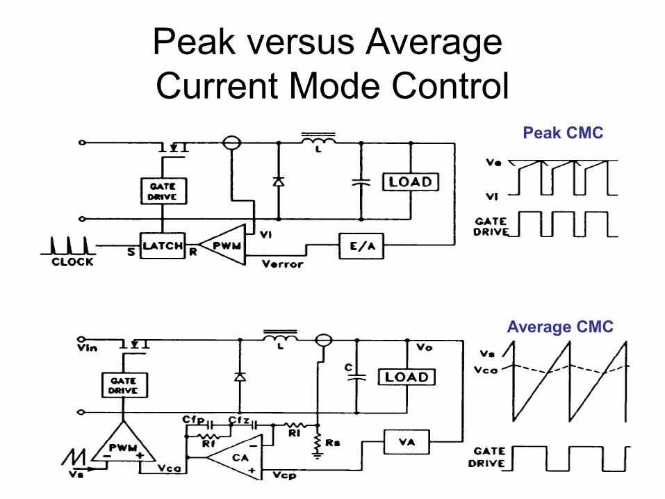
Peak versus Average Current Mode Control
Peak CMC
Average CMC
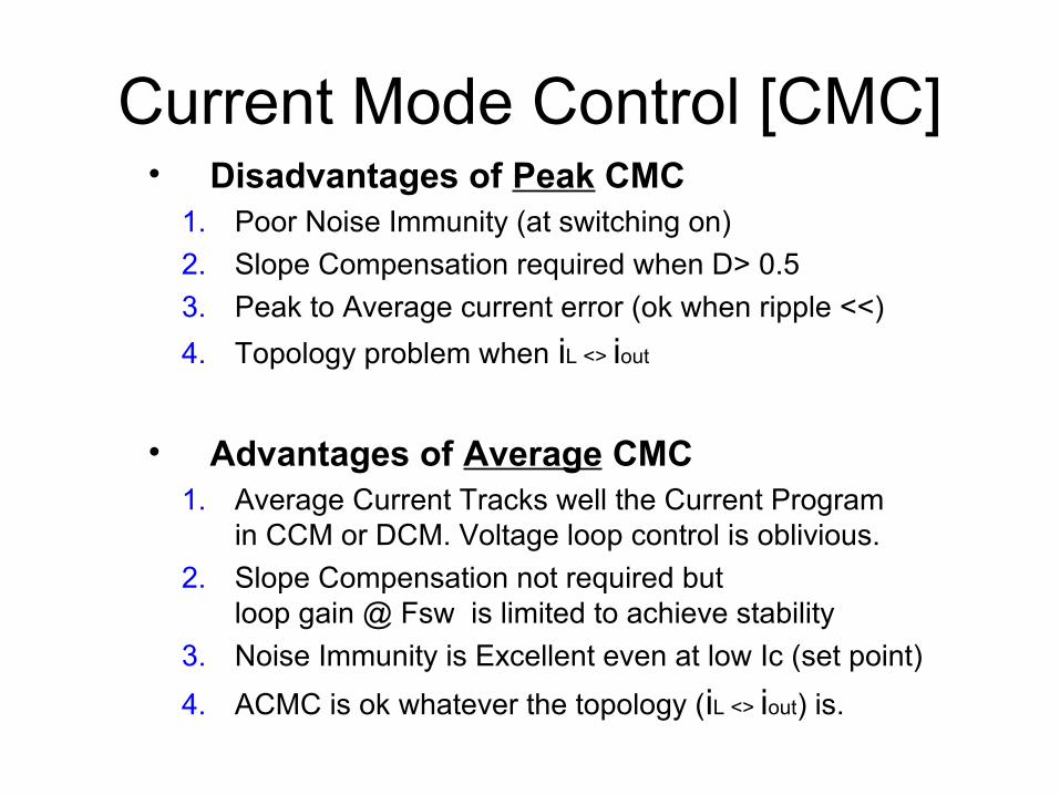
Current Mode Control [CMC]• Disadvantages of Peak CMC
1. Poor Noise Immunity (at switching on)2. Slope Compensation required when D> 0.53. Peak to Average current error (ok when ripple <<) 4. Topology problem when iL <> iout
• Advantages of Average CMC1. Average Current Tracks well the Current Program
in CCM or DCM. Voltage loop control is oblivious.2. Slope Compensation not required but
loop gain @ Fsw is limited to achieve stability3. Noise Immunity is Excellent even at low Ic (set point)4. ACMC is ok whatever the topology (iL <> iout) is.

Buck ACMC design example

Control Loop Gain at Fsw
The amplified current down slope Vca on the PWM comparator must be smaller
than the Oscillator ramp up slope
Current Amplifier Gain @ Fcrossover < Gstability
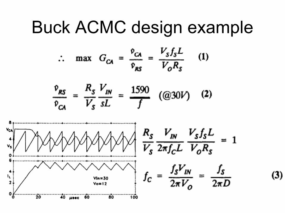
Buck ACMC design example

Buck ACMC design example