vlsi implementation of cordic based robot navigation … · eight mobile robots working within the...
TRANSCRIPT
International Research Journal of Engineering and Technology (IRJET) e-ISSN: 2395 -0056
Volume: 03 Issue: 02 | Feb-2016 www.irjet.net p-ISSN: 2395-0072
© 2016, IRJET | Impact Factor value: 4.45 | ISO 9001:2008 Certified Journal | Page 1282
VLSI IMPLEMENTATION OF CORDIC BASED ROBOT NAVIGATION PROCESSOR
P.KARTHIKEYAN[1] ,K.KAVASKAR[1],P.KIRBAKARAN[1],A.MANIKANDAN[1],R.ARUN SEKAR[2]
[1]BE Students, Department of Electronics & Communication Engineering
[2]Associate professor, Department of Electronics & Communication Engineering
S.N.S college of technology
ABSTRACT
This paper proposes the design of multiplier-less
processor through CORDIC algorithm and radio frequency
identification (RFID) technology for implementing the
VLSI architecture. The robot navigation ameans the ability
of the robot to establish its own position and orientation in
order to navigate from one place to destination. Xilinx ISE
design simulation tool and FPGA board kit are used for
realization the hardware schematic level and revels the
implementation in terms of speed delay and hardware
requirement. The performance of the processor could be
useful real time robotic navigation system application.
Keywords: robot navigation processor, CORDIC, RFID,
FPGA, RTL.
INTRODUCTION
In real-time applications of robot navigation which is
extensively used in the field of manufacturing automation
system and service of our daily needs in life these are more
types of navigation process position technique are
developed using sensor, camera, onboard component,
ultrasonic etc.by researches but, this method have some
disadvantages to overcome the problem, RFID technology
is proposed .
RFID is a term that describes a system with the
identification which uses CORDIC frequency to
communicate. RFID stands (Radio frequency
identification) the most important fact in the RFID is tag
(identification system attach to the item to be tracked)
reader system unit that can recognize the presence of
reader. There are two approaches to estimate the distance
based on signal strength and land mark based navigation.
The tags gains power from the electromagnetic pulse
which the reader transmits. They are quite thin lite and
low cost.
CORDIC stands for coordinate relational digital computer
which can perform electromagnetic related calculations
which are widely found in the broad range of applications.
CORDIC is utilized in multiplex less algorithm. CORDIC
algorithm is used to solve 2D vector station plane. Through
the algorithm we can divide large target rotation angle.
The work on robot navigation processor which is based on
CORDIC algorithm and with RFID technology on FPGA
platform. Collision detection is a part in CORDIC has been
applied for high through. We discuss how to implement
the CORDIC algorithm with FPGA model in Verilog HDL,
simulate and analysis the performance of processor.
The rest of the paper is as follows section II discuss the
CORDIC algorithm for its operating mode and
trigonometric function. The proposed scheme of RFID in
robot navigation processor in section III. section IV design
and simulation of processor is given, RTL view of designed
processor(section V) and finally conclusion of the paper in
section VI.
SECTION II
CORDIC ALGORITHM
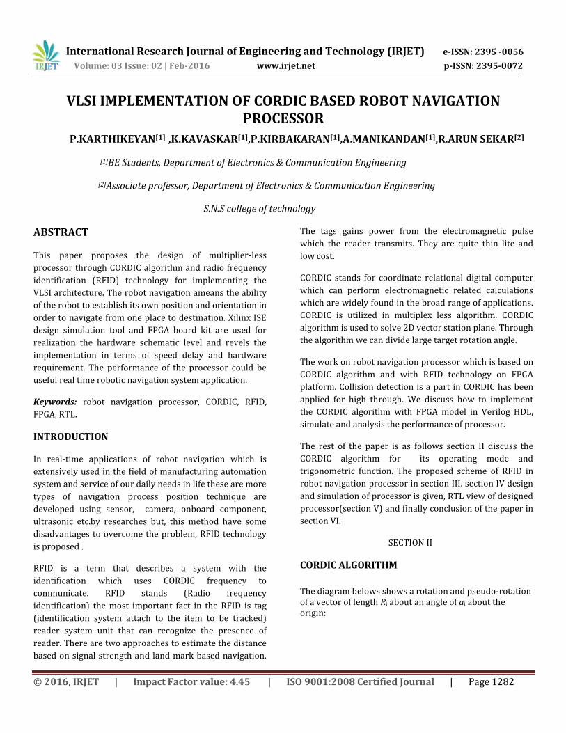
The diagram belows shows a rotation and pseudo-rotation of a vector of length Ri about an angle of ai about the origin:
International Research Journal of Engineering and Technology (IRJET) e-ISSN: 2395 -0056
Volume: 03 Issue: 02 | Feb-2016 www.irjet.net p-ISSN: 2395-0072
© 2016, IRJET | Impact Factor value: 4.45 | ISO 9001:2008 Certified Journal | Page 1283
A rotation about the origin produces the following co-ordinates:
Recall the identity.
Our strategy will be to eliminate the factor of
and somehow remove the
multiplication by . A pseudo-rotation produces a vector with the same angle as the rotated vector, but with a different length. In fact, the pseudo-rotation changes the length to:
Thus we now have these co-ordinates following a pseudo-rotation:
The pseudo-rotation has succeeded in removing our length-factor, which would have required a costly division operation. However, the vector will grow by a factor of K over a sequence of n pseudo-rotations:
The co-ordinates following the n pseudo-rotations are then:
CORDICs can be used to compute many functions. A
CORDIC has three inputs, x0, y0, and z0. Depending on the
inputs to the CORDIC, various results can be produced at
the outputs xn, yn, and zn.
Using CORDIC in rotation mode
For convergence of θn to 0, choose .
If we start with x0 = 1/K and y0=0, at the end of the process, we find xn=cos z0 and yn=sin z0.
The domain of convergence is
because 99.7° is the sum of all angles in the list.
Using CORDIC in vectoring mode

International Research Journal of Engineering and Technology (IRJET) e-ISSN: 2395 -0056
Volume: 03 Issue: 02 | Feb-2016 www.irjet.net p-ISSN: 2395-0072
© 2016, IRJET | Impact Factor value: 4.45 | ISO 9001:2008 Certified Journal | Page 1284
For convergence of yn to 0, choose.
If we start with x0 = 1 and z0 = 0, we find zn=tan−1y0
CORDICs can be used to compute many functions. A CORDIC has three inputs, x0, y0, and z0. Depending on the inputs to the CORDIC, various results can be produced at the outputs xn, yn, and zn.
SECTION III
PROPOSED DESIGN ASPECTS
In robot navigation there are multi-level environment is featuring an collision between them to overcome the problem we use the RFID technology which is fitted to robot with a writable active tag with data frame structure as shown in Fig.1 along with a RFID reader. For the tags fitted with static objects, ‘State bit’ is “00” and for dynamic tag ‘State bit’ is “01” and Reader identifies these bits and processes accordingly. The robot is also fitted with an RFID reader.
Fig 1 ID Scheme of the tag on robot. The basic structure of the robot is connected with the tag, reader, processor and wheels to facilitate its dynamic movement in fig.2.In fig.3 the entire zone is subdivided into regions for calculating the position and velocity of robot. In every zone, a geographical region configured as per application is fitted with a number of active RFID tags. The zone identity of a tag is contained in ‘Zone Id’ which is of 4 bits. The ‘State bit’ is to indicate whether the tag is static or dynamic (Static tags 00, tags on robots 01). The reader continuously reads the tag ID and power received from them. This data is transferred to the processor. The packet of these tags contain two main
parts: TAG ID(12bit) and State(2bit). All destination tags are programmed with state bit “00” which implies static state of the corresponding destination tags.
Fig.2 Basic robot model
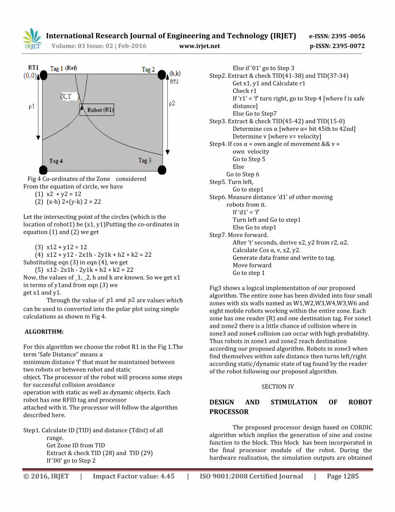
Fig 3 Platform Set-up for the proposed robot processor "→ "represents the travel route of the robot. From fig.4 we discuss about each zones Let the distances of robot R1 from reference nodes (Tags) RT1 and RT2 be _1 and _2 respectively. The distance from the static tags of its zone will be used by it to determine its location for the given distance. As in the Fig.4, we consider RT1 and RT2 as two centers of imaginary circles of radii _1 and _2 respectively. They represent the locations of active tags of a zone. R1 is on their common tangent and represents the location of reader of robot1.
International Research Journal of Engineering and Technology (IRJET) e-ISSN: 2395 -0056
Volume: 03 Issue: 02 | Feb-2016 www.irjet.net p-ISSN: 2395-0072
© 2016, IRJET | Impact Factor value: 4.45 | ISO 9001:2008 Certified Journal | Page 1285
Fig 4 Co-ordinates of the Zone considered From the equation of circle, we have
(1) x2 + y2 = 12 (2) (x-h) 2+(y-k) 2 = 22
Let the intersecting point of the circles (which is the location of robot1) be (x1, y1)Putting the co-ordinates in equation (1) and (2) we get
(3) x12 + y12 = 12 (4) x12 + y12 - 2x1h - 2y1k + h2 + k2 = 22
Substituting eqn (3) in eqn (4), we get (5) x12- 2x1h - 2y1k + h2 + k2 = 22
Now, the values of _1, _2, h and k are known. So we get x1 in terms of y1and from eqn (3) we get x1 and y1. Through the value of are values which
can be used to converted into the polar plot using simple calculations as shown in Fig 4. ALGORITHM: For this algorithm we choose the robot R1 in the Fig 1.The term ‘Safe Distance” means a minimum distance ‘f’ that must be maintained between two robots or between robot and static object. The processor of the robot will process some steps for successful collision avoidance operation with static as well as dynamic objects. Each robot has one RFID tag and processor attached with it. The processor will follow the algorithm described here. Step1. Calculate ID (TID) and distance (Tdist) of all
range. Get Zone ID from TID Extract & check TID (28) and TID (29) If '00' go to Step 2
Else if '01' go to Step 3 Step2. Extract & check TID(41-38) and TID(37-34)
Get x1, y1 and Calculate r1 Check r1 If ‘r1’ < ‘f’ turn right, go to Step 4 [where f is safe distance] Else Go to Step7
Step3. Extract & check TID(45-42) and TID(15-0) Determine cos α [where α= bit 45th to 42nd] Determine v [where v= velocity]
Step4. If cos α = own angle of movement && v = own velocity Go to Step 5 Else
Go to Step 6 Step5. Turn left,
Go to step1 Step6. Measure distance ‘d1’ of other moving robots from it.
If ‘d1’ < ‘f’ Turn left and Go to step1 Else Go to step1
Step7. Move forward. After ‘t’ seconds, derive x2, y2 from r2, α2. Calculate Cos α, v, x2, y2. Generate data frame and write to tag. Move forward Go to step 1
Fig3 shows a logical implementation of our proposed algorithm. The entire zone has been divided into four small zones with six walls named as W1,W2,W3,W4,W3,W6 and eight mobile robots working within the entire zone. Each zone has one reader (R) and one destination tag. For zone1 and zone2 there is a little chance of collision where in zone3 and zone4 collision can occur with high probability. Thus robots in zone1 and zone2 reach destination according our proposed algorithm. Robots in zone3 when find themselves within safe distance then turns left/right according static/dynamic state of tag found by the reader of the robot following our proposed algorithm. SECTION IV
DESIGN AND STIMULATION OF ROBOT
PROCESSOR
The proposed processor design based on CORDIC algorithm which implies the generation of sine and cosine function to the block. This block has been incorporated in the final processor module of the robot. During the hardware realization, the simulation outputs are obtained
International Research Journal of Engineering and Technology (IRJET) e-ISSN: 2395 -0056
Volume: 03 Issue: 02 | Feb-2016 www.irjet.net p-ISSN: 2395-0072
© 2016, IRJET | Impact Factor value: 4.45 | ISO 9001:2008 Certified Journal | Page 1286
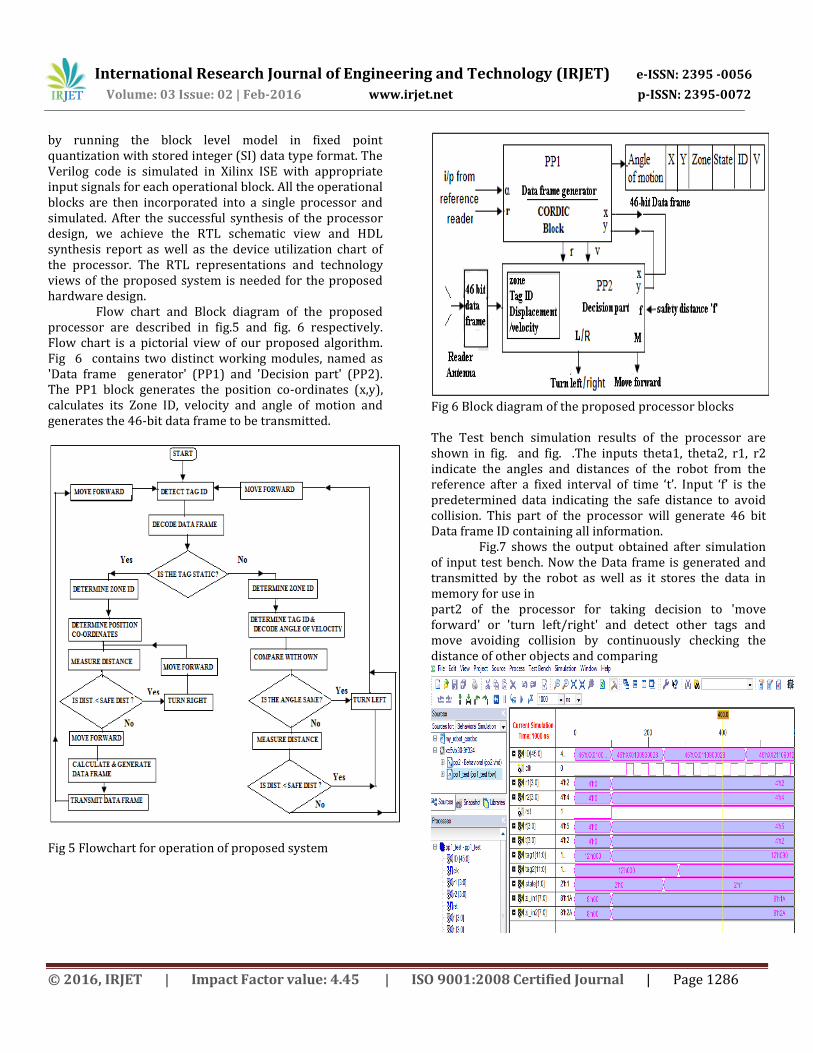
by running the block level model in fixed point quantization with stored integer (SI) data type format. The Verilog code is simulated in Xilinx ISE with appropriate input signals for each operational block. All the operational blocks are then incorporated into a single processor and simulated. After the successful synthesis of the processor design, we achieve the RTL schematic view and HDL synthesis report as well as the device utilization chart of the processor. The RTL representations and technology views of the proposed system is needed for the proposed hardware design. Flow chart and Block diagram of the proposed processor are described in fig.5 and fig. 6 respectively. Flow chart is a pictorial view of our proposed algorithm. Fig 6 contains two distinct working modules, named as 'Data frame generator' (PP1) and 'Decision part' (PP2). The PP1 block generates the position co-ordinates (x,y), calculates its Zone ID, velocity and angle of motion and generates the 46-bit data frame to be transmitted.
Fig 5 Flowchart for operation of proposed system
Fig 6 Block diagram of the proposed processor blocks
The Test bench simulation results of the processor are shown in fig. and fig. .The inputs theta1, theta2, r1, r2 indicate the angles and distances of the robot from the reference after a fixed interval of time ‘t’. Input ‘f’ is the predetermined data indicating the safe distance to avoid collision. This part of the processor will generate 46 bit Data frame ID containing all information.
Fig.7 shows the output obtained after simulation of input test bench. Now the Data frame is generated and transmitted by the robot as well as it stores the data in memory for use in part2 of the processor for taking decision to 'move forward' or 'turn left/right' and detect other tags and move avoiding collision by continuously checking the distance of other objects and comparing
International Research Journal of Engineering and Technology (IRJET) e-ISSN: 2395 -0056
Volume: 03 Issue: 02 | Feb-2016 www.irjet.net p-ISSN: 2395-0072
© 2016, IRJET | Impact Factor value: 4.45 | ISO 9001:2008 Certified Journal | Page 1287
Fig 7 Output of PP1, the Data Frame Generator
Fig 8 Output of the PP2, the Decision Part of the processor
In part2, there is an input terminal which detects 46-bit
data frame transmitted by other robots (ID2). After
decoding the frame, it identifies the zone ID, tag ID, angle
of motion,velocity etc. of the detected tag of other robot.
Now, it compares the data with its own and takes proper
decision which is required to avoid collision. Two output
terminals ‘L/R’ and ‘M’ helps for this purpose. According to
the state of these o/p bits the robot will move forward or
turn left/right.
SECTION V
RTL VIEW OF DESIGNED PROCESSOR
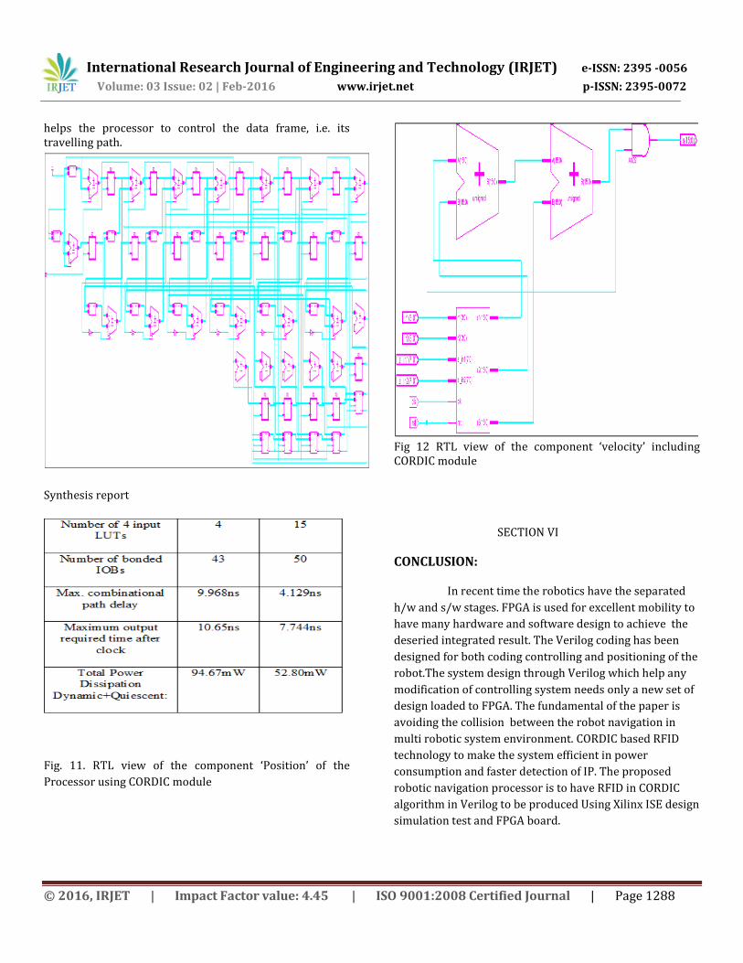
The process of detection and checking is continuous. The other cases of checking are also carried out and its result is satisfying. The RTL view of the final processor is shown infig.9. The components used in final processor and their RTL views are shown in fig.10 and fig.11. Fig. 10 is the RTL view of the 46 bit Data frame generator part of the processor. It's major components are zone detector, polar co-ordinate or position detector, velocity detector etc. The components, cos ψ and sin ψ have been achieved using
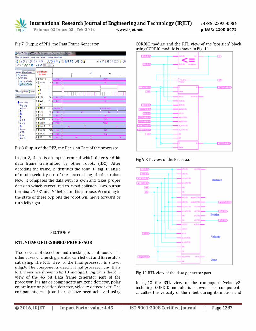
CORDIC module and the RTL view of the 'position' block using CORDIC module is shown in Fig. 11.
Fig 9 RTL view of the Processor
Fig 10 RTL view of the data generator part
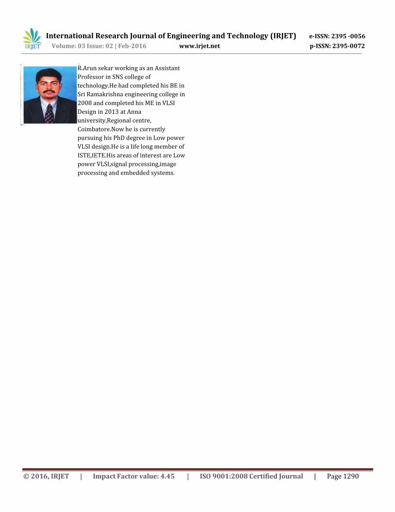
In fig.12 the RTL view of the compopent ‘velocity2’ including CORDIC module is shown. This components calcultes the velocity of the robot during its motion and
International Research Journal of Engineering and Technology (IRJET) e-ISSN: 2395 -0056
Volume: 03 Issue: 02 | Feb-2016 www.irjet.net p-ISSN: 2395-0072
© 2016, IRJET | Impact Factor value: 4.45 | ISO 9001:2008 Certified Journal | Page 1288
helps the processor to control the data frame, i.e. its travelling path.
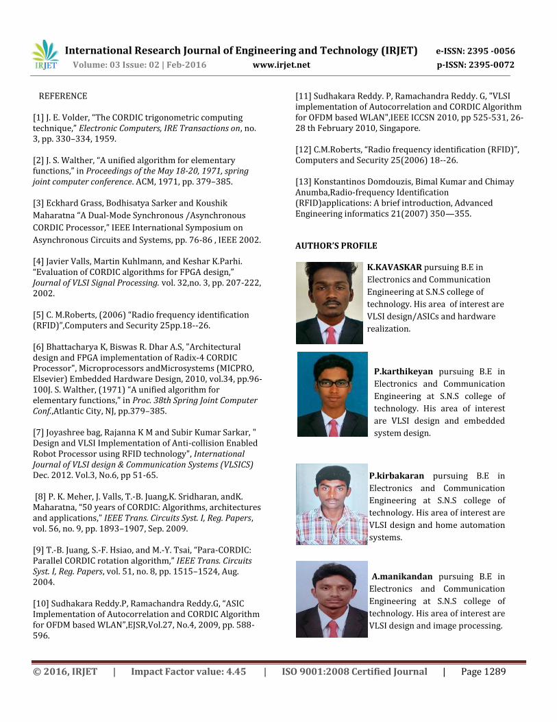
Synthesis report
Fig. 11. RTL view of the component ‘Position’ of the
Processor using CORDIC module
Fig 12 RTL view of the component ‘velocity’ including CORDIC module
SECTION VI
CONCLUSION:
In recent time the robotics have the separated
h/w and s/w stages. FPGA is used for excellent mobility to
have many hardware and software design to achieve the
deseried integrated result. The Verilog coding has been
designed for both coding controlling and positioning of the
robot.The system design through Verilog which help any
modification of controlling system needs only a new set of
design loaded to FPGA. The fundamental of the paper is
avoiding the collision between the robot navigation in
multi robotic system environment. CORDIC based RFID
technology to make the system efficient in power
consumption and faster detection of IP. The proposed
robotic navigation processor is to have RFID in CORDIC
algorithm in Verilog to be produced Using Xilinx ISE design
simulation test and FPGA board.
International Research Journal of Engineering and Technology (IRJET) e-ISSN: 2395 -0056
Volume: 03 Issue: 02 | Feb-2016 www.irjet.net p-ISSN: 2395-0072
© 2016, IRJET | Impact Factor value: 4.45 | ISO 9001:2008 Certified Journal | Page 1289
REFERENCE
[1] J. E. Volder, “The CORDIC trigonometric computing technique,” Electronic Computers, IRE Transactions on, no. 3, pp. 330–334, 1959. [2] J. S. Walther, “A unified algorithm for elementary functions,” in Proceedings of the May 18-20, 1971, spring joint computer conference. ACM, 1971, pp. 379–385. [3] Eckhard Grass, Bodhisatya Sarker and Koushik
Maharatna “A Dual-Mode Synchronous /Asynchronous
CORDIC Processor,” IEEE International Symposium on
Asynchronous Circuits and Systems, pp. 76-86 , IEEE 2002.
[4] Javier Valls, Martin Kuhlmann, and Keshar K.Parhi. “Evaluation of CORDIC algorithms for FPGA design,” Journal of VLSI Signal Processing. vol. 32,no. 3, pp. 207-222, 2002. [5] C. M.Roberts, (2006) “Radio frequency identification (RFID)”,Computers and Security 25pp.18--26. [6] Bhattacharya K, Biswas R. Dhar A.S, "Architectural design and FPGA implementation of Radix-4 CORDIC Processor", Microprocessors andMicrosystems (MICPRO, Elsevier) Embedded Hardware Design, 2010, vol.34, pp.96-100J. S. Walther, (1971) “A unified algorithm for elementary functions,” in Proc. 38th Spring Joint Computer Conf.,Atlantic City, NJ, pp.379–385. [7] Joyashree bag, Rajanna K M and Subir Kumar Sarkar, " Design and VLSI Implementation of Anti-collision Enabled Robot Processor using RFID technology", International Journal of VLSI design & Communication Systems (VLSICS) Dec. 2012. Vol.3, No.6, pp 51-65. [8] P. K. Meher, J. Valls, T.-B. Juang,K. Sridharan, andK. Maharatna, “50 years of CORDIC: Algorithms, architectures and applications,” IEEE Trans. Circuits Syst. I, Reg. Papers, vol. 56, no. 9, pp. 1893–1907, Sep. 2009. [9] T.-B. Juang, S.-F. Hsiao, and M.-Y. Tsai, “Para-CORDIC: Parallel CORDIC rotation algorithm,” IEEE Trans. Circuits Syst. I, Reg. Papers, vol. 51, no. 8, pp. 1515–1524, Aug. 2004. [10] Sudhakara Reddy.P, Ramachandra Reddy.G, “ASIC Implementation of Autocorrelation and CORDIC Algorithm for OFDM based WLAN”,EJSR,Vol.27, No.4, 2009, pp. 588-596.
[11] Sudhakara Reddy. P, Ramachandra Reddy. G, "VLSI implementation of Autocorrelation and CORDIC Algorithm for OFDM based WLAN",IEEE ICCSN 2010, pp 525-531, 26-28 th February 2010, Singapore. [12] C.M.Roberts, “Radio frequency identification (RFID)”, Computers and Security 25(2006) 18--26. [13] Konstantinos Domdouzis, Bimal Kumar and Chimay Anumba,Radio-frequency Identification (RFID)applications: A brief introduction, Advanced Engineering informatics 21(2007) 350—355.
AUTHOR’S PROFILE
K.KAVASKAR pursuing B.E in
Electronics and Communication
Engineering at S.N.S college of
technology. His area of interest are
VLSI design/ASICs and hardware
realization.
P.karthikeyan pursuing B.E in
Electronics and Communication
Engineering at S.N.S college of
technology. His area of interest
are VLSI design and embedded
system design.
P.kirbakaran pursuing B.E in
Electronics and Communication
Engineering at S.N.S college of
technology. His area of interest are
VLSI design and home automation
systems.
A.manikandan pursuing B.E in
Electronics and Communication
Engineering at S.N.S college of
technology. His area of interest are
VLSI design and image processing.
International Research Journal of Engineering and Technology (IRJET) e-ISSN: 2395 -0056
Volume: 03 Issue: 02 | Feb-2016 www.irjet.net p-ISSN: 2395-0072
© 2016, IRJET | Impact Factor value: 4.45 | ISO 9001:2008 Certified Journal | Page 1290
R.Arun sekar working as an Assistant
Professor in SNS college of
technology.He had completed his BE in
Sri Ramakrishna engineering college in
2008 and completed his ME in VLSI
Design in 2013 at Anna
university,Regional centre,
Coimbatore.Now he is currently
pursuing his PhD degree in Low power
VLSI design.He is a life long member of
ISTE,IETE.His areas of interest are Low
power VLSI,signal processing,image
processing and embedded systems.