vjer-vishwakarma journal of engineering research … · vjer-vishwakarma journal of engineering...
TRANSCRIPT

VJER-Vishwakarma Journal of Engineering Research www.vjer.in Volume 1 Issue 2, June 2017 ISSN: 2456-8465
144
A STUDY OF COMPARISON OF STEEL SILOS UNDER INFLUENCE OF DYNAMIC LOADING IN ACCORDANCE WITH IS-1893:2002
Pradnya P.Dhamdhere1 Y.R.Suryawanshi2
Post Graduate Student, Civil Engineering Department Assistant Professor, Civil Engineering DepartmentJSPM’s Imperial College of Engineering JSPM’s Imperial College of Engineering
& Research, Wagholi, Pune. & Research, Wagholi, Pune.Email [email protected] Email [email protected]
ABSTRACT
Silos are containers used for storing bulk solids. Although there is no generally accepted definition for these terms, shallow structures containing coal, coke, ore, crushed stone, gravel, and similar materials. Silos are special structures subjected to many different unconventional loading conditions, which result in unusual failure modes. In this present study pressure calculation is carried out by Janseen’s theory and Reimbert theory for static condition and additional pressure due seismic action is calculated by Theoretical approach. Base shear force generated at bottom of silo is compared with using IS 1893-2002, ASCE 7-05, AIJ 2010. Calculation is completely based on respective codal provision applied to Indian seismic zones, site condition etc.
Keywords: Silo, silo failure, action of forces, seismic behavior.
INTRODUCTION
Theory of silo 1. Silo: - A storage structure, circular or polygonal in plan & intended for storing bulk material in vertical direction. The line of rupture start from bottom edge of bins intersects the wall it is called silo.
2. Bunker: - The line of rupture start from bottom edge of bins intersects the top surface of the material it is called Bunker or shallow bunker.
3. Bins: - Bins is common name for bunker & silos.
4. Silo Loads: - Loads exerted by a stored material on the wall of silo.
5. Pressure: - Force per unit area normal to wall of silo.
6. Initial pressure: - Pressure exerted by bulk solids on the walls of the silo during & after charging, but before any withdrawal of the material.
7. Strain energy: - The energy of a flowing mass of solid which could be recovered by a relaxation of boundary forces & displacement

VJER-Vishwakarma Journal of Engineering Research www.vjer.in Volume 1 Issue 2, June 2017 ISSN: 2456-8465
145
8. Wall friction: - Force per unit area along the silo wall (vertical or inclined) on account of friction between the bulk material and the silo wall.
9. Flat bottom: - The internal base of silo, when it has an inclination to the horizontal less than 5 degree.
10. Horizontal load ratio K: - A value which specifies the relationship between the mean horizontal load acting on the vertical silo walls, and the mean vertical load at this position in the bulk material.
11. Bulk material: - A term used to describe a granular material ranging from a dust-like to a large-grained variety with and without cohesion, which contains pores in addition to and in-between the individual solid material particles that may be filled with air or moisture.
Types of Silo
1 Flat Bottom Silos
2 Hopper Silos
3 Truck load silos
Load consider for Silo Design
Loads should be applied to the structural design of a silo according to its intended use, size, structure type, materials, design lifetime, location and environment, in order to assure life safety and to maintain its essential functions.
The applied loads should be as follows, and their combinations should be defined considering the actual probability of occurrence.
(i) Dead loads
(ii) Live loads
(iii) Snow loads
(iv) Wind loads
(v) Seismic loads
(vi) Impulse and suction due to content sloshing, and pressure due to content
(vii) Thermal stresses
(viii) Shock, e. g., by crane
(ix) Fatigue loads
VJER-Vishwakarma Journal of Engineering Research www.vjer.in Volume 1 Issue 2, June 2017 ISSN: 2456-8465
146
(x) Soil and water pressures
(xi) Others. e.g., load from mechanical device.
Silo Damage and FailuresSilos structure failure frequency higher than other industrial structures. When a silo fails it can be devastating, in more ways than one including: loss of the container, contamination of the material it contains, loss of material, clean-up, replacement costs, and most importantly possible injury or loss of life.
1. Filling and Discharging2. Soil Condition3. Corrosion4. Internal Structure Collapse5. Deterioration6. Thermal Ratcheting7. Earthquakes
Actions on silo1. Temperature variation2. Consolidation3. Moisture Content4. Segregation5. Degradation6. Impact Pressures7. Rapid Filling and Discharge8. Powders9. Wind Loading10. Dust Explosions11. Differential Settlements12. Mechanical Discharge Equipment13. Roof Loads
The design of silo is based on the strength design method. The design of silos is primarily governed by the type and properties of the stored material. The walls of the silos are typically subjected to both normal pressure and vertical frictional shear or traction produced by the material stored inside the silo. The magnitude and distribution of both shear and normal pressure over the height of the wall depend on the properties of the stored material and whether the silo is being filled or discharged. Design of silo considers both static & dynamic condition. Static & dynamic pressure exerted by the stored material. Other potential loads, including seismic loads, calculation of seismic load consider silo self weight and material
VJER-Vishwakarma Journal of Engineering Research www.vjer.in Volume 1 Issue 2, June 2017 ISSN: 2456-8465
147
stored in it as a lumped mass and seismic effect of this mass is considered in design of the silo wall. Storage container & silo fails because of many reason. Failure of silo categories depend on silo failure causes which are as follows,
Failure due to design Failure due to construction Failure due to usage Failure due to maintenance
Collapse of silo in seismic failure is the major failure; occur because of improper assumptions, wrong analysis and design. In this study consider circular flat bottom silo symmetrical about vertical axis & RCC slab provided at the top and bottom of silo by proving small open able hole to top of silo for filling storage material in it. In this study compare various method of silo design and seismic force calculation by using different codal provision like IS, ASCE, AJI, and EURO. The walls of the silos are typically subjected to both normal pressure and vertical frictional shear or traction produced by the material stored inside the silo. The magnitude and distribution of both shear and normal pressure over the height of the wall depend on the properties of the stored material. Calculation of seismic load consider silo self-weight and material stored in it as a lumped mass and seismic effect of this mass is considered in design of the silo wall.
An earthquake analysis effective components acting on silo due to structural loading are the two horizontal and one vertical direction. Silos have effect of seismic vertical loads is small, compare to lateral seismic loads on the tall silos storing heavy material. Seismic load magnitude in lateral direction directly related to the weight of silo. In earthquake analysis increase of lateral load bending moment also increases result of this non uniform pressure at bottom of silo increase as compare to pressure due gravity load.
VJER-Vishwakarma Journal of Engineering Research www.vjer.in Volume 1 Issue 2, June 2017 ISSN: 2456-8465
148
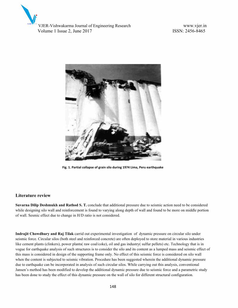
Fig. 1. Partial collapse of grain silo during 1974 Lima, Peru earthquake
Literature review
Suvarna Dilip Deshmukh and Rathod S. T. conclude that additional pressure due to seismic action need to be considered while designing silo wall and reinforcement is found to varying along depth of wall and found to be more on middle portion of wall. Sesmic effect due to change in H/D ratio is not considered.
Indrajit Chowdhury and Raj Tilak carrid out experimental investigation of dynamic pressure on circular silo under seismic force. Circular silos (both steel and reinforced concrete) are often deployed to store material in various industries like cement plants (clinkers), power plants( raw coal/coke), oil and gas industry( sulfur pellets) etc. Technology that is in vogue for earthquake analysis of such structures is to consider the silo and its content as a lumped mass and seismic effect of this mass is considered in design of the supporting frame only. No effect of this seismic force is considered on silo wall when the content is subjected to seismic vibration. Procedure has been suggested wherein the additional dynamic pressure due to earthquake can be incorporated in analysis of such circular silos. While carrying out this analysis, conventional Jansen’s method has been modified to develop the additional dynamic pressure due to seismic force and a parametric study has been done to study the effect of this dynamic pressure on the wall of silo for different structural configuration.
VJER-Vishwakarma Journal of Engineering Research www.vjer.in Volume 1 Issue 2, June 2017 ISSN: 2456-8465
149
Structural committee of Japan gives seismic design calculations for other types of storage tanks. Design recommendation for sloshing phenomena in tanks has been added. Design spectra for sloshing, spectra for long period range in other words, damping ratios for the sloshing phenomena and pressures by the sloshing on the tank roof have been presented. In this study consider storage cylindrical tanks resting on ground without having any restrain to prevent overturning moment such as anchor bolt. This recommendation shows how to evaluate the energy absorption value given by plasticity of the uplifted bottom plate for unanchored tanks. As the number of smaller under-ground tanks used for the storage of water and fuel is increasing in Japan, the Sub-committee has added them in the scope of the recommendation and provided a framework for the seismic design of under-ground tanks. The recommendation has accordingly included a new response displacement method and a new earth pressure calculation method, taking into account the design methods adopted by the civil engineering fraternity. For silo design, additional local pressure which depends on eccentricity of discharge outlet, and equations which give approximate stress produced by this pressure are given in this 2010 publication.
Aim and Objective
A study of comparison of steel silos under influence of dynamic loading in accordance with is 1893:2002
To achieve aim of the project study based on the following objective,
1. To analyze single and double hopper steel silos for different soil condition in accordance with IS:1893-2002
2. To check performance of steel silos in variation with H/D ratio, Pressure calculation values obtain from the equation is check with pressure calculated by using Janseen theory and Reimbert Theory.
Design of silo
Silos and their supports should be designed to contain all applicable loads taking into account the properties of stored materials, the shape of the silos, methods of material handling. The shape of the silo should be as simple as possible, be symmetrical about its axis, and should have structural members which are proportioned to provide adequate strength. Physical property tests using actual granular materials are expected to find weight per unit volume, internal friction angle; and deformation characteristics. In silos the weight of material stored is supported by bottom of silo and side wall of silo resulting reduction in lateral pressure. Vertical weight carried by wall causes direct compression in wall.

VJER-Vishwakarma Journal of Engineering Research www.vjer.in Volume 1 Issue 2, June 2017 ISSN: 2456-8465
150
Fig.2 Plan of silo showing horizontal pressure acting on the silo wall
Fig.3.Elevation of silo showing vertical pressure acting on silo wall
Theories for pressure calculation
Many researchers have provided theories for pressure calculation on silo wall. Some of the theory used are:
Janssen Theory Reimbert Theory
Finite element analysis of silo
For calculation of static pressure on silo wall parameter consider for silo design as per IS code. While calculation done for seismic force parameter used for calculation of seismic force will varies with their respective code condition that parameter.
VJER-Vishwakarma Journal of Engineering Research www.vjer.in Volume 1 Issue 2, June 2017 ISSN: 2456-8465
151
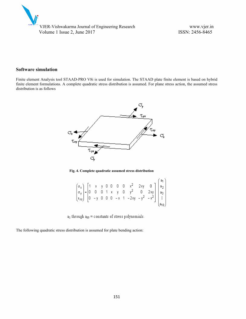
Software simulation
Finite element Analysis tool STAAD-PRO V8i is used for simulation. The STAAD plate finite element is based on hybrid finite element formulations. A complete quadratic stress distribution is assumed. For plane stress action, the assumed stress distribution is as follows
Fig. 4. Complete quadratic assumed stress distribution
The following quadratic stress distribution is assumed for plate bending action:

VJER-Vishwakarma Journal of Engineering Research www.vjer.in Volume 1 Issue 2, June 2017 ISSN: 2456-8465
152
Fig. 5. Complete quadratic assumed stress distribution
Following are the items included in the ELEMENT STRESS output.SQX, SQY -Shear stresses (Force/ unit len./ thk.) Sx, Sy, Sxy -Membrane stresses (Force/unit len./ thk) Mx, My, Mxy- Moments per unit width (Force x Length/length) (For Mx, the unit width is a unit distance parallel to the local Y axis. For My, the unit width is a unit distance parallel to the local X axis. Mx and My cause bending, while Mxy causes the element to twist out-of-plane.) Smax, Smin Principal stresses in the plane of the element (Force/unit area) TMAX Maximum shear stress in the plane of the element (Force/unit area) ANGLE Orientation of the principal plane (Degrees) VONT, VONB Von Mises stress, where

VJER-Vishwakarma Journal of Engineering Research www.vjer.in Volume 1 Issue 2, June 2017 ISSN: 2456-8465
153
Fig. 6. Sign Convention of Plate Element Stresses and Moments
Problem statements
In this paper steel single hopper silos and double hopper silo is analyzed using STAAD-PRO V8i.
Self weight
DL=Volume*Density =25*.02*3*3=4.5 KN/m2
Load on vertical walls
Ph=𝛾h𝑘 =25*3*0.4 =30KN/m2
Where k is 0.25 ≤k≤ 0.6(Ref. Janssen theory)
Earthquake load
Zone-IIIZone factor-0.16Soil Condition-MediumTime Period-Ta=0.09h/ =0.5sec√𝑑Sa/g-2.5Damping Ratio=0.05

VJER-Vishwakarma Journal of Engineering Research www.vjer.in Volume 1 Issue 2, June 2017 ISSN: 2456-8465
154
Table 2 Problem statement
Purpose of silo Storage of cement Storage of cementType Steel silo Steel siloConfiguration A single free standing
rectangular shapeDouble free standing rectangular shape
Height of silo 12m 12mlength 3m 1.5mwidth 3m 1.5mThickness of silo 20mm 20mmStorage product density 15.50kN/m3 15.50kN/m3
Angle of internal friction 25 25Friction coefficient of tank wall 0.46 0.46coefficient of wall friction(ȝ) tanф tanфSeismic zone III IIIGrade of Steel Fe500 Fe500
RESULTS AND DISCUSSION
In this paper single steel silos of 3x3 m is compared with double hopper steel silos of 1.5x1.5m maintaining same areas.
Fig 7. Shear stress develop at corners of double hopper silos

VJER-Vishwakarma Journal of Engineering Research www.vjer.in Volume 1 Issue 2, June 2017 ISSN: 2456-8465
155
Fig. 8. Shear stress develop at edge of single hopper silos
Fig. 9. Deflection of double hopper silos
VJER-Vishwakarma Journal of Engineering Research www.vjer.in Volume 1 Issue 2, June 2017 ISSN: 2456-8465
156
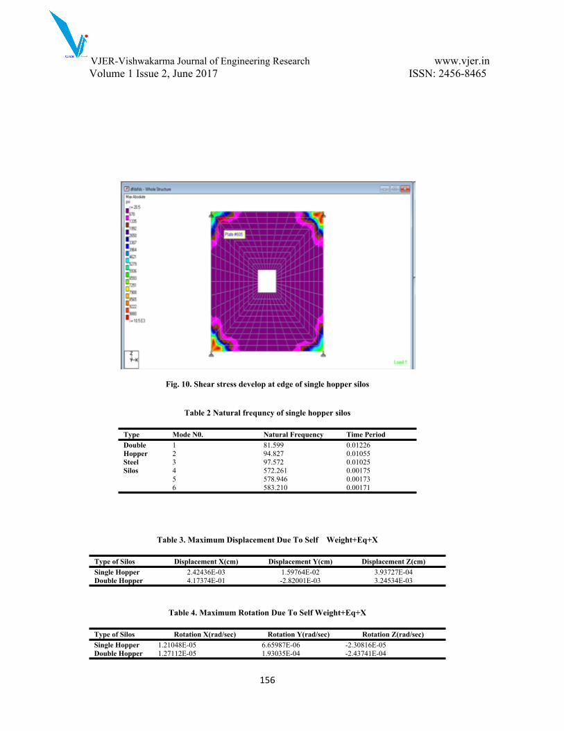
Fig. 10. Shear stress develop at edge of single hopper silos
Table 2 Natural frequncy of single hopper silos
Type Mode N0. Natural Frequency Time Period1 81.599 0.012262 94.827 0.010553 97.572 0.010254 572.261 0.001755 578.946 0.00173
Double Hopper Steel Silos
6 583.210 0.00171
Table 3. Maximum Displacement Due To Self Weight+Eq+X
Type of Silos Displacement X(cm) Displacement Y(cm) Displacement Z(cm)Single Hopper 2.42436E-03 1.59764E-02 3.93727E-04Double Hopper 4.17374E-01 -2.82001E-03 3.24534E-03
Table 4. Maximum Rotation Due To Self Weight+Eq+X
Type of Silos Rotation X(rad/sec) Rotation Y(rad/sec) Rotation Z(rad/sec)Single Hopper 1.21048E-05 6.65987E-06 -2.30816E-05Double Hopper 1.27112E-05 1.93035E-04 -2.43741E-04

VJER-Vishwakarma Journal of Engineering Research www.vjer.in Volume 1 Issue 2, June 2017 ISSN: 2456-8465
157
Conclusion
In this study single and double hopper steel silos is analyzed under the influence of self weight, pressure on vertical wall and seismic load. It was observe that maximum displacement along X-direction and Z-direction is comparatively less in single hopper silo. But displacement along in Y-direction i.e. along gravity direction is comparatively less in double hopper silo. However nodal rotation are remain nearly same indicates that the torsion movement due to accidental eccentricity will be same in both cases. Natural frequency for first three modes is considerably less and hence time period is more for double hopper steel silo.Future scope
1) H/D ratio of all types of silos need to be studied this result can be used in IS: 9178 part II 20062) Comparison should be made under various type of eccentricity hopper bottom for various soil conditions.
REFERENCES
1) Architectural Institute of Japan, Design recommendation for storage tanks and their supports with emphasis on seismic design (2010 edition ASCE 7-05 Minimum design loads for Buildings )
2) Chowdhury I -2009. Dynamic response of reinforced concrete rectangular bunkers under earthquake force. The Indian Concrete Journal Vol-83 #2 pp 7-18.
3) Comparison of Design & Seismic Behavior of RCC SILO Suvarna Dilip Deshmukh1, Rathod S. T.2
4) Hamdan, F.H. 2000. Seismic behaviour of cylindrical steel liquid storage tanks, “Journal of Constructional Steel Research”, Vol. 53, p. 307 V333.
5) Indrajit Chowdhury 1 and Raj Tilak2. Dynamic pressure on circular silos under seismic force, 14th Symposium on Earthquake Engineering Indian Institute of Technology, Roorkee December 17-19, 2010.
6) IS 4995 (Part 1) V 1974. Criteria for design of reinforced concrete bins for the storage of granular & powdery material.
7) IS 4995 (Part 2) V 1974. Criteria for design of reinforced concrete bins for the storage of granular & powdery material.
8) IS-1893-2002 Indian Standard Code of practice for earthquake resistant design of structures Bureau of Indian Standards New Delhi.
9) Nateghi F. and M. Yakhchalian. “seismic behaviour of silos with different height to diameter ratios considering granular material structure interaction”, December 15, 2011.
10) Salmon and Jonhson, “Design of steel structure 2” CBS Publisher (5th edition).
VJER-Vishwakarma Journal of Engineering Research www.vjer.in Volume 1 Issue 2, June 2017 ISSN: 2456-8465
158
11) Silvestri1 S., T. Trombetti2 and G. Gasparini, “Flat-bottom grain silos under earthquake ground motion”, The 14thWorld Conference on Earthquake Engineering October 12-17, 2008, Beijing, China
12) Standard Practice for Design and Construction of Concrete Silos and Stacking Tubes for Storing Granular Materials (ACI 313-97).