vision engravers and routers installation · pdf filevision engravers and routers installation...
TRANSCRIPT

© 2015 Vision Engraving & Routing Systems
Revised: 8/19/2015
Vision Engravers andRouters
Installation Guide
Factory Settings
Red Dot Laser Pointer OffsetX__________ Inches__ mm__Y__________ Inches__ mm__
Braille Inserter OffsetX__________ Inches__ mm__Y__________ Inches__ mm__
This is ONLY the Installation Guide.PLEASE review the complete User Manualfor your machine, which will be installed onyour computer after the softwareinstallation is completed.
PN: 12-1074-00

All rights reserved. No parts of this work may be reproduced in any form or by any means - graphic, electronic, ormechanical, including photocopying, recording, taping, or information storage and retrieval systems - without the writtenpermission of the publisher.
Products that are referred to in this document may be either trademarks and/or registered trademarks of the respectiveowners. The publisher and the author make no claim to these trademarks.
While every precaution has been taken in the preparation of this document, the publisher and the author assume noresponsibility for errors or omissions, or for damages resulting from the use of information contained in this document orfrom the use of programs and source code that may accompany it. In no event shall the publisher and the author be liablefor any loss of profit or any other commercial damage caused or alleged to have been caused directly or indirectly by thisdocument.
Revised: 8/19/2015
Vision Engravers and Routers InstallationGuide© 2015 Vision Engraving & Routing Systems

3Contents
3
© 2015 Vision Engraving & Routing Systems
Table of Contents
Part I Introduction 5
................................................................................................................................... 71 Computer Requirements
................................................................................................................................... 82 Direct Connection to Computer
................................................................................................................................... 153 Network Connection
................................................................................................................................... 184 Using a Router or Hub - ONLY
................................................................................................................................... 255 Vision Software Installation
Part II General Electrical and Facility Requirementsby Model 35
Part III Pendant Holder Installation 36
Part IV Express and VE-810 40
................................................................................................................................... 411 Express Layout Diagram
................................................................................................................................... 412 VE-810 Layout Diagram
Part V Phoenix 1212 42
................................................................................................................................... 431 Phoenix 1212 Layout Diagram
Part VI 16 Series and 24 Series Engravers 44
................................................................................................................................... 451 1612 and 1624 Engraver Layout Diagram
................................................................................................................................... 462 2424 and 2448 Engraver Layout Diagram
Part VII 16 Series and 25 Series Routers 47
................................................................................................................................... 471 High Frequency Router Head
................................................................................................................................... 512 Engraving Head
................................................................................................................................... 533 1624R Router Layout Diagram
................................................................................................................................... 544 2525 and 2550 Router Layout Diagrams
Part VIII MAX and MAX PRO 57
................................................................................................................................... 581 MAX and MAX PRO Layout Diagram
Part IX VR48 Router 59
................................................................................................................................... 591 Requirements
................................................................................................................................... 622 Wiring Connections
................................................................................................................................... 663 Vacuum Pump Connections - Vacuum Table Models Only
................................................................................................................................... 674 VR48 Router Layout Diagrams

Vision Engravers and Routers Installation Guide4
© 2015 Vision Engraving & Routing Systems

Introduction 5
© 2015 Vision Engraving & Routing Systems
1 Introduction
This guide contains information to prepare the new owner of a Vision Engraver or Router forthe proper installation of their machine. It is the customer's responsibility to read through thisguide and make sure the work area, electrical and computer requirements are met prior to thearrival of a representative from Vision for the scheduled installation/machine orientation date(Training NOT included with Vision Express machines). If for any reason, there are questionsabout these requirements, please call your Vision representative as soon as possible.IMPORTANT – Once your training day is scheduled, if for any reason you have to canceltraining or change the dates, you may be subject to fees associated with your change request. However, if the trainer arrives at your facility on the day of training and you have to cancel orreschedule training at that time, a fee of $750 will be required before Vision will send the trainerback to your facility in addition to fees associated with your change request. No exceptions.
In the following sections, the complete machine and Vision software installation will be outlined.There are three connection configurations possible with the Vision Engraver or Router.
The first is a direct cable connection to your computer via the network port. There is a special"crossover" cable (the cable colored gray) supplied for this connection type. This configurationis for a stand alone computer that is NOT connected to a WIRED network or internet. Aconnection can be made to a computer that is connected to a wireless network in this manner.
The second configuration is for connection through a wired network using a standard Ethernetcable (DO NOT use the crossover cable when connecting to a network). In this configuration,the engraver or router will be recognized as a network device. Connection in this manner is theeasier of the two connection types. If there are no network connections available, a networkhub can be added to allow connection to your network.
The third configuration is for a connection from the computer to a hub (or router) and then toyour machine. This is WITHOUT a computer network. Standard Ethernet cables are used inthis configuration.
Please call your distributor or the service department at Vision for assistance if you are havingproblems with this procedure.
FOR MORE DETAILED INFORMATION, PLEASE REFER TO THE USER GUIDE FOR YOUR
MACHINE INSTALLED WITH THE VISION SOFTWARE. USER GUIDES ARE ALSO
AVAILABLE ONLINE AT http://www.visionengravers.com/support/vision-engraver-manuals.html

Vision Engravers and Routers Installation Guide6
© 2015 Vision Engraving & Routing Systems
To begin installation, locate the White/Blue Dongle or OrangeDongle or USB Stick included with your machine in theAccessories Box
Important Note:
The Vision software is available in two versions; one with a dongle, and onethat is "dongle-less" and is loaded on to a USB Memory stick.
If your machine was delivered with, or you currently have the white/blue ororange software dongle, DO NOT LOSE IT!
The Vision software will NOT run without the dongle plugged into thecomputer.

Introduction 7
© 2015 Vision Engraving & Routing Systems
1.1 Computer Requirements
IT IS HIGHLY RECOMMENDED THAT THE COMPUTER USED TO OPERATE THE VISIONENGRAVER OR ROUTER BE CONNECTED TO THE INTERNET. THIS ALLOWS THE USER TOALLOW VISION'S TECHNICAL SUPPORT TO ACCESS THE MACHINE AND TROUBLESHOOT IFNECESSARY.
Minimum SystemRequirements
CPU: Dual Core (2.0GHz or higher)
Hard Drive: 500 GB free space
RAM: 1GB + OS Requirements
Operating System: Windows 10 - 32 Bit & 64 Bit
Windows 8 & 8.1 - 32 Bit & 64 Bit
Windows 7 - 32 Bit & 64 Bit
Windows XP SP3 - 32 Bit (64 Bit not supported)
Ports: USB port for security dongle
Local or network Ethernet port to connect machine
Suggested SystemRequirements
CPU: Core i3 (or faster)
Hard Drive: 1 TB (or more)
RAM: 4GB + OS Requirements
Operating System: Windows 10 - 32 Bit & 64 Bit
Windows 8 & 8.1 - 32 Bit & 64 Bit
Windows 7 - 32 Bit & 64 Bit
Ports: USB port for security dongle
Local or network Ethernet port to connect machine

Vision Engravers and Routers Installation Guide8
© 2015 Vision Engraving & Routing Systems
1.2 Direct Connection to Computer
Direct Connection to Computer Using Crossover Cable
Once the machine or controller is connected directly to your computer's network port with thecrossover cable (the gray colored cable), turn the machine or controller on. The power switch for theVision Express is located on the power supply box for the machine. The power switch for the VE810 islocated below the LCD screen on the front of the machine. The power switch for the Vision Series 4Controller is located on the front left of the Controller. Once the machine or controller has initialized,plug the supplied Vision USB drive (or orange USB Dongle) into an available USB port on yourcomputer.
NOTE - This installation is performed on a Windows 7 PC. For Windows XP, Windows 8, Windows 8.1or Windows 10, the screens are slightly different.
The computer will recognize the USB drive and the following screen will appear. Select Continue without scanning.
Select Open folder to view files.

Introduction 9
© 2015 Vision Engraving & Routing Systems
Locate the file named Start and double click on the file to start the installation. The screen below showsStart.exe, but your computer might not show the .exe portion.
Select Step 1 - Setup Machine. This installs the Vision Connectivity Manager software.
Vision Engravers and Routers Installation Guide10
© 2015 Vision Engraving & Routing Systems
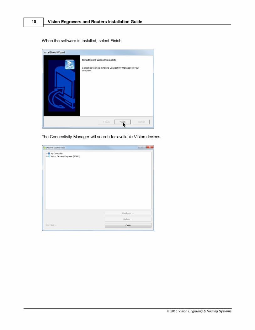
When the software is installed, select Finish.
The Connectivity Manager will search for available Vision devices.

Introduction 11
© 2015 Vision Engraving & Routing Systems
The computer's IP address will need to be set. NOTE - this should not cause any conflicts with yourcomputer's wireless IP address, which is determined by the computer's wireless network card. To setthe computer's IP address, open the Window's Control Panel. Depending on how you have this folderset, you will either see Network and Internet, or you will see the Network and Sharing Centerimmediately. If you see Network and Internet, select View Network Status and Tasks (which opens theNetwork and Sharing Center). If you see the Network and Sharing Center, open it. Then select LocalArea Connection (as shown below).
Select Properties.

Vision Engravers and Routers Installation Guide12
© 2015 Vision Engraving & Routing Systems
Then, select Internet Protocol Version 4 (TCP/IPv4).
Then select Properties. Select Use the following IP address: and enter 192.168.5.100 and set theSubnet mask to 255.255.255.0 as shown. Then select OK and close any other network configurationwindows.

Introduction 13
© 2015 Vision Engraving & Routing Systems
The IP address of the machine will need to be set to set up the connections properly. Select the + boxnext to the machine now listed in the Discover Machine Tools window to expand the information. Thenselect Configure (Your Machine) at the bottom of the screen.
Select Use Static IP.

Vision Engravers and Routers Installation Guide14
© 2015 Vision Engraving & Routing Systems
Set the IP address (as shown) to 192.168.5.101, then select OK. This sets the machine's IP address.
The configuration is complete at this point. Close the Discover Machine Tools window and return to theMain Installation Screen to proceed with the Vision software installation in the next section.

Introduction 15
© 2015 Vision Engraving & Routing Systems
1.3 Network Connection
Connecting via Standard Network Cable to Network
Once the machine or controller is connected to your network, turn the machine or controller on. Thepower switch for the Vision Express is located on the power supply box for the machine. The powerswitch for the VE810 is located below the LCD screen on the front of the machine. The power switchfor the Vision Series 4 Controller is located on the front left side of the controller. Once the machine orcontroller has initialized, plug the supplied Vision USB drive (or orange USB Dongle) into an availableUSB port on your computer.
NOTE - This installation is performed on a Windows 7 PC. For Windows XP, Windows 8, Windows 8.1or Windows 10, the screens are slightly different.
The computer will recognize the USB drive and the following screen will appear. Select Continue without scanning.
Select Open folder to view files.
Vision Engravers and Routers Installation Guide16
© 2015 Vision Engraving & Routing Systems
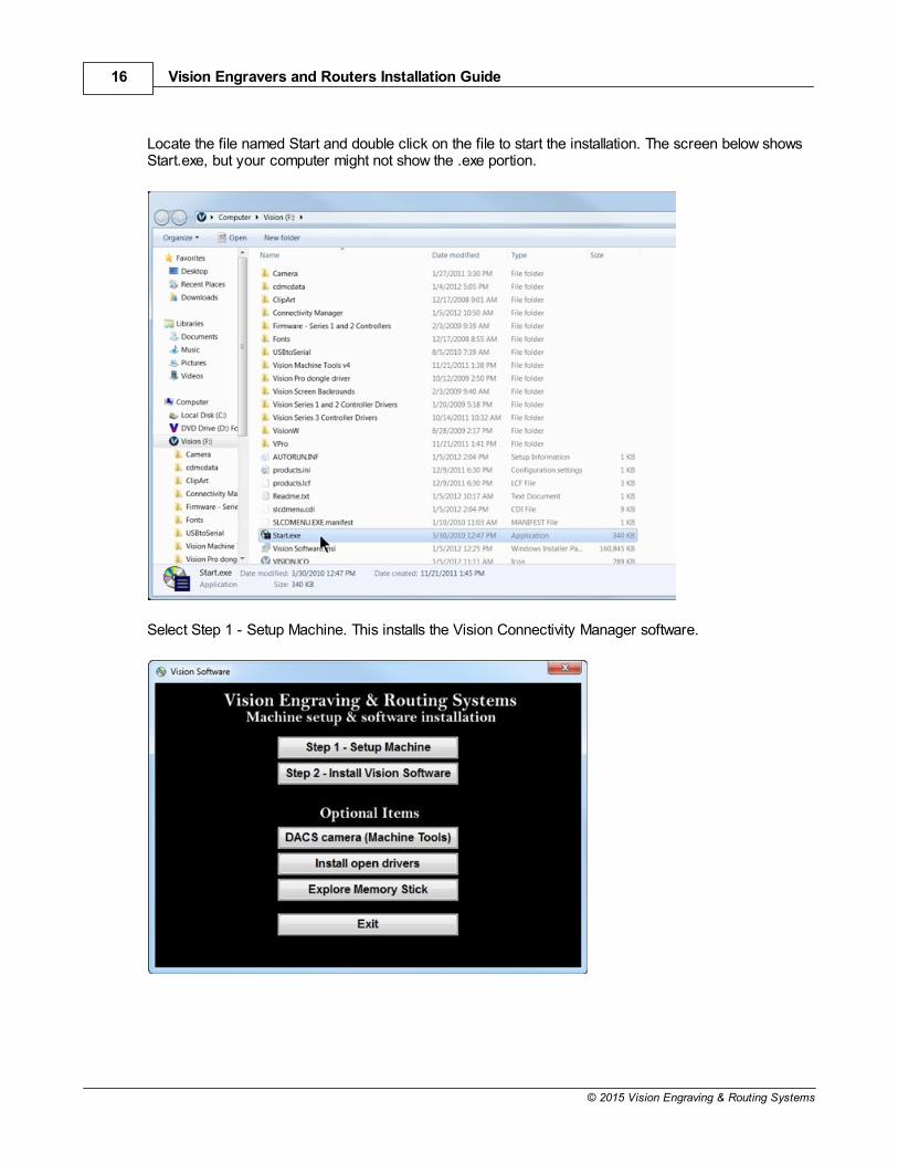
Locate the file named Start and double click on the file to start the installation. The screen below showsStart.exe, but your computer might not show the .exe portion.
Select Step 1 - Setup Machine. This installs the Vision Connectivity Manager software.

Introduction 17
© 2015 Vision Engraving & Routing Systems
When the software is installed, select Finish.
The Connectivity Manager will search for available Vision devices.
The configuration is complete at this point. Close the Machine Tools Discovery window and return tothe Main Installation Screen to proceed with the Vision software installation in the next section.

Vision Engravers and Routers Installation Guide18
© 2015 Vision Engraving & Routing Systems
1.4 Using a Router or Hub - ONLY
Connection from PC to Hub or Router to Machine or Controller
Once the machine is connected to a hub or router, and the hub or router is connected to yourcomputer's network port, turn the machine or controller on. The power switch for the Vision Express islocated on the power supply box for the machine. The power switch for the VE810 is located below theLCD screen on the front of the machine. The power switch for the Vision Series 4 Controller is locatedon the front left of the Controller. Once the machine or controller has initialized, plug the suppliedVision USB drive (or orange USB Dongle) into an available USB port on your computer.
NOTE - This installation is performed on a Windows 7 PC. For Windows XP, Windows 8, Windows 8.1or Windows 10, the screens are slightly different.
The computer will recognize the USB drive and the following screen will appear. Select Continue without scanning.
Select Open folder to view files.

Introduction 19
© 2015 Vision Engraving & Routing Systems
Locate the file named Start and double click on the file to start the installation. The screen below showsStart.exe, but your computer might not show the .exe portion.
Select Step 1 - Setup Machine. This installs the Vision Connectivity Manager software.

Vision Engravers and Routers Installation Guide20
© 2015 Vision Engraving & Routing Systems
When the software is installed, select Finish.
The Connectivity Manager will search for available Vision devices.

Introduction 21
© 2015 Vision Engraving & Routing Systems
The computer's IP address will need to be set. To set the computer's IP address, open the Window'sControl Panel. Depending on how you have this folder set, you will either see Network and Internet, oryou will see the Network and Sharing Center immediately. If you see Network and Internet, select ViewNetwork Status and Tasks (which opens the Network and Sharing Center). If you see the Network andSharing Center, open it. Then select Local Area Connection (as shown below).
Select Properties.

Vision Engravers and Routers Installation Guide22
© 2015 Vision Engraving & Routing Systems
Then, select Internet Protocol Version 4 (TCP/IPv4).
Then select Properties. Select Use the following IP address: and enter 192.168.5.100 and set theSubnet mask to 255.255.255.0 as shown. Then select OK and close any other network configurationwindows.

Introduction 23
© 2015 Vision Engraving & Routing Systems
The IP address of the machine will need to be set to set up the connections properly. Select the + boxnext to the machine now listed in the Discover Machine Tools window to expand the information. Thenselect Configure (Your Machine) at the bottom of the screen.
Select Use Static IP.

Vision Engravers and Routers Installation Guide24
© 2015 Vision Engraving & Routing Systems
Set the IP address (as shown) to 192.168.5.101, then select OK. This sets the machine's IP address.
The configuration is complete at this point. The new IP address should appear in a few seconds in theDiscover Machine Tools window. Close the Discover Machine Tools window and return to the MainInstallation Screen to proceed with the Vision software installation in the next section.

Introduction 25
© 2015 Vision Engraving & Routing Systems
1.5 Vision Software Installation
From the Main Installation Screen, Select Step 2 - Install Vision Software.
The Windows Installer will prepare the installation.
Select Next.

Vision Engravers and Routers Installation Guide26
© 2015 Vision Engraving & Routing Systems
Select Install.
The installation will proceed.
Select the appropriate language and select OK.

Introduction 27
© 2015 Vision Engraving & Routing Systems
Installation will proceed.
Select Next to begin the installer.
Select Accept the license agreement, then select Next.

Vision Engravers and Routers Installation Guide28
© 2015 Vision Engraving & Routing Systems
Select Next (or change the destination folder - not recommended).
Select Next to create the folder.

Introduction 29
© 2015 Vision Engraving & Routing Systems
The installation will continue.
Select your machine from the Manufacturer list on the left side of this window by clicking in the box tothe left of the machine (or machine series) you own. The right side of the window will list a selection ofOutput Devices. Only put a check mark in the box(es) to the left of the Output Device(s) you own. Thenselect Next. If you purchase another engraving system from Vision, it can be added to the machine listat a later date from within the Vision software.

Vision Engravers and Routers Installation Guide30
© 2015 Vision Engraving & Routing Systems
Select Continue to install True Type fonts and Vision Engraving Fonts on your computer.
The software will look for True Type fonts on your computer and allow the Vision software to use them.
Once the True Type fonts are installed, select OK.

Introduction 31
© 2015 Vision Engraving & Routing Systems
In this step, the software will install any Engraving fonts on your computer.
When complete, click on OK.
In order to install the fonts on the USB drive, select A Removable drive and from the drop down list,select the drive letter for the Vision USB drive plugged into your computer.

Vision Engravers and Routers Installation Guide32
© 2015 Vision Engraving & Routing Systems
Select OK to install to the default folder.
Select OK. All fonts and clipart have been installed from the USB drive at this time.
Select OK to return to the main installation screen.
Introduction 33
© 2015 Vision Engraving & Routing Systems
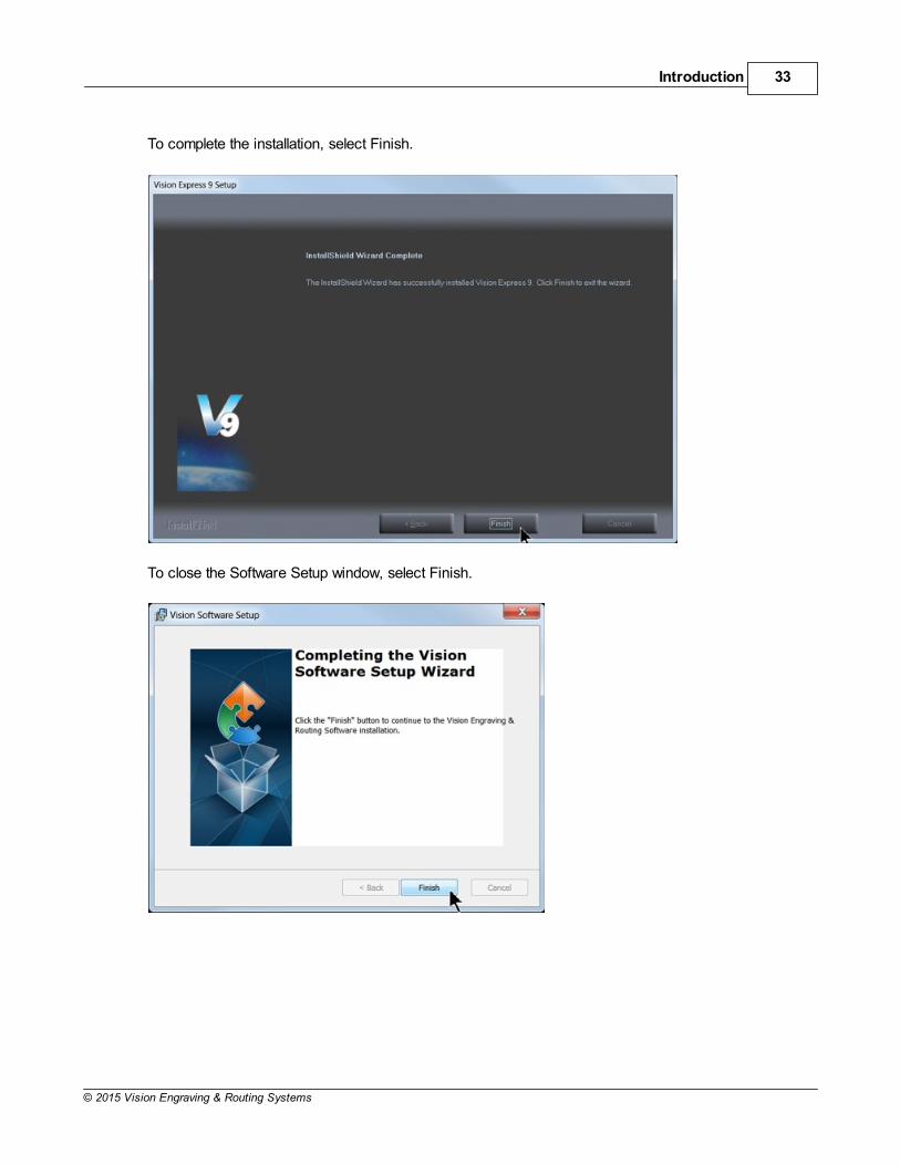
To complete the installation, select Finish.
To close the Software Setup window, select Finish.

Vision Engravers and Routers Installation Guide34
© 2015 Vision Engraving & Routing Systems
Select Exit to close the installer.
The Vision manuals icon should now appear on your computer's desktop along with an icon for yourversion of Vision 9 software.
Clicking on the Vision manuals link will give the user access to User Manuals, Installation Guides,Accessories and Training Videos.
If you were supplied with an Orange Dongle (orange USB stick), keep it installed in your computer'sUSB port in order to use the Vision software. If you were supplied with another color USB stick withyour machine, it can be removed at this time from your computer. Installation is now complete.

Introduction 35
© 2015 Vision Engraving & Routing Systems
2 General Electrical and Facility Requirements by Model
Machine Model Requirements
Express, VE-810, 1612, 1624 Engraver,2424, 2448, MAX and MAX Pro
One 110 VAC 15 Amp or One 220 VAC 10 AmpSingle Phase
1624R, 2525 and 2550 Router - T-Slot TableWith High Frequency Router Head
With Engraving Head
With NSK High Frequency Spindle
One 110 VAC 15 Amp or One 220 VAC 10 AmpSingle Phase (for Vision controller) AND One 220VAC 30 Amp Single Phase (for 3 HP router motor)
One 110 VAC 15 Amp or One 220 VAC 10 AmpSingle Phase
Two 110 VAC 15 Amp, or Two 220 VAC 10 AmpSingle Phase
2550 Router with Vacuum TableWith High Frequency Router Head
With Engraving Head
With NSK High Frequency Spindle
One 110 VAC 15 Amp or One 220 VAC 10 AmpSingle Phase (for Vision controller) AND One 220VAC 30 Amp Single Phase (for 3 HP router motor)AND One 220 VAC 30 Amp 3 Phase (for vacuumtable pump)
One 110 VAC 15 Amp or One 220 VAC 10 AmpSingle Phase (for Vision controller) AND One 220VAC 30 Amp 3 Phase (for vacuum table pump)
Two 110 VAC 15 Amp, or Two 220 VAC 10 AmpSingle Phase AND One 220 VAC 30 Amp 3 Phase(for vacuum table pump)
VR48 Router - T-Slot Table One 220 VAC 50 Amp Single Phase (for Visionmachine) AND One 110 VAC 25 Amp or One 220VAC 15 Amp Single Phase (for extraction unit)
VR48 Router - Vacuum Table One 220 VAC 50 Amp Single Phase (for Visionmachine) AND One 110 VAC 25 Amp or One 220VAC 20 Amp Single Phase (for extraction unit) ANDOne 220 VAC 40 Amp 3 Phase (for vacuum tablepump)
Optional EquipmentEngraving Vacuum Chip RemovalSystem
Router Chip Extraction System
One 110 VAC 15 Amp
One 110 VAC 25 Amp or One 220 VAC 20 AmpSingle Phase
Optional Equipment RequiringCompressed Air Supply
UNIST Misting System
NSK High Frequency Spindle
Clean Dry Compressed Air Supply 60 - 90 PSI Clean Dry Compressed Air Supply 1 SCFM @ 40PSI
NOTE: In addition to the above requirements, a 110 VAC standard outlet is required for the computer.

Vision Engravers and Routers Installation Guide36
© 2015 Vision Engraving & Routing Systems
3 Pendant Holder Installation
Pendant Holder Installation for Phoenix 1212, 16, 24 and 25 Series machines
Your machine is shipped with an optional Pendant Holder to give the user a place to secure thePendant.
To install the Pendant Holder on the Phoenix 1212, follow the below procedure.

Pendant Holder Installation 37
© 2015 Vision Engraving & Routing Systems
To install the Pendant Holder on the 16 Series machines, follow the below procedure.

Vision Engravers and Routers Installation Guide38
© 2015 Vision Engraving & Routing Systems
To install the Pendant Holder on the 25 Series machines, follow the below procedure.

Pendant Holder Installation 39
© 2015 Vision Engraving & Routing Systems
The Pendant Holder for the VR48 can be mounted on the front of the machine. To install the PendantHolder, remove the three screws on the machine and mount the holder to the machine as shown below.Place the Pendant in the Holder to keep it secure when the machine is being used.
VR48 Pendant Holder Installation

Vision Engravers and Routers Installation Guide40
© 2015 Vision Engraving & Routing Systems
4 Express and VE-810
Vision Express and VE-810 Connections
On the rear of the Vision Express and VE810, there are three connection ports. The power port, theEthernet port and the remote on/off port for the optional Vacuum Chip Removal System.
Vision Express (rear view)
For the Vision Express: Connect the power supply cable to a 110 - 220 VAC source, then connect thepower supply plug into the port on the back of the machine. Plug the Ethernet cable into the Ethernetport.
Vision VE810 (rear view)
For the VE810: Connect the power cable to a 110 - 220 VAC source, then plug the power cable into theport on the back of the machine. Plug the Ethernet cable into the Ethernet port.

Express and VE-810 41
© 2015 Vision Engraving & Routing Systems
4.1 Express Layout Diagram
4.2 VE-810 Layout Diagram

Vision Engravers and Routers Installation Guide42
© 2015 Vision Engraving & Routing Systems
5 Phoenix 1212
Phoenix 1212 Engraver/Series 4 Controller Connections
There is only one connection port on the Phoenix 1212. It is a 25 pin Table Cable port on the left sideof the machine. All other connections on the machine's controller are listed below.
1. The engraver's Pendant is connected to the Pendant cable port.
2. The Ethernet Cable from your computer, hub or network is connected to the Ethernet port.
3. The Table Cable connects from 25 pin connector on the engraver to the Table port.
4. The Power Cable connects a 110 - 220 VAC electrical source to the controller and powers thecontroller, table and spindle.
Note: If your machine is equipped with the optional Vacuum Chip Removal System, a remote On/Offcable is connected to the controller to automatically turn the vacuum pump on and off when the job isbeing run.

Phoenix 1212 43
© 2015 Vision Engraving & Routing Systems
5.1 Phoenix 1212 Layout Diagram
Vision Engravers and Routers Installation Guide44
© 2015 Vision Engraving & Routing Systems
6 16 Series and 24 Series Engravers
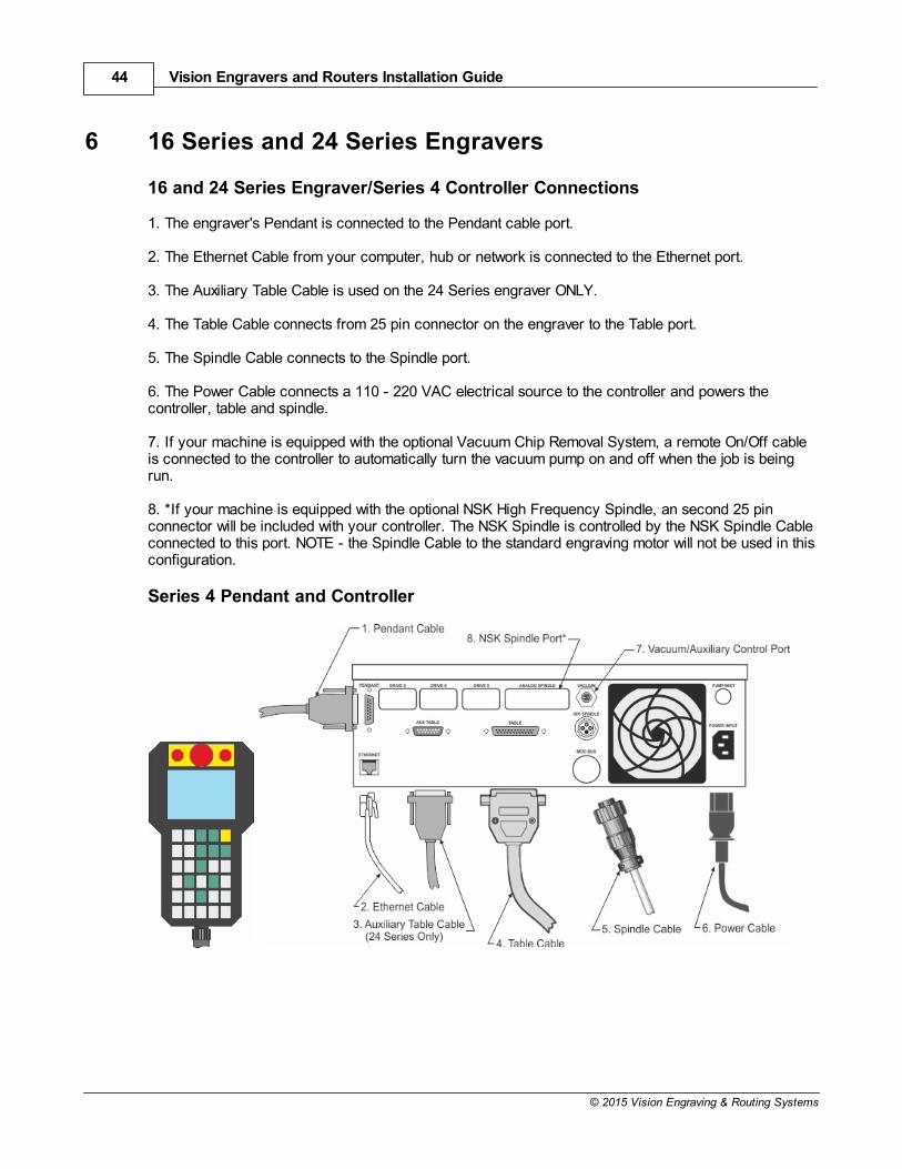
16 and 24 Series Engraver/Series 4 Controller Connections
1. The engraver's Pendant is connected to the Pendant cable port.
2. The Ethernet Cable from your computer, hub or network is connected to the Ethernet port.
3. The Auxiliary Table Cable is used on the 24 Series engraver ONLY.
4. The Table Cable connects from 25 pin connector on the engraver to the Table port.
5. The Spindle Cable connects to the Spindle port.
6. The Power Cable connects a 110 - 220 VAC electrical source to the controller and powers thecontroller, table and spindle.
7. If your machine is equipped with the optional Vacuum Chip Removal System, a remote On/Off cableis connected to the controller to automatically turn the vacuum pump on and off when the job is beingrun.
8. *If your machine is equipped with the optional NSK High Frequency Spindle, an second 25 pinconnector will be included with your controller. The NSK Spindle is controlled by the NSK Spindle Cableconnected to this port. NOTE - the Spindle Cable to the standard engraving motor will not be used in thisconfiguration.
Series 4 Pendant and Controller

16 Series and 24 Series Engravers 45
© 2015 Vision Engraving & Routing Systems
6.1 1612 and 1624 Engraver Layout Diagram

Vision Engravers and Routers Installation Guide46
© 2015 Vision Engraving & Routing Systems
6.2 2424 and 2448 Engraver Layout Diagram

16 Series and 24 Series Engravers 47
© 2015 Vision Engraving & Routing Systems
7 16 Series and 25 Series Routers
7.1 High Frequency Router Head
High Frequency Router Head Wiring Connections
1. The controller Pendant is connected to the Pendant port on the controller.
2. The Ethernet Cable from your computer, hub or network is connected to the Ethernet port on thecontroller
3. The Auxiliary Table Cable is used on the 25 Series machines ONLY. It connects the Serial TableConnector on the machine to the Aux Table port on the controller.
4. The Table Cable connects from 25 Pin Table Connector on the machine to the Table Port on thecontroller
5. The machine's Spindle Cable connects to the Spindle port on the controller.
6. The Power Cable connects a 110 - 220 VAC electrical source to the controller and powers thecontroller and table.
7. The MOD/BUS Cable from the Inverter connects to the MOD/BUS port on the controller and controlsthe High Frequency Router Motor.
Series 4 Controller (rear view) Router Head Connections Pendant

Vision Engravers and Routers Installation Guide48
© 2015 Vision Engraving & Routing Systems
Wiring Connections for Inverter (used with High Frequency Router Head only)
NOTE: The Auxiliary Power Cable is pre-wired on all 16 and 25 Series Routers. Remove Inverter Cover and feed the Auxiliary Power Cable through hole in bottom of Inverter. Connectthe three black wires labeled, T1, T2 and T3, to their respective connection points. Connect the Green(Ground) wire to the connection point shown. Connect the Main Power Cable to a 220VAC source andconnect the MOD/BUS Cable to the machine controller's MOD/BUS port.

16 Series and 25 Series Routers 49
© 2015 Vision Engraving & Routing Systems
Carriage Wiring Connections
The Motor Plug connects to the Spindle Port on the back of the Carriage.
Carriage (rear view)
Mounting the Inverter on the 25 Series Table Stand
The Inverter is mounted on the top-left corner of the machine's stand. There are two flanges mounted onthe rear of the inverter. These flanges are placed in the inside of the stand's legs. Screws are includedwith the inverter to secure the inverter to the stand. Instructions for assembly of the stand are includedwith the stand, which is packed underneath the machine in its shipping crate.

Vision Engravers and Routers Installation Guide50
© 2015 Vision Engraving & Routing Systems

16 Series and 25 Series Routers 51
© 2015 Vision Engraving & Routing Systems
7.2 Engraving Head
Engraving Head Wiring Connections
1. The controller Pendant is connected to the Pendant port on the controller.
2. The Ethernet Cable from your computer, hub or network is connected to the Ethernet port on thecontroller
3. The Auxiliary Table Cable is used on the 25 Series machines ONLY. It connects the Serial Cable Porton the machine to the Aux Table port on the controller.
4. The Table Cable connects from 25 Pin Table Connector on the machine to the Table Port on thecontroller
5. The machine's Spindle Cable connects to the Spindle port on the controller.
6. The Power Cable connects a 110 - 220 VAC electrical source to the controller and powers thecontroller and table.
Series 4 Controller (rear view) Engraving Head Connections Pendant
NOTE: The Auxiliary Power Cable which is pre-wired on all 16 and 25 Series Routers is NOTused with the Engraving Head. If your router was not equipped with the High Frequency RouterHead or the Porter Cable Router Head, this cable can remain disconnected at all times.

Vision Engravers and Routers Installation Guide52
© 2015 Vision Engraving & Routing Systems
Carriage Wiring Connections
The Motor Plug connects to the Spindle Port on the back of the Carriage.
Carriage - rear view

16 Series and 25 Series Routers 53
© 2015 Vision Engraving & Routing Systems
7.3 1624R Router Layout Diagram

Vision Engravers and Routers Installation Guide54
© 2015 Vision Engraving & Routing Systems
7.4 2525 and 2550 Router Layout Diagrams

16 Series and 25 Series Routers 55
© 2015 Vision Engraving & Routing Systems

Vision Engravers and Routers Installation Guide56
© 2015 Vision Engraving & Routing Systems

16 Series and 25 Series Routers 57
© 2015 Vision Engraving & Routing Systems
8 MAX and MAX PRO
Max and Max Pro Connections
The Vision Max and Max Pro machines have an integrated controller inside the base of the machine.The machines need to have the following cables connected to the controller.
1. The engraver's Pendant is connected to the Pendant cable port.
2. The Ethernet Cable from your computer, hub or network is connected to the Ethernet port.
3. The Auxiliary Table Cable is connected to the Aux Table port and powers the machine's rotary axis.
4. The Table Cable connects from 25 pin connector on the engraver to the Table port.
5. The Power Cable connects a 110 - 220 VAC electrical source to the controller and powers thecontroller, table and spindle.
6. The Pump Cable (Max Pro only) connects to the Pump/Mist port and powers the machine's waterpump for glass engraving.
7. Main Power switch (for reference only)
8. If you machine was equipped with the optional Vacuum Chip Removal System, the Vacuum Cablefrom the vacuum pump will connect to the Vacuum port.
Series 4 Pendant and Integrated Controller Connections

Vision Engravers and Routers Installation Guide58
© 2015 Vision Engraving & Routing Systems
8.1 MAX and MAX PRO Layout Diagram
* This dimension is added to allow for clearance on the rear of the machine for cables and for air flow tothe cooling fan.
Vision MAX Vision MAX PRO

MAX and MAX PRO 59
© 2015 Vision Engraving & Routing Systems
9 VR48 Router
9.1 Requirements
Electrical Connections
1. A qualified and licensed electrician must be used to complete all wiring and grounding of themachine according to all state, local, and national electrical codes.
2. Make sure all Junction Boxes and Outlets are mounted according to all state, local and nationalelectrical codes.
3. Junction Box #1 (50 Amp, 220 VAC, Single Phase) will power the router table, spindle, and controls.It is typically mounted on Wall A, approximately 36 to 48 inches above the floor surface. The boxshould be level with the left edge of the router table. (Refer to Installation Layout Diagrams).
4. Junction Box #2 - for machines equipped with Vacuum Tables ONLY - (40 Amp. 220 VAC, 3 Phase)will power the Vacuum Pump. Mounting should be on Wall A and between 36 inches and 48 inchesabove the floor surface. If locating the vacuum pump as shown (Refer to Installation LayoutDiagram), locate Junction Box #2 no greater than 4 feet from Junction Box #1.
5. Outlet #1 (20 Amp, 220 VAC, Single Phase) should be mounted on Wall A as shown (Refer toInstallation Layout Diagram - Section 2.1). This can also be another Junction Box if the DustCollector is to be direct wired to its electrical source. The dust collector is approximately 2 feet x 3feet and is on wheels.
6. Outlet #2 (15 Amp, 110 VAC, Single Phase) should have multiple standard three prong sockets forthe computer. It is typically located near the bottom left corner of the router table (home position) asshown (Refer to Installation Layout Diagram).
7. Wiring needs to be completed to the junction boxes, outlets, etc. before the scheduled firstinstallation/machine orientation day.

Vision Engravers and Routers Installation Guide60
© 2015 Vision Engraving & Routing Systems
Locating the Router
1. A doorway of at least 80 inches wide and 80 inches high is required in order for the router to bemoved into your facility.
2. Locate machine indoors on a flat surface and on a solid foundation.
3. Temperature must remain between 40°F and 85°F.
4. Do not expose machine to direct sunlight, rain, vibration, dampness, or explosive environments.
5. A forklift is required to remove the crate from the shipping truck and to locate the equipment in thebuilding. The forklift must have a minimum capacity of 6,000 lbs and 6' or longer forks.
6. A pallet jack is required to level the router table.
7. The router table footprint is approximately 6.7 feet x 10.7 feet. A designated work area of at least 5feet is strongly recommended around all sides of the machine to ensure ease of operation, materialhandling, cleaning, maintenance and safety.
8. Typically, the vacuum pump is between the router table and Wall A (Refer to Installation LayoutDiagram - Section 2.1). Please note the orientation of the pump and motor.

VR48 Router 61
© 2015 Vision Engraving & Routing Systems
Leveling the machine
1. Make sure the machine has been properly located at your work-site.
2. It is not necessary to bolt your machine to the floor in your facility. However, a solid, stablefoundation is required to support the machine's weight.
3. There should be a leveling bolt in each of the four machine legs.
4. Place a precision leveling gauge on the machine's table top and adjust the leveling bolts until themachine is level in both the horizontal and vertical directions.
Scheduling the Installation
1. Please schedule an electrician for the morning of the first day of installation/machine orientation toconnect the router table, vacuum pump motor, and dust collector to the junction boxes and outlets.
2. If an electrician is not available for the installation, please call Vision ASAP in order to rescheduleinstallation/machine orientation. If Vision personnel arrive and the electrical connections are notready and the electrician is not present, there will be an additional charge $750/day while waiting.
WARNING: The first time the Vacuum Pump is turned on, check that the direction of rotation is correct. Turn it on,then off, observing the direction of rotation. It should match the arrow on the pump near the motor. Ifnecessary, swap any two of the three power leads to change the rotation to the opposite direction.Prolonged usage of the vacuum pump when rotating in the incorrect direction can cause permanentdamage to the pump.

Vision Engravers and Routers Installation Guide62
© 2015 Vision Engraving & Routing Systems
9.2 Wiring Connections
The Main Power Switch is located on the left side of the VR48.
The main power supply is connected to the Main Electrical Box on the left side of the VR48. Removethe cover and make the connections as shown below. Ground is connected to the bare wire andcommon leads are connected to the two shielded wires. The supply for this connection is Junction Box#1 (220 VAC, Single Phase).
Note: The picture below is for illustration purposes only. The power cable should enter the MainElectrical Box through the hole in the left side of the box as shown in the above picture.

VR48 Router 63
© 2015 Vision Engraving & Routing Systems
On the front of the control box for VR48 Router, there are four connection ports; One is an Ethernetport used to connect your computer or network to the on-board Series 4 Controller, the second is forthe Pendant, the third is a USB port used to connect a computer to the VR48 when using the DACSCamera System, and the fourth is to connect the Remote Start Switch for the Dust Collector System.
Plug the network cable (or the crossover cable) into the Ethernet port on the VR48, then either plug thenetwork cable into your network (or hub), or using the crossover cable, plug into the network port onyour computer. Plug the Pendant cable into the Pendant and Pendant Port on the VR48. Connectionsfor the DACS Camera System are detailed in a separate section of this manual. Connect the DustCollector Remote Start Cable to the Remote Start Port using the supplied cable.
NOTE: The crossover cable is colored gray.

Vision Engravers and Routers Installation Guide64
© 2015 Vision Engraving & Routing Systems
The Dust Collector Remote Start Switch will need to be connected. For ease of operation, a remote startswitch and cables can be used to turn on the dust collector automatically when a job is being run. Thesupply for this connection is from Outlet #1 (220 VAC, Single Phase, 20 Amp).

VR48 Router 65
© 2015 Vision Engraving & Routing Systems
Wiring for this switch is shown below. The input and output wires should be connected as shown. Bothinput and output ground wires can be connected to the single GND location shown. The switch can bewall mounted at a location convenient for the user.
The Remote Start Cable is connected to the Remote Start Port on the front of the machine's control box.

Vision Engravers and Routers Installation Guide66
© 2015 Vision Engraving & Routing Systems
9.3 Vacuum Pump Connections - Vacuum Table Models Only
The Main Vacuum Port for the VR48 is located at the foot of the machine. To connect the vacuum pumpto the machine, use the supplied 3" diameter vacuum hose and connect one end to the vacuum pumpand the other end to the Main Vacuum Port on the machine.
The vacuum pump has been equipped with an electrical connector designed for a 40 amp, 220 VAC, 3phase power supply. A qualified and licensed electrician must be used to complete all wiring andgrounding of the vacuum pump according to all state, local, and national electrical codes.

VR48 Router 67
© 2015 Vision Engraving & Routing Systems
9.4 VR48 Router Layout Diagrams
T-Slot Tables Models

Vision Engravers and Routers Installation Guide68
© 2015 Vision Engraving & Routing Systems
Vacuum Table Models