virtuoso xl layout editor user guide - iowa state...
TRANSCRIPT

Virtuoso® XL Layout Editor User Guide
Product Version 5.1.41September 2006

1995-2006 Cadence Design Systems, Inc. All rights reserved.Printed in the United States of America.
Cadence Design Systems, Inc., 555 River Oaks Parkway, San Jose, CA 95134, USA
Trademarks: Trademarks and service marks of Cadence Design Systems, Inc. (Cadence) contained inthis document are attributed to Cadence with the appropriate symbol. For queries regarding Cadence’strademarks, contact the corporate legal department at the address shown above or call 1-800-862-4522.
All other trademarks are the property of their respective holders.
Restricted Print Permission: This publication is protected by copyright and any unauthorized use of thispublication may violate copyright, trademark, and other laws. Except as specified in this permissionstatement, this publication may not be copied, reproduced, modified, published, uploaded, posted,transmitted, or distributed in any way, without prior written permission from Cadence. This statement grantsyou permission to print one (1) hard copy of this publication subject to the following conditions:
1. The publication may be used solely for personal, informational, and noncommercial purposes;2. The publication may not be modified in any way;3. Any copy of the publication or portion thereof must include all original copyright, trademark, and other
proprietary notices and this permission statement; and4. Cadence reserves the right to revoke this authorization at any time, and any such use shall be
discontinued immediately upon written notice from Cadence.
Disclaimer: Information in this publication is subject to change without notice and does not represent acommitment on the part of Cadence. The information contained herein is the proprietary and confidentialinformation of Cadence or its licensors, and is supplied subject to, and may be used only by Cadence’scustomer in accordance with, a written agreement between Cadence and its customer. Except as may beexplicitly set forth in such agreement, Cadence does not make, and expressly disclaims, anyrepresentations or warranties as to the completeness, accuracy or usefulness of the information containedin this document. Cadence does not warrant that use of such information will not infringe any third partyrights, nor does Cadence assume any liability for damages or costs of any kind that may result from use ofsuch information.
Restricted Rights: Use, duplication, or disclosure by the Government is subject to restrictions as set forthin FAR52.227-14 and DFAR252.227-7013 et seq. or its successor.
Virtuoso XL Layout Editor User Guide
Contents
Preface . . . . . . . . . . . . . . . . . . . . . . . . . . . . . . . . . . . . . . . . . . . . . . . . . . . . . . . . . . . . . 25
Related Documents . . . . . . . . . . . . . . . . . . . . . . . . . . . . . . . . . . . . . . . . . . . . . . . . . . . . . 25Installation, Environment, and Infrastructure . . . . . . . . . . . . . . . . . . . . . . . . . . . . . . . 25Technology Information . . . . . . . . . . . . . . . . . . . . . . . . . . . . . . . . . . . . . . . . . . . . . . . 26Virtuoso Tools . . . . . . . . . . . . . . . . . . . . . . . . . . . . . . . . . . . . . . . . . . . . . . . . . . . . . . . 26Relative Object Design and Inherited Connections . . . . . . . . . . . . . . . . . . . . . . . . . . 26
Typographic and Syntax Conventions . . . . . . . . . . . . . . . . . . . . . . . . . . . . . . . . . . . . . . . 27
1Introduction . . . . . . . . . . . . . . . . . . . . . . . . . . . . . . . . . . . . . . . . . . . . . . . . . . . . . . . . 29
2Editing Your Technology File . . . . . . . . . . . . . . . . . . . . . . . . . . . . . . . . . . . . 31
Technology File Requirements . . . . . . . . . . . . . . . . . . . . . . . . . . . . . . . . . . . . . . . . . . . . 31Layer Rules . . . . . . . . . . . . . . . . . . . . . . . . . . . . . . . . . . . . . . . . . . . . . . . . . . . . . . . . 32Devices . . . . . . . . . . . . . . . . . . . . . . . . . . . . . . . . . . . . . . . . . . . . . . . . . . . . . . . . . . . . 33Physical Rules . . . . . . . . . . . . . . . . . . . . . . . . . . . . . . . . . . . . . . . . . . . . . . . . . . . . . . 34Virtuoso XL Rules (lxRules) . . . . . . . . . . . . . . . . . . . . . . . . . . . . . . . . . . . . . . . . . . . . 34Compactor Rules . . . . . . . . . . . . . . . . . . . . . . . . . . . . . . . . . . . . . . . . . . . . . . . . . . . . 36
Sample Technology File . . . . . . . . . . . . . . . . . . . . . . . . . . . . . . . . . . . . . . . . . . . . . . . . . . 38
3Preparing Your Connectivity Source. . . . . . . . . . . . . . . . . . . . . . . . . . . . 39
Placing Design Elements . . . . . . . . . . . . . . . . . . . . . . . . . . . . . . . . . . . . . . . . . . . . . . . . . 39Using Design Variables . . . . . . . . . . . . . . . . . . . . . . . . . . . . . . . . . . . . . . . . . . . . . . . . . . 40
Netlist Processor Expressions . . . . . . . . . . . . . . . . . . . . . . . . . . . . . . . . . . . . . . . . . . 40Analog Expression Language Expressions . . . . . . . . . . . . . . . . . . . . . . . . . . . . . . . . 41Simulation Design Variables . . . . . . . . . . . . . . . . . . . . . . . . . . . . . . . . . . . . . . . . . . . . 42
Using One-to-Many Mapping . . . . . . . . . . . . . . . . . . . . . . . . . . . . . . . . . . . . . . . . . . . . . . 42Iterated Instances and Bus Pins . . . . . . . . . . . . . . . . . . . . . . . . . . . . . . . . . . . . . . . . . 42
September 2006 3 Product Version 5.1.41

Virtuoso XL Layout Editor User Guide
Preparing a Library for use with Quick Cells . . . . . . . . . . . . . . . . . . . . . . . . . . . . . . . . . . 43Creating a New Library to Use With QCells . . . . . . . . . . . . . . . . . . . . . . . . . . . . . . . . 44Setting Units Correctly for QCells . . . . . . . . . . . . . . . . . . . . . . . . . . . . . . . . . . . . . . . . 47Using an Existing Library . . . . . . . . . . . . . . . . . . . . . . . . . . . . . . . . . . . . . . . . . . . . . . 47Inserting a QCell Device . . . . . . . . . . . . . . . . . . . . . . . . . . . . . . . . . . . . . . . . . . . . . . . 48Using Layout Optimization . . . . . . . . . . . . . . . . . . . . . . . . . . . . . . . . . . . . . . . . . . . . . 49
Using Properties . . . . . . . . . . . . . . . . . . . . . . . . . . . . . . . . . . . . . . . . . . . . . . . . . . . . . . . 49Property Definitions . . . . . . . . . . . . . . . . . . . . . . . . . . . . . . . . . . . . . . . . . . . . . . . . . . 49
Preparing Pins . . . . . . . . . . . . . . . . . . . . . . . . . . . . . . . . . . . . . . . . . . . . . . . . . . . . . . . . . 51Extra Pins in the Symbol or Layout Views . . . . . . . . . . . . . . . . . . . . . . . . . . . . . . . . . 52External Connections . . . . . . . . . . . . . . . . . . . . . . . . . . . . . . . . . . . . . . . . . . . . . . . . . 52
4Setting Up the Virtuoso XL Environment . . . . . . . . . . . . . . . . . . . . . . 55
Setting Up Your Desktop . . . . . . . . . . . . . . . . . . . . . . . . . . . . . . . . . . . . . . . . . . . . . . . . . 56Customizing Your Desktop Layout . . . . . . . . . . . . . . . . . . . . . . . . . . . . . . . . . . . . . . . 56Using Multiple Cellviews . . . . . . . . . . . . . . . . . . . . . . . . . . . . . . . . . . . . . . . . . . . . . . . 57Printing to the Command Interpreter Window . . . . . . . . . . . . . . . . . . . . . . . . . . . . . . 57
Changing Display Colors . . . . . . . . . . . . . . . . . . . . . . . . . . . . . . . . . . . . . . . . . . . . . . . . . 58Editing Entry Layers . . . . . . . . . . . . . . . . . . . . . . . . . . . . . . . . . . . . . . . . . . . . . . . . . . 58
Using Bindkeys . . . . . . . . . . . . . . . . . . . . . . . . . . . . . . . . . . . . . . . . . . . . . . . . . . . . . . . . 61Displaying Bindkeys . . . . . . . . . . . . . . . . . . . . . . . . . . . . . . . . . . . . . . . . . . . . . . . . . . 61Loading Bindkeys . . . . . . . . . . . . . . . . . . . . . . . . . . . . . . . . . . . . . . . . . . . . . . . . . . . . 62
Setting Environment Variables . . . . . . . . . . . . . . . . . . . . . . . . . . . . . . . . . . . . . . . . . . . . . 62Using the Layout XL Options Form . . . . . . . . . . . . . . . . . . . . . . . . . . . . . . . . . . . . . . 62Using Setup Files or the CIW . . . . . . . . . . . . . . . . . . . . . . . . . . . . . . . . . . . . . . . . . . . 64
Online Forms . . . . . . . . . . . . . . . . . . . . . . . . . . . . . . . . . . . . . . . . . . . . . . . . . . . . . . . . . . 65Layout XL Options . . . . . . . . . . . . . . . . . . . . . . . . . . . . . . . . . . . . . . . . . . . . . . . . . . . 65
5Device Abutment. . . . . . . . . . . . . . . . . . . . . . . . . . . . . . . . . . . . . . . . . . . . . . . . . . 71
Requirements for Abutment . . . . . . . . . . . . . . . . . . . . . . . . . . . . . . . . . . . . . . . . . . . . . . . 72Setting Up Cells for Abutment . . . . . . . . . . . . . . . . . . . . . . . . . . . . . . . . . . . . . . . . . . . . . 73
Snapping Instances in the Direction Perpendicular to the Abutment . . . . . . . . . . . . . 74Multiple Pins . . . . . . . . . . . . . . . . . . . . . . . . . . . . . . . . . . . . . . . . . . . . . . . . . . . . . . . . 74
September 2006 4 Product Version 5.1.41

Virtuoso XL Layout Editor User Guide
Additional Pins on Ignored Instances . . . . . . . . . . . . . . . . . . . . . . . . . . . . . . . . . . . . . 74Steps in Automatic Abutment . . . . . . . . . . . . . . . . . . . . . . . . . . . . . . . . . . . . . . . . . . . 75Sample Parameterized Cells Set Up for Abutment . . . . . . . . . . . . . . . . . . . . . . . . . . . 75
Creating CMOS Pcells to Use with Abutment . . . . . . . . . . . . . . . . . . . . . . . . . . . . . . . . . 78MOS Abutment without a User-Defined abutFunction . . . . . . . . . . . . . . . . . . . . . . . . . . . 81
Automatic Abutment Properties . . . . . . . . . . . . . . . . . . . . . . . . . . . . . . . . . . . . . . . . . 81Manual Device Abutment . . . . . . . . . . . . . . . . . . . . . . . . . . . . . . . . . . . . . . . . . . . . . . . . . 81
Chaining Transistors Interactively . . . . . . . . . . . . . . . . . . . . . . . . . . . . . . . . . . . . . . . . 82Chaining Transistors during Pick From Schematic . . . . . . . . . . . . . . . . . . . . . . . . . . . 85Moving Chained Transistors . . . . . . . . . . . . . . . . . . . . . . . . . . . . . . . . . . . . . . . . . . . . 86
Automatic Device Abutment . . . . . . . . . . . . . . . . . . . . . . . . . . . . . . . . . . . . . . . . . . . . . . . 88Chaining Transistors Automatically during Layout Generation . . . . . . . . . . . . . . . . . . 89Chaining Transistors Automatically during Update Components and Nets . . . . . . . . 89
Abutting Parameterized Cells and Quick Cells . . . . . . . . . . . . . . . . . . . . . . . . . . . . . . . . 90
6Generating Your Layout . . . . . . . . . . . . . . . . . . . . . . . . . . . . . . . . . . . . . . . . . . 91
Naming Conventions . . . . . . . . . . . . . . . . . . . . . . . . . . . . . . . . . . . . . . . . . . . . . . . . . . . . 91Starting Virtuoso XL from the Schematic . . . . . . . . . . . . . . . . . . . . . . . . . . . . . . . . . . . . . 94Importing a Netlist for a Connectivity Reference . . . . . . . . . . . . . . . . . . . . . . . . . . . . . . . 96Starting Virtuoso XL from the Layout View . . . . . . . . . . . . . . . . . . . . . . . . . . . . . . . . . . . 98
Connectivity Reference as a Netlist . . . . . . . . . . . . . . . . . . . . . . . . . . . . . . . . . . . . . 100Virtuoso XL Map File Structure . . . . . . . . . . . . . . . . . . . . . . . . . . . . . . . . . . . . . . . . 102Using a Map File in a Schematic Driven Flow . . . . . . . . . . . . . . . . . . . . . . . . . . . . . 104
Defining the Design Boundary . . . . . . . . . . . . . . . . . . . . . . . . . . . . . . . . . . . . . . . . . . . . 105Automatic Area Estimation . . . . . . . . . . . . . . . . . . . . . . . . . . . . . . . . . . . . . . . . . . . . 106User-Defined Area Estimation Functions . . . . . . . . . . . . . . . . . . . . . . . . . . . . . . . . . 107
Working with Template Files . . . . . . . . . . . . . . . . . . . . . . . . . . . . . . . . . . . . . . . . . . . . . 109Saving Form Contents . . . . . . . . . . . . . . . . . . . . . . . . . . . . . . . . . . . . . . . . . . . . . . . 110Loading Template Files . . . . . . . . . . . . . . . . . . . . . . . . . . . . . . . . . . . . . . . . . . . . . . 110Modifying Template Files . . . . . . . . . . . . . . . . . . . . . . . . . . . . . . . . . . . . . . . . . . . . . 111Loading Template Files . . . . . . . . . . . . . . . . . . . . . . . . . . . . . . . . . . . . . . . . . . . . . . 111Creating Template Files . . . . . . . . . . . . . . . . . . . . . . . . . . . . . . . . . . . . . . . . . . . . . . 112Template File Syntax . . . . . . . . . . . . . . . . . . . . . . . . . . . . . . . . . . . . . . . . . . . . . . . . 113General Syntax Rules . . . . . . . . . . . . . . . . . . . . . . . . . . . . . . . . . . . . . . . . . . . . . . . 114
September 2006 5 Product Version 5.1.41
Virtuoso XL Layout Editor User Guide
Header Section . . . . . . . . . . . . . . . . . . . . . . . . . . . . . . . . . . . . . . . . . . . . . . . . . . . . . 117Boundaries Section . . . . . . . . . . . . . . . . . . . . . . . . . . . . . . . . . . . . . . . . . . . . . . . . . 117I/O Pins Section . . . . . . . . . . . . . . . . . . . . . . . . . . . . . . . . . . . . . . . . . . . . . . . . . . . . 118Sample Template . . . . . . . . . . . . . . . . . . . . . . . . . . . . . . . . . . . . . . . . . . . . . . . . . . . 122
Generating a Layout with Components Not Placed (Gen From Source) . . . . . . . . . . . . 123Generating a Layout from Source . . . . . . . . . . . . . . . . . . . . . . . . . . . . . . . . . . . . . . 124Mismatched Pins . . . . . . . . . . . . . . . . . . . . . . . . . . . . . . . . . . . . . . . . . . . . . . . . . . . 134Using CDF Callbacks with Layout Generation . . . . . . . . . . . . . . . . . . . . . . . . . . . . . 134
Placing Components in a Layout in the Same Relative Position as in the Schematic (Place AsIn Schematic) . . . . . . . . . . . . . . . . . . . . . . . . . . . . . . . . . . . . . . . . . . . . . . . . . . . . . . . . . 134Moving Components from the Schematic into the Layout (Pick from Schematic) . . . . . 135
Placing a Group of Schematic Elements Together . . . . . . . . . . . . . . . . . . . . . . . . . . 136Placing Individual Components . . . . . . . . . . . . . . . . . . . . . . . . . . . . . . . . . . . . . . . . 139Generating Pins . . . . . . . . . . . . . . . . . . . . . . . . . . . . . . . . . . . . . . . . . . . . . . . . . . . . 141Viewing Unplaced Instances/Pins . . . . . . . . . . . . . . . . . . . . . . . . . . . . . . . . . . . . . . 142Viewing in Place . . . . . . . . . . . . . . . . . . . . . . . . . . . . . . . . . . . . . . . . . . . . . . . . . . . . 143Using CDF Callbacks with Pick From Schematic . . . . . . . . . . . . . . . . . . . . . . . . . . . 143
Cloning . . . . . . . . . . . . . . . . . . . . . . . . . . . . . . . . . . . . . . . . . . . . . . . . . . . . . . . . . . . . . . 144Exact and Non-Exact Matches . . . . . . . . . . . . . . . . . . . . . . . . . . . . . . . . . . . . . . . . . 144Cloning Mfactored Components . . . . . . . . . . . . . . . . . . . . . . . . . . . . . . . . . . . . . . . . 145Cloning a Component . . . . . . . . . . . . . . . . . . . . . . . . . . . . . . . . . . . . . . . . . . . . . . . . 149Modifying the Correspondence . . . . . . . . . . . . . . . . . . . . . . . . . . . . . . . . . . . . . . . . 152Cloning a Group of Components . . . . . . . . . . . . . . . . . . . . . . . . . . . . . . . . . . . . . . . 154Cloning between Multiple Cellviews . . . . . . . . . . . . . . . . . . . . . . . . . . . . . . . . . . . . . 154Creating Correspondence Points . . . . . . . . . . . . . . . . . . . . . . . . . . . . . . . . . . . . . . . 155Displaying Correspondence Points . . . . . . . . . . . . . . . . . . . . . . . . . . . . . . . . . . . . . . 156Removing Correspondence Points . . . . . . . . . . . . . . . . . . . . . . . . . . . . . . . . . . . . . . 157
Online Forms . . . . . . . . . . . . . . . . . . . . . . . . . . . . . . . . . . . . . . . . . . . . . . . . . . . . . . . . . 158Add Correspondence Pairs . . . . . . . . . . . . . . . . . . . . . . . . . . . . . . . . . . . . . . . . . . . 159Cloning . . . . . . . . . . . . . . . . . . . . . . . . . . . . . . . . . . . . . . . . . . . . . . . . . . . . . . . . . . . 159Correspondence Pairs . . . . . . . . . . . . . . . . . . . . . . . . . . . . . . . . . . . . . . . . . . . . . . . 161Define Connectivity Reference . . . . . . . . . . . . . . . . . . . . . . . . . . . . . . . . . . . . . . . . . 161Display Specific Correspondence Components . . . . . . . . . . . . . . . . . . . . . . . . . . . . 162Import XL Netlist . . . . . . . . . . . . . . . . . . . . . . . . . . . . . . . . . . . . . . . . . . . . . . . . . . . . 162Layout Generation Options . . . . . . . . . . . . . . . . . . . . . . . . . . . . . . . . . . . . . . . . . . . . 163Modify Correspondence . . . . . . . . . . . . . . . . . . . . . . . . . . . . . . . . . . . . . . . . . . . . . . 167
September 2006 6 Product Version 5.1.41
Virtuoso XL Layout Editor User Guide
Open File . . . . . . . . . . . . . . . . . . . . . . . . . . . . . . . . . . . . . . . . . . . . . . . . . . . . . . . . . 167Pick from Schematic . . . . . . . . . . . . . . . . . . . . . . . . . . . . . . . . . . . . . . . . . . . . . . . . . 168Remove Correspondence Components . . . . . . . . . . . . . . . . . . . . . . . . . . . . . . . . . . 170Set Pin Label Text Style . . . . . . . . . . . . . . . . . . . . . . . . . . . . . . . . . . . . . . . . . . . . . . 170Startup Option . . . . . . . . . . . . . . . . . . . . . . . . . . . . . . . . . . . . . . . . . . . . . . . . . . . . . 172Template File . . . . . . . . . . . . . . . . . . . . . . . . . . . . . . . . . . . . . . . . . . . . . . . . . . . . . . 172
7Editing Your Layout . . . . . . . . . . . . . . . . . . . . . . . . . . . . . . . . . . . . . . . . . . . . . . 173
Identifying Incomplete Nets . . . . . . . . . . . . . . . . . . . . . . . . . . . . . . . . . . . . . . . . . . . . . . 174Moving Objects Manually . . . . . . . . . . . . . . . . . . . . . . . . . . . . . . . . . . . . . . . . . . . . . . . . 177
Moving Objects Using Move Options . . . . . . . . . . . . . . . . . . . . . . . . . . . . . . . . . . . . 178Setting the Move Form to Appear Automatically . . . . . . . . . . . . . . . . . . . . . . . . . . . 182
Swapping Components . . . . . . . . . . . . . . . . . . . . . . . . . . . . . . . . . . . . . . . . . . . . . . . . . 182Permuting Component Pins . . . . . . . . . . . . . . . . . . . . . . . . . . . . . . . . . . . . . . . . . . . . . . 183
Permuting Pins Manually . . . . . . . . . . . . . . . . . . . . . . . . . . . . . . . . . . . . . . . . . . . . . 185Checking Permutation Information . . . . . . . . . . . . . . . . . . . . . . . . . . . . . . . . . . . . . . 186Updating Permuted Pins . . . . . . . . . . . . . . . . . . . . . . . . . . . . . . . . . . . . . . . . . . . . . . 187
Using Device Locking . . . . . . . . . . . . . . . . . . . . . . . . . . . . . . . . . . . . . . . . . . . . . . . . . . 187Component Types . . . . . . . . . . . . . . . . . . . . . . . . . . . . . . . . . . . . . . . . . . . . . . . . . . . . . 188
MOS Transistor Chaining and Folding Parameters . . . . . . . . . . . . . . . . . . . . . . . . . 188Defining a Component Type . . . . . . . . . . . . . . . . . . . . . . . . . . . . . . . . . . . . . . . . . . . 190Modifying a Component Type . . . . . . . . . . . . . . . . . . . . . . . . . . . . . . . . . . . . . . . . . . 193
Using Transistor Folding . . . . . . . . . . . . . . . . . . . . . . . . . . . . . . . . . . . . . . . . . . . . . . . . 193Folding Transistors . . . . . . . . . . . . . . . . . . . . . . . . . . . . . . . . . . . . . . . . . . . . . . . . . . 194
Adding Instances to a Layout . . . . . . . . . . . . . . . . . . . . . . . . . . . . . . . . . . . . . . . . . . . . . 197Adding Pins to a Layout . . . . . . . . . . . . . . . . . . . . . . . . . . . . . . . . . . . . . . . . . . . . . . . . . 199Assigning Pins to a Net . . . . . . . . . . . . . . . . . . . . . . . . . . . . . . . . . . . . . . . . . . . . . . . . . 201Using Edit-In-Place . . . . . . . . . . . . . . . . . . . . . . . . . . . . . . . . . . . . . . . . . . . . . . . . . . . . 202
Setting the Default Application . . . . . . . . . . . . . . . . . . . . . . . . . . . . . . . . . . . . . . . . . 203Online Forms . . . . . . . . . . . . . . . . . . . . . . . . . . . . . . . . . . . . . . . . . . . . . . . . . . . . . . . . . 203
Assign Nets . . . . . . . . . . . . . . . . . . . . . . . . . . . . . . . . . . . . . . . . . . . . . . . . . . . . . . . 204Edit Component Types . . . . . . . . . . . . . . . . . . . . . . . . . . . . . . . . . . . . . . . . . . . . . . . 204Move . . . . . . . . . . . . . . . . . . . . . . . . . . . . . . . . . . . . . . . . . . . . . . . . . . . . . . . . . . . . . 206Set Transistor Folding . . . . . . . . . . . . . . . . . . . . . . . . . . . . . . . . . . . . . . . . . . . . . . . . 207
September 2006 7 Product Version 5.1.41
Virtuoso XL Layout Editor User Guide
Show Incomplete Nets . . . . . . . . . . . . . . . . . . . . . . . . . . . . . . . . . . . . . . . . . . . . . . . 208Stretch . . . . . . . . . . . . . . . . . . . . . . . . . . . . . . . . . . . . . . . . . . . . . . . . . . . . . . . . . . . 210Alignment Form . . . . . . . . . . . . . . . . . . . . . . . . . . . . . . . . . . . . . . . . . . . . . . . . . . . . 211
8Using the Placer . . . . . . . . . . . . . . . . . . . . . . . . . . . . . . . . . . . . . . . . . . . . . . . . . 213
Main Features . . . . . . . . . . . . . . . . . . . . . . . . . . . . . . . . . . . . . . . . . . . . . . . . . . . . . . 213Place Menu Command Summary . . . . . . . . . . . . . . . . . . . . . . . . . . . . . . . . . . . . . . 214Other Commands Used with the Placer . . . . . . . . . . . . . . . . . . . . . . . . . . . . . . . . . . 215Placement Styles . . . . . . . . . . . . . . . . . . . . . . . . . . . . . . . . . . . . . . . . . . . . . . . . . . . 215
Setting Up Virtuoso XL for Placement . . . . . . . . . . . . . . . . . . . . . . . . . . . . . . . . . . . . . . 217Identifying the Placement Translation Rules . . . . . . . . . . . . . . . . . . . . . . . . . . . . . . . 217Setting Cadence Design Framework II Environment Variables . . . . . . . . . . . . . . . . 218Setting MOS Chaining and Folding Parameters . . . . . . . . . . . . . . . . . . . . . . . . . . . . 219Defining the Boundary Layer (Placement Region) . . . . . . . . . . . . . . . . . . . . . . . . . . 219Abutting Standard Cells . . . . . . . . . . . . . . . . . . . . . . . . . . . . . . . . . . . . . . . . . . . . . . 219Using Automatic Abutment During Placement . . . . . . . . . . . . . . . . . . . . . . . . . . . . . 220
Placement Constraints . . . . . . . . . . . . . . . . . . . . . . . . . . . . . . . . . . . . . . . . . . . . . . . . . . 221Constraint Manager Geometric Constraints . . . . . . . . . . . . . . . . . . . . . . . . . . . . . . . 221Pin Placement Constraints . . . . . . . . . . . . . . . . . . . . . . . . . . . . . . . . . . . . . . . . . . . . 226Constraint Limitations . . . . . . . . . . . . . . . . . . . . . . . . . . . . . . . . . . . . . . . . . . . . . . . . 227
Placement Parameters and Component Types . . . . . . . . . . . . . . . . . . . . . . . . . . . . . . . 227MOS Transistor Chaining and Folding Parameters . . . . . . . . . . . . . . . . . . . . . . . . . 229Defining Standard Cell Substrate Contacts . . . . . . . . . . . . . . . . . . . . . . . . . . . . . . . 229
Pin Placement . . . . . . . . . . . . . . . . . . . . . . . . . . . . . . . . . . . . . . . . . . . . . . . . . . . . . . . . 230Placing a Pin on a Boundary Edge . . . . . . . . . . . . . . . . . . . . . . . . . . . . . . . . . . . . . . 231Placing Ordered Pins on a Boundary Edge . . . . . . . . . . . . . . . . . . . . . . . . . . . . . . . 232Placing a Pin in a Fixed Position not on the Boundary . . . . . . . . . . . . . . . . . . . . . . . 233Placing a Pin on a Lower-level Instance Terminal . . . . . . . . . . . . . . . . . . . . . . . . . . 233Assigning Spacing Between Pins . . . . . . . . . . . . . . . . . . . . . . . . . . . . . . . . . . . . . . . 234Converting a Pin into a Rail . . . . . . . . . . . . . . . . . . . . . . . . . . . . . . . . . . . . . . . . . . . 234Converting a Rail into a Pin . . . . . . . . . . . . . . . . . . . . . . . . . . . . . . . . . . . . . . . . . . . 235Loading a Template File . . . . . . . . . . . . . . . . . . . . . . . . . . . . . . . . . . . . . . . . . . . . . . 236
Saving Pin Placement to a Template File . . . . . . . . . . . . . . . . . . . . . . . . . . . . . . . . . . . 236Partitioning the Design . . . . . . . . . . . . . . . . . . . . . . . . . . . . . . . . . . . . . . . . . . . . . . . . . . 237
September 2006 8 Product Version 5.1.41
Virtuoso XL Layout Editor User Guide
Creating a Partition . . . . . . . . . . . . . . . . . . . . . . . . . . . . . . . . . . . . . . . . . . . . . . . . . . 238Loading Information from a Template File . . . . . . . . . . . . . . . . . . . . . . . . . . . . . . . . 240Saving Partitions to a Template File . . . . . . . . . . . . . . . . . . . . . . . . . . . . . . . . . . . . . 241
Setting Placement Planning . . . . . . . . . . . . . . . . . . . . . . . . . . . . . . . . . . . . . . . . . . . . . . 241Assisted CMOS Placement . . . . . . . . . . . . . . . . . . . . . . . . . . . . . . . . . . . . . . . . . . . 241Using Assisted Standard Cell Mode . . . . . . . . . . . . . . . . . . . . . . . . . . . . . . . . . . . . . 251Manual User-Defined Row-Based Placement . . . . . . . . . . . . . . . . . . . . . . . . . . . . . 255Defining User-Programmed Styles . . . . . . . . . . . . . . . . . . . . . . . . . . . . . . . . . . . . . . 257Choose Component Types Form . . . . . . . . . . . . . . . . . . . . . . . . . . . . . . . . . . . . . . . 264
Running the Placer . . . . . . . . . . . . . . . . . . . . . . . . . . . . . . . . . . . . . . . . . . . . . . . . . . . . 265Prerequisites to Placement . . . . . . . . . . . . . . . . . . . . . . . . . . . . . . . . . . . . . . . . . . . 266Running the Placer: Initial Placement . . . . . . . . . . . . . . . . . . . . . . . . . . . . . . . . . . . 266Stopping the Placer . . . . . . . . . . . . . . . . . . . . . . . . . . . . . . . . . . . . . . . . . . . . . . . . . 269Running Load Balancing Service (LBS) . . . . . . . . . . . . . . . . . . . . . . . . . . . . . . . . . . 269Troubleshooting Placement Results . . . . . . . . . . . . . . . . . . . . . . . . . . . . . . . . . . . . . 269Refining Placement Results . . . . . . . . . . . . . . . . . . . . . . . . . . . . . . . . . . . . . . . . . . . 269Running the Placer: Detailed Placement . . . . . . . . . . . . . . . . . . . . . . . . . . . . . . . . . 270
Showing Congestions . . . . . . . . . . . . . . . . . . . . . . . . . . . . . . . . . . . . . . . . . . . . . . . . . . 270Troubleshooting Placement . . . . . . . . . . . . . . . . . . . . . . . . . . . . . . . . . . . . . . . . . . . . . . 271
Error Messages . . . . . . . . . . . . . . . . . . . . . . . . . . . . . . . . . . . . . . . . . . . . . . . . . . . . 271Online Forms . . . . . . . . . . . . . . . . . . . . . . . . . . . . . . . . . . . . . . . . . . . . . . . . . . . . . . . . . 271
Auto Placer . . . . . . . . . . . . . . . . . . . . . . . . . . . . . . . . . . . . . . . . . . . . . . . . . . . . . . . . 272Partitioning . . . . . . . . . . . . . . . . . . . . . . . . . . . . . . . . . . . . . . . . . . . . . . . . . . . . . . . . 275Choose Component Types . . . . . . . . . . . . . . . . . . . . . . . . . . . . . . . . . . . . . . . . . . . . 277Pin Placement . . . . . . . . . . . . . . . . . . . . . . . . . . . . . . . . . . . . . . . . . . . . . . . . . . . . . 277Load Template File . . . . . . . . . . . . . . . . . . . . . . . . . . . . . . . . . . . . . . . . . . . . . . . . . . 280Placement Planning . . . . . . . . . . . . . . . . . . . . . . . . . . . . . . . . . . . . . . . . . . . . . . . . . 280Placement Planning (Assisted Standard-Cell) . . . . . . . . . . . . . . . . . . . . . . . . . . . . . 284Placement Planning (Assisted Mixed CMOS/Standard-Cell) . . . . . . . . . . . . . . . . . . 287Placement Planning (Manual User-Defined) . . . . . . . . . . . . . . . . . . . . . . . . . . . . . . 292
9Preparing Your Design for Routing . . . . . . . . . . . . . . . . . . . . . . . . . . . . 295
Connectivity Extraction . . . . . . . . . . . . . . . . . . . . . . . . . . . . . . . . . . . . . . . . . . . . . . . . . 296Top-Level Design Extraction . . . . . . . . . . . . . . . . . . . . . . . . . . . . . . . . . . . . . . . . . . . 297
September 2006 9 Product Version 5.1.41
Virtuoso XL Layout Editor User Guide
Hierarchical Extraction . . . . . . . . . . . . . . . . . . . . . . . . . . . . . . . . . . . . . . . . . . . . . . . 298Via Mosaic Support (CDB only) . . . . . . . . . . . . . . . . . . . . . . . . . . . . . . . . . . . . . . . . 302
Pseudo-Parallel Connections . . . . . . . . . . . . . . . . . . . . . . . . . . . . . . . . . . . . . . . . . . . . . 302What is a Pseudo-Parallel Connection . . . . . . . . . . . . . . . . . . . . . . . . . . . . . . . . . . . 303Examples of Pseudo-Parallel Connections . . . . . . . . . . . . . . . . . . . . . . . . . . . . . . . 304Defining a Pseudo Parallel Connection . . . . . . . . . . . . . . . . . . . . . . . . . . . . . . . . . . 307Resetting a Pseudo-Parallel Connection . . . . . . . . . . . . . . . . . . . . . . . . . . . . . . . . . 308Generating a Layout without Chaining and Folding on Pseudo-Parallel Nets . . . . . 309Generating a Layout with Chaining and Folding on Pseudo-Parallel Nets . . . . . . . . 311Using Pick From Schematic with Pseudo-Parallel Nets . . . . . . . . . . . . . . . . . . . . . . 312
Layer Selection . . . . . . . . . . . . . . . . . . . . . . . . . . . . . . . . . . . . . . . . . . . . . . . . . . . . . . . 312Selecting a Layer in the Layer Selection Window . . . . . . . . . . . . . . . . . . . . . . . . . . . 312Selecting a Layer Automatically when Creating a Rectangle, Polygon, or Path . . . . 313
Connecting Nets . . . . . . . . . . . . . . . . . . . . . . . . . . . . . . . . . . . . . . . . . . . . . . . . . . . . . . 314Creating Paths . . . . . . . . . . . . . . . . . . . . . . . . . . . . . . . . . . . . . . . . . . . . . . . . . . . . . 315Connecting Nets with Path Stitching . . . . . . . . . . . . . . . . . . . . . . . . . . . . . . . . . . . . 317Connecting Nets with Design Shapes . . . . . . . . . . . . . . . . . . . . . . . . . . . . . . . . . . . 318
Checking Connectivity with Flight Lines . . . . . . . . . . . . . . . . . . . . . . . . . . . . . . . . . . . . . 319Checking Connectivity with Markers . . . . . . . . . . . . . . . . . . . . . . . . . . . . . . . . . . . . . . . 320
Finding Markers . . . . . . . . . . . . . . . . . . . . . . . . . . . . . . . . . . . . . . . . . . . . . . . . . . . . 320Explaining Markers . . . . . . . . . . . . . . . . . . . . . . . . . . . . . . . . . . . . . . . . . . . . . . . . . . 320Deleting Single Markers . . . . . . . . . . . . . . . . . . . . . . . . . . . . . . . . . . . . . . . . . . . . . . 321Deleting All Markers . . . . . . . . . . . . . . . . . . . . . . . . . . . . . . . . . . . . . . . . . . . . . . . . . 321
Physical Vias . . . . . . . . . . . . . . . . . . . . . . . . . . . . . . . . . . . . . . . . . . . . . . . . . . . . . . . . . 322Defining a Physical Via . . . . . . . . . . . . . . . . . . . . . . . . . . . . . . . . . . . . . . . . . . . . . . . 322Using Via Mosaics . . . . . . . . . . . . . . . . . . . . . . . . . . . . . . . . . . . . . . . . . . . . . . . . . . 325
Using the Virtuoso Compactor on a Routed Design . . . . . . . . . . . . . . . . . . . . . . . . . . . 326Online Forms . . . . . . . . . . . . . . . . . . . . . . . . . . . . . . . . . . . . . . . . . . . . . . . . . . . . . . . . . 327
Virtuoso XL Connectivity Extraction . . . . . . . . . . . . . . . . . . . . . . . . . . . . . . . . . . . . . 327
10Wire Editing. . . . . . . . . . . . . . . . . . . . . . . . . . . . . . . . . . . . . . . . . . . . . . . . . . . . . . . 329
Introduction . . . . . . . . . . . . . . . . . . . . . . . . . . . . . . . . . . . . . . . . . . . . . . . . . . . . . . . . . . 330Main Features . . . . . . . . . . . . . . . . . . . . . . . . . . . . . . . . . . . . . . . . . . . . . . . . . . . . . . 330Wire Editing Commands . . . . . . . . . . . . . . . . . . . . . . . . . . . . . . . . . . . . . . . . . . . . . . 330
September 2006 10 Product Version 5.1.41

Virtuoso XL Layout Editor User Guide
Virtuoso Router to Virtuoso XL Command Mapping . . . . . . . . . . . . . . . . . . . . . . . . 331Requirements . . . . . . . . . . . . . . . . . . . . . . . . . . . . . . . . . . . . . . . . . . . . . . . . . . . . . . . . 332
Rule Information . . . . . . . . . . . . . . . . . . . . . . . . . . . . . . . . . . . . . . . . . . . . . . . . . . . . 332Net Connectivity Information . . . . . . . . . . . . . . . . . . . . . . . . . . . . . . . . . . . . . . . . . . 333Routing Area Boundary . . . . . . . . . . . . . . . . . . . . . . . . . . . . . . . . . . . . . . . . . . . . . . 333
The Wire Editing Environment . . . . . . . . . . . . . . . . . . . . . . . . . . . . . . . . . . . . . . . . . . . . 333Valid Connectivity Objects . . . . . . . . . . . . . . . . . . . . . . . . . . . . . . . . . . . . . . . . . . . . 334Types of Routing Objects . . . . . . . . . . . . . . . . . . . . . . . . . . . . . . . . . . . . . . . . . . . . . 334Net Assignment . . . . . . . . . . . . . . . . . . . . . . . . . . . . . . . . . . . . . . . . . . . . . . . . . . . . 335Preview Wires and Routing Aids . . . . . . . . . . . . . . . . . . . . . . . . . . . . . . . . . . . . . . . 336Mouse Button Behavior . . . . . . . . . . . . . . . . . . . . . . . . . . . . . . . . . . . . . . . . . . . . . . 336Grid Controls . . . . . . . . . . . . . . . . . . . . . . . . . . . . . . . . . . . . . . . . . . . . . . . . . . . . . . 337Using Environment Variables . . . . . . . . . . . . . . . . . . . . . . . . . . . . . . . . . . . . . . . . . . 338Enabling Wire Editing . . . . . . . . . . . . . . . . . . . . . . . . . . . . . . . . . . . . . . . . . . . . . . . . 338Virtuoso XL Autorouting . . . . . . . . . . . . . . . . . . . . . . . . . . . . . . . . . . . . . . . . . . . . . . 338Loading ASCII Rules Files . . . . . . . . . . . . . . . . . . . . . . . . . . . . . . . . . . . . . . . . . . . . 338
Routing Wires . . . . . . . . . . . . . . . . . . . . . . . . . . . . . . . . . . . . . . . . . . . . . . . . . . . . . . . . 340Routing a Single Wire . . . . . . . . . . . . . . . . . . . . . . . . . . . . . . . . . . . . . . . . . . . . . . . . 340Routing Multiple Wires . . . . . . . . . . . . . . . . . . . . . . . . . . . . . . . . . . . . . . . . . . . . . . . 342Routing Floating Wires . . . . . . . . . . . . . . . . . . . . . . . . . . . . . . . . . . . . . . . . . . . . . . . 344
Preventing and Checking Design Rule Violations . . . . . . . . . . . . . . . . . . . . . . . . . . . . . 345Interactive Checking . . . . . . . . . . . . . . . . . . . . . . . . . . . . . . . . . . . . . . . . . . . . . . . . . 345Same Net Checking . . . . . . . . . . . . . . . . . . . . . . . . . . . . . . . . . . . . . . . . . . . . . . . . . 346Checking Regions . . . . . . . . . . . . . . . . . . . . . . . . . . . . . . . . . . . . . . . . . . . . . . . . . . 346Checking Route and Pin Violations . . . . . . . . . . . . . . . . . . . . . . . . . . . . . . . . . . . . . 347
Routing Options and Styles . . . . . . . . . . . . . . . . . . . . . . . . . . . . . . . . . . . . . . . . . . . . . . 349Matching Wire Width and Pin Widths . . . . . . . . . . . . . . . . . . . . . . . . . . . . . . . . . . . . 349Matching Wire Width and Pin Widths for Multiple Wires . . . . . . . . . . . . . . . . . . . . . 352Gathering Bus Wires . . . . . . . . . . . . . . . . . . . . . . . . . . . . . . . . . . . . . . . . . . . . . . . . 353Spacing for Gathered Bus Wires . . . . . . . . . . . . . . . . . . . . . . . . . . . . . . . . . . . . . . . 353Overriding Bus Spacing . . . . . . . . . . . . . . . . . . . . . . . . . . . . . . . . . . . . . . . . . . . . . . 355Rotating the Bus Cursor . . . . . . . . . . . . . . . . . . . . . . . . . . . . . . . . . . . . . . . . . . . . . . 356Cycling the Control Wire . . . . . . . . . . . . . . . . . . . . . . . . . . . . . . . . . . . . . . . . . . . . . . 356Working with Insufficient Routing Space . . . . . . . . . . . . . . . . . . . . . . . . . . . . . . . . . 356Allowing Redundant Wiring . . . . . . . . . . . . . . . . . . . . . . . . . . . . . . . . . . . . . . . . . . . 357Allowing Orthogonal Jogs . . . . . . . . . . . . . . . . . . . . . . . . . . . . . . . . . . . . . . . . . . . . . 358
September 2006 11 Product Version 5.1.41

Virtuoso XL Layout Editor User Guide
Route To Cursor . . . . . . . . . . . . . . . . . . . . . . . . . . . . . . . . . . . . . . . . . . . . . . . . . . . . 359Using Alternate Views . . . . . . . . . . . . . . . . . . . . . . . . . . . . . . . . . . . . . . . . . . . . . . . 362Connecting Multiple Component Pins . . . . . . . . . . . . . . . . . . . . . . . . . . . . . . . . . . . 363Pushing Routes and Components . . . . . . . . . . . . . . . . . . . . . . . . . . . . . . . . . . . . . . 363Routing Shielded Nets . . . . . . . . . . . . . . . . . . . . . . . . . . . . . . . . . . . . . . . . . . . . . . . 364Routing Tandem Layer Pairs . . . . . . . . . . . . . . . . . . . . . . . . . . . . . . . . . . . . . . . . . . 365Showing Length Rules Constraints . . . . . . . . . . . . . . . . . . . . . . . . . . . . . . . . . . . . . 366
Using Vias . . . . . . . . . . . . . . . . . . . . . . . . . . . . . . . . . . . . . . . . . . . . . . . . . . . . . . . . . . . 369Changing Layers and Adding Vias . . . . . . . . . . . . . . . . . . . . . . . . . . . . . . . . . . . . . . 369Using Vias Patterns on Multiple Wires . . . . . . . . . . . . . . . . . . . . . . . . . . . . . . . . . . . 370Adding Vias to Gathered Bus Wires . . . . . . . . . . . . . . . . . . . . . . . . . . . . . . . . . . . . . 371Legal Via Sites . . . . . . . . . . . . . . . . . . . . . . . . . . . . . . . . . . . . . . . . . . . . . . . . . . . . . 372Rotating Vias . . . . . . . . . . . . . . . . . . . . . . . . . . . . . . . . . . . . . . . . . . . . . . . . . . . . . . 372Minimum Number of Cuts . . . . . . . . . . . . . . . . . . . . . . . . . . . . . . . . . . . . . . . . . . . . . 373Pseudo Vias . . . . . . . . . . . . . . . . . . . . . . . . . . . . . . . . . . . . . . . . . . . . . . . . . . . . . . . 373Using Default Vias . . . . . . . . . . . . . . . . . . . . . . . . . . . . . . . . . . . . . . . . . . . . . . . . . . 373Stacking Vias . . . . . . . . . . . . . . . . . . . . . . . . . . . . . . . . . . . . . . . . . . . . . . . . . . . . . . 374
Editing Routed Connections . . . . . . . . . . . . . . . . . . . . . . . . . . . . . . . . . . . . . . . . . . . . . 374Stretching Wires and Vias . . . . . . . . . . . . . . . . . . . . . . . . . . . . . . . . . . . . . . . . . . . . 375Splitting and Stretching Wires . . . . . . . . . . . . . . . . . . . . . . . . . . . . . . . . . . . . . . . . . 375Copying Routes . . . . . . . . . . . . . . . . . . . . . . . . . . . . . . . . . . . . . . . . . . . . . . . . . . . . 378Removing Notches and Extra Wire Bends . . . . . . . . . . . . . . . . . . . . . . . . . . . . . . . . 379Compacting Wires Using Pull . . . . . . . . . . . . . . . . . . . . . . . . . . . . . . . . . . . . . . . . . . 381
Reporting . . . . . . . . . . . . . . . . . . . . . . . . . . . . . . . . . . . . . . . . . . . . . . . . . . . . . . . . . . . . 382Displaying Routing Status Reports . . . . . . . . . . . . . . . . . . . . . . . . . . . . . . . . . . . . . . 383Displaying Network Reports . . . . . . . . . . . . . . . . . . . . . . . . . . . . . . . . . . . . . . . . . . . 384Displaying Component Reports . . . . . . . . . . . . . . . . . . . . . . . . . . . . . . . . . . . . . . . . 385Displaying Net Reports . . . . . . . . . . . . . . . . . . . . . . . . . . . . . . . . . . . . . . . . . . . . . . . 387Creating Rules Reports . . . . . . . . . . . . . . . . . . . . . . . . . . . . . . . . . . . . . . . . . . . . . . 389Search Reports . . . . . . . . . . . . . . . . . . . . . . . . . . . . . . . . . . . . . . . . . . . . . . . . . . . . 391Saving Reports . . . . . . . . . . . . . . . . . . . . . . . . . . . . . . . . . . . . . . . . . . . . . . . . . . . . . 392
Setting Constraints . . . . . . . . . . . . . . . . . . . . . . . . . . . . . . . . . . . . . . . . . . . . . . . . . . . . 392Using the Virtuoso Constraint Manager . . . . . . . . . . . . . . . . . . . . . . . . . . . . . . . . . . 393Using .do Files . . . . . . . . . . . . . . . . . . . . . . . . . . . . . . . . . . . . . . . . . . . . . . . . . . . . . 393
Online Forms . . . . . . . . . . . . . . . . . . . . . . . . . . . . . . . . . . . . . . . . . . . . . . . . . . . . . . . . . 396Add Via . . . . . . . . . . . . . . . . . . . . . . . . . . . . . . . . . . . . . . . . . . . . . . . . . . . . . . . . . . . 396
September 2006 12 Product Version 5.1.41

Virtuoso XL Layout Editor User Guide
Check Routing . . . . . . . . . . . . . . . . . . . . . . . . . . . . . . . . . . . . . . . . . . . . . . . . . . . . . 396Create Wire . . . . . . . . . . . . . . . . . . . . . . . . . . . . . . . . . . . . . . . . . . . . . . . . . . . . . . . 398Find File . . . . . . . . . . . . . . . . . . . . . . . . . . . . . . . . . . . . . . . . . . . . . . . . . . . . . . . . . . 399Layout . . . . . . . . . . . . . . . . . . . . . . . . . . . . . . . . . . . . . . . . . . . . . . . . . . . . . . . . . . . . 399Reports . . . . . . . . . . . . . . . . . . . . . . . . . . . . . . . . . . . . . . . . . . . . . . . . . . . . . . . . . . . 400Routing Options . . . . . . . . . . . . . . . . . . . . . . . . . . . . . . . . . . . . . . . . . . . . . . . . . . . . 401Save As . . . . . . . . . . . . . . . . . . . . . . . . . . . . . . . . . . . . . . . . . . . . . . . . . . . . . . . . . . 404Search . . . . . . . . . . . . . . . . . . . . . . . . . . . . . . . . . . . . . . . . . . . . . . . . . . . . . . . . . . . 404Split . . . . . . . . . . . . . . . . . . . . . . . . . . . . . . . . . . . . . . . . . . . . . . . . . . . . . . . . . . . . . 405Via Pattern Pop-up . . . . . . . . . . . . . . . . . . . . . . . . . . . . . . . . . . . . . . . . . . . . . . . . . . 405
Online Reports . . . . . . . . . . . . . . . . . . . . . . . . . . . . . . . . . . . . . . . . . . . . . . . . . . . . . . . . 406Route Status Report Window . . . . . . . . . . . . . . . . . . . . . . . . . . . . . . . . . . . . . . . . . . 406Network Report Window . . . . . . . . . . . . . . . . . . . . . . . . . . . . . . . . . . . . . . . . . . . . . . 407Instance Report Window . . . . . . . . . . . . . . . . . . . . . . . . . . . . . . . . . . . . . . . . . . . . . 408Net Report Window . . . . . . . . . . . . . . . . . . . . . . . . . . . . . . . . . . . . . . . . . . . . . . . . . 409Rules Report Window . . . . . . . . . . . . . . . . . . . . . . . . . . . . . . . . . . . . . . . . . . . . . . . . 411Setting Environment Variables . . . . . . . . . . . . . . . . . . . . . . . . . . . . . . . . . . . . . . . . . 411
Troubleshooting . . . . . . . . . . . . . . . . . . . . . . . . . . . . . . . . . . . . . . . . . . . . . . . . . . . . . . . 412
11Checking Design Data . . . . . . . . . . . . . . . . . . . . . . . . . . . . . . . . . . . . . . . . . . 413
Finding Design Elements . . . . . . . . . . . . . . . . . . . . . . . . . . . . . . . . . . . . . . . . . . . . . . . . 414Probing Hierarchical Designs . . . . . . . . . . . . . . . . . . . . . . . . . . . . . . . . . . . . . . . . . . 417Removing Probes . . . . . . . . . . . . . . . . . . . . . . . . . . . . . . . . . . . . . . . . . . . . . . . . . . . 420Exiting the Probe Command . . . . . . . . . . . . . . . . . . . . . . . . . . . . . . . . . . . . . . . . . . 420Showing the Options Form . . . . . . . . . . . . . . . . . . . . . . . . . . . . . . . . . . . . . . . . . . . . 420
Checking Shorts and Opens . . . . . . . . . . . . . . . . . . . . . . . . . . . . . . . . . . . . . . . . . . . . . 420Comparing Design Elements (Check Against Source) . . . . . . . . . . . . . . . . . . . . . . . . . 422
Using CDF Callbacks with Check Against Source . . . . . . . . . . . . . . . . . . . . . . . . . . 423Online Forms . . . . . . . . . . . . . . . . . . . . . . . . . . . . . . . . . . . . . . . . . . . . . . . . . . . . . . . . . 423
Probe Options . . . . . . . . . . . . . . . . . . . . . . . . . . . . . . . . . . . . . . . . . . . . . . . . . . . . . 423
12Updating Design Data. . . . . . . . . . . . . . . . . . . . . . . . . . . . . . . . . . . . . . . . . . . 425
Updating Components and Nets (Engineering Change Order Mode) . . . . . . . . . . . . . . 426
September 2006 13 Product Version 5.1.41
Virtuoso XL Layout Editor User Guide
Updating Layout Parameters . . . . . . . . . . . . . . . . . . . . . . . . . . . . . . . . . . . . . . . . . . . . . 432Updating Schematic Parameters . . . . . . . . . . . . . . . . . . . . . . . . . . . . . . . . . . . . . . . . . . 434Updating Device Correspondence . . . . . . . . . . . . . . . . . . . . . . . . . . . . . . . . . . . . . . . . . 436
Updating Connectivity from Schematic to Layout . . . . . . . . . . . . . . . . . . . . . . . . . . . 437One-to-Many Assignment with Update Device Correspondence . . . . . . . . . . . . . . . 438Using Many-to-Many or Many-to-One Mapping . . . . . . . . . . . . . . . . . . . . . . . . . . . . 441Modifying Many-to-Many or Many-to-One Mapping between Components . . . . . . . 443Deleting Many-to-Many or Many-to-One Mapping between Components . . . . . . . . 443
Creating Device Correspondence . . . . . . . . . . . . . . . . . . . . . . . . . . . . . . . . . . . . . . . . . 444Needed Mode . . . . . . . . . . . . . . . . . . . . . . . . . . . . . . . . . . . . . . . . . . . . . . . . . . . . . . 444Computer Aided Mode . . . . . . . . . . . . . . . . . . . . . . . . . . . . . . . . . . . . . . . . . . . . . . . 448
Updating the Connectivity Reference . . . . . . . . . . . . . . . . . . . . . . . . . . . . . . . . . . . . . . 449Changing the Device (Instance) View . . . . . . . . . . . . . . . . . . . . . . . . . . . . . . . . . . . . . . 450Online Forms . . . . . . . . . . . . . . . . . . . . . . . . . . . . . . . . . . . . . . . . . . . . . . . . . . . . . . . . . 451
Change Instance View . . . . . . . . . . . . . . . . . . . . . . . . . . . . . . . . . . . . . . . . . . . . . . . 451Change Inst View Device List Form / Update Layout Device List Form / Update SchematicDevice List Form . . . . . . . . . . . . . . . . . . . . . . . . . . . . . . . . . . . . . . . . . . . . . . . . . . . . 452Create Device Correspondence . . . . . . . . . . . . . . . . . . . . . . . . . . . . . . . . . . . . . . . . 453
13Troubleshooting . . . . . . . . . . . . . . . . . . . . . . . . . . . . . . . . . . . . . . . . . . . . . . . . . . 454
Problems with the Interface . . . . . . . . . . . . . . . . . . . . . . . . . . . . . . . . . . . . . . . . . . . 454Problems with Editing . . . . . . . . . . . . . . . . . . . . . . . . . . . . . . . . . . . . . . . . . . . . . . . . 454Problems with Connectivity . . . . . . . . . . . . . . . . . . . . . . . . . . . . . . . . . . . . . . . . . . . 454Problems with Cloning . . . . . . . . . . . . . . . . . . . . . . . . . . . . . . . . . . . . . . . . . . . . . . . 455Problems with Pick From Schematic . . . . . . . . . . . . . . . . . . . . . . . . . . . . . . . . . . . . 455Problems with Parameter Evaluation . . . . . . . . . . . . . . . . . . . . . . . . . . . . . . . . . . . . 455
Problems with the Interface . . . . . . . . . . . . . . . . . . . . . . . . . . . . . . . . . . . . . . . . . . . . . . 455Invalid Markers from Previous Software Versions . . . . . . . . . . . . . . . . . . . . . . . . . . 455Options Form Does Not Appear . . . . . . . . . . . . . . . . . . . . . . . . . . . . . . . . . . . . . . . . 456Virtuoso XL Performance Is Slow . . . . . . . . . . . . . . . . . . . . . . . . . . . . . . . . . . . . . . . 457
Problems with Editing . . . . . . . . . . . . . . . . . . . . . . . . . . . . . . . . . . . . . . . . . . . . . . . . . . 457Components Move Slowly . . . . . . . . . . . . . . . . . . . . . . . . . . . . . . . . . . . . . . . . . . . . 457Extra Probes Appear . . . . . . . . . . . . . . . . . . . . . . . . . . . . . . . . . . . . . . . . . . . . . . . . 457Layout Generation Options Form Does Not Keep Values from the Last Entry . . . . . 458
September 2006 14 Product Version 5.1.41

Virtuoso XL Layout Editor User Guide
Parameters Not Updated . . . . . . . . . . . . . . . . . . . . . . . . . . . . . . . . . . . . . . . . . . . . . 458Schematic Not Editable . . . . . . . . . . . . . . . . . . . . . . . . . . . . . . . . . . . . . . . . . . . . . . 458Warning to Update Your Design Appears at Startup . . . . . . . . . . . . . . . . . . . . . . . . 458
Problems with Connectivity . . . . . . . . . . . . . . . . . . . . . . . . . . . . . . . . . . . . . . . . . . . . . . 459Connections Not Made . . . . . . . . . . . . . . . . . . . . . . . . . . . . . . . . . . . . . . . . . . . . . . . 459Incomplete Nets Command Does Not Recognize Connected Pins and Nets . . . . . 459Markers for Nonexistent Overlaps and Shorts Appear . . . . . . . . . . . . . . . . . . . . . . . 460Path Ends Not Accepted . . . . . . . . . . . . . . . . . . . . . . . . . . . . . . . . . . . . . . . . . . . . . 460Placement and Routing Do Not Run . . . . . . . . . . . . . . . . . . . . . . . . . . . . . . . . . . . . 461Virtuoso XL Does Not Recognize Physical Vias . . . . . . . . . . . . . . . . . . . . . . . . . . . 461Moving Software Executables To a New Location . . . . . . . . . . . . . . . . . . . . . . . . . . 461
Problems with Cloning . . . . . . . . . . . . . . . . . . . . . . . . . . . . . . . . . . . . . . . . . . . . . . . . . . 461Structure Already Exists in the Layout . . . . . . . . . . . . . . . . . . . . . . . . . . . . . . . . . . . 462Connectivity Structure is Different . . . . . . . . . . . . . . . . . . . . . . . . . . . . . . . . . . . . . . 463Master Cells are Different . . . . . . . . . . . . . . . . . . . . . . . . . . . . . . . . . . . . . . . . . . . . . 463More Source Components are Selected than Target Components . . . . . . . . . . . . . 464Properties are Different . . . . . . . . . . . . . . . . . . . . . . . . . . . . . . . . . . . . . . . . . . . . . . 465
Problems with Pick From Schematic . . . . . . . . . . . . . . . . . . . . . . . . . . . . . . . . . . . . . . . 466Hierarchical Designs . . . . . . . . . . . . . . . . . . . . . . . . . . . . . . . . . . . . . . . . . . . . . . . . 467Global Terminals and Implicit Inherited Connection Terminals . . . . . . . . . . . . . . . . . 467
Problems with Parameter Evaluation . . . . . . . . . . . . . . . . . . . . . . . . . . . . . . . . . . . . . . . 467Netlisting Mode . . . . . . . . . . . . . . . . . . . . . . . . . . . . . . . . . . . . . . . . . . . . . . . . . . . . . 467Evaluating CDF Callbacks by Default . . . . . . . . . . . . . . . . . . . . . . . . . . . . . . . . . . . . 468
AEnvironment Variables . . . . . . . . . . . . . . . . . . . . . . . . . . . . . . . . . . . . . . . . . . 470
Inherited Environment Variable Settings . . . . . . . . . . . . . . . . . . . . . . . . . . . . . . . . . 470Virtuoso XL Layout Editor . . . . . . . . . . . . . . . . . . . . . . . . . . . . . . . . . . . . . . . . . . . . . . . 471
abutPerpSnapOn . . . . . . . . . . . . . . . . . . . . . . . . . . . . . . . . . . . . . . . . . . . . . . . . . . . 471allowRotation . . . . . . . . . . . . . . . . . . . . . . . . . . . . . . . . . . . . . . . . . . . . . . . . . . . . . . 472autoAbutment . . . . . . . . . . . . . . . . . . . . . . . . . . . . . . . . . . . . . . . . . . . . . . . . . . . . . . 473autoArrange . . . . . . . . . . . . . . . . . . . . . . . . . . . . . . . . . . . . . . . . . . . . . . . . . . . . . . . 474autoExtractEnabled . . . . . . . . . . . . . . . . . . . . . . . . . . . . . . . . . . . . . . . . . . . . . . . . . 475autoExtractSaveEnabled . . . . . . . . . . . . . . . . . . . . . . . . . . . . . . . . . . . . . . . . . . . . . 476autoSpace . . . . . . . . . . . . . . . . . . . . . . . . . . . . . . . . . . . . . . . . . . . . . . . . . . . . . . . . 477
September 2006 15 Product Version 5.1.41
Virtuoso XL Layout Editor User Guide
checkTimeStamps . . . . . . . . . . . . . . . . . . . . . . . . . . . . . . . . . . . . . . . . . . . . . . . . . . 478checkOldIgnoredParamsProps . . . . . . . . . . . . . . . . . . . . . . . . . . . . . . . . . . . . . . . . . 479ciwWindow . . . . . . . . . . . . . . . . . . . . . . . . . . . . . . . . . . . . . . . . . . . . . . . . . . . . . . . . 480cloningDoExactMatch . . . . . . . . . . . . . . . . . . . . . . . . . . . . . . . . . . . . . . . . . . . . . . . . 481colorDraglines . . . . . . . . . . . . . . . . . . . . . . . . . . . . . . . . . . . . . . . . . . . . . . . . . . . . . 482compTypeRefLibs . . . . . . . . . . . . . . . . . . . . . . . . . . . . . . . . . . . . . . . . . . . . . . . . . . . 483constraintAssistedMode . . . . . . . . . . . . . . . . . . . . . . . . . . . . . . . . . . . . . . . . . . . . . . 484createBoundaryLabel . . . . . . . . . . . . . . . . . . . . . . . . . . . . . . . . . . . . . . . . . . . . . . . . 485crossSelect . . . . . . . . . . . . . . . . . . . . . . . . . . . . . . . . . . . . . . . . . . . . . . . . . . . . . . . . 486deleteUnmatchedInsts . . . . . . . . . . . . . . . . . . . . . . . . . . . . . . . . . . . . . . . . . . . . . . . 487deleteUnmatchedPins . . . . . . . . . . . . . . . . . . . . . . . . . . . . . . . . . . . . . . . . . . . . . . . 488drdUseNetName . . . . . . . . . . . . . . . . . . . . . . . . . . . . . . . . . . . . . . . . . . . . . . . . . . . . 489extractEnabled . . . . . . . . . . . . . . . . . . . . . . . . . . . . . . . . . . . . . . . . . . . . . . . . . . . . . 490extractShowMustConnectMarkers . . . . . . . . . . . . . . . . . . . . . . . . . . . . . . . . . . . . . . 491extractShowUnimplementedInstTerms . . . . . . . . . . . . . . . . . . . . . . . . . . . . . . . . . . . 492extractShowWeakMarkers . . . . . . . . . . . . . . . . . . . . . . . . . . . . . . . . . . . . . . . . . . . . 493extractStopLevel . . . . . . . . . . . . . . . . . . . . . . . . . . . . . . . . . . . . . . . . . . . . . . . . . . . . 494flightLineEnable . . . . . . . . . . . . . . . . . . . . . . . . . . . . . . . . . . . . . . . . . . . . . . . . . . . . 495globalPlacement . . . . . . . . . . . . . . . . . . . . . . . . . . . . . . . . . . . . . . . . . . . . . . . . . . . . 496hideDraglinesForGlobalNets . . . . . . . . . . . . . . . . . . . . . . . . . . . . . . . . . . . . . . . . . . 497ignoreNames . . . . . . . . . . . . . . . . . . . . . . . . . . . . . . . . . . . . . . . . . . . . . . . . . . . . . . 498IgnoredParams . . . . . . . . . . . . . . . . . . . . . . . . . . . . . . . . . . . . . . . . . . . . . . . . . . . . . 499IgnoreParamsForCAS . . . . . . . . . . . . . . . . . . . . . . . . . . . . . . . . . . . . . . . . . . . . . . . 500incNetCycleHilite . . . . . . . . . . . . . . . . . . . . . . . . . . . . . . . . . . . . . . . . . . . . . . . . . . . 501incNetHiliteLayer . . . . . . . . . . . . . . . . . . . . . . . . . . . . . . . . . . . . . . . . . . . . . . . . . . . 502infoWindow . . . . . . . . . . . . . . . . . . . . . . . . . . . . . . . . . . . . . . . . . . . . . . . . . . . . . . . . 503initAspectRatio . . . . . . . . . . . . . . . . . . . . . . . . . . . . . . . . . . . . . . . . . . . . . . . . . . . . . 504initAspectRatioOption . . . . . . . . . . . . . . . . . . . . . . . . . . . . . . . . . . . . . . . . . . . . . . . . 505initBoundaryLayer . . . . . . . . . . . . . . . . . . . . . . . . . . . . . . . . . . . . . . . . . . . . . . . . . . . 506initCreateBoundary . . . . . . . . . . . . . . . . . . . . . . . . . . . . . . . . . . . . . . . . . . . . . . . . . . 507initCreateInstances . . . . . . . . . . . . . . . . . . . . . . . . . . . . . . . . . . . . . . . . . . . . . . . . . . 508initCreateMTM . . . . . . . . . . . . . . . . . . . . . . . . . . . . . . . . . . . . . . . . . . . . . . . . . . . . . 509initCreatePins . . . . . . . . . . . . . . . . . . . . . . . . . . . . . . . . . . . . . . . . . . . . . . . . . . . . . . 510initDoFolding . . . . . . . . . . . . . . . . . . . . . . . . . . . . . . . . . . . . . . . . . . . . . . . . . . . . . . . 511initDoStacking . . . . . . . . . . . . . . . . . . . . . . . . . . . . . . . . . . . . . . . . . . . . . . . . . . . . . . 512initEstimateArea . . . . . . . . . . . . . . . . . . . . . . . . . . . . . . . . . . . . . . . . . . . . . . . . . . . . 513
September 2006 16 Product Version 5.1.41

Virtuoso XL Layout Editor User Guide
initGlobalNetPins . . . . . . . . . . . . . . . . . . . . . . . . . . . . . . . . . . . . . . . . . . . . . . . . . . . 514initIOLabelType . . . . . . . . . . . . . . . . . . . . . . . . . . . . . . . . . . . . . . . . . . . . . . . . . . . . . 515initIOPinLayer . . . . . . . . . . . . . . . . . . . . . . . . . . . . . . . . . . . . . . . . . . . . . . . . . . . . . . 516initIOPinName . . . . . . . . . . . . . . . . . . . . . . . . . . . . . . . . . . . . . . . . . . . . . . . . . . . . . 517initPinHeight . . . . . . . . . . . . . . . . . . . . . . . . . . . . . . . . . . . . . . . . . . . . . . . . . . . . . . . 518initPinMultiplicity . . . . . . . . . . . . . . . . . . . . . . . . . . . . . . . . . . . . . . . . . . . . . . . . . . . . 519initPinWidth . . . . . . . . . . . . . . . . . . . . . . . . . . . . . . . . . . . . . . . . . . . . . . . . . . . . . . . 520initPrBoundaryH . . . . . . . . . . . . . . . . . . . . . . . . . . . . . . . . . . . . . . . . . . . . . . . . . . . . 521initPrBoundaryW . . . . . . . . . . . . . . . . . . . . . . . . . . . . . . . . . . . . . . . . . . . . . . . . . . . 522initSymbolicPins . . . . . . . . . . . . . . . . . . . . . . . . . . . . . . . . . . . . . . . . . . . . . . . . . . . . 523initUtilization . . . . . . . . . . . . . . . . . . . . . . . . . . . . . . . . . . . . . . . . . . . . . . . . . . . . . . . 524layoutWindow . . . . . . . . . . . . . . . . . . . . . . . . . . . . . . . . . . . . . . . . . . . . . . . . . . . . . . 525lswWindow . . . . . . . . . . . . . . . . . . . . . . . . . . . . . . . . . . . . . . . . . . . . . . . . . . . . . . . . 526lxAllowPseudoParallelNets . . . . . . . . . . . . . . . . . . . . . . . . . . . . . . . . . . . . . . . . . . . . 527lxDeltaWidth . . . . . . . . . . . . . . . . . . . . . . . . . . . . . . . . . . . . . . . . . . . . . . . . . . . . . . . 528lxEvalCDFCallbacks . . . . . . . . . . . . . . . . . . . . . . . . . . . . . . . . . . . . . . . . . . . . . . . . . 529lxFingeringNames . . . . . . . . . . . . . . . . . . . . . . . . . . . . . . . . . . . . . . . . . . . . . . . . . . 530lxGenerationOrientation . . . . . . . . . . . . . . . . . . . . . . . . . . . . . . . . . . . . . . . . . . . . . . 531lxGenerationTopLevelOnly . . . . . . . . . . . . . . . . . . . . . . . . . . . . . . . . . . . . . . . . . . . . 532lxGetSignifDigits . . . . . . . . . . . . . . . . . . . . . . . . . . . . . . . . . . . . . . . . . . . . . . . . . . . . 533lxGroundNetNames . . . . . . . . . . . . . . . . . . . . . . . . . . . . . . . . . . . . . . . . . . . . . . . . . 534lxInitResetSource . . . . . . . . . . . . . . . . . . . . . . . . . . . . . . . . . . . . . . . . . . . . . . . . . . . 535lxLocalAbutment . . . . . . . . . . . . . . . . . . . . . . . . . . . . . . . . . . . . . . . . . . . . . . . . . . . . 536lxSchExtractTopLevelOnly . . . . . . . . . . . . . . . . . . . . . . . . . . . . . . . . . . . . . . . . . . . . 537lxStackMinimalFolding . . . . . . . . . . . . . . . . . . . . . . . . . . . . . . . . . . . . . . . . . . . . . . . 538lxStackPartitionParameters . . . . . . . . . . . . . . . . . . . . . . . . . . . . . . . . . . . . . . . . . . . 539lxSupplyNetNames . . . . . . . . . . . . . . . . . . . . . . . . . . . . . . . . . . . . . . . . . . . . . . . . . . 540lxToggleLocalAbutment . . . . . . . . . . . . . . . . . . . . . . . . . . . . . . . . . . . . . . . . . . . . . . 541lxUseLibList . . . . . . . . . . . . . . . . . . . . . . . . . . . . . . . . . . . . . . . . . . . . . . . . . . . . . . . 542lxWidthTolerance . . . . . . . . . . . . . . . . . . . . . . . . . . . . . . . . . . . . . . . . . . . . . . . . . . . 543maintainConnections . . . . . . . . . . . . . . . . . . . . . . . . . . . . . . . . . . . . . . . . . . . . . . . . 544mfactorNames . . . . . . . . . . . . . . . . . . . . . . . . . . . . . . . . . . . . . . . . . . . . . . . . . . . . . 545mfactorSplit . . . . . . . . . . . . . . . . . . . . . . . . . . . . . . . . . . . . . . . . . . . . . . . . . . . . . . . . 546mfactorSplitParamNames . . . . . . . . . . . . . . . . . . . . . . . . . . . . . . . . . . . . . . . . . . . . . 547moveAsGroup . . . . . . . . . . . . . . . . . . . . . . . . . . . . . . . . . . . . . . . . . . . . . . . . . . . . . . 548openWindow . . . . . . . . . . . . . . . . . . . . . . . . . . . . . . . . . . . . . . . . . . . . . . . . . . . . . . . 549
September 2006 17 Product Version 5.1.41
Virtuoso XL Layout Editor User Guide
optimizePlacement . . . . . . . . . . . . . . . . . . . . . . . . . . . . . . . . . . . . . . . . . . . . . . . . . . 550paramsToIgnore . . . . . . . . . . . . . . . . . . . . . . . . . . . . . . . . . . . . . . . . . . . . . . . . . . . . 551paramsToIgnoreForCheck . . . . . . . . . . . . . . . . . . . . . . . . . . . . . . . . . . . . . . . . . . . . 553paramTolerance . . . . . . . . . . . . . . . . . . . . . . . . . . . . . . . . . . . . . . . . . . . . . . . . . . . . 554pathLayerFilter . . . . . . . . . . . . . . . . . . . . . . . . . . . . . . . . . . . . . . . . . . . . . . . . . . . . . 555pathProbe . . . . . . . . . . . . . . . . . . . . . . . . . . . . . . . . . . . . . . . . . . . . . . . . . . . . . . . . . 556pathPurposeList . . . . . . . . . . . . . . . . . . . . . . . . . . . . . . . . . . . . . . . . . . . . . . . . . . . . 557pathSwitchLayer . . . . . . . . . . . . . . . . . . . . . . . . . . . . . . . . . . . . . . . . . . . . . . . . . . . . 558pathSwitchPurpose . . . . . . . . . . . . . . . . . . . . . . . . . . . . . . . . . . . . . . . . . . . . . . . . . 559pinTextSamePurpose . . . . . . . . . . . . . . . . . . . . . . . . . . . . . . . . . . . . . . . . . . . . . . . . 560preserveTerminalContacts . . . . . . . . . . . . . . . . . . . . . . . . . . . . . . . . . . . . . . . . . . . . 561probeCycleHilite . . . . . . . . . . . . . . . . . . . . . . . . . . . . . . . . . . . . . . . . . . . . . . . . . . . . 562probeDevice . . . . . . . . . . . . . . . . . . . . . . . . . . . . . . . . . . . . . . . . . . . . . . . . . . . . . . . 563probeHiliteLayer . . . . . . . . . . . . . . . . . . . . . . . . . . . . . . . . . . . . . . . . . . . . . . . . . . . . 564probeInfoInCIW . . . . . . . . . . . . . . . . . . . . . . . . . . . . . . . . . . . . . . . . . . . . . . . . . . . . 565probeNet . . . . . . . . . . . . . . . . . . . . . . . . . . . . . . . . . . . . . . . . . . . . . . . . . . . . . . . . . . 566probePin . . . . . . . . . . . . . . . . . . . . . . . . . . . . . . . . . . . . . . . . . . . . . . . . . . . . . . . . . . 567propsUsedToIgnoreObjs . . . . . . . . . . . . . . . . . . . . . . . . . . . . . . . . . . . . . . . . . . . . . . 568propsUsedToIgnoreObjsForCheck . . . . . . . . . . . . . . . . . . . . . . . . . . . . . . . . . . . . . . 570rowGroundLayer . . . . . . . . . . . . . . . . . . . . . . . . . . . . . . . . . . . . . . . . . . . . . . . . . . . . 571rowGroundName . . . . . . . . . . . . . . . . . . . . . . . . . . . . . . . . . . . . . . . . . . . . . . . . . . . 572rowGroundWidth . . . . . . . . . . . . . . . . . . . . . . . . . . . . . . . . . . . . . . . . . . . . . . . . . . . 573rowPowerLayer . . . . . . . . . . . . . . . . . . . . . . . . . . . . . . . . . . . . . . . . . . . . . . . . . . . . . 574rowPowerName . . . . . . . . . . . . . . . . . . . . . . . . . . . . . . . . . . . . . . . . . . . . . . . . . . . . 575rowPowerWidth . . . . . . . . . . . . . . . . . . . . . . . . . . . . . . . . . . . . . . . . . . . . . . . . . . . . . 576rowSupplyPosition . . . . . . . . . . . . . . . . . . . . . . . . . . . . . . . . . . . . . . . . . . . . . . . . . . 577rowSupplySpacing . . . . . . . . . . . . . . . . . . . . . . . . . . . . . . . . . . . . . . . . . . . . . . . . . . 578rowMOSSupplyPattern . . . . . . . . . . . . . . . . . . . . . . . . . . . . . . . . . . . . . . . . . . . . . . . 579rowSTDAllowFlip . . . . . . . . . . . . . . . . . . . . . . . . . . . . . . . . . . . . . . . . . . . . . . . . . . . 580rowSTDSupplyPattern . . . . . . . . . . . . . . . . . . . . . . . . . . . . . . . . . . . . . . . . . . . . . . . 581rulesFile . . . . . . . . . . . . . . . . . . . . . . . . . . . . . . . . . . . . . . . . . . . . . . . . . . . . . . . . . . 582runTime . . . . . . . . . . . . . . . . . . . . . . . . . . . . . . . . . . . . . . . . . . . . . . . . . . . . . . . . . . 583saveAs . . . . . . . . . . . . . . . . . . . . . . . . . . . . . . . . . . . . . . . . . . . . . . . . . . . . . . . . . . . 584saveAsCellName . . . . . . . . . . . . . . . . . . . . . . . . . . . . . . . . . . . . . . . . . . . . . . . . . . . 585saveAsLibName . . . . . . . . . . . . . . . . . . . . . . . . . . . . . . . . . . . . . . . . . . . . . . . . . . . . 586saveAsViewName . . . . . . . . . . . . . . . . . . . . . . . . . . . . . . . . . . . . . . . . . . . . . . . . . . 587
September 2006 18 Product Version 5.1.41

Virtuoso XL Layout Editor User Guide
schematicWindow . . . . . . . . . . . . . . . . . . . . . . . . . . . . . . . . . . . . . . . . . . . . . . . . . . 588setPPConn . . . . . . . . . . . . . . . . . . . . . . . . . . . . . . . . . . . . . . . . . . . . . . . . . . . . . . . . 589sfactorNames . . . . . . . . . . . . . . . . . . . . . . . . . . . . . . . . . . . . . . . . . . . . . . . . . . . . . . 590sfactorParam . . . . . . . . . . . . . . . . . . . . . . . . . . . . . . . . . . . . . . . . . . . . . . . . . . . . . . 591shapeSwitchLayer . . . . . . . . . . . . . . . . . . . . . . . . . . . . . . . . . . . . . . . . . . . . . . . . . . 592showDraglinesForDistantConns . . . . . . . . . . . . . . . . . . . . . . . . . . . . . . . . . . . . . . . . 593showIncNetEnable . . . . . . . . . . . . . . . . . . . . . . . . . . . . . . . . . . . . . . . . . . . . . . . . . . 594stopList . . . . . . . . . . . . . . . . . . . . . . . . . . . . . . . . . . . . . . . . . . . . . . . . . . . . . . . . . . . 595templateFileName . . . . . . . . . . . . . . . . . . . . . . . . . . . . . . . . . . . . . . . . . . . . . . . . . . 596traverseMixedHierarchies . . . . . . . . . . . . . . . . . . . . . . . . . . . . . . . . . . . . . . . . . . . . . 597updateReplacesMasters . . . . . . . . . . . . . . . . . . . . . . . . . . . . . . . . . . . . . . . . . . . . . . 598updateWithMarkers . . . . . . . . . . . . . . . . . . . . . . . . . . . . . . . . . . . . . . . . . . . . . . . . . 599vcpCellBoundaryLPPs . . . . . . . . . . . . . . . . . . . . . . . . . . . . . . . . . . . . . . . . . . . . . . . 600vcpConductorDepth . . . . . . . . . . . . . . . . . . . . . . . . . . . . . . . . . . . . . . . . . . . . . . . . . 601vcpGlobalPathScript . . . . . . . . . . . . . . . . . . . . . . . . . . . . . . . . . . . . . . . . . . . . . . . . . 602vcpKeepoutDepth . . . . . . . . . . . . . . . . . . . . . . . . . . . . . . . . . . . . . . . . . . . . . . . . . . . 603vcpVerboseLevel . . . . . . . . . . . . . . . . . . . . . . . . . . . . . . . . . . . . . . . . . . . . . . . . . . . 604vcpWriteToCIW . . . . . . . . . . . . . . . . . . . . . . . . . . . . . . . . . . . . . . . . . . . . . . . . . . . . . 605viewList . . . . . . . . . . . . . . . . . . . . . . . . . . . . . . . . . . . . . . . . . . . . . . . . . . . . . . . . . . . 606
Wire Editor . . . . . . . . . . . . . . . . . . . . . . . . . . . . . . . . . . . . . . . . . . . . . . . . . . . . . . . . . . . 607allowJogs . . . . . . . . . . . . . . . . . . . . . . . . . . . . . . . . . . . . . . . . . . . . . . . . . . . . . . . . . 607allowRedundantWiring . . . . . . . . . . . . . . . . . . . . . . . . . . . . . . . . . . . . . . . . . . . . . . . 608allowSameNetPicking . . . . . . . . . . . . . . . . . . . . . . . . . . . . . . . . . . . . . . . . . . . . . . . . 609allowViaOnCurrentLayer . . . . . . . . . . . . . . . . . . . . . . . . . . . . . . . . . . . . . . . . . . . . . 610alternateViews . . . . . . . . . . . . . . . . . . . . . . . . . . . . . . . . . . . . . . . . . . . . . . . . . . . . . 611autoAdjustLength . . . . . . . . . . . . . . . . . . . . . . . . . . . . . . . . . . . . . . . . . . . . . . . . . . . 612autoShield . . . . . . . . . . . . . . . . . . . . . . . . . . . . . . . . . . . . . . . . . . . . . . . . . . . . . . . . 613busOverride . . . . . . . . . . . . . . . . . . . . . . . . . . . . . . . . . . . . . . . . . . . . . . . . . . . . . . . 614busOverrideValue . . . . . . . . . . . . . . . . . . . . . . . . . . . . . . . . . . . . . . . . . . . . . . . . . . . 615busWireSpacing . . . . . . . . . . . . . . . . . . . . . . . . . . . . . . . . . . . . . . . . . . . . . . . . . . . . 616busWireSpacingType . . . . . . . . . . . . . . . . . . . . . . . . . . . . . . . . . . . . . . . . . . . . . . . . 617checkConflict . . . . . . . . . . . . . . . . . . . . . . . . . . . . . . . . . . . . . . . . . . . . . . . . . . . . . . 618checkCornerCorner . . . . . . . . . . . . . . . . . . . . . . . . . . . . . . . . . . . . . . . . . . . . . . . . . 619checkCrosstalk . . . . . . . . . . . . . . . . . . . . . . . . . . . . . . . . . . . . . . . . . . . . . . . . . . . . . 620checkLength . . . . . . . . . . . . . . . . . . . . . . . . . . . . . . . . . . . . . . . . . . . . . . . . . . . . . . . 621checkLimitWay . . . . . . . . . . . . . . . . . . . . . . . . . . . . . . . . . . . . . . . . . . . . . . . . . . . . . 622
September 2006 19 Product Version 5.1.41

Virtuoso XL Layout Editor User Guide
checkMaxProcessWireWidth . . . . . . . . . . . . . . . . . . . . . . . . . . . . . . . . . . . . . . . . . . 623checkMaxStackViaDepth . . . . . . . . . . . . . . . . . . . . . . . . . . . . . . . . . . . . . . . . . . . . . 624checkMaxTotalVia . . . . . . . . . . . . . . . . . . . . . . . . . . . . . . . . . . . . . . . . . . . . . . . . . . . 625checkMinMaskEdgeLength . . . . . . . . . . . . . . . . . . . . . . . . . . . . . . . . . . . . . . . . . . . 626checkMinProcessWireWidth . . . . . . . . . . . . . . . . . . . . . . . . . . . . . . . . . . . . . . . . . . . 627checkMiter . . . . . . . . . . . . . . . . . . . . . . . . . . . . . . . . . . . . . . . . . . . . . . . . . . . . . . . . 628checkNetOrder . . . . . . . . . . . . . . . . . . . . . . . . . . . . . . . . . . . . . . . . . . . . . . . . . . . . . 629checkOffManGridPin . . . . . . . . . . . . . . . . . . . . . . . . . . . . . . . . . . . . . . . . . . . . . . . . 630checkOffWireGridPin . . . . . . . . . . . . . . . . . . . . . . . . . . . . . . . . . . . . . . . . . . . . . . . . 631checkPinSpacing . . . . . . . . . . . . . . . . . . . . . . . . . . . . . . . . . . . . . . . . . . . . . . . . . . . 632checkPolygonWire . . . . . . . . . . . . . . . . . . . . . . . . . . . . . . . . . . . . . . . . . . . . . . . . . . 633checkProtected . . . . . . . . . . . . . . . . . . . . . . . . . . . . . . . . . . . . . . . . . . . . . . . . . . . . . 634checkReentrantPath . . . . . . . . . . . . . . . . . . . . . . . . . . . . . . . . . . . . . . . . . . . . . . . . . 635checkRegion . . . . . . . . . . . . . . . . . . . . . . . . . . . . . . . . . . . . . . . . . . . . . . . . . . . . . . . 636checkSameNet . . . . . . . . . . . . . . . . . . . . . . . . . . . . . . . . . . . . . . . . . . . . . . . . . . . . . 637checkSegment . . . . . . . . . . . . . . . . . . . . . . . . . . . . . . . . . . . . . . . . . . . . . . . . . . . . . 638checkStub . . . . . . . . . . . . . . . . . . . . . . . . . . . . . . . . . . . . . . . . . . . . . . . . . . . . . . . . . 639checkUseLayers . . . . . . . . . . . . . . . . . . . . . . . . . . . . . . . . . . . . . . . . . . . . . . . . . . . . 640checkUseVias . . . . . . . . . . . . . . . . . . . . . . . . . . . . . . . . . . . . . . . . . . . . . . . . . . . . . . 641checkWireExtension . . . . . . . . . . . . . . . . . . . . . . . . . . . . . . . . . . . . . . . . . . . . . . . . . 642doFile . . . . . . . . . . . . . . . . . . . . . . . . . . . . . . . . . . . . . . . . . . . . . . . . . . . . . . . . . . . . 643enableBusRouting . . . . . . . . . . . . . . . . . . . . . . . . . . . . . . . . . . . . . . . . . . . . . . . . . . 644enableTandemPair . . . . . . . . . . . . . . . . . . . . . . . . . . . . . . . . . . . . . . . . . . . . . . . . . . 645fitViaPattern . . . . . . . . . . . . . . . . . . . . . . . . . . . . . . . . . . . . . . . . . . . . . . . . . . . . . . . 646gatherBusWires . . . . . . . . . . . . . . . . . . . . . . . . . . . . . . . . . . . . . . . . . . . . . . . . . . . . 647inaccessiblePin . . . . . . . . . . . . . . . . . . . . . . . . . . . . . . . . . . . . . . . . . . . . . . . . . . . . . 648interactiveChecking . . . . . . . . . . . . . . . . . . . . . . . . . . . . . . . . . . . . . . . . . . . . . . . . . 649matchPinWidth . . . . . . . . . . . . . . . . . . . . . . . . . . . . . . . . . . . . . . . . . . . . . . . . . . . . . 650matchPinWidthValue . . . . . . . . . . . . . . . . . . . . . . . . . . . . . . . . . . . . . . . . . . . . . . . . 651matchTargetPinWidth . . . . . . . . . . . . . . . . . . . . . . . . . . . . . . . . . . . . . . . . . . . . . . . . 652matchTargetPinWidthValue . . . . . . . . . . . . . . . . . . . . . . . . . . . . . . . . . . . . . . . . . . . 653matchWidthSticky . . . . . . . . . . . . . . . . . . . . . . . . . . . . . . . . . . . . . . . . . . . . . . . . . . . 654matchWireWidth . . . . . . . . . . . . . . . . . . . . . . . . . . . . . . . . . . . . . . . . . . . . . . . . . . . . 655multiplePinsConnection . . . . . . . . . . . . . . . . . . . . . . . . . . . . . . . . . . . . . . . . . . . . . . 656pinLargerMaxProcessWidth . . . . . . . . . . . . . . . . . . . . . . . . . . . . . . . . . . . . . . . . . . . 657pinSmallerMinProcessWidth . . . . . . . . . . . . . . . . . . . . . . . . . . . . . . . . . . . . . . . . . . 658
September 2006 20 Product Version 5.1.41

Virtuoso XL Layout Editor User Guide
pushComponent . . . . . . . . . . . . . . . . . . . . . . . . . . . . . . . . . . . . . . . . . . . . . . . . . . . . 659pushRouting . . . . . . . . . . . . . . . . . . . . . . . . . . . . . . . . . . . . . . . . . . . . . . . . . . . . . . . 660routeAsManyAsPossible . . . . . . . . . . . . . . . . . . . . . . . . . . . . . . . . . . . . . . . . . . . . . . 661routeToCursor . . . . . . . . . . . . . . . . . . . . . . . . . . . . . . . . . . . . . . . . . . . . . . . . . . . . . . 662routeToCursorStyle . . . . . . . . . . . . . . . . . . . . . . . . . . . . . . . . . . . . . . . . . . . . . . . . . . 663sameNetChecking . . . . . . . . . . . . . . . . . . . . . . . . . . . . . . . . . . . . . . . . . . . . . . . . . . 664showTimingMeter . . . . . . . . . . . . . . . . . . . . . . . . . . . . . . . . . . . . . . . . . . . . . . . . . . . 665showTimingOctagon . . . . . . . . . . . . . . . . . . . . . . . . . . . . . . . . . . . . . . . . . . . . . . . . . 666snapToPinOrigin . . . . . . . . . . . . . . . . . . . . . . . . . . . . . . . . . . . . . . . . . . . . . . . . . . . . 667useDisplayGrid . . . . . . . . . . . . . . . . . . . . . . . . . . . . . . . . . . . . . . . . . . . . . . . . . . . . . 668useDoFile . . . . . . . . . . . . . . . . . . . . . . . . . . . . . . . . . . . . . . . . . . . . . . . . . . . . . . . . . 669useRulesFile . . . . . . . . . . . . . . . . . . . . . . . . . . . . . . . . . . . . . . . . . . . . . . . . . . . . . . . 670viaAssistance . . . . . . . . . . . . . . . . . . . . . . . . . . . . . . . . . . . . . . . . . . . . . . . . . . . . . . 671viaPattern . . . . . . . . . . . . . . . . . . . . . . . . . . . . . . . . . . . . . . . . . . . . . . . . . . . . . . . . . 672
BCommand Quick Reference . . . . . . . . . . . . . . . . . . . . . . . . . . . . . . . . . . . . 674
CUsing Spice and CDL for Netlist-Driven Layout Generation 678
Introduction . . . . . . . . . . . . . . . . . . . . . . . . . . . . . . . . . . . . . . . . . . . . . . . . . . . . . . . . . . 678Specifying Spice Designs . . . . . . . . . . . . . . . . . . . . . . . . . . . . . . . . . . . . . . . . . . . . . . . 678Cell Creation Rules . . . . . . . . . . . . . . . . . . . . . . . . . . . . . . . . . . . . . . . . . . . . . . . . . . . . 678Character Considerations . . . . . . . . . . . . . . . . . . . . . . . . . . . . . . . . . . . . . . . . . . . . . . . 680
Case . . . . . . . . . . . . . . . . . . . . . . . . . . . . . . . . . . . . . . . . . . . . . . . . . . . . . . . . . . . . . 680The * Character . . . . . . . . . . . . . . . . . . . . . . . . . . . . . . . . . . . . . . . . . . . . . . . . . . . . 680The $ Character . . . . . . . . . . . . . . . . . . . . . . . . . . . . . . . . . . . . . . . . . . . . . . . . . . . . 680Characters in Names . . . . . . . . . . . . . . . . . . . . . . . . . . . . . . . . . . . . . . . . . . . . . . . . 681
Spice Statements . . . . . . . . . . . . . . . . . . . . . . . . . . . . . . . . . . . . . . . . . . . . . . . . . . . . . . 681Conventions for Format Descriptions . . . . . . . . . . . . . . . . . . . . . . . . . . . . . . . . . . . . 681File Level Statements . . . . . . . . . . . . . . . . . . . . . . . . . . . . . . . . . . . . . . . . . . . . . . . . 682Statements Allowed at File Level or within a Subckt Cell or a Top Level Cell . . . . . 685Statements Allowed within a Subckt Cell or a Top Level Cell . . . . . . . . . . . . . . . . . . 685
Spice Design Example . . . . . . . . . . . . . . . . . . . . . . . . . . . . . . . . . . . . . . . . . . . . . . . . . . 689CDL Design Example . . . . . . . . . . . . . . . . . . . . . . . . . . . . . . . . . . . . . . . . . . . . . . . . . . 693
September 2006 21 Product Version 5.1.41

Virtuoso XL Layout Editor User Guide
Parameter Resolution . . . . . . . . . . . . . . . . . . . . . . . . . . . . . . . . . . . . . . . . . . . . . . . . . . 696Specifying Parameters . . . . . . . . . . . . . . . . . . . . . . . . . . . . . . . . . . . . . . . . . . . . . . . 696
Parameter Levels . . . . . . . . . . . . . . . . . . . . . . . . . . . . . . . . . . . . . . . . . . . . . . . . . . . . . . 697Resolving Parameters . . . . . . . . . . . . . . . . . . . . . . . . . . . . . . . . . . . . . . . . . . . . . . . . . . 697Sample Rules . . . . . . . . . . . . . . . . . . . . . . . . . . . . . . . . . . . . . . . . . . . . . . . . . . . . . . . . 699Parameter Scaling . . . . . . . . . . . . . . . . . . . . . . . . . . . . . . . . . . . . . . . . . . . . . . . . . . . . . 703Complete ibuf Example Results . . . . . . . . . . . . . . . . . . . . . . . . . . . . . . . . . . . . . . . . . . . 705
D.do File Commands. . . . . . . . . . . . . . . . . . . . . . . . . . . . . . . . . . . . . . . . . . . . . . 728
Rule Hierarchy . . . . . . . . . . . . . . . . . . . . . . . . . . . . . . . . . . . . . . . . . . . . . . . . . . . . . . . . 728Commands . . . . . . . . . . . . . . . . . . . . . . . . . . . . . . . . . . . . . . . . . . . . . . . . . . . . . . . . . . 730
circuit . . . . . . . . . . . . . . . . . . . . . . . . . . . . . . . . . . . . . . . . . . . . . . . . . . . . . . . . . . . . 730define/forget . . . . . . . . . . . . . . . . . . . . . . . . . . . . . . . . . . . . . . . . . . . . . . . . . . . . . . . 731do . . . . . . . . . . . . . . . . . . . . . . . . . . . . . . . . . . . . . . . . . . . . . . . . . . . . . . . . . . . . . . . 732limit . . . . . . . . . . . . . . . . . . . . . . . . . . . . . . . . . . . . . . . . . . . . . . . . . . . . . . . . . . . . . . 733rule . . . . . . . . . . . . . . . . . . . . . . . . . . . . . . . . . . . . . . . . . . . . . . . . . . . . . . . . . . . . . . 734set . . . . . . . . . . . . . . . . . . . . . . . . . . . . . . . . . . . . . . . . . . . . . . . . . . . . . . . . . . . . . . . 735
EProperties. . . . . . . . . . . . . . . . . . . . . . . . . . . . . . . . . . . . . . . . . . . . . . . . . . . . . . . . . 736
abutAccessDir . . . . . . . . . . . . . . . . . . . . . . . . . . . . . . . . . . . . . . . . . . . . . . . . . . . . . 738abutClass . . . . . . . . . . . . . . . . . . . . . . . . . . . . . . . . . . . . . . . . . . . . . . . . . . . . . . . . . 739abutCondInclusion . . . . . . . . . . . . . . . . . . . . . . . . . . . . . . . . . . . . . . . . . . . . . . . . . . 740abutFunction . . . . . . . . . . . . . . . . . . . . . . . . . . . . . . . . . . . . . . . . . . . . . . . . . . . . . . . 741abutGateNet . . . . . . . . . . . . . . . . . . . . . . . . . . . . . . . . . . . . . . . . . . . . . . . . . . . . . . . 744abutMosStretchMat . . . . . . . . . . . . . . . . . . . . . . . . . . . . . . . . . . . . . . . . . . . . . . . . . 745abutStretchMat . . . . . . . . . . . . . . . . . . . . . . . . . . . . . . . . . . . . . . . . . . . . . . . . . . . . . 748abutOffset . . . . . . . . . . . . . . . . . . . . . . . . . . . . . . . . . . . . . . . . . . . . . . . . . . . . . . . . . 750ignore . . . . . . . . . . . . . . . . . . . . . . . . . . . . . . . . . . . . . . . . . . . . . . . . . . . . . . . . . . . . 752lxAutoAbut . . . . . . . . . . . . . . . . . . . . . . . . . . . . . . . . . . . . . . . . . . . . . . . . . . . . . . . . 753lxAutoSpace . . . . . . . . . . . . . . . . . . . . . . . . . . . . . . . . . . . . . . . . . . . . . . . . . . . . . . . 754lxBlockExtractCheck . . . . . . . . . . . . . . . . . . . . . . . . . . . . . . . . . . . . . . . . . . . . . . . . . 755lxBlockOverlapCheck . . . . . . . . . . . . . . . . . . . . . . . . . . . . . . . . . . . . . . . . . . . . . . . . 756lxCombination . . . . . . . . . . . . . . . . . . . . . . . . . . . . . . . . . . . . . . . . . . . . . . . . . . . . . . 757
September 2006 22 Product Version 5.1.41
Virtuoso XL Layout Editor User Guide
lxIgnoredParams . . . . . . . . . . . . . . . . . . . . . . . . . . . . . . . . . . . . . . . . . . . . . . . . . . . 760lxIgnoreParamsForCAS . . . . . . . . . . . . . . . . . . . . . . . . . . . . . . . . . . . . . . . . . . . . . . 761lxMfactorSplit . . . . . . . . . . . . . . . . . . . . . . . . . . . . . . . . . . . . . . . . . . . . . . . . . . . . . . 762lxNetNamePrefix . . . . . . . . . . . . . . . . . . . . . . . . . . . . . . . . . . . . . . . . . . . . . . . . . . . 763lxParamsToIgnore . . . . . . . . . . . . . . . . . . . . . . . . . . . . . . . . . . . . . . . . . . . . . . . . . . . 765lxParamsToIgnoreForCheck . . . . . . . . . . . . . . . . . . . . . . . . . . . . . . . . . . . . . . . . . . . 767lxRemoveDevice . . . . . . . . . . . . . . . . . . . . . . . . . . . . . . . . . . . . . . . . . . . . . . . . . . . . 768lxRounding . . . . . . . . . . . . . . . . . . . . . . . . . . . . . . . . . . . . . . . . . . . . . . . . . . . . . . . . 771lxSeriesTerms . . . . . . . . . . . . . . . . . . . . . . . . . . . . . . . . . . . . . . . . . . . . . . . . . . . . . . 773lxStickyNet . . . . . . . . . . . . . . . . . . . . . . . . . . . . . . . . . . . . . . . . . . . . . . . . . . . . . . . . 774lxStopList . . . . . . . . . . . . . . . . . . . . . . . . . . . . . . . . . . . . . . . . . . . . . . . . . . . . . . . . . 776lxUseCell . . . . . . . . . . . . . . . . . . . . . . . . . . . . . . . . . . . . . . . . . . . . . . . . . . . . . . . . . 778lxVcpSubContMaxSpacing . . . . . . . . . . . . . . . . . . . . . . . . . . . . . . . . . . . . . . . . . . . . 780lxVcpSubContMinSpacing . . . . . . . . . . . . . . . . . . . . . . . . . . . . . . . . . . . . . . . . . . . . 782lxViewList . . . . . . . . . . . . . . . . . . . . . . . . . . . . . . . . . . . . . . . . . . . . . . . . . . . . . . . . . 784mfactor . . . . . . . . . . . . . . . . . . . . . . . . . . . . . . . . . . . . . . . . . . . . . . . . . . . . . . . . . . . 786permuteRule . . . . . . . . . . . . . . . . . . . . . . . . . . . . . . . . . . . . . . . . . . . . . . . . . . . . . . . 789sfactor . . . . . . . . . . . . . . . . . . . . . . . . . . . . . . . . . . . . . . . . . . . . . . . . . . . . . . . . . . . . 792vxlInstSpacingDir . . . . . . . . . . . . . . . . . . . . . . . . . . . . . . . . . . . . . . . . . . . . . . . . . . . 795vxlInstSpacingRule . . . . . . . . . . . . . . . . . . . . . . . . . . . . . . . . . . . . . . . . . . . . . . . . . . 797
September 2006 23 Product Version 5.1.41

Virtuoso XL Layout Editor User Guide
September 2006 24 Product Version 5.1.41

Virtuoso XL Layout Editor User Guide
Preface
This guide describes how to use the Virtuoso® XL Layout Editor. It is for developers anddesigners of integrated circuits and assumes that you are familiar with
■ The Cadence® Design Framework II environment and the application infrastructuremechanisms designed to support consistent operations between all Cadence tools.
■ The DFII on OpenAccess technology file.
■ The Component Description Format, which lets you create and describe your owncomponents for use with Virtuoso XL.
■ The design and use of Quick Cells and other types of parameterized cells.
■ The applications used to design and develop integrated circuits in the DFII environment,notably the Virtuoso Layout Editor.
■ The procedures used to translate designs for routing with the Virtuoso Chip AssemblyRouter.
Related Documents
The following documents provide more information about the topics discussed in this userguide.
Installation, Environment, and Infrastructure
■ For information on installing Cadence products, see the Cadence Installation Guide.
■ For information on the DFII environment, see the Cadence Design Framework II UserGuide.
■ For information on database SKILL functions, including data access functions, see theDesign Framework II SKILL Functions Reference.
■ For information on library structure, the library definitions file, and name mapping for datashared by multiple Cadence tools, see the Cadence Application Infrastructure UserGuide.
September 2006 25 Product Version 5.1.41

Virtuoso XL Layout Editor User GuidePreface
Technology Information
■ For information on how to create and maintain a technology file and display resource file,see the Technology File and Display Resource File User Guide and theTechnology File and Display Resource File ASCII Syntax Reference Manual.
■ For information on how to access the technology file using SKILL functions, see theTechnology File and Display Resource File SKILL Reference Manual.
Virtuoso Tools
■ For information on how to perform design tasks with the Virtuoso layout editor, see theVirtuoso Layout Editor User Guide.
■ For information on Quick Cells and the design-rule-driven (DRD) editing functionality, seethe Virtuoso Layout Editor Turbo User Guide.
■ For information on creating parameterized cells using the graphical user interface or low-level SKILL functions, see the Virtuoso Parameterized Cell Reference and the CellDesign Tutorial.
■ For information on Component Description Format, see the Component DescriptionFormat User Guide.
■ For information on how to route a design, see the Virtuoso Chip Assembly RouterGuide.
■ For information on how to stream mask data, see the Design Data Translator’sReference.
■ For information on custom layout SKILL functions, see the Custom Layout SKILLFunctions Reference.
Relative Object Design and Inherited Connections
■ For information on using relative object design (ROD) functions, see the VirtuosoRelative Object Design User Guide.
■ For information on using inherited connections and net expressions with variousCadence tools, see Inherited Connections Flow Guide.
■ For information on connectivity and naming conventions for inherited connections, andhow to add and edit net expressions in a schematic or symbol cellview, see VirtuosoSchematic Editor User Guide.
September 2006 26 Product Version 5.1.41

Virtuoso XL Layout Editor User GuidePreface
Typographic and Syntax Conventions
This section describes typographic and syntax conventions used in this manual.
text Indicates text you must type exactly as it is presented.
z_argument Indicates text that you must replace with an appropriateargument. The prefix (in this case, z_) indicates the data typethe argument can accept. Do not type the data type orunderscore.
[ ] Denotes optional arguments. When used with vertical bars, theyenclose a list of choices from which you can choose one.
{ } Used with vertical bars and encloses a list of choices from whichyou must choose one.
| Separates a choice of options.
… Indicates that you can repeat the previous argument.
=> Precedes the values returned by a Cadence® SKILL languagefunction.
/ Separates the possible values that can be returned by aCadence SKILL language function.
text Indicates names of manuals, menu commands, form buttons,and form fields.
Important
The SKILL language requires many characters not included in the preceding list.You must type these characters exactly as they are shown in the syntax.
September 2006 27 Product Version 5.1.41

Virtuoso XL Layout Editor User GuidePreface
September 2006 28 Product Version 5.1.41
Virtuoso XL Layout Editor User Guide
1Introduction
The Virtuoso® XL Layout Editor is a connectivity-based editing tool that automates eachstage of the design task, from component generation through automatic and interactiverouting.
When used as part of an automated custom physical design methodology, Virtuoso XL letsyou generate custom layouts from schematics or netlists and edit existing layouts that havedefined connectivity. It continuously monitors connections of components in the layout andcompares them with connections in the schematic. You can use Virtuoso XL to viewincomplete nets, shorts, invalid connections, and overlaps to help you wire your design.
The following chapters contain more information on these topics.
■ Editing Your Technology File
■ Preparing Your Connectivity Source
■ Setting Up the Virtuoso XL Environment
■ Device Abutment
■ Generating Your Layout
■ Editing Your Layout
■ Using the Placer
■ Preparing Your Design for Routing
■ Wire Editing
■ Checking Design Data
■ Updating Design Data
■ Troubleshooting
For information on Virtuoso XL SKILL functions, see the Custom Layout SKILL FunctionsReference Manual.
September 2006 29 Product Version 5.1.41

Virtuoso XL Layout Editor User GuideIntroduction
September 2006 30 Product Version 5.1.41

Virtuoso XL Layout Editor User Guide
2Editing Your Technology File
This chapter explains how to edit the technology file for your design so that you can generate,place, and route a layout using the Virtuoso® XL Layout Editor (Virtuoso XL). It containsspecific information about the elements you need to prepare and discusses the followingtopics.
■ Technology File Requirements on page 31
❑ Layer Rules on page 32
❑ Devices on page 33
❑ Physical Rules on page 34
❑ Virtuoso XL Rules (lxRules) on page 34
❑ Compactor Rules on page 36
■ Sample Technology File on page 38
The Virtuoso layout editor and other Cadence® layout applications require technology-specific information about your design to be stored in a technology file for the design library.You can use Cadence SKILL language functions to query or update the technology file.
■ For information on creating and editing technology files, see the Technology File andDisplay Resource File User Guide.
■ For information on using SKILL functions to query and update technology files, see theTechnology File and Display Resource File SKILL Reference Manual.
The layout editor software includes a sample technology file that you can use or adapt for theneeds of your design.
Technology File Requirements
The technology file information you need to run Virtuoso XL includes additions to the followingsections of the technology file:
September 2006 31 Product Version 5.1.41
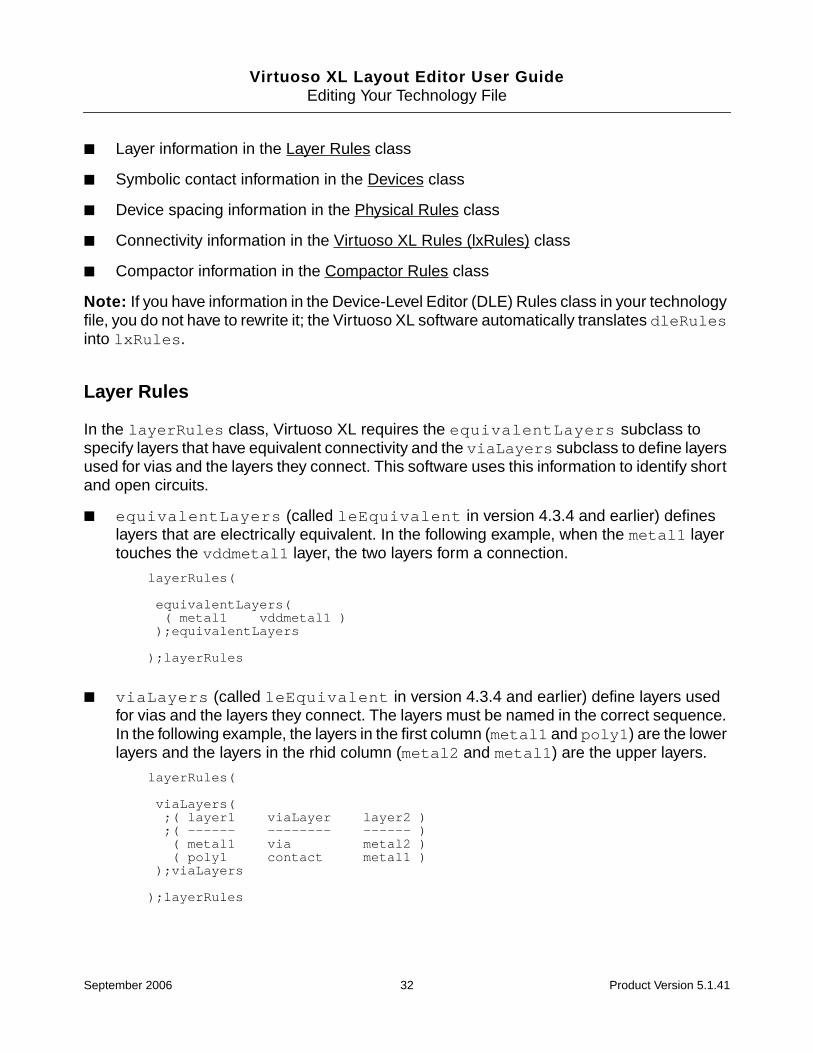
Virtuoso XL Layout Editor User GuideEditing Your Technology File
■ Layer information in the Layer Rules class
■ Symbolic contact information in the Devices class
■ Device spacing information in the Physical Rules class
■ Connectivity information in the Virtuoso XL Rules (lxRules) class
■ Compactor information in the Compactor Rules class
Note: If you have information in the Device-Level Editor (DLE) Rules class in your technologyfile, you do not have to rewrite it; the Virtuoso XL software automatically translates dleRulesinto lxRules.
Layer Rules
In the layerRules class, Virtuoso XL requires the equivalentLayers subclass tospecify layers that have equivalent connectivity and the viaLayers subclass to define layersused for vias and the layers they connect. This software uses this information to identify shortand open circuits.
■ equivalentLayers (called leEquivalent in version 4.3.4 and earlier) defineslayers that are electrically equivalent. In the following example, when the metal1 layertouches the vddmetal1 layer, the two layers form a connection.
layerRules(
equivalentLayers(( metal1 vddmetal1 ));equivalentLayers
);layerRules
■ viaLayers (called leEquivalent in version 4.3.4 and earlier) define layers usedfor vias and the layers they connect. The layers must be named in the correct sequence.In the following example, the layers in the first column (metal1 and poly1) are the lowerlayers and the layers in the rhid column (metal2 and metal1) are the upper layers.
layerRules(
viaLayers( ;( layer1 viaLayer layer2 );( ------ -------- ------ )( metal1 via metal2 )( poly1 contact metal1 )
);viaLayers
);layerRules
September 2006 32 Product Version 5.1.41

Virtuoso XL Layout Editor User GuideEditing Your Technology File
If you have contact and via layers defined as equivalent to their correspondinginterconnect layers, you can flatten contacts or draw new shapes to maintain or createconnectivity.
Important
If you use devices from different libraries for your design, the layer and connectivityinformation in the technology file for each library must be compatible.
Tip
Cadence recommends that you define and use symbolic vias for all of the requiredcut and layer combinations, including base layers. Doing so means that you do notneed viaLayer definitions for these cuts and layers. Use viaLayer definitionsonly if you want to connect flat shapes on polysilicon, contact or metal1 layerswithout using a symbolic via. For more information on defining symbolic vias, seeDevices.
Devices
In the Devices class, Virtuoso XL requires symbolic contact (symContactDevice)definitions for instances used as vias and for path stitching.
devices
symContactDevice(;( name viaLayer viaPurpose layer1 purpose1 layer2 purpose2; w l ( row column xPitch yPitch xBias yBias ) encByLayer1 encByLayer2; legalRegion )
( M2_M1 via drawing metal1 drawing metal2 drawing.6 .6 ( 1 1 1.8 1.8 center center ) .6 .6_NA_)
);symContact Device
);devicesevice
You need contact definitions if you want to
■ Place contacts using the Create – Contact command.
■ Perform path stitching (which automatically places contacts) using the Create – Pathcommand.
■ Perform path stitching with the routing commands.
Note: The mpu.tf file has sample contact definitions in the devices class.
September 2006 33 Product Version 5.1.41
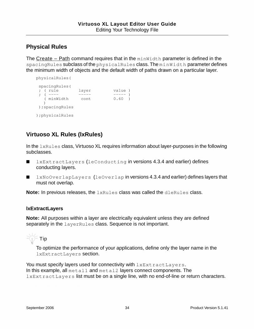
Virtuoso XL Layout Editor User GuideEditing Your Technology File
Physical Rules
The Create – Path command requires that in the minWidth parameter is defined in thespacingRules subclass of the physicalRules class. The minWidth parameter definesthe minimum width of objects and the default width of paths drawn on a particular layer.
physicalRules(
spacingRules(; ( rule layer value ); ( ---- ----- ----- )( minWidth cont 0.60 )
));spacingRules
);physicalRules
Virtuoso XL Rules (lxRules)
In the lxRules class, Virtuoso XL requires information about layer-purposes in the followingsubclasses.
■ lxExtractLayers (leConducting in versions 4.3.4 and earlier) definesconducting layers.
■ lxNoOverlapLayers (leOverlap in versions 4.3.4 and earlier) defines layers thatmust not overlap.
Note: In previous releases, the lxRules class was called the dleRules class.
lxExtractLayers
Note: All purposes within a layer are electrically equivalent unless they are definedseparately in the layerRules class. Sequence is not important.
Tip
To optimize the performance of your applications, define only the layer name in thelxExtractLayers section.
You must specify layers used for connectivity with lxExtractLayers.In this example, all metal1 and metal2 layers connect components. ThelxExtractLayers list must be on a single line, with no end-of-line or return characters.
Is this example correct?
September 2006 34 Product Version 5.1.41

Virtuoso XL Layout Editor User GuideEditing Your Technology File
lxRules(
lxExtractLayers(( metal1 metal2 ));lxExtractLayers
);lxRules
You must set lxExtractLayers for a layer before you can set lxNoOverlapLayersand equivalentLayers for that layer.
Important
In order for the abutment, folding, and chaining features to work correctly, you mustdefine the diffusion layers in the lxExtractLayers section.
Defining lxExtractLayers with Layer Purposes
Important
You should specify a layer-purpose pair in the lxExtractLayer section only whenyou need that layer-purpose pair to be treated differently from the other purposes forthat layer.
If you specify only the layer name in the lxExtractLayers section, then all purposes onthat layer are treated the same by the extractor. Consider the example below.
lxExtractLayers(( layer1 layer2 )
);lxExtractLayers
equivalentLayers(( ( layer1 purpose1 ) layer2 )
);equivalentLayers
In this example, layer1 purpose1 is equivalent to layer2 and layer1 purpose2is also equivalent to layer2. layer1 purpose2 is not listed in the equivalentLayerssection, but because layer1 is defined in the lxExtractLayers section, all purposesassociated with layer1 are used.
If you define the layer-purpose pair in the lxExtractLayers section, each layer-purposepair is treated differently by the extractor. You define the layer-purpose pairs in thelxExtractLayers section as shown below.
lxExtractLayers(( ( layer1 purpose1 ) ( layer1 purpose2 ) layer2 )
);lxExtractLayers
September 2006 35 Product Version 5.1.41

Virtuoso XL Layout Editor User GuideEditing Your Technology File
equivalentLayers(( ( layer1 purpose1 ) layer2 )
);equivalentLayers
Note: This works the same with lxNoOverlapLayers.
lxNoOverlapLayers
lxNoOverlapLayers specifies that two layers that must not overlap. In this example,when the poly layer touches the diff layer, Virtuoso XL reports an error.
lxRules(
lxNoOverlapLayers( ( poly diff ));lxNoOverlapLayers
);lxRules
Note: If you are working with a hierarchical design, you can set properties on instances atthe lower levels of the design to avoid false overlap and short markers.
The lxBlockOverlapCheck property, defined on a shape, instance, or instance master, tellsthe extractor not to check whether a nonoverlap layer of this shape or instance is touching anonoverlap layer at the current cellview level.
For example, if you define the lxBlockOverlapCheck property on a shape in cellview “A”,you will not see any markers when overlapping the shape with an instance. However, ifcellview “A” is placed inside cellview “B”, and a noOverlap layer is drawn over the shape incellview “A”, then a marker is displayed. This happens even though the shape in cellview “A”has the lxBlockOverlapCheck property defined.
The lxBlockExtractCheck property, defined on a shape, instance, or instance master, tells theextractor not to check the connectivity between this shape and others it touches.
For example, when you move a floating shape (i.e., a shape stamped on a net but with nolxStickyNet property or with lxStickyNet set to false) with thelxBlockExtractCheck property, the shape remains on its net after the move.
Compactor Rules
To use the Virtuoso compactor to compact your design, you need to include information aboutlayer-purposes in the compactorRules class.
■ The compactorLayers subclass defines the layer names and purposes used in thedesign.
September 2006 36 Product Version 5.1.41

Virtuoso XL Layout Editor User GuideEditing Your Technology File
compactorLayers(;( layer usage );( ----- ----- )( diff "diffusion" )( poly1 "conduction" )( metal1 "conduction" )( metal2 "conduction" )( metal3 "conduction" )( via "via" )( via2 "via" )( pwell "well" )( pimplant "implant" )( hardFence "hardFence" )( softFence "softFence" )( prBoundary "cellBoundary" ));compactorLayers
■ The symWires subclass specifies symbolic wires and how the compactor processesthem when it compacts a design.
symWires(
;( name layer [(impLayer impSpacing)] [(default min max)];[(legalRegion regionLayer)] [WLM] );( ---------------------------------------------------------------- )
( "poly1" ("poly1" "drawing") nil (.6 nil nil)nil 5.0 )
( "pdiff" ("diff" "drawing") (("pimplant" "drawing") .3) (.6 nil nil)( "outside" "pwell") 100.0 )
( "ndiff" ("diff" "drawing") nil (.6 nil nil)( "inside" "pwell") 100.0 )
( "metal1" ("metal1" "drawing") nil (.6 nil nil)nil 0.04 )
( "metal2" ("metal2" "drawing") nil (.6 nil nil)nil 0.02 )
( "metal3" ("metal3" "drawing") nil (1.2 nil nil)nil 0.02 )
);symWires
■ The symRules subclass checks enclosures between objects on different layers andspacings between objects on the same layer. The drc functions specify that rules applyonly to particular devices or objects on the same or different nets.
symRules(
; list of rulesdrc(("cont" "drawing" "M1_POLY1") ("diff" "drawing" "NTR") (sep < .6))drc(("cont" "drawing" "M1_POLY1") ("diff" "drawing" "PTR") (sep < .6))
);symRules
September 2006 37 Product Version 5.1.41

Virtuoso XL Layout Editor User GuideEditing Your Technology File
For more information on the compactorRules and symWires subclasses, see theTechnology File and Display Resource File SKILL Reference Manual.
For more information on using the Virtuoso compactor, see the Virtuoso CompactorReference Manual.
Sample Technology File
Virtuoso XL includes a sample technology file called mpu.tf that you can use as is orchange to meet the requirements of your design. The file contains data for a two-layer metalCMOS process and information about Virtuoso XL technology file requirements. To see thecontents of mpu.tf, type the following in a terminal window.
cd your_install_dir/tools/dfII/samples/techfile
more mpu.tf
where your_install_dir is the directory in which you store the Cadence software.
The mpu.tf technology file covers the following areas.
■ Differences between the pre-4.4 versions and later versions of the technology file
■ Layer definitions (layer numbers, purposes, priorities, and connectivity)
■ Symbolic devices (including symbolic contacts)
■ Physical rules, such as spacing rules (including minWidth) and ordered spacing rules
■ Electrical rules
■ Virtuoso XL-specific rules
■ Other application-specific rules
You must define this information in the technology files referenced by the design.
September 2006 38 Product Version 5.1.41
Virtuoso XL Layout Editor User Guide
3Preparing Your Connectivity Source
This chapter explains how to prepare a schematic or netlist connectivity source for yourdesign for generating, placing, and routing a layout with the Virtuoso® XL Layout Editor(Virtuoso XL).
This chapter covers the following topics.
■ Placing Design Elements on page 39
■ Using Design Variables on page 40
■ Using One-to-Many Mapping on page 42
■ Preparing a Library for use with Quick Cells on page 43
■ Using Properties on page 49
■ Preparing Pins on page 51
Placing Design Elements
You can use any schematic to generate a layout with Virtuoso XL. However, the process iseasier if you follow these guidelines when you create your schematic:
■ Place symbols of devices and pins in the schematic approximately where you want themto be in the layout. The Virtuoso XL Edit – Place As In Schematic command lets youplace layout devices and create pins in positions that correspond to the positions of theirschematic symbols.
■ Use consistent parameter defaults for comparable symbols
Virtuoso XL applies the parameters of the symbols to the layout devices.
September 2006 39 Product Version 5.1.41

Virtuoso XL Layout Editor User GuidePreparing Your Connectivity Source
Important
Virtuoso XL does not pass CDF parameters that are not evaluated (are not AELexpressions) and have cdfParamRec~>storeDefault=nil. These aremaster parameters and are expected to match for both schematic and layout master.Virtuoso XL does not pass them to the layout instance even when lxUseCell isused. If you require the parameters to be passed, set cdfParamRec->storeDefault to t for the schematic master parameters.
Note: When transferring information from the schematic to the layout, Virtuoso XL flattensthe schematic (expands schematic symbols into corresponding devices) if you provide a viewlist or a stop list to show Virtuoso XL which view of the lower-level instances to use.
Virtuoso XL also supports the use of
■ Design variables
■ One-to-many mapping
■ Many-to-many and many-to-one mapping
If you are preparing a hierarchical design, you also need to make sure the symbol view ofeach top-level design element is mapped to the correct layout view of the correspondinglayout element for generating the layout. For more information, see “Hierarchical Extraction”on page 298.
Using Design Variables
You can use the following design variables with Virtuoso XL.
■ Netlist Processor Expressions
■ Analog Expression Language Expressions
■ Simulation Design Variables
Netlist Processor Expressions
Netlist Processor (NLP) expressions are properties that specify parameter values. Theseexpressions are used by the Open Simulation System (OSS) in netlisting.
For more information, see the Open Simulation System Reference.
September 2006 40 Product Version 5.1.41

Virtuoso XL Layout Editor User GuidePreparing Your Connectivity Source
Analog Expression Language Expressions
Analog Expression Language (AEL) expressions, such as iPar and pPar, define the valueof a parameter as a function of other instance parameters or parameters passed from otherlevels of hierarchy. If you specify the value of a parameter using an AEL expression, theparameter
■ Must be defined in the component description format (CDF) for the cell of which thesymbol is a view.
■ Must be a string for which parseAsNumber and parseAsCEL properties are set to t.
■ Must not have a CDF callback (because the evaluation of the expression does not triggerthe execution of the callback).
If Layout XL detects a parameter value defined with iPar, pPar, or other AEL expressionsnot defined in the CDF, you see a warning in a message box.
Netlisting Mode
To ensure that CDF parameters are always evaluated correctly, make sure that theCDS_Netlisting_Mode shell environment variable is set to Analog.
To set CDS_Netlisting_Mode,
➤ Type the following commands in the CIW.
setShellEnvVar("CDS_Netlisting_Mode=Analog")
cdsSetNetlistMode()
To check which mode is currently set,
➤ Type the following command in the CIW.
cdsGetNetlistMode()
For more information on CDS_Netlisting_Mode, see “Customizing the SimulationEnvironment” in the Open Simulation System Reference.
For more information on AEL expressions, see “Scope of Parameters” in Chapter 3 of theCadence Analog Circuit Design Environment User Guide.
September 2006 41 Product Version 5.1.41
Virtuoso XL Layout Editor User GuidePreparing Your Connectivity Source
Simulation Design Variables
When you use simulation design variables to specify the value of a parameter in the circuit,Virtuoso XL uses the value last saved during the simulation of the circuit as the value for thelayout implementation.
For more information about simulation design variables, see “Design Variables andSimulation” in Chapter 3 of the Cadence Analog Circuit Design Environment UserGuide.
Using One-to-Many Mapping
You can implement one-to-many mapping in Virtuoso XL designs using
■ Iterated Instances and Bus Pins
■ The Multiplication Factor (mfactor)
■ The Series-connected Factor (sfactor)
■ One-to-Many Assignment with Update Device Correspondence
Iterated Instances and Bus Pins
You can use iterated instances and bus pins in a schematic with Virtuoso XL. Use of iteratedinstances enables one-to-many mapping between pins and devices in the schematic andmultiple instances of the pins and devices in the layout.
Note: For more information on iterated instances, see “Adding Instances Using an IterativeExpression” in the Virtuoso Schematic Editor User Guide.
For example, the figure below shows
■ Bus pin SEL<0:1> in the schematic mapped to bus pins SEL<0> and SEL<1> in thelayout.
September 2006 42 Product Version 5.1.41
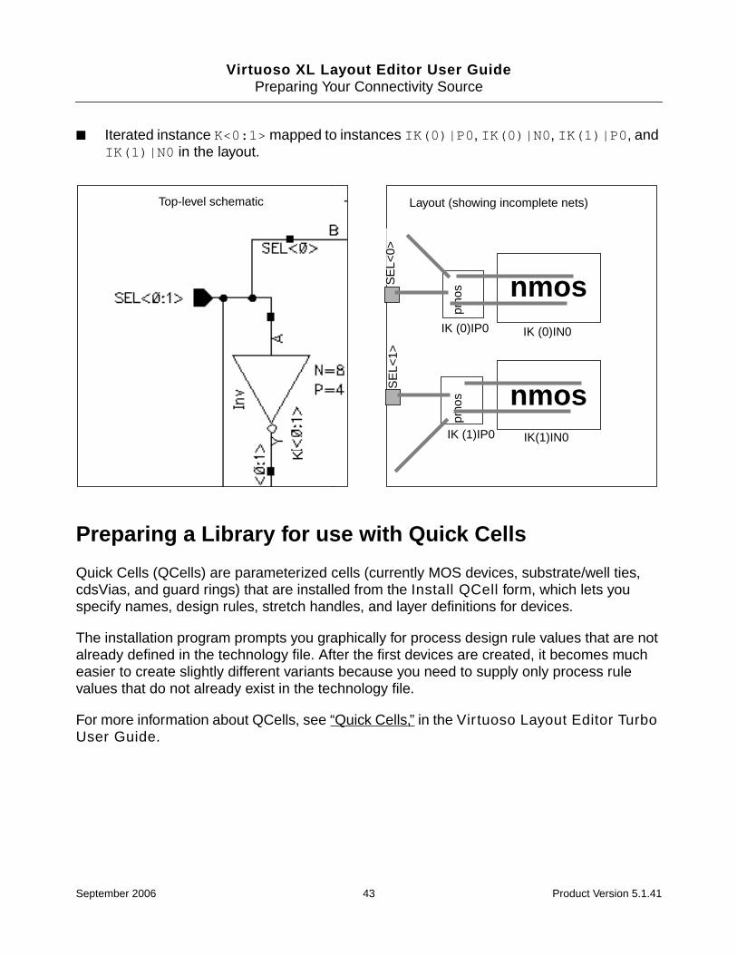
Virtuoso XL Layout Editor User GuidePreparing Your Connectivity Source
■ Iterated instance K<0:1> mapped to instances IK(0)|P0, IK(0)|N0, IK(1)|P0, andIK(1)|N0 in the layout.
Preparing a Library for use with Quick Cells
Quick Cells (QCells) are parameterized cells (currently MOS devices, substrate/well ties,cdsVias, and guard rings) that are installed from the Install QCell form, which lets youspecify names, design rules, stretch handles, and layer definitions for devices.
The installation program prompts you graphically for process design rule values that are notalready defined in the technology file. After the first devices are created, it becomes mucheasier to create slightly different variants because you need to supply only process rulevalues that do not already exist in the technology file.
For more information about QCells, see “Quick Cells,” in the Virtuoso Layout Editor TurboUser Guide.
K
Top-level schematic
SE
L<0>
SE
L<1>
pmos
pmos
IK (0)IP0 IK (0)IN0
IK(1)IN0IK (1)IP0
Layout (showing incomplete nets)
nmos
nmos
September 2006 43 Product Version 5.1.41

Virtuoso XL Layout Editor User GuidePreparing Your Connectivity Source
Creating a New Library to Use With QCells
Creating the Library
1. Choose the technology file to be loaded into the new library.
❑ Use the Tools – Technology File Manager command to dump out a technologyfile from an existing library.
❑ Use an existing ASCII technology file.
2. Remove form the technology file any reference to layout cellviews from another library.
Caution
When you install Quick Cells into a new or existing technology library, thesoftware either creates a new layout view or overwrites an existing layout.To preserve the original versions, rename the existing NMOS and PMOSlayout cellviews to a different view name. For example, renamenmoslayout to nmoslayout.orig.
3. In the CIW, select Tools – Technology File Manager and click the New button.
4. Specify a name for the new technology library, turn on the Load ASCII Technology Fileoption, and specify an ASCII technology file.
5. Click OK to create the new library.
Copying Symbols
1. Decide which NMOS and PMOS symbols you want to copy from an existing library.
2. In the CIW, select Tools – Library Manager and select the symbols that you want tocopy into the new library.
3. In the Library Manager choose Edit – Copy and change the To Library field to yournew library name.
4. Deselect the Copy All Views checkbox in order to make the Views To Copy fieldeditable. If there are any layout views listed in this field, remove them. You will create yourlayouts by installing QCells instead.
5. The Copy Problems dialog box appears. Click Fix Errors and select UpdateInstances. Next select New Copy then click OK. The cell is copied to your new library.
6. Repeat the steps for the other symbols.
September 2006 44 Product Version 5.1.41

Virtuoso XL Layout Editor User GuidePreparing Your Connectivity Source
Remastering Symbol Instances
The names of the schematic symbols must match the names of the MOS devices you createusing Quick Cells. If you know the names of the MOS devices you will create, complete thefollowing steps.
Important
If the symbol name does not match the corresponding MOS device, then you mustadd the lxUseCell property to the symbol. For more information, see “Setting thelxUseCell Property” on page 45.
1. Choose File – Open.
2. Choose the name of the schematic you have copied.
3. Choose Edit – Search – Replace.
4. In the Search For field select instName from the cyclic field and type in the name of thecurrent symbol.
5. In the Replace With field select instName from the cyclic field and type in the name ofthe MOS device to be created.
6. Click Replace.
Setting the lxUseCell Property
Virtuoso XL places the layout with the same cell name as the symbol in the schematic. If youdo not want the name to be the same, you must add the lxUseCell property to thecorresponding symbol in the schematic. You do this using the Edit Object Properties form.
Caution
Cadence recommends that you do NOT set the lxUseCell property formixed-signal designs. For digital designs, the cells can be in differentlibraries. For mixed-signal designs, you must use a CDF to define theparameters for the devices. Therefore, the symbol and layout must be inthe same library and cell.
1. In the schematic, select the symbol for which you want to set the property.
2. Choose Edit – Properties – Objects.
3. Click the Add button to display the Add Property form.
September 2006 45 Product Version 5.1.41
Virtuoso XL Layout Editor User GuidePreparing Your Connectivity Source
4. Specify the Name of the cell, the Type as string, and the Value as the library and cellname.
Installing Qcells
1. Choose Tools – Technology File Manager and click QCell.
2. Select the technology library from the pull-down list.
3. Specify the name of the MOS device in the Name field.
4. Specify Diffusion, Gate Poly, Contact, and Metal layers.
5. Click Rules to display the Rules Browser.
The Rules Browser provides a graphical representation of a generic device, and thelayers that you specified in the Layers section of the Install QCell form.
6. The rules are taken from the technology file attached to your library. If there are any rulesmissing, add them in the Rules section of the Install QCell form.
When you position the cursor in the rules fields, the Rules Browser window displays anarrow to show the physical area where the corresponding rule applies.
7. Choose Stretch Handles and turn on the Select All option or just the stretch handlesthat you want to use.
8. Choose Parameter Defaults. The form is partially grayed out until you specify theComponent Class.
9. Set the Abutment Class to either NMOS or PMOS depending on whether you are creatingan NMOS or PMOS device. Alternatively, you can specify a user-defined abutment class.
Note: The abutment class is the device name.
10. Set the Component Class to either NMOS or PMOS.
The information from the Component Class field updates the component type for thatdevice in the Edit Component Types form. You can verify that the device has beenupdated in the Component Type form after you click Apply or OK.
Note: The purpose of component types is to identify the NMOS and PMOS transistorcells and set their parameters for device chaining and folding.
11. Specify the MOS Type. The entire form is now editable.
The CDF Parameters section updates with default CDF parameters or defined CDF ifpresent.
September 2006 46 Product Version 5.1.41
Virtuoso XL Layout Editor User GuidePreparing Your Connectivity Source
Important
You can edit the Parameter Defaults or units in the Install QCell form, but youcannot change the parameter types once they have been applied. Use Tools - CDF- Edit command to change the component parameters.
12. Set the Unit cyclic field to either meter or micron. The CDF unit meter =lengthMetric and micron = don’t use.
Caution
You cannot reset or edit the Unit field.
13. Set the values for w, l, and fingers as needed (e.g., w=2u, l=.18u, fingers=1).
14. Click Apply to create the QCell.
15. Repeat the step for the other device (NMOS or PMOS) that needs to be created.
16. Save the new technology library.
Setting Units Correctly for QCells
If the symbol view corresponding to the QCell have dimension units defaulting tolengthMetric (i.e., meter rather than micron), you must enter the values in the schematicwith the appropriate extension (e.g., 1u or 1000n or 1e-06 instead of simply 1, which wouldbe interpreted as 1M).
The same applies to setting the folding threshold in the various Virtuoso XL forms. However,using the Property Editor form to edit QCells offers you the flexibility to enter values both withand without the unit extension.
Note: Typically most PDKs have callbacks to prevent you from entering a value such as thiserroneously in the schematic.
Using an Existing Library
If you are using an existing technology library, consider the following.
■ The symbols must contain CDF parameters.
■ In reference libraries, the component type is not updated unless the reference library isadded to the compTypeRefLibs environment variable in the .cdsenv file. Inyour .cdsenv file add
September 2006 47 Product Version 5.1.41

Virtuoso XL Layout Editor User GuidePreparing Your Connectivity Source
layoutXL compTypeRefLibs string (refLibName)
■ Rename existing NMOS and PMOS layout cellviews to a different view name. Forexample, rename nmoslayout to nmoslayout.orig. When you install the QCells,they do not overwrite the existing layout cellview correctly. You can also use thelxUseCell property. For more information, see “Setting the lxUseCell Property” onpage 45.
■ If layout devices are being created directly from the technology file, remove or renamethem.
Inserting a QCell Device
When you insert a QCell device into your design, you must run Connectivity – Update –Device Correspondence to update the connectivity. If you do not update the devicecorrespondence, the QCell you inserted will have no connectivity.
1. Choose Create – Device and click on the icons to specify the type of device.
2. Move the cursor into the layout window to place the device in the design.
3. Choose Connectivity – Update – Device Correspondence. The schematic windowprompts you to click on one or more symbols.
For more information on this command, see “Updating Device Correspondence” onpage 436.
4. In a schematic window, click on the symbols whose connectivity you want to update inthe layout.
5. With the cursor in the schematic window, press Return.
The layout window prompts you to select one or more corresponding objects in the layoutwindow.
6. In the layout window, click on the object or objects to associate with the symbol.
7. With the cursor in the layout window, press Return.
Important
The correspondence is defined only when you press Return.
A message similar to the one below is displayed in the CIW saying that the connectionhas been made.
Virtuoso XL: Instance ’I1’ in cellView ’overview amp1 layout’ is renamed’|R21’.
September 2006 48 Product Version 5.1.41

Virtuoso XL Layout Editor User GuidePreparing Your Connectivity Source
Using Layout Optimization
The Optimize tool facilitates the hand layout of cells. For more information, see “LayoutOptimize”, in the Virtuoso Layout Editor Turbo User Guide.
Using Properties
Before Virtuoso XL can create a layout from a schematic, you must create a layout device forevery symbol in the schematic. The layout master cell of a device or contact can be a fixedcell, a parameterized cell (pcell), or a device or contact defined in the technology file.
Pcells are often the most effective because you can assign the dimensions of the device atlayout generation and vary the sizes of a contact each time you place the cell. For moreinformation about pcells, see the Virtuoso Parameterized Cell Reference Manual.
Note: The default values for any given property must be the same in the schematic and thelayout. If the default value of a property differs between the two cellviews, and the propertyhas a value of storeDefault=nil, then when you invoke the Design – Gen FromSource command, the layout instance is not updated (i.e., the CDF default of the layout isused). This can lead to a parameter mismatch between the layout and the schematic.
Property Definitions
The properties used by Virtuoso XL are described below.
lxUseCell
Add to the symbols of device cells to specify which cell (orlibrary and cell, if a you want to use a cell from different library)to use for the layout instance.
lvsIgnore, ignore, ignoreNames, nlAction
Add to the symbols in the schematic to prevent them from beingplaced in the layout.
lxParamsToIgnore
Blocks unwanted parameters.
lxRemoveDevice
Ignores parasitic devices.
lxViewList, lxStopList
September 2006 49 Product Version 5.1.41

Virtuoso XL Layout Editor User GuidePreparing Your Connectivity Source
Note: The lxParamsToIgnore, lxViewList, and lxStopList properties havedefault values that are used when properties are not found. The corresponding environmentvariable names are paramsToIgnore, viewList, and stopList. Their values are allstrings containing words separated by spaces.
To use Virtuoso XL to create complex devices and to generate your own internal net prefixes,add the following properties.
Add to the symbols of device cells in hierarchical designs tospecify the layout views to use.
lxCombination
Builds a complex set of devices consisting of series (sfactor)and parallel (mfactor) connections.
Note: The lxCombination property supports a maximum oftwo terminal devices.
lxNetNamePrefix
Adds a prefix to internal nets in the layout.
lxBlockExtractCheck
Blocks the connectivity of shapes that touch.
lxBlockOverlapCheck
Prevents the extractor from checking whether a nonoverlaplayer of this shape or instance is touching a nonoverlap layer atthe current cellview level.
lxMfactorSplit
Controls whether Virtuoso XL places a schematic device withthe mfactor property as multiple devices in the layout.
lxRounding
Prevents folded devices from becoming off-grid.
lxSeriesTerms
Add the property to understand the connectivity of the deviceswith sfactor > 1 and instance terminals >2.
mfactor
September 2006 50 Product Version 5.1.41

Virtuoso XL Layout Editor User GuidePreparing Your Connectivity Source
Preparing Pins
For connectivity assignment tracing and cross-probing to work correctly in Virtuoso XL, thepins and pin names in the layout cellview of a device must match those in the correspondingschematic symbol.
Defines a one-to-many parallel relationship between a device ina schematic and multiple devices in the layout.
sfactor
Defines a one-to-many relationship between a device in aschematic and multiple instances in a series connection in thelayout.
permuteRule
Makes the instance pins or terminals of a device permutable.
vxlInstSpacingDir
Assigns automatic spacing to pins of instances.
vxlInstSpacingRule
Defines a spacing offset when pins are on a different net.
cdsTerm(C)
cdsTerm(E)
cdsTerm(B)
CBE
G
G
D S
gnd!
analoglib library style pin layout basic library style pin layout
analoglib library style pin symbol basic library style pin symbol
G
G
D S
September 2006 51 Product Version 5.1.41

Virtuoso XL Layout Editor User GuidePreparing Your Connectivity Source
Extra Pins in the Symbol or Layout Views
Layout XL cannot maintain connectivity for any extra pins in the symbol view because thereis no corresponding pin for the device in the layout view.
Layout XL does maintain connectivity for extra pins whose names are global nets (forexample, vdd!) in the layout view. It also maintains connectivity for any extra pins in thelayout whose connectivity is defined by inherited connections. The inherited connection canbe defined relative to the layout instance itself or relative to the schematic hierarchy that endswith the schematic instance corresponding to that layout instance.
To determine which net to connect to such a pin, Layout XL first tries to resolve the inheritednet expression on the layout pin. If there is no net expression, the software looks for aproperty named either sub, sub_inh, or bn on the layout master, uses the value of theproperty as the substrate net name, and connects the extra terminal to that net.
Note: Do not place pins where you do not want to make a connection; for example, on a polylayer that covers the gate area of a FET. For more information, see “Adding Pins to a Layout”on page 199.
External Connections
You can also define pins to be connected externally to the design.
Note: The commands in the Connectivity – Define Pins submenu let you connect pins infour different ways.
■ Must Connect connects selected pins in a net externally at a higher level of thehierarchy.
■ Strongly Connected connects selected pins within the device. By default, pins areconnected internally (strongly).
■ Weakly Connected connects selected pins in a limited external connection to avoidspecific internal connections (typically ones with high-resistance paths).
■ Pseudo Parallel Connect connects selected instance terminals on the same net withinan instance as though they were connected externally; that is, they are defined as aconnection but need never be physically connected.
For more information about must-connect pins, strongly connected pins, weakly connectedpins, and pseudo-parallel connected pins, see the “Using Connectivity” section of theVirtuoso Layout Editor User Guide.
To permute pins see “permuteRule” on page 789.
September 2006 52 Product Version 5.1.41

Virtuoso XL Layout Editor User GuidePreparing Your Connectivity Source
If you are using parameterized cells pcells and want to give them the capability for abutment(overlapping pins to create a connection), see “Device Abutment” on page 71.
September 2006 53 Product Version 5.1.41

Virtuoso XL Layout Editor User GuidePreparing Your Connectivity Source
September 2006 54 Product Version 5.1.41
Virtuoso XL Layout Editor User Guide
4Setting Up the Virtuoso XL Environment
This chapter explains how to set up your Virtuoso® XL Layout Editor (Virtuoso XL) designenvironment to suit your preferences and work habits. You can use design variables tochange the value of many aspects of your design environment either for an individual designsession or permanently (until you change the value of a variable).
This chapter discusses the following topics,
■ Setting Up Your Desktop on page 56
❑ Customizing Your Desktop Layout on page 56
❑ Using Multiple Cellviews on page 57
❑ Printing to the Command Interpreter Window on page 57
■ Changing Display Colors on page 58
■ Using Bindkeys on page 61
❑ Displaying Bindkeys on page 61
❑ Loading Bindkeys on page 62
■ Setting Environment Variables on page 62
■ Using Setup Files or the CIW on page 64
For information on Virtuoso XL forms, see “Online Forms” on page 65.
September 2006 55 Product Version 5.1.41
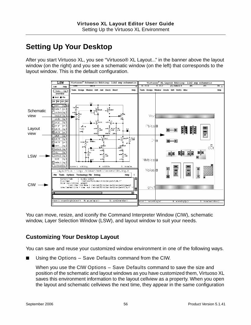
Virtuoso XL Layout Editor User GuideSetting Up the Virtuoso XL Environment
Setting Up Your Desktop
After you start Virtuoso XL, you see “Virtuoso® XL Layout...” in the banner above the layoutwindow (on the right) and you see a schematic window (on the left) that corresponds to thelayout window. This is the default configuration.
You can move, resize, and iconify the Command Interpreter Window (CIW), schematicwindow, Layer Selection Window (LSW), and layout window to suit your needs.
Customizing Your Desktop Layout
You can save and reuse your customized window environment in one of the following ways.
■ Using the Options – Save Defaults command from the CIW.
When you use the CIW Options – Save Defaults command to save the size andposition of the schematic and layout windows as you have customized them, Virtuoso XLsaves this environment information to the layout cellview as a property. When you openthe layout and schematic cellviews the next time, they appear in the same configuration
Schematicview
Layoutview
LSW
CIW
as
Virtuoso® Schematic Editing: lib2 amp schematic Virtuoso® XL Layout Editing: lib2 amp schematicLSW
September 2006 56 Product Version 5.1.41
Virtuoso XL Layout Editor User GuideSetting Up the Virtuoso XL Environment
as they had when you saved them. The command sends the LSW and the CIW windowsize and location information to the .cdsenv file.
For information on this command, see “Saving and Recalling Default Values” in theCadence Design Framework II User Guide.
■ By adding the appropriate environment variables to your .cdsenv file; for example, asshown in the example below.
To prevent Virtuoso XL from rearranging or resizing windows from the way you havearranged them, add the following line to the .cdsenv file:
envSetVal(“layoutXL” “autoArrange” ‘boolean nil)
For more information, see “Environment Variables” on page 470.
Note: If you save your current window positions and form settings to a file otherthan .cdsenv (for example, .envFileName), you can restore them by adding thefollowing command to your .cdsinit file or typing it in the CIW.
envLoadFile("layoutXL" ".envFileName")
Using Multiple Cellviews
If you open multiple cellviews in Virtuoso XL, the second and subsequent sets of windows arenot automatically configured in the same way as the first set.
You can open more than one pair of schematic-layout windows in Virtuoso XL and work oneach pair independently.
■ If you open a schematic and two copies of the same layout, the Check, Probe, andUpdate commands in the Connectivity submenu apply to both layouts.
■ If you open a schematic and two different layouts, the Check, Probe, and Updatecommands in the Connectivity submenu apply only to the layout from which youselected the command.
Printing to the Command Interpreter Window
To print process information to the CIW instead of to a separate Virtuoso XL Info window, addthe following command to your .cdsenv file or type it in the CIW
envSetVal(“layoutXL” “infoWindow” ‘boolean nil)
September 2006 57 Product Version 5.1.41
Virtuoso XL Layout Editor User GuideSetting Up the Virtuoso XL Environment
Changing Display Colors
You can change the colors and characteristics of the entry layers that Virtuoso XL commandsuse for display purposes. You can change the display layers Virtuoso XL uses for the followingcommands:
■ The Show Incomplete Nets command uses the y0 through y9 entry layers to showflight lines.
■ The Connectivity – Check – Against Source command uses the hilite drawing9entry layer to identify missing devices
■ The Connectivity – Probe command uses the hilite drawing through hilite drawing9entry layers to probe pins, nets, and devices
■ The Highlight command for placement constraints uses the annotate drawing3 entrylayer to highlight in the layout the components bound by a placement constraint
■ The Pick from Schematic command uses the hilite drawing1 layer to highlightschematic symbols
Editing Entry Layers
Although you can edit these layers from the LSW, it is not recommended. To edit these layers,
1. Add the layers to the LSW as valid layers. Valid layers are those you use for creatinglayout shapes.
2. In the CIW, choose Tools – Display Resource Manager.
3. In the Display Resources Tool Box, click Edit.
The Display Resource Editor window appears.
September 2006 58 Product Version 5.1.41

Virtuoso XL Layout Editor User GuideSetting Up the Virtuoso XL Environment
4. Click All, so that you can see all of the available layers (not just the ones you havedefined as drawing layers).
5. In the Layers column, choose the name of the layer to change.
6. Turn on the Fill Style, Fill Color, Outline Color, Stipple, and Line Style options youwant to use for that layer.
7. Click Apply.
The next time you use a command that displays the layer you changed, the color orpattern changes in the design window.
Click on All
September 2006 59 Product Version 5.1.41
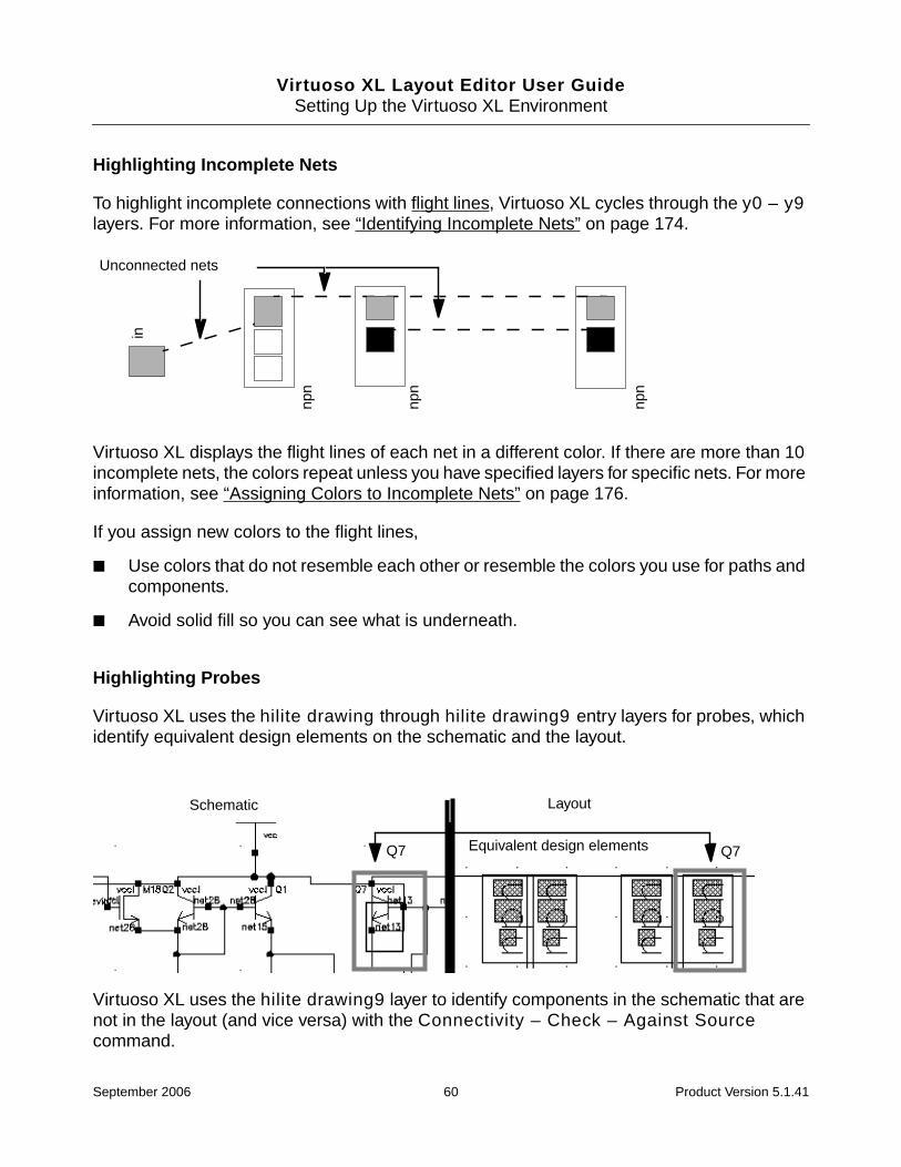
Virtuoso XL Layout Editor User GuideSetting Up the Virtuoso XL Environment
Highlighting Incomplete Nets
To highlight incomplete connections with flight lines, Virtuoso XL cycles through the y0 – y9layers. For more information, see “Identifying Incomplete Nets” on page 174.
Virtuoso XL displays the flight lines of each net in a different color. If there are more than 10incomplete nets, the colors repeat unless you have specified layers for specific nets. For moreinformation, see “Assigning Colors to Incomplete Nets” on page 176.
If you assign new colors to the flight lines,
■ Use colors that do not resemble each other or resemble the colors you use for paths andcomponents.
■ Avoid solid fill so you can see what is underneath.
Highlighting Probes
Virtuoso XL uses the hilite drawing through hilite drawing9 entry layers for probes, whichidentify equivalent design elements on the schematic and the layout.
Virtuoso XL uses the hilite drawing9 layer to identify components in the schematic that arenot in the layout (and vice versa) with the Connectivity – Check – Against Sourcecommand.
npn
npn
Unconnected nets
npn
in
Q7Equivalent design elementsQ7
Schematic Layout
September 2006 60 Product Version 5.1.41

Virtuoso XL Layout Editor User GuideSetting Up the Virtuoso XL Environment
If you change the colors of the hilite drawing layers,
■ Use thick lines so you can see device pins.
■ Use bright colors to make probes and highlights easy to find.
Tip
Do not make the hilite drawing layer and the hilite drawing2 layer solid fillbecause these layers are used to indicate selected components and to manipulateshapes.
Using Bindkeys
Bindkeys, also called function keys, are keyboard macros that assign a menu command to akey you choose from the keyboard. When your cursor is in the layout window, you can use allof the bindkeys that are loaded for the applications you are running.
Displaying Bindkeys
To display the list of bindkeys for Virtuoso XL, follow these steps.
1. From the CIW, choose Options – Bindkey.
The Key or Mouse Binding form is displayed.
2. In the Application Type Prefix cyclic field, choose Layout.
3. Click Show Bind Keys.
A text window displays the layout editor bindkeys and commands.
September 2006 61 Product Version 5.1.41
Virtuoso XL Layout Editor User GuideSetting Up the Virtuoso XL Environment
Loading Bindkeys
You can find a list of default bindkeys for Virtuoso XL at the following location:
your_install_dir/samples/local/lxBindKeys.il
where your_install_dir is the top directory in which you store Cadence® software.
To load this file of bindkey definitions every time you run Virtuoso XL, add the following lineto your .cdsinit file.
load(prependInstallPath("samples/local/lxBindKeys.il"))
Setting Environment Variables
Using the Layout XL Options Form
Environment variables control the values of Virtuoso XL options. You can set someVirtuoso XL environment variables in the individual options forms for Virtuoso XL commands.You can set other Virtuoso XL environment variables using the Layout XL Options form.
You must set the options relating to initialization (Show All Incomplete Nets and AutoArrange Windows) on the Layout XL Options form before you start your design session. Thevalues you enter for these options in the current session take effect the next time you startVirtuoso XL. Changes made to other values take effect as soon as you click OK or Apply. Toavoid having to restart the session, set these values in your .cdsenv or .cdsinit file. Formore information, see “Using Setup Files or the CIW” on page 64.
Not all the Virtuoso XL environment variables are available through forms. You can set thevalue of environment variables not available on forms in your .cdsenv or .cdsinit file.
Important
For a list of all the Virtuoso XL environment variables and their values, see“Environment Variables” on page 470.
To set environment variables using the Layout XL Options form, follow these steps.
1. From the layout window, choose Options – Layout XL.
September 2006 62 Product Version 5.1.41

Virtuoso XL Layout Editor User GuideSetting Up the Virtuoso XL Environment
The Layout XL Options form is displayed.
September 2006 63 Product Version 5.1.41
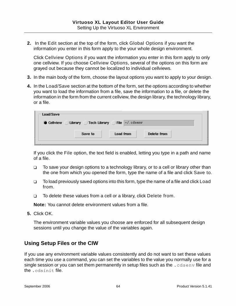
Virtuoso XL Layout Editor User GuideSetting Up the Virtuoso XL Environment
2. In the Edit section at the top of the form, click Global Options if you want theinformation you enter in this form apply to the your whole design environment.
Click Cellview Options if you want the information you enter in this form apply to onlyone cellview. If you choose Cellview Options, several of the options on this form aregrayed out because they cannot be localized to individual cellviews.
3. In the main body of the form, choose the layout options you want to apply to your design.
4. In the Load/Save section at the bottom of the form, set the options according to whetheryou want to load the information from a file, save the information to a file, or delete theinformation in the form from the current cellview, the design library, the technology library,or a file.
If you click the File option, the text field is enabled, letting you type in a path and nameof a file.
❑ To save your design options to a technology library, or to a cell or library other thanthe one from which you opened the form, type the name of a file and click Save to.
❑ To load previously saved options into this form, type the name of a file and click Loadfrom.
❑ To delete these values from a cell or a library, click Delete from.
Note: You cannot delete environment values from a file.
5. Click OK.
The environment variable values you choose are enforced for all subsequent designsessions until you change the value of the variables again.
Using Setup Files or the CIW
If you use any environment variable values consistently and do not want to set these valueseach time you use a command, you can set the variables to the value you normally use for asingle session or you can set them permanently in setup files such as the .cdsenv file andthe .cdsinit file.
September 2006 64 Product Version 5.1.41
Virtuoso XL Layout Editor User GuideSetting Up the Virtuoso XL Environment
To set environment variables for a single session, do one of the following.
■ Include envSetVal( ) in any other Cadence SKILL file you load.
■ Type envSetVal( ) in the CIW.
For more information on using envSetVal( ), see “About the Command InterpreterWindow” in the Virtuoso Layout Editor User Guide.
To set environment variables permanently, do one of the following.
■ Include the environment variables in the .cdsenv file in your home directory; forexample,
layoutXL alignApplySeparation boolean t
■ Include envSetVal( ) in your .cdsinit file
For example, to set the Virtuoso XL alignApplySeparation variable (which forcesVirtuoso XL to separate aligned components by a separation factor you supply), type thefollowing in the CIW or include it in a setup file.
envSetVal("layoutXL" "alignApplySeparation" 'boolean t)
To determine the current value of any Virtuoso XL environment variable, type the following inthe CIW.
envGetVal("layoutXL" "alignApplySeparation" 'boolean)
For more information on the .cdsenv and .cdsinit files, see “Setting Layout EditorDefaults” in the Virtuoso Layout Editor User Guide.
Online Forms
Layout XL Options
Edit
Global Options applies the values specified in the form to the cellview currently beingedited and all other views of the current cell.
Cellview Options applies the values specified in the form only to the cellview currentlybeing edited.
Connectivity lets you specify whether the connectivity extractor is enabled and whatmarkers it displays in the layout window. The settings in this section control only the currenttop-level cellview; they do not control lower level cellviews.
September 2006 65 Product Version 5.1.41

Virtuoso XL Layout Editor User GuideSetting Up the Virtuoso XL Environment
Connectivity Extractor switches on connectivity extraction. When the extractor isturned off, the Connectivity – Show Incomplete Nets command is disabled.
Extract Connectivity to Level sets the level at which hierarchical extractionstops.
Show Weak-Connect Violations toggles the display of top-level weak-connectviolation markers in the current cellview. Note that the extractor shows onlyviolations at the current top level, irrespective of the value you set for ExtractConnectivity to Level.
Show Must-Connect Violations toggles the display of must-connect violationmarkers in the current cellview. Note that the extractor shows only violations at thecurrent top level, irrespective of the value you set for Extract Connectivity toLevel.
Important
If you change the Extract Connectivity to Level, Show Weak-ConnectViolations, or Show Must-Connect Violations options, connectivity extraction istriggered right away and any changes are reflected immediately in the layoutwindow.
Cross Selection turns on cross-selection between the layout and schematic. When youselect a component in the layout, the corresponding component is selected in theschematic and vice versa.
Auto Abutment turns on automatic abutment, which abuts prepared transistors so thatthey can share pins.
Auto Space turns on automatic spacing, which allows components with the propertiesvxlInstSpacingDir and vxlInstSpacingRule to be spaced automatically according to thevalues specified in the properties.
Auto Permute Pins turns on automatic pin permutation during manual routing orediting. For more information, see “permuteRule” on page 789.
Constraint Assisted Move And Stretch turns on the constraint-assisted move andstretch capability.
Verification
■ Show Parameters to Ignore lists the parameters that are ignored by the Update –Check Against Source command.
The following parameters are always ignored.
September 2006 66 Product Version 5.1.41

Virtuoso XL Layout Editor User GuideSetting Up the Virtuoso XL Environment
dleIgnoredParams dleSchExtractPath dleStopList dleUseCellinstancesLastChanged instNamePrefixlxIgnoredParams lxIgnoreParamsForCAS lxMFactorNumlxParamsToIgnore lxParamsToIgnoreForChecklxPlacementStatus lxStopList lxTimeStamp lxUseCellmaskLayoutViewName pin# posi
Show Properties Used To Ignore Objects lists the properties that cause pins andinstances to be ignored during the Connectivity – Check – Against Sourcecommand. Any object with one of the listed properties set to t is ignored during theseoperations.
The following properties are always ignored.
ignore lvsIgnore nlAction
Add lets you add to the list a parameter or property name you have typed into thetext field.
Remove lets you remove parameters or properties selected in the list box.
Inherited from Generation lists the parameters or properties that are inherited fromthe list defined for generation. Parameters and properties ignored for generation arealways ignored for verification. To change this list, you need to edit it in the Generationgroup box.
Tolerance specifies the relative tolerance the Connectivity – Update – LayoutParameters command uses to compare values between the layout and the schematic.
If | (a/b) - 1.0 | < e then the parameters are considered equal, where a is sourceparameter value, b is the layout parameter value, and e is the Tolerance. The default ofe is 1e-6.
Ref Libs lists the reference libraries for which component types can be defined in the EditComponent Types form.
Device Folding
Generate Minimal Folding creates the minimum number of folded devices. If thisoption is turned off, then an odd number of folded devices is created. For example, it addsone finger if the device width divided by finger maximum width yields an even number.
Retain Instance Orientation preserves the device orientation when running the Edit– Folding or Design – Gen From Source commands with only folding switched on.When the Transistor Chaining option is also turned on, the chain orientation is alwayswith the gates in a vertical position.
pCell fingering Names specifies parameter names that define pcell gate fingering.Folding and instance fingers are incompatible and this option is used to filter out those
September 2006 67 Product Version 5.1.41

Virtuoso XL Layout Editor User GuideSetting Up the Virtuoso XL Environment
instances when folding. If you do not set the names correctly, it might result in abutmentfailures for even-fingered devices and folding.
Update Parameter specifies how the Connectivity – Update – Layout Parameterscommand updates folded devices.
No Change folded devices will not be updated.
Equalize uses the updated schematic width to produce fingers of equal width. Thenumber of fingers does not change, only the width of each finger.
Distribute uses the updated schematic width and distributes the width amongst allthe fingers. The number of fingers does not change, only the width of each finger.
Generation
Show Traverse Hierarchy Views lists the views included in the view list whendescending a hierarchical design.
Show Layout Instance Views lists the views included in the stop list when descendinga hierarchical design.
Show Parameters to Ignore lists the parameters that are ignored by the followingVirtuoso XL update and check commands: Gen From Source, Update Componentsand Nets, Update Layout Parameters, Update Schematic Parameters, Pick FromSchematic, Clone, and Update – Check Against Source.
The following parameters are always ignored.
dleIgnoredParams dleSchExtractPath dleStopList dleUseCellinstancesLastChanged instNamePrefixlxIgnoredParams lxIgnoreParamsForCAS lxMFactorNumlxParamsToIgnore lxParamsToIgnoreForChecklxPlacementStatus lxStopList lxTimeStamp lxUseCellmaskLayoutViewName pin# posi
Show Properties Used To Ignore Objects lists the properties that cause pins andinstances to be ignored during the generate and update commands listed above. Anyobject with one of the listed properties set to t is ignored during these operations.
The following properties are always ignored.
ignore lvsIgnore nlAction
Add lets you add to the list a parameter or property name you have typed into thetext field.
Remove lets you remove parameters or properties selected in the list box.
Update Layout Instances replaces an existing instance that uses an incorrect masterwith a new instance that uses the correct master during the Connectivity – Update –
September 2006 68 Product Version 5.1.41

Virtuoso XL Layout Editor User GuideSetting Up the Virtuoso XL Environment
Device Correspondence command. When switched off, Virtuoso XL forces the bindingwithout changing either the name or the master of the instance in the layout.
For more information, see “updateReplacesMasters” on page 598.
Multiple Instances
mfactor Names lists the names of properties used in the schematic to specify themultiplication factor (mfactor) for transistors. The default is m M. The mfactor propertyvalue can be expressed as an integer or an expression.
mfactor Split Param Names lists the names of the device parameters to be calculatedor checked during Design – Gen From Source, Connectivity – Check – AgainstSource, Connectivity – Update – Layout Parameters. Virtuoso XL checks eachinstance for the listed parameter names and changes or updates the value of thematching parameters such that
number of mfactored instances * mfactorSplit value = source parameter value
The default value is w.
Important
Virtuoso XL currently checks only for width parameters.
sfactor Names lists the names of properties used in the schematic to specify thenumber of series-connected (sfactor) devices to be generated in the layout. VirtuosoXL checks each instance for a property matching one of the names on the list and usesthe value of that property to generate the appropriate number of series-connecteddevices. The default is s S.
sfactor Split Param Names lists the names of the device parameters to be split amonggenerated series-connected devices during Design – Gen From Source,Connectivity – Check – Against Source, Connectivity – Update – LayoutParameters. Virtuoso XL checks each instance for the listed parameter names andchanges or updates the values of the matching parameters. The default list includesnames for resistor, capacitor, and inductor parameters, r R c C l L.
Generate Multiple Instances controls whether Virtuoso XL places schematic deviceswith the mfactor property as multiple devices in the layout.
Display
Show All Incomplete Nets enables the Show Incomplete Nets command the nexttime you start Virtuoso XL. To see incomplete nets immediately, use Connectivity –Show Incomplete Nets.
September 2006 69 Product Version 5.1.41

Virtuoso XL Layout Editor User GuideSetting Up the Virtuoso XL Environment
Auto Arrange Windows rearranges the positions of the design windows the next timeyou start Virtuoso XL.
Draglines controls the display of draglines when using the Create – Pick FromSchematic, Create – Clone, Edit – Move, and Edit – Stretch commands.
Show Distant Connections displays draglines for all of the connections to theinstance that is being manipulated. When switched off, draglines are shown only forthe connections closest to the current instance.
Hide Global Nets hides the draglines for global nets and for power and groundnets specified using the lxGroundNetNames and lxSupplyNetNames environmentvariables.
Use Colors shows each dragline in a different color. The color cycle is defined inthe Show Incomplete Nets form.
Load/Save
Cellview lets you load, save, or delete the values specified in the form to or from thecellview from which you opened the Layout XL Options form.
Library lets you load, save, or delete the values specified in the form to or from thelibrary that contains the cellview from which you opened the Layout XL Options form.
Tech Library lets you load, save, or delete the values specified in the form to or fromthe technology library of the cellview from which you chose the Layout XL Options form.
File lets you load, save, or delete the values specified in this form to or fromyour .cdsenv file (the default) or another file specified in the text field.
September 2006 70 Product Version 5.1.41

Virtuoso XL Layout Editor User Guide
5Device Abutment
This chapter describes the Virtuoso® XL abutment capability. Abutment allows cells to beautomatically aligned or overlapped and electrically connected.
This chapter discusses the following topics.
■ Requirements for Abutment on page 72
■ Setting Up Cells for Abutment on page 73
■ Sample Parameterized Cells Set Up for Abutment on page 75
■ Creating CMOS Pcells to Use with Abutment on page 78
■ Manual Device Abutment on page 81
■ Automatic Device Abutment on page 88
The Virtuoso XL abutment capability lets you create a connection between two cellsoverlapping each other without introducing a design rule violation or connectivity error. Thetwo sets of shapes must include pins that are connected to the same net.
September 2006 71 Product Version 5.1.41

Virtuoso XL Layout Editor User GuideDevice Abutment
Abutment reduces both the area occupied by the circuit and the length of the interconnectwiring. You can use abutment during interactive layout generation.
Requirements for Abutment
Devices can be abutted only between pins of different instances. Abutment requires thefollowing conditions to be satisfied.
MOS transistors sharing a diffusion
D. Wells sharing part of their surface and bias contacts
E. Resistors sharing terminals
A. Same-size terminals withexternal connections onsame net
B. Same-size terminals with noother connections on the same net
C. Different-sized terminals withexternal connections on thesame net
F. Multiple abutment ofdifferent-sized terminals withexternal connections on thesame net
September 2006 72 Product Version 5.1.41

Virtuoso XL Layout Editor User GuideDevice Abutment
■ Both instances must be pcells set up for abutment or cells with the appropriate abutmentproperties set. For more information, see “Setting Up Cells for Abutment” on page 73.
■ Both instances must have either the abutClass property set to the same value OR thesame master (if the abutClass property is not present).
❑ The software first checks that the abutClass property set to the same value on thepin of each instance. If it is, the instances can be abutted; if it is not, the abutment isrejected.
❑ If the abutClass property is not set on either instance, but both instances have thesame master, the instances can be abutted.
For more information, see “About Pcell Super and Submaster Cells” in the CustomLayout SKILL Functions Reference.
■ Both instance pins must be connected to the same net.
■ Both instance pins must be defined on shapes on the same layer or on layers that aredefined as equivalent layers in the technology file.
■ Both instance pins can have the same abutment direction if the rotation of one (but notboth) of the pins is either R180 or MY, or any other rotation that transforms the left-handside to the right-hand side.
■ During placement, the Connectivity Extractor and Auto Abutment options in theVirtuoso XL Options form must be turned on.
When the Auto Abutment option is turned on, devices that have not been abutted butare overlapping are abutted.
Abutted devices can share diffusion, contacts, metal tabs, or any shape combined in aninstance pin.
Setting Up Cells for Abutment
You can set up both regular cells and pcells for abutment. To set up a regular cell so that itcan be abutted, add the following properties on the pins of the cellview.
■ abutFunction
■ abutOffset
■ abutAccessDir
■ abutClass
September 2006 73 Product Version 5.1.41
Virtuoso XL Layout Editor User GuideDevice Abutment
You can also add these properties to a cellview in order to set up abutment for all the pins inthe cellview. If any pin in the cellview has properties that differ from the properties set for thecellview, the properties on the pin override the properties on the cellview.
For examples of how to set abutment properties, see the sample pcell libraries at the followinglocations.
■ your_install_dir/tools/dfII/samples/ROD/rodPcells/components/mos/mos.il
■ your_install_dir/tools/dfII/samples/ROD/rodPcells/components/mos/sample_mos.il
Snapping Instances in the Direction Perpendicular to the Abutment
The layout environment variable abutPerpSnapOn controls whether Virtuoso XL snaps aninstance in the direction perpendicular to the abutment. When abutPerpSnapOn is set to t,Virtuoso XL automatically snaps the moving instance vertically such that the lower-left ycoordinates of the two abutting pins are the same.
Multiple Pins
Virtuoso XL supports the abutment of more than one pin to a wider single pin.
Multiple pins on the edge of a cell can also be abutted. Any pair of pins with the correctproperties can trigger automatic abutment, but once automatic abutment has been triggered,other pins on that edge that touch pins on the cell it is abutted to will not trigger automaticabutment again. If those pins do not connect, auto-permute tries to resolve the conflict. If theconflict cannot be resolved, a connection violation is flagged.
Note: Make sure that you define abutment in such a way that no Design Rule Checker (DRC)or connectivity violations are introduced by abutment between any selected pair of pins.
Additional Pins on Ignored Instances
The abutment engine ignores instance terminals belonging to instances with the schematicproperties lvsIgnore or ignore. This means that additional pins on ignored instances arealso ignored, allowing abutment to take place where it otherwise would not and enabling atighter placement of abutted components.
For example, a schematic has two MOS devices connected in series (one’s source to theother’s drain). The schematic also places a parasitic capacitor between these MOS devices.
September 2006 74 Product Version 5.1.41
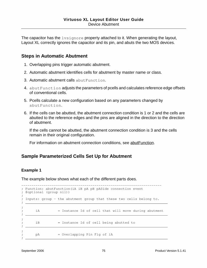
Virtuoso XL Layout Editor User GuideDevice Abutment
The capacitor has the lvsignore property attached to it. When generating the layout,Layout XL correctly ignores the capacitor and its pin, and abuts the two MOS devices.
Steps in Automatic Abutment
1. Overlapping pins trigger automatic abutment.
2. Automatic abutment identifies cells for abutment by master name or class.
3. Automatic abutment calls abutFunction.
4. abutFunction adjusts the parameters of pcells and calculates reference edge offsetsof conventional cells.
5. Pcells calculate a new configuration based on any parameters changed byabutFunction.
6. If the cells can be abutted, the abutment connection condition is 1 or 2 and the cells areabutted to the reference edges and the pins are aligned in the direction to the directionof abutment.
If the cells cannot be abutted, the abutment connection condition is 3 and the cellsremain in their original configuration.
For information on abutment connection conditions, see abutFunction.
Sample Parameterized Cells Set Up for Abutment
Example 1
The example below shows what each of the different parts does.
---------------------------------------------------------------------; Function: abutFunction(iA iB pA pB pASide connection event; @optional (group nil));; Inputs: group - the abutment group that these two cells belong to.; ______________________________________________________________________
;; iA = Instance Id of cell that will move during abutment; ______________________________________________________________________
;; iB = Instance Id of cell being abutted to; ______________________________________________________________________
;; pA = Overlapping Pin Fig of iA; ______________________________________________________________________
September 2006 75 Product Version 5.1.41

Virtuoso XL Layout Editor User GuideDevice Abutment
;; pB = Overlapping Pin Fig of iB; ______________________________________________________________________
;; pASide = Abutting pin access direction; ______________________________________________________________________
;connection = an integer value of 1 or 2 that indicates:
;; 1. pins are connected to the same net and do not; connect to any other pin.;; 2. pins are connected to the same net and the net; connects to other pins; ______________________________________________________________________
;; event = integer that represents abutment event:;; 1. compute abutment offset; 2. pcell parameter adjustment for abutment; 3. pcell parameter adjustment for unabutment; ______________________________________________________________________
;; group = abutment group pointer available to events 2 and 3; ______________________________________________________________________
;; Outputs: depends;; Side effects:;procedure( abutFunction(iA iB pA pB pASide connection event @optional (groupnil))
prog((result)
case(event(1 ; Compute offset
result = getAbutmentOffset(iA iB pA pB pASide connection))(2 ; Adjust pcell parameters
result = setAbutmentParams(iA iB pA pB pASide connection group))(3 ; Adjust pcell parameters back to default resetAbutmentParams(group iA iB)
result = t)(t ; Anything else return a nil
result = nil
))return(result))
)
Example 2
The example below shows how to add abutment properties to pins in an inverter pcell.
September 2006 76 Product Version 5.1.41

Virtuoso XL Layout Editor User GuideDevice Abutment
; *** the following 4 pins are on metal1 and are on ***; *** the power and ground rails. This will allow ***; *** abutment to other standard cells ***
obj = leftVddPin~>dbIddbReplaceProp(obj "abutAccessDir" "list" list("left"))dbReplaceProp(obj "abutClass" "string" "stdcell")dbReplaceProp(obj "abutFunction" "string" "stdCellFunc")
; *** the following property is a technique for passing ***; *** information to the user defined function. In this ***; *** case the minimum cell height is dependent on many ***; *** factors including design rules and is originally ***; *** calculated in the pcell code. This avoids ***; *** duplicating calculations in the user-defined ***; *** function ***
dbReplaceProp(obj "minCellHeight" "float" minH)
obj = rightVddPin~>dbIddbReplaceProp(obj "abutAccessDir" "list" list("right"))dbReplaceProp(obj "abutClass" "string" "stdcell")dbReplaceProp(obj "abutFunction" "string" "stdCellFunc")dbReplaceProp(obj "minCellHeight" "float" minH)
obj = leftGndPin~>dbIddbReplaceProp(obj "abutAccessDir" "list" list("left"))dbReplaceProp(obj "abutClass" "string" "stdcell")dbReplaceProp(obj "abutFunction" "string" "stdCellFunc")dbReplaceProp(obj "minCellHeight" "float" minH)
obj = rightGndPin~>dbIddbReplaceProp(obj "abutAccessDir" "list" list("right"))dbReplaceProp(obj "abutClass" "string" "stdcell")dbReplaceProp(obj "abutFunction" "string" "stdCellFunc")dbReplaceProp(obj "minCellHeight" "float" minH)
; *** The following 4 pins are the diffusion pins ***; *** of the individual MOS devices in the inverter ***; *** this will allow abutment of other individual ***; *** MOS devices to the inverter ***
obj = POutPin~>dbIddbReplaceProp(obj "abutAccessDir" "list" list("right"))dbReplaceProp(obj "abutClass" "string" "ptran")dbReplaceProp(obj "abutFunction" "string" "mosAbutFunc")dbReplaceProp(obj "contactParam" "string" "POutCnts")dbReplaceProp(obj "w" "float" pw); *** the automatic spacing properties are used if abutment fails ***dbReplaceProp(obj "vxlInstSpacingDir" "list" list("right"))dbReplaceProp(obj "vxlInstSpacingRule" "float" .35 )
obj = NOutPin~>dbIddbReplaceProp(obj "abutAccessDir" "list" list("right"))dbReplaceProp(obj "abutClass" "string" "ntran")dbReplaceProp(obj "abutFunction" "string" "mosAbutFunc")dbReplaceProp(obj "contactParam" "string" "NOutCnts")dbReplaceProp(obj "w" "float" nw)dbReplaceProp(obj "vxlInstSpacingDir" "list" list("right"))dbReplaceProp(obj "vxlInstSpacingRule" "float" .35 )
September 2006 77 Product Version 5.1.41

Virtuoso XL Layout Editor User GuideDevice Abutment
obj = PPwrPin~>dbIddbReplaceProp(obj "abutAccessDir" "list" list("left"))dbReplaceProp(obj "abutClass" "string" "ptran")dbReplaceProp(obj "abutFunction" "string" "mosAbutFunc")dbReplaceProp(obj "contactParam" "string" "PPwrCnts")dbReplaceProp(obj "w" "float" pw)dbReplaceProp(obj "vxlInstSpacingDir" "list" list("left"))dbReplaceProp(obj "vxlInstSpacingRule" "float" .35 )
obj = NPwrPin~>dbIddbReplaceProp(obj "abutAccessDir" "list" list("left"))dbReplaceProp(obj "abutClass" "string" "ntran")dbReplaceProp(obj "abutFunction" "string" "mosAbutFunc")dbReplaceProp(obj "contactParam" "string" "NPwrCnts")dbReplaceProp(obj "w" "float" nw)dbReplaceProp(obj "vxlInstSpacingDir" "list" list("left"))dbReplaceProp(obj "vxlInstSpacingRule" "float" .35 )
Creating CMOS Pcells to Use with Abutment
To create a pcells that has a built-in abutment capability,
1. Create a pcell specifically for abutment.
Editing an existing pcell for abutment is much more difficult than creating a new one forthe purpose. For information on creating pcells, see the Virtuoso Parameterized CellReference.
2. Specify the conditional inclusion or exclusion of contacts. For information, seeabutCondInclusion.
September 2006 78 Product Version 5.1.41

Virtuoso XL Layout Editor User GuideDevice Abutment
3. Identify gate pins. For information, see abutGateNet.
4. Specify the access direction. For information, see abutAccessDir.
5. Specify stretchable material. For information, see abutStretchMat.
❑ The first element in the abutStretchMat list is drainStretch.
gatenet.gif
accessdir.gif
September 2006 79 Product Version 5.1.41

Virtuoso XL Layout Editor User GuideDevice Abutment
❑ The second element in the abutStretchMat list is abutMinExt.
❑ The third element in the abutStretchMat list is abutRule1Ext.
❑ The fourth element in the abutStretchMat list is abutRule2Ext.
September 2006 80 Product Version 5.1.41
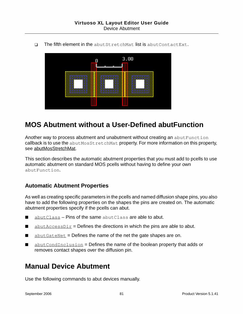
Virtuoso XL Layout Editor User GuideDevice Abutment
❑ The fifth element in the abutStretchMat list is abutContactExt.
MOS Abutment without a User-Defined abutFunction
Another way to process abutment and unabutment without creating an abutFunctioncallback is to use the abutMosStretchMat property. For more information on this property,see abutMosStretchMat.
This section describes the automatic abutment properties that you must add to pcells to useautomatic abutment on standard MOS pcells without having to define your ownabutFunction.
Automatic Abutment Properties
As well as creating specific parameters in the pcells and named diffusion shape pins, you alsohave to add the following properties on the shapes the pins are created on. The automaticabutment properties specify if the pcells can abut.
■ abutClass – Pins of the same abutClass are able to abut.
■ abutAccessDir = Defines the directions in which the pins are able to abut.
■ abutGateNet = Defines the name of the net the gate shapes are on.
■ abutCondInclusion = Defines the name of the boolean property that adds orremoves contact shapes over the diffusion pin.
Manual Device Abutment
Use the following commands to abut devices manually.
contactext.gif
September 2006 81 Product Version 5.1.41

Virtuoso XL Layout Editor User GuideDevice Abutment
■ Edit – Transistor Chaining lets you abut devices interactively while you are editing alayout. For more information, see “Chaining Transistors Interactively” on page 82.
■ Create – Pick from Schematic lets you abut devices while using the Pick FromSchematic command to generate a layout. For more information, see “ChainingTransistors during Pick From Schematic” on page 85.
■ Edit – Move lets you control abutment while moving devices. For more information, see“Moving Chained Transistors” on page 86.
Chaining Transistors Interactively
Transistor chaining is the process by which a list of MOS transistors or the fingers of foldedtransistors are abutted in a specific order. Chaining helps reduce layout area andcapacitance.
Prerequisites
The transistors to be chained
■ Must be set up for abutment. For more information, see “Setting Up Cells for Abutment”on page 73.
■ Must have the lxComponentType property set on the cell or library to which theybelong. You set this property using the Design – Component Types. For moreinformation, see “Component Types” on page 188.
All parameter values are retained after chaining. The chaining engine always creates pairs ofP and N chains with the P chain on top (because the power rail is typically at the top of a cell)and the N chain at the bottom (because the ground rail is typically at the bottom).
To chain transistors,
1. From the layout window menu bar, choose Edit – Transistor Chaining.
The Transistor Chaining form is displayed.
September 2006 82 Product Version 5.1.41

Virtuoso XL Layout Editor User GuideDevice Abutment
2. In the layout window, select the transistors to chain or click Add Cell ListBox to see thelist of transistors available for chaining.
The list box appears in the Transistor Chaining form.
Note: You can also select transistors in the layout window before you choose theTransistor Chaining command. The transistors you selected are highlighted in the listwhen you open the Transistor Chaining form.
3. Select the transistors to chain from the list box and click Apply.
The selected transistors are highlighted and you are prompted to select a destinationpoint in the layout window.
4. Move the cursor into the layout window.
The selected transistors appear as the image of a transistor chain that follows the cursor.
Folded transistors are chained with the number of fingers specified in the Set TransistorFolding form. For more information, see “Using Transistor Folding” on page 193.
Chains that comprise only NMOS or only PMOS transistors are aligned by the bottomedge. If you use the Gen From Source command to create a cluster comprising both
September 2006 83 Product Version 5.1.41
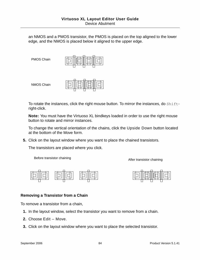
Virtuoso XL Layout Editor User GuideDevice Abutment
an NMOS and a PMOS transistor, the PMOS is placed on the top aligned to the loweredge, and the NMOS is placed below it aligned to the upper edge.
To rotate the instances, click the right mouse button. To mirror the instances, do Shift-right-click.
Note: You must have the Virtuoso XL bindkeys loaded in order to use the right mousebutton to rotate and mirror instances.
To change the vertical orientation of the chains, click the Upside Down button locatedat the bottom of the Move form.
5. Click on the layout window where you want to place the chained transistors.
The transistors are placed where you click.
Removing a Transistor from a Chain
To remove a transistor from a chain,
1. In the layout window, select the transistor you want to remove from a chain.
2. Choose Edit – Move.
3. Click on the layout window where you want to place the selected transistor.
PMOS Chain
NMOS Chain
Before transistor chaining After transistor chaining
September 2006 84 Product Version 5.1.41
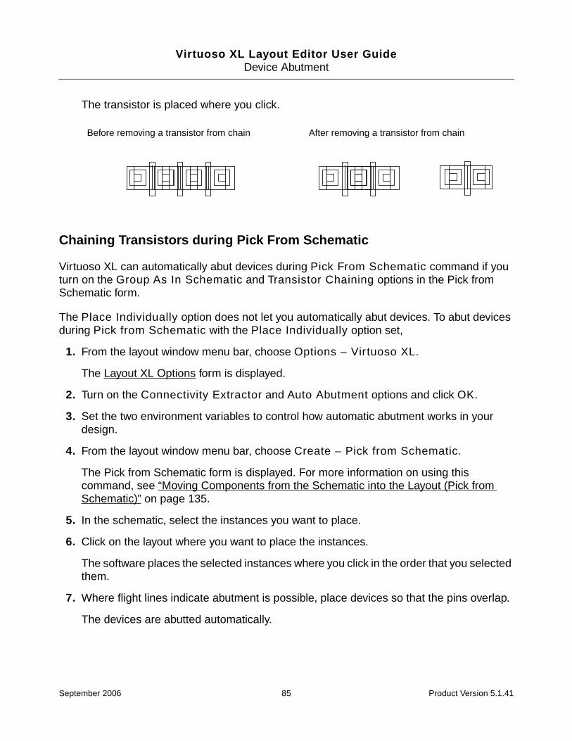
Virtuoso XL Layout Editor User GuideDevice Abutment
The transistor is placed where you click.
Chaining Transistors during Pick From Schematic
Virtuoso XL can automatically abut devices during Pick From Schematic command if youturn on the Group As In Schematic and Transistor Chaining options in the Pick fromSchematic form.
The Place Individually option does not let you automatically abut devices. To abut devicesduring Pick from Schematic with the Place Individually option set,
1. From the layout window menu bar, choose Options – Virtuoso XL.
The Layout XL Options form is displayed.
2. Turn on the Connectivity Extractor and Auto Abutment options and click OK.
3. Set the two environment variables to control how automatic abutment works in yourdesign.
4. From the layout window menu bar, choose Create – Pick from Schematic.
The Pick from Schematic form is displayed. For more information on using thiscommand, see “Moving Components from the Schematic into the Layout (Pick fromSchematic)” on page 135.
5. In the schematic, select the instances you want to place.
6. Click on the layout where you want to place the instances.
The software places the selected instances where you click in the order that you selectedthem.
7. Where flight lines indicate abutment is possible, place devices so that the pins overlap.
The devices are abutted automatically.
Before removing a transistor from chain After removing a transistor from chain
September 2006 85 Product Version 5.1.41

Virtuoso XL Layout Editor User GuideDevice Abutment
Moving Chained Transistors
Move chained devices by setting one of the following options in the Move form.
■ Chain Mode
For more information, see “Moving Chained Transistors in Chain Mode” on page 86.
■ Constraint Assisted Control
Virtuoso XL can set and maintain constraints added to instances. If some of theinstances being moved belong to a satisfied constraint, the abutment system mustmaintain the constraint. If abutment would cause a constraint to be broken, the abutmentsystem will not abut the two cells.
For more information, see “Moving Chained Transistors using ConstraintAssisted Control” on page 88 and “constraintAssistedMode” on page 484.
Moving Chained Transistors in Chain Mode
To move chained devices while maintaining the chains,
1. From the layout window menu bar, choose Edit – Move.
The Move form is displayed.
September 2006 86 Product Version 5.1.41
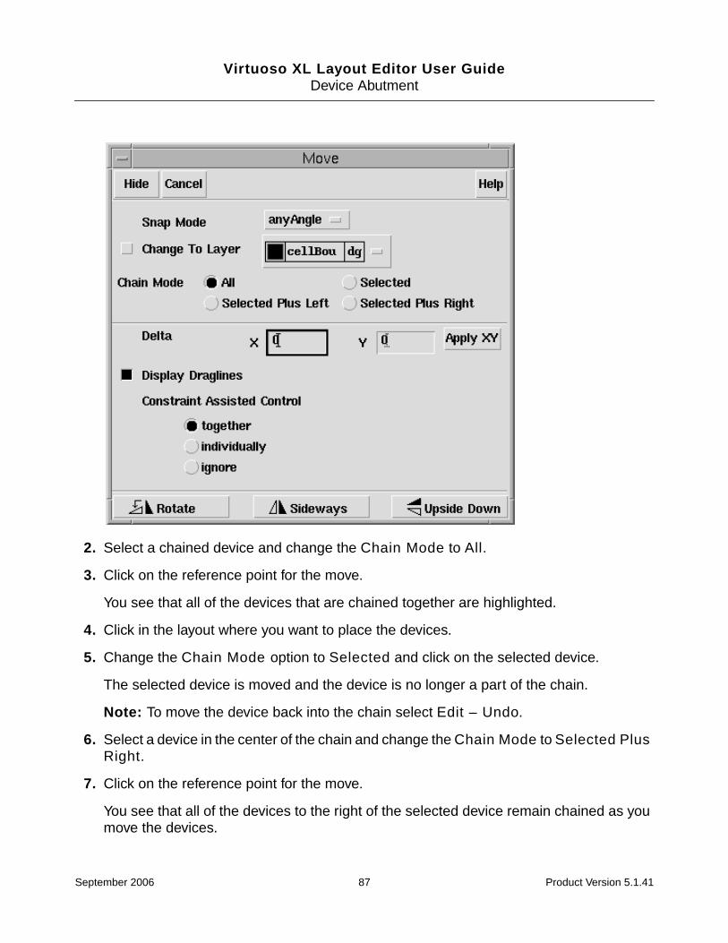
Virtuoso XL Layout Editor User GuideDevice Abutment
2. Select a chained device and change the Chain Mode to All.
3. Click on the reference point for the move.
You see that all of the devices that are chained together are highlighted.
4. Click in the layout where you want to place the devices.
5. Change the Chain Mode option to Selected and click on the selected device.
The selected device is moved and the device is no longer a part of the chain.
Note: To move the device back into the chain select Edit – Undo.
6. Select a device in the center of the chain and change the Chain Mode to Selected PlusRight.
7. Click on the reference point for the move.
You see that all of the devices to the right of the selected device remain chained as youmove the devices.
September 2006 87 Product Version 5.1.41
Virtuoso XL Layout Editor User GuideDevice Abutment
8. Click in the layout where you want to place the devices.
Note: The Selected Plus Left option selects all chained devices to the left of the selecteddevice.
Moving Chained Transistors using Constraint Assisted Control
To move chained transistors with constraint assisted control,
1. From the layout window, choose Edit – Move.
The Move form is displayed.
2. Under Constraint Assisted Control, turn on together or individually.
You can also activate constraint enforcement with the Constraint Assisted Modeoption in the Virtuoso XL Options form.
If you do not want constraints to have any influence on interactive moves, turn on ignore.
For more information on this form, see “Setting Environment Variables” on page 62.
3. Move an instance so that one of its pins touches the pin of another instance.
❑ If the two pins are on the same net, the instances are automatically abutted.
❑ If the two pins are on different nets but automatic pin permutation of one or both ofthe pins will bring two pins in the same net into contact, the pins are automaticallypermuted and the two instances abutted.
After abutment, the cell is modified in accordance with the pcell abutment parametersyou specified.
The system moves only one device to abut two cells. Of two instances that can beabutted, it chooses to move
a. A selected cell over a cell that is not selected.
b. A cell that is not already abutted over a cell that is already abutted
Automatic Device Abutment
Use the following commands to automatically abut devices.
■ Layout generation automatically abuts when the Transistor Chaining option is turnedon. For more information, see “Chaining Transistors Automatically during LayoutGeneration” on page 89.
September 2006 88 Product Version 5.1.41

Virtuoso XL Layout Editor User GuideDevice Abutment
■ The Update Components and Nets command automatically abuts devices when theTransistor Chaining option is turned on. For more information, see “ChainingTransistors Automatically during Update Components and Nets” on page 89.
Chaining Transistors Automatically during Layout Generation
To chain transistors automatically during layout generation,
1. From the layout window menu bar, choose Design – Gen From Source.
For more information, see “Generating a Layout with Components Not Placed (Gen FromSource)” on page 123.
2. In the Layout Generation section, turn on the Transistor Chaining option.
3. When you click OK, the software chains transistors automatically during layoutgeneration.
Tip
You can also set the environment variable initDoStacking to turn on transistorchaining from the Layout Generation Options form.
Chaining Transistors Automatically during Update Components and Nets
To chain transistors automatically when updating components and nets,
1. From the layout window menu bar, choose Connectivity – Update – Components andNets.
If the schematic has any devices that are missing from the layout, the Layout GenerationOptions form is displayed.
2. In the Layout Generation section, turn on the Transistor Chaining option.
3. When you click OK, the software chains transistors automatically during layoutgeneration.
September 2006 89 Product Version 5.1.41

Virtuoso XL Layout Editor User GuideDevice Abutment
Important
Update Components and Nets chains only new devices after running the LayoutGeneration Options with Transistor Chaining turned on. New chains areseparate and do not attach to old chains. Devices that had been chained prior torunning Update Components and Nets are not moved from their existingpositions.
For more information on this command, see “Updating Components and Nets (EngineeringChange Order Mode)” on page 426.
Abutting Parameterized Cells and Quick Cells
For information on how to code parameterized cells to automatically abut to Quick Cells, seeAppendix A, “Pcell and QCell Abutment,” in the Virtuoso Layout Editor Turbo User Guide.
September 2006 90 Product Version 5.1.41
Virtuoso XL Layout Editor User Guide
6Generating Your Layout
This chapter shows you how to use the Virtuoso® XL Layout Editor (Virtuoso XL) to generatea layout and make an initial placement of components in it.
This chapter covers the following topics:
■ Naming Conventions on page 91
■ Starting Virtuoso XL from the Schematic on page 94
■ Importing a Netlist for a Connectivity Reference on page 96
■ Starting Virtuoso XL from the Layout View on page 98
■ Defining the Design Boundary on page 105
■ Creating Template Files on page 112
■ Generating a Layout with Components Not Placed (Gen From Source) on page 123
■ Placing Components in a Layout in the Same Relative Position as in the Schematic(Place As In Schematic) on page 134
■ Moving Components from the Schematic into the Layout (Pick from Schematic) onpage 135
■ Cloning on page 144
For information on Virtuoso XL forms, see “Online Forms” on page 158.
Naming Conventions
When generating and manipulating components in the layout view, Layout XL uses thenaming conventions outlined in this section.
September 2006 91 Product Version 5.1.41

Virtuoso XL Layout Editor User GuideGenerating Your Layout
Important
Layout XL relies on these conventions when establishing correspondence betweenthe schematic and layout views. If you manually change a system-generated name,or if you rename an instance such that its new name conflicts with a system-generated name, the correspondence between schematic and layout might be lost.
General Convention
The OR bar ( | ) is used to delimit hierarchy and to prefix the names of all layout instancesgenerated by Layout XL.
Mfactored Devices and Folded Devices
Devices specified using the mfactor property in the schematic and those that are folded inthe layout are named instName.integer in the layout.
For example, if you have a schematic instance named P0 with
mfactor = 3
the layout instances generated are named as follows.
Series-Connected Devices
Devices specified using the sfactor property in the schematic are namedinstName.sinteger in the layout.
For example, if you have a schematic instance named R0 with
sfactor = 3
Schematic Layout
P0 |P0
NAN0/P0 |NAND0|P0
Schematic Layout
P0 |P0.1|P0.2|P0.3
September 2006 92 Product Version 5.1.41

Virtuoso XL Layout Editor User GuideGenerating Your Layout
the layout instances generated are named as follows.
lxCombination Devices
Devices defined using the lxCombination property in the schematic are namedinstName.msinteger in the layout.
For example, if you have a schematic instance named R0 with
lxCombination = 2*10K + 1*100K
the layout instances generated are named as follows.
Schematic Layout
R0 |R0.s1|R0.s2|R0.s3
Schematic Layout
R0 |R0.ms1|R0.ms2|R0.ms3
September 2006 93 Product Version 5.1.41

Virtuoso XL Layout Editor User GuideGenerating Your Layout
Starting Virtuoso XL from the Schematic
To start Virtuoso XL from a schematic window, follow these steps.
1. From the Command Interpreter Window (CIW), choose File – Open.
The Open File form is displayed. For more information on this form, see “Open File Form”in the Cadence Design Framework II User Guide.
2. In the Library Name cyclic field, choose a library name.
3. In the Cell Name field, type a cell name.
4. In the View Name cyclic field, choose a schematic view.
5. Click OK.
The schematic view you specified appears.
6. From the schematic window, choose Tools – Design Synthesis – Layout XL.
Note: Layout XL does not appear in the Tools menu unless the Virtuoso XL softwareis installed. If you do not see Layout XL in the Tools – Design Synthesis menu, checkwith your system administrator.
user/mnt2/home/cds.lib
September 2006 94 Product Version 5.1.41
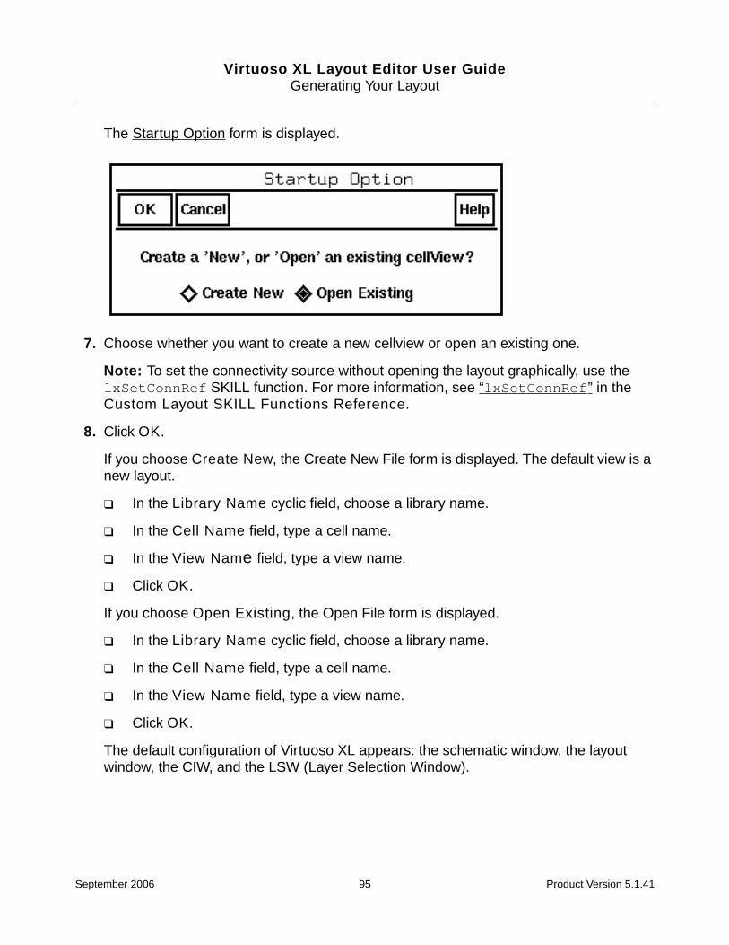
Virtuoso XL Layout Editor User GuideGenerating Your Layout
The Startup Option form is displayed.
7. Choose whether you want to create a new cellview or open an existing one.
Note: To set the connectivity source without opening the layout graphically, use thelxSetConnRef SKILL function. For more information, see “lxSetConnRef” in theCustom Layout SKILL Functions Reference.
8. Click OK.
If you choose Create New, the Create New File form is displayed. The default view is anew layout.
❑ In the Library Name cyclic field, choose a library name.
❑ In the Cell Name field, type a cell name.
❑ In the View Name field, type a view name.
❑ Click OK.
If you choose Open Existing, the Open File form is displayed.
❑ In the Library Name cyclic field, choose a library name.
❑ In the Cell Name field, type a cell name.
❑ In the View Name field, type a view name.
❑ Click OK.
The default configuration of Virtuoso XL appears: the schematic window, the layoutwindow, the CIW, and the LSW (Layer Selection Window).
September 2006 95 Product Version 5.1.41

Virtuoso XL Layout Editor User GuideGenerating Your Layout
Importing a Netlist for a Connectivity Reference
Important
Support for the netlist-driven flow described in this section has been discontinued inthis release. If you encounter a problem using the File – Import – XL Netlistcommand, use File – Import – CDL instead. Import CDL generates a schematicfrom your netlist. You can then use that schematic as the connectivity source for yourdesign. For more information on importing CDL, see “Translating CDL Files,” in theDesign Data Translator’s Reference.
To import a netlist to use as the connectivity source for a Virtuoso XL design, follow thesesteps.
Important
The netlist syntax must comply with the guidelines defined in “Using Spice and CDLfor Netlist-Driven Layout Generation” on page 678. If you do not follow theseguidelines, then the layout might not reflect the full intent of the netlist.
The netlist may contain user defined properties and generic parameters that can be passedto the layout instance generated from Virtuoso XL. Any parameter of type String, Boolean,int, and float is supported.
1. From the CIW, choose File – Import – XL Netlist.
September 2006 96 Product Version 5.1.41

Virtuoso XL Layout Editor User GuideGenerating Your Layout
The Import XL Netlist form is displayed.
2. In the Netlist File field, type the name of the input file (the netlist you want to import).
To see the names of your directories and files in the file browser, put the cursor in theNetlist File field and click Browse.
Note: Netlists in circuit description language (CDL) and SPICE (3f4) formats can beimported.
For information on importing CDL files, see “Translating CDL Files” in the Design DataTranslator’s Reference.
3. Choose whether you want to copy the imported netlist file to the destination library, linkthe imported netlist file to the destination library, or move the imported netlist file to thedestination library.
4. In the Library field, type the name of the library in which you want to store the netlist.
September 2006 97 Product Version 5.1.41

Virtuoso XL Layout Editor User GuideGenerating Your Layout
5. In the Cell field, type the name of the cell in which you want to store the netlist.
6. In the View field, type the name of the view you want to give the netlist.
To see the libraries, cells, and views in the Library Browser, put the cursor in the Libraryor Cell or View fields and click Browse.
7. Click OK.
Virtuoso XL imports the netlist to the library, cell, and view name you specified. You cannow use this netlist as a connectivity reference for a Virtuoso XL design.
Starting Virtuoso XL from the Layout View
To start the Virtuoso XL from a layout window, follow these steps.
1. From the CIW, choose File – Open.
The Open File form is displayed. For more information on this form, see “Open File Form”in the Cadence Design Framework II User Guide.
user/mnt2/home/cds.lib
September 2006 98 Product Version 5.1.41

Virtuoso XL Layout Editor User GuideGenerating Your Layout
2. In the Library Name cyclic field, choose a library name.
3. In the Cell Name field, type a cell name.
4. In the View Name cyclic field, choose a layout view.
5. Click OK.
The layout view you specified appears.
6. From the layout window, choose Tools – Layout XL.
The default configuration of Virtuoso XL appears: the schematic window, the layoutwindow, the CIW, and the LSW.
Note: Layout XL does not appear in the Tools menu unless the Virtuoso XL softwareis installed. If you do not see Layout XL in the Tools menu, check with your systemadministrator.
If the layout from which you chose the Layout XL command has no connectivityreference (schematic or netlist) associated with it, the Define Connectivity Referenceform is displayed.
7. Choose one of the following as the connectivity source type.
❑ If there is no connectivity reference for the layout, choose None.
Virtuoso XL is installed, but Virtuoso XL commands requiring information from aconnectivity source are disabled. You can define a connectivity reference at any timeby choosing Connectivity – Update – Source.
September 2006 99 Product Version 5.1.41

Virtuoso XL Layout Editor User GuideGenerating Your Layout
When you choose None (no connectivity reference), the connectivity modelrequires that the nets of pins and instance terminals cannot be changed, but the netsof all other shapes can be changed if they connect to a pin or instance terminal.
❑ If the connectivity reference is a schematic, choose Schematic and do one of thefollowing:
❍ Type the name of the library, cell, and view into Library, Cell, and View fields.
❍ Click Browse to see what cells are available in the Library Browser, and clickon a cell name in the Library Browser.
❍ Click Sel by Cursor and then click on an open schematic.
Click Update layout cellviews hierarchically to update the library setting for anyfor any lower-level cellviews in a hierarchical cellview.
You can click Browse to open the Library Browser to find a netlist and click on the netlistname to enter it in the Define Connectivity Reference form.
8. Click OK.
Virtuoso XL opens a schematic window showing the schematic you specified.
Connectivity Reference as a Netlist
Important
The netlist syntax must comply with the guidelines defined in “Using Spice and CDLfor Netlist-Driven Layout Generation” on page 678. If you do not follow theseguidelines, then the layout might not reflect the full intent of the netlist.
The netlist can contain user defined properties and generic parameters that can be passedto the layout instance generated from Virtuoso XL. Any parameter of type String, Boolean,int, and float is supported.
To specify a netlist as a connectivity reference,
1. Choose Netlist in the Define Connectivity Reference form.
September 2006 100 Product Version 5.1.41

Virtuoso XL Layout Editor User GuideGenerating Your Layout
The form changes to let you enter the name of the Map File and the Top Cell of thenetlist.
2. Type the name of a Virtuoso XL map file to import or click Browse to open the LibraryBrowser to find a netlist and click on the netlist name to enter it in the Define ConnectivityReference form.
The Virtuoso XL map file lists model, cell (subcircuit), and instance properties and mapsthem to the names they have in the layout.
You can also use the Virtuoso XL map file to map terminal names in the netlist (such asresistor terminal names Plus and Minus) to terminal names in the layout (such asresistor terminal names A and B), and parameter names in the netlist (such as theresistance value r) to parameter names in the layout (such as the resistance value R).
The Connectivity – Update – Source command loads the information in the VirtuosoXL map file into the cellview you specify on the form, overwriting any previously enteredinformation. The Virtuoso XL map file structure, with an example, is shown in “VirtuosoXL Map File Structure” on page 102.
September 2006 101 Product Version 5.1.41

Virtuoso XL Layout Editor User GuideGenerating Your Layout
Virtuoso XL Map File Structure
The Virtuoso XL map file consists of a model, subcircuit, or cell mapping section,lxNetlistCellMap, which is mandatory when using a netlist source, and an instancemapping section, lxNetlistInstMap;
lxNetlistCellMap((device_class
(device_type(property)(property)...
)(property)(property)...
))
lxNetlistInstMap((hier_inst(property)(property)...)(hier_inst
(property)(property)...
))
■ device_class is the model card name (for example, M, R or C) specified in quotes. Itapplies only to the netlist-driven flow, however, it still needs to be specified as a blankstring in schematic map file.
■ device_type identifies the model, subcircuit, or cell in the source. It contains akeyword, a separator, and a name. The keyword can be model or subckt or cell; theseparator is the equals character ( = ); and the name is a quoted string specifying themodel, subcircuit, or library and cell name.
■ hier_inst is a hierarchical instance in the source specified as a quoted string withforward slashes as the hierarchical delimiter. For example, “/X1/X22/M3” wouldrepresent an instance M3 in subcircuit X22 which is in turn instantiated in subcircuit X1.
■ property can be one or more of the supported properties listed below. You can definethese properties for either device_class or device_type underlxNetlistCellMap, and for hier_inst under lxNetlistInstMap.
❑ useCell “libName cellName” specifies the layout cell to be used toimplement the device.
September 2006 102 Product Version 5.1.41

Virtuoso XL Layout Editor User GuideGenerating Your Layout
❑ paramNameMap list defines the mapping between device parameters in thesource schematic and the parameters of the layout cell, in the form(“device_param” “cell_param”).
❑ pinNameMap “list” defines the mapping between the device terminals in thesource schematic and the terminals of the layout cell, in the form (“device_pin”“cell_pin”)
❑ paramSet “list” sets the parameters listed to the given values and types, in theform (“name” “type” “value”).
❑ stopList “list” lists the view names that stop hierarchy traversal for the cell orthe instance.
❑ ignorePins “list” specifies names of pins to be ignored during layoutgeneration and check against source.
❑ ignoreParams “list” specifies the names of parameters to be ignored duringlayout generation and check against source.
❑ ignoreNames “list” defines the names of instances to be ignored during layoutgeneration and check against source. For information on how to set this property,see Examples.
❑ ignoreCells “list” defines the names of cells to be ignored during layoutgeneration and check against source. For information on how to set this property,see Examples.
Note: Properties defined at a higher level apply to all devices defined at that level orlower, except where they are locally overwritten. The order in which devices andproperties are defined in the Virtuoso XL map file is irrelevant.
Examples
The following example illustrates a map file suitable for use in a netlist-driven flow.
lxNetlistCellMap(
("M"(("MODEL" "=" "P")
(useCell "refLib pmos")(paramNameMap ("WP" "w")("wp" "w")("LP" "l")("lp" "l"))
))
(("MODEL" "=" "N")(useCell "refLib nmos")(paramNameMap ("WN" "w")("wn" ""w")("LN" "l")("ln" "l"))
)(paramNameMap ("W" "w") ("L" "l") ("M" "m") ("C" "c"))(pinNameMap ("s" "S") ("g" "G") ("d" "D")("b" "B"))
September 2006 103 Product Version 5.1.41

Virtuoso XL Layout Editor User GuideGenerating Your Layout
(paramSet("l" "float" 1.0)("w" "float" 1.3)("showLabels?" "boolean" t)
)(stopList "layout compacted symbolic")
))
To ignore a specific cell during layout generation or check against source, use the following.
lxNetlistCellMap(
("myLib myCell"(ignoreCells "myLib myCell")
))
To ignore an instance of a particular cell during layout generation or check against source,use one of the following.
lxNetlistCellMap(
("myLib myCell"(ignoreNames "myInstance")
))
Or
lxNetlistInstMap(
("myInstance"(ignoreCells "myLib myCell")
))
To ignore an instance during layout generation or check against source, use the following.
lxNetlistInstMap(
("myInstance"(ignoreNames "myInstance")
))
Using a Map File in a Schematic Driven Flow
In a schematic-driven flow, the VIrtuoso XL map file lets you use a different set of layout cellsto map to the schematic masters (similar to the lxUseCell property). This might be necessary
September 2006 104 Product Version 5.1.41

Virtuoso XL Layout Editor User GuideGenerating Your Layout
if you do not have permission to write to the schematic and therefore cannot add thenecessary lxUseCell properties.
For Virtuoso XL to search for any instance in a schematic flow, the device_class must beempty which means that you cannot specify M, R, C, and so on. Additionally, you should usethe library and cell name instead of the model name. Below is an example of a map file to usein a schematic driven flow.
Note: Properties defined at a higher level apply to all devices defined at that level or lower,except where they are locally overwritten. The order in which devices and properties aredefined in the Virtuoso XL map file is irrelevant.
Example
The following example illustrates a map file suitable for use in a schematic-driven flow. Forinformation on how to use the different ignore properties, see Examples.
lxNetlistCellMap(
(""(("model" "=" "gpdk nmos")
(useCell "myGPDK nmos")(stopList "myLayout")
)(("model" "=" "gpdk pmos")
(useCell "myGPDK pmos")(stopList "myLayout")
)(paramNameMap ("w1" "w") ("l1" "l")))(""
(("model" "=" "gpdk nmos_hv")(useCell "myGPDK nmos_hv")(stopList "myLayout")
)(("model" "=" "gpdk pmos_hv")
(useCell "myGPDK pmos_hv")(stopList "myLayout")
)(paramNameMap ("w2" "w") ("l2" "l")))
)
Defining the Design Boundary
When you initialize a layout, Virtuoso XL provides a design boundary.
To reset the default size for the design boundary, choose the layout window Design – GenFrom Source command and set the options in the Boundary section. For information on
September 2006 105 Product Version 5.1.41

Virtuoso XL Layout Editor User GuideGenerating Your Layout
how to do this, see “Generating a Layout with Components Not Placed (Gen From Source)”on page 123.
To stretch, move, or delete the design boundary, use the layout editor Edit commands. Formore information on these commands, see “Editing Objects” in the Virtuoso Layout EditorUser Guide.
The design boundary must be a valid layer in the LSW and must be layer prBoundary orlayer cellBoundary, or else it must have the purpose boundary (by).
To place all objects and pins inside the boundary, use the layout window’s Edit – Place fromSchematic command. For more information, see “Placing Components in a Layout in theSame Relative Position as in the Schematic (Place As In Schematic)” on page 134.
To draw a new design boundary, follow these steps.
1. If you are using the Layout Generation Options form to generate a new layout, turn offBoundary.
2. In the LSW, click on the prBoundary layer.
The boundary layer appears as the current layer at the top of the LSW. You can alsouse the layer cellBoundary from the Layout Generation Options form Boundarysection Layer cyclic field.
3. From the layout window, choose Create – Rectangle or Create – Polygon.
For information on these commands, see “Using the Placer” on page 213.
4. Draw the design boundary in the layout window where you want it placed.
❑ For a rectangular boundary, click to place one corner of the new boundary, drag themouse to place the opposite corner, and release the mouse button.
❑ For a polygonal boundary, use the cursor to click on the first point, each corner point,and end point (identical to the first point) of the polygon.
The new boundary appears in the layout window.
Note: if there are multiple shapes on the prBoundary or cellBoundary layers, amessage box appears (only once) asking you to select which one is the top-level boundary.
Automatic Area Estimation
When you specify a rectangular boundary in the Layout Generation Options form, you canspecify that Virtuoso XL estimates the area required to accommodate the design.
September 2006 106 Product Version 5.1.41
Virtuoso XL Layout Editor User GuideGenerating Your Layout
You specify the percentage of the area within the cell boundary that you want the componentsto fill, the aspect ratio of the design boundary, and an Area Calculation function, whichcontrols the shapes that are used to calculate the contents of the design and, in turn, the arearequired to accommodate them.
There are two predefined area calculation functions, which are described below.
■ PRBoundary Based uses the place and route boundaries of the individual lower-levelcells to calculate the area. This provides more accurate results and more compactlayouts, especially when working with rectilinear blocks.
■ BBox Based uses the bounding boxes of cellview masters to calculate the area. Thederived bounding box is typically larger than the place and route boundary in standardcells because of metal overhangs and presence of text display objects and labels. Thiscan result in pessimistic area estimates with values much higher than would be expectedfor a compact layout.
For more information on these functions, see “Layout Generation Options” on page 163.
Alternatively, you can define your won area estimation function. For more information on howto do this, see User-Defined Area Estimation Functions.
User-Defined Area Estimation Functions
Syntax
function_name(dbCellViewID)
=> x_area
Description
Returns an estimate of the area required to accommodate the design represented by thespecified cellview ID. If the value returned is negative, its absolute value is taken.
The value returned is divided by the Utilization factor and the boundary shape determinedusing the Aspect Ratio specified in the Layout Generation Options form.
September 2006 107 Product Version 5.1.41

Virtuoso XL Layout Editor User GuideGenerating Your Layout
Important
When the Transistor Chaining and Transistor Folding options are switched on,the Utilization is applied only after chaining and folding is complete in order tocalculate the size of the PR boundary accurately.
Arguments
Value Returned
Example
You can define your own area estimation function as follows.
procedure(myFunc(cvId)let( (area inst)area = 0.0foreach( inst cvId~>instancesx1 = caar(inst~>bBox)x2 = caadr(inst~>bBox)y1 = cadar(inst~>bBox)y2 = cadadr(inst~>bBox)printf("%L\n" inst~>bBox)printf("%f %f %f %f\n" x1 y1 x2 y2)area = area + abs(x1-x2)*abs(y1-y2)
)area
))
This function
■ Traverses all the instances defined in the cellview cvId
■ Calculates the sum of the areas of the bounding boxes of each instance
■ Returns the area value
You specify this area estimation function in the Boundary Area Estimation group box in theLayout Generation Options form.
cellviewID The database ID of the cellview whose area you want toestimate.
x_area The estimated area required to accommodate the specifiedcellview expressed as either a float or an integer.
September 2006 108 Product Version 5.1.41

Virtuoso XL Layout Editor User GuideGenerating Your Layout
1. From the Area Calculation cyclic field, choose User Defined.
2. Type the name of the function into the text field.
For example, to use the function above, you would type myFunc into the text field.
Note: Type in only the name of the function. The cellview ID is the currently opencellview.
Working with Template Files
Options from the Pin Placement, Partitioning, Placement Planning, Layout Generation,and Update Components and Nets commands are saved to the cellview. These optionscan be copied from the cellivew into template files. The template files can then be used toupdate or redo sections of your design.
Use the Design – Save To Template command to create template files. You can chose tosave;
■ Boundary information
■ I/O pin layers, multiplicity, sizes, and types.
■ Pin locations
■ Pin constraints
■ Partitioning information
■ Row information
Templates can contain all of the available sections or just a subset of the available sections.For example, you might use separate templates for your I/O pin constraints and rowinformation.
Table 6-1 Template Sections and Contents
Template Section Scope of the Template
Boundary The boundary shape and layer
There are a variety of ways to define the shape of a boundary inthe Layout Generation Options form.
I/O Pins Location The location info from the Pin Placement form.
I/O Pins Constraints The edge, etc. info from the Pin Placement form.
September 2006 109 Product Version 5.1.41

Virtuoso XL Layout Editor User GuideGenerating Your Layout
Saving Form Contents
Use the Design – Save to Template command to save the form information to an ASCIIfile. The template file is used to modify or delete the design data or create new data in thedesign. To be able to reuse this information, you must create template files. Specify theinformation that you want to save in the Template File form and that information is written fromthe cellview to the template file.
Note: If you exit Design Framework II and do not save the design, then the form settings arenot saved to the cellview. Use the Design – Save command to save the form settings.
All the information on the forms is updated to the cellview when you click the OK or Applybuttons. You can then save the information to a template file using the Design – Save ToTemplate command.
The template file name is stored in the cellview. The template file name is then used by defaultwhen opening the form.
Loading Template Files
You can load template files while working with several different command forms. The type oftemplate information you can save or load depends on what is appropriate to the current task.
Rows The row information from the Placement Planning form.
Partitions The partition information from the Partitioning form.
Table 6-2 Commands and Template Sections
This Command... Lets You Save and Load ThisTemplate Information...
Design – Gen From Source Pin and Boundary
Connectivity – Update – Components and Nets Pin and Boundary
Place – Pin Placement Constraints
Place – Pin Placement Pin Location and Constraints
Place – Partitioning Partitions
Table 6-1 Template Sections and Contents, continued
Template Section Scope of the Template
September 2006 110 Product Version 5.1.41

Virtuoso XL Layout Editor User GuideGenerating Your Layout
Modifying Template Files
To modify templates, edit the file with a text editor. Follow the syntax rules described in“Template File Syntax” on page 113.
Modifying a template file using VI has no effect on any cellview until you load it into thatcellview.
If you modify the form then that information is read into the cellview.
Loading Template Files
To load existing information about pins, the design boundary, partitions, or rows from atemplate file into the corresponding form, follow these steps.
1. From the layout window, select either Place – Pin Placement, Place – Partitioning,Place – Placement Planning, Design – Gen From Source, or Connectivity –Update – Components and Nets.
2. Type in the template name in the Template field.
Note: In the Pin Placement form click the Template file button to choose the templatefile from the Load Template File form.
3. If you would like a different template select Browse.
Place – Placement Planning Row
Table 6-2 Commands and Template Sections, continued
This Command... Lets You Save and Load ThisTemplate Information...
September 2006 111 Product Version 5.1.41
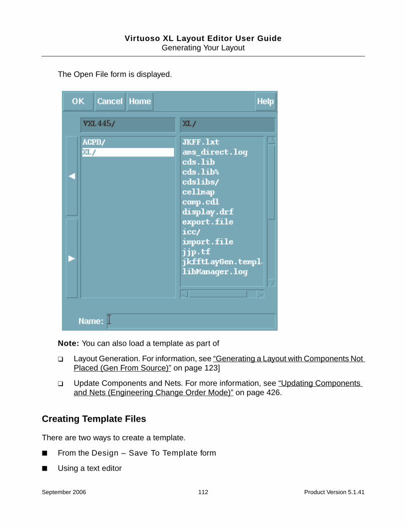
Virtuoso XL Layout Editor User GuideGenerating Your Layout
The Open File form is displayed.
Note: You can also load a template as part of
❑ Layout Generation. For information, see “Generating a Layout with Components NotPlaced (Gen From Source)” on page 123]
❑ Update Components and Nets. For more information, see “Updating Componentsand Nets (Engineering Change Order Mode)” on page 426.
Creating Template Files
There are two ways to create a template.
■ From the Design – Save To Template form
■ Using a text editor
September 2006 112 Product Version 5.1.41

Virtuoso XL Layout Editor User GuideGenerating Your Layout
To save current information about pins and design boundary from the cellview to a templatefile, follow these steps.
1. From the layout window, choose Design – Save To Template.
The Template File form is displayed.
2. In the Template file name field type a template file name, ex.row.lxt
3. Select the sections of the template file you want to save (I/O Pin Locations, I/O PinConstraints, Boundary, Rows, and Partitions). If you want to save all selections,select All.
4. Click OK. The data you selected is saved in the template file.
Template File Syntax
Template files generally follow the syntax rules for technology files, but they are nottechnology file fragments.
Templates contain these sections:
■ Boundaries Section
■ I/O Pins Section
September 2006 113 Product Version 5.1.41
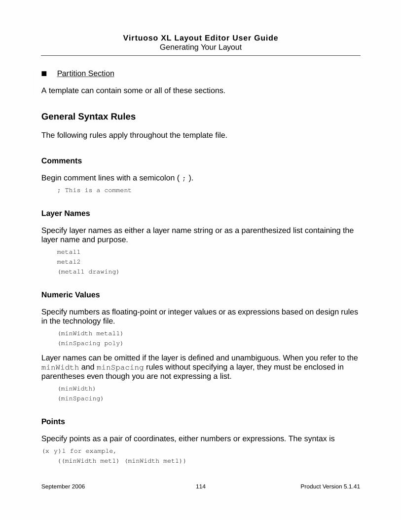
Virtuoso XL Layout Editor User GuideGenerating Your Layout
■ Partition Section
A template can contain some or all of these sections.
General Syntax Rules
The following rules apply throughout the template file.
Comments
Begin comment lines with a semicolon ( ; ).
; This is a comment
Layer Names
Specify layer names as either a layer name string or as a parenthesized list containing thelayer name and purpose.
metal1
metal2
(metal1 drawing)
Numeric Values
Specify numbers as floating-point or integer values or as expressions based on design rulesin the technology file.
(minWidth metal1)
(minSpacing poly)
Layer names can be omitted if the layer is defined and unambiguous. When you refer to theminWidth and minSpacing rules without specifying a layer, they must be enclosed inparentheses even though you are not expressing a list.
(minWidth)
(minSpacing)
Points
Specify points as a pair of coordinates, either numbers or expressions. The syntax is
(x y)l for example,
((minWidth met1) (minWidth met1))
September 2006 114 Product Version 5.1.41

Virtuoso XL Layout Editor User GuideGenerating Your Layout
((minSpacing met2) 3)
Offset Points
Specify offset coordinates in a sequence of points as a relative shift from another point. Thekeyword D identifies offset coordinates. The syntax is
(D x y)
For example:
(D 3 5)
(D (minWidth met1) 7)
Sequences of Points
Specify a sequence of points as a list of points or offsets.
(0 0) (D 10 0) (D 0 20) (D -10 0)
(D 10 0) (D 0 10) (D -10 0)
If the first item is an offset, the entire list must be composed of offsets.
Polygons
Specify polygons using the polygon keyword followed by a sequence of points. The syntax is
(polygon sequence_of_points)
The last point of the sequence is always connected by an edge to the first one, even if suchan edge does not appear in the sequence. Clockwise and counterclockwise orders are bothacceptable. Polygons characterized by a sequence of offsets (no fixed points) are calledfloating polygons. If a floating polygon is encountered in a context where a non-floatingpolygon is expected, the first point is implicitly set to (0 0).
The following examples all describe the same polygon
(polygon (0 0) (D 10 0) (D 0 20) (D -10 0))
(polygon (0 0) (D 10 0) (10 20) (D -10 0))
(polygon (0 20) (0 0) (10 0) (10 20))
Rectangles
Specify rectangles using the rectangle keyword and the options in the table below. Thesyntax is
September 2006 115 Product Version 5.1.41
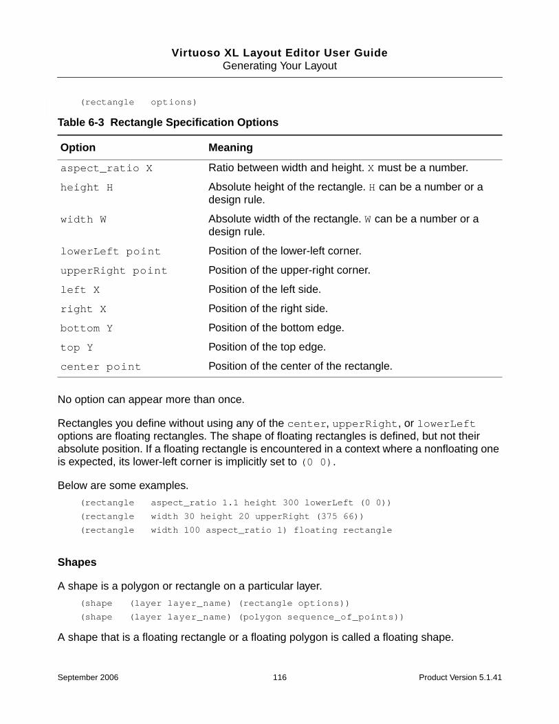
Virtuoso XL Layout Editor User GuideGenerating Your Layout
(rectangle options)
No option can appear more than once.
Rectangles you define without using any of the center, upperRight, or lowerLeftoptions are floating rectangles. The shape of floating rectangles is defined, but not theirabsolute position. If a floating rectangle is encountered in a context where a nonfloating oneis expected, its lower-left corner is implicitly set to (0 0).
Below are some examples.
(rectangle aspect_ratio 1.1 height 300 lowerLeft (0 0))
(rectangle width 30 height 20 upperRight (375 66))
(rectangle width 100 aspect_ratio 1) floating rectangle
Shapes
A shape is a polygon or rectangle on a particular layer.
(shape (layer layer_name) (rectangle options))
(shape (layer layer_name) (polygon sequence_of_points))
A shape that is a floating rectangle or a floating polygon is called a floating shape.
Table 6-3 Rectangle Specification Options
Option Meaning
aspect_ratio X Ratio between width and height. X must be a number.
height H Absolute height of the rectangle. H can be a number or adesign rule.
width W Absolute width of the rectangle. W can be a number or adesign rule.
lowerLeft point Position of the lower-left corner.
upperRight point Position of the upper-right corner.
left X Position of the left side.
right X Position of the right side.
bottom Y Position of the bottom edge.
top Y Position of the top edge.
center point Position of the center of the rectangle.
September 2006 116 Product Version 5.1.41

Virtuoso XL Layout Editor User GuideGenerating Your Layout
Layers can also be defined externally, within the scope of the option using a shape for its owndefinition. A layer defined as part of the shape definition overwrites all external layerdefinitions.
Header Section
The header section is used by the parser. Do not edit or remove the template headercomments.
(lxTemplatefileHeader; (version 1.1); (creator "Template File Writer"); (design "VCPLIB" "DFF" "layout" ); (timeGenerated "May 20 11:13:41 2003")
Boundaries Section
The boundaries section defines the shape of the boundary. The syntax is
boundary_section([(boundary options)]
)
Boundaries Options
The options are
shape The shape outlining the boundary. By default, the shape is arectangle with the aspect ratio defined by initAspectRatioin the .cdsenv file. By default, or if the shape is floating, thelower left corner is placed at (0 0).
layer layer_name
The boundary layer name. The default is prBoundary.
utilization N
September 2006 117 Product Version 5.1.41

Virtuoso XL Layout Editor User GuideGenerating Your Layout
Below is an example boundary definition:
boundary_section((boundary
(shape (layer prBoundary) (rectangle aspect_ratio 1.1))(utilization 0.25)
))
Below is a second boundary example:
boundary_section((boundary
(layer ("prBoundary" "boundary"))(utilization 0.250000)(shape (rectangle aspect_ratio 1.000000 lowerLeft (0.0 0.0)))
))
I/O Pins Section
The I/O pins section defines the shape and layer of the I/O pins for the new layout. The syntaxis
IO_section([global_pin_options]...[(pin {pin_name | ( pin_name1 pin_name2 ... )} pin_options)]...[changes to global pin options][more pins]...
)
Every pin entry has one or more pin names, corresponding to net names for which pins aredefined. Pins have one or more options. Global options appear outside of a pin entry andare overridden by corresponding pin-specific options. Changes to global options apply tosubsequent pins (unless the pins each set a value for the corresponding option).
The global options in effect at the end of the I/O pins section apply to all pins not defined inthe template.
The area utilization factor.
This factor is used to compute the boundary size for rectangularboundaries that do not fully define the size in the shape options.It is applied only after any chaining and folding is complete.
The value is ignored for polygonal boundaries and forrectangular boundaries whose shape options fully specify thedimensions. The default is the value of initUtilization inthe .cdsenv file.
September 2006 118 Product Version 5.1.41
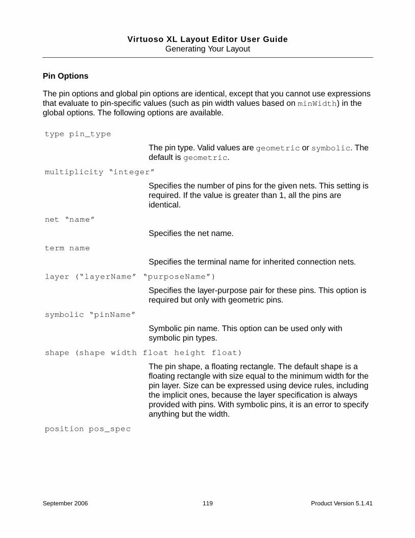
Virtuoso XL Layout Editor User GuideGenerating Your Layout
Pin Options
The pin options and global pin options are identical, except that you cannot use expressionsthat evaluate to pin-specific values (such as pin width values based on minWidth) in theglobal options. The following options are available.
type pin_type
The pin type. Valid values are geometric or symbolic. Thedefault is geometric.
multiplicity “integer”
Specifies the number of pins for the given nets. This setting isrequired. If the value is greater than 1, all the pins areidentical.
net “name”
Specifies the net name.
term name
Specifies the terminal name for inherited connection nets.
layer (“layerName” “purposeName”)
Specifies the layer-purpose pair for these pins. This option isrequired but only with geometric pins.
symbolic “pinName”
Symbolic pin name. This option can be used only withsymbolic pin types.
shape (shape width float height float)
The pin shape, a floating rectangle. The default shape is afloating rectangle with size equal to the minimum width for thepin layer. Size can be expressed using device rules, includingthe implicit ones, because the layer specification is alwaysprovided with pins. With symbolic pins, it is an error to specifyanything but the width.
position pos_spec
September 2006 119 Product Version 5.1.41

Virtuoso XL Layout Editor User GuideGenerating Your Layout
Pin Definition Examples
Below are some pin definition syntax examples.
Pin Shape and Layer Syntax
(pin “net1“(net “net1”)(layer metal1)(shape (rectangle (minWidth)))
(pin "Vdd"(net “Vdd”)(layer metal1)(shape (rectangle width 3.0 height 3.0))
)
(pin "Gnd"(net “Gnd”)(layer metal2)
The pin position. By default, the pin is placed in the samerelative position as in the schematic. Valid values forpos_spec are (left), (right), (top), (bottom),(edgenumber num), (order num).
You can specify the position as left, right, top, or bottomfor a rectangular region, or as an edge number for any shapeof region. The edgenumber num is the lower index of theedge’s two end points relative to the point ordering when thepolygon was defined (in the case of rectangles, edge 0 is theleft, edge 1 the top, edge 2 the right, and edge 3 the bottom).The order specification indicates the ordering along theappropriate edge (0 being left or bottom).
fixed (x)(y)
The pin is fixed to a certain location. The selected pins arefixed at the placed location for good. Neither the Edit-Movecommand nor the placer can move the pin from its currentlocation. Valid values for fixed are any floating point number.
usermovable (x)(y)
The pin can be moved even after setting it to a location. Afterplacing and protecting a pin you may move that pin to anotherlocation and the placer would consider it fixed at the newlocation. Valid values for usermovable are any floating pointnumber.
September 2006 120 Product Version 5.1.41

Virtuoso XL Layout Editor User GuideGenerating Your Layout
(shape (rectangle aspect_ratio 1.0 width 25)))
Fixed Pin Syntax
Where pin A is a fixed pin.
(pin "A"(net "A")(layer ("metal1" "drawing"))(shape (rectangle width 0.350000 height 0.350000))(fixed (x 0.175000) (y 10.775000))(position (left) (order -1))
)
Usermovable Pin Syntax
Where pin B is a usermovable pin.
(pin "B"(net "B")(layer ("metal1" "drawing"))(shape (rectangle width 0.350000 height 0.350000))(usermovable (x 21.325000) (y 10.725000))(position (right) (order -1))
)
Edgenumber Pin Syntax
(pin "A"(net "A")(layer ("metal1" "drawing"))(shape (rectangle width 0.350000 height 0.350000))(position (edgenumber 1) (order -1))
)
I/O Section Examples
In this example, MET1 is the default layer for pins A, B, and C. MET2 is the default layer for Dand E. All other pins, whether or not they are named in the template, will have MET2 (the mostrecent choice) as the default layer when you open the Layout Generation Options form.
(IO_section(layer MET1)(pin A ...)(pin B ...)(pin C ...)(layer MET2)(pin D ...)
September 2006 121 Product Version 5.1.41

Virtuoso XL Layout Editor User GuideGenerating Your Layout
(pin E ...))
In the next example, pins A, B, and C are on layer MET1. Their size is the minimum width ofthat layer. Pins Vdd and Gnd are on layer MET2. Their size is 10x10.
All the remaining pins in the cell (one for every net with an I/O terminal) are on POLY. Theirsize is the minimum width of POLY.
(IO_section(layer MET1) (minWidth)(pin (A B C) )(layer MET2)(pin “Vdd” width 10 height 10 )(pin “Gnd” width 10 height 10 )(layer POLY)
)
Partitioning Section Examplespartitioning_section( sectionContents )
Where sectionContents is designed to consist of the data.
The data section describes 0 or more partitions. Each partition looks as follows,
(partition partitionName(attributeName attributeValue)...
)
An attribute can be one of,
(shape rectangle ((XL YB) (W H)))
(shape polygon ((X1 Y1) (X2 Y2) (X3 Y3) (X4 Y4) ...))
(cell cellName (cellAttribute cellAttributeValue) ...)
Note: The shape attribute is optional.
Sample Templateboundary_section(
(boundary(layer ("cellBoundary" "boundary"))(utilization 0.300000)(shape (rectangle width 100.000000 lowerLeft (0.0 0.0)))
))
IO_section((type "geometric")
September 2006 122 Product Version 5.1.41

Virtuoso XL Layout Editor User GuideGenerating Your Layout
(layer ("pdiff" "pin"))(shape (rectangle width 1.000000 height 1.000000))(multiplicity 1)(pin "gnd!"
(layer ("metal1" "pin"))(shape (rectangle width 10.000000 height 2.000000))(position (top))
)(pin "in"
(layer ("metal1" "pin"))(shape (rectangle width 0.800000 height 0.800000))(position (right) (order 0))
)(pin "out"
(layer ("metal1" "pin"))(shape (rectangle width 0.800000 height 0.800000))(position (right) (order 1))
)(pin "vcc!"
(layer ("metal1" "pin"))(shape (rectangle width 10.000000 height 2.000000))(position (bottom))
))
Generating a Layout with Components Not Placed (GenFrom Source)
You invoke the layout generation function using the Design – Gen From Source command.Use this command to generate layout representations of schematic design components.
Important
Gen From Source deletes any existing components in the layout view andgenerates everything from scratch.
Layout Generation Using SKILL
You can also use the public SKILL API to run Gen From Source using either of the followingmethods.
■ The SKILL function lxGenFromSource, which runs the functions with reference to atemplate file specifying the individual settings.
For more information, see lxGenFromSource in the Custom Layout SKILLFunctions Reference.
September 2006 123 Product Version 5.1.41

Virtuoso XL Layout Editor User GuideGenerating Your Layout
■ A combination of the following SKILL functions, which let you specify what is generateddirectly in SKILL instead of referencing an external template file.
❑ lxGenerateFinish
❑ lxGenerateGetAvailableBoundaryLPPs
❑ lxGenerateGetAvailablePinLPPs
❑ lxGenerateGetPinNets
❑ lxGenerateSetBoundaryOptions
❑ lxGenerateSetAreaEstimationOptions
❑ lxGenerateSetGenerateOptions
❑ lxGenerateSetNetPinSpecs
❑ lxGenerateStart
For more information, see the sections on the above functions in the Custom LayoutSKILL Functions Reference.
Generating a Layout from Source
To place design elements from the schematic in an empty layout window or to clear the layoutwindow design area so you can start over, follow these steps.
1. From the layout window, choose Design – Gen From Source.
The Layout Generation Options form is displayed. This form displays default values eachtime it opens, it does not carry over values from the previous entry. To use values from aprevious entry, you must save the values to a template and use the Load option to loadthe template into the form.
September 2006 124 Product Version 5.1.41

Virtuoso XL Layout Editor User GuideGenerating Your Layout
Layout generation does not maintain the value of the lxMaxWidth parameter unlessall device widths and all lxDeviceWidth values are specified consistently; forexample, all in meters (10 µm is 1-e-5) or all in user units (10 µm is 10).
September 2006 125 Product Version 5.1.41

Virtuoso XL Layout Editor User GuideGenerating Your Layout
2. In the Layout Generation section at the top of the form, do the following:
a. If you want to generate pins, instances, or a boundary as specified in the schematicor in a template file, turn on the options labeled I/O Pins, Instances, andBoundary.
Gen From Source automatically snaps the pins it generates to the placement grid.Iterated pins placed in the schematic are placed in order (i.e. Q1, Q2, Q3) in thelayout.
Note: If you want a label specifying the library, cell and view of your design just insidethe center top edge of the boundary, set the environment variablecreateBoundaryLabel.
b. If you want to create the abutment into chains of MOS transistors or fingers of foldedMOS transistors that were changed since you created them with the Gen FromSource command, turn on the Transistor Chaining option.
The chains are not moved from their existing positions; missing devices are addedin their proper position in the chain and not under the PR boundary.
For more information, see “Chaining Transistors Interactively” on page 82 and “MOSTransistor Chaining and Folding Parameters” on page 188.
c. If there are MOS transistors in the design that you want to divide into fingers, turnon the Transistor Folding option. This option also recreates folded transistors asthey were after Gen From Source. For more information, see “MOS TransistorChaining and Folding Parameters” on page 188.
d. If you want to preserve existing many-to-many mapping of devices between theconnectivity source and the layout, turn on Preserve Mappings. For moreinformation, see “Using Many-to-Many or Many-to-One Mapping” on page 441.
Note: The Preserve Mappings functionality does not report missing devices or shapeswithin a mapped group.
3. In the I/O Pins section, where the names and layers of existing I/O pins are shown(based on information in the technology file), specify any pin values you want to add orchange.
Important
Power and ground pins defined at a lower level of the design hierarchy are not listedin the I/O Pins section but are nevertheless generated in the layout view. Thesystem issues an information message to tell you what has happened.
September 2006 126 Product Version 5.1.41

Virtuoso XL Layout Editor User GuideGenerating Your Layout
Virtuoso XL uses the same naming convention used by Composer. This allows differentnames to be assigned to terminals vs. nets (wires). In the case where terminal and net(wire) names are different in the schematic, Virtuoso XL creates pins with the sameterminal name as in the schematic, even through the actual net name associated withthe pin might be different.
Patchcords (aliasing nets together) are supported and understood by Virtuoso XL so thatthe correct connectivity is propagated to nets that are connected via patchcords.
a. For geometric I/O pins, choose the routing layer for pins from the Layer/Mastercyclic field. If no routing layers (lxExtractLayers) are defined in the technologyfile, a message box appears telling you so. For more information, see “Virtuoso XLRules (lxRules)” on page 34.
b. For symbolic I/O pins, choose the name of a symbolic pin from the Pin Name list ofvalid symbolic pins defined in the technology file. If no symbolic pins are defined inthe technology file, the symbolic option does not appear on the Pin Type cyclic field.
c. If you do not want a pin to appear on the layout, turn off its Create button.
d. To add a new pin click Add A Pin and the Add A New Pin form is displayed. Typein a pin name and select OK. If the pin to be added has the same attributes as anyof the existing pins in the pin list (pin name, pin layer, and/or purpose), then theadded pin is highlighted. You can change the multiplicity of the highlighted pin inorder to populate the number of the added pin.
e. To generate name labels for each design element, turn on Pin Label Shape –Label. (You must first turn on the Display Pin Name option on the form associatedwith the layout editor Create – Pin command.)
Note: Virtuoso XL does not generate labels for symbolic pins.
f. To set the style of the pin labels, click Pin Label Options
September 2006 127 Product Version 5.1.41

Virtuoso XL Layout Editor User GuideGenerating Your Layout
The Set Pin Label Text Style form is displayed.
g. Choose the options you want from the Set Pin Label Text Style form and click OK.
Note: The corresponding environment variables are listed below.
labelHeightlabelFontStylelabelOverbarlabelDraftinglabelJustifypinTextLayerpinTextPurposepinTextSameLayerpinTextSamePurposeorientation
September 2006 128 Product Version 5.1.41

Virtuoso XL Layout Editor User GuideGenerating Your Layout
For more information on these environment variables, see Appendix B,“Environment Variables,” in the Virtuoso Layout Editor User Guide.
4. In the Boundary section of the Layout Generation Options form, choose from the Shapecyclic field whether to create a rectangular or polygonal design boundary.
❑ To create a rectangular boundary,
a. Choose Rectangle from the Shape cyclic field.
b. From the Layer cyclic field, choose the layer you want to use for the boundary.
c. Use the Left and Bottom fields to specify the origin of the boundary.
d. In the Boundary Area Estimation group box, specify the Utilization and AspectRatio for the boundary.
Important
When the Transistor Chaining and Transistor Folding options are switched on,the utilization is applied only after chaining and folding is complete in order tocalculate the size of the PR boundary accurately.
e. From the Area Calculation cyclic field, choose the method used to derive thecontents of the design and, in turn, the area required to accommodate them.
❍ PRBoundary Based uses the place and route boundaries of the individuallower-level cells to calculate the area.
❍ BBox Based uses the bounding boxes of cellview masters to calculate thearea.
September 2006 129 Product Version 5.1.41

Virtuoso XL Layout Editor User GuideGenerating Your Layout
❍ User Defined lets you specify your own boundary area estimation function inthe text field provided.
For more information on these controls, see Layout Generation Options onpage 163.
❑ To create a polygonal boundary,
a. Choose Polygon from the Shape cyclic field.
b. Type the X and Y coordinates of each corner of the polygon in the Points field in thefollowing format. For example, for a rectangle, type the following.
(0 0) (0 10) (10 8) (8 0) (0 0)
When you move the cursor in the layout window, the X and Y coordinates of thelocation of the cursor are displayed in the Status Line at the top of the layout window.
5. In the Template File section, to load a template file (an ASCII file containing theinformation entered in this form in a previous session and saved to a file), follow thesesteps.
a. Select the Load Template File for Layout Generation option.
b. Click Browse.
You can set an environmental variable, templateFileName, to always load thename of a template file which you specify as the value of the variable.
September 2006 130 Product Version 5.1.41

Virtuoso XL Layout Editor User GuideGenerating Your Layout
The Open File form is displayed.
c. Click on the directories in the left list box to descend into your file hierarchy until youreach the name of the template file to use.
d. Click on the name of the template file in the right list box to enter it in the Name field.
The left and right arrows at the right side of the form let you go up and down in thefile hierarchy.
e. Click OK.
The file name is displayed in the text field at the bottom of the Layout GenerationOptions form.
September 2006 131 Product Version 5.1.41

Virtuoso XL Layout Editor User GuideGenerating Your Layout
f. Select Load to load the template file.
Caution
The pin list is refreshed with the pin information from the template file. Ifthere is no pin information saved in a template file from a previoussession, then the pin list is empty. To update the pin list invoke theConnectivity – Update – Components and Nets command.
6. To save the template file information stored in the cellview to an ASCII file select Design– Save To Template.
The Template File form is displayed.
7. In the Template File form turn on Boundary and I/O Pins.
8. In the Template file name text field specify a user-defined template file name.
9. Click OK.
Note: When you use the Gen From Source command, constraints entered for layoutdevices are preserved. When you use the Virtuoso layout editor commands Design –Discard Edits and Design – Open, however, constraints entered for layout devices arelost unless you first save all changes made to the design.
September 2006 132 Product Version 5.1.41

Virtuoso XL Layout Editor User GuideGenerating Your Layout
Caution
Before you click OK in the Layout Generation Options form, rememberthat clicking OK in this form deletes everything in the layout window.
10. Click OK in the Layout Generation Options form.
If you already have design elements in the layout window, a message box warns you thatthis command deletes all layout instances and wiring in the design.
11. Click Yes on the message box.
Virtuoso XL places the device equivalents of the schematic symbols and the pinequivalents of the schematic terminals below the new design boundary.
Instances and pins are placed in the same relative position as in the schematic. Iteratedpins are sorted and placed together in the layout.
Virtuoso XL uses a compact placement for the design elements that corresponds to theschematic placement.
If there are no layout instances for components in the schematic, the missingcomponents are reported in a Virtuoso XL Info text window.
Note: When Gen From Source is not able to find a valid view as specified in thestopList and the layout was not placed as a result, the following error messageappears.
\w *WARNING* Could not find master cellView ‘test,nmos_2v,layout compactedsymbolic’.
\w *WARNING* Could not find master cellView ‘test,nmos_2v,layout compactedsymbolic’.
\w *WARNING* There were errors during Gen From Source.
\w *WARNING* Run Check Against Source for details.
Note: If you do not have layout pins for global nets in the schematic and you want to createthese pins in the layout, set the initGlobalNetPins environment variable to t inyour .cdsenv file before you start Virtuoso XL. For more information, see “Setting UpYour Environment” in the Virtuoso Layout Editor User Guide.
Note: If you are using inherited connections in your design to assign more than one value toa global net, remember that the netSet properties on schematic instances, which specifythe new value of a global signal, are not copied over with the instance from the schematic tothe layout when you use the Gen From Source, Pick from Schematic, or Update LayoutParameters command.
Note: If you are using inherited connections, the netExpression pin properties which havenot been set are copied to the layout terminals. If multiple netExpression properties exist
September 2006 133 Product Version 5.1.41

Virtuoso XL Layout Editor User GuideGenerating Your Layout
for the same terminal name, then you are prompted to select at most one property to bepreserved on the terminal.
For more information on inherited connections, see “Overview of Inherited Connections” inthe Inherited Connections Flow Guide.
Mismatched Pins
If a symbol in a schematic has more pins than the corresponding device on the layout,Virtuoso XL generates a warning about mismatched pins.
If you want Virtuoso XL to ignore a pin on an instance in the schematic during layout and notgenerate a warning about mismatched pins for it, follow these steps.
1. Descend into the symbol of the instance and add a Boolean property, named whateveryou choose (for example, unusedPin) and set to t, on the pin.
2. Add that property name (for example, unusedPin) as a value in thepropsUsedToIgnoreObjs environmental variable in your .cdsenv file
layoutXL propsUsedToIgnoreObjs string "unusedPin"
Or type it in the CIW
envSetVal("layoutXL" "propsUsedToIgnoreObjs" 'string "unusedPin")
The software does not issue warnings about mismatched or missing pins during layoutgeneration or when you run the Check – Against Source or Update – Componentsand Nets commands.
Using CDF Callbacks with Layout Generation
Layout generation applies all callbacks before any instance is created. The entire list ofparameters found on the connectivity source instance (including the adjusted folding,sfactor, or lxCombination parameters) are used to call the CDF; the resulting list ispassed to the layout instance.
Placing Components in a Layout in the Same RelativePosition as in the Schematic (Place As In Schematic)
To place all components (or all components you select) inside the design boundary of thelayout window in the same relative position as they are in the schematic, follow these steps.
Note: Iterated instances are sorted and placed together in the layout.
September 2006 134 Product Version 5.1.41

Virtuoso XL Layout Editor User GuideGenerating Your Layout
➤ From the layout window, choose Edit – Place As In Schematic.
Virtuoso XL automatically moves all the components into the design boundary accordingto the relative locations of the symbols in the schematic.
Place As In Schematic moves all components or, if a selected set exists, only thecomponents in that selected set.
Note: Place As In Schematic does not attempt to fit all the components inside theplace and route boundary. If the schematic is hierarchical or is sparsely drawn, thensome or all of the components are placed outside the boundary.
Place As In Schematic will arrange mFactor devices in a row when the mFactorobjects are not abutted together. Iterated instances are placed in a column when notabutted together.
If some objects in the design, such as pins, are much smaller in size than other objects,such as components, the small objects might not appear in the layout, even though theyhave been moved. You need to zoom in to see these smaller objects.
If there is no design boundary, Virtuoso XL places the devices within a square the sizeof the default boundary (25% utilization).
I/O pins do not move. To move the I/O pins so that they align to the edges of the designboundary use the Placer – Pin Placement command.
Note: When placing components within the design boundary, the Place As In Schematiccommand might cause the components to overlap, resulting in shorts. When you create ashort, Virtuoso XL displays a marker over the short.
Virtuoso XL does not compact the layout, so the placement of components might not meetDesign Rule Checker (DRC) or other design requirements.
Constraints entered using the Virtuoso® Constraint Manager are not observed by the PlaceAs In Schematic command. For more information, see the Virtuoso Constraint ManagerUser Guide.
Moving Components from the Schematic into the Layout(Pick from Schematic)
To place devices and/or pins directly from the schematic into the layout use the Create –Pick from Schematic command. If your connectivity reference is not a schematic, youcannot use this command.
September 2006 135 Product Version 5.1.41

Virtuoso XL Layout Editor User GuideGenerating Your Layout
Placing a Group of Schematic Elements Together
Use the Group As In Schematic option to place the instance/pins in the layout with thesame relative position as in the schematic.
1. From the layout window, choose Create – Pick from Schematic.
The first time you open a new design and use this command, the Define ConnectivityReference form is displayed.
If the Define Connectivity Reference form is displayed, confirm the library, cell, and viewname of the schematic from which you want to pick elements to place in the layout andclick OK.
2. In the Pick from Schematic form, turn on Group As In Schematic.
In this mode, you cannot change the parameters of the components. For example, youcannot change the entry layer after you have started the command.
Note: You can set pseudo-parallel nets when in Group As In Schematic mode.
3. Select a group of components (or all the components) in the schematic.
Note: Iterated pins placed in the schematic are placed in order (i.e. Q1, Q2, Q3) in thelayout.
4. If some components in the schematic are already present in the layout, you cannot selectthem; only those components not yet placed can be selected.
September 2006 136 Product Version 5.1.41
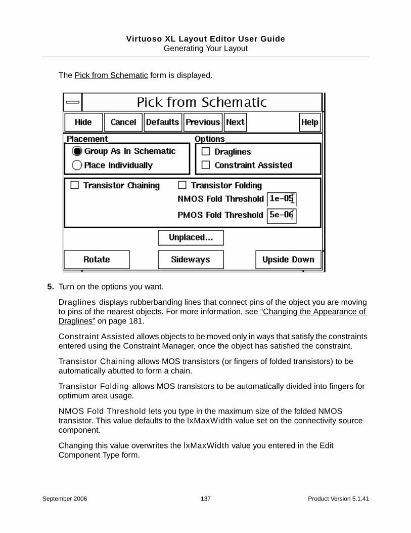
Virtuoso XL Layout Editor User GuideGenerating Your Layout
The Pick from Schematic form is displayed.
5. Turn on the options you want.
Draglines displays rubberbanding lines that connect pins of the object you are movingto pins of the nearest objects. For more information, see “Changing the Appearance ofDraglines” on page 181.
Constraint Assisted allows objects to be moved only in ways that satisfy the constraintsentered using the Constraint Manager, once the object has satisfied the constraint.
Transistor Chaining allows MOS transistors (or fingers of folded transistors) to beautomatically abutted to form a chain.
Transistor Folding allows MOS transistors to be automatically divided into fingers foroptimum area usage.
NMOS Fold Threshold lets you type in the maximum size of the folded NMOStransistor. This value defaults to the lxMaxWidth value set on the connectivity sourcecomponent.
Changing this value overwrites the lxMaxWidth value you entered in the EditComponent Type form.
September 2006 137 Product Version 5.1.41
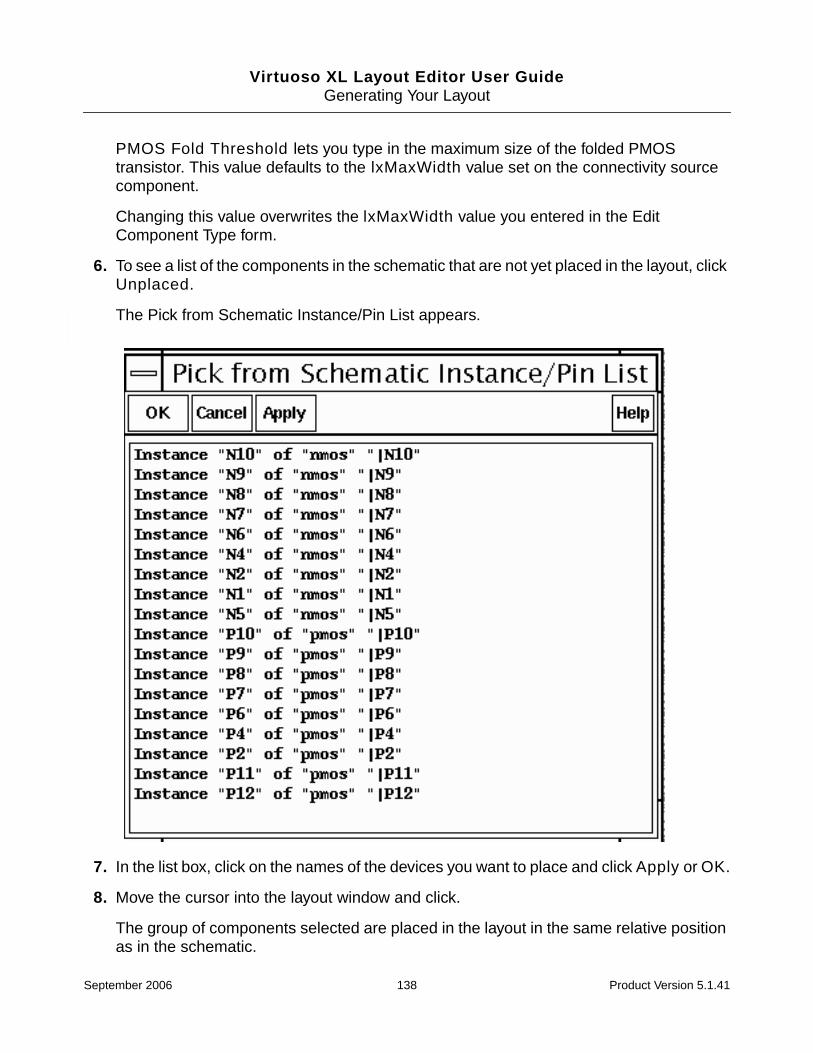
Virtuoso XL Layout Editor User GuideGenerating Your Layout
PMOS Fold Threshold lets you type in the maximum size of the folded PMOStransistor. This value defaults to the lxMaxWidth value set on the connectivity sourcecomponent.
Changing this value overwrites the lxMaxWidth value you entered in the EditComponent Type form.
6. To see a list of the components in the schematic that are not yet placed in the layout, clickUnplaced.
The Pick from Schematic Instance/Pin List appears.
7. In the list box, click on the names of the devices you want to place and click Apply or OK.
8. Move the cursor into the layout window and click.
The group of components selected are placed in the layout in the same relative positionas in the schematic.
September 2006 138 Product Version 5.1.41

Virtuoso XL Layout Editor User GuideGenerating Your Layout
Only components not yet present in the layout can be placed.
Placing Individual Components
To place individual components from the schematic in the layout, follow these steps.
1. In the Pick from Schematic form, turn on Place Individually.
The Pick from Schematic form changes to let you select individual instances.
September 2006 139 Product Version 5.1.41

Virtuoso XL Layout Editor User GuideGenerating Your Layout
Note: The Place Individually option does not allow you to chain devices. TransistorChaining is available only with the Group As In Schematic option.
2. In the schematic, click on the component or group of components you want to place inthe layout.
To select multiple components, click on the first object to select it and Shift-click on theother objects or click and drag over the objects. You can deselect objects usingControl-click.
Selected objects in the schematic remain highlighted until they are deselected or placedin the layout.
You cannot select objects in the schematic if objects with the same name are alreadypresent in the layout.
3. To automatically fold MOS devices into divided fingers for optimum are usage turn on theTransistor Folding option.
NMOS Fold Threshold lets you type in the maximum size of the folded NMOStransistor. This value defaults to the lxMaxWidth value set on the connectivity sourcecomponent.
PMOS Fold Threshold lets you type in the maximum size of the folded PMOStransistor. This value defaults to the lxMaxWidth value set on the connectivity sourcecomponent.
Important
When the Transistor Folding option is turned on the device properties do notappear at the bottom of the Pick from Schematic form. If you need to update any ofthe device properties turn off Transistor Folding.
4. Select Unplaced to view the Pick from Schematic Instance/Pin List. Select the pin orinstance and click Apply. The pin or instance is selected in the schematic window.
5. Move the cursor into the layout window and the Pick from Schematic form updates withthe Library, Cell, View, and InstName.
The Pick from Schematic form updates to show the parameters associated with thecomponent currently being placed.
6. The component to be placed first is highlighted in the schematic in the color assigned tothe hilite drawing2 layer. Selected instances that have not yet been placed arehighlighted in the color assigned to the hilite drawing layer.
The outline of the component follows the cursor in the layout. Draglines showingconnectivity to already placed components follow the component outline.
September 2006 140 Product Version 5.1.41

Virtuoso XL Layout Editor User GuideGenerating Your Layout
7. Turn on the options you want.
8. Click in the layout window to place the highlighted instance or pin.
Generating Pins
When you select a pin to place in your design the pin options are updated on the Pick FromSchematic form.
1. If the components you selected are pins, the Pick from Schematic form changes toinclude pin options (only if you have turned on the Place Individually option) you canchoose.
For more information, see “Pin Options” on page 119.
2. Click in the layout where you want to place the pin.
The pin is created where the image was when you clicked and has the connectivityindicated in the schematic.
3. If you selected more than one pin, without moving the cursor back to the schematic, clickto place the other pins in the layout.
The pins are placed in the layout at the location where you click. The pin currently beingplaced in the layout is always highlighted in the schematic in the color assigned to thehilite drawing2 layer. Selected instances that have not yet been placed arehighlighted in the color assigned to the hilite drawing layer.
You can use the Next and Previous buttons at the top of the Pick from Schematic formto move ahead or back in the order of the list of components you picked.
September 2006 141 Product Version 5.1.41

Virtuoso XL Layout Editor User GuideGenerating Your Layout
Viewing Unplaced Instances/Pins
1. To see a list of all components in the schematic for which there is no corresponding layoutinstance or pin, click Unplaced.
Wires, labels, text, instances with ignore properties, and instances that have alreadybeen placed in the layout are not considered available components and are not shownin this list.
2. Double click on the name of each device in the list and move the cursor to the layout toplace it.
The Pick from Schematic form changes to show available information about thatcomponent.
Constraints entered using the Virtuoso Constraint Manager are observed while you areusing the Pick from Schematic command.
September 2006 142 Product Version 5.1.41

Virtuoso XL Layout Editor User GuideGenerating Your Layout
3. To exit this command, click Cancel on the Pick from Schematic form.
Note: If you are using inherited connections in your design to assign more than one value toa global net, remember that the netSet properties on schematic instances, which specifythe new value of a global signal, are not copied over with the instance from the schematic tothe layout when you use the Gen From Source, Pick from Schematic, or Update LayoutParameters command.
For more information on inherited connections, see “Overview of Inherited Connections” inthe Inherited Connections Flow Guide.
Viewing in Place
1. Select Edit – Pick From Schematic.
2. Move your cursor into the schematic window and select Design – Hierarchy –Descend Read.
3. In the schematic select a device to descend into.
4. Select Hide in the Descend form.
5. In the Descend form change the View Name to schematic and click OK.
The window banner updates in the schematic window.
6. In the Pick From Schematic form select Unplaced.
7. Select an instance or pin in the Pick From Unplaced Instance/Pin form.
8. Click Apply.
9. Place the instance/pin in the layout window.
Using CDF Callbacks with Pick From Schematic
Pick From Schematic applies all callbacks before any instance is created. The entire list ofparameters found on the connectivity source instance (including the adjusted folding,sfactor, or lxCombination parameter) are used to call the CDF; the resulting list ispassed to the layout instance.
September 2006 143 Product Version 5.1.41

Virtuoso XL Layout Editor User GuideGenerating Your Layout
Cloning
Cloning is the ability to replicate a section of the layout that is associated with a section of theschematic in such a way that the new piece of layout material can be placed at more than onelocation, with each part preserving the hierarchical structure of the design.
Cloning can help you lay out
■ Datapath bit slices, datapath and memory control blocks with identical logic cones,programmable logic structures, and other arrayed and iterated structures in device andgate-level custom digital design.
■ Groups of analog/mixed signal components with identical constraints (for example,current mirrors, cascode stages, differential pairs, and other isomorphic structures).
■ Instances of the same symbol master – or instances with the same logic but with differingparameters and hence a different symbol master – that have a flat layout representation
Cloning differs from copying in that the cloned structure maintains its schematiccorrespondence and inherits connectivity information.
The section of the schematic or layout that is used as a template for the clone is called theclone source. The section of the schematic that is to be implemented by replicating thesource is the clone target. The result of replicating the clone source to implement the clonetarget is the clone.
You can use multiple connectivity sources and multiple layout cellviews to create clones usingdevices, pins, and (if selected from the layout window) interconnect structures such as wiresand path shapes. You can also clone components that are implemented as one-to-manyrelationships defined using the mfactor property on a schematic instance. For moreinformation, see “Cloning Mfactored Components” on page 145.
Note: You cannot use structures in the layout that use many-to-one mapping as theconnectivity source for cloning. If you select a many-to-one structure to use as a connectivitysource, a warning appears in the CIW explaining the error and the structure is not selected.
Exact and Non-Exact Matches
To clone components, you select the source structure to be replicated and the softwaresearches for target structures which match that source. You can specify whether potentialtargets must match the source exactly or whether the match can be non-exact.
■ Exact matches must match in terms of instance master, instance parameters andtopological structure.
September 2006 144 Product Version 5.1.41
Virtuoso XL Layout Editor User GuideGenerating Your Layout
■ Non-exact matches can tolerate differences in pin permutation, parameters, andconnectivity between the target and the source.
For information on how the cloning engine finds matching targets, see the Cloning form.
For information on troubleshooting cloning, see “Problems with Cloning” on page 455.
Cloning Mfactored Components
The cloning functionality handles one-to-many relationships defined using the mfactorproperty on a schematic instance.
For example, if you have a schematic component with an mfactor of 100, you can choose tenof these components, hook them up as required in the layout window, and then clone theresulting structure ten times to generate all of the mfactored component instances.
You can clone mfactored components both partially and in their entirety across multiplehierarchy levels, including source structures that include folded and abutted devices. Whenyou select a folded instance, all of the other folded legs of the regular device or mfactoreddevice must also be part of the selection.
Important
When cloning mfactored devices that are partially implemented in the layout, youmust select the clone source from the layout window.
The examples below illustrate what the cloning functionality considers to be valid targets fora number of different mfactored source structures.
Example 1: Mfactored component instance
If the clone source is an mfactored component instance (for example, an NMOS instance withm=2), then a valid clone target is also an mfactored component instance; for example,another nmos instance also with m=2.
Schematic Layout
September 2006 145 Product Version 5.1.41

Virtuoso XL Layout Editor User GuideGenerating Your Layout
Example 2: Mfactored component instance partially realized in the layout
If the clone source is one or more of an mfactored component instance that is partiallyrealized in the layout, then a valid clone target is the remaining components in the mfactoredinstance.
Important
You must select the clone source in the layout window because of the one-to-manyrelationship.
Clone Source
Clone Target
Schematic Layout
Clone Source
Clone Target
MN1m=2
MN1.1 MN1.2
MN2m=2
MN2.1 MN2.2
MN1m=4
MN1.1 MN1.2
MN1m=4
MN1.3 MN1.4
September 2006 146 Product Version 5.1.41
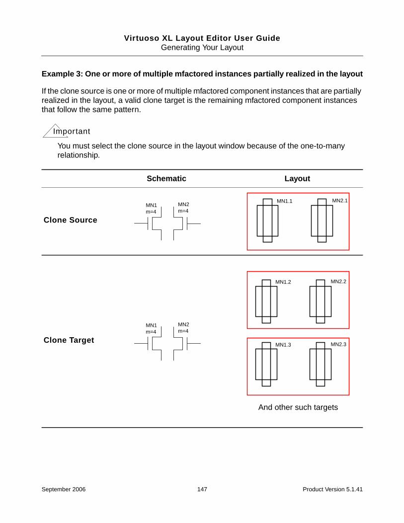
Virtuoso XL Layout Editor User GuideGenerating Your Layout
Example 3: One or more of multiple mfactored instances partially realized in the layout
If the clone source is one or more of multiple mfactored component instances that are partiallyrealized in the layout, a valid clone target is the remaining mfactored component instancesthat follow the same pattern.
Important
You must select the clone source in the layout window because of the one-to-manyrelationship.
Schematic Layout
Clone Source
Clone Target
MN1m=4
MN2m=4
MN1.1 MN2.1
MN1m=4
MN2m=4
MN1.2 MN2.2
MN1.3 MN2.3
And other such targets
September 2006 147 Product Version 5.1.41

Virtuoso XL Layout Editor User GuideGenerating Your Layout
Example 4: Mfactored component instance with other component instances
If the clone source is an mfactored component instance along with other componentinstances, a valid clone target is any other identical configuration with mfactored componentinstances which have the same mfactor value.
Example 5: One or more of an mfactored component instance partially implemented inthe layout along with other component instances
If the clone source is one or more of an mfactored component instance that is partiallyimplemented in the layout along with other component instances, valid clone targets are any
Schematic Layout
Clone Source
Clone Target
MN1m=2
MN2 MN3
MN1.1 MN1.2
MN2 MN3
MN2m=2
MN5 MN6
MN2.1 MN2.2
MN5 MN6
September 2006 148 Product Version 5.1.41
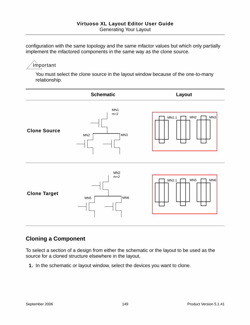
Virtuoso XL Layout Editor User GuideGenerating Your Layout
configuration with the same topology and the same mfactor values but which only partiallyimplement the mfactored components in the same way as the clone source.
Important
You must select the clone source in the layout window because of the one-to-manyrelationship.
Cloning a Component
To select a section of a design from either the schematic or the layout to be used as thesource for a cloned structure elsewhere in the layout,
1. In the schematic or layout window, select the devices you want to clone.
Schematic Layout
Clone Source
Clone Target
MN1m=2
MN2 MN3
MN1.1 MN2 MN3
MN2m=2
MN5 MN6
MN2.1 MN5 MN6
September 2006 149 Product Version 5.1.41

Virtuoso XL Layout Editor User GuideGenerating Your Layout
Important
You can select the connectivity source from either the layout cellview or theschematic or another Virtuoso XL source cellview using single or area selection. Ifthe structure to be cloned has been routed, you must select the structure from thelayout view so that all of the required components and interconnects are selected.Selecting the source from the schematic clones only the components and theirrelative placement, and not the routing or interconnects. If the structure you want toclone is a partially implemented mfactored component, then you must select it in thelayout window.
2. In the layout window menu bar, select Create – Clone.
The CIW prompts you to select a connectivity source.
3. In the schematic or layout window, press Return to confirm your selection.
September 2006 150 Product Version 5.1.41

Virtuoso XL Layout Editor User GuideGenerating Your Layout
The Cloning form is displayed.
4. Set the Target Schematic and the Target Layout to the correct cellviews.
Note: The target structure (components and interconnects) must not exist in the layoutview at the time of cloning, otherwise the cloning command generates a message statingthat the target structure is incorrectly or partially implemented. If the target structure hasalready been generated in the layout, delete it prior to cloning.
September 2006 151 Product Version 5.1.41

Virtuoso XL Layout Editor User GuideGenerating Your Layout
5. Choose whether you want to search for matches in the Entire Target Schematic or onlythe Selected Set.
6. Choose the criteria you want to use to find matches from the Find Match Targets usingsection.
For more information on these options, see the Cloning form.
7. Click Find Matching Targets.
Targets that match the specified criteria are listed in the Unplaced pane.
8. Select one or more devices from the Unplaced list box and click Clone.
9. Choose the placement options (Rotate, Flip Horizontal, Flip Vertical, and Draglines)that affect the placement or appearance of the clone.
For more information on draglines, see “Changing the Appearance of Draglines” onpage 181.
10. Click in the layout window to place the cloned structure where you want it.
The cloned structure is placed in the layout.
11. If you selected more than one target structure, click Clone on the Cloning form and movethe cursor to the layout window again to place the next target.
The outline of the layout structure follows the cursor. When you click, the cloned structureis placed in the layout. The Placed list box lists all of the cloned devices.
Modifying the Correspondence
When searching for matching targets during cloning, Virtuoso XL does not consider therelative placement of instances in the source structure as long as swapping these instancesdoes not change the source topology. Consequently, the relative placement of instances in atarget can differ significantly from the source.
The Modify Correspondence form lets you change the relative placement of instances in thetarget structure manually by changing the correspondence of the individual instances in thesource and the target. When you modify the correspondence manually, Virtuoso XL checksthat the connectivity of the structure remains valid before allowing you to place the clone.
To modify the correspondence of source and target instances,
1. Create a list of matching targets by following steps 1-7 described in “Cloning aComponent” on page 149.
September 2006 152 Product Version 5.1.41

Virtuoso XL Layout Editor User GuideGenerating Your Layout
2. Select an entry in the Unplaced list box and click Modify.
The Modify Correspondence form is displayed.
The instances in the source structure are listed under Connectivity Source. The list isread-only. The corresponding instances in the target structure are listed underConnectivity Target.
When you select an instance in the target structure, the corresponding instance in thesource structure is highlighted.
3. To change the correspondence of a single instance, select the instance in theConnectivity Target list and use the arrow buttons to move it up or down in the list.
4. To swap the correspondence of two instances, select the instances and click Swap.
5. When you have finished modifying the correspondence, click OK.
Before accepting the new correspondence, Virtuoso XL checks that the connectivity ofthe structure remains valid correct.
6. In the Cloning form, click Clone and choose the placement options (Rotate, FlipHorizontal, Flip Vertical, and Draglines) that affect the placement or appearance ofthe clone.
7. Move the cursor into the layout window to view the clone.
❑ If you are happy with the structure, click to place it in the layout.
❑ If you want to modify the structure further, click Modify in the Cloning form andrepeat steps 2-6.
September 2006 153 Product Version 5.1.41

Virtuoso XL Layout Editor User GuideGenerating Your Layout
Important
You must always click Clone in the Cloning form before placing a clone. Thisensures that the structure placed reflects all of the changes you made in the ModifyCorrespondence form.
Cloning a Group of Components
To clone a group of components,
➤ Create a cell containing all the devices and then clone the cell using the procedure in“Cloning a Component” on page 149.
This ensures that all the cells or like circuit sections have the same layout parasiticsassociated with them.
Cloning between Multiple Cellviews
You can place a clone in a different layout from the one in which you selected the source aslong as
■ The second layout has the same connectivity source as the first layout
■ You select all of the source objects from the layout from which you started the Clonecommand (or the corresponding schematic)
To clone an object from one layout cellview into another layout cellview that has the sameconnectivity source,
1. From the layout window menu bar, choose Create – Clone.
2. In the layout window from which you started the Clone command (or the correspondingschematic), select the structure you want to replicate (the connectivity source) and pressReturn.
The Cloning form is displayed.
3. Open the target layout window and select Tools – Layout XL.
4. From the Virtuoso XL layout window menu bar, choose Connectivity – Update –Source.
The Define Connectivity Reference form is displayed.
5. In the Define Connectivity Reference form, specify the schematic that you want to useas the connectivity source for the new layout and click OK.
September 2006 154 Product Version 5.1.41

Virtuoso XL Layout Editor User GuideGenerating Your Layout
6. In the Cloning form, change the Target Layout to the second layout window.
7. Click Find Matching Targets.
8. Select devices from the Unplaced list box.
9. Click Clone.
10. Click in the layout to place the cloned structure.
Creating Correspondence Points
Correspondence points are matching pairs of locations in the schematic. You definecorrespondence points to help you locate the structures you want to clone. Once you definethe correspondence points, they are highlighted in bright colors.
You select pairs of items – for example, R1 and R7 – to be stored in a correspondence pointsfile, a standard text file containing net and device names. You can create any number of fileswith different names and then specify in the Correspondence Points form which one you want.
To create a correspondence points file,
1. From the layout window menu bar, choose Create – Clone.
The Cloning form is displayed.
2. Turn on Correspondence File.
The Correspondence File field becomes active.
3. Type the name of the correspondence file you want to create and click Create.
The Correspondence Pairs form is displayed. The Working File field displays the nameof the correspondence points file displayed in the Cloning form.
4. Click Add.
September 2006 155 Product Version 5.1.41

Virtuoso XL Layout Editor User GuideGenerating Your Layout
The Add Correspondence Pairs form is displayed.
5. Type the component names or click Set By Cursor and select in the schematic thenames of the two components you want to correspond.
6. Click Apply.
The information is added to the end of the correspondence file you specified. Informationat the end of the file is the most recent information and overrides information earlier inthe file.
Displaying Correspondence Points
To display a specific correspondence point defined in the correspondence points file,
1. From the layout window menu bar, choose Create – Clone.
The Cloning form is displayed.
2. Turn on Correspondence File.
The Correspondence File field becomes active.
3. Type the name of the correspondence file you want to display.
4. Click Display.
September 2006 156 Product Version 5.1.41

Virtuoso XL Layout Editor User GuideGenerating Your Layout
The Display Specific Correspondence Components form is displayed.
5. Turn on Source or Target to choose the point you want to display.
6. Type the name of the point you want to display or click on it in the schematic or layout.
7. Click Apply.
The correspondence points you specified are highlighted in the schematic.
To display all the points in the correspondence points file,
➤ In the Correspondence Pairs form, click Display All Pts.
All the correspondence points in the correspondence points file are highlighted in theschematic.
To remove the highlighting on all the points in the correspondence point file
➤ In the Correspondence Pairs form, click Clear All Pts.
The highlights are removed from correspondence points in the schematic.
Removing Correspondence Points
To remove correspondence points,
1. From the layout window menu bar, choose Create – Clone.
The Cloning form is displayed.
2. Turn on Correspondence File.
The Correspondence File field becomes active.
3. Type the name of the correspondence file you want to change.
4. Click Remove.
September 2006 157 Product Version 5.1.41

Virtuoso XL Layout Editor User GuideGenerating Your Layout
The Remove Correspondence Components form is displayed.
5. Choose whether you want to remove the Source or Target point.
6. Type the name of one of the correspondence points in the Name Of Point field.
7. Click Apply.
The correspondence points are removed from the bottom of the correspondence file.
If a correspondence point has several corresponding points, all of its correspondencepoints are removed.
Online Forms
■ Add Correspondence Pairs on page 159
■ Cloning on page 159
■ Correspondence Pairs on page 161
■ Define Connectivity Reference on page 161
■ Display Specific Correspondence Components on page 162
■ Import XL Netlist on page 162
■ Layout Generation Options on page 163
■ Open File on page 167
■ Pick from Schematic on page 168
■ Remove Correspondence Components on page 170
■ Set Pin Label Text Style on page 170
■ Startup Option on page 172
September 2006 158 Product Version 5.1.41
Virtuoso XL Layout Editor User GuideGenerating Your Layout
Add Correspondence Pairs
Name in Connectivity Source lets you type the name of the connectivity point you want tobe the source when you click Apply.
Name in Connectivity Target lets you type the name of the connectivity point you want tobe the target when you click Apply.
Set By Cursor lets you indicate by clicking on a point with the cursor the name of the pointyou want added when you click Apply.
Cloning
Options
Draglines controls whether draglines are displayed during the Clone command. Bydefault, the draglines indicate connections from the pins of the object you are moving topins of the nearest objects.
For information on how to change the display of draglines, see the Draglines optionsdescribed in “Layout XL Options” on page 65.
Correspondence File enables the text field where you can specify the name of thecorrespondence file.
Create opens the Correspondence Pairs form, which lets you edit correspondencepairs.
Target Schematic contains the circuit to be replicated by the Clone command. The defaultvalue for this field is the connectivity source from the cellview pair which launched the Clonecommand.
Target Layout is the cellview where the clone is to be placed. The default value for this fieldis the layout from which the Clone command was launched.
Find Matching Targets on
Entire Target Schematic searches the entire schematic to find matching targets.
Selected Set on Target Schematic searches only the selected set to find matchingtargets.
Find Matching Targets using
September 2006 159 Product Version 5.1.41
Virtuoso XL Layout Editor User GuideGenerating Your Layout
Permutation means that pin permutability is taken into account when searching formatching targets. If permuting the pins on a device results in a match, then that match isreported.
Exact Parameter Match requires that the parameter values on the target componentsmatch exactly the parameter values on the source components.
Exact Connectivity Match requires that the connectivity of the target componentsmatches exactly the connectivity of the source components. If you switch off this option,the software also considers non-exact connectivity matches. You can control the qualityand number of non-exact connectivity matches reported using the following options.
Maximum partial net matches sets the maximum number of source nets whichcan be unmatched in a target structure. If a target structure has more than thespecified number of unmatched nets, it is not reported.
Tip
If you set the value for Maximum partial net matches too high, it can prevent thesoftware from finding better target structures with fewer partial nets. To avoid thissituation, either lower the Maximum partial net matches value or limit the searchto a selected set of instances.
Allowed partial net names specifies the names of source nets that are permittedto be unmatched in the target structure. You can use regular expressions to specifymultiple net names with common elements. If a source net name is not listed (ordoes not match one of the regular expressions specified), then the net must bematched exactly in the target structure.
Maximum found matches sets the maximum number of non-exact targetmatches reported.
Find Matching Targets invokes the pattern matching.
Unplaced lists the components or structures chosen as target structures for cloning butwhich are not placed in the target layout window.
Placed lists all the target structures that have been cloned and placed in the target layoutwindow.
Modify brings up the Modify Correspondence form where you can change thecorrespondence between the instances in source and target structures.
Clone lets you place in the layout window the structure selected in the Unplaced pane.
September 2006 160 Product Version 5.1.41
Virtuoso XL Layout Editor User GuideGenerating Your Layout
Rotate rotates the component or structure to be placed through 90 degreescounterclockwise.
Flip Horizontal mirrors the component or structure to be placed on its y axis.
Flip Vertical mirrors the component or structure to be placed on its x axis.
Correspondence Pairs
Working File lets you accept the default name of the correspondence points file(lvs_corr_file) or type a different name.
Add opens a form that lets you add correspondence points to the correspondence points file.
Remove opens form that lets you delete correspondence points from the correspondencepoints file.
Display opens a form that lets you display individual correspondence points from thecorrespondence points file.
Display All Pts opens a list box that shows all the correspondence points in thecorrespondence points file.
Clear All Pts clears all correspondence points from the correspondence points file.
Define Connectivity Reference
Source specifies the connectivity source for the design: Schematic, Netlist, or None.
Library specifies the name of the library containing the connectivity reference.
Update layout cellviews hierarchically descends into a hierarchical layout cellviewand updates the library setting for any for any lower-level cellviews in accordance withthe library name specified for the top-level cell. The system traverses the entire hierarchyaccessible from the current cellview.
Note: Lower-level cellviews updated in this way are not saved until you confirm thatyou want to do so at the end of the session
This option is available only when Source is set to Schematic.
Cell lets you type in the name of the cell you want to use as a connectivity reference.
View defaults to schematic. You can type in a different view name.
September 2006 161 Product Version 5.1.41
Virtuoso XL Layout Editor User GuideGenerating Your Layout
Browse displays the Library Browser, which lets you click on names to fill in the form. Evenif the Library Browser is already open, you must click Browse if you want the names you clickon to appear in the form.
Sel by Cursor lets you specify the schematic or layout to use by clicking in the open cellviewwindow.
Top Cell (appears only if you choose Netlist as the source) lets you enter the top cell of thenetlist.
Display Specific Correspondence Components
Identify Connectivity
Source sets the software to display the connectivity point identified as the source whenyou click Apply.
Target sets the software to display the connectivity point identified as the target whenyou click Apply.
Name Of Point lets you type the name of the point you want displayed when you click Apply.
Set By Cursor lets you indicate by clicking on a point with the cursor the name of the pointyou want displayed when you click Apply.
Import XL Netlist
Netlist File specifies the name of the file to use as a netlist.
Copy copies the imported netlist file to the destination library location.
Link links the imported netlist file to the destination library location.
Move moves the imported netlist file to the destination library location.
Library specifies the name of the library in which you want to put the netlist.
Cell specifies the name of the cell in which you want to put the netlist.
View specifies the view name in which you want to store the netlist.
Browse opens the Open File form if your cursor is in the Netlist File text field. From theOpen File form, you can choose any file to which you have access. If your cursor is in theLibrary or Cell or View fields, the Browse button opens the Library Browser form, fromwhich you can choose a library, cell, and view.
September 2006 162 Product Version 5.1.41

Virtuoso XL Layout Editor User GuideGenerating Your Layout
Format is either CDL or SPICE.
Check allows you to check the netlist for any errors before generating your layout. Any errorsare displayed in the CIW, along with a message stating that there are syntax errors which maybe the result of unsupported syntaxes.
Layout Generation Options
Generate
I/O Pins generates all the pins specified in the I/O Pins section of the form. Thegenerated pins are automatically snapped to the placement grid
Instances generates all the instances in the schematic that do not have “ignore”properties attached to them.
Boundary generates a design boundary using the layer and size information youspecify in the Boundary section of this form.
Transistor Chaining enables the abutment of ordered lists of MOS transistors intochains and generates them in the design.
Transistor Folding lets you split devices into fingers which keeps the gate width fromgoing beyond the manufacturing foundry specification size.
Preserve Mappings, when switched on, preserves previous many-to-many, many-to-one, and one-to-many mappings. By default these are ignored.
I/O Pins
Apply applies the specified Defaults to all of the pins displayed in the list box.
Term Name is the schematic terminal name. Where terminal and net (wire) names aredifferent in the schematic, Virtuoso XL creates pins in the layout that have the samename as the schematic terminal but the net associated with the pin in the layout is thename of the wire attached to the terminal in the schematic. If there is no explicit wire labelin the schematic, both the pin and the net name in the layout are the same as theschematic terminal (default behavior).
Net Name is the net associated with the pin in the layout that is the name of the wireattached to the terminal in the schematic. If there is no explicit wire label in the schematic,both the pin name and the net name in the layout are the same as the schematicterminal.
Pin Type specifies the type of pin to be generated.
September 2006 163 Product Version 5.1.41
Virtuoso XL Layout Editor User GuideGenerating Your Layout
❑ Geometric specifies that a geometric pin is to be generated. You must also choosethe layer on which to create the pin from the Layer/Master cyclic field.
❑ Symbolic specifies that a symbolic pin is to be generated. You must also choosethe name of a symbolic pin master from the Layer/Master cyclic field.
Note: If you choose this option, the Height field is disabled because symbolic pinsare square. If there are no symbolic pins defined in the technology file, this option isnot available.
Layer/Master lets you choose the layer when generating geometric pins or the mastercellview when generating symbolic pins.
❑ For geometric pins, the default is the current drawing layer if it is defined aslxExtractLayer in the technology file. Otherwise, the default is the first layerdefined as lxExtractLayer, and the cyclic field offers only the conductinglayers. If no layers have been defined as lxExtractLayer, the cyclic fieldshows all valid layout layers.
❑ For symbolic pins, the field displays the symbolic pin masters defined in thetechnology file. If none are shown, it means there are no symbolic pins defined inthe technology file.
Width specifies the width for each pin. The default is the minWidth property value setfor the current layer in your technology file.
Height specifies the height for each pin. The default is the minWidth property valueset for the current layer in your technology file.
Num specifies how many instances of this pin to create. If you type 0 in this field, the pinis not created.
Create, when switched on, specifies which of the pins listed on the form (based on pinsshown in the schematic) are to be generated in the layout.
Select lets you type in a pin name to select the pin in the list box.
Number Selected shows you the number of pins that are currently selected in the list box.
Add a Pin adds a pin to the list box after you click OK.
Update changes the Pin Type, Layer/Master, Width, Height, Num, and Create settingsfor one or more selected pins.
Pin Type specifies the type of pin to be updated.
Geometric specifies that a geometric pin is to be updated. You must also choosethe layer on which to update the pin from the Layer/Master cyclic field
September 2006 164 Product Version 5.1.41

Virtuoso XL Layout Editor User GuideGenerating Your Layout
Symbolic specifies that a symbolic pin is to be generated. You must also choosethe name of a symbolic pin master from the Layer/Master cyclic field.
If you choose this option, the Height field is disabled because symbolic pins aresquare. If there are no symbolic pins defined in the technology file, this option is notavailable.
Layer/Master lets you choose the layer when updating geometric pins or the mastercellview when updating symbolic pins.
❑ For geometric pins, the default is the current drawing layer if it is defined aslxExtractLayer in the technology file. Otherwise, the default is the first layerdefined as lxExtractLayer, and the cyclic field offers only the conductinglayers. If no layers have been defined as lxExtractLayer, the cyclic fieldshows all valid layout layers.
❑ For symbolic pins, the field displays the symbolic pin masters defined in thetechnology file. If none are shown, it means there are no symbolic pins defined inthe technology file.
Width specifies the width for each updated pin. The default is the minWidth propertyvalue set for the current layer in your technology file.
Height specifies the height for each updated pin. The default is the minWidth propertyvalue set for the current layer in your technology file.
Num specifies how many instances of this pin to update. If you type 0 in this field, no pinsare updated.
Create, when switched on, specifies which of the pins listed on the form (based on pinsshown in the schematic) are to be updated in the layout.
Pin Label Shape defines the type of label generated when you create a pin. This setting ishonored by the Gen From Source and Pick From Schematic commands.
Label creates a label on the layer specified on the Set Pin Label Text Style form.
Text creates text on the layer specified on the Set Pin Label Text Style form. If the text isnot visible, turn on the Pin Names option in the Display Options form.
None does not create a label or text for the pins.
Pin Label Options opens the Set Pin Label Text Style form, which lets you set the size,font, style, justification and orientation of the label lettering and the drawing or pin layeron which the labels are shown.
Boundary
September 2006 165 Product Version 5.1.41

Virtuoso XL Layout Editor User GuideGenerating Your Layout
Layer specifies the layer on which you draw the cell boundary. The default is the entry layerdefined by the initBoundaryLayer environment variable.
Shape lets you set the shape to Rectangle or Polygon.
■ If you set Shape to Rectangle, if you do not want the design boundary’s left andbottom sides located at the default position, you can enter new values in the Left andBottom fields.
Left lets you enter a value on the x axis to situate the left side of the rectangle.
Bottom lets you enter a value on the y axis to situate the bottom of the rectangle.
Additionally, with Shape set to Rectangle, the Boundary Area Estimation controlsare also displayed. Use these to control how Virtuoso XL estimates the area required forthe design.
Utilization (%) specifies the percentage of area within the cell boundary that youwant to fill. The default is 25%.
Important
When the Transistor Chaining and Transistor Folding options are switched on,the utilization is applied only after chaining and folding is complete in order tocalculate the size of the PR boundary accurately.
Aspect Ratio W/H is the width-to-height ratio of the design boundary. For example,a value of 1 specifies a square boundary, 0.5 specifies a boundary twice as high asit is wide, and 2 specifies a boundary twice as wide as it is high.
Area Calculation controls which shapes are used to calculate the contents of thedesign and, in turn, the area required to accommodate them.
❍ PRBoundary Based uses the place and route boundaries of the individuallower-level cells to calculate the area. The place and route boundary is apolygon derived by merging the areas of all of the shapes found on layer-purpose pair (prBoundary boundary). If there are no shapes on(prBoundary boundary), the estimator looks at (prBoundary drawing);if there are no shapes on either of those, the estimator looks at (instancedrawing).
❍ BBox Based uses the bounding boxes of cellview masters to calculate thearea. The derived bounding box is typically larger than the place and routeboundary in standard cells because of metal overhangs and presence of textdisplay objects and labels. This can result in pessimistic area estimates withvalues much higher than would be expected for a compact layout.
September 2006 166 Product Version 5.1.41

Virtuoso XL Layout Editor User GuideGenerating Your Layout
❍ User Defined lets you specify your own boundary area estimation function inthe text field provided. Type in only the name of the function; the cellview ID ispicked up automatically from the currently-open cellview.
For more information on defining your own area estimation function, see “User-Defined Area Estimation Functions” on page 107.
■ If you set Shape to Polygon, the form changes to let you define the number and lengthof the sides.
Points is a field that lets you enter the points where the sides meet. For example,the format for a rectangle is:
(0 0) (10 0) (10 10) (0 10)
Load Template File for Layout Generation allows you to load an ASCII template file intothe Layout Generation Options form.
Browse opens the Open File form, which allows you to specify a file that contains storedlayout generation options.
Load loads the stored layout generation options into the Layout Generation Optionsform.
You can set an environment variable, templateFileName, to always load the name of atemplate you specify.
Modify Correspondence
Connectivity Source lists the instances in the source structure. The list is read-only.
Connectivity Target lists the instances in the target structure. When you select an instancein the target structure, the corresponding instance in the source structure is highlighted in theConnectivity Source list.
You change the correspondence of an instance by selecting it in the Connectivity Target listand moving it up or down in the list using the arrow buttons. You can also swap thecorrespondence of a pair of target instances using the Swap button.
When you click OK, Virtuoso XL checks that connectivity is still correct before accepting thenew correspondence.
Open File
Name lets you specify the name of a template file.
September 2006 167 Product Version 5.1.41

Virtuoso XL Layout Editor User GuideGenerating Your Layout
Pick from Schematic
Placement
Group As In Schematic lets you move a group of components together into the layoutin the same relative position as in the schematic. In this mode, you cannot change theparameters on the components.
Place Individually lets you move each component individually.
Note: The chaining option is not available when using the Place Individually option. Tochain devices interactively, use the Edit – Transistor Chaining command.
Options
Draglines controls whether draglines are displayed during the Pick From Schematiccommand. By default, the draglines indicate connections form the pins of the object youare moving to pins of the nearest objects.
For information on how to change the display of draglines, see the Draglines optionsdescribed in “Layout XL Options” on page 65.
Constraint Assisted, when active, allows objects to be moved only in ways that satisfythe constraints entered using the Constraint Manager, once the object has satisfied theconstraint.
Transistor Chaining is active only with the Group As In Schematic option. TransistorChaining allows a set of MOS transistors (or fingers of folded transistors) to be automaticallyabutted to form a chain. Transistors to be abutted must be set up for abutment first. For moreinformation, see “Setting Up Cells for Abutment” on page 73.
Transistor Folding, when active, allows MOS transistors to be automatically divided intofingers for optimum area usage. The Group As In Schematic option makes the TransistorChaining and Transistor Folding options available. Transistor Folding operatesindependently from Transistor Chaining. The Place Individually option makes availableonly the Transistor Folding option.
NMOS Fold Threshold, when Transistor Folding is active, lets you type the maximumsize of the folded NMOS transistor. This value defaults to the lxMaxWidth value set onthe connectivity source component.
Changing this value overwrites the lxMaxWidth value you entered in the EditComponent Type form associated with the Place – Component Types command.
September 2006 168 Product Version 5.1.41

Virtuoso XL Layout Editor User GuideGenerating Your Layout
PMOS Fold Threshold, when Transistor Folding is active, lets you type the maximumsize of the folded PMOS transistor. This value defaults to the lxMaxWidth value set onthe connectivity source component.
Changing this value overwrites the lxMaxWidth value you entered in the EditComponent Type form associated with the Place – Component Types command.
Unplaced opens the Pick from Schematic Instance/Pin List form displaying a list of eachcomponent in the schematic for which there is no corresponding instance or pin in the layout.
When the Place Individually option is active, the form adds the following four fields to thePick from Schematic form displaying information about the components you select forplacement.
LibName displays the name of the library of the component you select from the list ofunplaced components or from the schematic.
CellName displays the cell name of the component you select from the list of unplacedcomponents or from the schematic.
ViewName displays the view name of the component you select from the list of unplacedcomponents or from the schematic.
InstName displays the instance name of the component you select from the list ofunplaced components or from the schematic.
When a component is selected, the form adds additional fields, depending on the componentand its attributes.
Pin Options
When a pin is selected, the form displays the following pin creation options. Generated pinsare automatically snapped to the placement grid in the layout view.
Terminal Name automatically displays the name of the pin first in line to be placed.
Type lets you choose the type of pin to place.
Rectangle Pin lets you create a rectangular pin.
Symbolic Pin changes this form to let you create symbolic pins.
Layer allows you to change the layer purpose pair of the pin that has been selected.
Width allows you to change the width of the pin.
September 2006 169 Product Version 5.1.41

Virtuoso XL Layout Editor User GuideGenerating Your Layout
Height allows you to change the height of the pin.
Create Label attaches a label, showing the terminal name, to the pin.
Display Pin Name Options opens the Set Text Style form, which lets you set the font,height, justification, and orientation of the pin name.
I/O Type assigns a property used by routers to identify the direction of the signal into or outof this pin. The signal can be input, output, inputOutput (bidirectional), switch (carries dataeither in or out, but not simultaneously), or jumper (passes data through this pin).
Access Direction assigns a property used to identify the part of the pin to which routers canconnect routing. The access direction can be top, bottom, left, right, any, or none.
When a device is selected, the form displays properties set for that device.
Rotate rotates the component 90 degrees counterclockwise.
Sideways mirrors the component on the y axis (flips it horizontally).
Upside Down mirrors the component on the x axis (flips it vertically).
Remove Correspondence Components
Identify Connectivity
Source sets the software to remove the connectivity point identified as the source whenyou click Apply.
Target sets the software to remove the connectivity point identified as the target whenyou click Apply.
Name Of Point lets you type the name of the point you want removed when you click Apply.
Set By Cursor lets you indicate by clicking on a point with the cursor the point you wantremoved when you click Apply.
Set Pin Label Text Style
Height sets the height of the label in user units (usually microns).
Font sets the text style of the label. The choices are euroStyle, gothic, math, roman,script, stick, and swedish.
September 2006 170 Product Version 5.1.41

Virtuoso XL Layout Editor User GuideGenerating Your Layout
Text Options
Drafting prevents the label from being rotated more than 90 degrees.
Overbar is a display option that determines how text strings containing underscorecharacters are displayed in a layout window.
When the overbar is switched off (default), the software displays underscore characters( _ ) as part of the text string. When the overbar is switched on, the software interpretsunderscore characters in the text string name as toggle switches that control whereoverbars begin and end. Overbars appear above the text string, as shown in theexamples below.
Layer sets the drawing layer on which the labels appear.
Pin Layer sets the pin layer on which the labels appear.
Justification sets the location of the label origin. The origin appears as a small square onthe label when you place or select it. The choices are lowerLeft, centerLeft, upperLeft,lowerCenter, centerCenter, upperCenter, lowerRight, centerRight, and upperRight.
Orientation lets you specify the orientation of the labels. The choices are
Text string Appears in design window as
_abcde abcde
ab_cde abcde
_abc_de abcde
ab_cd_ef_gh_ij abcdefghij
Value Meaning
R0 No rotation
R90 Rotate 90 degrees
R180 Rotate 180 degrees
R270 Rotate 270 degrees
MX Flip upside down
MY Flip sideways
MXR90 Flip upside down and rotate 90 degrees
September 2006 171 Product Version 5.1.41

Virtuoso XL Layout Editor User GuideGenerating Your Layout
Startup Option
Create New opens the Create New File form to let you type the name of a new layout viewfor your Virtuoso XL design.
Open Existing opens the Library Browser to let you choose the name of an existing layoutview for your Virtuoso XL design.
Template File
All allows you to select all options so that the boundary, pin, partition, and row informationcan be saved to a template file.
Boundary allows you to save boundary information to a template file.
I/O Pins
Locations allows you to save the location of the pins from the Pin Placement form.
Constraints allows you to save the edge, order, and pitch information from the PinPlacement form.
Rows allows you to save the row information from the Placement Planning form.
Partitions allows you to save the partition information from the Partitioning form.
Template file name allows you to type in a name for the template file, ex.row.lxt.
MYR90 Flip sideways and rotate 90 degrees
Value Meaning
September 2006 172 Product Version 5.1.41
Virtuoso XL Layout Editor User Guide
7Editing Your Layout
This chapter shows you how to use the Virtuoso® XL Layout Editor to edit the placement ofcomponents in the layout and how to add additional components. This chapter discusses thefollowing topics.
■ Identifying Incomplete Nets on page 174
■ Moving Objects Manually on page 177
■ Swapping Components on page 182
■ Permuting Component Pins on page 183
■ Using Device Locking on page 187
■ Component Types on page 188
■ Using Transistor Folding on page 193
■ Adding Pins to a Layout on page 199
■ Assigning Pins to a Net on page 201
■ Using Edit-In-Place on page 202
For information on defining pin groups for external connections (must-connect groups), see“Using Connectivity” in the Virtuoso Layout Editor User Guide.
For information about using constraints to restrict the placement of objects, see the VirtuosoConstraint Manager User Guide.
For information on Virtuoso XL forms, see “Online Forms” on page 203.
September 2006 173 Product Version 5.1.41

Virtuoso XL Layout Editor User GuideEditing Your Layout
Identifying Incomplete Nets
To view flight lines (lines that show uncompleted electrical connections between componentterminals, pins, and shapes in each net), follow these steps.
Note: Turn off the connectivity extractor by
■ Turning off the Connectivity Extractor option in the Layout XL Options.
■ Setting the extractEnabled environment variable to nil in the .cdsenv file.
You will not be able to see flight lines.
1. From the layout window, choose Connectivity – Show Incomplete Nets.
The Show Incomplete Nets form is displayed.
September 2006 174 Product Version 5.1.41

Virtuoso XL Layout Editor User GuideEditing Your Layout
By default all incomplete nets are not displayed with flight lines until you select either asingle net, a group of nets, or all nets and click Apply in the Show Incomplete Netsform.
Note: You can set an environment variable, showIncNetEnable, that causes flightlines to appear as soon as the design is opened. The default setting for this variable isnil, so flight lines showing incomplete nets do not appear until you choose the ShowIncomplete Nets command, select the incomplete nets and click Apply.
The Show Incomplete Nets form lists all of the incomplete nets in the design. Thisincludes
❑ Unrouted instance terminals with no pins
❑ Unrouted instance terminals with pins that are not extractable
❑ Instance terminals with dangling must-join instance pins.
Use the Show Incomplete Nets form to display flight lines only for the nets you specify orto filter by net name the names of the nets shown.
2. Select the nets to be displayed by clicking on their names in the Incomplete list of netsor by typing the names in the text field. You can click on multiple net names or deselectselected names using Control-click. You can select a range of names in the list byclicking on the top name and then clicking on the bottom name with Shift-click.
You can display nets that have been put into a class. To create a class use the Tools –Constraint Manager form. In the Constraint Manager form change the Select Entityto Support Entities. Click the Classes button and select Create. In the Create Classform, specify the nets to be put into classes and a class name. The class name appearsin the list box.
3. Click Apply.
Flight lines for the nets whose names are highlighted in the list of nets are displayed inthe layout. Where possible, a flight line is drawn between shapes in the layout window.When a flight line starts from a logical object, the line is drawn to the center of theinstance.
The Show Incomplete Nets form reports how many incomplete nets there are in thedesign and how many are displayed.
Note: The Show Incomplete Nets command does not highlight nets that are complete.To highlight a complete net, use the Connectivity – XL Probe command. If you haveselected a complete net and the net becomes incomplete by deleting a path segment,then the net is highlighted.
September 2006 175 Product Version 5.1.41

Virtuoso XL Layout Editor User GuideEditing Your Layout
Zooming In on Flight Lines
1. To zoom in on the flight lines that are displayed, click Zoom.
The flight lines and their surroundings are shown enlarged as much as possibledepending on how many flight lines are shown.
2. To zoom in on each flight line in turn, click Individual Flight Line Segments.
Arrows appear on the form to let you cycle forward or backward through the displayedflight lines.
Virtuoso XL updates flight lines automatically each time you move a component and make orremove a connection.
Assigning Colors to Incomplete Nets
By default, Virtuoso XL uses the colors you assigned to the Layer Selection Window (LSW)entry layers y0 through y9 to show flight lines. If there are more than ten incomplete nets in
September 2006 176 Product Version 5.1.41

Virtuoso XL Layout Editor User GuideEditing Your Layout
the design, the colors recycle. When you choose Show Incomplete Nets, the colors usedare the ones assigned when the command was last used or when the design was last saved.
To assign colors other than the default colors to the flight lines you specify, follow these steps.
1. In the Incomplete nets list box, select the names of the nets whose color you want tochange.
2. In the color choice cyclic field, select the color you want the nets to be.
3. Click Set Color.
The color of the net changes to the color you specified.
To turn off flight lines in the layout window,
➤ From the layout window, choose the Connectivity – Hide Incomplete Nets command.
Tip
If editing commands run slowly while the Show Incomplete Nets command isactive, use the Incomplete Nets form to turn off the display of incomplete nets on allthe nets except the ones you are working on.
Moving Objects Manually
To move objects (devices, pins, or shapes) in the layout window, follow these steps.
1. From the layout window, choose Edit – Move.
The layout window prompts you to select an object to move.
2. Click on the object you want to move in either the layout or the schematic.
Hide Incomplete NetsShow Incomplete Nets
September 2006 177 Product Version 5.1.41

Virtuoso XL Layout Editor User GuideEditing Your Layout
The object is highlighted in both the schematic and layout windows. An outline of theobject appears in the layout window and follows the cursor until you click in the layoutwindow to place the object.
Draglines show connections from pins of the selected object to pins of the nearestinstance or the nearest I/O pin.
For more information, see “Changing the Appearance of Draglines.”
The layout window prompts you to click on the new location in the layout where you wantto place the selected object.
3. Click on the location where you want to place the object.
The object moves to the new location.
Note: If you select a component in the layout or the schematic before you choose theMove command, Virtuoso XL highlights the corresponding component in the schematicor layout.
4. Click on the next object you want to move or press Escape to cancel the command.
Note: Using the Move command cancels any existing commands in the current or in otherwindows.
Moving Objects Using Move Options
When you move objects, you can use the Move form to change
■ The layer of the object you select.
■ The angles at which you can move the object.
■ The presence of draglines on the object as you move it.
■ The orientation of the object you select.
■ The use of placement constraints. For more information, see the Virtuoso ConstraintManager User Guide.
■ The ability to move members of constrained groups individually or together.
To use the Move options form to place components, follow these steps.
1. From the layout window, choose Edit – Move.
2. Press F3.
September 2006 178 Product Version 5.1.41

Virtuoso XL Layout Editor User GuideEditing Your Layout
The Move form is displayed. The Display Draglines, Constraint Assisted Control,and Chain Mode options appear on the Move form only when you are running VirtuosoXL.
3. If you want to change the angle at which you can move an object (any angle, diagonal,orthogonal, horizontal, vertical), choose the angle you want from the Snap Modecyclic field.
4. If you want to change the layer on which a shape is drawn, turn on Change To Layerand choose a new layer from the cyclic field.
The layer is updated when you move the cursor into the layout window.
5. If you want to keep chained devices together as you move them select either All,Selected, Selected Plus Left, or Selected Plus Right.
September 2006 179 Product Version 5.1.41

Virtuoso XL Layout Editor User GuideEditing Your Layout
6. If you want to turn the draglines off or on for an object you move, turn Display Draglinesoff or on.
For more information, see “Changing the Appearance of Draglines” on page 181.
Note: Disabling Display Draglines can speed up the action of the Move command.
7. To move groups of components bound by placement constraints as a unit or individually,turn on together or individually.
If a group of components you move is affected by placement constraints, thoseconstraints are obeyed during the duration of the Move command.
If a single component you move is subject to an unsatisfied Distance, Fixed, or Grouping(with a fence) constraint, and you move it across a coordinate that satisfies theconstraint, the component snaps to that coordinate.
Components restricted by Alignment or Symmetry constraints do not snap to coordinateswhen you move them, but if their constraints have already been satisfied, you can movethem only in ways that do not break the constraints.
In the case of a group constraint with a fence, the Move command lets you move thedevice until it is inside the fence; after that, you cannot move it outside the fence.
8. Use the Delta X/Y fields to type in the coordinates of the selected devices instead ofusing your cursor to move devices. In the Delta X and Y text fields type the amount ofcoordinates to move the devices, and then click Apply XY.
9. To turn off the use of placement constraints for the components you move, turn onignore.
10. To change the orientation of the object, click on the button describing the orientation youwant (Rotate, Sideways, or Upside Down).
The orientation of the object changes when you move your cursor into the layout window.
Note: When you use the Edit – Stretch command with Virtuoso XL running, theDisplay Draglines and the Constraint Assisted Control options also appear on the
September 2006 180 Product Version 5.1.41

Virtuoso XL Layout Editor User GuideEditing Your Layout
Stretch form and work the same way.
Changing the Appearance of Draglines
When using the Create – Pick From Schematic, Create – Clone, Edit – Move, and Edit– Stretch commands, Virtuoso XL displays draglines which connect the pins on the objectto the nearest pins on another object on the net. When you move the object closer to adifferent object on the same net, the lines reconnect to the new object.
Note: This option is available only in Virtuoso XL.
If you need to know more about the potential connections for the instance you are workingon, you can change both the number and the appearance of the draglines using the optionsunder Draglines in the Layout XL Options form.
You can display draglines for all of the connections to the instance you are working on, hidethe draglines for global nets and for power and ground nets, and have each dragline shownin a different color.
September 2006 181 Product Version 5.1.41

Virtuoso XL Layout Editor User GuideEditing Your Layout
Tip
Disabling Display Draglines can speed up the action of the Move command.
Setting the Move Form to Appear Automatically
To set the Move form, or other options forms, to appear each time you use the Movecommand (without having to press F3) follow these steps.
1. From the CIW, choose Options – User Preferences.
The User Preferences form is displayed.
2. Click Options Displayed When Commands Start.
3. Click OK.
The Move form is displayed each time you choose the Move command.
Swapping Components
To swap the location of two components in the layout window, follow the steps below.
1. From the layout window, choose Edit – Other – Swap Components.
2. Click on the first component in the layout window.
Virtuoso XL prompts you to select a second component.
3. Click on the second component in the layout window.
Virtuoso XL switches the locations of the components you selected, but retains theorientation of the component associated with the position.
4. To undo the swap, from the layout window choose Edit – Undo.
5. To swap another two components, choose Edit – Other – Swap Components again.
npn1
npn1
npn2 npn2
September 2006 182 Product Version 5.1.41

Virtuoso XL Layout Editor User GuideEditing Your Layout
Virtuoso XL does not move the connections to the components. If swapping componentscauses shorts, markers show where the shorts are. If swapping components causes openconnections, flight lines show the open connections.
The Swap Components command does not allow you to swap components that are part ofa satisfied constraint (unless the swap maintains the constraint).
Permuting Component Pins
Virtuoso XL lets you permute (exchange the connectivity or net connections of) the pins of acomponent.
Pins to be permuted
■ Must belong to different nets.
■ Must first be defined as permutable terminals. For more information, see “permuteRule”on page 789.
When the Auto Permute Pins option is active (the default setting) in the Virtuoso XL Optionsform, Virtuoso XL automatically permutes pins in a component if doing so corrects a shortcaused by routing when the routing was done interactively (using automatic abutment) ordone while moving or stretching a shape (or using any operation that changes connectivity).
To change the setting of the Auto Permute Pins option, follow these steps.
1. From the layout window, choose Options – Layout XL.
September 2006 183 Product Version 5.1.41
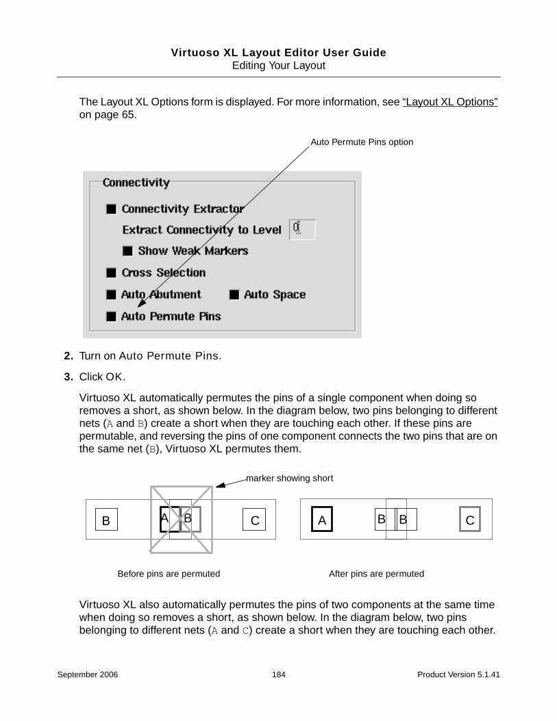
Virtuoso XL Layout Editor User GuideEditing Your Layout
The Layout XL Options form is displayed. For more information, see “Layout XL Options”on page 65.
2. Turn on Auto Permute Pins.
3. Click OK.
Virtuoso XL automatically permutes the pins of a single component when doing soremoves a short, as shown below. In the diagram below, two pins belonging to differentnets (A and B) create a short when they are touching each other. If these pins arepermutable, and reversing the pins of one component connects the two pins that are onthe same net (B), Virtuoso XL permutes them.
Virtuoso XL also automatically permutes the pins of two components at the same timewhen doing so removes a short, as shown below. In the diagram below, two pinsbelonging to different nets (A and C) create a short when they are touching each other.
Auto Permute Pins option
Before pins are permuted After pins are permuted
A B CBAB CB
marker showing short
September 2006 184 Product Version 5.1.41

Virtuoso XL Layout Editor User GuideEditing Your Layout
If these pins are permutable, and reversing the pins of both components connects thetwo pins that are on the same net (B), Virtuoso XL permutes them.
Permuting Pins Manually
To manually permute pins within a component, follow these steps.
1. From the layout window, choose Connectivity – Permute Pins.
Virtuoso XL prompts you to select a pin.
2. Click on the first pin in the layout window.
Virtuoso XL prompts you to select a second pin.
3. Click on the second pin in the layout window.
Virtuoso XL switches the net connections of the pins you selected. If flight lines aredisplayed, the flight lines change to show the new nets assigned to the pins.
Note: This command is modal; that is, you can continue to select sets of pins to permutewithout going back to the command again each time.
4. To undo the permutation, from the layout window, choose Edit – Undo.
Before pins are permuted After pins are permuted
A B CBAB C B
marker showing short
Before pins are permuted After pins are permuted
A
B A
B
September 2006 185 Product Version 5.1.41

Virtuoso XL Layout Editor User GuideEditing Your Layout
The pins return to their original net connection in the layout.
5. To cancel the command, press Escape.
Note: Any pin previously connected to a path, polygon, rectangle, or component pin cannotbe permuted.
Checking Permutation Information
To see information about permuted pins, follow these steps.
1. From the layout window, choose Connectivity – Permute Pins.
2. Press F3.
The Permutation Information form is displayed.
If the pins you select do not permute, this form also tells you why.
Caution
It is not recommended to set the Probe Options form to “Pins” whenprobing pins for permuted instance. Instead set the Probe Options formto “Nets” to view the correct information.
Cannot permute these two pins due to the constraint of permuteRuleNo permutation for pin C (net:vcc!) and pin B (net:AB)!
September 2006 186 Product Version 5.1.41

Virtuoso XL Layout Editor User GuideEditing Your Layout
Updating Permuted Pins
Permuted pins are not preserved by the Update Components and Nets command. If anycomponent in the design needs to be updated, the command resets the permutation statusof all of the cells to that originally stored in the schematic.
Using Device Locking
To lock devices in their current positions in the layout (set temporary fixed constraints), so thatthey cannot be moved during interactive or automatic placement, follow these steps.
1. In the layout window, select the devices to lock.
2. From the layout menu, choose Edit – Other – Lock Selected.
The locked devices cannot be moved when the Constraint Assisted option is switched onin the Move or Stretch commands.
If the selected devices are constrained by other fixed constraints, a message windowasks you to approve overwriting those constraints.
Fixed constraints for the selected devices appear in the constraint manager and theConstraint Status Browser Window if they are open. For more information, see theVirtuoso Constraint Manager User Guide.
When you save the design, a dialog box asks you if you want to convert the lockeddevices into permanent fixed constraints.
Click OK to convert the locks to fixed constraints.
To delete the locks on the devices you locked, follow these steps.
1. In the layout window, select the devices to unlock.
2. From the layout menu, choose Edit – Other – Unlock Selected.
The temporary fixed constraints are removed from the locked devices and they can thenbe moved by the Move or Stretch commands.
You can also remove these temporary locks using the Constraint Manager by following thesesteps.
1. In the Constraint Manager window, click on the Fixed category to show the individualconstraints.
2. Middle click and hold over the name of the device to unlock.
September 2006 187 Product Version 5.1.41

Virtuoso XL Layout Editor User GuideEditing Your Layout
3. From the pop-up menu that appears, choose Delete.
The locked devices are no longer locked in position. The names of the locked devicesdisappear from the Fixed constraint category in the Constraint Manager window and inthe Constraint Browser.
Component Types
A component type is part of the library or cell information for a cell in which components areplaced. Its purpose is to identify NMOS and PMOS transistor cells and set the parameters fordevice chaining and folding. The component type also controls how components areassigned to rows.
You can define a component type at the library level if all of the cells in the library share thesame types. You can define different component types for individual cells that will contain theplaced components.
You set the component type using the Design – Component Types command.
Caution
If you edit component types in IC 5.0.0 or later, the data is saved in a newformat that is incompatible with IC 4.4.6.
MOS Transistor Chaining and Folding Parameters
MOS transistors that are candidates for chaining and folding need to be identified in the EditComponent Types form and must have certain parameter values set before you generate alayout. For more information, see “Defining a Component Type” on page 190.
Use the parameters described below in NMOS or PMOS type definitions to control devicechaining and folding during placement.
Note: You must set the Active Layer, Width Par Name and Fold Threshold parametersfor NMOS and PMOS type definitions; the other parameters are optional. Terminal names arenot case sensitive.
Active Layer (lxActiveLayer)
September 2006 188 Product Version 5.1.41

Virtuoso XL Layout Editor User GuideEditing Your Layout
Specifies the diffusion layer for NMOS and PMOS devices.
This parameter must be set for NMOS or PMOS componenttype definitions to control device chaining and folding duringplacement. If the Component Class is set to either PMOS orNMOS and there is no lxActiveLayer set, a messageappears in the CIW informing you that the lxActiveLayermust be set.
The Placement Planning form uses the layer-purpose pair tolook up in the technology file the spacing rules for the specifiedlayer and uses these rules to seed the defined spacing type infields on the Assisted CMOS form.
The Calculate Estimates command for Assisted CMOSplacement uses the spacing rule between adjacent MOS devicechains to achieve more accurate estimates.
Width Par Name (lxDeviceWidth)
Specifies the name of the transistor width parameter on thedevice master cell. The default name is w. If you use a differentname for the transistor width parameter, type that name into thetext field.
Note: You must set this parameter even if the devices will not befolded.
Fold Threshold (lxMaxWidth)
Specifies the maximum width beyond which NMOS and PMOSmust be automatically folded. You must set this parameter, evenif the devices will not be folded.
This value applies globally to all devices within the scope of thecomponent type definitions (i.e., the library containing thecurrent cell, or just the current cell). You can override this valueusing the layout generation commands Gen from Source andPick from Schematic.
You can override the Fold Threshold by setting PMOS WidthThreshold and NMOS Width Threshold in the PlacementPlanning form
Note: Virtuoso XL cannot enforce the Fold Threshold valueunless all device widths and all values are specified consistently;for example, all in meters (10um is 1-e-5) or in all in user units(10um is 10).
September 2006 189 Product Version 5.1.41
Virtuoso XL Layout Editor User GuideEditing Your Layout
Defining a Component Type
To define a component type and assign cells to it,
1. In the layout window menu bar, choose Design – Component Types.
Component Class (lxMOSDeviceType)
Specifies the device type. This parameter must be set to eitherNMOS or PMOS to allow Virtuoso XL and the placer to identifydevice types for folding, chaining, and assisted MOSoperations.
Valid Values: Undefined, PMOS, NMOS, STDCELL,STDSUBCONT, FILLER
Source Terminal (lxSourceName)
Lists the instance terminal names corresponding to the MOStransistor source terminal. The default names are source andS. If you use different a different name, type it into the text field.
Drain Terminal (lxDrainName)
Lists the drain terminal names. The default names are drainand D. If you use different a different name, type it into the textfield.
Gate Terminal (lxGateName)
List the gate terminal names. The default names are gate andG. If you use different a different name, type it into the text field.
Bulk Terminal (lxBulkName)
Lists the bulk terminal names. The default names are bulk andB. If you use different a different name, type it into the text field.
View Name (lxViewName)
Specifies the view name to be used when defining a filler cell,standard cell, or standard cell substrate contact.
When the Component Class is set to STDCELL, STDSUBCONT,or FILLER, this is the only parameter that is valid.
September 2006 190 Product Version 5.1.41

Virtuoso XL Layout Editor User GuideEditing Your Layout
The Edit Component Types form is displayed.
2. Choose the Scope for the component type you want to create.
❑ Current means that the component type applies only to the current cell.
❑ Lib means that the component type applies to the current library
❑ Ref Libs means that the component type applies for one of the reference libraries.Choose the library you want from the cyclic field.
You specify the list of reference libraries in the Layout XL Options form.
Important
When it searches for values, Virtuoso XL reads the Ref Libs settings first. If thereare no Ref Libs settings, it reads the Library settings next. Current settingsoverride both Library and Ref Libs settings.
The software updates the Cells in Selected Scope pane.
September 2006 191 Product Version 5.1.41

Virtuoso XL Layout Editor User GuideEditing Your Layout
3. Create a new component type by typing a name into the text field and clicking Add.
The new component type name is listed in the Type cyclic field.
4. To populate the Components in type list, do one of the following.
❑ Choose the cells you want to assign to this component type in the Cells in SelectedScope list and click >>> to move them into the Components in Type list.
❑ Select the cells in the layout window design area and click Add SelectedComponents to move them into the Components in Type list.
Note: You cannot add instances in component types.
If you have not already generated a layout for the design, and the Cells in SelectedScope list is incomplete or empty,
a. Type the library and cell name in the Cells in Selected Scope field. Separate thenames with a space and enclose the list in quotation marks; for example, "MYLibMycell".
b. Click >>> to move the cell into the Components in Type list.
c. Repeat steps a and b as required.
5. Use the cyclic field at the bottom of the form to choose the Component Class for thiscomponent type. The component class is required if you want the cells to be included inthe placer’s component-assisted row generation.
❑ Choose PMOS or NMOS if you are using the placer’s MOS component-assistedrow generation.
❑ Choose STDCELL if you are using the placer’s Standard Cell component-assistedrow generation.
❑ Choose either if you are using a combination of placement modes.
❑ Choose Undefined if the device is none of the others.
6. Specify values for the placement parameters in the Edit Parameters fields. Select theparameter from the cyclic field and type its value in the text field.
❑ For PMOS and NMOS component types, specify values for the Width Par Name,Fold Threshold, and Active Layer parameters. This enables the devices to bechained and folded.
❑ (Optional) For PMOS and NMOS component types, supply values for the followingparameters if they are different from the defaults: Source Terminal, DrainTerminal, Gate Terminal, Bulk Terminal.
September 2006 192 Product Version 5.1.41

Virtuoso XL Layout Editor User GuideEditing Your Layout
For more information on these parameters, see “MOS Transistor Chaining and FoldingParameters” on page 188.
7. Click OK or Apply at the top of the form to complete the component type definition.
Note: Setting the component types in this form sets the lxComponentType parameter forthe cells in question.
Modifying a Component Type
When modifying a component type, be sure that the Scope of the component type you areediting (library or cell) is appropriate. It is possible to modify a component type with a narrowerscope than the one with which it was created (changing library-wide type definitions for justone cell, for example). This might not yield the result you want.
If you change the Fold Threshold, you will need to re-run Design – Gen From Source forthe changes to take effect.
To modify a component type,
1. In the layout window menu bar, select Design – Component Types.
The Edit Component Types form is displayed.
2. Choose the Scope for the changes you want to make.
3. Choose the component type you want to change from the Type cyclic field.
4. Change the component type by
❑ Adding or removing cells to or from the Components in Type list.
❑ Selecting a parameter from the Edit Parameters cyclic field and typing a differentvalue into the text box.
5. Check that Component Class is set to the correct value.
6. Click OK or Apply to save your changes.
Using Transistor Folding
You can use the Transistor Folding command to interactively divide a transistor or atransistor chain (an abutted group of MOS transistors) into two or more fingers, layoutinstances with terminals all connected in parallel to the same nets. Folding transistors andchaining them allows you to change their aspect ratio for design efficiency.
September 2006 193 Product Version 5.1.41

Virtuoso XL Layout Editor User GuideEditing Your Layout
Transistors to be folded must have a property named lxComponentType to store theirwidth attributes set on the cell. You must use the Edit Component Types form associated withthe Design – Component Types command to set this property on the cell. Using this form,you can define lxDeviceWidth, the MOS device gate width parameter used to edit thetransistor folding (required), and lxMaxWidth, the maximum transistor width (optional).
For more information about setting these parameters, see “Component Types” on page 188.
You must have the mfactorSplit environment variable set to t in a setup file for thedesign, or the Fold Transistors command does not work. For more information, see“mfactorSplit” on page 546.
Folded devices are named instName.integer in the layout. For example, if you have aninstance named I0 and you fold it into three legs, the legs are named as follows.
Note: You can keep folded devices from becoming off-grid by setting the lxRoundingproperty. For more information, see “lxRounding” on page 771.
Folding Transistors
To fold one or more transistors, follow these steps.
Note: You can preselect the transistors you want to fold in the layout or schematic window. Ifyou select a transistor that has already been folded, you must select it from the schematic orselect all of its fingers at the same time in the layout.
1. Choose Edit – Transistor Folding.
Instance Name Folded Instance Names
I0 |I0.1|I0.2|I0.3
September 2006 194 Product Version 5.1.41

Virtuoso XL Layout Editor User GuideEditing Your Layout
The Set Transistor Folding form is displayed.
If you did not preselect any transistors, no transistor-specific information is shown in theform until you select at least one.
If you preselected transistors to fold, the name of first one you selected is shown in theTransistor Name field.
The width of the transistor, as specified in the schematic, is shown in the TransistorWidth field.
2. For the selected transistor, type in the Number of Fingers field the number of fingersinto which you want it divided.
The Set Finger Widths option button appears on the form.
3. To set the finger widths to unequal widths, click Set Finger Widths.
September 2006 195 Product Version 5.1.41

Virtuoso XL Layout Editor User GuideEditing Your Layout
The form changes to let you enter the finger widths.
You can add new fingers with the Add Finger button, delete fingers with the Deletebutton opposite each finger, and assign the same width (dividing the total width of thetransistor by the number of fingers) to all the fingers with the Same Width button.
Note: Interactive folding might overwrite the default lxMaxWidth parameter; by usingthe specifications you supply. For example, if you fold the transistor in too few fingers, thefingers might end up longer than the lxMaxWidth parameter you must specify using theEdit Component Types form associated with the Design – Component Typescommand. Automatic folding always respects the lxMaxWidth parameter.
4. Type the finger widths you want.
6.0
M12
September 2006 196 Product Version 5.1.41

Virtuoso XL Layout Editor User GuideEditing Your Layout
5. If you do not want the fingers that are created to be chained, turn off Chain Fingers.
6. Click Apply.
7. Move the cursor into the layout window.
A representation of the fingers of the transistor follows the cursor in the layout window.
8. Click in the layout where you want to place the transistor fingers.
The transistor fingers are placed where you click.
If you have selected more than one transistor, you can press the Next or Previousbuttons to move to another transistor. You must click Apply to save the changes to atransistor before clicking Next or Previous.
Notes
■ When the Fold Transistors command is active, you cannot select any pcell that has afingering value set to greater than 1.
■ If you enter an lxMaxWidth parameter that would yield a device with more than 999fingers (for example, a device width of 2 and lxMaxWidth of1 µ, which could result ina device folded in 2 M fingers), the Command Interpreter Window (CIW) prints a warningand does not fold the device. You can still fold such a large device manually.
■ Interactive folding always considers the parameter that sets the device width in thesource, even if you have specified that this parameter is to be ignored in theIgnoreParamsForCAS or paramsToIgnoreForCheck environment variables.
Adding Instances to a Layout
To add an instance not present in the schematic to the layout, you can add the instance to theschematic and connect it to a net, as explained below, or you can add it to the layout usingthe layout editor Create Instance command and connect it with the Virtuoso XL UpdateComponents and Nets command.
Note: The schematic must be opened in edit mode.
To add an instance not present in the schematic to the layout, follow these steps.
1. In the schematic window, choose Add – Instance.
September 2006 197 Product Version 5.1.41

Virtuoso XL Layout Editor User GuideEditing Your Layout
The Add Instance form is displayed. For more information on this form, see “AddInstance Form” in the Virtuoso Schematic Editor User Guide.
2. In the Library field, type the library name of the new instance.
3. In the Cell field, type the cell name of the new instance.
4. In the View field, type the view name of the new instance.
5. In the Names field, type the instance names (if any).
6. Move the cursor to the schematic. The outline of the instance follows the cursor.
7. To rotate the instance press the right mouse button. Press Shift-right-click to mirror theinstance.
Note: You must have the Virtuoso XL bindkeys loaded in order to use the right mousebutton for rotation and mirroring.
8. Click in the schematic where you want to place the instance. The instance is placed inthe schematic.
9. To connect the instance to a net, use the schematic window Add – Wire command.
10. When you have finished adding instances to the schematic, from the layout window,choose Connectivity – Update – Components and Nets. A dialog box asks whetheryou want to extract the schematic.
September 2006 198 Product Version 5.1.41
Virtuoso XL Layout Editor User GuideEditing Your Layout
11. Click Yes.
Virtuoso XL extracts the schematic and adds the instance to the layout.
Note: If you have a large design and are only adding a few instances, it saves time to use theConnectivity – Update – Device Correspondence to update each instance rather thanusing Connectivity – Update – Components and Nets to update the whole design.
Note: If the instance does not need to be connected to a net, add it directly to the layout andadd the ignore property to it. For more information, see “ignore” on page 752.
Adding Pins to a Layout
Pins occurring in both the schematic and the layout must have identical names. If you addpins that are not in the schematic to the layout, Virtuoso XL maintains their connectivity in thelayout. To add a pin to the layout, follow these steps.
1. In the Layer Selection Window (LSW), choose the layer on which you want to create thepin.
2. From the layout window, choose Create – Pin.
September 2006 199 Product Version 5.1.41

Virtuoso XL Layout Editor User GuideEditing Your Layout
The Create Symbolic Pin form is displayed. For more information, see “About the CreateSymbolic Pin Form” in the Virtuoso Layout Editor User Guide.
3. In the Terminal Names field, type the terminal name for the pin.
The pin name must match the name of an existing net in the schematic. You can createmore than one pin with the same name.
4. In the I/O Type section, choose the appropriate I/O type.
Note: To create a pin for a net that is not on the schematic (a feedthrough, for example),give the pin a new name.
5. In the layout window, click to place one corner of the pin; then click to place the oppositecorner of the pin.
The pin appears on the layout window.
Note: Do not place pins where you do not want to make a connection. For example, do
September 2006 200 Product Version 5.1.41
Virtuoso XL Layout Editor User GuideEditing Your Layout
not create a pin on poly that covers the gate area of a FET.
If Show Incomplete Nets is on, flight lines show the pin connected to the net.
Note: You can also add pins defined with shapes. You can use any layer purpose for pinshapes. Pins made as large as possible make routing easier.
Assigning Pins to a Net
If you place instances in a layout that does not have a connectivity source (a schematic ornetlist), the software does not connect them to any net unless you specifically assign theinstance pins to a net using the Assign Nets command.
You can also use this command to connect a new instance to an existing net in a design thathas a connectivity source.
To assign the pins of an instance that you place in a layout to a net that you specify, followthese steps.
1. Place the new instances that you need in the layout using Create – Instance.
2. Choose Connectivity – Show Incomplete Nets.
3. Choose Connectivity – Assign Nets.
The layout window and the CIW prompt you to select a pin to add to a net.
4. Click on a pin in one of the new instances you have placed.
You can use Shift-click or click and drag to select multiple pins to be added to the samenet. You can use Control-click or click and drag to deselect multiple pins you haveselected in this step.
The pin you select is highlighted. The layout window and the CIW prompt you to select anet to add the pin to.
5. Click on a pin that is connected to the existing net you want to add the pin to.
The flight lines representing that net are extended to show that the pin is added to thenet. The CIW lists the name of the pin and the name of the net it was connected to.
The layout window and the CIW prompt you to select another pin to add to a net.
6. Display a list of all the nets in the layout by pressing F3.
September 2006 201 Product Version 5.1.41

Virtuoso XL Layout Editor User GuideEditing Your Layout
The Assign Nets form is displayed listing all the nets in the layout.
7. To add a pin you selected in the layout to a net listed in this form, click on the name ofthe net in the form and then click Apply.
The flight lines representing that net are extended to show that the pin is added to thenet.
8. To exit this command, press Escape.
Using Edit-In-Place
To edit a placed instance in your design and maintain the connectivity use the Design –Hierarchy – Edit In Place command. You can also use the Design – Hierarchy –Descend command to descend into an instance.
September 2006 202 Product Version 5.1.41
Virtuoso XL Layout Editor User GuideEditing Your Layout
Important
You cannot edit parameterized cells in place.
To edit a placed instance in your design,
1. Choose Design – Hierarchy – Edit In Place.
2. Click on the instance whose cell you want to edit.
The banner at the top of the window changes to show that you are now editing the mastercell for that instance.
3. Choose Window – Fit Edit to fit the design to the window.
Notice the instance is highlighted along the border.
4. After you have edited the design choose Design – Hierarchy – Return to stop editingin place, and to return you to the next level of the hierarchy.
You can also specify the level of hierarchy to return to by using the Design – Hierarchy– Return To Level command.
Setting the Default Application
If the new master cellview opens in Virtuoso Layout Editor rather Virtuoso XL, it means thatyou have specified Virtuoso Layout Editor as the default application to use when openingcellviews of this type.
You can change this by choosing Design – Set Default Application from the layout windowand setting the default application to Virtuoso XL instead.
For more information, see Chapter 4, “Setting Up Your Environment,” in the Virtuoso LayoutEditor User Guide.
Online Forms
■ Assign Nets on page 204
■ Edit Component Types on page 204
■ Move on page 206
■ Set Transistor Folding on page 207
■ Show Incomplete Nets on page 208
September 2006 203 Product Version 5.1.41

Virtuoso XL Layout Editor User GuideEditing Your Layout
■ Stretch on page 210
■ Alignment Form on page 211
Assign Nets
Create enters in the list of net names the new net name you type in the entry field.
Delete deletes from the list of net names the name you type in the entry field or select in thelist of net names if no objects are attached to that net.
The entry field above the list of net names has a search mechanism that highlights in the listbox the net name you type in the field.
Edit Component Types
The Edit Component Types form lets you create and modify placement component types forlibraries or cells.
Scope specifies the scope for the component types you are defining. Components that youplace in the cells encompassed by the scope share the component type definitions you createin the lower part of the form.
Lib assigns these type definitions to the library containing the current cellview.
Current assigns these type definitions to the current cellview only.
Ref Libs assigns these type definitions to the specified reference library from the cyclicfield. The values for the cyclic field are set in the Layout XL Options form.
Type is the name of a component type. Enter a new type name in this field or choose anexisting type from the cyclic field.
Add creates a new type with the name shown in the Type field.
Delete removes the type named in the Type field from the types defined for the currentscope. If you delete a type accidentally, click Cancel to discard all of the changes you havemade since you last clicked OK or Apply.
September 2006 204 Product Version 5.1.41

Virtuoso XL Layout Editor User GuideEditing Your Layout
Important
You cannot use this command to define chaining and folding parameters forinstances. All instances of a master must share the same parameter values, and youmust define those values on the master cell (by including the master in theComponents in Type list).
Cells in Selected Scope lists all the cells in the current Scope.
If the scope is Current, all the cells in the current design are listed; if the scope is Ref Libs,all the cells in the specified reference library are listed. if the scope is Lib, all the cells in thelibrary and all the cells in the current design are listed (if there are no overlaps).
For example, the current library, A, has two cells; cell1 and cell2. The design uses cell1from library A. The display shows A cell1 and A cell2 (instead of A cell1, A cell1, Acell2). A cell1 is the overlap between the cells in the current library and the cells in thecurrent design.
Another example uses cell1 from library B. The cells displayed would be B cell1, Acell1, and A cell2.
You can highlight the cells by clicking on them, or typing a quoted library and cell name in thetype-in field. The syntax is "myLib myCell".
Browse opens the Library Browser – Edit Component Types window where you cansearch for particular types of cells.
Report tells you the component types to which a selected cell is assigned. Theinformation is printed in the CIW window.
--------------------------------------------------------------------Cell: MOSLIB FC6 | Current View | Library | refLib: acpd--------------------------------------------------------------------
| FC | <- FC |
If you click Report with no cell selected, all cells are reported for all component types inall scopes. Component types that are overloaded have a <- next to the component typename.
>>> moves the selected components to the Components in Type list.
Components in Type lists the masters and instances belonging to the current Type.
Delete unassigns the highlighted master or instance from the current Type.
Select selects the highlighted cells in the layout and schematic windows.
September 2006 205 Product Version 5.1.41
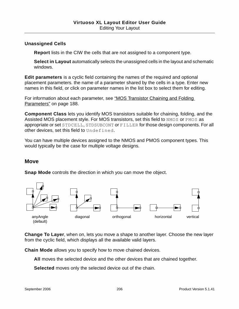
Virtuoso XL Layout Editor User GuideEditing Your Layout
Unassigned Cells
Report lists in the CIW the cells that are not assigned to a component type.
Select in Layout automatically selects the unassigned cells in the layout and schematicwindows.
Edit parameters is a cyclic field containing the names of the required and optionalplacement parameters. the name of a parameter shared by the cells in a type. Enter newnames in this field, or click on parameter names in the list box to select them for editing.
For information about each parameter, see “MOS Transistor Chaining and FoldingParameters” on page 188.
Component Class lets you identify MOS transistors suitable for chaining, folding, and theAssisted MOS placement style. For MOS transistors, set this field to NMOS or PMOS asappropriate or set STDCELL, STDSUBCONT or FILLER for those design components. For allother devices, set this field to Undefined.
You can have multiple devices assigned to the NMOS and PMOS component types. Thiswould typically be the case for multiple voltage designs.
Move
Snap Mode controls the direction in which you can move the object.
Change To Layer, when on, lets you move a shape to another layer. Choose the new layerfrom the cyclic field, which displays all the available valid layers.
Chain Mode allows you to specify how to move chained devices.
All moves the selected device and the other devices that are chained together.
Selected moves only the selected device out of the chain.
anyAngle (default)
diagonal orthogonal horizontal vertical
September 2006 206 Product Version 5.1.41

Virtuoso XL Layout Editor User GuideEditing Your Layout
Selected Plus Left moves the selected device and all of the other devices to the left ofthe chain.
Selected Plus Right moves the selected device and all of the other devices to the rightof the chain.
Delta X/Y allows you to specify the distance to move the selected objects in the X and/or Ydirection.
Apply XY invokes the distance specified in the Delta X/Y fields.
Display Draglines controls whether draglines are displayed during the Move command. Bydefault, the draglines indicate connections from the pins of the object you are moving to pinsof the nearest objects.
For information on how to change the display of draglines, see the Draglines optionsdescribed in “Layout XL Options” on page 65.
Constraint Assisted Control allows objects to be moved only in ways that satisfy theconstraints entered using the constraint manager.
together moves preselected objects in the layout as a group.
individually moves preselected objects in the layout individually.
ignore specifies that constraints have no effect on objects in the layout when they aremoved.
Rotate rotates the component 90 degrees counterclockwise.
Sideways mirrors the component on the y axis (flips it horizontally).
Upside Down mirrors the component on the x axis (flips it vertically).
Set Transistor Folding
Transistor Name displays the name of the first transistor you selected.
Transistor width as specified in the schematic displays the value of the width propertyof the transistor in the schematic.
Number of Fingers lets you enter the number of fingers (divisions) into which you want tofold the transistor. Entering a value in the Number of Fingers field causes the appearanceof the Set Finger Widths option button.
September 2006 207 Product Version 5.1.41

Virtuoso XL Layout Editor User GuideEditing Your Layout
Set Finger Widths, when turned on, changes the Set Transistor Folding form to include newfields that let you enter the width of each finger.
Chain Fingers, when active, allows the software to abut the fingers into chains.
Total Width displays the total value of the all widths you enter in the Width fields.
Add Finger adds another Width field to the form to let you enter the width of an additionalfinger.
Same Width sets all the values in the Width fields to the same width (totaling the same valueas specified in the schematic, unless you override that value in the entries you make in theWidth fields).
Width lets you enter a separate width for each finger.
Delete removes the Width field and decreases the number in the Number of Fingers fieldby 1.
Show Incomplete Nets
Cellview displays the library, cell, and view name of the layout window on which the ShowIncomplete Nets form is focused.
Class displays class names in the list boxes and prepares the search fields for class names.Classes are created in the Constraint Manager form.
Net displays net names in the list boxes and prepares the search fields for net names.
Color choice cyclic field:
Cycle assigns the next entry layer in the color choice cyclic field to the next flight line youchoose.
Note: You can assign one of the y1 through y9 entry layers as a single color for allthe flight lines. You cannot assign the y0 layer as a single color for all flight linesbecause it is the default layer.
As Is keeps the colors currently assigned from the y1–y9 entry layers in the color choicecyclic field.
Set Color sets the color of all incomplete nets highlighted in the Incomplete list box andhighlighted in the layout window to the drawing layer color shown in the color choice cyclicfield.
September 2006 208 Product Version 5.1.41

Virtuoso XL Layout Editor User GuideEditing Your Layout
Search lets you type one or more net or net class names (separated by a space) to behighlighted in the Incomplete or Complete list boxes and in the layout window. You cannotuse the wildcard character ( * ) in this field, but typing the initial characters of net nameshighlights all names in both lists beginning with the specified characters.
Incomplete
The type-in field lets you type partial or complete names of nets to be highlighted in theIncomplete list box and displayed in the layout window (as long as they are incomplete) whenyou click Apply.
The list box lets you select the names of nets you want to display or to which you want toassign a color. You can use Control-click to select more than one or to deselect selectednet names.
Select All displays flight lines for all incomplete nets in the design when you click Apply.
Select from Display lets you click on pins and instances in the layout window to selectthem and displays them when you click Apply.
Less truncates the form so that it does not display the Complete nets list box or theZoom features; the button label changes to More.
More expands the truncated version of the form to include the Complete nets list boxand the Zoom features; the button label changes to Less.
Complete
The type-in field lets you type in partial or complete names of nets to be highlighted in theComplete list box and displayed in the layout window (only if they become incomplete) whenyou click Apply. This capability lets you mark nets of critical importance so that they show upif their connectivity is lost.
The list box lets you select the names of nets you want to display or to which you want toassign a color. You can use Control-click to select more than one or to deselect selectednet names.
Clear All Selections removes the display of flight lines for all incomplete nets in thedesign when you click Apply.
Zoom enlarges the flight lines and the area around them.
All Displayed Flight Lines enlarges as much of an area as possible around all the flightlines.
September 2006 209 Product Version 5.1.41

Virtuoso XL Layout Editor User GuideEditing Your Layout
Individual Flight Line Segments enlarges as much of an area as possible aroundindividual flight lines. This option displays the zoom arrows.
Zoom arrows (--> and <--) display each net individually in the order listed in the Displayfield.
To zoom out again after viewing individual flight line segments, in the Zoom section, selectAll Displayed Flight Lines, then in the Incomplete section, click Select All, and then clickZoom.
The list box at the bottom of the form tells how many incomplete nets are in the design andhow many incomplete nets are displayed.
Stretch
Snap Mode controls the direction in which you can move the object.
Lock Angles, when on, prevents you from changing the angle of a corner or edge as youstretch it.
Delta X/Y allows you to specify the distance to stretch the selected objects in the X and/or Ydirection.
Apply XY invokes the distance specified in the Delta X/Y fields.
Display Draglines controls whether draglines are displayed during the Stretch command.By default, the draglines indicate connections from the pins of the object you are moving topins of the nearest objects.
For information on how to change the display of draglines, see the Draglines optionsdescribed in “Layout XL Options” on page 65.
Use “ignore” for Stretchable Pcells reminds you to choose the ignore option in theConstraint Assisted Control section when you are working with stretchable pcells because, ifConstraint Assisted Controls are active, you cannot use the stretch handle to stretch pcells.
anyAngle (default)
diagonal orthogonal horizontal vertical
September 2006 210 Product Version 5.1.41

Virtuoso XL Layout Editor User GuideEditing Your Layout
Constraint Assisted Control allows objects to be moved only in ways that satisfy theconstraints entered using the constraint manager.
together moves preselected objects in the layout as a group.
individually moves preselected objects in the layout individually.
ignore specifies that constraints have no effect on objects in the layout when they aremoved.
Alignment Form
Selection Mode allows you to align components that are preselected or postselected.
Set reference to align preselected objects works on the preselected set ofcomponents in the design.
Set reference and select objects to be aligned allows you to set the options on theAlignment form and then selects the components to be aligned.
Alignment Direction defines the alignment direction.
horizontal aligns objects in the X direction.
vertical aligns objects in the Y direction.
Align Using indicates how objects are aligned as per the Selection Mode. For preselectedobjects you can use the following options.
Component BBox aligns the Reference Point of the component’s bounding box
Component Origin aligns the origin of the component.
Layer BBox aligns the Reference Point of the specified Layer.
For Post selection use the following available options. Notice that the Reference Pointoptions do not pertain to post selection.
Component Center aligns the centers of components.
Component Edge aligns the left, right, top, or bottom edges of the component.
Component Origin aligns the origins of the objects.
Layer Center determines the bounding box of all of the shapes on the current layer andtakes the center of that bounding box as the reference point. Abutted devices are treatedas a single component when determining the layer center.
September 2006 211 Product Version 5.1.41
Virtuoso XL Layout Editor User GuideEditing Your Layout
Layer Edge determines the bounding box of all of the shapes on the current layer andthen uses either the left, right, top, or bottom edge (depending on which edge is closestto the point you clicked) of the bounding box as the reference point. Abutted devices aretreated as a single component when determining the layer edge.
Layer is a cyclic field showing the layers defined in your technology file. Use this field tospecify the layer to use for aligning by layer edge, center, or BBox.
Reference Point is used with preselection mode options Component BBox and LayerBBox. Specify upperLeft, centerLeft, lowerLeft, upperCenter, centerCenter,lowerCenter, upperRight, centerRight, or lowerRight.
Apply Spacings specifies the spacing between the aligned components.
None does not put any space between the components. This option can cause errors inyour design.
Component Pitch is used only in preselect mode. The distance (in user units) forcenter to center spacing between aligned shapes. You can set this value to a negativenumber to overlap instance.
Component Space specifies the distance (in user units) to maintain between alignedshapes. Set this value to a negative number to overlap instances (and abut themautomatically if Auto Abutment is switched on in the Layout XL Options form).
Pitches is the value when using the Component Pitch option.
Spacing is the value when using the Component Space command.
Sort Components By allows you to change how the selected objects are sorted inrelationship to the reference object. This option only works with preselected objects.
Align Direction Order sorts the objects by the alignment direction order.
Horizontal Order sorts the objects aligned horizontally.
Vertical Order sorts the objects aligned vertically.
Order Selected sorts the objects in the order that they were selected.
Instance Name sorts the objects aligned by instance name.
Net Name sorts the objects aligned by net name.
Reverse Sort allows you to reverse the sorted objects.
Set New Reference specifies the reference for the selected components to be aligned to.
September 2006 212 Product Version 5.1.41

Virtuoso XL Layout Editor User Guide
8Using the Placer
This chapter shows you how to use the placer to automatically place transistors, devices, andcells in both block and cell designs.
This chapter discusses the following topics.
■ Setting Up Virtuoso XL for Placement on page 217
■ Placement Constraints on page 221
■ Placement Parameters and Component Types on page 227
■ Pin Placement on page 230
■ Partitioning the Design on page 237
■ Setting Placement Planning on page 241
■ Running the Placer on page 265
■ Showing Congestions on page 270
For information on Virtuoso XL placer forms, see “Online Forms” on page 271.
The placer is a generic placer that can be used for a variety of placement styles. You controlplacement using topological and geometric constraints.
You begin placement by generating layout connectivity and circuit components with theVirtuoso® XL Layout Editor (Virtuoso XL) layout generation commands. The connectivitysource can be either a Virtuoso schematic composer design or a CDL netlist.
Main Features
■ Re-entrant automated batch placement capability within the Virtuoso environment
■ Connectivity- and constraint-driven placement to achieve overall shortest wiring length
■ Automatic support for a wide variety of placement styles
September 2006 213 Product Version 5.1.41

Virtuoso XL Layout Editor User GuideUsing the Placer
❑ Row-based MOS
❑ Row-based standard cell
❑ Area-based analog
❑ Any combination of the above placement styles concurrently
■ Manual capabilities to partition placement
■ Accelerated engineering change orders
■ Support for the following placement constraints
❑ Distance
❑ Alignment
❑ Grouping
❑ Symmetry
❑ Fixed
■ Automatic row generation for both device-level MOS and standard cells designs
■ Automated pin placement positioning user interface, with support for
❑ Assigning pins to any edge of placement boundary
❑ Ordered and unordered pins
❑ Specifying fixed pin positions
❑ Placing groups of pins at any given spacing
❑ Multiple pins of the same net
Place Menu Command Summary
The Place menu contains these commands.
■ Pin Placement, which opens the Pin Placement form.
Use this command to specify pin location constraints. This command can also be usedto preplace pins independently from the placer.
■ Partitioning, which opens the Partitioning form.
September 2006 214 Product Version 5.1.41
Virtuoso XL Layout Editor User GuideUsing the Placer
Use this command to cluster components together. Partitions are used in PlacementPlanning.
■ Placement Planning, which opens the Placement Planning form.
Use this command to create/modify/edit rows.
■ Placer, which opens the Auto Placer form.
Use this command to run the automatic placer.
■ Show Congestions and Hide Congestions, which toggle the display of congestedareas on the layout. For more information, see “Showing Congestions” on page 270.
■ Rules – Open Rules, which opens the Open Place & Route Rules form.
Use this command to open the placement rules from an ASCII file or the technology file.
■ Rules – New Rules, which opens the New Place & Route Rules form.
Use this command to create new placement rules.
Other Commands Used with the Placer
■ Design – Component Types, which opens the Edit ComponentTypes form
Use this command to update your library with information to guide the placement ofcomponents in rows, and to define parameters for MOS device chaining and folding.
Placement Styles
For row-based MOS transistor-level placement:
■ Diffusion sharing is optimized through both automatic and interactive (with the Pick fromSchematic command) transistor chaining during layout generation. Maximizing diffusionsharing minimizes the diffusion gaps in the generated layout
For standard cell placement:
■ You can place custom and standard cells in single or multiple rows. Rows can be eitherhorizontal or vertical.
September 2006 215 Product Version 5.1.41

Virtuoso XL Layout Editor User GuideUsing the Placer
Figure 8-1 Custom Cells Aligned to Top, with Same Rail Pitch but Different Heights
There are two modes of row definition: user-defined (manual) and component-assisted.
■ In user-defined mode, you define the geometry of a series of rows and specify how toalign and orient components in the rows.
■ In component-assisted mode, the application defines row geometries for you based onarea utilization goals and other design goals you specify. This allows the user to adjustvarious aspects of the design to explore different scenarios.
Note: Row-based is the most structured of all the placement styles. You define specificcomponent types to only be placed with these rows. The devices are constrained within therow to certain orientations and alignments.
Area-based is the least restrictive of the placement styles. Area placement does not requirecomponent types or other constraints. The placer places devices within the placementboundary and reduces the overall wire length between the devices. At the same time,individual constraints that have been placed upon the devices are honored.
With area-based placements the placer also has the freedom to place devices anywherewithin the placement boundary unless devices have been locked down outside of theplacement boundary. Without individual constraints on devices or groups of devices, theplacer’s only objective is to reduce overall wire length and to achieve a balanced placement.Devices will tend to spread out using all the area allowed for placement.
The placement task for row-based designs typically involves these steps. For moreinformation, see “Setting Placement Planning” on page 241.
1. Create component types to use in assigning devices to rows.
2. For MOS device-level designs, set the parameters for device chaining and folding.
For more information, see “MOS Transistor Chaining and Folding Parameters” onpage 188.
Row Shape
September 2006 216 Product Version 5.1.41

Virtuoso XL Layout Editor User GuideUsing the Placer
3. (Optional) Generate layout data from the schematic for critical components using thePick from Schematic command. Make a preliminary placement of the criticalcomponents using the object editing commands. If critical components are hand-placedin their final positions, they can be locked in place during automatic placement topreserve the preplacement.
4. Generate layout and a preliminary placement for the remainder of the design using GenFrom Source if you did not perform Step 3; otherwise use Update Components andNets.
5. Define rows for placement.
You can use component assisted mode only, a combination of assisted and user-defined,or just user-defined.
6. Assign component types to the appropriate rows.
7. Align objects to their respective rows.
Part of defining rows is to check that the component type, alignment, and orientation areset properly.
8. Specify the orientation of components with rows.
9. (Optional) Set confinement, grouping, and other constraints.
10. Place and constrain pins using the Place – Pin Placement command.
11. Run the automatic placer with the Place – Placer command to generate a placement.
12. (Optional) Update constraints and run Place – Placer again.
13. Repeat Step 12 as needed to further refine the placement.
Setting Up Virtuoso XL for Placement
This section describes some variables you might want to set and some design style decisionsyou should make before you begin working with the placer.
Identifying the Placement Translation Rules
The placer and the Virtuoso custom router both use a rules file to define how data should betranslated between the Cadence® Design Framework II (DFII) environment and theplacement and routing environment. In general, the router requires more elaborate translationrules than the placer because the router needs to know more about the design and use ofrouting resources). Rules you create for the router should work unmodified with the placer.
September 2006 217 Product Version 5.1.41

Virtuoso XL Layout Editor User GuideUsing the Placer
Tip
Cadence recommends that you have a separate translation rules file for placementpurposes to minimize the amount of data to be translated. Additional data that is notrequired by the placer will adversely affect the placer’s performance, especially withmixed design styles.
Note: For CMOS device-level designs, diffusion layers must be translated as routing layersin order for the placer to chain devices.
Placement translation rules can be stored in the technology file or in a separate ASCII file.
Setting Cadence Design Framework II Environment Variables
To permit the placer to properly handle permutable pins, type the following in a shell window.
setenv CDS_Netlisting_Mode Analog
or
setenv CDS_Netlisting_Mode Compatibility
Note: Do not set the netlisting mode to Compatibility if you intend to use chaining andfolding for your devices.
If you do not have permutable pins in your design, and make no other use of CDF data, youcan get faster netlisting performance by typing the following.
setenv CDS_Netlisting_Mode Digital
Important
Several placement environment variables have equivalent variables to control theVirtuoso custom router. Placer variables always override their router equivalentsduring placement.
rulesFile
The name of the rules file. If you do not set this variable, thetranslator uses the rules in the technology file. If the rules arenot present in the technology file a warning message appearsindicating that you will have to provide a rules file.
September 2006 218 Product Version 5.1.41

Virtuoso XL Layout Editor User GuideUsing the Placer
Setting MOS Chaining and Folding Parameters
You must set the following .cdsenv parameters to control MOS device folding and chaining.
■ lxDeltaWidth
■ lxWidthTolerance
■ lxAllowPseudoParallelNets
■ lxStackPartitionParameters
Defining the Boundary Layer (Placement Region)
The boundary shape defines the placement region. You specify the name of the boundarylayer-purpose pair at several points in the placement and routing design flow. It is importantthat you identify this layer-purpose pair consistently.
You identify the boundary layer in the boundary translation rules for the Virtuoso customrouter, and you create the boundary shape either with the layout generation commands or bydrawing a shape. When you draw the boundary layer shape, or when you define it duringlayout generation, be sure to use the same layer-purpose pair that you specified in thetranslation rules.
Important
If the iccLayers are not defined in the technology file you will receive the followingerror messages in the Placement Status window:
*ERROR* No boundary layers defined in placer rules, placement cannot continue.
The boundary layer shape must be a single rectangle or polygon. If the boundary layerconsists of more than one shape, or a nonorthogonal shape, the translator exports theenclosing bounding box as the boundary.
Note: The default layer-purpose pair in the translation Rules Editor isprBoundary drawing. The default layer-purpose pair during Virtuoso XL layout generationis also prBoundary drawing.
Abutting Standard Cells
Standard cells are typically defined with a component class type of STDCELL. Duringautomatic placement, standard cells are treated somewhat differently than regular devices.Because of this, there are up-front design considerations for proper standard cell abutment.
September 2006 219 Product Version 5.1.41

Virtuoso XL Layout Editor User GuideUsing the Placer
To achieve optimal placements quickly, standard cells are considered to be correct byconstruction. That is, all standard cells are designed to be abutted without creating designrule errors between each standard cell. The placer does not spend countless cycles ondesign rule checking between internal objects of one standard cell to another, just betweenthe boundaries of adjacent standard cells. Using this method, the placer can use theboundary of each cell as the abutment edge for standard cells.
Note: Full design rule checking does occur between STDCELL component classes and allother devices.
The placer determines the cell boundary for each standard cell by the following precedence:
1. The list of layer-purpose pairs defined in the vcpCellBoundaryLPPs environmentvariable.
2. The (prboundary drawing) layer-purpose pair.
3. The (prboundary boundary) layer-purpose pair.
4. The (instance drawing) layer-purpose pair.
If none of the above layer-purpose pairs exists in the cell, a boundary is derived equal in sizeto all of the objects within the cell. Due to the nature of standard cell design and the desire toshare/overlap objects between adjacent standard cells, defining a boundary is the preferredmethod to ensure proper cell abutment.
Using Automatic Abutment During Placement
If switched on in Virtuoso XL, automatic abutment is performed during layout generation forassisted MOS. To use automatic abutment,
■ Your components (including your MOS device parameterized cells) need to be set upcorrectly with abutment properties.
For an example of such a parameterized cell, see the spcnmos and spcpmos devices inthe sample parameterized cells library. For more information, see the SampleParameterized Cells Installation and Reference.
■ Automatic abutment needs to be switched on in the Layout XL Options form
For more information, see “Setting Up Cells for Abutment” on page 73.
September 2006 220 Product Version 5.1.41

Virtuoso XL Layout Editor User GuideUsing the Placer
Placement Constraints
You can create geometric constraints using the constraint manager or the constraint managerSKILL functions to constrain devices or pins. You can also create constraints through the PinPlacement form to constrain pins.
■ Geometric Constraints
Geometric constraints are used to control the placement of objects. There are varioustypes of geometric constraints that can be created through the constraint manager.
❑ For information about the types of constraints and how they are supported byVirtuoso XL and the placer, see “Constraint Manager Geometric Constraints” onpage 221.
❑ For information about setting constraints through the constraint manager, see theVirtuoso Constraint Manager User Guide.
❑ For information about setting constraints using the constraint manager SKILLfunctions, refer to the Custom Layout SKILL Functions Reference.
■ Pin Placement Constraints
Creating pin constraints through the Pin Placement form lets you place different types ofconstraints on multiple pins at one time and automatically moves the pins to theirassigned locations. Conversely, when creating pin constraints through the constraintmanager, different types of pin constraints must be created separately and placement isnot automatic.
For more information about pin constraints, see “Pin Placement Constraints” onpage 226.
Some of the procedures in this chapter suggest that you set certain types of constraints atcertain points in the design flow, but generally this is not a strict requirement. You canconstrain any device in the layout at any time, except while the placer is running. For example,you can use the placer iteratively, setting increasingly strict constraints as you refine theplacement.
Constraint Manager Geometric Constraints
You can create the following constraints in the constraint manager for placement of objects
■ Distance
■ Alignment
September 2006 221 Product Version 5.1.41
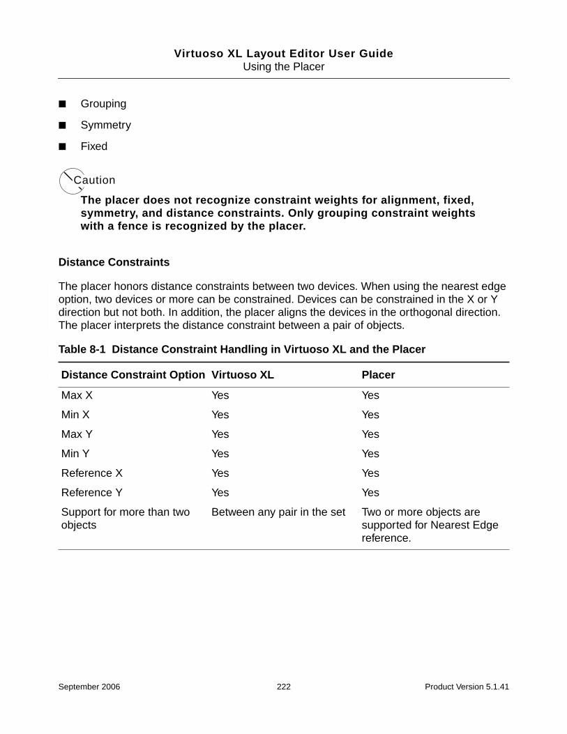
Virtuoso XL Layout Editor User GuideUsing the Placer
■ Grouping
■ Symmetry
■ Fixed
Caution
The placer does not recognize constraint weights for alignment, fixed,symmetry, and distance constraints. Only grouping constraint weightswith a fence is recognized by the placer.
Distance Constraints
The placer honors distance constraints between two devices. When using the nearest edgeoption, two devices or more can be constrained. Devices can be constrained in the X or Ydirection but not both. In addition, the placer aligns the devices in the orthogonal direction.The placer interprets the distance constraint between a pair of objects.
Table 8-1 Distance Constraint Handling in Virtuoso XL and the Placer
Distance Constraint Option Virtuoso XL Placer
Max X Yes Yes
Min X Yes Yes
Max Y Yes Yes
Min Y Yes Yes
Reference X Yes Yes
Reference Y Yes Yes
Support for more than twoobjects
Between any pair in the set Two or more objects aresupported for Nearest Edgereference.
September 2006 222 Product Version 5.1.41

Virtuoso XL Layout Editor User GuideUsing the Placer
Alignment Constraints
The placer supports all alignment references on any layer or the instance bounding box. Thefirst object is the alignment reference object and the rest of the objects are aligned to thatreference. Relative orientation is also supported.
Grouping Constraints
A grouping constraint restricts a group of components to a rectilinear region (“fence”). A fencecan optionally exclude all other, or specified, components.
The placer moves instances as necessary to implement confinement constraints even if theyare not properly positioned in the preplaced view.
Note: A grouping constraint with a fence that has a weight of 255 is translated as a hardfence. Any other weight between 1 and 254 is translated as a soft fence.
Table 8-2 Alignment Constraint Handling in Virtuoso XL and the Placer for Two or MoreObjects
Alignment ConstraintOption Virtuoso XL Placer
Relative Orientation Yes Yes
Align Yes Yes
Reference Layer or BoundingBox
Yes Yes
Ordering No Yes
Table 8-3 Grouping Constraint Handling in Virtuoso XL and the Placer
Grouping ConstraintOption Virtuoso XL Placer
Preserve Relative Position Yes Yes
Fence Yes Yes
Exclude Yes Yes
September 2006 223 Product Version 5.1.41
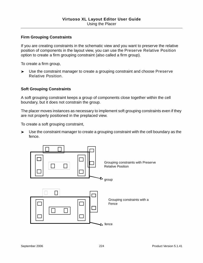
Virtuoso XL Layout Editor User GuideUsing the Placer
Firm Grouping Constraints
If you are creating constraints in the schematic view and you want to preserve the relativeposition of components in the layout view, you can use the Preserve Relative Positionoption to create a firm grouping constraint (also called a firm group).
To create a firm group,
➤ Use the constraint manager to create a grouping constraint and choose PreserveRelative Position.
Soft Grouping Constraints
A soft grouping constraint keeps a group of components close together within the cellboundary, but it does not constrain the group.
The placer moves instances as necessary to implement soft grouping constraints even if theyare not properly positioned in the preplaced view.
To create a soft grouping constraint,
➤ Use the constraint manager to create a grouping constraint with the cell boundary as thefence.
Grouping constraints with PreserveRelative Position
group
Grouping constraints with aFence
fence
September 2006 224 Product Version 5.1.41

Virtuoso XL Layout Editor User GuideUsing the Placer
Symmetry Constraints
The placer implies an order between the pairs involved in the constraint. For example, if Q1and Q2 are constrained along their horizontal line, then the constraint implies that Q1 is belowthe line and Q2 is above.
The placer has the ability of defining a line of symmetry, self-symmetries, and for a given pair(pairwise symmetries). The symmetry axis can be floating as well as fixed.
Fixed Constraints
You can define a fixed constraint with an allowable set of orientations on one or more namedcomponents to a required x and y location. The User Movable option in the Create FixedConstraint form can affect the description of pin position constraints. Components can also
Table 8-4 Symmetry Constraint Handling in Virtuoso XL and the Placer
Symmetry ConstraintOption Virtuoso XL Placer
Floating line No Yes
Fixed line Yes Yes
Horizontal/vertical direction Yes Yes
Note: The placer interprets asymmetry constraint on a pairof objects such that the firstobject must be placed belowa horizontal line of symmetryor to the left of a vertical lineof symmetry. The other objectwould be placed on theopposite side of the line ofsymmetry.
Self-symmetry Only on fixed axis Yes, bounding box center
September 2006 225 Product Version 5.1.41

Virtuoso XL Layout Editor User GuideUsing the Placer
be temporarily locked to a fixed location and orientation through the Edit – Other – LockSelected command.
Pin Placement Constraints
There are three methods of setting constraints on pins. You can use the Pin Placement form,the constraint manager, or the constraint manager SKILL functions.
Pin Constraints Created Using the Pin Placement Form
When creating constraints through the Pin Placement form, three categories of constraintsare used:
■ Alignment
■ Distance
■ Fixed
You can assign pins to a fixed location or to a particular edge and optionally ordered alongeach edge according to your specification. You can also specify fixed spacing for a group ofpins ordered and aligned to an edge.
The Pin Placement form lets you apply all three types of constraints; distance, alignment andfixed on multiple pins at the same time. Once the Apply button is pressed, the pins areautomatically moved to the constraint position.
For information about the Pin Placement form, see “Pin Placement” on page 230.
Table 8-5 Fixed Constraint Handling in Virtuoso XL and the Placer
Fixed Constraint Option Virtuoso XL Placer
X Yes Yes
Y Yes Yes
Orientation Yes Yes
Reference Yes Yes
Edit-Other-Lock Selected Yes Yes
September 2006 226 Product Version 5.1.41

Virtuoso XL Layout Editor User GuideUsing the Placer
Pin Constraints Created in the Constraint Manager
The placer honors distance, alignment, grouping, symmetry, and fixed pin constraints createdthrough the constraint manager or constraint manager SKILL functions. For information aboutthese types of constraints and how they are supported by Virtuoso XL and the placer, see“Constraint Manager Geometric Constraints” on page 221.
When more than one type of constraint is required, each constraint must be createdseparately. For example, if you want to constrain pins to an edge of a bounding box with aspecified pitch, an alignment and a distance constraint must be created. Pins constrainedthrough the constraint manager are moved to their assigned positions in the layout view whenthe placer is run.
Important
Using mixed methods to create constraints is not recommended. To avoid problemsresulting in conflicting and redundant constraints, the creation of pin constraints maybe performed in either of two ways:
❑ Use the Pin Placement form exclusively
or
❑ Use the constraint manager and constraint manager SKILL functions exclusively
For information about setting constraints using the constraint manager or the constraintmanager SKILL functions, see the Virtuoso Constraint Manager User Guide or theCustom Layout SKILL Functions Reference.
Constraint Limitations
■ The placer does not support Virtuoso constraint manager net-based constraints.
■ Constraints must be entered at the top level schematic or layout.
■ The constraint manager and the Pin Placement form, if used at the same time, cancreate conflicting constraints.
Placement Parameters and Component Types
You control how components are assigned to rows, and their chaining and folding parameters,by defining component types.
September 2006 227 Product Version 5.1.41
Virtuoso XL Layout Editor User GuideUsing the Placer
You set the component type using the Design – Component Types command. For moreinformation, see “Component Types” on page 188 and “Defining a Component Type” onpage 190.
Caution
If you edit component types created in IC 4.4.6, using an editor in IC 5.0.0or later, the data is saved a in a new format that is incompatible with IC4.4.6.
There are two reasons you need to define component types.
■ To identify PMOS and NMOS devices to enable chaining and folding
■ To identify groups of devices for row-based placements
Important
You must assign component types for devices that are to be placed within rows.Currently there is no need to define component types for devices that are placed byarea.
Component types are part of the library, cell, or reference library information for cells in whichcomponents are placed. You can define component types at the library level, if all cells in thelibrary share the same types, or you can define component types for the individual cells thatwill contain the placed components. This lets you define a set of types common to all designsin a library and override these for a selected set of designs.
Devices are placed within the place and route boundary regardless of their component typeunless
■ The devices have been locked in place
■ The Place Selected Objects Only option is specified in the Auto Placer form
Important
If the placer does not place a component in the rows, verify that thelxComponentType parameter has been assigned to the component and that therow definition allows for that particular component type to be placed.
September 2006 228 Product Version 5.1.41
Virtuoso XL Layout Editor User GuideUsing the Placer
MOS Transistor Chaining and Folding Parameters
MOS transistors that are candidates for chaining and folding need to have thelxComponentType parameter set with certain values. To set the lxComponentTypeparameter, use the Edit Component Types form.
For more information, see “MOS Transistor Chaining and Folding Parameters” on page 188.
Defining Standard Cell Substrate Contacts
A standard cell substrate contact is neither a contact nor a via; it is a standard cell with acomponent type of STDSUBCONT and two properties defined - lxVcpSubContMaxSpacingand lxVcpSubContMinSpacing - which define the maximum and minimum separationbetween two adjacent standard cell substrate contacts.
To define and place a standard cell substrate contact,
1. Copy a filler cell to use as the basis for the standard cell substrate contact.
2. Add substrate and well contacts in the cell. Whether these are oaVia, via instance, orpolygons is immaterial.
3. Add the lxVcpSubContMaxSpacing and lxVcpSubContMinSpacing properties tothe cell.
a. From the CIW, choose Tools – CDF – Edit.
The Edit Component CDF form is displayed.
b. Specify the library and cell names and click Apply.
The form is populated with the options you can set.
c. In the Component Parameters section, click Add.
The Add CDF Parameter form is displayed.
d. Add the properties and accept the changes.
4. In the Edit Component Types form, define the cell as STDSUBCONT.
5. Run the placer with the Insert Standard Cell Substrate Contacts option switched on.
The placer fills any gaps between placed cells with the specified standard cell substratecontacts.
September 2006 229 Product Version 5.1.41

Virtuoso XL Layout Editor User GuideUsing the Placer
Pin Placement
Use the Place – Pin Placement command to
■ Place pins in fixed positions on the boundary. For more information, see “Placing a Pinon a Boundary Edge” on page 231 and “Placing Ordered Pins on a Boundary Edge” onpage 232.
■ Place pins in fixed position that are not on the boundary. For more information, see“Placing a Pin in a Fixed Position not on the Boundary” on page 233.
■ Place pins directly on lower-level instance terminals on the same layer. For moreinformation, see “Placing a Pin on a Lower-level Instance Terminal” on page 233.
■ Place pin groups with any given pin pitch spacing. For more information, see “AssigningSpacing Between Pins” on page 234.
■ Create vertical and horizontal rails. For more information, see “Converting a Pin into aRail” on page 234.
■ Load the pin constraints from a template file. For more information, see “Loading aTemplate File” on page 236.
■ Report pins and their assigned locations; expand and collapse iterated bus pins (Q<7:0>= Q<7>, Q<6>, Q<5>, and so on.); and handle multiple pins on the same net, gnd.1gnd.2 gnd.3.
You can use the Place – Pin Placement command only if there is a place and routeboundary present in the layout view. To generate a boundary, use the Design – Gen FromSource command.
The Pin Placement form lists all of the pins currently in the design.When you click Apply, allof the pins – other than those that have been confined to a fence – are moved to the specifiedlocations. Pins that are not assigned to an edge or a specific location are placed anywhereon the place and route boundary. When you click Defaults, all of the pins are returned to theirunplaced positions below the design boundary.
Important
Using both the Pin Placement form and the Virtuoso Constraint Manager toconstrain pins can result in conflicting and redundant constraints. Create pinconstraints using either the Pin Placement form or the Constraint Manager and itsassociated SKILL functions.
September 2006 230 Product Version 5.1.41

Virtuoso XL Layout Editor User GuideUsing the Placer
Placing a Pin on a Boundary Edge
To place a pin in a fixed position on the boundary,
1. From the layout window menu bar, choose Place – Pin Placement.
The Pin Placement form is displayed.
2. Choose Unplaced from the Display cyclic field and select the pin from the Pin Namelist box.
You can expand iterated bus pins (for example, A<7:0>) using the Expand button. Thisexpands the bus into individual pins, which you can place individually with differingconstraints.
September 2006 231 Product Version 5.1.41

Virtuoso XL Layout Editor User GuideUsing the Placer
Tip
If you click Link to Layout and select the pin you require in the layout window, thepin name is highlighted automatically in the list box.
3. Do one of the following.
❑ From the Edge cyclic field, choose either Left, Top, Right, Bottom, Any, or As is.
Note: If the boundary is a polygon, the edges are listed as Edge 0, Edge 1, Edge2, and so on. The As is setting leaves the edge settings of pins intact whenchanging other pin properties.
❑ Click Select edge from layout and select the edge you want in the layout window.The Edge cyclic field displays the name of the edge you selected.
4. Choose Fix after Placing from the Location cyclic field.
Fix after Placing places the pin at a location on the boundary and then fixes the pin atthat location, meaning that it cannot be moved during placement. (This option changesto Fix at Placed Location if the selected pin is placed.)
Pins that are User-movable after Placing (User-movable at Placed Location forplaced pins) can be moved by the user to another location; pins that are Floating can bemoved by the placer to another location before being fixed. The As is option specifiesthat the status of the pin is not to be changed after placing.
5. Click Apply.
The pin is aligned to the specified boundary edge in the layout. The Location cyclic fieldchanges to show the coordinates of the center of the pin.
6. Repeat steps 3 through 5 for each pin you want to place on the boundary.
Placing Ordered Pins on a Boundary Edge
To place a group of pins in a specific order along a boundary edge,
1. From the layout window menu bar, choose Place – Move.
The Pin Placement form is displayed.
2. Select one or more pins from the Pin Name list box.
3. Choose the edge you want from the Edge cyclic field.
4. Type a number in the Order field.
September 2006 232 Product Version 5.1.41

Virtuoso XL Layout Editor User GuideUsing the Placer
You can change the order of the pins by selecting a pin in the list and clicking Move pins.Use the Swap order option to swap the position of two selected pins.
5. Click Apply to apply each pin assignment.
The pins are aligned to the specified boundary edge in the layout in the order youspecified.
Placing a Pin in a Fixed Position not on the Boundary
To place a pin in a fixed location not aligned with the boundary,
1. From the layout window menu bar, choose Edit – Move.
2. In the layout window, select an unplaced pin and move it to the required location.
3. From the layout window menu bar, choose Place – Pin Placement.
The Pin Placement form is displayed.
4. Select the pin from the Pin Name list box.
5. Choose Fix after Placing from the Location cyclic field.
6. Click Apply.
The pin is fixed at its current location and is not aligned with any edge.
Note: You can optionally assign the pin to an edge prior to step 5. If you do this, the pin isfixed to the location but the pin’s width and design rules are projected to the specified edge.This projection leaves open a channel on the aligned edge for the fixed pin to facilitate betterrouting from outside the boundary.
Placing a Pin on a Lower-level Instance Terminal
To place a pin directly onto its corresponding instance terminal at a level below in thehierarchy,
1. From the layout window menu bar, choose Place – Pin Placement.
The Pin Placement form is displayed.
2. Select the pin from the Pin Name list box.
3. Choose None from the Edge cyclic field.
4. Choose Floating from the Location cyclic field.
September 2006 233 Product Version 5.1.41

Virtuoso XL Layout Editor User GuideUsing the Placer
5. Click Apply.
The pin you selected is placed over its corresponding instance terminal in the layoutwindow.
Assigning Spacing Between Pins
To set the exact distance between two or more ordered pins or between the pins of a bus pin,
1. From the layout window menu bar, choose Place – Pin Placement.
The Pin Placement form is displayed.
2. Filter the list of pin names as required using the Display cyclic field.
3. Select the pins from the Pin Name list box.
4. Type the center-to-center spacing for the pins in the Pitch field.
Note: You can set a Pitch value only for ordered pins. The Pitch field becomes activeonly when you select a set of ordered and placed pins in the list box, or you select a setof unplaced pins and enter a value in the Order field.
5. Press the Tab key to activate the Apply button.
The pitch is valid if the pins are on the same boundary edge.
6. Click Apply.
The pins move to the positions specified.
Notes
■ Pitch values are enforced only between adjacent pins on an edge, even if the spacing isset between two non-adjacent pins.
■ If you specify a spacing between a pin and an iterated pin, the software applies thespacing between the last pin of the iterated pin and the individual pin.
■ If the specified pitch cannot be satisfied, you see a warning in the CIW and the pins arenot moved.
Converting a Pin into a Rail
To convert a pin into a rail,
September 2006 234 Product Version 5.1.41

Virtuoso XL Layout Editor User GuideUsing the Placer
1. From the layout window menu bar, choose Place – Pin Placement.
The Pin Placement form is displayed.
2. Choose Unplaced from the Display cyclic field.
3. Select a pin from the Pin Name list box.
4. Choose an edge from the Edge cyclic field.
5. Click Apply.
The pin is placed on the boundary.
6. Select the pin in the layout do one of the following.
❑ Click HRail to convert it into a horizontal rail.
❑ Click VRail to convert it into a vertical rail.
When a pin is changed into a rail, it becomes aligned with two edges of the boundary.For a horizontal rail, the alignment is to the left and right edges. For a vertical rail, thealignment is to the bottom and top edges. The rail stretches with the boundary in aconstrained editing mode.
Important
The Pin Placement form does not distinguish layer information when the pins areplaced on the boundary edges. For example, you cannot convert a metal2 pin to arail if that pin occupies the same location as a metal1 pin.
7. (Optional) To view the alignment constraints of the rail,
a. From the CIW choose Tools – Constraint Manager.
b. Change the Select Entity to Geometric Constraints.
c. Click Alignment. The pin placement is displayed. The pin constraints created fromthe Pin Placement form can be viewed but not edited from the Constraint Managerform.
Converting a Rail into a Pin
To convert a rail back into a pin,
1. From the layout window menu bar, choose Place – Pin Placement.
The Pin Placement form is displayed.
September 2006 235 Product Version 5.1.41
Virtuoso XL Layout Editor User GuideUsing the Placer
2. In the layout window, select the rail you want to change.
3. In the Pin Placement form, click unHRail or unVRail as required.
The rail is converted back into a pin and returned to its original size and edge, regardlessof the railing direction.
Loading a Template File
To load information from a template file into the Pin Placement form,
1. From the layout window menu bar, choose Place – Pin Placement.
The Pin Placement form is displayed.
2. Click Template file.
The Load Template File form is displayed.
3. In the left list box, click on the directories to descend into your file hierarchy until youreach the name of the template file to use.
The left and right arrows at the right side of the form let you go up and down in the filehierarchy.
4. In the right list box, click on the name of the template file. The name is entered in theName field.
5. In the Load sections area, turn on the sections of the template file you want to load(I/O Pins).
6. In the Existing data area, do one of the following.
❑ To merge the information from the template with the placement data already invirtual memory, turn on Merge.
❑ To replace the placement data in virtual memory with different placement data in atemplate file, turn on Replace.
7. Click OK.
Saving Pin Placement to a Template File
To save the pin location and constraint information to a template file, use the Design – SaveTo Template command.
Note: Template files from the 4.4.6 release are loaded correctly into the 5.1.41 release.
September 2006 236 Product Version 5.1.41

Virtuoso XL Layout Editor User GuideUsing the Placer
You can save the following information from the pin placement form.
■ Pin location
❑ Floating
❑ Fixed at placed location
❑ As Is
■ Constraints
❑ The boundary edge on which a pin is placed
❑ The order in which a pin has been placed on an edge boundary
❑ If the pin is fixed to a certain location
❑ The required distance between a pin and its neighboring pins
❑ Pins that are either vertical or horizontal rails
Partitioning the Design
To plan the layout more efficiently, cluster components together and assign them to specificareas of the layout. Such areas are called partitions, and they let you monitor the placementmore closely.
Use the Place – Partitioning command to assign components to a partition. A partitiondefines an area in the design to which you can confine components.
■ All placements have to be made inside the design boundary
■ The design boundary is the default partition:
❑ If no partition exists, all the components belong to the design boundary
❑ If a component is not assigned to any partition, it belongs to the design boundary
❑ If no partition is selected, the design boundary becomes the target partition
❑ The keyword “boundary” is a reserved name that cannot be used as a partitionname
■ A component should not be placed in a partition to which it is not assigned
■ A partition can be created without having a shape giving you the ability to partition anetlist or schematic
September 2006 237 Product Version 5.1.41

Virtuoso XL Layout Editor User GuideUsing the Placer
■ Partitions can be made in terms of the connectivity source name space or the layoutname space
■ All members of a one-to-many, many-to-one, or many-to-many group must be assignedto the same partition.
Important
To view engineering changes in the Partitioning form, you must close and re-openthe Partitioning form.
Creating a Partition
1. Create a shape to be attached to the partition.
2. In the Layer Selection Window, choose Edit – Set Valid Layers and add the softFencedrawing layer-purpose pair to the list of valid layers.
3. From the layout window, choose Create – Rectangle and draw a rectangle on thesoftFence layer around the devices that you want to keep together during placement.
4. Choose Place – Partitioning.
September 2006 238 Product Version 5.1.41
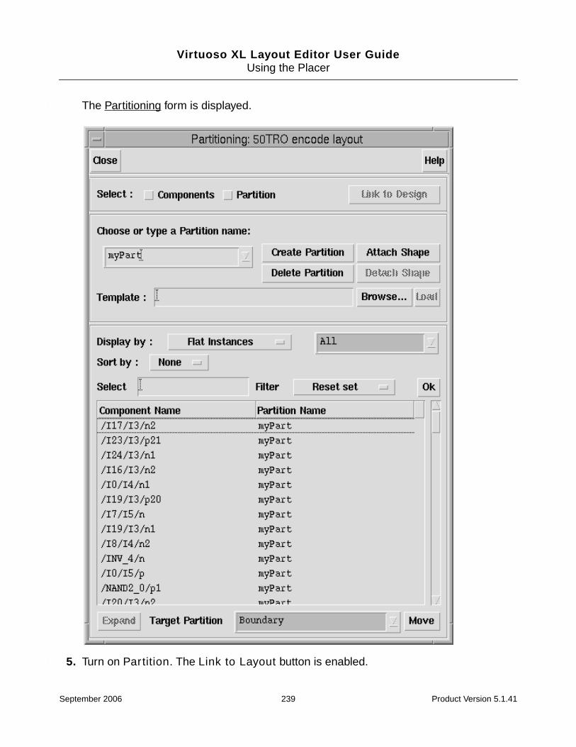
Virtuoso XL Layout Editor User GuideUsing the Placer
The Partitioning form is displayed.
5. Turn on Partition. The Link to Layout button is enabled.
September 2006 239 Product Version 5.1.41
Virtuoso XL Layout Editor User GuideUsing the Placer
6. Click Link to Layout.
7. Click anywhere in the layout cellview to link the Partitioning form to the layout.
In the CIW, a message appears telling you that the Partitioning Form is linked to thedesign.
8. To choose a new partition name, in the Choose or type a Partition name field, do oneof the following:
❑ Type the name of the partition you want to create.
❑ Select an existing partition name from the drop-down list.
9. Click Create Partition.
The new partition name with a question mark appears in the cyclic field. The questionmark denotes that the partition does not have a shape attached to it.
10. Click Attach Shape and click to select the softFence rectangle.
The rectangle is added to the partition.
11. In the Target Partition field, type the new partition name.
12. In the Component Name list, choose the devices to be added to the partition.
13. Click Move.
The devices move into the partition. Notice that the components and the partition arehighlighted.
Loading Information from a Template File
1. Click on the Browse button.
The Open File form is displayed.
2. Do one of the following:
a. If you know the name of the template file, type the name in the Template text field.
b. Click on the directories in the left list box to descend into your file hierarchy until youreach the name of the template file to use. Click on the name of the template file inthe right list box to enter it in the Name field.
The left and right arrows at the right side of the form let you go up and down in thefile hierarchy.
September 2006 240 Product Version 5.1.41

Virtuoso XL Layout Editor User GuideUsing the Placer
3. Click OK.
Saving Partitions to a Template File
You can save the partition information from the cellview to a template file using the Design –Save To Template command. Below is an example of the partition information that is savedto the template file.
partition_section(connectivity "VCPLIB DFF schematic"(partition partition1(shape rectangle ((5.300000 3.050000) (13.500000 10.600000)))(cell /P4)(cell /P6)(cell /P7)(cell /P2)(cell /P12))
Setting Placement Planning
Placement planning lets you define where in the layout you want to place transistors and otherdesign elements.
Before you can set the placement planning, you or the library developer must first define thecomponent types for placement. Components that have types assigned to rows can only beplaced in these rows. For more information, see “Defining a Component Type” on page 190.
There are two row definition modes for the Placement Planning form: Assisted and User-Defined.
■ The assisted mode automates typical styles of MOS and standard cell placement
■ The user-defined mode offers greater flexibility but less automation and supports bothtransistor- and cell-level placement
You set the mode in the Style field at the top of the Placement Planning form.
Assisted CMOS Placement
The Assisted CMOS row definition style helps you define rows that fit your area budget. Youcan change the independent design variables that constrain the row shapes and observetheir effect on area utilization and folded transistor widths.
September 2006 241 Product Version 5.1.41

Virtuoso XL Layout Editor User GuideUsing the Placer
Limitations of Assisted CMOS Placement
The Assisted CMOS placement style restricts the placement to the most typicalarrangements. There are several limitations that are not present in the user-defined rowdefinition mode.
■ All rows must be horizontal or vertical
■ All rows have the same width and span the entire placement region
Note: Row width can vary if the region is polygonal.
■ Each row contains either NMOS or PMOS devices but not both and not any othercomponent types
■ The number of NMOS and PMOS rows is the same
■ There is a regular arrangement of alternating N and P rows that follows one of thesepatterns:
❑ N-P
❑ P-N
❑ N-P-P-N
❑ P-N-N-P
■ All rows have the same device alignment relative to the devices in adjacent rows: inside,outside, or center
■ Device rotation depends on the row and pattern
■ The rows can extend outside of the boundary/partition
Note: The placer can place only within the boundary/partition
If any of these limitations is not acceptable, you can either
■ Define the rows in the user-defined mode
■ Define the rows as completely as possible using the component-assisted mode and thenrefine the definitions in the user-defined mode
■ Use assisted mode on either standard cell or MOS, but not both at the same time.
September 2006 242 Product Version 5.1.41

Virtuoso XL Layout Editor User GuideUsing the Placer
About Calculated Values
For both NMOS and PMOS transistors, the system calculates the number of transistors andthe minimum, maximum, and average transistor widths. To update the displayed values afteraltering variables, click Calculate Estimates.
The system also calculates the normalized percentage of intra-row and inter-row areautilization for the placement region. A value of 100% in the Intra Row field means that theentire width of the placement region is used by the devices. If there are too many devices tofit within the placement region, rows may overlap or extend outside the placement region. Inthis case, one or both of the Region Utilized values might be greater than 100%.
Planning Placement with the Assisted CMOS Style
To use the Assisted CMOS row definition style,
1. Choose Place – Placement Planning.
September 2006 243 Product Version 5.1.41
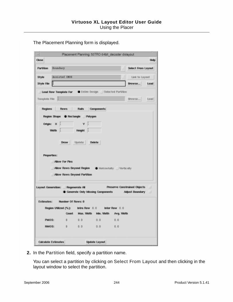
Virtuoso XL Layout Editor User GuideUsing the Placer
The Placement Planning form is displayed.
2. In the Partition field, specify a partition name.
You can select a partition by clicking on Select From Layout and then clicking in thelayout window to select the partition.
September 2006 244 Product Version 5.1.41

Virtuoso XL Layout Editor User GuideUsing the Placer
3. Change the Style to Assisted CMOS.
4. Use the controls in the Regions tab to create a placement region within the partition.
The placement region should be contained within the partition. For example, you mightrestrict assisted placement to the lower part of the partition, leaving the upper partavailable for manual placement. Or, you might leave space around the periphery forrouting.
❑ Type the dimensions of the drawing region in the Width and Height fields.
❑ Type the X and Y coordinates of the location where you want the row in the Originfields.
You can see the X and Y coordinates of the cursor position in the status line at thetop of the layout window. If you do not type any coordinates, the new row is placedat the lower left corner of the design boundary.
❑ Specify the placement region manually in the layout window, select Draw and youare prompted to point at the first corner of the region’s rectangle.
September 2006 245 Product Version 5.1.41

Virtuoso XL Layout Editor User GuideUsing the Placer
Important
When targeting a partition for assisted row generation, the estimator uses the entirepartition area in its calculation.You can optionally specify a region within the partitionby using the Draw option. If a region is defined the estimator will use the region areainstead of the partition area.
5. Click the Rows tab to update the row properties.
Note: If rows are already defined, change the Style to Manual User-Defined and therow information is displayed at the bottom of the Placement Planning form. Click on therow that you want to edit. The row properties are updated in the Row Name field.
6. Set the direction of the rows.
For more information on the other fields in the Rows section, see Placement Planningon page 280.
September 2006 246 Product Version 5.1.41

Virtuoso XL Layout Editor User GuideUsing the Placer
7. Click the Rails tab to define the rails.
❑ Choose a Layer and type values in the Width and Net fields for power and ground.
The layers are valid layers that are not used as vias or contacts.
❑ In the Rail To Device Spacing field, specify the minimum distance between thepower rail and PMOS and NMOS devices.
❑ In the Pattern cyclic field, choose a pattern for the alternating NMOS and PMOSrows.
❑ In the Position cyclic field, choose the position of the rail relative to the row (Inside,Outside, or Center).
Caution
Do not add a u at the end of a value for rail width and spacing rulesbecause the value will be converted to 0.000001. For example, 12u isconverted to 0.012.
To create non-rectangular regions,
1. Choose Place – Partitioning and create a partition for the components.
2. Choose Place – Placement Planning.
3. In the Style cyclic field, choose Assisted CMOS.
4. From the Partition cyclic field, choose a partition name.
September 2006 247 Product Version 5.1.41

Virtuoso XL Layout Editor User GuideUsing the Placer
5. In the Regions tab, click Draw and you are prompted to draw a region. Create the regioninside of the partition.
6. Click Calculate Estimates.
The rows are created and the row statistics are displayed at the bottom of the PlacementPlanning form.
7. Draw another separate region that does not overlap the previous region (area nowcontains rows) using the Draw option.
8. Click Calculate Estimates.
The rows are created and the row statistics are displayed at the bottom of the PlacementPlanning form.
Note: The final utilization must be calculated by hand using the row statistics from bothregions.
9. Click the Components tab.
September 2006 248 Product Version 5.1.41

Virtuoso XL Layout Editor User GuideUsing the Placer
Caution
Do not add a u at the end of a value for spacing rules because the valuewill be converted to 0.000001. For example, 12u is converted to 0.012.
10. From the Align Components cyclic field, choose Inside, Outside, or Center.
Note: Alignment can be either top, bottom, or center for horizontal rows or right, left, orcenter for vertical rows.
11. In the Width Threshold field, type the minimum width and in the Diffusion Spacingfield, type the required diffusion spacing for the PMOS and NMOS transistors within therow.
12. To place only the devices for the selected component below the prBoundary, clickRegenerate All.
The Update Layout option at the bottom of the Placement Planning form updates thecurrent layout with the components and deletes existing components. This option is usedon a selective basis based on the selected partition and style.
N-row
P-row
P-row
N-row
P-row
N-row
Inside (NPPN pattern)
P-row
N-row
Outside (NP pattern)
P-row
N-row
Center
September 2006 249 Product Version 5.1.41
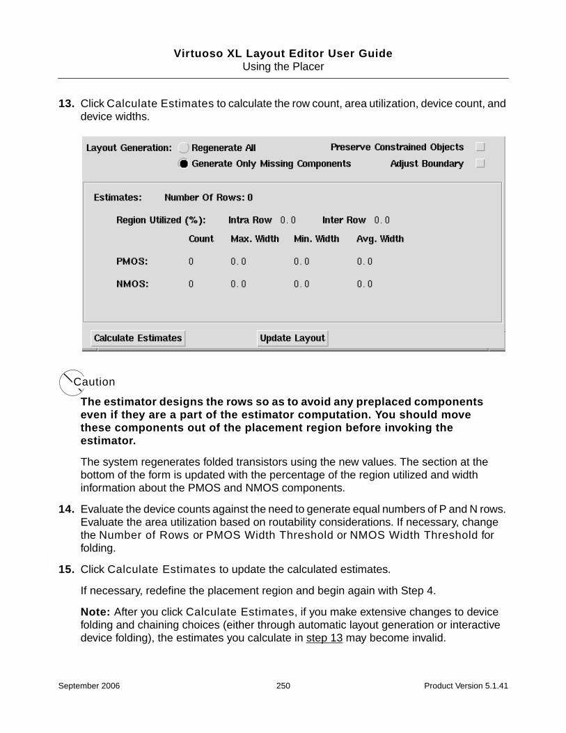
Virtuoso XL Layout Editor User GuideUsing the Placer
13. Click Calculate Estimates to calculate the row count, area utilization, device count, anddevice widths.
Caution
The estimator designs the rows so as to avoid any preplaced componentseven if they are a part of the estimator computation. You should movethese components out of the placement region before invoking theestimator.
The system regenerates folded transistors using the new values. The section at thebottom of the form is updated with the percentage of the region utilized and widthinformation about the PMOS and NMOS components.
14. Evaluate the device counts against the need to generate equal numbers of P and N rows.Evaluate the area utilization based on routability considerations. If necessary, changethe Number of Rows or PMOS Width Threshold or NMOS Width Threshold forfolding.
15. Click Calculate Estimates to update the calculated estimates.
If necessary, redefine the placement region and begin again with Step 4.
Note: After you click Calculate Estimates, if you make extensive changes to devicefolding and chaining choices (either through automatic layout generation or interactivedevice folding), the estimates you calculate in step 13 may become invalid.
September 2006 250 Product Version 5.1.41

Virtuoso XL Layout Editor User GuideUsing the Placer
Using Assisted Standard Cell Mode
To use the Assisted Standard Cell row definition mode
1. Select Place – Placement Planning.
The Placement Planning form is displayed.
2. Change the Style to Assisted Standard-Cell.
3. Click the Regions tab.
4. Do one of the following.
a. Type the dimensions of the row(s) in the Width and Height fields and the X and Ycoordinates of the location where you want the row in the Origin field.
You can see the X and Y coordinates of the cursor position in the status line at thetop of the layout window. If you do not type in any coordinates, the new row is placedat the lower left corner of the design boundary.
b. To draw the placement region manually in the layout window, click Draw.
The layout window prompts you to point at the first corner of the region’s rectangle.
September 2006 251 Product Version 5.1.41

Virtuoso XL Layout Editor User GuideUsing the Placer
5. Click the Rows tab.
6. In the Row Name field, type the names of the rows to be designed and set the directionof the rows.
7. Switch on Use Filler Cells to insert filler cells between the other cells in the row. Choosethe cells by doing one of the following.
❑ Type names into the text field to select filler cells you defined in the Edit ComponentTypes form.
September 2006 252 Product Version 5.1.41

Virtuoso XL Layout Editor User GuideUsing the Placer
❑ Click Choose Types and choose the names of the filler cells from the list thatappears in the Choose Component Types form. Use the Search field to filter theselection.
You must also specify a type when using the Use Substrate Contacts option. UseSTDSUBCONT as the Component Class.
8. Click the Rails tab.
❑ Choose a Layer and type values in the Width and Net fields for power and ground.
The layers are valid layers that are not used as vias or contacts.
September 2006 253 Product Version 5.1.41

Virtuoso XL Layout Editor User GuideUsing the Placer
❑ In the Pattern cyclic field, choose a pattern for the alternating power and groundrails.
❑ In the Rail to Rail Spacing field, type a value for the spacing between power andground rails for the same row.
9. Click Calculate Estimates to calculate the row count, area utilization, device count, anddevice widths.
The section at the bottom of the form is updated with the percentage of the regionutilized.
If you choose to use the Regenerate All option all standard cells are regenerated oncethe Update Layout option is invoked. Or you can use the Generate Only MissingComponents option and the missing components are created. Generation/regenerationonly affects standard cells within the chosen partition.
Note: To modify the size of a rail, change the Rail information and then click CalculateEstimates.
PG
Vdd
Gnd
GP
Gnd
Vdd
PGGP rails not shared
GPPG shared rails
GP
PG
GND
Vdd
Gnd
September 2006 254 Product Version 5.1.41

Virtuoso XL Layout Editor User GuideUsing the Placer
10. Evaluate the device counts against the need to generate equal numbers of PG to GProws. Evaluate the area utilization based on routability considerations. If necessary,change the Width or Height fields or the Width Threshold for folding. Click CalculateEstimates to update the calculated estimates.
Note: After you click Calculate Estimates, if you make any changes to row definitions(either through automatic layout generation or interactive device folding), the estimatesyou calculate in step 10 are rendered invalid.
11. Click Apply to save your row definitions.
Manual User-Defined Row-Based Placement
The Manual User-Defined mode for row definition lets you define row boundaries flexibly.For example, you can draw rectangles to delimit individual rows. Use the manual mode forplacements above the device level or for MOS device placement styles that are notaccommodated in Assisted MOS mode.
The picture below shows an example of a placement region with four rows. Rows 1 and 2, thelower rows, span only half the placement region. Rows 3 and 4 span the entire placementregion.
Figure 8-2 Examples of Rows
Defining Rows Manually
To define rows or columns manually,
1. From the layout window, choose Place – Placement Planning.
Region
1
2
3
4
September 2006 255 Product Version 5.1.41

Virtuoso XL Layout Editor User GuideUsing the Placer
The Placement Planning form is displayed.
2. Change the Style to Manual User-Defined.
3. Click General to define one or more rows.
a. Type the name of the rows to be designed in the Row Name field.
b. Set the direction of the rows.
c. Type the X and Y coordinates of the location where you want the first row in theOrigin field.
You can see the X and Y coordinates of the cursor position in the status line at thetop of the layout window. If you do not type in any coordinates, the new row is placedat the lower left corner of the design boundary.
d. Type the dimensions of the rows in the Width and Height fields.
e. Click Draw and draw the shadow of the row. The row is not created until you pressthe Create New button.
f. In the Spacing Between Rows field, type the spacing you want between rows.
g. Type in the number of rows you want in the Number of Rows to Create field.
If Number of Rows to Create is greater than 1, then this will create an array ofrows with the same devices and attributes at a fixed spacing between adjacent rows.
4. Click the Types tab.
a. Click Edit. The Choose Component Types form is displayed.
b. Select the component type and click OK. The selected component type appears inthe Component Type(s) field.
c. Specify a Component Grid, Reference Point For Type, Reference Point ForRow, Offset, and Allowed Orientations.
d. Click Create New and the component type is displayed in the Types field box.
e. To change any of the component types properties select the component type in theTypes field and change the properties on the form. Click Update and thecomponent type properties are updated.
5. In the Rails section of the form,
September 2006 256 Product Version 5.1.41

Virtuoso XL Layout Editor User GuideUsing the Placer
a. Specify the Layer, Width, and Net name of the rail.
b. Change the Reference Point for Rail and Reference Point For Row to beBottom, Top, or Center as needed.
c. Specify a Rail Offset from Row.
d. Click Add. The rail is added and displayed in the Rails field.
e. To change any of the rail properties, select the rail in the Rails field and change theproperties on the form. Click Update to update the rail with the new properties.
Defining User-Programmed Styles
The Style File text field on the Placement Planning form lets you specify a SKILL file that cancorrespond to one or more styles.
The style definition should contain the following information;
■ The style name.
■ The required fields in the form.
You are allowed to program the style-specific parameter and statistics sections from theform. Other than label fields, the name of the field is used as the common reference forthe field value. A hash table is passed to the callbacks with the extracted values. Fieldnames should be unique to the form.
■ Names of files that contain style-specific callbacks.
Creating the Style File
The file structure of a style-definition consists of a header and contents. The header is asfollows
(lxPlcStyleHeader(version versionValue)(creator "name or tool")(timeLastChanged "YYYY:MM:DD HH:MM:SS")...)
The function lxPlcStyleHeadermust be the first item in the file aside from comments. Theversion indicates if the style can be loaded. If the version is too old or too new, you mustupdate the file or use a different file. The creator and timeLastChanged fields are forreporting purposes only.
September 2006 257 Product Version 5.1.41

Virtuoso XL Layout Editor User GuideUsing the Placer
The style definition function is as follows;
(lxPlcDefineStyle(name "nameString")(paramGUICreationCB "functionName")(statGUICreationCB "functionName")(estimatorCB "functionName")(updateLayoutCB "functionName")(loadFile "fileName"...)...)
The function, lxPlcLoadStyle loads the style definition files. This function should verify theversion from the header. If the version is correct the file is loaded. The loadFile functionrefers to one or more files containing the SKILL callbacks that can be loaded using SKILLload.
Note: You can use implicit load to load sections that are common to many styles
Loading the Style File
When you select the Calculate Estimates button, the style file is loaded and then checksfor the selected style along with
■ Identifying the components based on the chosen partition
■ Obtaining the region information from the form
■ Clearing the region from any rows
■ Setting all the necessary parameters
■ The style-specific estimation function returns row specifications
❑ If the estimation function returns any row specifications, these specifications arepassed to a function that generates rows from specifications.
Style File Example
The following is a standard cell example.
;First write a file, mySTDCell.stl, that declares the style as follows,
(lxPlcStyleHeader(version 1.0)(creator "customer A")(timeLastChanged "2001:1:24 13:00:00")
)
(lxPlcDefineStyle(name "mySTDCellStyle")
September 2006 258 Product Version 5.1.41

Virtuoso XL Layout Editor User GuideUsing the Placer
(paramGUICreationCB "mySTDCellParamGUICreationCB")(statGUICreationCB "mySTDCellStatGUICreationCB")(estimatorCB "mySTDCellEstimatorCB")(updateLayoutCB "mySTDCellUpdateLayoutCB")(loadFile "mySTDCellFun.il")
)
When the system loads the mySTDCell.stl file, which will search for the file calledmySTDCellFun.il and load it. The file looks like
(defun mySTDCellParamGUICreationCB (cvId x y other)(let (field1 field2...)(setq field1 (hiCreate???Field...))(setq field2 (hiCreate???Field...))...(list(list(list field1 ?:? ?:? ?) (list field2 ?:? ?:? ?)...)?:?nil))
The program can take the list of fields and add them to the form.
(defun mySTDCellStatGUICreationCB (cvId x y other)(let (field1 field2 ...)(setq field1 (hiCreate???Field...))(setq field2 (hiCreate???Field...))...(list(list(list field1 ?:? ?:? ?)(list field2 ?:? ?:? ?)...)?:?nil))
)
(defun mySTDCellEstimationCB (cvId paramTable); The param table is a table of agreed-upon parameters; and their corresponding values.; gather information about the current partition, and its; contents.; generate/update the layout for the partition in; the scratch cellview.; select the components that correspond to the style.; estimate the space needed for the components.; estimate the rows needed for the components.; return the list of row specifications.
)
September 2006 259 Product Version 5.1.41
Virtuoso XL Layout Editor User GuideUsing the Placer
(defun my STDCellUpdateLayoutCB (cvId paramTable); gather information about the current partition, and its; contents.
; generate/update the layout for the partition in; the current cellview.return t/nil)
Drawing Rows
You can define rows by drawing them one at a time in the layout window. Select Draw anddefine the placement region for assisted MOS or cells.
Redefining a Row
Rows are actual database objects you can move and stretch graphically. To graphically editrows make sure that the row drawing layer-purpose pair is a valid layer and madeselectable in the Layer Selection Window (LSW).
You can delete a row by changing the Style to Manual User-Defined mode. The rows aredisplayed at the bottom of the Placement Planning form. You can select a row and use theDelete Selected option to delete the selected tows, or select the row in the layout windowand then delete it.
Setting Up Power and Ground Rails
You can define arrays of multiple rows in one step to create alternating rows with the samedefinitions. This arrangement facilitates the layout of power lines. Figure 8-3 on page 261shows a portion of a buffer array with alternating NMOS and PMOS transistors in columns.
September 2006 260 Product Version 5.1.41
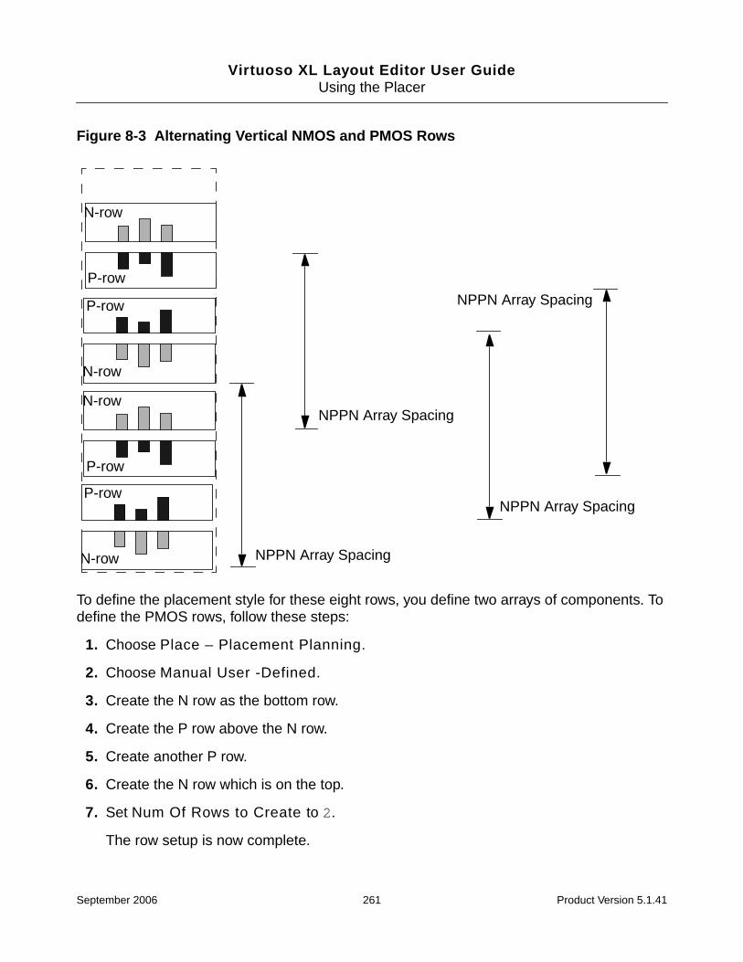
Virtuoso XL Layout Editor User GuideUsing the Placer
Figure 8-3 Alternating Vertical NMOS and PMOS Rows
To define the placement style for these eight rows, you define two arrays of components. Todefine the PMOS rows, follow these steps:
1. Choose Place – Placement Planning.
2. Choose Manual User -Defined.
3. Create the N row as the bottom row.
4. Create the P row above the N row.
5. Create another P row.
6. Create the N row which is on the top.
7. Set Num Of Rows to Create to 2.
The row setup is now complete.
P-row
N-row
P-row
N-row
P-row
N-row
P-row
N-row
NPPN Array Spacing
NPPN Array Spacing
NPPN Array Spacing
NPPN Array Spacing
September 2006 261 Product Version 5.1.41

Virtuoso XL Layout Editor User GuideUsing the Placer
For other arrangements of power lines between rows, you might, for example, need to definearrays of every fourth or eighth row in order to achieve the desired mirroring pattern.
About Horizontal and Vertical Rows
You can define both horizontal and vertical rows for placement. To do this, set the desireddirection as you define each row or set of rows.
Figure 8-4 on page 262 shows how the Width and Height parameters should be set forhorizontal and vertical rows. As this figure illustrates, the Width is measured along thedirection of the rows.
Figure 8-4 Setting Width and Height for Horizontal and Vertical Rows
1. Row direction is Vertical, Width is 10, Height is 4, Spacing is 2.
2. Row direction is Horizontal, Width is 10, Height is 4, Spacing is 2.
About Device Orientation
There is no implied rotation of devices in vertical rows. The Orientation value you specify inthe Placement Planning form is always relative to the master cell coordinates. Figure 8-5 onpage 263 shows the undesired result of placing the same device with orientation R0(unrotated) in both a horizontal and vertical row.
(0,0)(0,0)
1 2
wid
th
height
height
width
September 2006 262 Product Version 5.1.41

Virtuoso XL Layout Editor User GuideUsing the Placer
Figure 8-5 Rotation of Devices in Vertical and Horizontal Rows
About Device Abutment and Orientation
For MOS row placement, diffusion would be abutted along the row direction as shown inFigure 8-6 on page 263
Figure 8-6 MOS Row with Diffusion Abutted Along the Row Direction
The permitted orientations in the example in Figure 8-6 on page 263 would depend on theorientation of the transistor in its master cell. Assuming that the polysilicon shape is verticalin the master cell for the transistor, for a horizontal row the reasonable orientations would beR0 (unrotated), R180 (rotated 180 degrees), MX (mirrored along the x axis) and MY (mirroredalong the y axis). R90 would not be an advisable orientation.
For standard cells, the power and ground rails would run parallel to the row direction, asshown in Figure 8-7 on page 264.
UnrotatedMaster
UnrotatedMasterPermitted Orientations in row: R0, R180, MX, MY
September 2006 263 Product Version 5.1.41

Virtuoso XL Layout Editor User GuideUsing the Placer
Figure 8-7 Standard Cells with Power Rails Parallel to the Row Direction
About Space at the End of a Row and Row Compaction
The placer can abut MOS devices so that rails meet each other. However, when placingstandard or other cells that are not set up for device abutment, the placer does not compactthe rows to ensure that the rails abut.
The placer never extends rails to the row boundary. If the cells do not entirely fill the row, youmay need to extend the rails or use filler cells.
Figure 8-8 on page 264 shows standard cells placed within a row. The cells do not abut eachother and the power rails do not extend to the right side row boundary.
Figure 8-8 Row with Extra Space
Choose Component Types Form
From the Placement Planning form, in Manual User-Defined mode, the Edit button in theTypes section opens the Choose Component Types form. Use this form to identify thecomponent types to place in the currently active rows.
Row Shape
September 2006 264 Product Version 5.1.41

Virtuoso XL Layout Editor User GuideUsing the Placer
Below the Search button is a list of component types in the current design. Use the mouseto highlight the types you wish to include in the Component Types field of the PlacementStyle form, and then click OK.
Search scrolls the list to the component type name you type into the field. The name mustmatch exactly. You can then highlight the name. This field is useful if you have a long list oftypes.
Running the Placer
You launch the Virtuoso custom placer with the Auto Placer form. The placer runs inforeground, background, or Load Balancing Service (LBS) mode, reporting its status in theVirtuoso XL Placement Status window.
Note: While the placer is running on a cellview, the cellview is switched to read-only modeand you cannot perform edits on it but you can edit any other cellview. When the placer hasfinished, the cellview is switched back to edit mode.
After the placer finishes, the placed cellview appears (if you are updating the source view withthe placed view, or if you are creating a new view and chose the Open Window option).
After placement, you can iteratively
■ Lock the position of components whose placement is good.
September 2006 265 Product Version 5.1.41

Virtuoso XL Layout Editor User GuideUsing the Placer
■ Refine the constraints on other components to better guide the placer.
■ Rerun the placer as needed to improve the placement results.
Prerequisites to Placement
To prepare for placement
1. Set any necessary UNIX and DFII environment variables before launching the Cadencesoftware.
For more information on setting variables, see “Setting Up Virtuoso XL for Placement” onpage 217.
2. If you only want to place some of the components, select the components to be placedin the cellview window and turn on Place Selected Objects Only.
Running the Placer: Initial Placement
To start the automatic placer and perform an initial placement of the selected components
1. Choose Place – Placer.
September 2006 266 Product Version 5.1.41

Virtuoso XL Layout Editor User GuideUsing the Placer
The Auto Placer form is displayed.
2. Turn on Global Placement.
3. Set the other placement options on the left side of the form as needed.
For information on these options, see “Auto Placer” on page 272.
4. To save the placed cellview with a different view name,
a. Switch on the Save As option.
b. Fill in the Library, Cell, and View fields. By default the view name is layout.plc.
You can also change the library or cell name, or browse to choose the cellviewname.
Caution
Do not use the view name “placerScratch”. This name is reserved by theplacer.
5. Click OK or Apply.
Note: The layout.plc cellview is placed on top of the layout cellview.
September 2006 267 Product Version 5.1.41
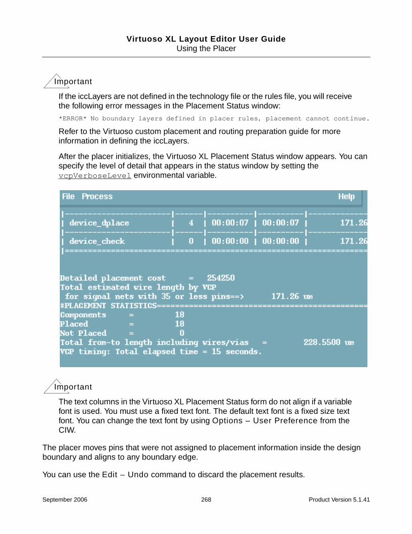
Virtuoso XL Layout Editor User GuideUsing the Placer
Important
If the iccLayers are not defined in the technology file or the rules file, you will receivethe following error messages in the Placement Status window:
*ERROR* No boundary layers defined in placer rules, placement cannot continue.
Refer to the Virtuoso custom placement and routing preparation guide for moreinformation in defining the iccLayers.
After the placer initializes, the Virtuoso XL Placement Status window appears. You canspecify the level of detail that appears in the status window by setting thevcpVerboseLevel environmental variable.
Important
The text columns in the Virtuoso XL Placement Status form do not align if a variablefont is used. You must use a fixed text font. The default text font is a fixed size textfont. You can change the text font by using Options – User Preference from theCIW.
The placer moves pins that were not assigned to placement information inside the designboundary and aligns to any boundary edge.
You can use the Edit – Undo command to discard the placement results.
September 2006 268 Product Version 5.1.41

Virtuoso XL Layout Editor User GuideUsing the Placer
Stopping the Placer
To stop the placer before it has completed all placement passes,
1. Select Place- Placer.
2. Set the options in the Auto Placer form and click OK.
The XL Placement Status form is displayed.
3. In the Virtuoso XL Placement Status form select Process – Stop Placer.
Running Load Balancing Service (LBS)
LBS lets the placer support load sharing capability. The procedure for running LBS is asfollows.
1. Set either the Cadence default LBS queue or an LSF queue.
2. In the latter case, set the LBS_BASE_SYSTEM environmental variable to LBS_LSF.
3. Set the search path to include the path to any load sharing service scripts.
Note: You set the path using the vcpGlobalPathScript environmental variable.
4. Activate the load sharing queue daemons.
5. Disk directories must have been exported to enable load sharing service to work acrossthe network.
6. Password restrictions have been eliminated to enable batch automatic login from onemachine to the other.
Troubleshooting Placement Results
This section discusses common placement problems and some possible solutions.
Problem: Components were placed with overlaps.
Solution: The boundary region or the rows are too small. Redraw the boundary or rows.
Refining Placement Results
To refine the placement results
September 2006 269 Product Version 5.1.41
Virtuoso XL Layout Editor User GuideUsing the Placer
■ Set grouping and fixed constraints by choosing Tools – Constraint Manager in theCIW.
■ Redefine the row boundaries.
■ For MOS transistor-level designs, modify the layout for one or more transistors with theEdit – Transistor Chaining and Transistor Folding commands.
Running the Placer: Detailed Placement
To perform a detailed placement after refining the constraints
1. Choose Place – Placer. The Auto Placer form is displayed.
2. Deselect Global Placement.
3. Choose Optimize Placement.
4. Continue as with initial placement, beginning with step 4.
Showing Congestions
After you have run placement, you can use the Place – Show Congestions command tohighlight areas where design elements are so close together that routing might be a problem.
To show congested areas in your placed design
➤ Choose Place – Show Congestions.
The system surrounds congested areas with tiles on different highlight layers showingdegrees of congestion.
The layer purpose pairs designFlow drawing through designFlow drawing9 are usedto show congestion. Each layer purpose pair represents different regions of routingresource utilization.
For example, the designFlow drawing layer purpose pair represents utilization from 0to 11.111111%. The designFlow drawing1 layer purpose pair represents utilizationfrom 11.111112 to 22.222222%, until layer designFlow drawing8 which representsutilization of 88.888888% to 100%. Layer purpose pair designFlow drawing9represents utilization over 100%.
The legend bar appears displaying the percentage of utilization for each designFlowlayer.
The command name changes to Hide Congestions.
September 2006 270 Product Version 5.1.41

Virtuoso XL Layout Editor User GuideUsing the Placer
To remove the highlighting around congested areas in your placed design
➤ Choose Place – Hide Congestions.
The highlighting surrounding the congested areas disappears.
The command name changes to Show Congestions.
Troubleshooting Placement
Error Messages
Online Forms
■ Auto Placer
■ Partitioning
■ Choose Component Types
■ Pin Placement
■ Load Template File
■ Placement Planning
Message: location: ("lib" "cell" "view")
reason: VCP: half_spacing_violation (componentname)(left_boundary)
Description: Generated by the placer whenever the distance between oneedge of the place and route boundary and the nearestcomponent violates the half-maximum-spacing rule.
The half-maximum-spacing rule is a distance equal to half of allof the spacing rules for the layers specified in the iccLayersection of the rules file.
This happens typically if the place and route boundary’s width,length, or both are smaller than expected.
Troubleshooting: To resolve this violation, turn on either intra or inter compactionwhich will adjust boundary in the appropriate direction.
September 2006 271 Product Version 5.1.41

Virtuoso XL Layout Editor User GuideUsing the Placer
■ Placement Planning (Assisted Standard-Cell)
■ Placement Planning (Assisted Mixed CMOS/Standard-Cell)
■ Placement Planning (Manual User-Defined)
Auto Placer
Group CMOS Pairs is for CMOS designs that have been generated with chaining.
Note: This option does not work with devices that have been manually-abutted becauseclustering needs chaining information.
Preserve Abutment Chains specifies that abutment chains that were generatedautomatically during Gen From Source or Placement Planning are preserved duringplacement. When this option is switched off, such chains are dissolved leaving the placer freeto share diffusion on individual transistors, which can reduce the wire length of polysilicongate connections and result in better alignment.
Important
Cadence recommends that you leave this option switched on and inspect the resultsobtained by the automatic chaining function to see if they are satisfactory. If they arenot, you can switch off the option and let the placer try to generate a better result.
Note: When disabling this option, consider the following:
❑ It is more efficient for the placer to place transistor chains generated by Gen FromSource or during Placement Planning than to place individual transistors. This isespecially true when placing a large number of transistors.
❑ Diffusion sharing during automatic placement is not guaranteed because the placeris geared primarily towards reducing overall wire length. If the area within the rowsis limited, the placer attempts to share diffusion; if there is excess area within therows, it does not.
Group M factor Devices automatically adds a grouping constraint for complimentary MOSdevices that have a multiplication factor from the schematic.
Place Selected Objects Only places only the objects in the selected set. When switchedoff, the placer places all of the objects in the cellview.
Allow Rotation rotates the components as a part of optimization. When switched off, theplacer can move components but not rotate them.
September 2006 272 Product Version 5.1.41

Virtuoso XL Layout Editor User GuideUsing the Placer
ECO Mode places any components that were left unplaced outside the design boundary, butit does not touch the placement of components that are already placed inside the designboundary.
The placer keeps placed components close to their original placed locations and insertsunplaced components into the design. In some cases, in order to minimize wire length, itmight be necessary to move already-placed components; for example, if you want to add abuffer next to each register, but do not want to change the overall relative positions of theplaced components.
If you want to place unfixed components, use the Place Selected Objects Only option orthe Edit – Other – Lock Selected command.
In ECO mode, all filler cells are deleted before the placement and reinserted after placement.
Global Placement places components without regard to any initial placement. The placeroptimizes global objectives such as total wire length and overlap violations betweencomponents might be ignored. You would typically use this option the first time you place adesign or to discard previous unsatisfactory placement results.
Optimize Placement performs a detailed placement. This option lets the placer run until theobjective cost is achieved. The default value is off.
Runtime controls how long the optimizer tries to optimize to achieve the best possibleplacement. Choices are quick, moderate, and optimized.
Run Spacer within Rows adds or removes space within each row.
Run Spacer between Rows adds or removes space between each row.
Note: The boundary is adjustable when you run the spacer option.
Reserve Space For Routing (%) lets you specify the percentage of extra space you wantadded, above what the routing channels between rows should occupy, to improve routability.Use this option with the Run Spacer between Rows.
Adjust Boundary automatically recalculates the boundary when you click Update Layout.
Insert Filler Cells fills empty spaces in the rows with the filler cells you defined in theComponent Types form.
Insert Substrate Contacts inserts standard cell substrate contacts in the rows based on aspecified minimum and maximum contact spacing value. This option is honored only whenusing the Assisted Standard Cell and Assisted Mixed CMOS/Standard Cell placementstyles. For more information on substrate contacts, see “Defining Standard Cell SubstrateContacts” on page 229.
September 2006 273 Product Version 5.1.41

Virtuoso XL Layout Editor User GuideUsing the Placer
Save As lets you specify a new library, cell, and view name for the placed cellview. By default,this option is switched off and the current and placed names are the same and these fieldsare grayed out.
Important
Be sure to save the placed cellview to disk before translation if you want to preserveany edits that are still in memory.
Edits to the output cellview are not saved to disk automatically before placement. To discardthe changes the placer makes, do not save the output cellview. However, this also discardsany edits in memory.
■ When you let the placer update the source layout cellview.
■ When you specify a different cell or view name, but that cellview happens to be open andmodified in another window.
Library sets the new library for the placed cellview.
Cell sets the new cell name for the placed cellview.
View sets the new view name for the placed cellview.
Browse displays a library browser to let you choose the new name.
Open Window displays the placed view in a new window after placement, if it is not alreadydisplayed. Otherwise, the system updates the output view in an existing window.
Rules lets you type the name of a rules file.
Set File opens the Open File window, which displays the files on your system so thatyou can choose a rules file.
Show More Options displays more placement options
Job Host
Foreground runs the placer within the same process as the current session.
Background runs the placer in a child process on the same machine.
LBS submits the placement job to the LBS (Load Balancing Service) whichschedules the placement job according to your settings and the availability ofcomputing resources. The final placement session will run on the selected hostusing the dfII working directory for data read/write.
September 2006 274 Product Version 5.1.41
Virtuoso XL Layout Editor User GuideUsing the Placer
Offset From Boundary lets you control the minimum spacing between the boundaryedge and the nearest component. The default value is half of the maximum of all thespacing rules for the layers specified in iccLayer section of translator rules.
Show Placement Progress displays a graphical representation of the placer’sprogress.
Place Un-Assigned Components In Mixed Mode when switched on allowsunassigned (floating) components to be moved when using the Assisted Mixed CMOS/Standard Cell placement mode. When switched off, unassigned components are notmoved.
Note: Enabling this option can adversely affect the performance of the placer.
Partition lets you place components by partition instead of placing the entire cellview.From the cyclic field, select the partition you want to place.
Only Check Cell Boundary, when switched on, specifies that the placer use the cellboundary to check for out-of-design violations. When switched off, the placer uses thephysical boundary to check out-of-design violations.
Note: The physical boundary is instance boundary including every layer of itsmaster. The cell boundary is the boundary enclosing only active and polysiliconlayers. Enabling this option checks that the outlines of all of the components areinside the boundary, but allows the contents of the components to be outside theboundary.
Partitioning
Select lets you set up the partitioning environment.
Components lets you select a component in the layout window and have thecomponent name highlighted in the Partitioning form.
Partition lets you select a partition in the layout window and have the partition namehighlighted in the Partitioning form. This option must be turned on when you areattaching a shape on a soft fence to an existing partition.
Note: You must click on the Link to Design button and then click inside the layoutwindow to highlight the selected component/partition in the Partitioning form.
Link to Design links the Partitioning form to the cellview in the context of partitioning. Forexample, the Link to Design option lets you select components or partitions in order tohighlight them in the Partitioning form.
September 2006 275 Product Version 5.1.41

Virtuoso XL Layout Editor User GuideUsing the Placer
Choose or type a Partition name adds the name of a new partition or lets you choosefrom a list of existing partition names. If the Partitioning form is linked and any shape isalready attached to the partition, the partition is highlighted in the layout window.
Create Partition adds a new partition with the name in the Choose or type a Partitionname text field.
Delete Partition deletes the partition in the Choose or type a Partition name field.If there are any components assigned to this partition, they are reassigned to theboundary by default.
Attach Shape attaches a shape to the current partition. The shape must already existin the layout and must exist only on the soft fence layer. If the shape is already assignedto another partition, then it is detached from the other partition and attached to thecurrent partition.
Detach Shape detaches the selected shape from the current partition.
Template lets you specify a template file name. Typing a name in the text field enables theload button and the template file is loaded to the form.
Browse lets you browse/specify a template file name using the Open File form.
Load loads the partition information from the template file specified in the Template textfield in to the Partitioning form.
Display by defines what is displayed in the component browser.
Flat Instances displays instances that have no hierarchy.
Hierarchical Instances displays instances at the top level of the hierarchy.
Note: If your design is flat, then the display will appear the same for both FlatInstances and Hierarchical Instances options. This is because the HierarchicalInstances option displays top level instances and Flat Instances displays leafinstances. Top level and leaf instances in a flat design are the same.
Component Types displays the component types used with the instances.
Source master displays the names of all the master symbols that exist in the layout.
Target master displays the names of all the master layouts that exist in the layout.
All displays all partitions and their components.
Boundary displays components that are placed in the boundary.
September 2006 276 Product Version 5.1.41

Virtuoso XL Layout Editor User GuideUsing the Placer
Sort by sorts information by component Name or Partition. The partitions themselves aresorted first, followed by the components in each partition. Click on either the ComponentName or Partition Name table header to sort the table.
Select lets you type in a search pattern to select components in the component browser.
Filter lets you filter the components displayed in the component browser.
Reset set clears the highlighted set.
Add to set lets you add to a new selected set to an already existing set. For examplethe existing highlighted set is aX aY aZ aP aQ. You select b* in the componentbrowser, then select Add to set and click OK. The new highlighted set is all of thecomponents including a* and b*.
Remove from set lets you remove any selected elements from the selected set. Forexample, if you type in the Select field ap and then click Ok the new highlighted set isaX aY aZ aQ.
Limit to set lets you highlight a subset of components from the highlighted set. Forexample if you type in the Select field aY and click OK the new highlighted set is aY.
Ok invokes the action based on correct Filter options.
Expand/Collapse lets you expand (or collapse) a selected hierarchical node in thecomponent browser. If the selected node is not hierarchical, the button is grayed out.
Target Partition is the name of the partition to which the components are to be assigned.
Move assigns the selected instances from the component browser to the current partition.
Choose Component Types
Search scrolls the list to the component type name you type into the field. The name mustmatch exactly. This field is useful if you have a long list of types. To select a device or deviceson which you want to perform an action, click on the device you want to select, or hold downControl and click to select more than one device.
Pin Placement
Display Control specify what pins are displayed in the Pin Placement form.
September 2006 277 Product Version 5.1.41

Virtuoso XL Layout Editor User GuideUsing the Placer
Display lets you specify from a combination of two cyclic fields which pins are displayed.The choices are All, Placed, Unplaced, Left, Top, Right, and Bottom and All, Fixed,User-movable, Ordered, Unordered, I, O, IO pins.
Select edge from layout displays the pins on the selected edge of the boundary.
Sort By name lists the pins in alphabetical order. By order sorts each pin entry peredge, ordered pins, in their order, first and unordered pins after them.For Pitch listsplaced pins in a special manner related to their possible Pitch values with each other.
Link to Layout lets you select pins in the layout window and have them highlighted in thePin Name list box. You can also select pins in the Pin Placement form and they are selectedin the layout. Click Link to Layout and click anywhere in the layout window to link the PinPlacement form to the layout window, then select the pins that you want highlighted in the PinPlacement form.
Unlink from layout unlinks the Pin Placement form from the linked layout window.
Select lets you type in a pin name and press the Tab key to select the pin in the Pin Namelist box. You may use wildcard characters ‘?’ and ‘*’ to select more than one pin. The wildcharacter ‘?’ replaces any single character and ‘*’ replaces any substring of characters,including a single character in the pin names.
Pin Name is the name of the pin.
Edge is the edge of the boundary that the pin is placed on.
Order defines how the pins are ordered.
Pitch the distance between neighboring pins.
Note: Press the Tab key to activate the Apply button.
Status indicates the status of the pin. For example, Fixed tells you that the pin is fixed andM indicates that the pin is fixed but also user-movable in the location that the pin is fixed at.
Type I, O, or IO.
Layer the layer the pin has been created on.
Edit selected pin or select more pins from list lets you edit pin settings includingplacement of them on a boundary edge.
Edge determines the edge that the pin is placed on. The options are Left, Top, Right,Bottom, Any, None, and As is. The As is setting leaves the edge settings of pins intactwhen changing other pin properties.
September 2006 278 Product Version 5.1.41

Virtuoso XL Layout Editor User GuideUsing the Placer
Order specifies the order of the selected pins. to place the pins as unordered pins, enter“-” or a blank space. To specify an order for the pins, enter a digit.
Pitch assigns a specific distance between two or more neighboring pins. The pitch valuemay be set for ordered pins, unordered pins, or a combination of the two.
Location defines the final placed positions of the pins.
❑ Fixed at Placed Location commits the selected pins to their current positions.
❑ User-movable at Placed Location lets you move the pins to a new location. Thisoption is similar to a Fixed constraint, but you may use the Edit – Move commandto move the pin to another location. The pin will automatically be fixed to the newlocation. If you move a fixed pin to a different location, the placer will put the pin backto its original fixed location.
❑ Floating changes previously set fixed pins or user-movable pins to be unfixed ornon-user-movable.
❑ As is option does not constrain pins to a certain location.
Select edge from layout lets you select the edge from the layout canvas. This is best usedfor polygonal boundaries.
Iterated Pins lets you expand or collapse the listing of iterated (bus) pins.
Interleave lets you interleave the bits of any two selected buses.
Expand expands the pin lists to show all bits of one or more iterated pins.
Collapse collapses the pin lists to show bus notation for one or more iterated pins.
All performs the expand or collapse function on all the pins in the list box.
Selected performs the expand or collapse function only on highlighted pins in the listbox.
Change Order lets you change the order of ordered pins.
Arrow to the left/down moves the selected pins down in the list box.
Arrow to the right/up moves the selected pins up in the list box.
Swap inverts the order of two selected pins in the list box.
Place pins as in specifies where the pin placement information comes from.
Schematic view takes a snapshot of the relative position of the pins in the schematicand updates the pin placement in the layout window accordingly.
September 2006 279 Product Version 5.1.41

Virtuoso XL Layout Editor User GuideUsing the Placer
Template file displays the Load Template File form which lets you specify a templatefile containing information to be loaded into the pin placement form. For moreinformation, see Load Template File.
HRail elongates the selected pins from one end of the boundary to another horizontally.
VRail elongates the selected pins from one end of the boundary to another vertically.
Load Template File
Name is the user-defined name of the template file.
Filter lets you specify a letter or keyword to filter the template file names.
Load sections loads the I/O Pins section of the template file.
Existing data either merges or replaces the template file.
Placement Planning
Partition lets you select a partition that was created in the Partitioning form.
Select From Layout lets you select a partition directly from the layout window.
Style lets you select and load one of the available styles. The style you select determines thecontrols that are made available on the Placement Planning form.
The rest of this section describes the options available with the Assisted CMOS style, whichlets you define rows with full flexibility for device or cell-level placement styles.
Style File lets you load a user-defined style if none of the predefined styles matches yourrequirements.
Browse opens the Open File form.
Load loads the file specified in the Style File field.
Load Row Template For activates the buttons and fields for the template file. You can thenchoose whether to load the template file for the Entire Design or the Selected Partitiononly.
Template File is the template file created using the Design – Save To Templatecommand.
Browse opens the Open File form.
September 2006 280 Product Version 5.1.41
Virtuoso XL Layout Editor User GuideUsing the Placer
Load loads the specified template file.
Regions lets you specify a region, which is a boundary within which to apply the parametersspecified in the form. After the rows are created, the regions no longer exist, but you can stillmanipulate the rows. You can draw rows outside the region.
Region Shape determines the shape of the region.
❑ Rectangle creates a rectangular region.
❍ Origin X sets the X coordinate of the lower left corner of the lowest numberedrow (region) being edited.
❍ Origin Y sets the Y coordinate of the lower left corner of the row (region).
❍ Width lets you enter the width of the row you want (larger than the height if youwant horizontal rows).
❍ Height lets you enter the height of the row you want (larger than the width ifyou want vertical rows).
❑ Polygon creates a polygonal region.
❍ Points field appears after selecting the Polygon option. Type in thecoordinates.
Draw lets you use the mouse to draw the shape you want in the layout window. Whencreating a Rectangle, the shape you draw sets the placement region and the X, Y,Width, and Height fields are filled in with the appropriate values. When creating aPolygon, the coordinates of the individual vertices are updated in the Points text field.
Update updates the region.
Delete removes the drawn region.
Properties lets you set properties for the pins.
❑ Allow For Pins secures a space from the boundary edge equal to the size of thepin plus the spacing rule. This prevents rows from overlapping pins.
❑ Allow Rows Beyond Region automatically expands the row beyond the region ifneeded. Specify the direction of expansion to be either horizontal or vertical.
❍ Horizontally draw stretch rows in a horizontal direction.
❍ Vertically draw stretch rows in a vertical direction.
❑ Allow Rows Beyond Partition automatically expands the row beyond thepartition if needed.
September 2006 281 Product Version 5.1.41

Virtuoso XL Layout Editor User GuideUsing the Placer
Rows lets you create rows.
Row Name specifies a name for your rows. If you do not specify a row name, the defaultrow name is assigned, starting with Row1, Row2, and so on.
Direction is the default direction for rows, either Horizontal or Vertical.
Utilization
❑ Utilization Inside Rows specifies how much of a row is used by the componentsand how much is left for routing. Select 100% to specify that all of the row space isavailable for use by components or specify a percentage value in the Specify %field.
❑ % Area Covered By Rows specifies how much of a region is occupied by rowsand how much is left for routing channels. Provide a row Spacing or specify apercentage value in the Specify % field.
Number Of Rows lets you Specify the number of rows to be created or leave it to theplacer to create the Maximum number possible in the space available.
Create Pin Row creates a pin row centered in the design along the y-axis. During theplacement step, all pins that not constrained to the cell boundary are placed in this centerpin row and optimized to minimize wire length. Use this option if you are developingstandard cell libraries, where placing the pins on the boundary is not desired.
Spacing Between N-Row and P-Row controls the distance between the N-P pair.
Minimum N-P Component Spacing specifies the minimum distance between the N-P pair. The default value is the largest of all the minimum spacing values for the currentcellview layers.
Top and Bottom Edge Offset specifies the offset from top or bottom of the region tothe nearest component.
Rails lets you specify information for power and ground pins.
Power
❑ Layer specifies the layer on which the rails are drawn.
❑ Width specifies the width of the rails.
❑ Net specifies the net to which the rails belong.
❑ Rail to Device Spacing specifies the minimum distance between the power railand PMOS and NMOS devices. If you do not specify a value, the software uses thelargest minimum spacing value specified for PMOS/NMOS device layers to powerrail layers.
September 2006 282 Product Version 5.1.41

Virtuoso XL Layout Editor User GuideUsing the Placer
Ground
❑ Layer specifies the layer on which the rails are drawn.
❑ Width specifies the width of the rails.
❑ Net specifies the net to which the rails belong.
❑ Rail to Device Spacing specifies the minimum distance between the ground railand PMOS and NMOS devices. If you do not specify a value, the software uses thelargest minimum spacing value specified for PMOS/NMOS device layers to groundrail layers.
Pattern specifies how N and P devices alternate between rows or how cells alternate.The patterns that you can use are N-P-P-N, P-N-N-P, N-P, or P-N.
Position controls the relative position of rails with regard to rows. Specify either Inside,Outside, or Center.
Components
PMOS
❑ Width Threshold is the maximum width allowed after MOS device folding isperformed. The default value comes from the CDF data for the device. If thethreshold value is 0, the value of the Fold Threshold option set in the EditComponent Types form is used.
❑ Diffusion Spacing sets the minimum spacing required between adjacent MOSchains. This value affects the estimation of the number of rows required.
NMOS
❑ Width Threshold is the maximum width allowed after MOS device folding isperformed. The default value comes from the CDF data for the device.
❑ Diffusion Spacing sets the minimum spacing required between adjacent MOSchains. This value affects the estimation of the number of rows required.
Align Components controls the relative alignment of devices in adjacent rows.
❑ Inside aligns the P and N devices toward each other.
❑ Outside aligns the devices away from each other.
❑ Center aligns the devices with the row center line.
Allow Chaining enables components to be chained.
❑ Stack Partition Parameter sets the device chaining partition parameters.
September 2006 283 Product Version 5.1.41
Virtuoso XL Layout Editor User GuideUsing the Placer
❑ Max Chain Size sets the maximum number of devices in chain.
Layout Generation controls whether components are regenerated if necessary or onlymissing components are added.
Regenerate All regenerates all components.
Generate Only Missing Components generates only missing components.
Preserve Constrained Objects is used with only the Regenerate All option. Theconstrained objects are not deleted.
Adjust Boundary lets the placer estimate and change the boundary size when thelayout is updated.
Estimates creates the rows but does not generate any layout components.
Calculate Estimates gives you an estimate of the PMOS and NMOS devices within a row.
Update Layout updates the current layout with the assumption that you do not want tochange any of the parameters.
Placement Planning (Assisted Standard-Cell)
Partition lets you select a partition that was created in the Partitioning form.
Select From Layout lets you select a partition directly from the layout window.
Style lets you select and load one of the available styles. The style you select determines thecontrols that are made available on the Placement Planning form.
The rest of this section describes the options available with the Assisted Standard-Cellstyle, which lets you define rows with full flexibility for device or cell-level placement styles.
Style File lets you load a user-defined style if none of the predefined styles matches yourrequirements.
Browse opens the Open File form.
Load loads the file specified in the Style File field.
Load Row Template For activates the buttons and fields for the template file. You can thenchoose whether to load the template file for the Entire Design or the Selected Partitiononly.
September 2006 284 Product Version 5.1.41

Virtuoso XL Layout Editor User GuideUsing the Placer
Template File is the template file created using the Design – Save To Templatecommand.
Browse opens the Open File form.
Load loads the specified template file.
Regions lets you specify a region, which is a boundary within which to apply the parametersspecified in the form. After the rows are created, the regions no longer exist, but you can stillmanipulate the rows. You can draw rows outside the region.
Region Shape determines the shape of the region.
❑ Rectangle creates a rectangular region.
❍ Origin X sets the X coordinate of the lower left corner of the lowest numberedrow (region) being edited.
❍ Origin Y sets the Y coordinate of the lower left corner of the row (region).
❍ Width lets you enter the width of the row you want (larger than the height if youwant horizontal rows).
❍ Height lets you enter the height of the row you want (larger than the width ifyou want vertical rows).
❑ Polygon creates a polygonal region.
❍ Points field appears after selecting the Polygon option. Type in thecoordinates.
Draw lets you use the mouse to draw the shape you want in the layout window. Whencreating a Rectangle, the shape you draw sets the placement region and the X, Y,Width, and Height fields are filled in with the appropriate values. When creating aPolygon, the coordinates of the individual vertices are updated in the Points text field.
Update updates the region.
Delete removes the drawn region.
Properties lets you set properties for the pins.
❑ Allow For Pins secures a space from the boundary edge equal to the size of thepin plus the spacing rule. This prevents rows from overlapping pins.
❑ Allow Rows Beyond Region automatically expands the row beyond the region ifneeded. Specify the direction of expansion to be either horizontal or vertical.
❍ Horizontally draw stretch rows in a horizontal direction.
September 2006 285 Product Version 5.1.41
Virtuoso XL Layout Editor User GuideUsing the Placer
❍ Vertically draw stretch rows in a vertical direction.
❑ Allow Rows Beyond Partition automatically expands the row beyond thepartition if needed.
Rows lets you create rows.
Row Name specifies a name for your rows. If you do not specify a row name, the defaultrow name is assigned, starting with Row1, Row2, and so on.
Direction is the default direction for rows, either Horizontal or Vertical.
Utilization
❑ Utilization Inside Rows specifies how much of a row is used by the componentsand how much is left for routing. Select 100% to specify that all of the row space isavailable for use by components or specify a percentage value in the Specify %field.
❑ % Area Covered By Rows specifies how much of a region is occupied by rowsand how much is left for routing channels. Provide a row Spacing or specify apercentage value in the Specify % field.
Number Of Rows lets you Specify the number of rows to be created or leave it to theplacer to create the Maximum number possible in the space available.
Standard Cell Grid is a user-enforced grid. The value should not contradict the standardcell widths. The grid can be a fraction of the greatest common divisor of the standard cellwidths. For example if you have two cells of widths 2.5 and 4.5. The greatest common divisoris 0.5 so you can choose values of 0.01, 0.1, 0.5, and so on.
Use Filler Cells inserts filler cells that have been defined in the Edit Component Types formbetween the standard cells in the row. Type the names of the filler cells into the field, or clickChoose Types and choose the names of the filler cells from the list that appears in theChoose Component Types form.
Use Substrate Contacts inserts standard cell substrate contacts that have been defined inthe Edit Component Types form between the standard cells in the row. Type the names of thestandard cell substrate contacts into the field or click Choose Types and choose the namesof the standard cell substrate contacts from the list that appears in the Choose ComponentTypes form.
Rails lets you specify information for power and ground pins.
Power
❑ Layer specifies the layer on which the rails are drawn.
September 2006 286 Product Version 5.1.41
Virtuoso XL Layout Editor User GuideUsing the Placer
❑ Width specifies the width of the rail.
❑ Net specifies the net to which the rails belong.
Ground
❑ Layer specifies the layer on which the rails are drawn.
❑ Width specifies the width of the rail.
❑ Net specifies the net to which the rails belong.
Pattern specifies how ground and power rails alternate between rows. The patterns thatyou can use are G-P, P-G, G-P-P-G, or P-G-G-P.
Rail To Rail Spacing specifies the spacing between power and ground rails for thesame row.
Layout Generation controls whether components are regenerated if necessary or onlymissing components are added.
Regenerate All regenerates all components.
Generate Only Missing Components generates only missing components.
Preserve Constrained Objects is used with only the Regenerate All option. Theconstrained objects are not deleted.
Adjust Boundary lets the placer estimate and change the boundary size when thelayout is updated.
Estimates creates the rows but does not generate any layout components.
Calculate Estimates gives you an estimate of the PMOS and NMOS devices within a row.
Update Layout updates the current layout with the assumption that you do not want tochange any of the parameters.
Placement Planning (Assisted Mixed CMOS/Standard-Cell)
Partition lets you select a partition that was created in the Partitioning form.
Select From Layout lets you select a partition directly from the layout window.
Style lets you select and load one of the available styles. The style you select determines thecontrols that are made available on the Placement Planning form.
September 2006 287 Product Version 5.1.41
Virtuoso XL Layout Editor User GuideUsing the Placer
The rest of this section describes the options available with the Assisted Mixed CMOS/Standard-Cell style, which lets you define rows with full flexibility for device or cell-levelplacement styles.
Style File lets you load a user-defined style if none of the predefined styles matches yourrequirements.
Browse opens the Open File form.
Load loads the file specified in the Style File field.
Load Row Template For activates the buttons and fields for the template file. You can thenchoose whether to load the template file for the Entire Design or the Selected Partitiononly.
Template File is the template file created using the Design – Save To Templatecommand.
Browse opens the Open File form.
Load loads the specified template file.
Regions lets you specify a region, which is a boundary within which to apply the parametersspecified in the form. After the rows are created, the regions no longer exist, but you can stillmanipulate the rows. You can draw rows outside the region.
Region Shape determines the shape of the region.
❑ Rectangle creates a rectangular region.
❍ Origin X sets the X coordinate of the lower left corner of the lowest numberedrow (region) being edited.
❍ Origin Y sets the Y coordinate of the lower left corner of the row (region).
❍ Width lets you enter the width of the row you want (larger than the height if youwant horizontal rows).
❍ Height lets you enter the height of the row you want (larger than the width ifyou want vertical rows).
❑ Polygon creates a polygonal region.
❍ Points field appears after selecting the Polygon option. Type in thecoordinates.
Draw lets you use the mouse to draw the shape you want in the layout window. Whencreating a Rectangle, the shape you draw sets the placement region and the X, Y,
September 2006 288 Product Version 5.1.41

Virtuoso XL Layout Editor User GuideUsing the Placer
Width, and Height fields are filled in with the appropriate values. When creating aPolygon, the coordinates of the individual vertices are updated in the Points text field.
Update updates the region.
Delete removes the drawn region.
Properties lets you set properties for the pins.
❑ Allow For Pins secures a space from the boundary edge equal to the size of thepin plus the spacing rule. This prevents rows from overlapping pins.
❑ Allow Rows Beyond Region automatically expands the row beyond the region ifneeded. Specify the direction of expansion to be either horizontal or vertical.
❍ Horizontally draw stretch rows in a horizontal direction.
❍ Vertically draw stretch rows in a vertical direction.
❑ Allow Rows Beyond Partition automatically expands the row beyond thepartition if needed.
Rows lets you create rows.
Row Name specifies a name for your rows. If you do not specify a row name, the defaultrow name is assigned, starting with Row1, Row2, and so on.
Direction is the default direction for rows, either Horizontal or Vertical.
Utilization
❑ Utilization Inside Rows specifies how much of a row is used by the componentsand how much is left for routing. Select 100% to specify that all of the row space isavailable for use by components or specify a percentage value in the Specify %field.
❑ % Area Covered By Rows specifies how much of a region is occupied by rowsand how much is left for routing channels. Provide a row Spacing or specify apercentage value in the Specify % field.
Number of Rows lets you Specify the number of rows to be created or leave it to theplacer to create the Maximum number possible in the space available.
Standard Cell Grid is a user-enforced grid. The value should not contradict the standardcell widths. The grid can be a fraction of the greatest common divisor of the standard cellwidths. For example if you have two cells of widths 2.5 and 4.5. The greatest common divisoris 0.5 so you can choose values of 0.01, 0.1, 0.5, and so on.
September 2006 289 Product Version 5.1.41

Virtuoso XL Layout Editor User GuideUsing the Placer
Use Filler Cells inserts filler cells that have been defined in the Edit Component Types formbetween the standard cells in the row. Type the names of the filler cells into the field, or clickChoose Types and choose the names of the filler cells from the list that appears in theChoose Component Types form.
Use Substrate Contacts inserts standard cell substrate contacts that have been defined inthe Edit Component Types form between the standard cells in the row. Type the names of thestandard cell substrate contacts into the field or, click Choose Types and choose the namesof the standard cell substrate contacts from the list that appears in the Choose ComponentTypes form.
Rails lets you specify information for power and ground pins.
Power
❑ Layer specifies the layer on which the rails are drawn.
❑ Width specifies the width of the rail.
❑ Net specifies the net to which the rails belong.
Ground
❑ Layer specifies the layer on which the rails are drawn.
❑ Width specifies the width of the rail.
❑ Net specifies the net to which the rails belong.
Pattern specifies how ground and power rails alternate between rows. The patterns thatyou can use are G-P, P-G, G-P-P-G, or P-G-G-P.
Rail To Rail Spacing specifies the spacing between power and ground rails for thesame row.
Minimum N-P Component Spacing specifies the minimum distance between the N-P pair. The default value is the largest of all the minimum spacing values for the currentcellview layers.
Components
PMOS
❑ Width Threshold is the maximum width allowed after MOS device folding isperformed. The default value comes from the CDF data for the device. If thethreshold value is 0, the value of the Fold Threshold option set in the EditComponent Types form is used.
September 2006 290 Product Version 5.1.41

Virtuoso XL Layout Editor User GuideUsing the Placer
❑ Diffusion Spacing sets the minimum spacing required between adjacent MOSchains. This value affects the estimation of the number of rows required.
NMOS
❑ Width Threshold is the maximum width allowed after MOS device folding isperformed. The default value comes from the CDF data for the device.
❑ Diffusion Spacing sets the minimum spacing required between adjacent MOSchains. This value affects the estimation of the number of rows required.
Align Components controls the relative alignment of devices in adjacent rows.
❑ Inside aligns the P and N devices toward each other.
❑ Outside aligns the devices away from each other.
❑ Center aligns the devices with the row center line.
PMOS Offset To Row Edge specifies the minimum distance between a PMOS deviceand the edge of the row that contains it.
NMOS Offset To Row Edge specifies the minimum distance between an NMOSdevice and the edge of the row that contains it.
Allow Chaining enables components to be chained.
❑ Stack Partition Parameter sets the device chaining partition parameters.
❑ Max Chain Size sets the maximum number of devices in chain.
Layout Generation controls whether components are regenerated if necessary or onlymissing components are added.
Regenerate All regenerates all components.
Generate Only Missing Components generates only missing components.
Preserve Constrained Objects is used with only the Regenerate All option. Theconstrained objects are not deleted.
Adjust Boundary lets the placer estimate and change the boundary size when thelayout is updated.
Estimates creates the rows but does not generate any layout components.
Calculate Estimates gives you an estimate of the PMOS and NMOS devices within a row.
Update Layout updates the current layout with the assumption that you do not want tochange any of the parameters.
September 2006 291 Product Version 5.1.41

Virtuoso XL Layout Editor User GuideUsing the Placer
Placement Planning (Manual User-Defined)
Partition lets you select a partition that was created in the Partitioning form.
Select From Layout lets you select a partition directly from the layout window.
Style lets you select and load one of the available styles. The style you select determines thecontrols that are made available on the Placement Planning form.
The rest of this section describes the options available with the Manual User-Defined style,which lets you define rows with full flexibility for device or cell-level placement styles.
Style File lets you load a user-defined style if none of the predefined styles matches yourrequirements.
Browse opens the Open File form.
Load loads the file specified in the Style File field.
Load Row Template For activates the buttons and fields for the template file. You can thenchoose whether to load the template file for the Entire Design or the Selected Partitiononly.
Template File is the template file created using the Design – Save To Templatecommand.
Browse opens the Open File form.
Load loads the specified template file.
General
Row Name specifies a name for your rows. If you do not specify a row name, the defaultrow name is assigned, starting with Row1, Row2, and so on.
Direction is the default direction for rows, either Horizontal or Vertical.
Initialize First Row
❑ Draw lets you use the mouse to draw the shape you want in the layout window. Theshape you draw sets the placement region and the X, Y, Width, and Height fieldsare filled in with the appropriate values.
Spacing Between Rows specifies how much of the region is occupied by rows andhow much is left for routing channels.
Number Of Rows to Create is the total number of rows in the list box.
September 2006 292 Product Version 5.1.41
Virtuoso XL Layout Editor User GuideUsing the Placer
Types
Create lets you change the options from Component Grid on down to create thecomponent type.
Update lets you select the component type in the Types field and change any of theattributes.
Delete removes the component type from the Types field.
Component Types displays the component type that you selected in the ChooseComponent Types form.
Edit opens the Choose Component Types form. Select an existing component typeand click OK.
Component Grid defines the component grid for the rows.
Reference Point For Type sets a reference point for a component type to be eitherTop, Center, Bottom, or Origin.
Reference Point For Row sets a reference point for a row to be either Top, Center, orBottom.
Type “x” Offset From Row “y” is the distance between the reference point on the rowand the reference point on the component.
Allowed Orientations are R0, MY, R90, MXR90, MX, R180, MYR90, R270, AS IS
Rails
Rails lets you create a user-defined rail using the Layer, Width, and Net options.
Add lets you add the user-defined rail to the Rails field.
Update Rail lets you update the Layer, Width, and Net Name for the selected rail.
Delete lets you delete the selected rail.
Layer is the layer of the rail.
Width is the width of the rail.
Net is the name of the rail.
Reference Point For Rail sets a reference point for the rail to be either Top, Center,or Bottom.
Reference Point For Row sets a reference point for a row to be either Top, Center, orBottom.
September 2006 293 Product Version 5.1.41

Virtuoso XL Layout Editor User GuideUsing the Placer
Rail “x” Offset From Row “y” is the distance between the reference point on the rowand the reference point on the rail.
Sort By sorts the rows using different filters which are Name, Inc. X, Inc. Y, Inc X, Dec. Y,Dec X, Inc Y, Dec. X, Dec. Y.
Number of Rows is the number of rows generated after running Calculate Estimates.
Search lets you search for rows.
Choose From Layout lets you select a row in the layout and have it highlighted in thelist box.
Select All selects all rows in the list box.
Deselect All deselects all selected rows in the list box.
Create New creates new rows.
Update Selected Rows changes any of the properties of the selected row.
Delete Selected lets you delete any selected row.
September 2006 294 Product Version 5.1.41

Virtuoso XL Layout Editor User Guide
9Preparing Your Design for Routing
This chapter explains how the Virtuoso® XL layout editor (Virtuoso XL) processesconnectivity information and presents several ways to prepare your design for routing. Thischapter discusses the following topics:
■ Connectivity Extraction on page 296
■ Hierarchical Extraction on page 298
■ Pseudo-Parallel Connections on page 302
■ Layer Selection on page 312
■ Connecting Nets on page 314
■ Checking Connectivity with Flight Lines on page 319
■ Checking Connectivity with Markers on page 320
■ Physical Vias on page 322
■ Using the Virtuoso Compactor on a Routed Design on page 326
For information about how to use the Virtuoso custom router to route your design, see theVirtuoso Custom Placement and Routing Preparation Guide.
For information about running the router, see the Online Help (available in PDF format inyour router installation hierarchy).
For information on Virtuoso XL forms, see “Online Forms” on page 327.
September 2006 295 Product Version 5.1.41
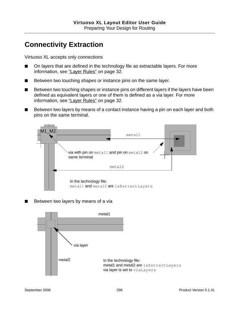
Virtuoso XL Layout Editor User GuidePreparing Your Design for Routing
Connectivity Extraction
Virtuoso XL accepts only connections
■ On layers that are defined in the technology file as extractable layers. For moreinformation, see “Layer Rules” on page 32.
■ Between two touching shapes or instance pins on the same layer.
■ Between two touching shapes or instance pins on different layers if the layers have beendefined as equivalent layers or one of them is defined as a via layer. For moreinformation, see “Layer Rules” on page 32.
■ Between two layers by means of a contact instance having a pin on each layer and bothpins on the same terminal.
■ Between two layers by means of a via
metal2
via with pin on metal1 and pin on metal2 onsame terminal
M1_M2metal1
In the technology file:metal1 and metal2 are lxExtractLayers
metal1
via layer
metal2 In the technology file:metal1 and metal2 are lxExtractLayersvia layer is set to viaLayers
September 2006 296 Product Version 5.1.41

Virtuoso XL Layout Editor User GuidePreparing Your Design for Routing
Note: By default, Virtuoso XL uses symbolic vias defined in the technology file. You can alsodefine physical vias using the Virtuoso layout editor if you need shapes not supported by thesymbolic via. For more information, see “Physical Vias” on page 322.
There are two distinct types of extraction performed by Layout XL.
■ Top-level design extraction, where the extractor extracts only the current top-level design.The extractor’s visibility into the design hierarchy is defined by the extractStopLevelenvironment variable.
You do this by turning on the Connectivity extractor option in the Layout XL Optionsform.
■ Hierarchical extraction, where the extractor extracts either the entire hierarchical designor selected lower-level cellviews from the current top level.
You do this using the Connectivity – Re-Extract Layout command.
Top-Level Design Extraction
The extractor extracts the current top-level design and by default considers only
■ Top-level objects; i.e., shapes, vias, and instances used to implement pins.
■ Instance pins of top-level instances. These pins represent the interface of top-levelinstances to the lower levels in the design and as such are themselves considered to beat the top level.
Extraction Stop Level
The extractStopLevel environment variable increases the extractor’s visibility into thedesign hierarchy. For example,
The greater the extractStopLevel, the more accurate the extraction.
■ Top-level nets that are incomplete with extractStopLevel = 0 may becomecomplete with extractStopLevel > 0.
extractStopLevel Means...
1 extractStopLevel 0 + objects at level 1 + instance pins at level 2
2 extractStopLevel 1 + objects at level 2 + instance pins at level 3
September 2006 297 Product Version 5.1.41

Virtuoso XL Layout Editor User GuidePreparing Your Design for Routing
For example, assume that i0.p0 is an instance pin of top-level instance i0 and r1 is atop-level shape. i0.p0 and r1 are disjoint and on netA, therefore netA is incomplete.
Now increase the extractStopLevel. The extractor sees a lower-level shape i0.r2inside r0. If top-level shape r1 is overlapping i0.r2, then netA becomes complete.
■ There is better detection of shorts between top-level shapes and lower-level shapes.Note that, in this context, the connectivity of a lower-level shape is not the shape net itselfbut the top-level net (if it exists) found by the bottom-up series of terminals and instanceterminals that starts at the shape.
■ There is better detection of shorts between different instances.
Important
Whatever the extractStopLevel, the extractor only ever extracts the current toplevel; i.e., it only ever changes the connectivity of objects or creates markers at thetop level of the design. For information on hierarchical extraction, see “HierarchicalExtraction” on page 298.
The connectivity extractor recognizes connectivity only if all the shapes on a net haveconnectivity information. Otherwise, it reports incomplete nets even though the router reportsthat the design is 100% routed.
To verify that all connections are made in the layout as specified in the schematic, use anAssura® verification product, a Dracula® verification tool, or an Assura hierarchical physicalverification product to run a layout versus schematic (LVS) check on the completed design.
Hierarchical Extraction
Hierarchical extraction in Virtuoso XL lets you extract lower-level cellviews from the currenttop level of the design.
You need to re-extract your design if it was changed after it was last extracted. This canhappen if you modify a lower-level cellview in an application other than Layout XL (forexample, in Layout L) or using a SKILL command which leaves the cellview’s extraction timestamp older than its modification time stamp.
As design is fully re-extracted only when you use the Connectivity – Re-Extract Layoutcommand. This command is enabled when the Connectivity Extractor is switched on in theLayout XL Options form and honors the other extraction settings on that form.
September 2006 298 Product Version 5.1.41
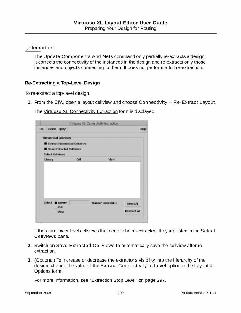
Virtuoso XL Layout Editor User GuidePreparing Your Design for Routing
Important
The Update Components And Nets command only partially re-extracts a design.It corrects the connectivity of the instances in the design and re-extracts only thoseinstances and objects connecting to them. It does not perform a full re-extraction.
Re-Extracting a Top-Level Design
To re-extract a top-level design,
1. From the CIW, open a layout cellview and choose Connectivity – Re-Extract Layout.
The Virtuoso XL Connectivity Extraction form is displayed.
If there are lower level cellviews that need to be re-extracted, they are listed in the SelectCellviews pane.
2. Switch on Save Extracted Cellviews to automatically save the cellview after re-extraction.
3. (Optional) To increase or decrease the extractor’s visibility into the hierarchy of thedesign, change the value of the Extract Connectivity to Level option in the Layout XLOptions form.
For more information, see “Extraction Stop Level” on page 297.
September 2006 299 Product Version 5.1.41

Virtuoso XL Layout Editor User GuidePreparing Your Design for Routing
4. Click OK or Apply.
The top-level design is re-extracted.
Tip
You set the stop level for the extraction and the display options for weak-connect andmust-connect marker violations in the Layout XL Options form.
Re-Extracting Selected Hierarchical Cellviews
To re-extract only selected hierarchical cellviews,
1. From the CIW, open a layout cellview and choose Connectivity – Re-Extract Layout.
The Virtuoso XL Connectivity Extraction form is displayed.
If there are lower level cellviews that need to be re-extracted, they are listed in the SelectCellviews pane.
2. Switch on Save Extracted Cellviews to automatically save the cellview after re-extraction.
myLibmyLib
myCell1myCell2
layoutlayout
September 2006 300 Product Version 5.1.41

Virtuoso XL Layout Editor User GuidePreparing Your Design for Routing
3. (Optional) To increase or decrease the extractor’s visibility into the hierarchy of thedesign, change the value of the Extract connectivity to level option in the Layout XLOptions form.
For more information, see “Extraction Stop Level” on page 297.
4. In the Select Cellviews pane, choose the cellviews you want to re-extract.
You can filter by library name, cell name, and view name or select all of the cellviewslisted. Note that the filter mechanism has no wildcard capability. For example, to select acell called ‘resistor’, you must type ‘r’, ‘re’, ‘res’, and so on. If you type ‘sis’, the cellis not selected.
5. Click OK or Apply to re-extract the selected lower level cellviews.
The selected cellviews are re-extracted all the way up to the top level of the design.
Hierarchical Extraction of Parameterized Cells
For hierarchical connectivity extraction to work for pcells, the connectivity must be defined onthe shapes within the pcell.
You assign connectivity for a pcell shape by descending into the pcell and using theConnectivity – Add Shape to Net command. For more information see “Adding andDeleting Shapes on Nets” in the Virtuoso Layout Editor User Guide.
For more information on pcells, see the Virtuoso Parameterized Cell Reference.
Important
For non-pcells, you assign connectivity interactively using Cadence® SKILLfunctions or using the Connectivity – Assign Nets command. For moreinformation, see “Adding Pins to a Layout” on page 199.
False Overlap and Short Markers
To avoid false overlap and short markers
➤ Add the lxBlockOverlapCheck property to a shape, instance, or instance master.
The lxBlockOverlapCheck property tells the extractor not to check whether a nonoverlaplayer of this shape, instance, or instance master is touching a nonoverlap layer at any cellviewlevel.
September 2006 301 Product Version 5.1.41
Virtuoso XL Layout Editor User GuidePreparing Your Design for Routing
Virtuoso XL does not trace connectivity through floating shapes that are at lower levels ofhierarchy. Connectivity is traced only through the terminals of the lower level blocks. Theprimary reason for this is that a flat, LVS-type approach would significantly impairperformance for large designs.
Via Mosaic Support (CDB only)
The CDB version of Virtuoso XL supports vias and contacts that are implemented asmosaics. The OpenAccess version does not.
Caution
Mosaic instances are supported only for vias and contacts. Mosaicinstances for components are not supported.
You can create, delete, move, and remaster mosaic vias and contacts. You can also changethe numbers of rows and columns in the mosaic.
Via mosaics are considered non-sticky. They are assigned to nets dynamically depending onthe overlaps that are present after each move. If there is no overlap, there is no netassignment, even if you assign the net manually.
Caution
The extractor ignores any lxStickyNet property set on a via mosaic.
Connectivity is propagated through mosaics. For example, shape A on net n1 on layer M1connects to a M1_M2 via mosaic with no net. This via mosaic connects to shape B (with nonet) on layer M2. When you extract the design, Virtuoso XL assigns both the via mosaic andshape B to net n1.
Pseudo-Parallel Connections
A pseudo-parallel connection represents a group of instance terminals on the same net,which need to be physically connected at the current hierarchy level. It is similar to a must-connect; the only difference is that it is implemented not using pins but instance terminals thatbelong to a specified net.
The main advantage of recognizing that a net can be made pseudo-parallel is that it savesspace because there is less routing required to connect up the net.
September 2006 302 Product Version 5.1.41
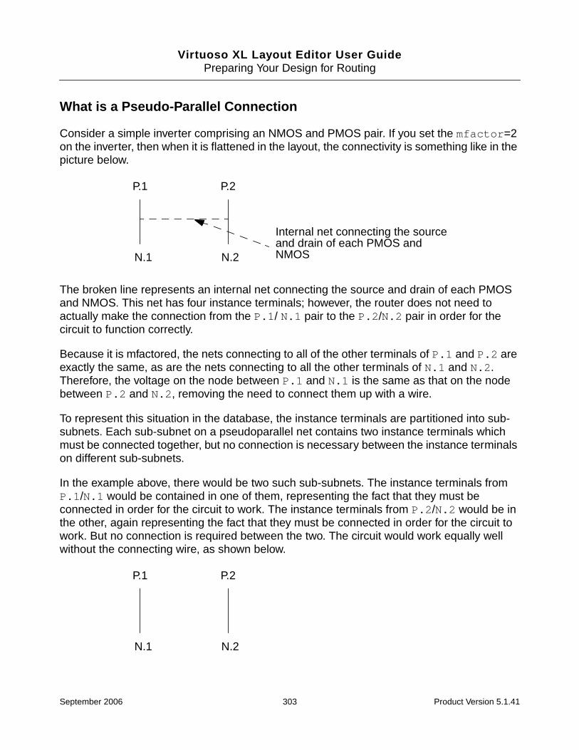
Virtuoso XL Layout Editor User GuidePreparing Your Design for Routing
What is a Pseudo-Parallel Connection
Consider a simple inverter comprising an NMOS and PMOS pair. If you set the mfactor=2on the inverter, then when it is flattened in the layout, the connectivity is something like in thepicture below.
The broken line represents an internal net connecting the source and drain of each PMOSand NMOS. This net has four instance terminals; however, the router does not need toactually make the connection from the P.1/ N.1 pair to the P.2/N.2 pair in order for thecircuit to function correctly.
Because it is mfactored, the nets connecting to all of the other terminals of P.1 and P.2 areexactly the same, as are the nets connecting to all the other terminals of N.1 and N.2.Therefore, the voltage on the node between P.1 and N.1 is the same as that on the nodebetween P.2 and N.2, removing the need to connect them up with a wire.
To represent this situation in the database, the instance terminals are partitioned into sub-subnets. Each sub-subnet on a pseudoparallel net contains two instance terminals whichmust be connected together, but no connection is necessary between the instance terminalson different sub-subnets.
In the example above, there would be two such sub-subnets. The instance terminals fromP.1/N.1 would be contained in one of them, representing the fact that they must beconnected in order for the circuit to work. The instance terminals from P.2/N.2 would be inthe other, again representing the fact that they must be connected in order for the circuit towork. But no connection is required between the two. The circuit would work equally wellwithout the connecting wire, as shown below.
P.1 P.2
N.1
Internal net connecting the sourceand drain of each PMOS andNMOSN.2
P.1 P.2
N.1 N.2
September 2006 303 Product Version 5.1.41
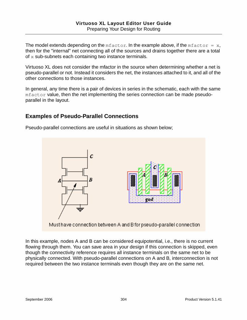
Virtuoso XL Layout Editor User GuidePreparing Your Design for Routing
The model extends depending on the mfactor. In the example above, if the mfactor = x,then for the "internal" net connecting all of the sources and drains together there are a totalof x sub-subnets each containing two instance terminals.
Virtuoso XL does not consider the mfactor in the source when determining whether a net ispseudo-parallel or not. Instead it considers the net, the instances attached to it, and all of theother connections to those instances.
In general, any time there is a pair of devices in series in the schematic, each with the samemfactor value, then the net implementing the series connection can be made pseudo-parallel in the layout.
Examples of Pseudo-Parallel Connections
Pseudo-parallel connections are useful in situations as shown below;
In this example, nodes A and B can be considered equipotential, i.e., there is no currentflowing through them. You can save area in your design if this connection is skipped, eventhough the connectivity reference requires all instance terminals on the same net to bephysically connected. With pseudo-parallel connections on A and B, interconnection is notrequired between the two instance terminals even though they are on the same net.
September 2006 304 Product Version 5.1.41
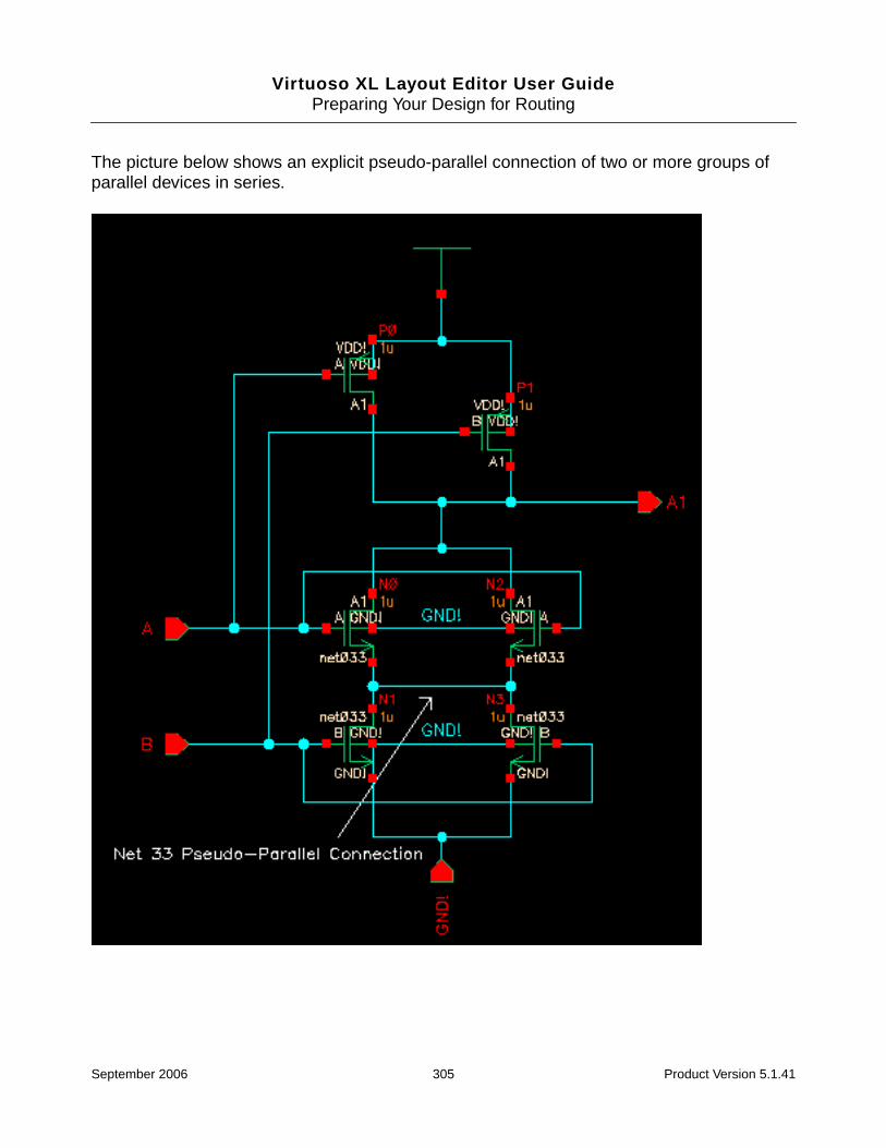
Virtuoso XL Layout Editor User GuidePreparing Your Design for Routing
The picture below shows an explicit pseudo-parallel connection of two or more groups ofparallel devices in series.
September 2006 305 Product Version 5.1.41
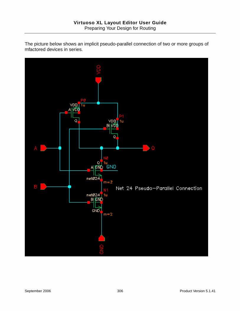
Virtuoso XL Layout Editor User GuidePreparing Your Design for Routing
The picture below shows an implicit pseudo-parallel connection of two or more groups ofmfactored devices in series.
September 2006 306 Product Version 5.1.41

Virtuoso XL Layout Editor User GuidePreparing Your Design for Routing
Important
Both examples show above qualify as pseudo-parallel, but the second example isthe recommended method.
Virtuoso XL automatically finds possible pseudo-parallel connections and treats them assuch when you generate the layout using the Design – Gen from Source command.
If the layout exists already, you can create pseudo-parallel connections automatically byrunning the Connectivity – Update – Components and Nets command.
Alternatively, you can create pseudo-parallel connections manually by
■ Choosing the Connectivity – Define Pins – Pseudo Parallel Connect command.
■ Setting the setPPConn environmental variable.
Defining a Pseudo Parallel Connection
Using the Pseudo Parallel Connect Command
To define a pseudo-parallel connection for a set of instance terminals on a net,
1. From the layout window menu bar, choose Connectivity – Define Pins – PseudoParallel Connect.
The layout window status bar prompts you to click to select a net.
2. Click on the net containing the instance terminals you want to connect.
Flight lines appear between the pins on the specified net that can be pseudo-parallelconnected.
Note: If you were showing incomplete nets, those flight lines are removed automatically.
The layout window prompts you to select an instance terminal.
3. Click on one or more pins of the selected net to select the instance terminals you wantto connect in a pseudo-parallel connection.
The pseudo-parallel connection is defined and the flight lines updated to show theconnection.
4. When you are done, press Esc to cancel the command.
September 2006 307 Product Version 5.1.41

Virtuoso XL Layout Editor User GuidePreparing Your Design for Routing
Instead of selecting nets by clicking in the layout window, you can use the Define PseudoParallel Connected Net form.
To open the form,
1. Press F3 while the Pseudo Parallel Connect command is active.
The Define Pseudo Parallel Connected Net form is displayed. The form lists all of thenets with no I/O pins.
2. In the form, type the name of a net in the Net field or select the net names from the list.
Tip
You can work on more than one net at a time by choosing multiple nets in the formor using drag-by-area when the command line prompts you to select a net.
Note: You must define pseudo-parallel connectivity within a net. You cannot definepseudo-parallel connectivity between nets.
3. When you are done, press Esc to cancel the command.
Tip
You can change between the Must Connect, Strongly Connected, WeaklyConnected, and Pseudo Parallel Connect commands using the right mousebutton.
Using the setPPConn Environment Variable
Setting the setPPConn environmental variable to t automatically identifies nodes that canqualify as pseudo-parallel connections and defines them as such.
To use the setPPConn environment variable,
➤ Add the following line to the .cdsenv file.
layoutXL setPPConn boolean t
Resetting a Pseudo-Parallel Connection
To reset a pseudo-parallel connection,
1. Delete one of the instances in the pseudo-parallel connection.
2. Set the setPPConn environment variable to nil.
September 2006 308 Product Version 5.1.41

Virtuoso XL Layout Editor User GuidePreparing Your Design for Routing
3. Run Connectivity – Update – Components and Nets or rerun Design – Gen FromSource to regenerate the deleted instance.
Generating a Layout without Chaining and Folding on Pseudo-ParallelNets
Pseudo-parallel nets are shown as must-connects when the setPPConn environmentalvariable is set to t and the layout is generated without transistor chaining and folding.
To do this,
1. From the layout window menu bar, choose Design – Gen From Source.
The Layout Generation Options form is displayed.
2. Turn off the Transistor Chaining and Transistor Folding options.
3. Set the rest of the options for your layout and click OK.
September 2006 309 Product Version 5.1.41

Virtuoso XL Layout Editor User GuidePreparing Your Design for Routing
4. Choose Connectivity – Show Incomplete Nets and select the pseudo-parallel net.
Caution
Abutting instances with pseudo-parallel nets is order-dependent. If youmanually abut the instances with the pseudo-parallel nets they will abutcorrectly. If you then abut instances that do not have pseudo-parallel netsthey will not abut and the pseudo-parallel nets that were previouslyabutted will no longer be pseudo-parallel nets.
September 2006 310 Product Version 5.1.41

Virtuoso XL Layout Editor User GuidePreparing Your Design for Routing
Generating a Layout with Chaining and Folding on Pseudo-Parallel Nets
When the lxAllowPseudoParallelNets environment variable is set to t, layoutgeneration optimizes pseudo-parallel nets for implicit pseudo-parallel connections only.
Note: This also works with the Create – Pick from Schematic command.
To do this,
1. Add the following line to your .cdsenv file.
layoutXL lxAllowPseudoParallelNets boolean t
2. From the layout window menu bar, choose Design – Gen From Source.
The Layout Generation Options form is displayed.
3. Turn on the Transistor Chaining and Transistor Folding options.
4. Set the rest of the options for your layout and click OK.
5. To verify that the pseudo-parallel nets are complete, choose Connectivity – ShowIncomplete Nets. Notice that the pseudo-parallel net connection is complete.
Net 24 is optimized
September 2006 311 Product Version 5.1.41

Virtuoso XL Layout Editor User GuidePreparing Your Design for Routing
Using Pick From Schematic with Pseudo-Parallel Nets
You can set pseudo-parallel nets when using the Create – Pick from Schematic commandif
■ The Group As In Schematic option is turned on in the Pick From Schematic form.
■ The nets are internal to the instances created in the scratch cellview.
■ The setPPConn environment variable is set to t.
■ All of the rules for pseudo-parallel nets are met.
For more information, see “Pseudo-Parallel Connections” on page 302.
Layer Selection
When working in the layout window, you can select the layer to work on directly in the LayerSelection Window or you can switch on the automatic tapping options to specify how VirtuosoXL chooses layers during interactive routing using wires, paths, and shapes.
Selecting a Layer in the Layer Selection Window
To select the layer you want to use to connect design components,
➤ In the Layer Selection Window, select the layer you want to use.
September 2006 312 Product Version 5.1.41

Virtuoso XL Layout Editor User GuidePreparing Your Design for Routing
➤ The layer you selected appears in the current display.
Note: The layout window Create – Path command automatically changes the current layerto the layer of the first pin you select to start the path.
Selecting a Layer Automatically when Creating a Rectangle, Polygon, orPath
When you use the Create – Rectangle, Create – Polygon, or Create – Path commandsfrom overlapping shapes, the drawing layer changes automatically to be the same layer asthe shape that you clicked on if Change Layer option on the respective form is switched.
■ The Change Layer option on the Create Path form is controlled by the pathSwitchLayerenvironment variable.
■ The Change Layer options on the Create Polygon and Create Rectangle forms arecontrolled by the shapeSwitchLayer environment variable.
Creating Paths Starting From Overlapping Layers
To change the drawing layer to the same layer as the shape that you first click on,
1. From the layout editor window, choose Create – Path and press F3 to show the CreatePath form.
2. Switch on the Change Layer and Switch Layer Purpose options.
Current layer display
September 2006 313 Product Version 5.1.41

Virtuoso XL Layout Editor User GuidePreparing Your Design for Routing
3. Move your cursor into the layout window and click on a shape.
The LSW updates the current layer to be the same layer as the shape that you clickedon. The purpose of the layer is drawing, which is the first purpose listed in the LayerPurpose Order.
4. Change the Layer Purpose Order in the Create Path form to net pin drawing.
5. Click on a shape in the layout window.
The current layer is the same layer as the shape that you clicked on but now has purposenet.
Creating Rectangles and Polygons Starting From Overlapping Layers
1. Set the shapeSwitchLayer environment variable to t in your .cdsenv file.
layoutXL shapeSwitchLayer boolean t
Note: You can also set the shapeSwitchLayer to t by turning on the Change Layeroption in the Create Rectangle or Create Polygon forms.
2. Choose Create – Rectangle (or Create – Polygon) and move your cursor into thelayout window and click on any shapes that overlap.
The LSW updates the current layer to be the same layer as the shape that you clicked on.
Connecting Nets
To create paths that make the required connections between each device in the layout, youcan use
■ The layout window Create – Path command. The Create – Path command highlightsthe net you are wiring in both the schematic and the layout.
For more information, see “Creating Paths” in the Virtuoso Layout Editor User Guide.
■ Design shapes created by the layout editor: the Create – Rectangle, Create –Polygon, Create – Pin, and Create – Conics commands, which connect two or more
September 2006 314 Product Version 5.1.41

Virtuoso XL Layout Editor User GuidePreparing Your Design for Routing
design elements. For more information, see “Connecting Nets with Design Shapes” onpage 318.
Creating Paths
To create paths follow these steps.
1. From the layout window, choose Create – Path.
2. In the layout window, click where you want the first point of the path.
Virtuoso XL highlights the corresponding net in the schematic and the layout.
Important
You cannot start a path where there is a short.
3. Continue clicking points to draw the path.
Create – Path
Create – Conics – Ellipse
Create – Polygon
Create – Rectangle
Each click drawsanother segment.
✘✘
✘ ✘
1st click
Press Return to closethe path.
The finishedpath appears.
You draw the pathcenterline.
2nd click 3rd click Press Return
September 2006 315 Product Version 5.1.41

Virtuoso XL Layout Editor User GuidePreparing Your Design for Routing
Virtuoso XL creates the path using the layer of the shape where you click first. If you clickwhere there is no shape, Virtuoso XL uses the layer selected in the LSW.
The default width of the path is the minWidth layer property defined in the technologyfile. For more information, see “Physical Rules” on page 34.
4. To change the width of the path, press F3 to display the Create Path options form andtype in the new value in the Width field.
To erase the segments you draw, press the Back Space key.
If you try to start a path or a shape where there is already a path or a shape on morethan one layer, a dialog box appears that shows you what layers are active and asks youto choose one.
The layers listed are determined by the Connectivity Extract to Level option set in theLayout XL Options form, as well as the Display Levels set in the Display Optionsform.
If the Change Layer option is turned off in the Create Path form, then the layer-purposepair is taken from the LSW and the dialog box does not appear. If the Change Layeroption is turned on then the dialog box appears and you must select the layer andpurpose from the dialog box.
The layers listed are determined by the extractStopLevel and thedisplayStopLevel. For more information on displayStopLevel, see AppendixB of the Virtuoso Layout Editor User Guide.
5. To complete the path, press Return on the last point.
Note: Do not double click to end a path. If you have set the layout window Design –Options – Display command to x-first or y-first snap modes, the double click mightmake a notch in the path, which triggers an error message and can cause errors in masklayout.
6. To change the current entry layer, choose a different layer in the LSW.
The current entry layer in the LSW is updated. The path you create uses the new layer.
September 2006 316 Product Version 5.1.41
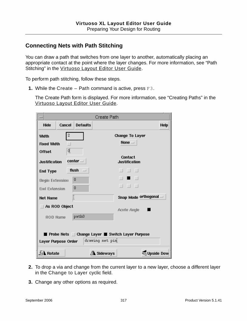
Virtuoso XL Layout Editor User GuidePreparing Your Design for Routing
Connecting Nets with Path Stitching
You can draw a path that switches from one layer to another, automatically placing anappropriate contact at the point where the layer changes. For more information, see “PathStitching” in the Virtuoso Layout Editor User Guide.
To perform path stitching, follow these steps.
1. While the Create – Path command is active, press F3.
The Create Path form is displayed. For more information, see “Creating Paths” in theVirtuoso Layout Editor User Guide.
2. To drop a via and change from the current layer to a new layer, choose a different layerin the Change to Layer cyclic field.
3. Change any other options as required.
September 2006 317 Product Version 5.1.41

Virtuoso XL Layout Editor User GuidePreparing Your Design for Routing
4. On the layout window, click where you want the via placed.
Virtuoso XL places the via between the two layers. The next segment you draw appearson the new layer.
You can then switch back and forth between layers, choosing the new layer from theCreate Path form each time you change layers.
Connecting Nets with Design Shapes
To create design shapes (rectangles, polygons, or conic shapes—circles, ellipses, anddonuts) that you can use to connect devices,
1. From the LSW, choose the layer to use.
2. From the layout window menu, choose the Create command and the design shape youwant (Polygon, for example).
The Create Polygon form is displayed. For more information, see “Creating Polygons” inthe Virtuoso Layout Editor User Guide.
3. Change the Snap Mode to the setting you want.
4. Click to place the first point.
5. Continue clicking points to draw the shape.
Press the Backspace key to undo the previous segment you entered.
September 2006 318 Product Version 5.1.41

Virtuoso XL Layout Editor User GuidePreparing Your Design for Routing
6. To complete the shape, press Return.
Note: The Virtuoso compactor does not compact nonorthogonal shapes or shapes otherthan paths, except for pins.
Checking Connectivity with Flight Lines
To see nets for which connectivity has not yet been made, you can use the Show IncompleteNets command to turn on flight lines in the layout window. Flight lines show incompleteelectrical connections between devices in each net, including
■ Unrouted instance terminals with no pins
■ Unrouted instance terminals with pins that are not extractable
■ Instance terminals with dangling must-join instance pins.
The Command Interpreter Window (CIW) reports how many incomplete nets you have.
For more information on Show Incomplete Nets, see “Identifying Incomplete Nets” in theVirtuoso Layout Editor User Guide.
If you draw a path between two components that completes the connection, the flight linesdisappear. If the path does not complete the connection, the flight lines remain.
➤ To see flight lines in the layout window, from the layout window, choose Connectivity –Show Incomplete Nets.
Press Return to close thepolygon.
✘1st click
✘
Each click drawsanother segment.
✘✘
2nd click4th click
✘
Click left to entereach point.
3rd click
The finished polygonappears.
Press Return
September 2006 319 Product Version 5.1.41

Virtuoso XL Layout Editor User GuidePreparing Your Design for Routing
Checking Connectivity with Markers
Markers are flashing boxes in the layout window that indicate electrical shorts or invalidoverlaps. When the Show Incomplete Nets command is active (flight lines are displayed),the markers might be more difficult to see.
Finding Markers
To find markers, follow these steps.
1. From the layout window menu, choose Verify – Markers – Find.
The Find Marker form is displayed. For more information, see “Finding Markers” in theVirtuoso Layout Editor User Guide.
2. Turn on Zoom To Markers.
3. Click Apply.
Virtuoso XL zooms in on the error and warning markers one by one.
Explaining Markers
To find out what each marker means, follow these steps.
September 2006 320 Product Version 5.1.41

Virtuoso XL Layout Editor User GuidePreparing Your Design for Routing
1. From the layout window, choose Verify – Markers – Explain.
The layout window prompts you to point at a marker.
2. Click on the marker to explain.
A dialog box appears identifying the location and explaining the short.
3. Click on another marker to explain, or press Escape to exit the command.
Deleting Single Markers
To delete (turn off) a single marker, follow these steps.
1. From the layout window, choose Verify – Markers – Delete.
The layout window prompts you to point at a marker.
2. Click on the marker to delete.
The marker disappears.
3. Click on another marker to delete or press Escape to exit the command.
Deleting All Markers
To delete all the markers, follow these steps.
1. From the layout window, choose Verify – Markers – Delete All.
location: (“overview” “feedbackAmp” “layout”)reason: Warning: Overlap between path on layer ‘metal1 drawing’ on net ‘vcc!’ and instance ‘|R17’ creates a short.
September 2006 321 Product Version 5.1.41

Virtuoso XL Layout Editor User GuidePreparing Your Design for Routing
The Delete All Markers form is displayed. Choose the type of markers to delete and thelevels of hierarchy from which you want to delete them. For more information, see“Deleting All Markers” in the Virtuoso Layout Editor User Guide.
2. Indicate your choices on the form.
3. Click OK.
All the markers disappear.
Physical Vias
If you need a via that has more than five layers or one with special shapes not supported bysymbolic vias, you can build a physical via using the layout editor.
Defining a Physical Via
To define a physical via,
1. From the CIW menu bar, choose File – New – Cellview.
September 2006 322 Product Version 5.1.41

Virtuoso XL Layout Editor User GuidePreparing Your Design for Routing
The Create New File form is displayed.
2. Choose the library you want from the Library Name cyclic field and type the cell nameyou want to use in the Cell Name field.
3. Type layout in the View Name field, choose Virtuoso from the Tool cyclic field, andclick OK.
A new layout window appears.
4. From the layout window menu bar, choose Create – Rectangle and draw one via shapeas indicated in the picture below.
5. From the layout window menu bar, choose Create – Pin to create one pin on each ofthe two layers you want to connect. The names of the two pins must be identical.
6. Select the via in the layout window and from the menu bar, choose Design –Properties.
Use Create – Pin to create a pin with terminalname A on layer 1
Use Create – Rectangle to draw a via shape
Use Create – Pin to create a pin with terminalname A on layer 2
September 2006 323 Product Version 5.1.41

Virtuoso XL Layout Editor User GuidePreparing Your Design for Routing
The Edit Cellview Properties form is displayed.
7. Click Property at the top of the form if it is not already selected.
For more information, see “About the Edit Properties Form” in the Virtuoso LayoutEditor User Guide.
8. Click Add.
The Add Property form is displayed.
For more information, see “About the Add Property Form” in the Virtuoso Layout EditorUser Guide.
9. Define the following properties:
September 2006 324 Product Version 5.1.41

Virtuoso XL Layout Editor User GuidePreparing Your Design for Routing
❑ The lvsIgnore property as a boolean with a value of true (see above).
❑ The function property as a string with a value of via.
10. To add each property, click Apply.
The values appear in the Edit Cellview Properties form.
11. Click OK to accept the changes.
12. Choose Design – Save from the layout window menu bar.
The via is saved.
Using Via Mosaics
The CDB version of Virtuoso XL supports vias and contacts that are implemented asmosaics. The OpenAccess version does not.
Mosaic instances for components are not supported on any database.
For more information, see “Via Mosaic Support (CDB only)” on page 302.
September 2006 325 Product Version 5.1.41

Virtuoso XL Layout Editor User GuidePreparing Your Design for Routing
Using the Virtuoso Compactor on a Routed Design
If you want to compact a routed design with the Virtuoso compactor, remember that if you runthe compactor using the layout window Tools – Compact command, the compactorrecognizes symbolic connections only and it cannot compact all of the physical connectionsrecognized by Virtuoso XL.
If you want the compactor to recognize physical connections, as well as symbolicconnections, you must run the compactor when Virtuoso XL is running and use the layoutwindow Compact – Compact command. You might have to stretch the layout windowhorizontally from its Virtuoso XL default size to be able to see the Compact menu on the farright.
To maintain connectivity after compaction if you run the compactor from the Tools menu, youmust use connections made with the Create Path command, use paths with centerlines, andmake sure the centerlines touch the centerlines of other paths to which you want to makeconnections or the connection regions of pins on electrically equivalent layers.
The best way to maintain logical connectivity while compacting a Virtuoso XL design is to setthe syPresvOrigNet property on the design to Preserve Net before compacting.
For more information about the syPresvOrigNet property, see “Logical Connectivity” in theVirtuoso Compactor Reference Manual.
Virtuoso XL wire connectionsrecognized by the compactor(symbolic connections)
Virtuoso XL wire connectionsnot recognized by the compactor(physical connections)
Polygons cannotbe used as wires.
Centerlines donot meet.
September 2006 326 Product Version 5.1.41

Virtuoso XL Layout Editor User GuidePreparing Your Design for Routing
Online Forms
Virtuoso XL Connectivity Extraction
Extract Connectivity to Level specifies how much of the design hierarchy the extractorconsiders when extracting the design. For more information on this option, seeextractStopLevel.
Important
Whatever value you set for Extract Connectivity to Level, the extractor only everextracts the top level; i.e., it only ever changes the connectivity of objects or createsmarkers at the top level of the design. To extract hierarchical cellviews, set the valueof this option to a value great than 0 and use the options in the HierarchicalCellviews group box.
Show Weak-Connect Violations toggles the display of weak-connect violation markers inthe current cellview. If you change the setting, you need to click OK to see the changes in thelayout window.
Show Must-Connect Violations toggles the display of must-connect violation markers inthe current cellview. If you change the setting, you need to click OK to see the changes in thelayout window.
Important
Weak-connect and must-connect markers are updated only if the cellview inquestion is highlighted in the Select Cellviews pane and extracted when the formis applied.
Hierarchical Cellviews lets you extract and save some or all of the hierarchical cellviewsin your design. The options in this group are enabled only when Extract Connectivity toLevel is set to a value other than 0.
Extract Hierarchical Cellviews switches on the extraction of hierarchical cellviews
Save Extracted Cellviews automatically saves the extracted cellviews.
Select Cellviews lists the lower-level cellviews that need to be updated.
Select lets you filter the entries in the list using the library, cell, or view names. Typein the first characters of the names you want to select.
September 2006 327 Product Version 5.1.41

Virtuoso XL Layout Editor User GuidePreparing Your Design for Routing
Note that the filter mechanism has no wildcard capability. For example, to select acell called ‘resistor’, you must type ‘r’, ‘re’, ‘res’, and so on. If you type ‘sis’,the cell will not be selected.
Number Selected indicates the number of cellviews selected.
Select All selects all of the cellviews listed in the Select Cellviews pane.
Deselect All deselects all of the cellviews listed in the Select Cellviews pane
September 2006 328 Product Version 5.1.41

Virtuoso XL Layout Editor User Guide
10Wire Editing
This chapter discusses the following:
■ Introduction
■ Requirements
■ The Wire Editing Environment
■ Enabling Wire Editing
■ Routing Wires
■ Preventing and Checking Design Rule Violations
■ Routing Options and Styles
■ Using Vias
■ Editing Routed Connections
■ Reporting
■ Setting Constraints
■ Troubleshooting
■ Online Forms
September 2006 329 Product Version 5.1.41

Virtuoso XL Layout Editor User GuideWire Editing
Introduction
Wire editing within Virtuoso® XL Layout Editor (Virtuoso XL) environment, allows design rulecorrect interactive routing and editing features.
This section describes
■ Main Features
■ Wire Editing Commands
■ Virtuoso Router to Virtuoso XL Command Mapping
Main Features
The following are the main wire editing features:
■ Route design-rule-correct single and multiple wires based on connectivity
■ Push wires and components while routing
■ Input commands and constraints through a .do file
■ Check existing routes for violations
■ Reshape wire segments
■ Copy existing routes to unrouted connections
■ Generate reports about routing conditions or objects
■ Eliminate notches and removes extra bends in selected wires
■ Compact wires within a selected area
Wire Editing Commands
Command Description
Create – Wire Creates a single wire or multiples wires which are assigned tothe net of the selected connectivity object(s). Wires are createdDRC correct and can push routed wires and paths assigned tonets.
September 2006 330 Product Version 5.1.41

Virtuoso XL Layout Editor User GuideWire Editing
Virtuoso Router to Virtuoso XL Command Mapping
The interactive routing commands of the Virtuoso Router are mapped to the wire editingcommands as follows:
Edit – Wire – Stretch Stretches wire segments while maintaining spacing and widthrules. Pushes routed wires, components, and paths assignedto nets.
Edit – Wire – Split Reshapes wires by cutting and stretching segments whilemaintaining spacing and width rules. Pushes routed wires andpaths assigned to nets.
Edit – Wire – Copy Copies existing wires, including vias, to unrouted connectionsthat have similar lengths and topology.
Edit – Wire – Critic Eliminates notches and removes extra bends in selected wires.
Edit – Wire – Pull Compacts wires within a selected area.
Verify – Check Routing Checks the current cellview for violations based on the optionsselected in the Check Routing form.
Verify – Report Routing Displays the following information:
■ Completion rate
■ Unconnects
■ Conflicts
■ Rule violations
■ Number of pins, components, and vias
■ Length for each routing layer
■ Component or net descriptions
■ Current constraints
■ Technology process rules
Virtuoso Router Wire Editing Commands
Edit Route Create – Wire
Move Edit – Wire – Stretch / Edit – Wire – Split
Command Description
September 2006 331 Product Version 5.1.41

Virtuoso XL Layout Editor User GuideWire Editing
Requirements
Wire editing requires the following.
■ Rule Information
■ Net Connectivity Information
■ Routing Area Boundary
Rule Information
In addition to the Virtuoso XL requirements, you must define which layers and vias are to beused for routing. This information is defined in a rules file or in the technology file.
You can create a rules file interactively using the Rules Editor and either save the ruleinformation to your technology file or to an ASCII file. An ASCII rules file takes precedenceover rules specified in your technology file. To use the rules specified in an ASCII rules file,you can load the file using the Routing Options form, or you can also use environmentvariables to load the rules file.
For more information on using environment variables, see “Using Environment Variables toLoad a Rules File” on page 340.
For more information about Virtuoso XL requirements, see Chapter 2, “Editing YourTechnology File.”
For information about creating a rules file, see “Creating or Editing Rules” in the VirtuosoCustom Placement and Routing Preparation Guide.
Copy Route Edit – Wire – Copy
Cut Segment Edit – Wire – Split
Delete Edit – Delete
Pull Edit – Wire – Pull
Change Edit – Properties
Critic Edit– Wire – Critic
Check Verify – Check Routing
Virtuoso Router Wire Editing Commands
September 2006 332 Product Version 5.1.41
Virtuoso XL Layout Editor User GuideWire Editing
For information about loading a rules file, see “Loading ASCII Rules Files” on page 338.
Note: If the rules file is not loaded or the rule information is not specified in your technologyfile, when you enable the wire editing a warning message is sent to the Command InterpreterWindow:
icclayers are not defined
Net Connectivity Information
Connectivity source requirements are the same as those for the Virtuoso XL.
For more information, refer to “Connectivity and the Requirements” in the Virtuoso CustomPlacement and Routing Preparation Guide.
Routing Area Boundary
The routing area boundary is used to confine the routing to a designated area. By default aboundary is generated by the Gen From Source command. You can also draw a boundaryusing the Create – Rectangle command. When creating a boundary you can specify arouting area boundary per layer, which allows areas of a cellview to be used only by that layer.
For information about defining a boundary layer for a specific routing layer, refer to “DefiningBoundary Layers” in the Virtuoso Custom Placement and Routing Preparation Guide.
For more information about drawing a boundary, refer to “Defining the Design Boundary” onpage 105.
The Wire Editing Environment
This section describes
■ Valid Connectivity Objects
■ Types of Routing Objects
■ Net Assignment
■ Preview Wires and Routing Aids
■ Mouse Button Behavior
■ Grid Controls
■ Using Environment Variables
September 2006 333 Product Version 5.1.41

Virtuoso XL Layout Editor User GuideWire Editing
■ Enabling Wire Editing
■ Virtuoso XL Autorouting
■ Loading ASCII Rules Files
Valid Connectivity Objects
The following are valid connectivity objects used when routing wires.
■ instTerm
■ pin
■ via instance having a pin on each layer and both pins on the same terminal
■ existing wire
■ path assigned to a net
Types of Routing Objects
path
A single layer object. Paths are constructed by defining coordinates, point by point, along acenter line.
wire
A collection of paths and vias, or interconnecting layers, used to connect same net instTermsand pins of the cellview.
route
A collection of paths and vias, or interconnecting layers, used to connect same net instTerms,routes, and pins of the cellview. Depending on the topology, may also include multiplebranches or T junctions.
Note: Virtuoso XL currently does not support route objects.
September 2006 334 Product Version 5.1.41

Virtuoso XL Layout Editor User GuideWire Editing
net
Logical implementation of a single signal or a group of signals that implements theconnections to instance pins and pins. For example:
■ a[0:56] - a net (vectored net).
■ a[0] - a net (scalar net), and a signal.
■ a[0] - a net member of a[0:56]
A net could be defined as A B C[0:7], and the signals defined as A, B, C[0]...C[7].Another net could be defined as C[4:6], with the signals defined as C[4], C[5], and C[6].Signal C[4] is part of both nets, one of which is a bundle that includes a vector and two scalarnets (A B C[0:7]), the other a vector net (C[4:6]).
Also see signal.
net bundle
A collection of nets.
signal
A database object that represents a scalar net. A signal maps to a scalar net and can havethe same name as the scalar net. Signals and nets have different database IDs and they areaccessed through different SKILL functions. From a signal, you can find all the nets that it isassociated with. From a net, you can find all the member signals.
An analogy would be a phone network. The plastic bundle represents the net and the actualcopper wires represents the signals.
Also see net.
Net Assignment
In the Virtuoso environment there are two types of nets, known and unknown nets.
■ known nets: nets that are defined by pins and components (for example clkA).
If a shape which is not assigned to a net touches a shape on known net, the shape isassigned to that net. When the net assignment is defined by pins and components(instTerms), the assignment can not be re-assigned. However, zero level geometry (notinstTerms connections) can be assigned and reassigned as you edit.
September 2006 335 Product Version 5.1.41

Virtuoso XL Layout Editor User GuideWire Editing
If shape on a known net touches another shape on a known net, this will cause a short.
■ unknown nets: shapes that are not assigned to a net
If a shape touches nothing, it is considered a floating net. When floating nets areassigned to a net, they are given the lxStickyNet property. For more information, see“Routing Floating Wires” on page 344.
Sticky Nets
The lxStickyNet property allows a shape to retain the assigned connectivity.
Preview Wires and Routing Aids
While you are routing, a preview wire of the active wire segment stretches from the cursor tothe last point you digitized to show the intended wire. This preview wire is shown as a dashedoutline to indicate the wire-to-wire clearance rule. Small arrows and alignment marks appearwhen the pointer aligns with a nearby wire, pin, or via that is on the net you are routing.
Mouse Button Behavior
■ Clicking the middle button invokes the command-context-specific Layout pop-up menufor wire editing commands.
■ Control-click enables the Cycle Control Wire when routing multiple wires.
■ Shift-click enables the Rotate Bus Cursor when multiple wires.
S-netA D-vdd
G-netB
In this example, known nets are those of the device'sinstTerms (component net assignments, netA, netB,and vdd.The unknown net is the power rail. The power rail isnot connected to the device, and the extractor is freeto assign and reassign the shape to a net.To assign a net to the power rail shape and not allowthe extractor to re-assign to a net, you can assign anet name, such as vdd and the lxStickyNet property isadded automatically. The power rail will retain isconnectivity.As a result of this, if you create a connection betweenS -netA and the power rail shape you will create ashort marker.
Notassignedto a net.
September 2006 336 Product Version 5.1.41

Virtuoso XL Layout Editor User GuideWire Editing
Grid Controls
You can control the grid snapping of wires and vias while wire editing by,
■ using a do file
or
■ selecting either the manufacturing grid or the display grid from the layout menu.
Setting the Grid Using a .do File
To set grid snapping for wires and vias, follow these steps:
1. Create a .do file with the required snap values. For example
# wire grid
grid wire .1 metal2 (direction x) (offset 0)
grid wire .1 metal2 (direction y) (offset 0)
# via grid
grid via .1 (direction x) (offset 0) via1
grid via .1 (direction y) (offset 0) via1
2. Load the .do file.
For more information about loading .do files, see “Loading .do Files” on page 394.
3. Choose Create – Wire from the design window.
Using the above example, metal2 wires will snap to a .1 grid.
Note: There currently is no automatic mapping of the Options – Display – GridControl settings. A do file is required to set grid snapping.
Switch Between the Manufacture Grid and the Display Grid
When routing wires, you can press the middle button to open the Layout pop-up menu andselect either Use manufacturing grid or Use display grid.
The display grid is defined under Options – Display and the manufacturing grid is definedin the technology file.
September 2006 337 Product Version 5.1.41

Virtuoso XL Layout Editor User GuideWire Editing
Using Environment Variables
For a list of environment variables available when wire editing, see “Environment Variables”on page 470.
Enabling Wire Editing
Wire editing is enabled once you have started Virtuoso XL.
For information about starting Virtuoso XL, see Chapter 6, “Generating Your Layout.”
Virtuoso XL Autorouting
You can route a design in batch mode using the Virtuoso XL Routing – Autoroutingcommand. By setting the appropriate options using environment variables in a .cdsenv file,and by providing a do file with routing instructions, you can route the current design withoutexplicitly invoking the router.
For more information, see “About the Autorouting Command” in the Virtuoso CustomPlacement and Routing Preparation Guide.
Loading ASCII Rules Files
Rule information such as the layers and vias to be used when routing, minimum width rules,and the routing direction for layers can be specified in a rules file and saved to yourtechnology file or an ASCII file. By default, the rules in your technology file are used. An ASCIIrules file will take precedence over the rules specified in the technology file.
You can load a rules file through the Routing Options form or by specifying environmentvariables in a .cdsenv file. See “Using Environment Variables to Load a Rules File” onpage 340.
To create a rule file, see “Creating or Editing Rules” in the Virtuoso Custom Placement andRouting Guide.
To load an ASCII rules file through the Routing Options form, follow these steps:
1. From the layout window, choose Options – Routing.
September 2006 338 Product Version 5.1.41
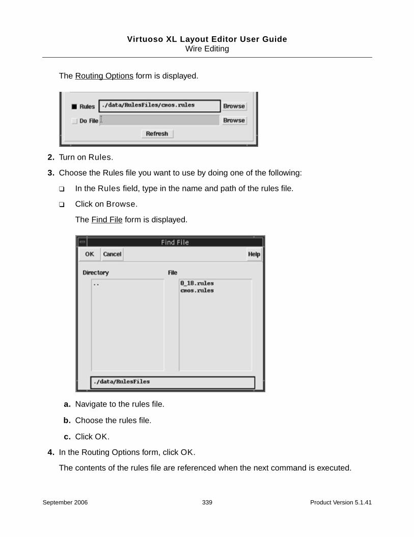
Virtuoso XL Layout Editor User GuideWire Editing
The Routing Options form is displayed.
2. Turn on Rules.
3. Choose the Rules file you want to use by doing one of the following:
❑ In the Rules field, type in the name and path of the rules file.
❑ Click on Browse.
The Find File form is displayed.
a. Navigate to the rules file.
b. Choose the rules file.
c. Click OK.
4. In the Routing Options form, click OK.
The contents of the rules file are referenced when the next command is executed.
September 2006 339 Product Version 5.1.41

Virtuoso XL Layout Editor User GuideWire Editing
Note: Click Refresh in the Routing Options form to reload updated rule information inthe following situations:
❍ Contents the rule file is changed.
❍ Name of the rules file is changed.
❍ A new rules file is being used.
Using Environment Variables to Load a Rules File
You can automate the loading of a rules files by using the following environment variables.
iccTranslator.ExportEditor rulesFile string "ruleFileName"
iccTranslator.ExportEditor useRulesFile boolean t
Routing Wires
Wire editing allows you to create design-rule-correct single or multiple wires betweenconnectivity objects. While routing, you can insert vias to change the routing layer and pushaside wires and paths assigned to nets, depending on the options you have set.
You can use the middle button Layout pop-up menu to access routing options. For detailsabout setting up the routing environment and controlling the routing style, see “RoutingOptions and Styles” on page 349.
This section describes
■ Routing a Single Wire
■ Routing Multiple Wires
■ Routing Floating Wires
Routing a Single Wire
To create a single wire, follow these steps:
1. From the layout window, choose Create – Wire.
September 2006 340 Product Version 5.1.41

Virtuoso XL Layout Editor User GuideWire Editing
When routing wires, you can use the middle button to open the Layout pop-up menu andchange the width of a wire or Matching Wire Width and Pin Widths to the wire you areediting.
2. Do one of the following:
❑ Create a floating wire.
❑ Click or area select a connectivity object. See “Valid Connectivity Objects” onpage 334.
Flight lines appear showing the connectivity of the selected net, and the status bar showsthe name of the selected net.
The option Change Layer in the Create Wire form determines whether the entry layerwill remain on the same layer or switch to the layer of the object you have selected. Bydefault, the routing layer is changed to the same layer as the connectivity object. Whenstarting a wire at a coordinate where there are overlapping layers or from an object withmore than one layer, such as the source or drain of a MOS device, a dialog box appearsshowing you the selectable layers and prompts you to choose one. Turning the ChangeLayer option off disables the dialog box.
3. Digitize points where you want to route the wire.
September 2006 341 Product Version 5.1.41

Virtuoso XL Layout Editor User GuideWire Editing
Wires and vias are prevented from creating violations and will push aside other wires andvias if Push Routing is on. By default, Push Routing is on.
For information about changing layers, see “Changing Layers and Adding Vias” onpage 369.
For information about violation checking, see “Preventing and Checking Design RuleViolations” on page 345.
4. Finish the wire by doing one of the following:
❑ From the Layout pop-up menu, choose Finish Routing.
The connection is finished from the last digitized point. An area for the wire must liewithin the routing search area or the automatic operation is terminated. Someconnections may require layer changes and vias to be added in order to finish theconnection.
❑ Continue digitizing points to complete one or more connections.
❑ Double click or press Return.
The wire is terminated where the cursor is positioned.
Note: To erase the segments you draw, press the Backspace key. Each time you pressBackspace, the last digitized segment is deleted.
Routing Multiple Wires
You can route arbitrary wire sets, buses, differential pairs, and bundles. All multiple wirerouting is considered bus routing. Differential pairs and bundles retain their association afterrouting is completed. In general, only connections that use the same layers and vias can berouted together. The exception is tandem layer routing.
For details about setting up the routing environment and controlling the routing style forbuses, refer to “Routing Options and Styles” on page 349.
When routing multiple wires, follow these steps:
1. From the layout window, choose Create – Wire.
The layout window prompts you to enter a point or select an area to start the wire.
2. Select adjacent pins, vias, existing wires, or paths assigned to nets.
You can Shift-click to add additional objects to your selection set.
September 2006 342 Product Version 5.1.41

Virtuoso XL Layout Editor User GuideWire Editing
Flight lines appear showing the connectivity of the selected nets, and the status bannershows the names of the selected nets.
Note: Enable Bus Routing must be turned on in the Routing Options form Bus tab.The default setting for Enable Bus Routing is on.
To select multiple wires on the same net, turn on Allow Same Net Picking. For moreinformation, see “Allow Same Net Picking” on page 344.
3. Digitize points where you want to route the wire.
Wires starting from pins that are not at minimum spacing are gathered to the minimumseparation at the first digitized point. To gather bus wires before the first digitized point,you can turn gathering bus wires on and also specify the spacing of wires.
When routing multiple wires, the pointer attaches to a control wire. Cycling the controlwire can help you when you are changing the routing direction to avoid obstacles.
For more information about change layers, see “Using Vias Patterns on Multiple Wires”on page 370.
4. Finish the wires by doing one of the following:
❑ From the Layout pop-up menu, choose Finish Routing.
The connections are finished from the last digitized point. Some connections mayrequire layer changes and vias to be added in order to finish the connection. An areafor the wire must lie within the routing search area or the automatic operation isterminated.
❑ From the Layout pop-up menu, choose Route As Many As Possible.
If routing space is limited to fewer than all the wire segments of the set, you canchoose to automatically drop the wires that cannot be routed, or have no newsegments added. For more information, see “Working with Insufficient RoutingSpace” on page 356.
❑ From the Layout pop-up menu, choose Route Only If All Succeed.
No new segments are added if there is insufficient routing space for all the wires ofthe set.
❑ Continue digitizing points to complete one or more connections.
❑ Double click or press Return.
The wires will ended where the cursor is positioned.
Note: To erase the segments you draw, press the Backspace key. Each time you click
September 2006 343 Product Version 5.1.41
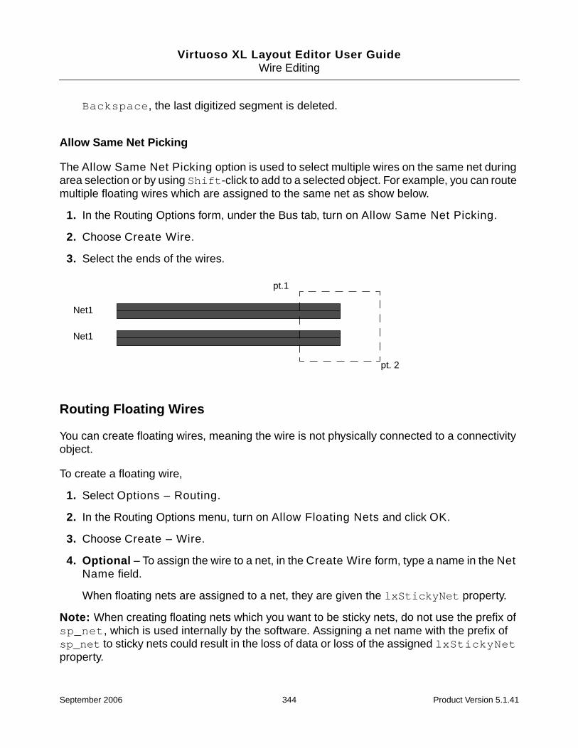
Virtuoso XL Layout Editor User GuideWire Editing
Backspace, the last digitized segment is deleted.
Allow Same Net Picking
The Allow Same Net Picking option is used to select multiple wires on the same net duringarea selection or by using Shift-click to add to a selected object. For example, you can routemultiple floating wires which are assigned to the same net as show below.
1. In the Routing Options form, under the Bus tab, turn on Allow Same Net Picking.
2. Choose Create Wire.
3. Select the ends of the wires.
Routing Floating Wires
You can create floating wires, meaning the wire is not physically connected to a connectivityobject.
To create a floating wire,
1. Select Options – Routing.
2. In the Routing Options menu, turn on Allow Floating Nets and click OK.
3. Choose Create – Wire.
4. Optional – To assign the wire to a net, in the Create Wire form, type a name in the NetName field.
When floating nets are assigned to a net, they are given the lxStickyNet property.
Note: When creating floating nets which you want to be sticky nets, do not use the prefix ofsp_net, which is used internally by the software. Assigning a net name with the prefix ofsp_net to sticky nets could result in the loss of data or loss of the assigned lxStickyNetproperty.
Net1
Net1
pt.1
pt. 2
September 2006 344 Product Version 5.1.41

Virtuoso XL Layout Editor User GuideWire Editing
For information about net assignment and sticky nets, see “Net Assignment” on page 335.
Preventing and Checking Design Rule Violations
Wire editing supersedes DRD Editing. Wires created or edited are not checked for violationsinteractively in DRD Editing. Violations are displayed as post-edit markers at the end of thecommand, when post-edit DRD checking is on.
This section describes
■ Interactive Checking
■ Same Net Checking
■ Checking Regions
■ Checking Route and Pin Violations
Interactive Checking
Prevent clearance rule violations between routing objects such as wires, vias, and pins whilerouting by doing the following:
1. From the layout window, choose Options – Routing.
The Routing Options form is displayed.
2. Turn Interactive Checking on.
Conflicts and design rule violations such as clearance rules are not allowed. InteractiveChecking also prevents routing outside of the boundary area.
Note: When you are in an active command, you can turn interactive checking on bychoosing Turn checking on from the Layout pop-up menu.
September 2006 345 Product Version 5.1.41
Virtuoso XL Layout Editor User GuideWire Editing
You can check for specific types of routing and pin violations through the Check Routingform. For more information, see “Checking Route and Pin Violations” on page 347.
Same Net Checking
By default, same net violations are not checked. Prevent same net violations such as gaps,notches, and self-intersecting nets by doing the following:
Note: The Same Net Checking option can slow the performance of wire editing. In bestpractice, this should be used after you have finished all routing and before running finalverification on your design.
1. From the layout window, choose Options – Routing.
2. The Routing Options form is displayed.
3. Turn Same Net Checking on.
Same net gaps, notches, self intersecting nets, or loops are not allowed.
You can check for existing same-net violations through the Check Routing form. For moreinformation, see “Checking Route and Pin Violations” on page 347.
Checking Regions
Check Region controls whether wire segments are checked at region boundaries when youare creating or editing wires. A region is a routing area where you want different clearancesor width rules to apply. For more information about creating regions, see “Creating Regions”on page 347.
When Check Region is on, wire segments are halted at a region boundary until you click atthe boundary. A pseudopin is inserted for each net, and then you can continue routing ormoving the wire segments into or out of the region. If you are routing multiple wires that arenot part of a bundle or differential pair, the wires fan out to accommodate different width orclearance rules.
When Check Region is off, region boundaries and rule differences are ignored when youroute or move wire segments into or out of a region.
Control checking of regions by doing the following:
1. From the layout window, choose Options – Routing.
2. The Routing Options form is displayed.
September 2006 346 Product Version 5.1.41

Virtuoso XL Layout Editor User GuideWire Editing
3. Turn Check Region on.
Creating Regions
Define routing areas where you want different clearances or wire widths by creating a .do filewith region and clearance rules. Region rules have the highest precedence in the rulehierarchy; therefore, the region clearance and width rules override all other clearance andwidth rules.
To define a region, follow these steps:
1. Create a .do file to define a region and assign rules to the region using the followingsyntax.
Choose the shape (rectangle or polygon), specify its layer and location, and assign theclearance rules and width rules you want to apply within the region. You can also assignan optional region name. For example:
define (region REG1 (rect metal1 10.5 2.75 55.05 5.5) (rule (width .8)(clearance 1.2 (type via_wire))))
You can assign rules for the entire region, for a single class or net within the region, orbetween two classes within the region.
For more information about using the define command to create regions, see Define– Region – By Coordinates in the Virtuoso Chip Assembly Router UserReference.
2. Load the .do file.
For more information about loading .do files, see “Loading .do Files” on page 394.
Checking Route and Pin Violations
Use the Check Routing form to control which rule violations and pin data problems arechecked and graphically marked.
To check specific types of violations, doing the following:
1. From the layout window, choose Verify – Check Routing.
September 2006 347 Product Version 5.1.41

Virtuoso XL Layout Editor User GuideWire Editing
The Check Routing form is displayed.
2. Turn on the options you want to check.
3. Click OK.
The checking process is initiated.
Checking Violation Markers
Violations will appear as markers, which can be checked using the Verify – Markers – Findcommand.
To check markers, see “Checking Connectivity with Markers” on page 320.
September 2006 348 Product Version 5.1.41
Virtuoso XL Layout Editor User GuideWire Editing
Routing Options and Styles
This section describes
■ Matching Wire Width and Pin Widths
■ Matching Wire Width and Pin Widths for Multiple Wires
■ Gathering Bus Wires
■ Spacing for Gathered Bus Wires
■ Overriding Bus Spacing
■ Rotating the Bus Cursor
■ Cycling the Control Wire
■ Working with Insufficient Routing Space
■ Allowing Redundant Wiring
■ Allowing Orthogonal Jogs
■ Route To Cursor
■ Using Alternate Views
■ Connecting Multiple Component Pins
■ Pushing Routes and Components
■ Routing Shielded Nets
■ Routing Tandem Layer Pairs
■ Showing Length Rules Constraints
Matching Wire Width and Pin Widths
Matching the wire width and pin width can be set with using the following layoutenvironment variables in the .cdsenv file or through menu items.
Setting the Wire Width to Match a Pin or Wire Using Environment Variables
matchPinWidth Sets the width of the active wire segment to the widthof the selected pin.
September 2006 349 Product Version 5.1.41

Virtuoso XL Layout Editor User GuideWire Editing
Preserving the Match Width
When matchWidthSticky is t, matchPinWidth, matchWireWidth,matchPinWidthValue values are not reset when new wire editing session is started orwhen a new Create Wire command is performed.
Setting the Wire Width to Match a Pin or Wire Using Menu Items
To set the wire width to match a pin or an existing wire, follow these steps:
1. From the layout window, choose Create – Wire.
matchPinWidthValue Sets the width of the active wire segment to the widthof the narrow or wide edge of the selected pin and isactive only when matchPinWidth is t.
matchTargetPinWidth Sets the width of the active wire segment to the widthof the narrow or wide edge of the target pin.
matchTargetPinWidthValue Sets the width of the active wire segment to the widthof the narrow or wide edge of the target pin and isactive only when matchTargetPinWidth is t.
matchWidthSticky Preserves the matchPinWidth, matchWireWidth,and matchPinWidthValue values.
The following will occur if matchPinWidth,matchWireWidth, matchPinWidthValuematchTargetPinWidth,matchTargetPinWidthValue values are set, andmatchWidthSticky is t,
When the wire is finished the subsequent Create Wirecommand or session will not reset the environmentvariables to the default.
The environment variables values are pre-set for thefirst Create Wire session.
matchWireWidth Sets the width of the active wire segment to the widthof the wire segment you are editing.
September 2006 350 Product Version 5.1.41

Virtuoso XL Layout Editor User GuideWire Editing
The Create Wire form is displayed.
Note: You can also use the middle button to open the Layout pop-up menu and chooseany of the matching options once the Create – Wire command is active.
2. Click or area select the pin or existing wire to be routed.
3. Do one of the following:
❑ To match the wire width to the width of the pin you are editing, turn on Match PinWidth and either choose Narrow, which matches the wire width to the shortest sideof the pin, or Wide which matches the wire width to the longest side of the pin.
❑ To match the wire width to the width of the wire you are editing, choose Match WireWidth.
The width change is not implemented if it introduces a clearance violation.
September 2006 351 Product Version 5.1.41
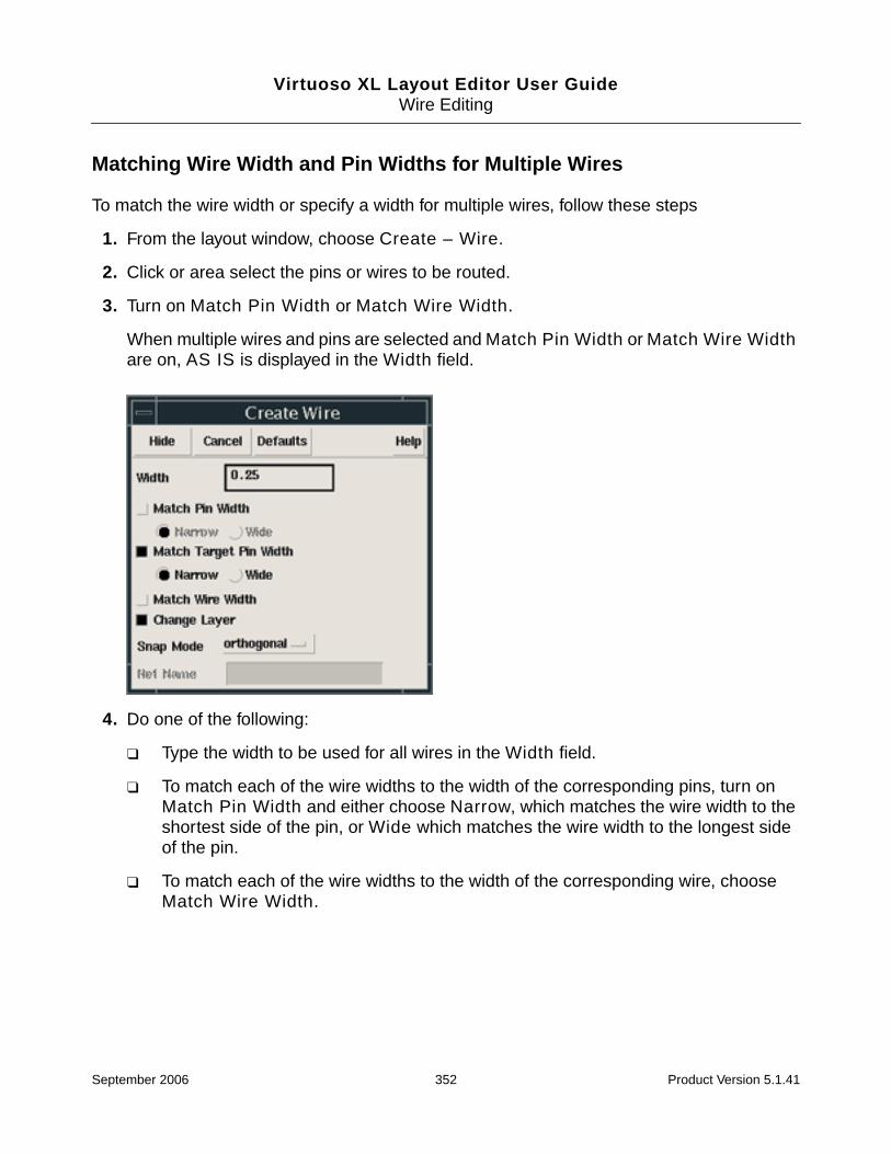
Virtuoso XL Layout Editor User GuideWire Editing
Matching Wire Width and Pin Widths for Multiple Wires
To match the wire width or specify a width for multiple wires, follow these steps
1. From the layout window, choose Create – Wire.
2. Click or area select the pins or wires to be routed.
3. Turn on Match Pin Width or Match Wire Width.
When multiple wires and pins are selected and Match Pin Width or Match Wire Widthare on, AS IS is displayed in the Width field.
4. Do one of the following:
❑ Type the width to be used for all wires in the Width field.
❑ To match each of the wire widths to the width of the corresponding pins, turn onMatch Pin Width and either choose Narrow, which matches the wire width to theshortest side of the pin, or Wide which matches the wire width to the longest sideof the pin.
❑ To match each of the wire widths to the width of the corresponding wire, chooseMatch Wire Width.
September 2006 352 Product Version 5.1.41

Virtuoso XL Layout Editor User GuideWire Editing
Gathering Bus Wires
Wires starting from pins that are not at minimum spacing are gathered to the minimumseparation at the first digitized point. You can gather bus wires and change the spacingbetween wires before digitizing points by doing the following.
➤ From Layout pop-up menu, choose Turn gather bus wires on.
The bus cursor changes and the wires are gathered to the minimum spacing rule. Youcan change the orientation of the bus cursor by using the Rotate Bus Cursor command.
Spacing for Gathered Bus Wires
You can change the default wire-to-wire spacing for gathered bus wires. You might want tochoose spacing based on the via pattern you use when you change layers and add vias. Formore information, refer to “Adding Vias to Gathered Bus Wires” on page 371.
1. From the Layout pop-up menu, choose Set up.
September 2006 353 Product Version 5.1.41
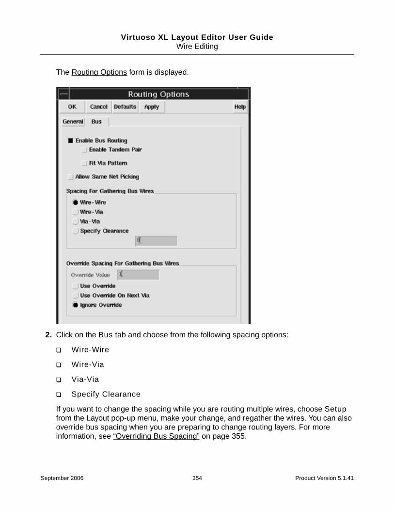
Virtuoso XL Layout Editor User GuideWire Editing
The Routing Options form is displayed.
2. Click on the Bus tab and choose from the following spacing options:
❑ Wire-Wire
❑ Wire-Via
❑ Via-Via
❑ Specify Clearance
If you want to change the spacing while you are routing multiple wires, choose Setupfrom the Layout pop-up menu, make your change, and regather the wires. You can alsooverride bus spacing when you are preparing to change routing layers. For moreinformation, see “Overriding Bus Spacing” on page 355.
September 2006 354 Product Version 5.1.41

Virtuoso XL Layout Editor User GuideWire Editing
Overriding Bus Spacing
You can override the current spacing for gathered bus wires and make the spacing changetake place immediately on the layer you are routing, or you can have the change take placewhen you add a via pattern and change routing layers.
1. From the Layout pop-up menu, choose Set up.
The Routing Options form is displayed.
2. Do one of the following:
❑ If you want the new spacing to take effect immediately on the current routing layer,choose Use Override and type a new spacing value in the Override Value field.
❑ If you want the new spacing to take effect on the next routing layer after you add avia pattern, choose Use Override On Next Via and type a new spacing value inthe Override Value field.
3. Click OK.
September 2006 355 Product Version 5.1.41

Virtuoso XL Layout Editor User GuideWire Editing
Note: If you want to return to the default spacing value while routing the multiple wires,choose Ignore Override.
Rotating the Bus Cursor
When you gather wires, the bus cursor automatically orients perpendicular to the set of activewire segments.
To rotate the cursor, do the following:
➤ While routing, press Control-right-click.
The cursor will toggle back and forth between horizontal and vertical each time you pressControl-right-click.
After you rotate the bus cursor, the cursor orientation stays fixed for the current routes. Ifyou want to change the orientation, you must use the command again.
Cycling the Control Wire
As you are routing multiple wires, your cursor points to a wire segment called the control wire.The control wire serves as a pivot point and allows you to control the position of via patternsby changing which wire segment the cursor attaches to as you route the set of wires. Bydefault, the center wire is the control wire and is visually identified by a white outline on theend of the control wire.
To cycle the control wire, do the following:
➤ While routing, press Shift-right-click.
Repeatedly using this command cycles the control wire between the two outermost wiresand the center wire of the set.
Working with Insufficient Routing Space
If there is insufficient routing space for all the wires of a multiple wire set, you can drop wiresand finish routing a portion of the wires or have no new wire segments added.
To drop wires and route a portion of the wire set, do the following:
➤ From the middle button Layout pop-up menu, choose Route As Many As Possible.
As many wires as possible are routed and the rest are dropped. The dropped wires arereplaced by guides drawn from the last digitized locations to pins on their respective nets
September 2006 356 Product Version 5.1.41

Virtuoso XL Layout Editor User GuideWire Editing
and you can continue routing a subset of wires. However, even with the option set on, nonew segments are added if there is insufficient space to route at least one wire of the set.
If wires are dropped you can use the Picking Up Dropped Wires command to restartthe set from a new location and reroute the dropped wires.
To have no new segments added, do the following:
➤ From the Layout pop-up menu, choose Route Only If All Succeed.
No new segments are added if there is insufficient routing space for all the wires of theset.
Picking Up Dropped Wires
If you chose Route As Many As Possible from the Layout pop-up menu, wires that cancause violations are dropped as you route a multiple wire set. You can restart some or all ofthe dropped wires at the currently digitized location of the set. Only the wires that do notintroduce violations are restarted, and guides are drawn from the new locations back to thelocations from which these wires were dropped. You can then route the set of picked up wiresfrom the new locations.
To route the dropped set of wires, follow these steps:
1. Click to digitize the locations of the undropped wires.
2. From the Layout pop-up menu, choose Pick Up Dropped Wires.
All the wires of the set that do not create violations restart at locations consistent with thecurrently digitized locations.
3. Continue routing the set of wires.
4. After you complete the routing of the dropped wires, you must route each dropped wirefrom the location where it was dropped to the location where it was restarted.
Allowing Redundant Wiring
Redundant wiring requires two steps. The first step is creating wire. The second step isediting the wire and creating a loop or crossing over the wire by adding an additional wire.This is considered redundant wiring and by default is not allowed. You might need redundantwires on selected nets for increased current capacity or to create power rings. Redundantwiring is permitted on nets when Allow Redundant Wiring On Enabled Nets is turned onand the allow_redundant_wiring rule is attached to the net.
September 2006 357 Product Version 5.1.41

Virtuoso XL Layout Editor User GuideWire Editing
Note: Self intersecting wires are allowed by default. When you create a wire and cross overthe wire in one step, this is considered a same-net violation and by default is not checked. Formore information about same net violations, see “Same Net Checking” on page 346.
To allow redundant wiring, follow these steps:
1. Create a .do file with the following syntax:
rule net netName (allow_redundant_wiring on)
You can also apply the allow_redundant_wiring rule to a class of nets. For example:
rule class className (allow_redundant_wiring on)
2. Load the .do file.
For more information about loading .do files, see “Loading .do Files” on page 394.
3. From the Routing Options form, turn Allow Redundant Wiring On Enabled Nets on.
Wire loops are allowed on nets with the attached allow redundant wiring rule.
Allowing Orthogonal Jogs
You can permit orthogonal jogs in existing wires when they are pushed with the Create Wire,Stretch Wire, and Pull commands by selecting Allow Orthogonal Jogs. The PushRouting option must be on to enable wire pushing. By default, Allow Orthogonal Jogs isturned on.
To permit orthogonal jogs, do the following:
➤ From the Routing Options form, turn Allow Orthogonal Jogs on.
To prevent orthogonal jogs, do the following:
➤ From the Routing Options form, turn Allow Orthogonal Jogs off.
Note: Also see Route To Cursor.
Figure 10-1 Orthogonal Jogs
September 2006 358 Product Version 5.1.41
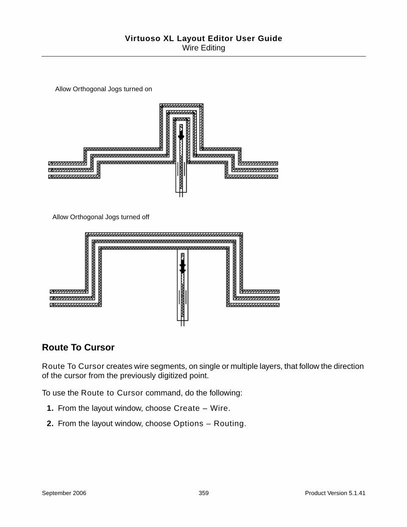
Virtuoso XL Layout Editor User GuideWire Editing
Route To Cursor
Route To Cursor creates wire segments, on single or multiple layers, that follow the directionof the cursor from the previously digitized point.
To use the Route to Cursor command, do the following:
1. From the layout window, choose Create – Wire.
2. From the layout window, choose Options – Routing.
Allow Orthogonal Jogs turned on
Allow Orthogonal Jogs turned off
September 2006 359 Product Version 5.1.41

Virtuoso XL Layout Editor User GuideWire Editing
The Routing Options form is displayed.
3. Turn Route To Cursor on.
Note: To avoid unexpected jogs, press the Shift key when routing to cursor. Pressing andholding the Shift key constraints the mouse motion which help to keep the x or y coordinatesunchanged.
Single Layer
To route multiple wire segments on a single layer, do the following:
1. Turn Single Layer on and click Apply.
2. Click or area select a connectivity object (pin, via, or an existing wire).
The multi-segment wire is routed on the active layer and follows the direction of thecursor.
Multiple Layers
To route wires on multiple layers, do the following:
1. Turn Multiple Layers on and click Apply.
September 2006 360 Product Version 5.1.41

Virtuoso XL Layout Editor User GuideWire Editing
2. Click or area select a connectivity object (pin, via, or an existing wire).
The wire follows the cursor and changes layers. Vias are added automatically as layerschange.
For example, when routing a metal1 wire and crossing over another metal1 wire with thecursor, wires will not be pushed, the layer is changed, and a via is automatically inserted.
Follow Layer Direction
To route wires that follow the layer directions set in the rules file, do the following:
1. From the Routing Options form, turn Multiple Layers on.
2. Turn Follow Layer Direction on and click Apply.
3. Click or area select a connectivity object (pin, via, or an existing wire).
First digitized point
Second digitized point
September 2006 361 Product Version 5.1.41

Virtuoso XL Layout Editor User GuideWire Editing
The wires are routed on multiple layers, vias are added automatically as layers change,and the layer direction set in the rules file is strictly enforced.
For example, when the routing direction in the rules file is as follows:
metal1 vertical
metal2 horizontal
When routing from a metal1 pin in the horizontal direction, the layer direction is strictlyfollowed; a via is inserted and the wire is routed on metal2. The layer direction continues tobe followed as the wire is routed and vias are automatically inserted as the layer directionchanges.
Note: The Route To Cursor setting is not available when you are routing a bus, bundle, ordifferential pair.
Using Alternate Views
You can use the Alternate Views option in the Routing Options form to specify views otherthan the layout view, such as an abstract view of your data. If you have abstract views,choosing to use them rather than the layout views can make run time faster because there ismuch less data to be processed by the software.
First digitized point
Second digitized point
September 2006 362 Product Version 5.1.41

Virtuoso XL Layout Editor User GuideWire Editing
Connecting Multiple Component Pins
Multiple Component Connection lets you connect multiple component pins (terminals ofcomponents) or top level component pins (instance pins) to the same net.
Use the Create Wire command to connect multiple same net component pins that are inalignment by clicking on the two outermost pins. The resulting wire contains connections toeach pin and separate wire segments between each adjacent pair of pins.
Note: If the pins are not in alignment, a single wire is created with connections only to thepins that are clicked on. Shape pins (top-level shapes that are also pins) are consideredio_ports and will not be connected using the Multiple Component Connection option.
For more information, see “Pins” in the Virtuoso Custom Placement and RoutingPreparation Guide.
Pushing Routes and Components
Push Routing
Push Routing controls whether wires and vias are pushed aside while routing to maintaincurrent clearance rules. By default Push Routing is on.
The Create – Wire, Stretch Wire, and Split Wire commands can be used to push wires.
To control pushing of wires, do the following:
1. From the layout window, choose Options – Routing.
The Routing Options form is displayed.
2. Turn Push Routing off or on.
Note: When Push Routing is on, use Allowing Orthogonal Jogs to control whether
Connects components creating separate wire segments.
September 2006 363 Product Version 5.1.41
Virtuoso XL Layout Editor User GuideWire Editing
orthogonal jogs are allowed in the nets you are pushing.
Pushing Components
Push Component controls whether components are pushed aside while routing if there isinsufficient space to route the wire.
Only the Stretch Wire command can be used to push components.
To control pushing of components, do the following:
1. From the layout window, choose Options – Routing.
The Routing Options form is displayed.
2. Turn Push Component off or on.
Components are pushed aside only if there is insufficient routing space. If there issufficient routing area for the wires you are routing, the wires are routed around thecomponent, rather than push the component.
Routing Shielded Nets
The Auto Shield option automatically routes shield wires around nets that have a shield ruleattached to the net.
To route shielded nets, follow these steps:
1. Create a .do file using the circuit and rule commands to assign shielding rules tothe net.
Choose the type of shield (parallel, tandem or coax), specify the net to be used as ashield, and assign the overhang, width and gap rules you want to apply. For example:
circuit net NET5 (shield on (type parallel) (use_net GND))
rule net NET5 (tandem_shield_overhang 1.5)
rule net NET5 (shield_width 1)
rule net NET5 (shield_gap 1.5)
For more information about shielding rules, refer to shield_descriptor in the VirtuosoChip Assembly Router User Reference.
2. Load the .do file.
For more information about loading .do files, see “Loading .do Files” on page 394.
3. From the Routing Options form, turn Auto Shield on.
September 2006 364 Product Version 5.1.41
Virtuoso XL Layout Editor User GuideWire Editing
4. From the layout window, choose Create – Wire.
5. Click or area select a connectivity object (pin, via, or an existing wire) of the net you wantto shield.
6. Digitize points where you want to route the wire.
7. Finish the wire by doing one of the following:
❑ From the Layout pop-up menu, choose Finish Routing.
The connection is finished from the last digitized point. An area for the wire must liewithin the routing search area or the automatic operation is terminated. Someconnections may require layer changes and vias to be added in order to finish theconnection.
❑ Double click or press Return.
The selected net is automatically routed with a shield.
The shield command requires sufficient clearance around the wires to be shielded.Wherever there is insufficient space, the command leaves a gap in the shield wire.
8. Tie down the shielding net to the source.
The shielding net is left floating and must to be manually connected to the source.
Routing Tandem Layer Pairs
To route tandem layer pairs, follow these steps,
1. From the layout window, choose Create – Wire.
The layout window prompts you to enter a point or select an area to start the wire.
2. From the Layout pop-up menu, choose Set up.
3. Click the Bus tab.
4. Turn on Enable Tandem Pair.
5. Click or area select the adjacent connectivity objects of the layer pairs you want to route.
The Choose which layer to use form is displayed.
6. Choose a layer and click OK.
Wires are routed on both layers.
7. Digitize points where you want to route the wire.
September 2006 365 Product Version 5.1.41

Virtuoso XL Layout Editor User GuideWire Editing
The wires are gathered and overlaid at the first digitized point.
Showing Length Rules Constraints
To display wire lengths relative to length rules as you are routing wires,
1. Create a .do file using the circuit command to assign length rules to the net.
For example:
circuit net NET5 (length 6)
circuit net CK (length 14 5)
Minimum and maximum rules can be set.
2. Load the .do file.
For more information about loading .do files, see “Loading .do Files” on page 394.
3. From the Routing Options form, Show Timing/Length Rule Constraints field, turn onMeter, Octagons, or both Meter and Octagons.
4. From the layout window, choose Create – Wire.
5. Click or area select a connectivity object (pin, via, or an existing wire) of the net which isassigned the length rule.
6. Digitize points where you want to route the wire.
Note: Rectangles are not included in length rule calculations, only wires are consideredwhen displaying length rules. The wire length is calculated from pin-edge to pin-edge.
Using the Meter Display
September 2006 366 Product Version 5.1.41

Virtuoso XL Layout Editor User GuideWire Editing
The meter indicator displays the status of the wire length relative to minimum and maximumlength limits for the wire. The meter indicator consists of a horizontal line with two vertical tick-marks labeled MIN and MAX. These marks indicate the minimum and maximum length limits.As you create a wire with assigned length rules, an X appears on the horizontal line at aposition relative to the MIN and MAX marks. The X indicates the current wire length relativeto minimum and maximum length rules for the net.
If the current wire length is between the minimum and maximum length limits, there is nolength rule violation. If the X is to the left of the MIN mark or to the right of the MAX mark, thecurrent wire length violates the minimum or maximum length rule. If you set only a minimumor only a maximum length rule, the meter graphic displays a single MIN or a single MAX limitline. Also, you might not see both limit lines, if the current wire position is too far from one ofthe limits. The line for the rule limit you are closest to is always displayed.
A signed number appears above the MIN or MAX limit mark and indicates the distance to theclosest length limit. The displayed number switches from one limit line to the other as youroute the current wire across the midpoint distance. Negative numbers mean the currentlength is below a limit, and positive numbers mean that the current length is above a limit. Thenumber is displayed in green if length rules are not violated and in red if any length rule isviolated.
September 2006 367 Product Version 5.1.41
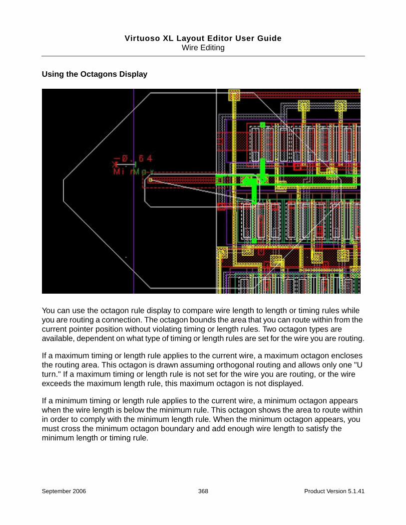
Virtuoso XL Layout Editor User GuideWire Editing
Using the Octagons Display
You can use the octagon rule display to compare wire length to length or timing rules whileyou are routing a connection. The octagon bounds the area that you can route within from thecurrent pointer position without violating timing or length rules. Two octagon types areavailable, dependent on what type of timing or length rules are set for the wire you are routing.
If a maximum timing or length rule applies to the current wire, a maximum octagon enclosesthe routing area. This octagon is drawn assuming orthogonal routing and allows only one "Uturn." If a maximum timing or length rule is not set for the wire you are routing, or the wireexceeds the maximum length rule, this maximum octagon is not displayed.
If a minimum timing or length rule applies to the current wire, a minimum octagon appearswhen the wire length is below the minimum rule. This octagon shows the area to route withinin order to comply with the minimum length rule. When the minimum octagon appears, youmust cross the minimum octagon boundary and add enough wire length to satisfy theminimum length or timing rule.
September 2006 368 Product Version 5.1.41

Virtuoso XL Layout Editor User GuideWire Editing
The minimum octagon is calculated by assuming orthogonal routing and by allowing only one"U turn." After the wire you are routing exceeds the minimum length or if no minimum lengthrule applies, this octagon is not displayed.
If you are editing a net that has a net timing or length rule, the Manhattan lengths of all guidewires of the net contribute to the current net length.
Using Vias
You can change layers and add vias while routing individual wires or you can change viapatterns while routing multiple wires.
This section describes
■ Changing Layers and Adding Vias
■ Using Vias Patterns on Multiple Wires
■ Adding Vias to Gathered Bus Wires
■ Legal Via Sites
■ Rotating Vias
■ Minimum Number of Cuts
■ Pseudo Vias
■ Stacking Vias
Changing Layers and Adding Vias
To change layers and add a via while routing, do one of the following:
■ From the Layout pop-up menu, choose Add Via.
The Add Via form is displayed and all available vias and routing layers that can bereached from the current routing layer are displayed. Choose the applicable layer youwant to switch to or choose a via type on the layer.
Inaccessible layers are grayed out.
Note: You can control whether you can add a via to the current layer without changinglayers when using the Add Via form with the allowViaOnCurrentLayer environment
September 2006 369 Product Version 5.1.41
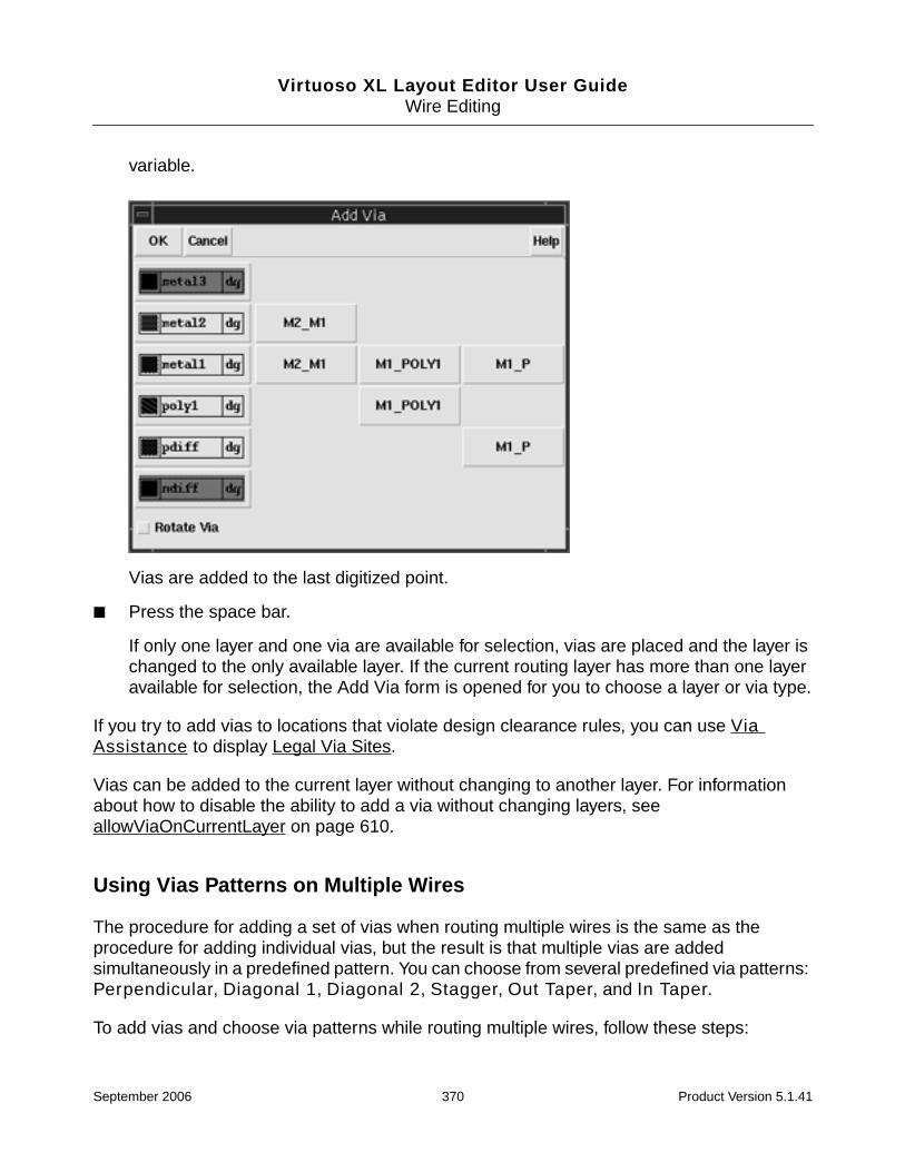
Virtuoso XL Layout Editor User GuideWire Editing
variable.
Vias are added to the last digitized point.
■ Press the space bar.
If only one layer and one via are available for selection, vias are placed and the layer ischanged to the only available layer. If the current routing layer has more than one layeravailable for selection, the Add Via form is opened for you to choose a layer or via type.
If you try to add vias to locations that violate design clearance rules, you can use ViaAssistance to display Legal Via Sites.
Vias can be added to the current layer without changing to another layer. For informationabout how to disable the ability to add a via without changing layers, seeallowViaOnCurrentLayer on page 610.
Using Vias Patterns on Multiple Wires
The procedure for adding a set of vias when routing multiple wires is the same as theprocedure for adding individual vias, but the result is that multiple vias are addedsimultaneously in a predefined pattern. You can choose from several predefined via patterns:Perpendicular, Diagonal 1, Diagonal 2, Stagger, Out Taper, and In Taper.
To add vias and choose via patterns while routing multiple wires, follow these steps:
September 2006 370 Product Version 5.1.41

Virtuoso XL Layout Editor User GuideWire Editing
1. From the Layout pop-up menu, choose Via Pattern.
The Via Pattern Pop-up appears.
2. Click the icon of the via pattern you want to use.
Diagonal 1 is the default via pattern. The display indicates how the pattern would beplaced for the current routing direction.
If the selected via pattern cannot be placed, single circles are displayed indicating thevia site are not legal. Use the Fit Via Pattern option to search for nearby available viasites for those vias that have clearance conflicts. For more information, refer to Legal ViaSites.
Adding Vias to Gathered Bus Wires
The following are guidelines for adding vias to gathered buses.
When the bus wire spacing is set to the following:
■ wire-via
Use any via pattern except the perpendicular pattern to keep the wires from spreading.
■ via-via
Use all patterns without spreading the wires.
■ wire-wire
All via patterns are likely to spread the wires (if the wire-wire clearance rules specify thesmallest spacing possible).
After the vias are added, the wires will gather back to minimum wire spacing.
September 2006 371 Product Version 5.1.41

Virtuoso XL Layout Editor User GuideWire Editing
Note: For non-gathered bus wires, if the required via spacing differs from the minimum wirespacing, the wires are spread to accommodate the via spacing and the new via pitch is usedas the new wire spacing.
Legal Via Sites
A legal via site is a location where you can add a via during routing and not violate designclearance rules.
When the add via operation fails, you can use Via Assistance to display legal via sites.When vias are placed using Via Assistance, via pattern resembles the original pattern butwith some via positions modified. If Snap or Display are turned on, legal via sites aredisplayed as concentric circles. Single circles are via sites that are not reachable from thecurrent digitized location.
■ If Via Assistance is off, no via sites are displayed when you try to add a via to an illegalsite.
■ If Snap is on and the digitized point is within one via radius of a legal site, the tool routesto the legal via site and adds a via. If it is not within one via radius, legal via sites aredisplayed and no via is added.
■ If Display is on and the last digitized point is a legal site, a via is added. If it is not a legalvia site, nearby legal via sites are displayed and no via is added.
Rotating Vias
Use the Rotate button on the Add Via form to rotate vias 90 degrees as you place them. Ifthe last digitized point is on or within one via radius of a legal site, a rotated via (or via patternfor multiple wires) is added automatically. Otherwise, the legal via sites in the area aredisplayed (when Via Assistance is on), and you can click one of them to add the rotated viaor via pattern.
September 2006 372 Product Version 5.1.41

Virtuoso XL Layout Editor User GuideWire Editing
Note: If you are routing multiple wires, all the rectangular vias of the via pattern are rotated.
Minimum Number of Cuts
The minimum number of cuts rule specifies the number of cuts a via must have when it is ona wide wire or pin whose width is greater than minWidth.
The minNumCut rule is stored in the technology file as tableSpacing, one-dimension tableindexed by width inside the physicalRules section. The rule is specified only for layers withmaterial type li or cut:
For more information, see the Technology File and Display Resource File ASCII SyntaxReference Manual or “Technology File Class physicalRule” in the Virtuoso CustomPlacement and Routing Guide.
Pseudo Vias
Pseudo vias are used in the case of two layers that are self-conducting. They are defined inyour rules file and used internally by Virtuoso XL but never appear in the DFII database.
For information about defining pseudo vias in a rules file, see “Local Interconnects (PseudoVias)” in the Virtuoso Custom Placement and Routing Preparation Guide.
Using Default Vias
The environment variable layout useDefaultVia is supported when using Route toCursor or Finish Routing. When useDefaultVia is t, you can specify which of multiplevias is the default by adding the device property in the technology file, for example:
tfcDefineDeviceProp(
; (viewName deviceName propName propValue)
( symbolic M1M2 t )
( symbolic M1M2TYPE2 defaultVia t )
( symbolic M2M3TYPE2 defaultVia t )
) ;tfcDefineDeviceProp
The viaNameTYPE2 vias are automatically picked. If useDefaultVia is set to nil, thena popup will appear when multiple vias are available, to allow you to choose which one to use.
September 2006 373 Product Version 5.1.41

Virtuoso XL Layout Editor User GuideWire Editing
Stacking Vias
To stack vias, do the following:
1. Create a .do file using the rule command to allow via stacking.
For example:
rule IC (stack_via any_overlap (stack_cut))
For more information about length rules, refer to the Virtuoso Chip Assembly RouterUser Reference.
2. Load the .do file.
For more information about loading .do files, see “Loading .do Files” on page 394.
3. From the layout window, choose Create – Wire.
4. From the Layout pop-up menu, choose Add Via.
The Add Via form is displayed and all available vias and routing layers that can bereached from the current routing layer are displayed.
5. From the Add Via form select the correct via on an adjacent layer.
Note: You are allowed to choose a layer that is not adjacent to the current layer, however,this does not allow you to choose a via. In most cases your design rules will require youto place vias with extended overlaps when stacking vias. To stack specific vias you muststack each via individually.
6. Once the first via is placed, again from the Layout pop-up menu, choose Add Via.
7. From the Add Via form select the correct via on an adjacent layer.
You can continue to place and stack vias. Via stacking adheres to the stack via depthrule, prMaxStackVias.
Editing Routed Connections
■ Stretching Wires and Vias
■ Splitting and Stretching Wires
■ Copying Routes
■ Removing Notches and Extra Wire Bends
■ Compacting Wires Using Pull
September 2006 374 Product Version 5.1.41

Virtuoso XL Layout Editor User GuideWire Editing
Stretching Wires and Vias
When using the Stretch Wire command, you can stretch a wire segment while maintainingthe minimum spacing and width rules, and push aside existing wires.
To stretch a wire segment follow, these steps:
1. Choose Edit –Wire – Stretch.
The layout window prompts you to select a figure to be stretched and the design windowshows the active command as Stretch Wire.
2. Click or area select the wire you want to stretch.
3. Move the cursor and click to place the wire.
The following options affect the Stretch Wire command.
■ Interactive Checking
When Interactive Checking is on, wires are prevented from creating violations.
■ Push Routing
When Push Routing is on, the stretched wire will push aside other wires and vias.
■ Push Components
When Push Component is on, the stretched wire will push aside components if there isinsufficient space to stretch the objects.
■ Allow Orthogonal Jogs
When Allow Orthogonal Jogs and Push Routing are on, orthogonal jogs are createdin wires that you are pushing.
Note: Press the Escape key to terminate the Stretch Wire command.
Splitting and Stretching Wires
The Split Wire command reshapes wires by cutting and stretching segments whilemaintaining spacing and width rules. The steps include cutting selected segments, using theright mouse button to cycle to the segments you want to stretch, and stretching the segmentsto the final position.
To split and stretch wires, follow these steps:
1. Choose Edit – Wire – Split.
September 2006 375 Product Version 5.1.41
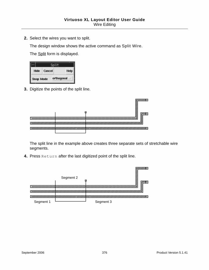
Virtuoso XL Layout Editor User GuideWire Editing
2. Select the wires you want to split.
The design window shows the active command as Split Wire.
The Split form is displayed.
3. Digitize the points of the split line.
The split line in the example above creates three separate sets of stretchable wiresegments.
4. Press Return after the last digitized point of the split line.
Segment 1
Segment 2
Segment 3
September 2006 376 Product Version 5.1.41

Virtuoso XL Layout Editor User GuideWire Editing
5. Choose the segments you want to stretch by clicking the right button and cycling througheach set of wire segments.
6. Stretch the wire segments to the new location and click to place the segments.
The following options affect the split command.
■ Interactive Checking
When Interactive Checking is on, the stretched wire segments are prevented fromcreating violations.
Cursor attaches to segment 3
Segment 3
Right click and the cursor attaches to segment 2
Segment 2
Right click again and the cursor attaches to segment 1
Segment 1
September 2006 377 Product Version 5.1.41

Virtuoso XL Layout Editor User GuideWire Editing
■ Push Routing
When Push Routing is on, the stretched wire segments will push aside other wires andvias.
■ Allow Orthogonal Jogs
When Allow Orthogonal Jogs and Push Routing are on, orthogonal jogs are createdin wires that you are pushing.
Copying Routes
You can copy existing wires and vias (complete or incomplete connections, but not floatingnets) to unrouted connections that have similar lengths and topologies. You can copy singlewires to one or more target pins or a set of wires, and you can mirror the copied wires alongthe x axis and y axis.
To copy a single route or multiple routes, follow these steps:
1. Choose Edit – Wire – Copy.
The layout window prompts you to select the route to be copied.
2. Select the route you want to copy.
The layout window prompts you to select the next route segment or point to thedestination location.
❑ Click once to select one segment of a route.
❑ Shift-click to add additional route segments to your selection.
❑ Double click to select the entire route.
If rule checking is turned on, the copy is successful only if it does not cause clearancerule violations.
Note: If the copied wire has a t-junction, only the wire segments up to the t-junction canbe selected for copying. You cannot pick the entire wire. T-junctions might introduceambiguous routing topologies that can cause the command to fail.
3. From the Layout pop-up menu, choose Mirror – X, – Y or – XY to mirror the copied route.
4. Click on a target pin to place the copied route.
When you copy a single wire to a target pin with different width or clearance rules, thetool applies these rules to the copied wire.
September 2006 378 Product Version 5.1.41

Virtuoso XL Layout Editor User GuideWire Editing
Removing Notches and Extra Wire Bends
The Critic Wire command eliminates notches and removes extra bends in routed wires byattempting to adjust the existing wires rather than reroute the wire. You can use the CriticWire command on a single wire or a group of wires.
To remove notches and extra bends from wires, do the following:
1. Choose Edit – Wire – Critic.
2. Select a wire or group of wires.
September 2006 379 Product Version 5.1.41
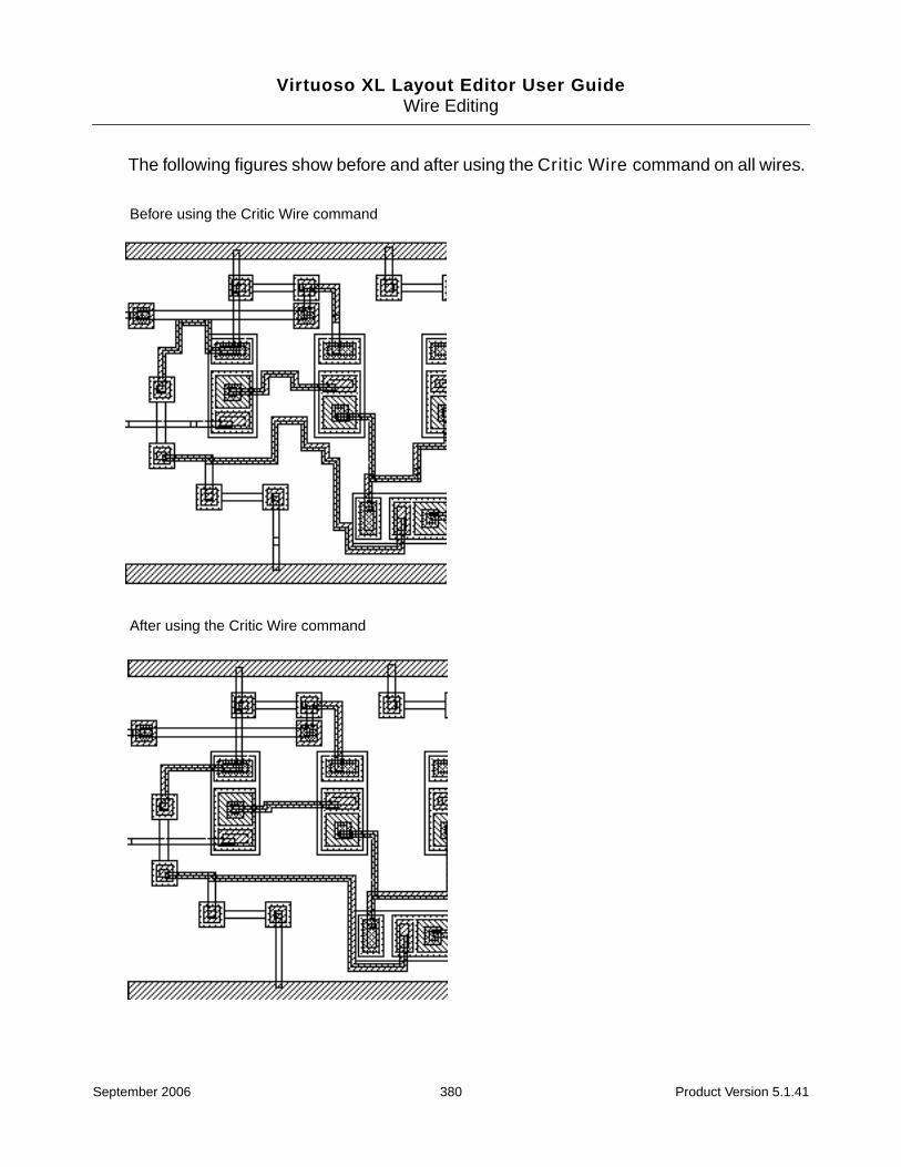
Virtuoso XL Layout Editor User GuideWire Editing
The following figures show before and after using the Critic Wire command on all wires.
Before using the Critic Wire command
After using the Critic Wire command
September 2006 380 Product Version 5.1.41

Virtuoso XL Layout Editor User GuideWire Editing
Compacting Wires Using Pull
The Pull command compacts wires and vias within a rectangular area. The compaction areais defined by digitizing a starting point and ending point, which creates a pull bar, and thendigitizing a third point, which completes the definition of the compaction area. The pull bar isused to pull the routes in a vertical or horizontal direction.
To compact wires and vias within an area, do the following:
1. Choose Edit – Wire – Pull.
2. Set a pulling bar by doing one of the following:
❑ Digitize a starting point, move the pointer vertically, and click to define the end pointsof a vertical pulling bar.
❑ Digitize a starting point, move the pointer horizontally, and click to define the endpoints of a horizontal pulling bar.
A vertical or horizontal line represents the pulling bar.
3. Sweep the pointer away from the pulling bar in either orthogonal direction.
As you sweep the pointer, the wires and vias are pulled toward the pulling bar.
4. Click when the pointer defines the compaction area you want to use.
The following options will affect the how the wires are compacted:
■ Interactive Checking
When Interactive Checking is on, the compaction is limited by clearance and spacingrules. Pulling stops for a particular wire or via if a violation would occur.
When Interactive Checking is off, rules are not observed, and the pulling tends to pileup the wires at or near the pulling bar.
■ Allow Orthogonal Jogs
When Allow Orthogonal Jogs and Push Routing are on, orthogonal jogs are createdfor any wire segment that passes through the compaction area. Wire segments withinthe area are pulled, while wire segments outside are not.
When Allow Orthogonal Jogs is off, the entire wire segment is pulled.
September 2006 381 Product Version 5.1.41

Virtuoso XL Layout Editor User GuideWire Editing
Reporting
This section describes
■ Displaying Routing Status Reports
■ Displaying Network Reports
■ Displaying Component Reports
■ Displaying Net Reports
■ Creating Rules Reports
■ Search Reports
■ Saving Reports
You can display reports, which give you detailed information about routing status, networkinformation, a specified component, a specified net, and current design rules. You can alsosave reports in text files.
To display reports, follow these steps:
1. Choose Verify – Report Routing.
September 2006 382 Product Version 5.1.41

Virtuoso XL Layout Editor User GuideWire Editing
The Reports form is displayed.
Displaying Routing Status Reports
Routing reports contain a routing summary and a table of design statistics by layer. Therouting summary includes information about the completion rate, unconnects, wiring, and theconflicts and rule violations encountered.
To display a Route Status report, do the following:
1. From the Report form, click the General tab.
2. Turn Route Status on.
3. Click OK.
September 2006 383 Product Version 5.1.41

Virtuoso XL Layout Editor User GuideWire Editing
The Routing Status Report window appears.
For descriptions of the information contained in the report, see “Route Status Report Window”on page 406.
Displaying Network Reports
Network reports contain design statistics, which include the number of pins, vias, t-junctions,conflicts, and length information for each routing layer.
To create a Network Report, do the following:
1. From the Report form, click the General tab.
2. Turn Network on.
3. Choose Length By Layer or Total Lengths.
September 2006 384 Product Version 5.1.41

Virtuoso XL Layout Editor User GuideWire Editing
Length By Layer displays the report with the nets sorted by the length of the layers.Total Length lets you display the report with the nets sorted by Name, Ratio, Length,or Extra.
4. Click OK.
The Network Report window appears.
The report identifies the nets in the current design and how the netlist was sorted.
For descriptions of the information contained in this report, refer to “Network Report Window”on page 407.
Displaying Component Reports
Component report contain information about a single component in the design.
To create a Component report, do the following:
1. From the Report form, click the Component tab.
September 2006 385 Product Version 5.1.41

Virtuoso XL Layout Editor User GuideWire Editing
The tab lists components in the current design.
2. Choose the component from the list for which you want to create a report.
3. Click OK.
September 2006 386 Product Version 5.1.41

Virtuoso XL Layout Editor User GuideWire Editing
The Instance Report window appears.
For descriptions of the information contained in this report, refer to “Instance Report Window”on page 408.
Displaying Net Reports
Net reports contain information about a single net in the design.
To create a Net report, do the following:
1. From the Report menu, click the Net tab.
September 2006 387 Product Version 5.1.41

Virtuoso XL Layout Editor User GuideWire Editing
The tab lists nets in the current design.
2. Choose a net from the list for which you want to create a report.
3. Click OK.
September 2006 388 Product Version 5.1.41
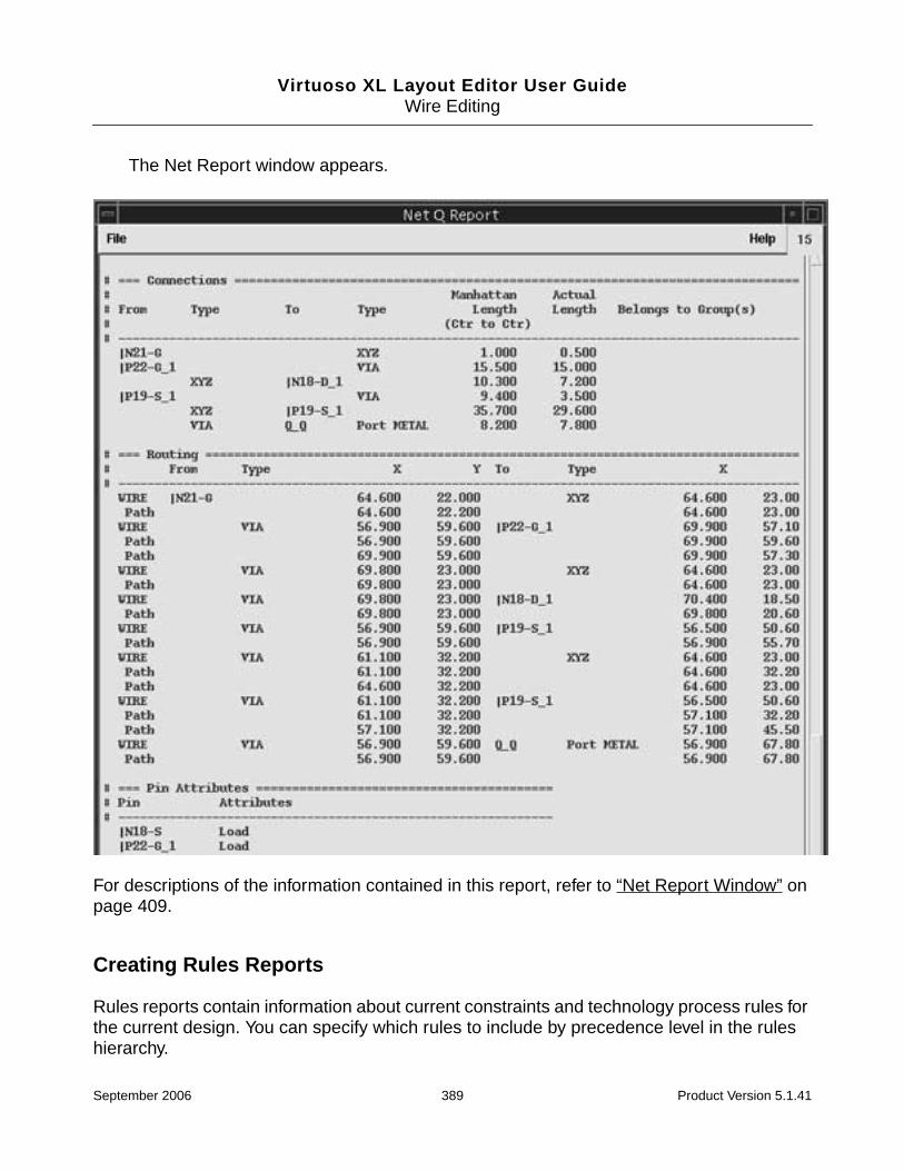
Virtuoso XL Layout Editor User GuideWire Editing
The Net Report window appears.
For descriptions of the information contained in this report, refer to “Net Report Window” onpage 409.
Creating Rules Reports
Rules reports contain information about current constraints and technology process rules forthe current design. You can specify which rules to include by precedence level in the ruleshierarchy.
September 2006 389 Product Version 5.1.41

Virtuoso XL Layout Editor User GuideWire Editing
To create a Rules report, do the following:
1. From the Report form, click the Rules tab.
The form updates.
2. Choose All or Specify.
You can list all the design rules in the current design or you can specify which rules toinclude by precedence level in the rules hierarchy.
3. Click OK.
September 2006 390 Product Version 5.1.41
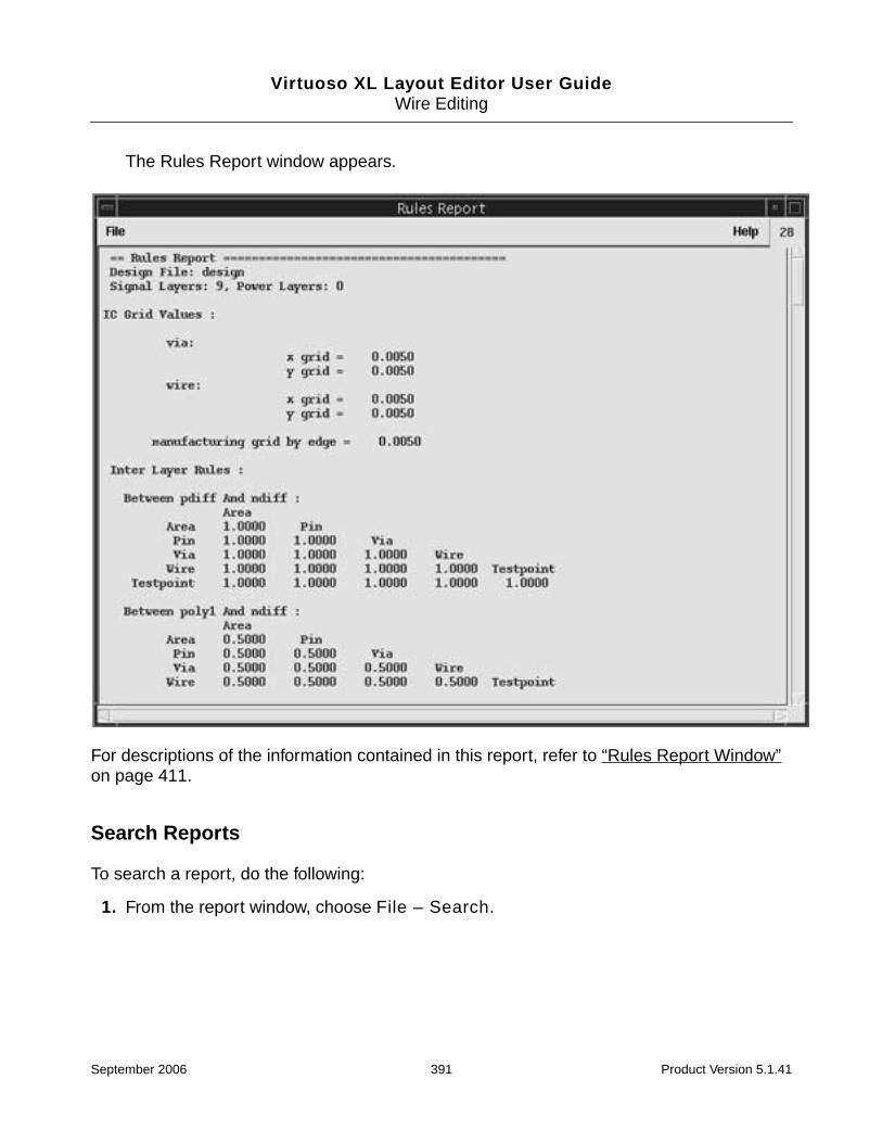
Virtuoso XL Layout Editor User GuideWire Editing
The Rules Report window appears.
For descriptions of the information contained in this report, refer to “Rules Report Window”on page 411.
Search Reports
To search a report, do the following:
1. From the report window, choose File – Search.
September 2006 391 Product Version 5.1.41

Virtuoso XL Layout Editor User GuideWire Editing
The Search form is displayed.
2. In the Search for field, type the specific words, strings, or regular expressions.
3. Click OK.
Saving Reports
To save the report in a text file, do the following:
1. From the report window, choose File – Save As.
The Save As form is displayed.
2. In the File Name field, type a name for the text file.
Note: You can include the path to the file if you want to specify a directory other than thecurrent working directory.
3. Click OK.
Setting Constraints
This section describes
September 2006 392 Product Version 5.1.41

Virtuoso XL Layout Editor User GuideWire Editing
■ Using the Virtuoso Constraint Manager
■ Using .do Files
Using the Virtuoso Constraint Manager
Use the Virtuoso Constraint Manger to set net-based constraints which, once they are savedto the cellview, are followed when routing.
The following are net-based constraints you can apply using the constraint manager.
■ Net or Class
❑ Control the order in which nets or classes are routed.
❑ Control the width of nets or classes.
■ Net To Net / Shielding
❑ Set the minimum distance between two nets on different layers.
❑ Create tandem shielding.
❑ Create parallel shielding.
❑ Create differential pairs.
■ Class To Class
❑ Set the minimum distance between nets on different layers.
■ Class To Net
❑ Set the minimum distance between nets on different layers.
Note: If you create or modify a constraint while in a wire editing command, you will need torestart the command to make the constraint active.
For more information, see the Virtuoso Constraint Manager User Guide.
Using .do Files
A .do file is an external ASCII file you can create using any text editor. In the Virtuoso XLenvironment, .do files are used to apply constraints and definitions. In contrast, .do filesused in the Virtuoso Custom Router and Cadence® Chip Assembly Router environment canbe used as a script to drive a batch job.
September 2006 393 Product Version 5.1.41
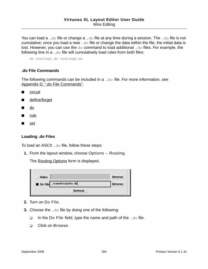
Virtuoso XL Layout Editor User GuideWire Editing
You can load a .do file or change a .do file at any time during a session. The .do file is notcumulative; once you load a new .do file or change the data within the file, the initial data islost. However, you can use the do command to load additional .do files. For example, thefollowing line in a .do file will cumulatively load rules from both files:
do routing1.do routing2.do
.do File Commands
The following commands can be included in a .do file. For more information, seeAppendix D, “.do File Commands”.
■ circuit
■ define/forget
■ do
■ rule
■ set
Loading .do Files
To load an ASCII .do file, follow these steps:
1. From the layout window, choose Options – Routing.
The Routing Options form is displayed.
2. Turn on Do File.
3. Choose the .do file by doing one of the following:
❑ In the Do File field, type the name and path of the .do file.
❑ Click on Browse.
September 2006 394 Product Version 5.1.41

Virtuoso XL Layout Editor User GuideWire Editing
The Find File form is displayed.
a. Navigate to the .do file.
b. Choose the .do file.
c. Click OK.
4. In the Routing Options form, click OK.
The contents of the .do file are referenced when the next command is executed.
Note: Click Refresh in the Routing Options form to reload updated .do file informationin the following situations:
❍ Contents of the .do file is changed.
❍ Name of the .do file is changed.
❍ New .do file is being used.
Note: Verify constraints and rules set in the current design by using the Verify – ReportRouting command. For more information, refer to “Creating Rules Reports” onpage 389.
September 2006 395 Product Version 5.1.41

Virtuoso XL Layout Editor User GuideWire Editing
Online Forms
Add Via
Displays vias and routing layers that have been defined in the rules file or technology file. Youcan either choose the layer you want to change to or choose a via type on the layer.
The Add Via form consists of a matrix of layer and via buttons in rows and columns. Eachrow in the matrix represents a routing layer and contains a button for the layer and buttons forthe vias that can reach that layer from the current layer. The first column contains the buttonsfor the layers. The other columns contain buttons for each available via type for the givenlayer. The buttons are color coded by layer color, and the layer name appears on each layerbutton.
Buttons for layers that can be reached from the current active layer are enabled, while buttonsfor inaccessible layers are grayed out.
Rotate Via rotates vias 90 degrees as you place them.
Check Routing
Rules
Conflict checks for shorts and clearance violations.
Crosstalk checks for crosstalk rule violations. To control crosstalk, limit the lengths ofparallel wire segments for a given wire-to-wire gap. The parallel_segment crosstalkrule limits the distance that wire segments on the same layer can be parallel, and thetandem_segment crosstalk rule limits the distance that wire segments on adjacentlayers can be parallel.
Limit Way checks for limit_way rule violations. The limit_way rule defines themaximum wrong-way distance permitted in a connection. The wrong way direction isvertical on horizontal routing layers and horizontal on vertical routing layers.
Maximum Process Wire Width checks for maximum process width rule violations.
Minimum Mask Edge Length checks for the minimum dimension for any edge of ashape at the mask level.
Miter checks for unmitered corners.
Polygon Wire checks for clearance violations from polygon wire shapes to pins, fixedwires, protected wires, and fixed or protected vias.
September 2006 396 Product Version 5.1.41

Virtuoso XL Layout Editor User GuideWire Editing
Re-Entrant Path checks for wire loops that have been created while routing or editing.
Segment checks for maximum segment rule violations. The max_segment rulecontrols the total routed length on a layer.
Use Layer checks for use_layer rule violations. The use_layer rule assigns one ormore routing layers to a net, class, group, group set, or fromto.
Wire Extension checks for wire extension violations. Wire extension rules define theamount of routing wire material needed beyond the wire end at a via.
Corner - Corner checks for a larger corner-to-corner clearance, rather than an edge-to-edge clearance between shapes. Corner-to-corner clearance is the minimum corner-to-corner clearance between two shapes and can vary from the edge-to-edge clearanceto a maximum value of 1.414× (edge-to-edge clearance value) at 45 degrees.
Length checks for length_rule violations.
Maximum Stacked Via Depth checks for stack_via_depth violations.stack_via_depth limits how many vias can be stacked at one location.
Minimum Process Wire Width checks for minimum process width rule violations.
Maximum Total Via checks for the max_total_vias rule, which controls themaximum number of vias permitted on a net.
Net Order checks routed wiring for violations of the net ordering rules. The net orderingchoices are, Starburst, Daisy, Mid-Driven Daisy, Balanced Daisy.
Protected checks for clearance violations between protected wires or vias and otherprotected or fixed objects.
Same Net checks for same-net violations such as notches, gaps, and loops.
Stub checks for maximum stub length rule violations. Stub length is the distancebetween a pin or via and a tjunction. Stub length is measured from the edge of a via orpin to the center of the tjunction.
Use Via checks for use_via rule violations. You can control which via is used to routea group, net, or class of nets by setting a use_via rule.
Pin Data
Pin Spacing checks the edge-to-edge spacing between pins.
Off Manufacturing Grid Pin checks for pins that are located off the manufacturinggrid.
Off Wire Grid Pin checks for pins that are not centered on a wire grid.
September 2006 397 Product Version 5.1.41

Virtuoso XL Layout Editor User GuideWire Editing
Pin Larger Than Maximum Process Width checks for pins that are larger than themaximum process width rule. Both dimensions of rectangular pins are check.
Pin Smaller Than Minimum Process Width checks for pins that are smaller than theminimum process width rule. Both dimensions of rectangular pins are checked. Non-rectangular pins are not checked.
Inaccessible Pin checks for pins that are blocked by a keepout, boundary, or otherobstructions.
Create Wire
Width lets you enter a value for the width of the current wire.
Note: Setting a width value or applying a width change to a wire does not alter the width rulefor the wire.
Match Pin Width sets the net width to the width of the pin you are editing.
Narrow sets the width of the active segment to match the shortest side of the pin towhich the wire is attached.
Wide sets the width of the active wire segment to match the longest side of the pin towhich the wire is attached.
Match Wire Width sets the net width to the width of the net you are editing.
Change Layer specifies whether the entry layer will remain on the same layer or switch tothe layer of the object you have selected.
Snap Mode limits how the cursor snaps when you create the wire.
anyAngle creates wires at any angle.
diagonal creates wires parallel to the x or y axis or at a 45-degree angle to the axes.
orthogonal creates wires parallel to the x or y axis.
L90XFirst creates orthogonal two-segment wires and creates the first line in the Xdirection.
L90YFirst creates orthogonal two-segment wires and creates the first line in the Ydirection.
Net Name assigns a net name to floating wires.
September 2006 398 Product Version 5.1.41

Virtuoso XL Layout Editor User GuideWire Editing
Find File
Directory lists all directories in the current directory.
File lists all files in the current directory.
Note: The text field displays the current directory. Choosing a file and clicking OK updatesthe file information in the Routing Options form.
Layout
The Layout pop-up menu is context specific and shows only options for the active command.
Finish Routing finishes the routing connections from the last digitized points. If the routingarea is obstructed, the command is terminated.
Route As many As Possible while bus routing, the Finish Routing command will try tocomplete as many connections as the available routing area permits.
Route Only If All Succeed while bus routing, the Finish Routing command must completeall wires successfully or none are routed.
Turn gather bus wires on/off changes the cursor to a single bus cursor and wires arespaced by the amount specified in the Spacing for Gather Bus Wires settings.
Add Via opens the Add Via form, and all available vias and routing layers that can be reachedfrom the current routing layer are displayed for selection. Buttons for inaccessible layers aregrayed out.
Via Pattern opens the Via Pattern Pop-up. When routing multiple wires, multiple vias areadded according to a via pattern that you choose.
September 2006 399 Product Version 5.1.41

Virtuoso XL Layout Editor User GuideWire Editing
Pick up dropped wires restarts bus routing at a new location after some wires have beendropped. Guides appear from the new starting points and back to the dropped wires. Thedropped wires can then be routed from the new location. After routing the wires from the newlocation, you can route the dropped wires individually from the location where it was droppedto the location where the wires were restarted.
Set up opens the Routing Options form, which sets the routing controls for two categories;General and Bus.
Width
Match Pin Width sets the net width to the width of the pin you are editing.
Narrow sets the width of the active segment to match the shortest side of the pin towhich the wire is attached.
Wide sets the width of the active wire segment to match the longest side of the pinto which the wire is attached.
Match Wire Width sets the net width to the width of the net you are editing.
Specify opens the Create Wire form, which lets you specify a new width for the wire.
Turn checking off/on prevents routing rule violations between routing objects, such aswires, vias, and pins.
Use display grid allows switching between the technology file manufacturing grid and thegrid defined under Options – Display.
Reports
General
Route Status creates a report that includes information about unconnects, conflicts, ruleviolations, number of pins, number of components, vias, and length information for eachrouting layer.
Network creates a report about all nets in the design. You can sort the net information by thelength of the layers or select the Total Lengths Boolean to further sort them.
Length By Layer displays the report in a new window with the nets sorted by the lengthof the layers.
Total Lengths - Sort By
Name sorts the information about the nets alphabetically according to the net name.
September 2006 400 Product Version 5.1.41
Virtuoso XL Layout Editor User GuideWire Editing
Ratio sorts the information from the highest to the lowest ratio of the actual routedlength divided by the manhattan length.
Length sorts the information from the highest to lowest length rule.
Extra sorts the information from the highest to the lowest difference between theactual routed length and the manhattan distance.
Component displays a list of components placed in the current design. The report includescomponent placement information, nets, and pins associated with the component andcomponent pin positions.
Net displays a list of nets for the current design. The report includes rules applied to thespecified net, connections, coordinates, components, component pins, layers, and vias.
Rules displays a report that contains information about routing rules applied to the currentdesign. You can specify to view All rules associated with the current design or Specify whichrules are displayed in the report.
Routing Options
General Tab
Interactive Checking prevents conflict and clearance violations between routing objects,such as wires, vias, and pins. Also prevents routing outside of the boundary area.
Via Assistance controls whether visual and interactive assistance is available to search forlegal via locations when you are routing a connection and want to add a via.
Snap either snaps the wire you are routing to the closest via site or displays nearby viasites, depending on the distance of the closest legal via site to the last digitized point onthe wire.
❑ If the last digitized point is within one via radius of a legal via site, the wire isautomatically routed to the closest via site and a via is added.
❑ If the last digitized point is not close to a legal via site, nearby via sites are displayedas concentric circles but no via is added.
Display adds a via if the last digitized point is on a via site. If the last digitized point isnot at a legal via site, nearby via sites are displayed as concentric circles and no via isadded.
With both the Snap and Display options, when via sites are displayed you can move thepointer to a via site and click to add a via.
September 2006 401 Product Version 5.1.41

Virtuoso XL Layout Editor User GuideWire Editing
Allow Orthogonal Jogs, when Allow Orthogonal Jogs and Push Routing are on,permits orthogonal jogs in wires that are pushed using the Create Wire, Stretch Wire, SplitWire, and Pull commands.
Alternate Views, lets you specify abstract or other views rather than layout views of cells.Type a list of views separated by spaces. The translator uses the first view found in the list foreach particular cell.
Show Timing/Length Rule Constraints displays length rule indicators as you are editinga wire with a length rule.
Meter displays the current wire length relative to the minimum or maximum length rulesof the wire.
Octagons displays an octagon showing the minimum or maximum length rule of thewire you are editing.
Route To Cursor when on, wires are created by following the direction of the cursor fromthe previously digitized point. This option is not available when you are routing a bus, bundle,or differential pair.
Single Layer multiple wire segments are routed on the current active layer.
Multiple Layers wires are routed using multiple layers. Vias are added automatically aslayers change.
Follow Layer Direction controls whether the layer direction set in the rules file isstrictly followed.
Snap to Pin Origin controls whether routing connections snap to pin origins when you routethem. If Snap to Pin Origin is on, a wire snaps to the origin of pins when you click anywhereinside the pin. If Snap to Pin Origin is off, a connection to a pin is considered complete if itis within the boundary of the pin shape.
Push Routing controls whether wire segments and vias can push aside other wires and viasin order to comply with current width and clearance rules.
Same Net Checking prevents same net rule violations such as gaps and notches whichoccur when the exposed facing edges of objects on the same net are closer than theminimum clearance rules permit. Also prevents loops or self intersecting nets.
Check Region check wire segments at region boundaries during routing operations.
■ When Check Region is on (the default), wire segments are blocked from extendingacross a region boundary until you click at the boundary. If you are routing the wires, therouter inserts a pseudopin for each net. Then you can continue routing or moving the wiresegments into or out of the region. If you are routing multiple wires and the applicable
September 2006 402 Product Version 5.1.41

Virtuoso XL Layout Editor User GuideWire Editing
wire width or clearance rules are different inside the region, the wires fan out if necessaryto accommodate these rules.
■ When Check Region is off, region boundaries and region rules are ignored duringrouting and move operations.
Auto Adjust Length attempts to meet minimum length rules when finishing a connectionwith Finish Route and highlights the connection if any rule violations occur.
Multiple Component Connection when on, the Create Wire command connects same netinstance pins and top level instance pins that are in alignment. The resulting wire containsconnections to each pin and separate wire segments between each adjacent pair of pins.When off or the pins are not in alignment, a single wire is created with connections only to thepins that are clicked on.
Push Component controls whether wire segments or vias can push aside components inorder to comply with current clearance rules.
Auto Shield when on, nets that have a shielding constraint attached to them areautomatically shielded. Shields are generated when the Create Wire operation is completed.
Allow Redundant Wiring On Enabled Nets allows wire loops and extra vias on selectednets for increased current capacity. Redundant wiring is permitted on selected nets whenAllow Redundant Wiring On Enabled Nets is turned on and theallow_redundant_wiring on rule is attached to the net.
Rules lets you load a technology process rules file.
Do File lets you load a specified .do file. The .do file is used for setting constraints withinyour design and also for setting definitions, such as defining bundles and classes.
Refresh reloads updated rules and .do files. Use this when you manually edit an ACSIIrules file or .do file and want to reload the new file.
Browse opens the Find File form, which lets you navigate to the rules file or .do file you wantto load.
Bus Tab
Enable Bus Routing controls whether you can simultaneously route multiple wires.
Enable Tandem Pair controls whether the router lets you simultaneously route wireson different layers.
Fit Via Pattern controls whether the router automatically adjusts the locations of thevias to fit in the available space when you place a via pattern.
September 2006 403 Product Version 5.1.41

Virtuoso XL Layout Editor User GuideWire Editing
Allow Same Net Picking is used to select multiple wires on the same net during areaselection.
Spacing For Gathering Bus Wires controls the minimum wire clearance during a multiplewire gathering operation. The options are Wire-Wire, Wire-Via, Via-Via, and SpecifyClearance.
Override Spacing For Gathering Bus Wires change the current bus spacing when youare routing multiple wires.
Override Value lets you set a new bus spacing value.
Use Override the override value will take effect immediately on the current routing layer.
Use Override On Next Via the override value will take effect on the next routing layerafter you add a via pattern.
Ignore Override returns to the default spacing value while routing the multiple wires.
Save As
File Name lets you type the name of the file to which you want to save the report.
Search
Search for lets you type a word, text string, or regular expression for which you want tosearch.
When Found
select selects words, strings, or expressions specified in the Search for text field.
deselect deselects words, strings, or expressions specified in the Search for text field.
scroll to next match scrolls to the next occurrence of the word, string, or expressionspecified in the Search for text field.
Match Options
whole word controls whether the search is restricted to the entire word, string, orexpression or a partial word, string, or expression.
exact case controls whether the search is case sensitive.
September 2006 404 Product Version 5.1.41

Virtuoso XL Layout Editor User GuideWire Editing
Scan the Whole File, when off, selects or deselects, depending on the requested operation,the first occurrence of the word, string, or expression. When on, scans the entire file andselects or deselects all occurrences of the word, string, or expression.
Split
Snap mode controls the direction in which you can draw the split lines.
anyAngle creates split lines at any angle.
diagonal creates split lines parallel to the x or y axis or at a 45-degree angle to the axes.
orthogonal creates split lines parallel to the x or y axis.
L90XFirst creates orthogonal two-segment split lines and creates the first line in the Xdirection.
L90YFirst creates orthogonal two-segment split lines and creates the first line in the Ydirection.
Via Pattern Pop-up
Sets the via pattern when multiple vias are added to bus wires. The via patterns arePerpendicular, Diagonal 1, Diagonal 2, Stagger, Out Taper and In Taper. The default isDiagonal 1.
September 2006 405 Product Version 5.1.41

Virtuoso XL Layout Editor User GuideWire Editing
Online Reports
Route Status Report Window
Report Field Description
#VirtuosoXL Wire Editor Version The software version number and theversion date and time.
#Host The CPU host ID.
#ROUTING STATUS <<< design >>> The name of the design file.
Report Time: The time the report was generated.
Nets = Connections = The number of nets and the number of two-pin connections in the entire design.
Current Wire = Reroute wires = The current or last wire routed and the totalnumber of wires to be routed. Thisinformation is relevant only for a particularrouting pass.
Completion = Unconnections = The completion percentage is:
(1 - ((unconnections + wires in conflicts) /connections)) x 100.
Unconnections are two-pin connections thatare not routed.
#WIRING STATISTICS Description
IC Area = The IC routing area.
Components = The total number of components.
Signal Layers = Power Layers = The number of signal layers and the numberof power layers.
Wire Junctions = , at vias = Total Vias = Wire t-junctions are identified separatelyfrom t-junctions at vias. The total number ofvias is also identified.
September 2006 406 Product Version 5.1.41

Virtuoso XL Layout Editor User GuideWire Editing
Network Report Window
Manhattan length = Horizontal = Vertical = Total manhattan length for the design isdisplayed and is further broken down intothe horizontal and vertical components ofthe total manhattan length. This informationis valuable for determining the necessarylayer directions.
Routed length = Horizontal = Vertical = The total routed length is listed and brokendown into its horizontal and verticalcomponents.
Ratio Actual / Manhattan = The ratio of the actual wire length to thecalculated manhattan length.
Unconnected length = Horizontal = Vertical = The total calculated horizontal and verticalmanhattan lengths of unconnects is listed,and the total unconnected length brokendown into vertical and horizontalcomponents.
Report Field Description
Layer Routing layer name.
Direct Layer biasing direction.
Pin Number of component pins on the layer.
Vias Number of vias on the layer.
TJs Number of t-junctions at wires on the layer.
Conflicts Number of conflicts on the layer.
Length Total routed length on the layer.
Horizontal Horizontal routed length on the layer.
Vertical Vertical routed length on the layer.
Report Field Description
Name The net names in the network file.
Pins The number of components pins in the net.
Vias The number of vias used to route the net.
September 2006 407 Product Version 5.1.41

Virtuoso XL Layout Editor User GuideWire Editing
Instance Report Window
Wires The number of two-point connections in thenet.
TJ The number of t-junctions used in the net.
Length The calculated manhattan length required toroute the net based on the number of two-point connections.
Actual The actual length of routed connections.
Ratio The actual routed length divided by theManhattan length.
Extra The difference between the actual routedlength and the manhattan distance.
Report Field Description
Component The reference designator (component ID) of thecomponent for which the report has been generated.
Component Mirroring The x or y axis about which a component is mirrored.
Component Rotation The degrees of rotation (counterclockwise) from theworking origin.
Location (X,Y) The location of the origin of the component.
Part Image The library image name that defines the component.
Placement Grid Manufacturing grid resolution.
Component Pins Description
Pin The physical pin name (pin ID) of each pin.
X The current X coordinates of each pin.
Y The current Y coordinates of each pin.
Z The layer numbers on which each pin has a contactpoint.
Rotate The rotation of each pin or via.
Wires The number of two-pin connections in which each pinappears.
September 2006 408 Product Version 5.1.41
Virtuoso XL Layout Editor User GuideWire Editing
Net Report Window
Net The name of the net connected to each pin.
Report Field Description
Net name Reports whether the net is fixed. The report includes theclasses the net is assigned to, the number of pins, vias, wires,and t-junctions, and data on manhattan versus actual (routed)lengths.
Rules In Effect IC, class, and net width and clearance rules; net ordering; t-junction rule status; timing rules; bend, crossing, and vialimits; the net's routing priority; and crosstalk and noise rules.
Layer Rules In Effect The layer rules that override the net rules currently in effect forthis net. They are listed by layer. The wire width and all object-to-object clearance rules are listed for each signal layer.
Fromto Rules In Effect Fromtos in the following form and includes any correspondingfromto rules in effect:
From component_id pin_id To component_idpin_id
Network Description
Pin Pin names identified by reference designator and pin number.
Type The object type the pins are attached to.
X The X coordinate location of each pin.
Y The Y coordinate location of each pin.
Layer Each layer on which the pins can be connected (the layers onwhich a pad has been defined for the pin).
Connections Description
From The starting point of a connection identified by componentreference designator and pin number.
Type The object type the from starting point of the connection isattached to.
September 2006 409 Product Version 5.1.41
Virtuoso XL Layout Editor User GuideWire Editing
To The ending point of a connection identified by componentreference designator and pin number.
Type Lists the object type the to ending point of the connection isattached to.
Manhattan Length The minimum wire length needed to route a connectionorthogonally (sum of X and Y distances).
Actual Length The actual routed length of a connection.
Belongs to Group(s) The group or groups each connection belongs to.
Routing Description
From The starting point of each wire segment identified bycomponent reference designator and pin number.
Type The object type the from starting point of the wire segmentwire is connected to.
X The X coordinate location of each from wire segment startingpoint.
Y The Y coordinate location of each from wire segment startingpoint.
To The ending point of each wire segment of the net identified bycomponent reference designator and pin number.
Type The object type the to ending point of the wire segment isconnected to.
X The X coordinate location of each to wire segment endingpoint.
Y The Y coordinate location of each to wire segment endingpoint.
Attribute The attribute or attributes assigned to each wire segment.
Layer The layer name each wire segment is routed on.
Width The wire width of each wire segment.
September 2006 410 Product Version 5.1.41

Virtuoso XL Layout Editor User GuideWire Editing
Rules Report Window
Setting Environment Variables
You can set the variables to the value you commonly use for a single session or you can setthem permanently in setup files such as the .cdsenv file and the .cdsinit file.
To set environment variables for a single session, do the following:
■ Type the environment setting in the CIW, or include the environment setting in anyCadence SKILL file you load.
envSetVal("layout" "viaAssistance" 'cyclic none )
To set environment variables permanently, do any of the following:
Report Field Description
IC Grid Values The via, wire, and manufacturing grid by edge values.
Inter Layer Rules Clearances between objects on different layers.
IC Rules Global rules for all connections in the design. This is thelowest precedence level.
Layer Structure Routing and reference layers and the rules that have beenapplied to them as defined in the translation rules file.
Layer Rules Rules that apply to all wires routed on a particular layer.
Class Rules Rules that apply to a class of nets.
Group_Set Rules Rules that apply to a set of groups.
Net Rules Rules that apply to nets.
Group Rules Rules that apply to a group of fromtos.
FromTo Rules Rules that apply to pin-to-pin connections.
Class_Class Rules Rules that apply between wires, pins, and vias of one or morenet classes.
Via_Image Rules Clearance rules that apply to via padstacks.
Region Rules Clearance or width rules that apply to any connection routedwithin an area of the design.
September 2006 411 Product Version 5.1.41

Virtuoso XL Layout Editor User GuideWire Editing
■ Include the environment variables in the .cdsenv file in your home directory. Forexample:
layout matchWireWidth boolean t
■ Include the environment setting in your .cdsinit file.
envSetVal("layout" "fitViaPattern" 'boolean t)
To determine the current value of any Virtuoso XL environment variable, type in the CIW. Forexample:
envGetVal("layout " "fitViaPattern" 'boolean)
Troubleshooting
This section provides information about what to do if you are unable to route from aconnectivity object (pin, via, or an existing wire) during the Virtuoso® XL wire editing process.
❑ Make sure the routing layers are defined in the rules file or the technology file. If therouting layers are not defined, the following warning message is sent to theCommand Interpreter Window:
icclayers are not defined
For more information, see “Rule Information” on page 332.
❑ Make sure object has connectivity. If there is no connectivity assigned to the objectthe following warning message is sent to the Command Interpreter Window:
No wires are attached to that terminal
❑ Check if there are rule violations which are preventing you from creating orextending a wire. A dashed outline surrounds the wire to indicate the wire-to-wireclearance rule.
❑ Check if Routing Options – Route To Cursor – Follow Layer Direction is set.When Follow Layer Direction is turned on, the routing layer direction, which is setin the rules file, is strictly followed. If the layer direction of is set, for example tohorizontal on metal1, routing from a pin in the vertical direction on metal1 will notbe allowed.
❑ Check if the instance is placed off grid. If the instance is place off grid, you will notbe allowed to route from the pins within the instance.
❑ Make sure that all devices to be routed are inside a prBoundary. For moreinformation, see “Routing Area Boundary” on page 333.
❑ Check if the routing angle is set to diagonal or orthogonal in the Create – Wireform. In some cases wires will not route correctly in anyAngle mode.
September 2006 412 Product Version 5.1.41

Virtuoso XL Layout Editor User Guide
11Checking Design Data
This chapter explains how to use the Virtuoso® XL Layout Editor to check your design as youwork.
This chapter discusses the following topics.
■ Finding Design Elements on page 414
■ Checking Shorts and Opens on page 420
■ Comparing Design Elements (Check Against Source) on page 422
For information on Virtuoso XL forms, see “Online Forms” on page 423.
September 2006 413 Product Version 5.1.41
Virtuoso XL Layout Editor User GuideChecking Design Data
Finding Design Elements
Probing lets you find a component, net, or pin in the layout (or schematic window) andhighlight the corresponding design element in the schematic (or layout) window.
To probe a design element,
1. From the layout window, choose Connectivity – XL Probe.
The layout window prompts you to point to a design object.
2. Click on a design object in the layout or schematic.
Virtuoso XL highlights the design object you selected in both the layout and schematicwindows.
If you have several versions of a layout cellview open, selecting a design element in theschematic highlights the corresponding element in all of the open layout cellviews.
3. Press F3 to change the probe options.
September 2006 414 Product Version 5.1.41
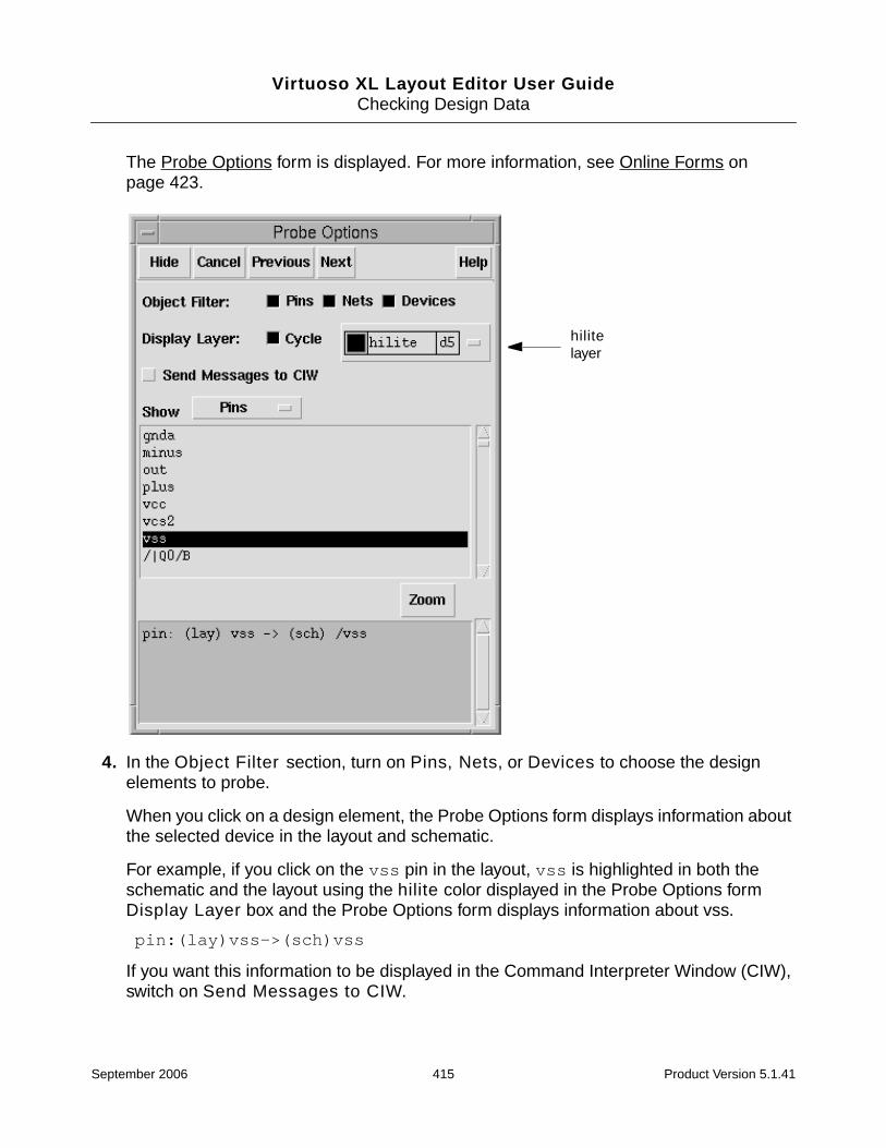
Virtuoso XL Layout Editor User GuideChecking Design Data
The Probe Options form is displayed. For more information, see Online Forms onpage 423.
4. In the Object Filter section, turn on Pins, Nets, or Devices to choose the designelements to probe.
When you click on a design element, the Probe Options form displays information aboutthe selected device in the layout and schematic.
For example, if you click on the vss pin in the layout, vss is highlighted in both theschematic and the layout using the hilite color displayed in the Probe Options formDisplay Layer box and the Probe Options form displays information about vss.
pin:(lay)vss->(sch)vss
If you want this information to be displayed in the Command Interpreter Window (CIW),switch on Send Messages to CIW.
hilitelayer
September 2006 415 Product Version 5.1.41
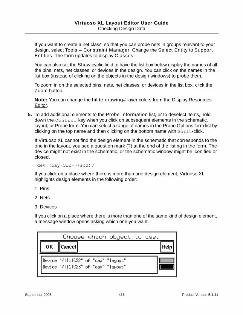
Virtuoso XL Layout Editor User GuideChecking Design Data
If you want to create a net class, so that you can probe nets in groups relevant to yourdesign, select Tools – Constraint Manager. Change the Select Entity to SupportEntities. The form updates to display Classes.
You can also set the Show cyclic field to have the list box below display the names of allthe pins, nets, net classes, or devices in the design. You can click on the names in thelist box (instead of clicking on the objects in the design windows) to probe them.
To zoom in on the selected pins, nets, net classes, or devices in the list box, click theZoom button.
Note: You can change the hilite drawing# layer colors from the Display ResourcesEditor.
5. To add additional elements to the Probe Information list, or to deselect items, holddown the Control key when you click on subsequent elements in the schematic,layout, or Probe form. You can select a range of names in the Probe Options form list byclicking on the top name and then clicking on the bottom name with Shift-click.
If Virtuoso XL cannot find the design element in the schematic that corresponds to theone in the layout, you see a question mark (?) at the end of the listing in the form. Thedevice might not exist in the schematic, or the schematic window might be iconified orclosed.
dev:(lay)Q12->(sch)?
If you click on a place where there is more than one design element, Virtuoso XLhighlights design elements in the following order:
1. Pins
2. Nets
3. Devices
If you click on a place where there is more than one of the same kind of design element,a message window opens asking which one you want.
September 2006 416 Product Version 5.1.41
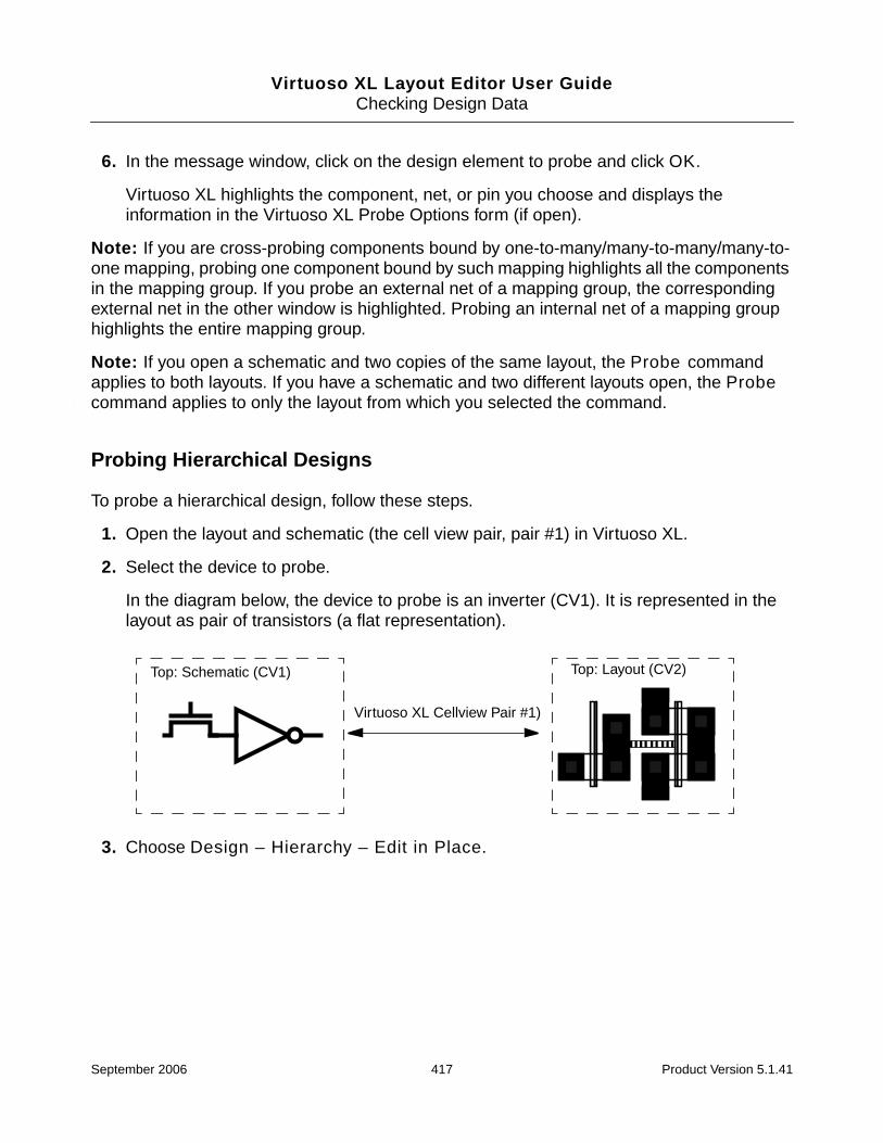
Virtuoso XL Layout Editor User GuideChecking Design Data
6. In the message window, click on the design element to probe and click OK.
Virtuoso XL highlights the component, net, or pin you choose and displays theinformation in the Virtuoso XL Probe Options form (if open).
Note: If you are cross-probing components bound by one-to-many/many-to-many/many-to-one mapping, probing one component bound by such mapping highlights all the componentsin the mapping group. If you probe an external net of a mapping group, the correspondingexternal net in the other window is highlighted. Probing an internal net of a mapping grouphighlights the entire mapping group.
Note: If you open a schematic and two copies of the same layout, the Probe commandapplies to both layouts. If you have a schematic and two different layouts open, the Probecommand applies to only the layout from which you selected the command.
Probing Hierarchical Designs
To probe a hierarchical design, follow these steps.
1. Open the layout and schematic (the cell view pair, pair #1) in Virtuoso XL.
2. Select the device to probe.
In the diagram below, the device to probe is an inverter (CV1). It is represented in thelayout as pair of transistors (a flat representation).
3. Choose Design – Hierarchy – Edit in Place.
Top: Schematic (CV1) Top: Layout (CV2)
Virtuoso XL Cellview Pair #1)
September 2006 417 Product Version 5.1.41

Virtuoso XL Layout Editor User GuideChecking Design Data
The schematic of the inverter opens (CV3 in the diagram).
If you select one of the transistors in this schematic to probe, the corresponding transistorin the layout in the level above is highlighted (CV2 in the diagram).
4. In the inverter schematic (CV3), select one of the two NMOS elements.
5. In the schematic window Tools menu, choose Design Synthesis – Layout XL to openthe layout of the inverter (CV4 in the diagram) in Virtuoso XL.
This creates another cellview pair (pair #2).
Inv: Schematic (CV3) Inv: Layout (CV4)
Virtuoso XL Cellview Pair #2)
Top: Schematic (CV1) Top: Layout (CV2)
Virtuoso XL Cellview Pair #1)
September 2006 418 Product Version 5.1.41
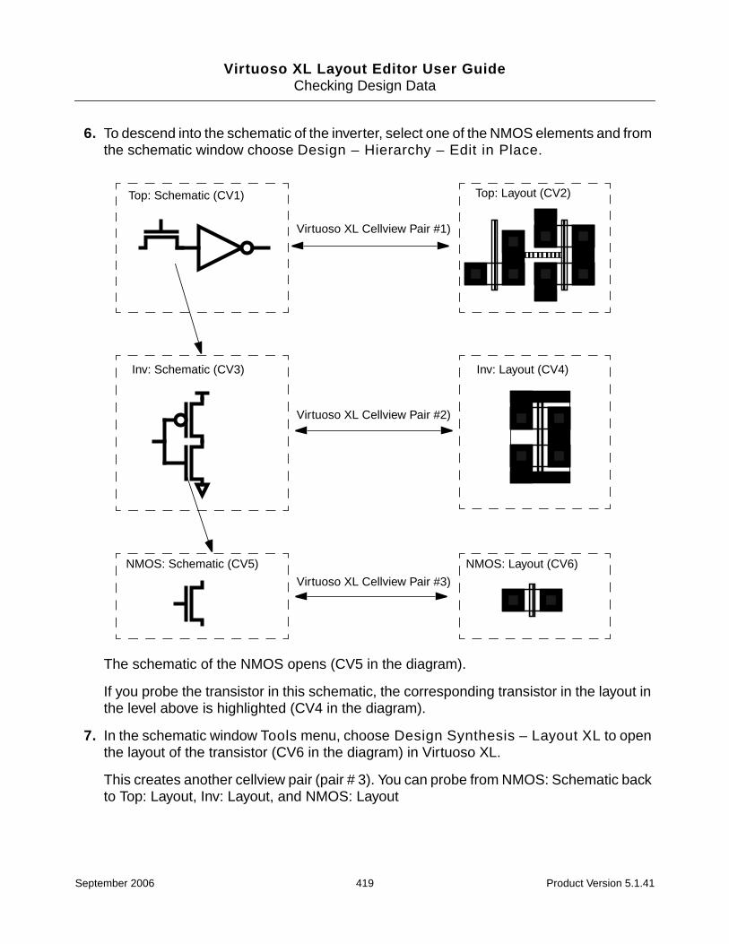
Virtuoso XL Layout Editor User GuideChecking Design Data
6. To descend into the schematic of the inverter, select one of the NMOS elements and fromthe schematic window choose Design – Hierarchy – Edit in Place.
The schematic of the NMOS opens (CV5 in the diagram).
If you probe the transistor in this schematic, the corresponding transistor in the layout inthe level above is highlighted (CV4 in the diagram).
7. In the schematic window Tools menu, choose Design Synthesis – Layout XL to openthe layout of the transistor (CV6 in the diagram) in Virtuoso XL.
This creates another cellview pair (pair # 3). You can probe from NMOS: Schematic backto Top: Layout, Inv: Layout, and NMOS: Layout
Top: Schematic (CV1) Top: Layout (CV2)
Virtuoso XL Cellview Pair #1)
Inv: Schematic (CV3) Inv: Layout (CV4)
Virtuoso XL Cellview Pair #2)
NMOS: Schematic (CV5) NMOS: Layout (CV6)
Virtuoso XL Cellview Pair #3)
September 2006 419 Product Version 5.1.41
Virtuoso XL Layout Editor User GuideChecking Design Data
Removing Probes
To remove an individual probe from the layout,
➤ Hold down the Control key and click on the probe to delete.
To remove all probes from windows,
➤ Click on an empty space in the layout window.
Exiting the Probe Command
To exit the Probe command,
➤ Click Cancel in the Virtuoso XL Probe Options form or press Escape.
Showing the Options Form
To set the Probe Options form to appear each time you use the Probe command, follow thesesteps.
1. From the CIW, choose Utilities – User Preferences.
The User Preferences form is displayed.
2. Click Options Displayed When Commands Start.
3. Click OK.
The options form opens automatically the next time you use the Probe command.
Checking Shorts and Opens
You can use the Connectivity – Check – Shorts and Opens command to check thenumber of incomplete nets, short markers, and illegal overlap markers in your design.
Tip
The command relies on extractor markers. If you have deleted these markers, youmust re-extract your design before checking for shorts and opens. For moreinformation, see “Re-Extracting a Top-Level Design” on page 299.
To check the number of shorts, opens, and illegal overlap markers
September 2006 420 Product Version 5.1.41
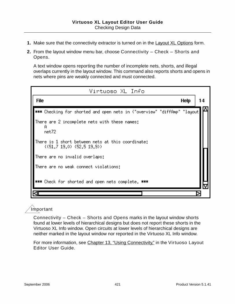
Virtuoso XL Layout Editor User GuideChecking Design Data
1. Make sure that the connectivity extractor is turned on in the Layout XL Options form.
2. From the layout window menu bar, choose Connectivity – Check – Shorts andOpens.
A text window opens reporting the number of incomplete nets, shorts, and illegaloverlaps currently in the layout window. This command also reports shorts and opens innets where pins are weakly connected and must connected.
Important
Connectivity – Check – Shorts and Opens marks in the layout window shortsfound at lower levels of hierarchical designs but does not report these shorts in theVirtuoso XL Info window. Open circuits at lower levels of hierarchical designs areneither marked in the layout window nor reported in the Virtuoso XL Info window.
For more information, see Chapter 13, “Using Connectivity,” in the Virtuoso LayoutEditor User Guide.
September 2006 421 Product Version 5.1.41
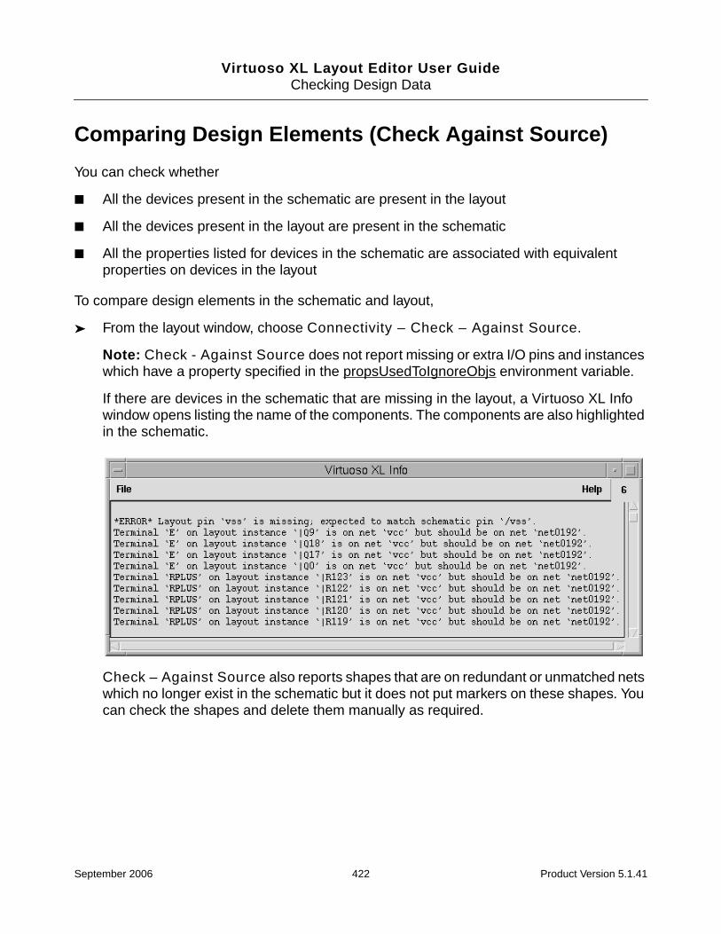
Virtuoso XL Layout Editor User GuideChecking Design Data
Comparing Design Elements (Check Against Source)
You can check whether
■ All the devices present in the schematic are present in the layout
■ All the devices present in the layout are present in the schematic
■ All the properties listed for devices in the schematic are associated with equivalentproperties on devices in the layout
To compare design elements in the schematic and layout,
➤ From the layout window, choose Connectivity – Check – Against Source.
Note: Check - Against Source does not report missing or extra I/O pins and instanceswhich have a property specified in the propsUsedToIgnoreObjs environment variable.
If there are devices in the schematic that are missing in the layout, a Virtuoso XL Infowindow opens listing the name of the components. The components are also highlightedin the schematic.
Check – Against Source also reports shapes that are on redundant or unmatched netswhich no longer exist in the schematic but it does not put markers on these shapes. Youcan check the shapes and delete them manually as required.
September 2006 422 Product Version 5.1.41

Virtuoso XL Layout Editor User GuideChecking Design Data
If a device that is not in the schematic is present in the layout, it appears with a blinkingmarker.
If a device parameter in the layout is different from the corresponding parameter in theschematic, a text window appears and lists the device names and properties (unless thedevice is ignored).
To save the information in an ASCII file or close the Virtuoso XL Info window,
➤ Use the commands on the File menu.
Using CDF Callbacks with Check Against Source
Check Against Source uses the schematic list of parameters, but the layout value of thewidth (for folding), sParam (for sfactor), and mfactor=1 and sfactor=1 to verify the listof parameters. The total width/sParam is compared before applying the callback, all otherparameters are compared with the corresponding master after applying the callback.
Online Forms
Probe Options
Object Filter specifies the objects highlighted by the probe command.
Pins specifies that the probe command highlights pins.
Nets specifies that the probe command highlights nets.
Devices specifies that the probe command highlights devices.
Display Layer shows which of the hilite drawing # layers is to be used in the next probedrawn.
npn
npn np
n
npn
npn
npn
npn
in
out
Marker
September 2006 423 Product Version 5.1.41
Virtuoso XL Layout Editor User GuideChecking Design Data
Cycle, when turned on, changes the hilite layer to the next color when a new object isprobed. When Cycle is not turned on, the hilite layer does not change to the next color eachtime a new object is probed.
Send Messages to CIW, when turned on, sends the information about the objects probedto the CIW (as well as displaying it in the box at the bottom of the form, when the form is open).
Show displays in the list box the names of the nets, pins, net classes, or devices in the design(depending on which category you select in the cyclic field). When you click on one or moreitems in the list box, the items are probed (highlighted) in the schematic and in the layout andthe name, window, and equivalency information about each item is shown in the display box.When you remove a probe, that information disappears from the display box.
Zoom to the bounding box of the current probing objects based on the probe type.
September 2006 424 Product Version 5.1.41

Virtuoso XL Layout Editor User Guide
12Updating Design Data
This chapter explains how to use the Virtuoso® XL Layout Editor to make design changes andupdate your design as you progress.
It contains information on the following areas.
■ Updating Components and Nets (Engineering Change Order Mode) on page 426
■ Updating Layout Parameters on page 432
■ Updating Schematic Parameters on page 434
■ Updating Device Correspondence on page 436
■ Creating Device Correspondence on page 444
■ Updating the Connectivity Reference on page 449
■ Changing the Device (Instance) View on page 450
For information on Virtuoso XL forms, see “Online Forms” on page 451.
September 2006 425 Product Version 5.1.41
Virtuoso XL Layout Editor User GuideUpdating Design Data
Updating Components and Nets (Engineering ChangeOrder Mode)
Virtuoso XL can automatically update the layout to take account of any devices, pins, orconnectivity changes you have added to the schematic. This operation is sometimes knownas Engineering Change Order (ECO) mode.
While Gen From Source deletes any existing components in the layout view andregenerates everything from scratch, Update Components And Nets updates only thecomponents that have changed; adding new devices and pins, deleting (or marking) olddevices and pins, and updating masters and connectivity to match that of the schematic.
Tip
Activate Connectivity – Show Incomplete Nets before you update componentsand nets. This lets you verify that the connectivity you want is made.
To update the components and nets in a layout with changes made to a schematic,
1. In the schematic window select Check – Current Cellview.
The schematic editor extracts the connectivity of the design and reports the results in aSchematic Check information window.
2. From the layout window, choose Connectivity – Update – Components and Nets.
Virtuoso XL checks the components and nets in the schematic against the ones in thelayout.
If the schematic has changed, you see a dialog box indicating that schematic extractionis needed to continue. Virtuoso XL issues a message to the CIW indicating the cellviewsthat are out of date.
❑ If you click OK in the dialog box, Virtuoso XL performs a hierarchical extraction onthe schematic and all of its reference libraries. However, the extracted cellviews arenot automatically saved.
❑ If you want a different extraction behavior, click Cancel in the dialog box and selectthe Check – Hierarchy command in the schematic window. Click OK to run theCheck Hierarchy command.
If there are no differences, a message appears in the Command Interpreter Window(CIW) saying that the check has been completed successfully.
If there are differences, they are reported in the CIW.
September 2006 426 Product Version 5.1.41
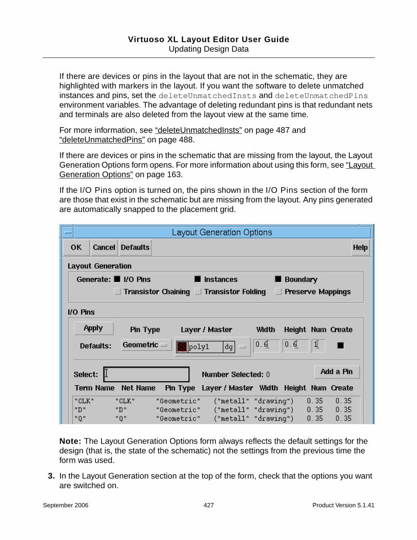
Virtuoso XL Layout Editor User GuideUpdating Design Data
If there are devices or pins in the layout that are not in the schematic, they arehighlighted with markers in the layout. If you want the software to delete unmatchedinstances and pins, set the deleteUnmatchedInsts and deleteUnmatchedPinsenvironment variables. The advantage of deleting redundant pins is that redundant netsand terminals are also deleted from the layout view at the same time.
For more information, see “deleteUnmatchedInsts” on page 487 and“deleteUnmatchedPins” on page 488.
If there are devices or pins in the schematic that are missing from the layout, the LayoutGeneration Options form opens. For more information about using this form, see “LayoutGeneration Options” on page 163.
If the I/O Pins option is turned on, the pins shown in the I/O Pins section of the formare those that exist in the schematic but are missing from the layout. Any pins generatedare automatically snapped to the placement grid.
Note: The Layout Generation Options form always reflects the default settings for thedesign (that is, the state of the schematic) not the settings from the previous time theform was used.
3. In the Layout Generation section at the top of the form, check that the options you wantare switched on.
September 2006 427 Product Version 5.1.41

Virtuoso XL Layout Editor User GuideUpdating Design Data
❑ Transistor chaining and transistor folding
Turn on the Transistor Chaining option to recreate the abutment into chains ofMOS transistors or fingers of folded MOS transistors that were unabutted since youcreated them using the Design – Gen From Source command.
Turn on the Transistor Folding option to recreate and fold MOS transistors thatwere unfolded or all fingers of which were deleted since you created them with theDesign – Gen From Source command.
If you switch on these options, the Update Components and Nets commandchains and folds only new devices. New chains are not attached to existing chains.Devices that were chained prior to running the command are not moved from theirexisting positions.
If the Transistor Chaining and Transistor Folding options are switched off, andyou have deleted all the fingers of a folded transistor, Update Components andNets generates a single device. If you have deleted some of the fingers of a foldeddevice, it creates markers only if fingers in a numbered sequence are missing;otherwise it does nothing about missing fingers of folded transistors.
❑ To preserve existing many-to-many mapping of devices between the connectivitysource and the layout, turn on Preserve Mappings.
Note: This function does not report missing devices or shapes within a mappedgroup.
4. For each pin you want to add, click Add a Pin.
An empty pin row opens. Enter the Net Name, Pin Type, Layer/Master, Width,Height, and specify the number of these pins that you want.
5. Set the Pin Label Shape for all pins.
a. Set Label to generate labels for each pin on the text dg layer-purpose pair.
Note: Virtuoso XL does not generate labels for symbolic pins.
b. Set Text Display to generate text for each pin on the text dg layer-purpose pair.
To view the text, set the Pin Names option on in the Display Options form.
c. Set None to prevent label generation for pins.
6. To set the style of the pin labels, click the Display Pin Name Option button.
The Display Pin Name Option form is displayed.
7. Choose the options you want from the Set Pin Label Text Style form and click OK.
September 2006 428 Product Version 5.1.41

Virtuoso XL Layout Editor User GuideUpdating Design Data
8. If you want Virtuoso XL to draw a boundary, follow the steps below.
a. Choose the layer you want to use for the boundary.
b. In the Shape field, choose Rectangle or Polygon.
❍ Specify the dimensions of a rectangular boundary using the Utilization %,Aspect Ratio (W/H), Boundary Width, and Boundary Height options.
Use the Left and Bottom fields to specify the origin of the boundary. Type thex coordinate in the Left field and the y coordinate in the Bottom field.
❍ Specify the dimensions of a polygonal boundary by entering the X and Ycoordinates of each angle of the polygon in the Points type-in field in thefollowing format. For example, for a rectangle: (0 0) (0 10) (10 8) (8 0) (0 0).
When you move the cursor in the layout window, the X and Y coordinates of thelocation of the cursor are displayed in the Status Line at the top of the layout window.
September 2006 429 Product Version 5.1.41

Virtuoso XL Layout Editor User GuideUpdating Design Data
9. In the Template File section, to load a template file, (an ASCII file containing theinformation entered in this form in a previous session and saved to a file) follow thesesteps.
a. Select the Load Template File for Layout Generation option.
b. Click the Browse button and the Open File form is displayed.
c. Click on the directories in the left list box to descend into your file hierarchy until youreach the name of the template file to use.
d. Click on the name of the template file in the right list box to enter it in the Name field.
The left and right arrows at the right side of the form let you go up and down in thefile hierarchy.
e. Click OK in the Open File form.
The values in the template file are loaded into the Layout Generation Options formand are used during the design session.
You can set an environment variable called templateFileName to always load thename of a template you specify as the value of the variable.
10. To save the information you enter in the Layout Generation Options form from thecellview to a template file (an ASCII file) to use in a later session., follow these steps.
a. Select Design – Save To Template.
The Template File form is displayed.
b. Turn on the Boundary and I/O Pins options
c. In the Template file name field type in a template file name.
d. Click OK.
The data you selected is saved in the template file.
11. Click OK.
September 2006 430 Product Version 5.1.41
Virtuoso XL Layout Editor User GuideUpdating Design Data
Virtuoso XL puts any missing pins and components below the design boundary andupdates their connectivity.
If the schematic master has changed, Layout XL updates the layout master accordingly,as long as the updateReplacesMasters is set to t.
If there is a schematic instance with a master which does not exist on the layout side,Virtuoso XL descends into the schematic hierarchy to try to generate the instancescontained inside.
Note: Permuted pins are not preserved by the Update Components and Netscommand. If any component in the design needs to be updated, the command resets thepermutation status of all of the cells to that originally stored in the schematic.
If a device that has been folded into fingers is missing in the layout, Virtuoso XL recreatesthe device.
If one or more fingers of a device that has been folded into fingers is missing in the layout,the CIW displays a warning that the fingers corresponding to the schematic instance aremissing, but it does not recreate the fingers.
If a parameter regulating the width of the fingers of a folded device has changed in theschematic, it is not changed in the layout by this command. Use the Connectivity –Update – Layout Parameters command to implement parameter changes in theschematic that affect physical implementations in the layout.
Note: When Update Components and Nets is not able to find a valid view as specifiedin the stopList and the layout was not placed as a result, the following error messageappears.
w *WARNING* Could not find master cellView ‘test,nmos_2v,layout compacted
symbolic’.
\w *WARNING* Could not find master cellView ‘test,nmos_2v,layout compacted
symbolic’.
\w *WARNING* There were errors during Update Components and Nets.
\w *WARNING* Run Check Against Source for details.
Connectivity – Update – Components and Nets preserves many-to-one and many-to-many mapping between the connectivity source and the layout cellview.
Note: You can use the Edit – Undo command to undo any changes that you made with theConnectivity – Update – Components and Nets command.
September 2006 431 Product Version 5.1.41

Virtuoso XL Layout Editor User GuideUpdating Design Data
Updating Layout Parameters
To update the parameters of instances in the layout to match those in the schematic, followthese steps.
1. From the layout window, choose Connectivity – Update – Layout Parameters.
If you preselected instances, Virtuoso XL checks parameters of those instances in theschematic against their parameters in the layout and updates the layout parameterswhen it finds differences.
If you did not preselect instances, the CIW and the layout window prompt you to selectdevices whose parameters you want to update.
If there is no schematic referenced by the layout, the Define Connectivity Reference formis displayed. If there is currently a connectivity reference for the layout, that informationis displayed. You can change the connectivity reference in this form.
Note: Connectivity-Update – Layout Parameters will update folded devices if theUpdate Parameter option is turned on in the XL Options form. Check the size of foldeddevices manually to avoid overriding the specified size.
2. Click OK on the Define Connectivity Reference form.
3. Select a device in the layout or schematic window.
You can use Shift-click to select more than one instance. Virtuoso XL highlights theinstance in the layout and the schematic window.
4. Move the cursor to the layout window and press Return.
Virtuoso XL checks parameters of those instances in the schematic against theirparameters in the layout and updates the layout parameters when it finds differences.
5. To see a list of the layout devices, move the cursor to the layout window and press F3.
September 2006 432 Product Version 5.1.41
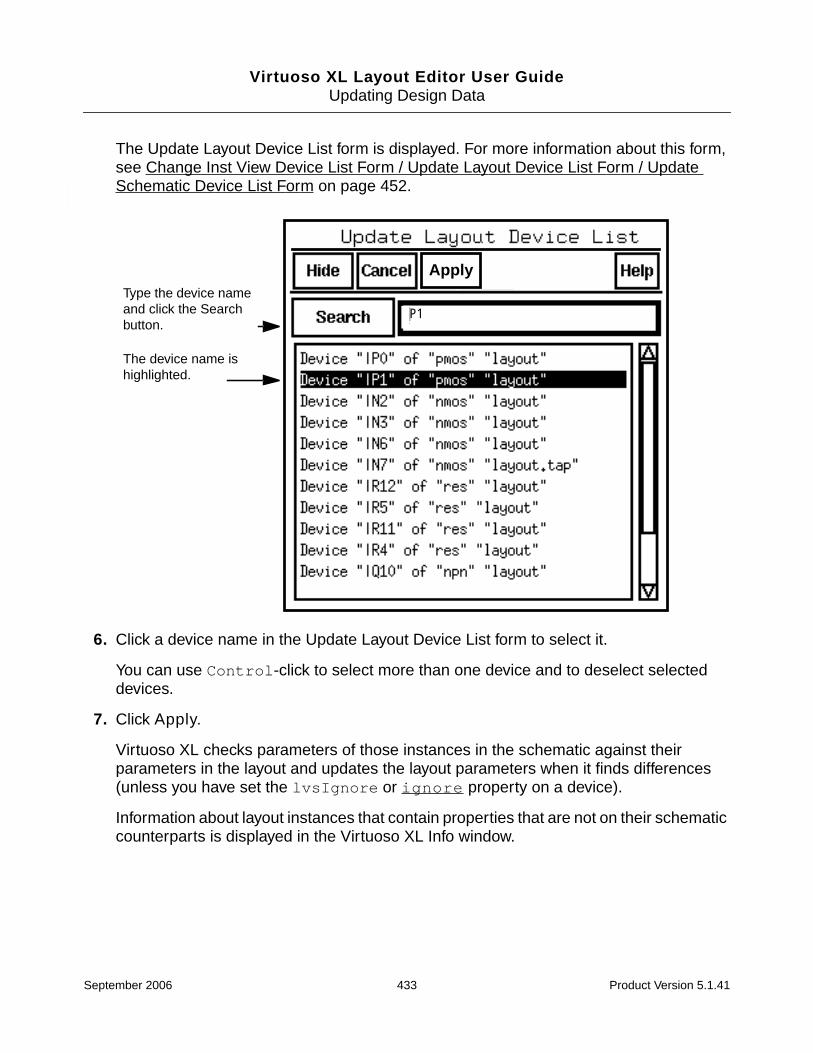
Virtuoso XL Layout Editor User GuideUpdating Design Data
The Update Layout Device List form is displayed. For more information about this form,see Change Inst View Device List Form / Update Layout Device List Form / UpdateSchematic Device List Form on page 452.
6. Click a device name in the Update Layout Device List form to select it.
You can use Control-click to select more than one device and to deselect selecteddevices.
7. Click Apply.
Virtuoso XL checks parameters of those instances in the schematic against theirparameters in the layout and updates the layout parameters when it finds differences(unless you have set the lvsIgnore or ignore property on a device).
Information about layout instances that contain properties that are not on their schematiccounterparts is displayed in the Virtuoso XL Info window.
Type the device nameand click the Searchbutton.
The device name ishighlighted.
|P1
Apply
September 2006 433 Product Version 5.1.41

Virtuoso XL Layout Editor User GuideUpdating Design Data
When Virtuoso XL checks or updates any instance, a Virtuoso XL Info window reportsthe updates that were made.
If updating parameters results in a change in the layout, Virtuoso XL updates theconnectivity and indicates any shorts with markers.
If you have CDF callbacks Update Layout Parameter applies the callback first thenapplies all differing parameters on the source instance.
Note: Update Components and Nets does not update split transistors if the sizes ofthe resulting transistors are different because such transistors may be the result ofmanual splitting. If the layout figure selected for update is a transistor that has beenfolded, Virtuoso XL displays a message box that says that it is not updating theparameters.
8. Press Escape to exit the command.
Note: If you are using inherited connections in your design to assign more than one value toa global net, remember that the netSet properties on schematic instances, which specifythe new value of a global signal, are not copied over with the instance from the schematic tothe layout when you use the Gen From Source, Pick from Schematic, or Update LayoutParameters commands.
For more information, see the Inherited Connections Flow Guide.
Updating Schematic Parameters
To update the parameters of devices in the schematic to match those in the layout, followthese steps.
Note: You must have the schematic window open in edit mode to use this command.
1. From the layout window, choose Connectivity – Update – Schematic Parameters.
September 2006 434 Product Version 5.1.41

Virtuoso XL Layout Editor User GuideUpdating Design Data
If you preselected instances, Virtuoso XL checks parameters of the selected instancesin the schematic against the parameters of the corresponding instances in the layout andupdates the schematic parameters when it finds differences. A Virtuoso XL Info windowreports the change.
If you did not preselect instances, the CIW and layout window prompt you to selectinstances whose parameters you want to update.
2. Select a device in either the layout or schematic window.
You can use Shift-click to select more than one device. Virtuoso XL highlights thedevice in the window.
3. Move the cursor to the layout window and press Return.
Virtuoso XL checks parameters of those instances in the schematic against theirparameters in the layout and updates the schematic parameters when it finds differences(unless you have set the lvsIgnore or ignore property on a device).
4. To see a list of the layout devices, move the cursor to the layout window and press F3.
The Update Schematic Device List form is displayed. For more information about thisform, see Change Inst View Device List Form / Update Layout Device List Form / UpdateSchematic Device List Form on page 452.
5. Select a device name in the Update Schematic Device List form.
You can use Control-click to select more than one device.
6. Click Apply.
The device name ishighlighted.
Apply
Type the net name andclickthe Search button.
September 2006 435 Product Version 5.1.41

Virtuoso XL Layout Editor User GuideUpdating Design Data
Virtuoso XL checks parameters of those instances in the schematic against theirparameters in the layout and updates the schematic parameters when it findsdifferences.
If you have CDF callbacks Update Layout Parameter applies the callback first thenapplies all differing parameters on the source instance.
When Virtuoso XL checks or updates any instance, a Virtuoso XL Info window reportsthe updates that were made.
7. Press Escape to exit the command.
Updating Device Correspondence
You can use the Connectivity – Update – Device Correspondence command to maintainconnectivity in a layout when you want to
■ Apply the connectivity from a symbol in the default schematic to a device in the layout
■ Apply the connectivity from a group of symbols in the default schematic to a device orgroup of devices in the layout (many-to-many and many-to-one mapping)
■ Modifying Many-to-Many or Many-to-One Mapping Between Components
■ Deleting Many-to-Many or Many-to-One Mapping Between Components
■ Apply the connectivity from a single device in the schematic to multiple devices in thelayout.
■ Apply connectivity to devices in a layout from a relevant schematic if you did not useVirtuoso XL to generate your layout
‘(-0.125 0.125)’
September 2006 436 Product Version 5.1.41
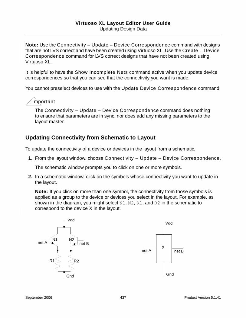
Virtuoso XL Layout Editor User GuideUpdating Design Data
Note: Use the Connectivity – Update – Device Correspondence command with designsthat are not LVS correct and have been created using Virtuoso XL. Use the Create – DeviceCorrespondence command for LVS correct designs that have not been created usingVirtuoso XL.
It is helpful to have the Show Incomplete Nets command active when you update devicecorrespondences so that you can see that the connectivity you want is made.
You cannot preselect devices to use with the Update Device Correspondence command.
Important
The Connectivity – Update – Device Correspondence command does nothingto ensure that parameters are in sync, nor does add any missing parameters to thelayout master.
Updating Connectivity from Schematic to Layout
To update the connectivity of a device or devices in the layout from a schematic,
1. From the layout window, choose Connectivity – Update – Device Correspondence.
The schematic window prompts you to click on one or more symbols.
2. In a schematic window, click on the symbols whose connectivity you want to update inthe layout.
Note: If you click on more than one symbol, the connectivity from those symbols isapplied as a group to the device or devices you select in the layout. For example, asshown in the diagram, you might select N1, N2, R1, and R2 in the schematic tocorrespond to the device X in the layout.
Vdd
Gnd
N1net A net B
N2
R1
Vdd
Gnd
net A net BX
R2
September 2006 437 Product Version 5.1.41

Virtuoso XL Layout Editor User GuideUpdating Design Data
3. With the cursor in the schematic window, press Return.
The layout window prompts you to select one or more corresponding objects in the layoutwindow.
4. In the layout window, click on the object or objects to associate with the symbol.
Important
Device correspondence will not list mismatched instances that have the same nameas an existing instance. Rename the instance so that no name space overlap exists.
5. With the cursor in the layout window, press Return.
Important
The correspondence is defined only when you press Return.
A message such as this one appears in the CIW saying that the connection has beenmade:
Virtuoso XL: Instance ’I1’ in cellView ’overview amp1 layout’ is renamed’|R21’.
If the Show Incomplete Nets command is active, flight lines show that the connectionhas been made. If the connection cannot be made, a message box identifies theproblem.
6. To cancel the command, press Escape.
Note: If you have set the lvsIgnore or ignore property on a device and then try tomake that device correspond to another device, Virtuoso XL opens a dialog box askingyou to verify the removal of the ignore or lvsIgnore property.
If you click OK, Virtuoso XL removes the property and sets the two devices tocorrespond. If you click Cancel, Virtuoso XL does not set the devices to correspond.
One-to-Many Assignment with Update Device Correspondence
You can also map a single device in the schematic to multiple devices in the layout using theUpdate – Device Correspondence command. You might want to do this if you need to mapa device in the schematic to a flattened layout instance.
Note: You can map One-to-Many devices only between cellview pairs; that is, between theschematic and layout that correspond to each other and are at the same hierarchical level.For example, you cannot map an instance in the one to multiple instances accessed througha descend edit in the other.
September 2006 438 Product Version 5.1.41

Virtuoso XL Layout Editor User GuideUpdating Design Data
To map an instance in the schematic to multiple instances in the layout, follow these steps.
1. From the layout Connectivity menu, choose Update – Device Correspondence.
The schematic window and the CIW prompt you to choose one or more instances fromthe schematic.
2. Select a component from the schematic and press Return in the schematic window.
The layout window and the CIW prompt you to choose one or more instances from thelayout window.
Preselected components are considered part of the selection unless you specificallydeselect them.
For example, in the diagram below, you can select the resistor A from the schematic tobe mapped to the resistors R21, R22, and R6 in the layout.
3. Select the instances in the layout window and press Return.
Important
The correspondence is defined only when you press Return.
Virtuoso XL checks your selection for connectivity. If the number of external nets in thelayout selection is less than the number of external nets in the schematic selection, themapping is not set.
If the number of external nets in the layout selection is the same as or greater than thenumber of external nets in the schematic selection, a dialog box shows the nets that donot match and asks if you want to use Assign Nets to assign the nets of the layoutcomponents to nets corresponding to those in the schematic.
a. Choose Yes.
net2
net2
R21R = 8k
Schematic Layout (showing incomplete nets)
A
net1
r = 5kr = 2kr = 1k
net1
R22
R6
September 2006 439 Product Version 5.1.41
Virtuoso XL Layout Editor User GuideUpdating Design Data
The Assign Nets function highlights all unmatched nets from the schematic andlayout.
The CIW and layout window prompt you to select a pin within an instance to add toa net.
You can press F3 to see a list of the nets in the design.
b. Click on a pin in one of the instances in the layout that you want to correspond to theinstance in the schematic.
The CIW and layout window prompt you to select a net to add the pin to.
c. Click on a net in the schematic or a path in the layout.
Assign Nets connects the pin to the net.
d. When you have finished assigning nets, click Cancel on the Assign Nets Form orpress Escape to cancel the Assign Nets command.
The Assign Nets command is not canceled and the prompt to select a pin does notdisappear until all the unassigned pins are connected to nets.
The Device Correspondence command checks to see that the components are all inone group.
❑ If they are all in the same group, Virtuoso XL leaves them in the group and the CIWdisplays a message that mapping has been successful.
❑ If only some of them are in a group, Virtuoso XL puts the rest in the group and theCIW displays a message that mapping has been successful.
❑ If none of them is in a group, Virtuoso XL creates a new group and puts them all in.The CIW displays a message that mapping has been successful.
❑ If they are in different groups, the CIW displays a message that mapping cannot beset because they are in different groups.
If Virtuoso XL needs to create a group, the group is called lxMTM. A property calledlxMTM is created and attached to the group in the layout. The property value is the nameof all the selected components from the schematic. All the components selected from thelayout are the members of the group.
Note: More than one group in a layout cellview can be named lxMTM. But a componentcan belong to only one such group.
You can repeat this process to assign all the elements in the “many” group to nets.
4. Press Escape to cancel the Device Correspondence command.
September 2006 440 Product Version 5.1.41

Virtuoso XL Layout Editor User GuideUpdating Design Data
Using Many-to-Many or Many-to-One Mapping
You can map multiple devices in the schematic to one or more devices (including shapes) inthe layout by using the Update Components and Nets command. You might want to do thisif you need to map a symbol or symbols in the schematic to a flattened layout instance.
Note: You can map many-to-many devices only between cellview pairs; that is, between theschematic and layout that correspond to each other and are on the same hierarchical level.For example, you cannot map an instance in the one to multiple instances accessed througha descend edit in the other.
To map multiple symbols in the schematic to one or more instances in the layout, follow thesesteps.
1. From the layout Connectivity menu, choose Update – Device Correspondence.
The schematic window and the CIW prompt you to choose one or more instances fromthe schematic.
2. Select the components to be mapped from the schematic and press Return in theschematic window.
The layout window and the CIW prompt you to choose one or more instances from thelayout window.
For example, in the diagram below, you could select the resistors R1 and R2, NMOStransistors N1 and N2, and devices X and Y from the schematic to be mapped to thedevices L and M in the layout (many-to-many) or the block MISC in the layout (many-to-one).
The number of external nets in the selected group in the schematic (in the example, netsA, B, and C) must be the same as the number of external nets in the selected group inthe layout.
September 2006 441 Product Version 5.1.41

Virtuoso XL Layout Editor User GuideUpdating Design Data
The software lets you ignore global nets, such as Vdd and Gnd, in the schematicbecause global nets are not indicated on many schematics. But if a schematic has globalnets, they must be shown in the layout.
3. Select the instances in the layout window and press Return.
Important
The correspondence is defined only when you press Return.
If you are assigning many-to-many, the Device Correspondence command checks tosee that the layout components are all in one group.
❑ If they are all in the same group, Virtuoso XL leaves them in the group and the CIWdisplays a message that mapping has been successful.
❑ If only some of them are in a group, Virtuoso XL puts the rest in the group and theCIW displays a message that mapping has been successful.
❑ If none of them is in a group, Virtuoso XL creates a new group and puts them all in.The CIW displays a message that mapping has been successful.
❑ If they are in different groups, the CIW displays a message that mapping cannot beset because they are in different groups.
4. If Virtuoso XL needs to create a group, the group is called lxMTM. A property calledlxMTM is created and attached to the group in the layout. The property value is the name
Vdd
N1net A net B
N2
R1 R2
Vdd
Gnd
net A
X
YGnd
net1 net2
net3
net C
M
L
net C
net B
Vdd
Gnd
net A
MISC
net C
net B
Schematic Layout (Many-to-Many) Layout (Many-to-One)
September 2006 442 Product Version 5.1.41

Virtuoso XL Layout Editor User GuideUpdating Design Data
of all the selected components from the schematic. All the components selected from thelayout are the members of the group.
Note: More than one group in a layout cellview can be named lxMTM. But a componentcan belong to only one such group.
After the components are checked, the Device Correspondence command creates thenew group.
Modifying Many-to-Many or Many-to-One Mapping between Components
To modify a mapping between components, follow these steps.
1. From the layout window Connectivity menu, choose Update – DeviceCorrespondence.
The layout window and the CIW prompt you to select one or more instances from theschematic window.
2. In the schematic, select one of the components in the group that you want to modify.
All the components in the group are highlighted.
3. To delete some schematic components from or add others to the group, use Control-click to select those components to add and Shift-click to deselect the components tobe deleted.
4. Press Return in the schematic window.
The layout window and the CIW prompt you to choose one or more instances from thelayout window.
5. To delete some layout components from or add others to the group, use Control-clickto select those components to add and Shift-click to deselect the components to bedeleted.
6. Press Return in the layout window.
The new mapping is checked and, if found acceptable, created.
Deleting Many-to-Many or Many-to-One Mapping between Components
To delete a mapping between components, use the Update – Device Correspondencecommand to set a one-to-one mapping between the components.
September 2006 443 Product Version 5.1.41

Virtuoso XL Layout Editor User GuideUpdating Design Data
To delete a many-to-many (or many-to-one) mapping between components, follow thesesteps.
1. From the layout window Connectivity menu, choose Update – DeviceCorrespondence.
The layout window and the CIW prompt you to select one or more instances from theschematic window.
2. In the schematic, select one of the components in the group whose mapping you wantto delete.
All the components in the group are highlighted.
3. Use Shift-click to deselect all the components except one.
4. Press Return in the schematic window.
The layout window and the CIW prompt you to choose one or more instances from thelayout window.
5. Use Shift-click to deselect the components to be deleted except the one you want tomap to the schematic component.
6. Press Return in the layout window.
The many-to-many (or many-to-one) mappings are deleted.
Creating Device Correspondence
For layout designs that have not been created using Virtuoso XL, or to bind an existing layoutto another schematic, use the Create – Device Correspondence command to setcorrespondence between a schematic and layout.
The Create – Device Correspondence command
■ Takes an LVS-correct layout design and migrates it into Virtuoso XL.
■ Updates the layout instances’ and nets’ naming convention to the Virtuoso XL namingconventions so that legacy layouts can be reused in Virtuoso XL.
■ Enables connectivity-driven layout editing.
Needed Mode
Needed mode supports the following;
September 2006 444 Product Version 5.1.41

Virtuoso XL Layout Editor User GuideUpdating Design Data
■ Enforce master match.
■ Check connectivity once match is enforced.
■ mfactor and sfactor.
Prerequisites for the Needed mode are as follows;
■ All selected instances must have the same master.
❑ pins/instance in schematic must be mapped to a pin/instance in the layout.
To create device correspondence using the Needed mode;
1. Select Create – Device Correspondence.
2. The Create Device Correspondence form is displayed.
September 2006 445 Product Version 5.1.41
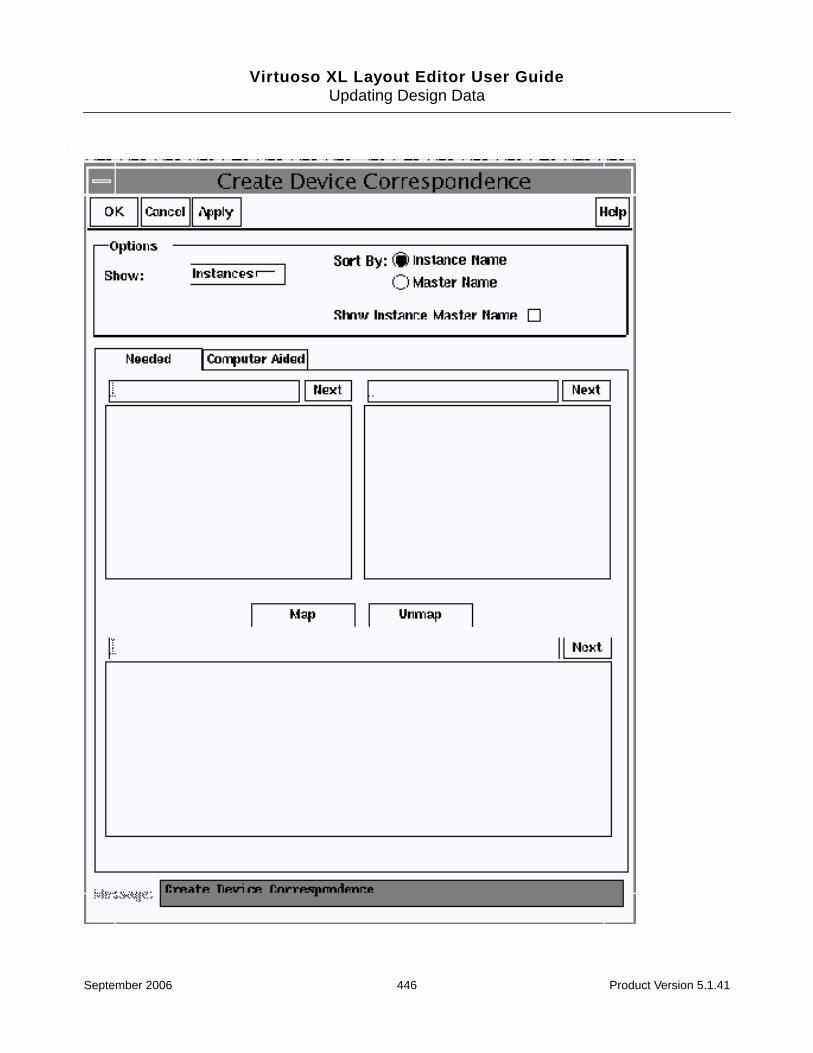
Virtuoso XL Layout Editor User GuideUpdating Design Data
September 2006 446 Product Version 5.1.41

Virtuoso XL Layout Editor User GuideUpdating Design Data
1. Leave the Show option to Instances. If you want to display the pins change the Showoption to Pins.
2. By default the mode is set the Needed.
3. Change the option to Show Instance Master Name and the library, cell, and viewnames are displayed in the list boxes.
Use the text field to highlight a particular device or set of devices. For example P* willhighlight the devices starting with “P”.
4. Click on a device in the left list box. Only one instance or pin can be selected.
The left list box lists the schematic instances and pins.
The Message field prompts you to select layout objects.
5. Click on a corresponding layout instances or pin in the right list box. Multiple instancescan be selected. If multiple instances are selected, they must all be in series or parallel.Multiple selection is only permitted if the selected schematic symbol has a sfactor ora hierarchical mfactor.
The Message field prompts you to press map or select more layouts.
Note: If you selected a NMOS instance in the schematic list box, and a PMOS instancein the layout list box then a Virtuoso XL dialog box appears. The dialog box indicates thatyou cannot map a NMOS device to a PMOS device and that you must make anotherselection.
The Message field at the bottom of the XL Create Device Correspondence form tells youthat you must adjust connectivity or layout selection.
6. To create device correspondence select the Map option. Once the instances aremapped the instance names and the names of the nets attached to the layout instancesmare changed according the Virtuoso XL naming convention.
The list box updates showing the instances/pins that are mapped.
7. To unmap mapped objects, select the mapped objects and select Unmap.
The objects are unmapped and placed in the schematic and layout list boxes.
8. Click Apply.
The matches are removed from the map list box.
The mapped instances are changed to the Virtuoso XL naming convention only whenyou click Apply or OK. Until then the information is merely visual in the form. You cancross-select, but no names are changed.
September 2006 447 Product Version 5.1.41

Virtuoso XL Layout Editor User GuideUpdating Design Data
Computer Aided Mode
Computer Aided mode supports the following;
■ Same check as Needed mode with additional LVS mappings
■ Requires that all pins are mapped first then instances.
■ Needs information from the user. The more information that you add to the form thebetter match you will have.
■ Correspondence is set from the pins.
To create device correspondence using the Computer Aided mode,
1. Select Create – Device Correspondence.
2. Change the mode to Computer Aided.
The Sort By option and Show Instance Master Name is greyed out because theseoptions only apply to instances.
The Message field asks you to create correspondence for all pins.
3. Change the Show option to Pins.
Whenever there are unmatched pins in both the connectivity source and in the layout thePins option is displayed in the Show cyclic field.
4. Select pins in the schematic and the corresponding pins in the layout list box.
5. Select Map to map the pins.
6. Once all of the pins are mapped change the Show option to Instances.
7. Turn on the Show Instance Master Name option to view the library, cell, and viewnames.
8. A partial LVS algorithm will find possible mappings and will list them in the lower-left listbox. If the mappings are correct, the mappings can be mapped using the “>” button.
Mappings can also be performed manually as in Needed mode.
For every map/unmap operation, device correspondence incrementally searches for newproposed LVS matches. The more mappings are realized, the incremental LVS algorithmwill recognize the connectivity and will propose more matches.
Note: If a large number of instances are unmapped or the number of different mastersis small, the LVS algorithm might return old mappings. In this case, manual mapping fromthe top boxes will provide the algorithm with new data and the algorithm will start
September 2006 448 Product Version 5.1.41

Virtuoso XL Layout Editor User GuideUpdating Design Data
converging towards finding correct mappings. You are responsible for validating thepossible mappings proposed by the algorithm.
Updating the Connectivity Reference
In Virtuoso XL, the default schematic is the schematic with the same cellview name as thelayout.
You can change this setup so that you can update your layout using a schematic different fromthe default schematic by following these steps.
1. Choose Connectivity – Update – Source.
The Define Connectivity Reference form is displayed.
2. Choose Schematic as the connectivity source type.
3. Do one of the following:
❑ Type the name of the library, cell, and view of the device to update in Library, Cell,and View fields.
❑ Click Browse to see the cells available in the Library Browser, and click on a cellname in the Library Browser.
❑ Click Sel by Cursor and then click on an open schematic.
4. Click Update layout cellviews hierarchically to update the library setting for any forany lower-level cellviews in a hierarchical cellview, except
September 2006 449 Product Version 5.1.41
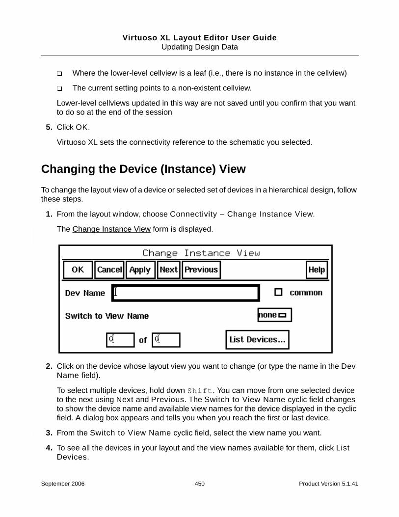
Virtuoso XL Layout Editor User GuideUpdating Design Data
❑ Where the lower-level cellview is a leaf (i.e., there is no instance in the cellview)
❑ The current setting points to a non-existent cellview.
Lower-level cellviews updated in this way are not saved until you confirm that you wantto do so at the end of the session
5. Click OK.
Virtuoso XL sets the connectivity reference to the schematic you selected.
Changing the Device (Instance) View
To change the layout view of a device or selected set of devices in a hierarchical design, followthese steps.
1. From the layout window, choose Connectivity – Change Instance View.
The Change Instance View form is displayed.
2. Click on the device whose layout view you want to change (or type the name in the DevName field).
To select multiple devices, hold down Shift. You can move from one selected deviceto the next using Next and Previous. The Switch to View Name cyclic field changesto show the device name and available view names for the device displayed in the cyclicfield. A dialog box appears and tells you when you reach the first or last device.
3. From the Switch to View Name cyclic field, select the view name you want.
4. To see all the devices in your layout and the view names available for them, click ListDevices.
September 2006 450 Product Version 5.1.41
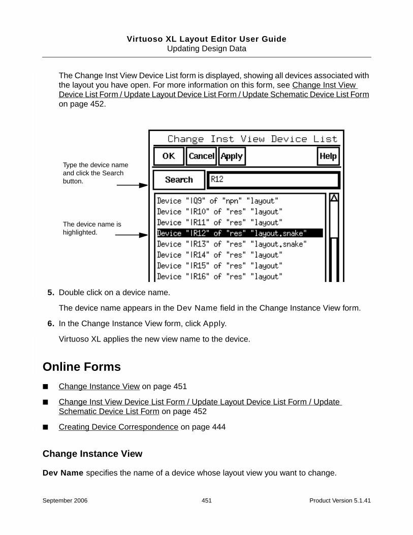
Virtuoso XL Layout Editor User GuideUpdating Design Data
The Change Inst View Device List form is displayed, showing all devices associated withthe layout you have open. For more information on this form, see Change Inst ViewDevice List Form / Update Layout Device List Form / Update Schematic Device List Formon page 452.
5. Double click on a device name.
The device name appears in the Dev Name field in the Change Instance View form.
6. In the Change Instance View form, click Apply.
Virtuoso XL applies the new view name to the device.
Online Forms
■ Change Instance View on page 451
■ Change Inst View Device List Form / Update Layout Device List Form / UpdateSchematic Device List Form on page 452
■ Creating Device Correspondence on page 444
Change Instance View
Dev Name specifies the name of a device whose layout view you want to change.
The device name ishighlighted.
Type the device nameand click the Searchbutton.
September 2006 451 Product Version 5.1.41
Virtuoso XL Layout Editor User GuideUpdating Design Data
common selects multiple devices whose layout view you want to change to a common layoutview. When common is selected, clicking on Apply associates the cell view displayed in thecyclic field to all the devices chosen (the number shown at the bottom of the form).
Switch to View Name changes to include the name of the device you select (Switch cell“res” to View Name) and lets you choose from the cyclic field the cell view to which you wantto attach the device. The choices shown in the cyclic field are set by the stopList variable.If no cell view is associated with the device you choose, this field is not shown.
n of n fields displays the order and number of devices you have chosen to attach to a givencell view. You can enter data in these fields.
List Devices shows the devices present in your layout and the view names associated witheach.
Change Inst View Device List Form / Update Layout Device List Form /Update Schematic Device List Form
The Device List form shows all the devices in the design. Several Virtuoso XL commands usethe Device List form.
To select a device or devices on which you want to perform an action, click on the device youwant to select, or hold down Control and click to select more than one device.
Search finds and selects the names of devices you specify.
You can type in the field to the right of the Search button:
■ A device name
The Device List form highlights the device and scrolls the list to make the device namevisible.
■ A part of a device name (“IN,” for example)
The Device List form highlights all the devices with “IN” as an element in the name (IN3,IN6, IN7, IN12, for example) and scrolls the list to make the first example visible.
■ A regular SKILL expression using part of a device name (“*mos,” for example)
The Device List form highlights all devices with the string “*mos”, (nmos, pmos, forexample) and scrolls the list to make the first example visible.
September 2006 452 Product Version 5.1.41

Virtuoso XL Layout Editor User GuideUpdating Design Data
Create Device Correspondence
From the Create-Device Correspondence command.
Options allows you to control the display of pins and instances.
Show displays either pins or instances in the schematic and layout list boxes.
Sort By sorts the instances by Instance Name or Master Name.
Show Instance Master Name displays the library, cell, and view name for either theInstance Name or Master Name.
Needed allows you to traverse the schematic down to the symbols that have possible layoutmasters to be instantiated.
Computer Aided recognizes net names and inspects instances connected to these netsAfter the pin correspondence is established, the instances that connect to the outside nets(which have a pin) can be scanned for possible matching groups. The matched objects arepresented in the Device Correspondence form for validation. Upon validation, a new set ofnets is recognized.
Next allows you to search for objects by using the filters provided at the top of each list box.Use the Next button to go to the next search result.
Right List Box lists the connectivity source.
Left List Box list the layout to be mapped to the connectivity source.
Map verifies the consistency of the selected set.
Unmap is a a reverse action of the Map button. The mappings that you create can beunmapped without creating Virtuoso XL names.
Next allows you to search for a mapped objects by using the filters provided at the top of eachlist box. Use the Next button to go to the next search result.
Bottom List Box shows objects that have been mapped.
Bottom Left List Box (Computer Aided Mode only) shows the proposed matches to bevalidated.
Message displays what action you need to take next.
September 2006 453 Product Version 5.1.41

Virtuoso XL Layout Editor User Guide
13Troubleshooting
This chapter tells you what to do if unexpected results occur during the Virtuoso XL designprocess. It covers the following topics.
Problems with the Interface
■ Invalid Markers from Previous Software Versions on page 455
■ Options Form Does Not Appear on page 456
■ Virtuoso XL Performance Is Slow on page 457
Problems with Editing
■ Components Move Slowly on page 457
■ Extra Probes Appear on page 457
■ Layout Generation Options Form Does Not Keep Values from the Last Entry on page 458
■ Parameters Not Updated on page 458
■ Schematic Not Editable on page 458
■ Warning to Update Your Design Appears at Startup on page 458
Problems with Connectivity
■ Connections Not Made on page 459
■ Incomplete Nets Command Does Not Recognize Connected Pins and Nets on page 459
■ Markers for Nonexistent Overlaps and Shorts Appear on page 460
■ Path Ends Not Accepted on page 460
■ Placement and Routing Do Not Run on page 461
September 2006 454 Product Version 5.1.41
Virtuoso XL Layout Editor User GuideTroubleshooting
■ Virtuoso XL Does Not Recognize Physical Vias on page 461
■ Moving Software Executables To a New Location on page 461
Problems with Cloning
■ Structure Already Exists in the Layout on page 462
■ Connectivity Structure is Different on page 463
■ Master Cells are Different on page 463
■ More Source Components are Selected than Target Components on page 464
■ Properties are Different on page 465
Problems with Pick From Schematic
■ Hierarchical Designs on page 467
■ Global Terminals and Implicit Inherited Connection Terminals on page 467
Problems with Parameter Evaluation
■ Netlisting Mode on page 467
Problems with the Interface
Invalid Markers from Previous Software Versions
If you are opening layouts you developed using previous versions of Virtuoso software, youcan clean up the layout window and get rid of invalid markers.
1. From the layout window, choose Connectivity – Update – Components and Nets.
Virtuoso XL resynchronizes the layout connectivity with the schematic connectivity.
2. From the layout window, choose Verify – Markers – Delete All.
The markers disappear.
3. Choose Design – Save.
4. From the layout window, choose Window – Close.
September 2006 455 Product Version 5.1.41

Virtuoso XL Layout Editor User GuideTroubleshooting
The layout window closes.
5. From the schematic window, choose Window – Close.
6. The schematic window closes.
7. From the Command Interpreter Window (CIW), choose File – Open.
The Open File form is displayed.
8. From the Library Name cyclic field, choose the library name of your design.
9. In the Cell Name field, type or select from the Cell Names list the cell name of yourdesign.
10. From the View Name cyclic field, choose the view name of your design.
11. Click OK.
The layout window appears, displaying the updated layout configuration.
12. In the layout window, choose Tools – Layout XL.
The Layer Selection Window (LSW) and the schematic view appear.
Note: If you still have problems, make sure that lxExtractLayers is defined.
Options Form Does Not Appear
When you press F3 to see an options form listing possible choices for a command and thecommand does not have an options form, the message box shown below appears:
September 2006 456 Product Version 5.1.41

Virtuoso XL Layout Editor User GuideTroubleshooting
If you want the message box to appear every time you press F3 for a command that has nooptions form, click Yes.
If you do not want the message box to appear every time you press F3 for a command thathas no options form, click No.
Virtuoso XL Performance Is Slow
The following considerations can help you optimize Virtuoso XL performance speed.
■ Virtuoso XL is targeted for use in designs with fewer than 10,000 devices. Theperformance of the online extractor degrades substantially beyond that limit.
■ Incomplete net information is updated after every edit. If you have many incomplete nets,Virtuoso XL might take longer to redisplay your design. Consider turning off ShowIncomplete Nets when working on interconnect layers. Use the highlighting features ofthe path command or probing to determine connections or display only nets you areworking on or that are relevant to the current task.
■ If you need extra pins in the layout for feedthrough nets or substrate connections,consider adding those after you have completed the main portion of the design. Addingextra pins increases the number of nets the extractor manages and degradesperformance.
■ Define lxExtractLayers only on layers to be used as interconnect during wiringwith Virtuoso XL. Using more layers than necessary causes the extractor to check allshapes on those layers, which slows performance. If you do not have interconnect towells, do not make the well layers lxExtractLayers.
Problems with Editing
Components Move Slowly
If you find that the Move command works too slowly, especially when you have many iteratedinstances, turn off the layout window Connectivity – Show Incomplete Nets command ordisplay only nets that are relevant to the current task.
Extra Probes Appear
To delete unwanted probes in the schematic or layout windows, while the Probe command isactive,
September 2006 457 Product Version 5.1.41

Virtuoso XL Layout Editor User GuideTroubleshooting
➤ Click on an empty space in the design.
or at any time
➤ Press Control-Shift-L.
Layout Generation Options Form Does Not Keep Values from the LastEntry
The Layout Generation Options form displays default values each time it opens, it does notcarry over values from the previous entry. If you want to use values from a previous entry, youmust save these values to a template and then use the Load option on the form to open thetemplate and update the fields in the form with the information in the template.
Parameters Not Updated
If the parameters are not updated the way you expect, check for the presence of thelxParamsToIgnore property on components of your design.
Schematic Not Editable
If you cannot make changes to the schematic,
■ Check that the schematic is editable (the Schematic window Design menu shows theMake Read Only command, not the Make Editable command).
■ Check with your system administrator that you have a license for the Virtuoso schematiceditor (product 302).
Warning to Update Your Design Appears at Startup
When you open a design in Virtuoso XL and an Info window similar to this appears, it meansthat the schematic has been changed after the last time the layout was changed, so the layoutis not the latest version of the design.
You can update the layout from the changed schematic by using the layout windowConnectivity – Check – Against Source command and then using either the
September 2006 458 Product Version 5.1.41

Virtuoso XL Layout Editor User GuideTroubleshooting
Connectivity – Update – Components and Nets or Connectivity – Update – DeviceCorrespondence commands as needed.
Problems with Connectivity
Connections Not Made
If the software does not accept an electrical connection you make, make sure that thefollowing information is set in the technology file:
■ Connectivity information in the lxRules class
❑ lxExtractLayers (leConducting in version 4.3.4 and earlier) definesconducting layers
❑ lxNoOverlapLayers (leOverlap in version 4.3.4 and earlier) defines layers thatmust not overlap
■ Layer information in the layerRules class
❑ equivalentLayers (leEquivalent in version 4.3.4 and earlier) defines layersthat are electrically equivalent
❑ viaLayers (leEquivalent in version 4.3.4 and earlier) defines layers used forvias and the layers they connect
Also check that the layer properties were set when you made the connection.
Incomplete Nets Command Does Not Recognize Connected Pins and Nets
If a pin is connected to a net but has the lxBlockExtractCheck property on it, theincomplete nets command does not recognize that the pin is connected.
Virtuoso XL Info
The schematic information has changed since this layout was last generatedor updated. To insure a correct layout, you should run Connectivity - Check -Against Source to determined what has changed.
September 2006 459 Product Version 5.1.41

Virtuoso XL Layout Editor User GuideTroubleshooting
If a layer you use for pcells is not listed in the technology file in the lxExtractLayers list,the incomplete nets command does not recognize incomplete nets noted on that layer.Furthermore, the probe code does not highlight any layer that is not listed in the technologyfile in the lxExtractLayers list.
Markers for Nonexistent Overlaps and Shorts Appear
If there are markers for nonexistent overlaps and shorts in the layout, make sure that theappropriate layer was active when the path was created.
If this does not fix the problem, make sure that the connectivity information(lxExtractLayers and lxNoOverlapLayers) and layer information(equivalentLayers and viaLayers) are set correctly in the technology file.
Path Ends Not Accepted
If the software rejects the final segment of a path or wire connection and displays the followingmessage.
First or last segment of created path has length less than or equal to half thepath width
➤ Press Return to end a path instead of double clicking the mouse (do not double clickto end a path).
or
➤ Set the layout window Design – Options – Display command to a snap mode otherthan x-first or y-first.
When you use the x-first or y-first snap modes, the double click often makes a notch in thepath, which triggers the error message and can cause errors in mask layout.
Notch
September 2006 460 Product Version 5.1.41

Virtuoso XL Layout Editor User GuideTroubleshooting
Placement and Routing Do Not Run
Virtuoso XL does not let you place or route the elements of a design unless you have definedwhich layers of your layout design are conducting layers.
If you try to place or route your design before defining the conducting layers, you get an errormessage like this.
Define the layers you want to be conducting layers as lxExtractLayers in the lxRulesclass of the technology file.
Virtuoso XL Does Not Recognize Physical Vias
If you have an existing design in which Virtuoso XL does not recognize physical vias, youneed to add a property with name = “function”, value = “via” to the master cellview of the viaor to the component description format (CDF) for via layout.
Moving Software Executables To a New Location
If you move software executables to a different location other than specified by manufacturing,the Virtuoso custom placer may take longer to start because it is searching for the executable.
Problems with Cloning
If a target cannot be cloned, no outline of the layout structure appears and a dialog box isdisplayed with the following message.
Cloning could not be completed.
Check for:
There are no ‘lxExtractLayers’ defined in library ‘cmos_test’.
To get Virtuoso XL connectivity, you need to update your technology file.
Close
Virtuoso XL
September 2006 461 Product Version 5.1.41

Virtuoso XL Layout Editor User GuideTroubleshooting
Target partially implemented
Connectivity Structure mismatch
Mismatch of parameters or masters
Structure Already Exists in the Layout
The structure or part of the structure that you selected as the target already exists in thelayout. For example, here R1, R2, and Q1 in the layout were the source components and R4(which is already implemented), R5, and Q2 were the target components.
R1
R2
R4
Q1
R5
Q2
Cannot be placedas clones ofR!/R2/R5combinationbecause R4 is alreadyplaced.
September 2006 462 Product Version 5.1.41
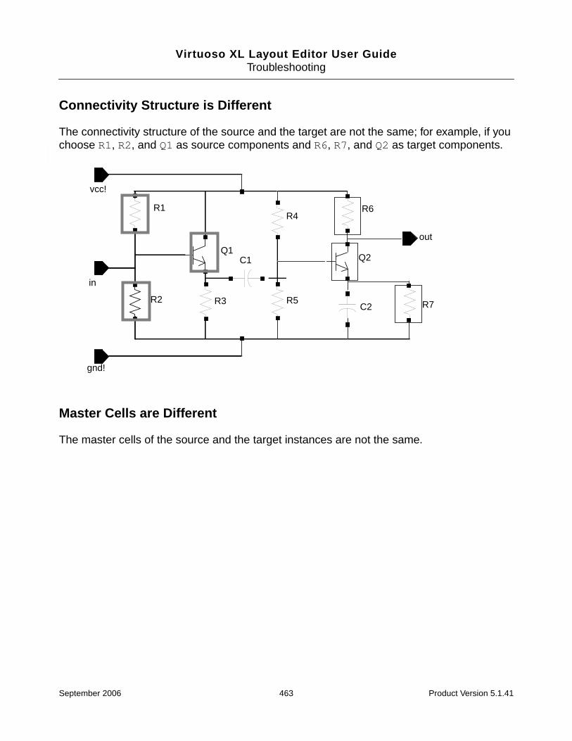
Virtuoso XL Layout Editor User GuideTroubleshooting
Connectivity Structure is Different
The connectivity structure of the source and the target are not the same; for example, if youchoose R1, R2, and Q1 as source components and R6, R7, and Q2 as target components.
Master Cells are Different
The master cells of the source and the target instances are not the same.
R1
R2
R6
R7R5
R4
R3
C1
C2
Q2Q1
vcc!
gnd!
in
out
September 2006 463 Product Version 5.1.41

Virtuoso XL Layout Editor User GuideTroubleshooting
More Source Components are Selected than Target Components
More source components are selected than target components. For example, if you selectedR1, R2, and Q1 as source components and selected only R4 and Q2 for target components.
R1
R2
R6
R7R5
R4
R3
C1
C2
Q2Q1
vcc!
gnd!
in
outr=5Kr=5K r=5K
r=5K r=10Kr=5K
September 2006 464 Product Version 5.1.41

Virtuoso XL Layout Editor User GuideTroubleshooting
Properties are Different
The properties of the source and target instances are not the same. For example, you couldnot use R1 and R2 in this diagram to clone R4 and R5 because their resistance valueproperties are different.
The target instance can have properties that are additional to the properties of the sourceinstance, but the target instance must have all the same properties with the same values asthe source instance has.
R1
R2
R6
R7R5
R4
R3
C1
C2
Q2Q1
vcc!
gnd!
in
outr=10Kr=5K r=5K
r=2.5K r=2.5Kr=5K
September 2006 465 Product Version 5.1.41

Virtuoso XL Layout Editor User GuideTroubleshooting
In the example below, you can use R1, R2, and Q1 as source components to clone R4,R5, and Q2 because the targets have the same properties and values as the sources,even though one of the targets has additional properties.
You can assign the property lxParamsToIgnore to source instances with properties that aredifferent from the target instance properties, so that the source instances can be clonedsuccessfully as target instances.
Problems with Pick From Schematic
If the Create – Pick From Schematic command fails, check that
■ The instance is not already placed in the layout.
If it is already placed, you cannot use Create – Pick From Schematic to place it again.
■ All of the required masters and reference views are present, including
❑ The default layout master for the specified schematic component.
❑ Any layout master specified by the useCell attribute for the schematic instance ormaster.
❑ The required layout view as derived from the stopList.
R1
R2
R6
R7R5
R4
R3C1
C2
Q2Q1
vcc!
gnd!
in
outr=5Kr=5K r=5K
r=5K r=2.5Kr=5K
l=5w=3
September 2006 466 Product Version 5.1.41

Virtuoso XL Layout Editor User GuideTroubleshooting
Hierarchical Designs
If you push into a hierarchical schematic view beyond the layout stop point, you cannot usethe Create – Pick From Schematic command to generate lower-level instances inside thattop-level cell.
For example, assume there is a layout view derived from the specified stopListcorresponding to a cell1 instantiated in the schematic. If you descend into an instance ofcell1 and try to generate the lower-level instances, the command fails.
Global Terminals and Implicit Inherited Connection Terminals
Create – Pick From Schematic does not generate global terminals or implicit inheritedconnection terminals (i.e., wires with netSet properties).
Problems with Parameter Evaluation
Netlisting Mode
To ensure that CDF parameters are always evaluated correctly, make sure that theCDS_Netlisting_Mode shell environment variable is set to Analog.
To set CDS_Netlisting_Mode,
➤ Type the following commands in the CIW.
setShellEnvVar("CDS_Netlisting_Mode=Analog")
cdsSetNetlistMode()
To check which mode is currently set,
➤ Type the following command in the CIW.
cdsGetNetlistMode()
For more information on CDS_Netlising_Mode, see “Customizing the SimulationEnvironment” in the Open Simulation System Reference.
September 2006 467 Product Version 5.1.41

Virtuoso XL Layout Editor User GuideTroubleshooting
Evaluating CDF Callbacks by Default
To ensure that SKILL callbacks defined on CDF parameters (for example, lxCombination)are evaluated by default, you must set the lxEvalCDFCallbacks environment variable to t.
lxEvalCDFCallbacks affects any CDF parameter with a callback that is executedwhenever the value of the parameter changes.
For more information, see “Defining Parameters” in the Component Description FormatUser Guide.
September 2006 468 Product Version 5.1.41

Virtuoso XL Layout Editor User GuideTroubleshooting
September 2006 469 Product Version 5.1.41

Virtuoso XL Layout Editor User Guide
AEnvironment Variables
This appendix provides information on the names, descriptions, and graphical user interfaceequivalents for the Virtuoso® XL Layout Editor (Virtuoso XL) and wire editor environmentvariables.
Important
Only the Virtuoso XL environment variables documented in this chapter aresupported for public use. All other Virtuoso XL environment variables, regardless oftheir name or prefix, and undocumented aspects of the environment variablesdescribed below, are private and are subject to change at any time.
■ Virtuoso XL Layout Editor on page 471
■ Wire Editor on page 607
For more information on setting environment variables, see “Setting Environment Variables”on page 62.
Inherited Environment Variable Settings
Many of the environment variables honored by Virtuoso XL are set in Virtuoso Layout Editor.Information on these environment variables is not duplicated in this section.
For more information on Virtuoso Layout Editor environment variables, see Appendix B,“Environment Variables,” in the Virtuoso Layout Editor User Guide.
September 2006 470 Product Version 5.1.41

Virtuoso XL Layout Editor User GuideEnvironment Variables
Virtuoso XL Layout Editor
abutPerpSnapOn
layout abutPerpSnapOn ’boolean { t | nil }
Description
For information on this environment variable, see abutPerpSnapOn in the Virtuoso LayoutSuite L User Guide.
September 2006 471 Product Version 5.1.41

Virtuoso XL Layout Editor User GuideEnvironment Variables
allowRotation
layoutXL.placement allowRotation ’boolean { t | nil }
Description
Specifies whether the Virtuoso custom placer can rotate components as part of itsoptimization. If this variable is set to nil, the placer can move components but not rotatethem.
The default is t.
GUI Equivalent
Command: Place – Placer
Field: Allow Rotation
September 2006 472 Product Version 5.1.41

Virtuoso XL Layout Editor User GuideEnvironment Variables
autoAbutment
layoutXL autoAbutment ’boolean { t | nil }
Description
Abuts correctly prepared transistors automatically so that they can share pins.
The default is t.
When autoAbutment is set to t, devices that have not been abutted but are overlapping areabutted automatically.
Note: If the devices are already abutted, the automatic abutment feature does not re-abutthem when you start Virtuoso XL.
GUI Equivalent
Command: Options – Layout XL
Field: Auto Abutment
September 2006 473 Product Version 5.1.41

Virtuoso XL Layout Editor User GuideEnvironment Variables
autoArrange
layoutXL autoArrange ’boolean { t | nil }
Description
Specifies whether Virtuoso XL automatically rearranges the windows on your desktop onstartup.
The default is t.
GUI Equivalent
Command: Options – Layout XL
Field: Auto Arrange Windows
September 2006 474 Product Version 5.1.41
Virtuoso XL Layout Editor User GuideEnvironment Variables
autoExtractEnabled
layoutXL autoExtractEnabled ’boolean { t | nil }
Description
For information on this environment variable, see autoExtractEnabled in the VirtuosoLayout Suite L User Guide.
September 2006 475 Product Version 5.1.41

Virtuoso XL Layout Editor User GuideEnvironment Variables
autoExtractSaveEnabled
layoutXL autoExtractSaveEnabled ’boolean { t | nil }
Description
For information on this environment variable, see autoExtractSaveEnabled in theVirtuoso Layout Suite L User Guide.
September 2006 476 Product Version 5.1.41
Virtuoso XL Layout Editor User GuideEnvironment Variables
autoSpace
layoutXL autoSpace ’boolean { t | nil }
Description
Switches on automatic spacing, which allows components with the propertiesvxlInstSpacingDir and vxlInstSpacingRule to be spaced automatically according to the valuesspecified in the properties.
The default is t.
GUI Equivalent
Command: Options – Layout XL
Field: Auto Space
September 2006 477 Product Version 5.1.41

Virtuoso XL Layout Editor User GuideEnvironment Variables
checkTimeStamps
layoutXL checkTimeStamps ’boolean { t | nil }
Description
Specifies whether Virtuoso XL checks the schematic time stamp and warns you if theschematic has changed since Virtuoso XL generated the corresponding layout.
The default is t.
GUI Equivalent
None.
September 2006 478 Product Version 5.1.41
Virtuoso XL Layout Editor User GuideEnvironment Variables
checkOldIgnoredParamsProps
layoutXL checkOldIgnoredParamsProps ’boolean { t | nil }
Description
Specifies that Virtuoso XL uses the old lxIgnoredParams and lxIgnoreParamsForCASproperties when checking for parameters and properties to be ignored.
By default, Virtuoso XL uses the new lxParamsToIgnore and lxParamsToIgnoreForCheckproperties.
Caution
Enabling this environment variable can adversely affect the performanceof Virtuoso XL.
GUI Equivalent
None.
September 2006 479 Product Version 5.1.41
Virtuoso XL Layout Editor User GuideEnvironment Variables
ciwWindow
layoutXL ciwWindow string pair_of_coordinates
Description
Specifies the position of the command interpreter window (CIW) window on the screen.
The default is ((0 0) (0 0)).
GUI Equivalent
None.
September 2006 480 Product Version 5.1.41

Virtuoso XL Layout Editor User GuideEnvironment Variables
cloningDoExactMatch
layoutXL cloningDoExactMatch ’boolean { t | nil }
Description
Controls whether the instance parameter should be checked when finding a match betweenconnectivity sources and connectivity targets.
GUI Equivalent
Command Create – Clone
Field Exact Match
September 2006 481 Product Version 5.1.41
Virtuoso XL Layout Editor User GuideEnvironment Variables
colorDraglines
layoutXL colorDraglines ’boolean { t | nil }
Description
Displays each dragline in a different color. The color cycle is defined in the Show IncompleteNets form.
This environment variable is honored by the Create – Pick From Schematic, Create –Clone, Edit – Move, and Edit – Stretch commands.
Tip
For more information on displaying draglines, see also hideDraglinesForGlobalNetsand showDraglinesForDistantConns.
GUI Equivalent
Command: Options – Layout XL
Field: Display – Draglines – Use Colors
September 2006 482 Product Version 5.1.41

Virtuoso XL Layout Editor User GuideEnvironment Variables
compTypeRefLibs
layoutXL compTypeRefLibs ’string string
Description
Specifies the names of the reference libraries to which component type definitions areapplied.
The default is none.
GUI Equivalent
Command: Design – Component Types
Field: Ref Libs
September 2006 483 Product Version 5.1.41

Virtuoso XL Layout Editor User GuideEnvironment Variables
constraintAssistedMode
layoutXL constraintAssistedMode ’boolean { t | nil }
Description
Specifies whether the Move and Stretch commands use the algorithms from the constraint-driven placer when placing components in a layout. When set to t, fixed constraints preventlocked objects from being moved and stretched.
The default is nil.
GUI Equivalent
Command: Options – Layout XL
Field: Constraint Assisted Move and Stretch
September 2006 484 Product Version 5.1.41
Virtuoso XL Layout Editor User GuideEnvironment Variables
createBoundaryLabel
layoutXL createBoundaryLabel ’boolean { t | nil }
Description
Specifies whether the Gen From Source command automatically creates a label containingthe library, cell, and view name of the design when creating a boundary from the LayoutGeneration Options form.
The default is nil.
GUI Equivalent
None.
September 2006 485 Product Version 5.1.41

Virtuoso XL Layout Editor User GuideEnvironment Variables
crossSelect
layoutXL crossSelect ’boolean { t | nil }
Description
Specifies whether cross-selection is operational. Cross-selection means that when you selecta component in the layout, the corresponding component is selected in the schematic andvice versa.
The default is t.
GUI Equivalent
Command: Options – Layout XL
Field: Cross Selection
September 2006 486 Product Version 5.1.41

Virtuoso XL Layout Editor User GuideEnvironment Variables
deleteUnmatchedInsts
layoutXL deleteUnmatchedInsts ’boolean { t | nil }
Description
Controls whether or not Virtuoso XL deletes from the layout instances that no longer exist inthe schematic.
The default is nil, meaning that unmatched instances are not deleted when updatingcomponents and nets. Instead unmatched instances are indicated with a marker in the layoutview.
GUI Equivalent
None.
September 2006 487 Product Version 5.1.41

Virtuoso XL Layout Editor User GuideEnvironment Variables
deleteUnmatchedPins
layoutXL deleteUnmatchedPins ’boolean { t | nil }
Description
Controls whether or not Virtuoso XL deletes from the layout pins that no longer exist in theschematic. The advantage of deleting redundant pins is that redundant nets and terminalsare deleted from the layout view at the same time.
The default is nil, meaning that unmatched pins are not deleted when updating componentsand nets. Instead unmatched pins are indicated with a marker in the layout view.
GUI Equivalent
None.
September 2006 488 Product Version 5.1.41

Virtuoso XL Layout Editor User GuideEnvironment Variables
drdUseNetName
layoutXL drdUseNetName ’boolean { t | nil }
Description
Controls whether an object that is being moved retains the net name of the pin or instanceterminal to which it was connected prior to the move. This in turn lets the design-rule-driven(DRD) editing functionality use the name to flag short violations during the move operation.
For example, when using DRD editing, if you move an object on net A towards an object onnet B, the system displays a message warning you about the short violation. If the move leadsto the object becoming disconnected from an I/O pin or instance terminal, thedrdUseNetName environment variable controls the behavior as follows.
■ When set to t, the object retains the net name of the pin or instance terminal to which itwas connected prior to the move and DRD editing uses this name to flag short violations.
■ When set to nil, the object does not retain the net name, Virtuoso XL is unaware of anyconnectivity associated with the object, and therefore no short message is displayed.
The original net assignment remains intact in both cases. The default value is nil.
Additional Information
■ The lxStickyNet property overrides any setting of drdUseNetName. For informationon lxStickyNet, see “Sticky Nets” on page 336.
■ For information on design-rule-driven editing, see “Design-Rule-Driven Editing” in theVirtuoso Layout Editor Turbo User Guide.
■ For information on how drdUseNetName affects DRD editing, see “Editing Commandsin Virtuoso XL Layout Editor” in the Virtuoso Layout Editor Turbo User Guide.
Important
drdUseNetName has no effect when you stretch an object because assignedconnectivity is always maintained during the stretch operation. However, if all thepoints of the object are selected prior to stretching, the stretch is in fact a move andthe behavior is as described above.
GUI Equivalent
None.
September 2006 489 Product Version 5.1.41

Virtuoso XL Layout Editor User GuideEnvironment Variables
extractEnabled
layout extractEnabled ’boolean { t | nil }
Description
For information on this environment variable, see extractEnabled in the Virtuoso LayoutSuite L User Guide.
September 2006 490 Product Version 5.1.41
Virtuoso XL Layout Editor User GuideEnvironment Variables
extractShowMustConnectMarkers
layout extractShowMustConnectMarkers ’boolean { t | nil }
Description
For information on this environment variable, see extractShowMustConnectMarkers inthe Virtuoso Layout Suite L User Guide.
September 2006 491 Product Version 5.1.41

Virtuoso XL Layout Editor User GuideEnvironment Variables
extractShowUnimplementedInstTerms
layout extractShowUnimplementedInstTerms ’boolean { t | nil }
Description
For information on this environment variable, seeextractShowUnimplementedInstTerms in the Virtuoso Layout Suite L User Guide.
September 2006 492 Product Version 5.1.41
Virtuoso XL Layout Editor User GuideEnvironment Variables
extractShowWeakMarkers
layout extractShowWeakMarkers ’boolean { t | nil }
Description
For information on this environment variable, see extractShowWeakMarkers in theVirtuoso Layout Suite L User Guide.
September 2006 493 Product Version 5.1.41

Virtuoso XL Layout Editor User GuideEnvironment Variables
extractStopLevel
layout extractStopLevel ’int { 0 | 1 | 2 | ... | 32 }
Description
For information on this environment variable, see extractStopLevel in the VirtuosoLayout Suite L User Guide.
September 2006 494 Product Version 5.1.41

Virtuoso XL Layout Editor User GuideEnvironment Variables
flightLineEnable
layoutXL flightLineEnable ’boolean { t | nil }
Description
Controls whether draglines are displayed during the Move, Stretch, Pick From Schematic,and Create Clone commands. The draglines connect the pins of the object you are movingto pins of the nearest objects.
The default is t.
For information on how to change the display of the draglines, see colorDraglines,hideDraglinesForGlobalNets, and showDraglinesForDistantConns.
GUI Equivalents
Command: Edit – MoveEdit – Stretch
Field: Display Draglines
Command: Create – Pick From SchematicCreate – Clone
Field: Draglines
September 2006 495 Product Version 5.1.41
Virtuoso XL Layout Editor User GuideEnvironment Variables
globalPlacement
layoutXL.placement globalPlacement ’boolean { t | nil }
Description
Switches on the global placement function, which places components without regard to anyinitial placement. The placer optimizes global objectives such as total wire length and overlapviolations between components might be ignored.
You would typically use this option the first time you place a design or to discard previousunsatisfactory placement results.
The default is t.
GUI Equivalent
Command: Place – Placer
Field: Global Placement
September 2006 496 Product Version 5.1.41
Virtuoso XL Layout Editor User GuideEnvironment Variables
hideDraglinesForGlobalNets
layoutXL hideDraglinesForGlobalNets ’boolean { t | nil }
Description
Hides draglines for global nets and power and ground nets specified using thelxGroundNetNames and lxSupplyNetNames environment variables.
This environment variable is honored by the Create – Pick From Schematic, Create –Clone, Edit – Move, and Edit – Stretch commands.
Tip
For more information on displaying draglines, see also colorDraglines andshowDraglinesForDistantConns.
GUI Equivalent
Command: Options – Layout XL
Field: Display – Draglines – Hide Global Nets
September 2006 497 Product Version 5.1.41

Virtuoso XL Layout Editor User GuideEnvironment Variables
ignoreNames
layoutXL ignoreNames ’string “list_of_properties”
Description
Tip
Cadence recommends that you use the propsUsedToIgnoreObjs andpropsUsedToIgnoreObjsForCheck environment variables instead ofignoreNames.However, ignoreNames, if defined, takes precedence.
Defines a list of properties that cause pins and instances to be ignored during Virtuoso XLupdates. If any of the properties in the ignoreNames list is set to true for a particularinstance then that instance is ignored.
The software searches for the properties in the order in which the names are listed in theenvironment variable. In the example below, the vxlIgnore property is used because it isfirst in the list.
envSetVal(“layoutXL” “ignoreNames” ‘string “vxlIgnore lvsIgnore ignorenlAction”)
You can also use the Layout XL Options form to set the ignoreNames environment variableto define other properties to use as ignore properties. For more information, see “SettingEnvironment Variables” on page 62.
Note: A schematic device that has the string property nlAction with a value of ignorebehaves the same as one with an lvsIgnore or ignore property.
GUI Equivalent
Command: Options – Layout XL
Field: Ignore Names
September 2006 498 Product Version 5.1.41
Virtuoso XL Layout Editor User GuideEnvironment Variables
IgnoredParams
layoutXL IgnoredParams ’string { lxIgnoredParams | dleIgnoredParams | lxStopList |dleStopList | lxUseCell | dleUseCell | maskLayout | ViewName | posi |instancesLastChanged | instNamePrefix | pin# | lxTimeStamp |dleSchExtractPath | xPlacementStatus }
Description
Tip
Cadence recommends that you use the paramsToIgnore environment variableinstead of IgnoredParams. However, IgnoredParams, if defined, takesprecedence.
Lists the parameters that are not reported as mismatches during Connectivity – Check –Against Source and are not updated by the Connectivity – Update – Components andNets command.
The valid values are all the default values plus any other parameters you need to add.
Note: Do not remove the default values for IgnoredParams. The database-specific valuesare used by Virtuoso XL to traverse the schematic.
If there are devices in your schematic with properties that you do not want to be checkedwhen you use the Connectivity – Check – Against Source command or transferred to thelayout when you use the Connectivity – Update – Layout Parameters command, specifythose device parameters to be excluded using the lxIgnoredParams property.
You can also set this property on layout components that are the same except for theirparameters, so that the differing parameters are ignored by the cloning functionality.
For information on the properties mentioned above, see “Properties” on page 736.
GUI Equivalent
Command: Options – Layout XL
Field: Show Parameters to Ignore
September 2006 499 Product Version 5.1.41

Virtuoso XL Layout Editor User GuideEnvironment Variables
IgnoreParamsForCAS
layoutXL IgnoreParamsForCAS ’string string
Description
Specifies a list of parameters and properties to be ignored when using the Connectivity –Check – Against Source command. Instances with any of the listed parameters orproperties are not included in the check.
Important
Cadence recommends that you use the paramsToIgnoreForCheck environmentvariable instead of IgnoreParamsForCAS. However, IgnoreParamsForCAS, ifdefined, takes precedence.
GUI Equivalent
Command: Check – Against Source
Field: None
September 2006 500 Product Version 5.1.41

Virtuoso XL Layout Editor User GuideEnvironment Variables
incNetCycleHilite
layoutXL incNetCycleHilite ’boolean { t | nil }
Description
Controls whether the Show Incomplete Nets command cycles through the y0 through y9drawing layers when displaying incomplete nets. When set to nil, the layer specified in theincNetHiliteLayer environment variable is used to highlight all incomplete nets.
The default is t.
GUI Equivalent
Command: Connectivity – Show Incomplete Nets
Field: Cycle
September 2006 501 Product Version 5.1.41

Virtuoso XL Layout Editor User GuideEnvironment Variables
incNetHiliteLayer
layoutXL incNetHiliteLayer ’string { y1 | ... | y9 }
Can we do better with the input? It currently doesn’t match the description. I.e. do weneed the purpose in the definition?
Description
Specifies which layer the Show Incomplete Nets command uses to display incomplete nets.The environment variable is effective only if the incNetCycleHilite environment variableis set to nil.
The default is y0 drawing.
GUI Equivalent:
Command Connectivity – Show Incomplete Nets
Form Field Cycle
September 2006 502 Product Version 5.1.41

Virtuoso XL Layout Editor User GuideEnvironment Variables
infoWindow
layoutXL infoWindow ’boolean { t | nil }
Description
Controls where messages issued by Virtuoso XL are displayed. When set to t, Virtuoso XLmessages are displayed in a separate Info window. When set to nil, messages are sent tothe CIW.
The default is t.
GUI Equivalent
None.
September 2006 503 Product Version 5.1.41

Virtuoso XL Layout Editor User GuideEnvironment Variables
initAspectRatio
layoutXL initAspectRatio ’float floating_point_number
Description
Specifies the width-to-height aspect ratio of the design to be automatically generated orreinitialized. For example, a value of 1 specifies a square boundary, 0.5 specifies a boundarytwice as high as it is wide, and 2 specifies a boundary twice as wide as it is high.
The default is 1.0.
GUI Equivalent
Command: Design – Gen From Source
Field: Aspect Ratio (W/H)
September 2006 504 Product Version 5.1.41

Virtuoso XL Layout Editor User GuideEnvironment Variables
initAspectRatioOption
layoutXL initAspectRatioOption ’string { Aspect Ratio W/H | Boundary Width |Boundary Height }
Description
Specifies which of the boundary options is set when you open the Layout Generation Optionsform.
The default is Aspect Ratio W/H.
GUI Equivalent
None.
September 2006 505 Product Version 5.1.41

Virtuoso XL Layout Editor User GuideEnvironment Variables
initBoundaryLayer
layoutXL initBoundaryLayer ’string string
Description
Defines the layer Virtuoso XL uses to draw the design boundary in the Virtuoso layoutwindow.
The default is prBoundary drawing.
Note: If the layer purpose pair prBoundary boundary is not defined in the technology file,then prBoundary drawing is used.
So what is the default: “prBoundary boundary” or “prBoundary drawing”? Wheredoes “prBoundary boundary “come into it?
GUI Equivalent
None.
September 2006 506 Product Version 5.1.41

Virtuoso XL Layout Editor User GuideEnvironment Variables
initCreateBoundary
layoutXL initCreateBoundary ’boolean { t | nil }
Description
Controls whether Virtuoso XL creates a design boundary in the Virtuoso layout window.
The default is nil.
GUI Equivalent
Command: Design – Gen From Source
Field: Boundary
September 2006 507 Product Version 5.1.41

Virtuoso XL Layout Editor User GuideEnvironment Variables
initCreateInstances
layoutXL initCreateInstances ’boolean { t | nil }
Description
Specifies that Virtuoso XL is to generate instances during the Design – Gen From Sourcecommand. The default is t.
GUI Equivalent
Command: Design – Gen From Source
Field: Instances
September 2006 508 Product Version 5.1.41

Virtuoso XL Layout Editor User GuideEnvironment Variables
initCreateMTM
layoutXL initCreateMTM ’boolean { t | nil }
Description
Specifies that Virtuoso XL is to preserve existing many-to-many mappings during Design –Gen From Source. The default is t.
GUI Equivalent
Command: Design – Gen From Source
Field: Preserve Mappings
September 2006 509 Product Version 5.1.41

Virtuoso XL Layout Editor User GuideEnvironment Variables
initCreatePins
layoutXL initCreatePins ’boolean { t | nil }
Description
Specifies that Virtuoso XL is to create pins during the Design – Gen From Sourcecommand. The default is t.
GUI Equivalent
Command: Design – Gen From Source
Field: Create
September 2006 510 Product Version 5.1.41

Virtuoso XL Layout Editor User GuideEnvironment Variables
initDoFolding
layoutXL initDoFolding ’boolean { t | nil }
Description
Specifies that Virtuoso XL is to fold prepared transistors into separate fingers during Design– Gen From Source. The default is nil.
GUI Equivalent
Command: Design – Gen From Source
Field: Transistor Folding
September 2006 511 Product Version 5.1.41

Virtuoso XL Layout Editor User GuideEnvironment Variables
initDoStacking
layoutXL initDoStacking ’boolean { t | nil }
Description
Specifies that Virtuoso XL is to abut MOS transistors in a specific order during Design – GenFrom Source. The default is nil.
GUI Equivalent
Command: Design – Gen From Source
Field: Transistor Chaining
September 2006 512 Product Version 5.1.41

Virtuoso XL Layout Editor User GuideEnvironment Variables
initEstimateArea
layoutXL initEstimateArea ’boolean { t | nil }
Description
Determines whether Virtuoso XL estimates the size of the design boundary based on theBoundary Area Estimation options in the Layout Generation Options form.
The default is t.
GUI Equivalent
Command: Design – Gen From Source
Field: Boundary Area Estimation groupbox
September 2006 513 Product Version 5.1.41

Virtuoso XL Layout Editor User GuideEnvironment Variables
initGlobalNetPins
layoutXL initGlobalNetPins ’boolean { t | nil }
Description
Determines whether Virtuoso XL Gen from Source command creates pins for global nets.The default is t.
GUI Equivalent
Command: Design – Gen From Source
Field: I/O Pins
September 2006 514 Product Version 5.1.41
Virtuoso XL Layout Editor User GuideEnvironment Variables
initIOLabelType
layoutXL initIOLabelType ’string { Label | Text Display | None }
Description
Specifies the type of label that Virtuoso XL generates for I/O pins. When set to None, no pinlabel is created.
This setting is honored by the Gen From Source and Pick From Schematic commands.
The default is Label.
Important
Virtuoso XL does not create labels for symbolic pins.
Note: For initIOLabelType to take effect, you must set the Layout L environment variablecreatePinLabel to t. For information on createPinLabel, see Appendix B,“Environment Variables,” in the Virtuoso Layout Editor User Guide.
GUI Equivalent
Command: Design – Gen From Source
Field: Pin Label Shape
September 2006 515 Product Version 5.1.41

Virtuoso XL Layout Editor User GuideEnvironment Variables
initIOPinLayer
layoutXL initIOPinLayer ’string “layer_purpose_pair”
Description
Specifies which of the layers defined in the technology file is used as the pin layer when youchoose the Gen from Source or Update – Components and Nets commands.
The default value is the current entry layer and purpose from the LSW.
Arguments
GUI Equivalent
layer_purpose_pair
Specifies the layer and purpose on which pins are created. Thestring must be enclosed in quotation marks; for example,
“metal1 drawing”
Command: Design – Gen From Source
Field: Layer
September 2006 516 Product Version 5.1.41

Virtuoso XL Layout Editor User GuideEnvironment Variables
initIOPinName
layoutXL initIOPinName ’string string
Description
Specifies the name of the pins generated when you use the Gen from Source or UpdateComponents and Nets command.
GUI Equivalent
Command: Design – Gen From Source
Field: Master
September 2006 517 Product Version 5.1.41
Virtuoso XL Layout Editor User GuideEnvironment Variables
initPinHeight
layoutXL initPinHeight ’float floating_point_number
Description
Specifies the pin height used when you choose the Gen from Source or UpdateComponents and Nets command.
GUI Equivalent
Command: Design – Gen From Source
Field: Height
September 2006 518 Product Version 5.1.41

Virtuoso XL Layout Editor User GuideEnvironment Variables
initPinMultiplicity
layoutXL initPinMultiplicity ’int integer
Description
Specifies the number of pins for each type to be placed.
Default?
GUI Equivalent
Command: Design – Gen From Source
Field: Num
September 2006 519 Product Version 5.1.41
Virtuoso XL Layout Editor User GuideEnvironment Variables
initPinWidth
layoutXL initPinWidth ’float floating_point_number
Description
Specifies the pin width used when you choose the Gen from Source or UpdateComponents and Nets command.
GUI Equivalent
Command: Design – Gen From Source
Field: Width
September 2006 520 Product Version 5.1.41

Virtuoso XL Layout Editor User GuideEnvironment Variables
initPrBoundaryH
layoutXL initPrBoundaryH ’float floating_point_number
Description
Specifies the height of the design boundary used when you choose the Gen from Sourceor Update Components and Nets command. The default is 10.0 or the last value.
GUI Equivalent
Command: Design – Gen From Source
Field: Boundary Height
September 2006 521 Product Version 5.1.41

Virtuoso XL Layout Editor User GuideEnvironment Variables
initPrBoundaryW
layoutXL initPrBoundaryW ’float floating_point_number
Description
Specifies the width of the design boundary used when you choose the Gen from Source orUpdate Components and Nets command. The default is 10.0 or the last value.
GUI Equivalent
Command: Design – Gen From Source
Field: Boundary Width
September 2006 522 Product Version 5.1.41
Virtuoso XL Layout Editor User GuideEnvironment Variables
initSymbolicPins
layoutXL initSymbolicPins ’boolean { t | nil }
Description
Determines whether or not Virtuoso XL creates symbolic pins. The default is nil.
GUI Equivalent
Command: Design – Gen From Source
Field: Pin Type
September 2006 523 Product Version 5.1.41
Virtuoso XL Layout Editor User GuideEnvironment Variables
initUtilization
layoutXL initUtilization ’float floating_point_number
Description
Specifies the percentage of area within the design boundary that is filled when the BoundaryArea Estimation options are used in the Layout Generation Options form. The utilizationvalue is applied and the boundary calculated only after any chaining and folding is complete.
The default is 25.0.
GUI Equivalent:
Command Design – Gen From Source
Form Field Utilization (%)
September 2006 524 Product Version 5.1.41

Virtuoso XL Layout Editor User GuideEnvironment Variables
layoutWindow
layoutXL layoutWindow ’string pair_of_coordinates
Description
Determines the position of the layout window when Virtuoso XL is initiated. The default is ((00) (0 0)).
GUI Equivalent
None.
September 2006 525 Product Version 5.1.41

Virtuoso XL Layout Editor User GuideEnvironment Variables
lswWindow
layoutXL lswWindow ’string pair_of_coordinates
Description
Determines the position of the layer selection window (LSW) when Virtuoso XL is initiated.The default is ((0 0) (0 0)).
GUI Equivalent
None.
September 2006 526 Product Version 5.1.41
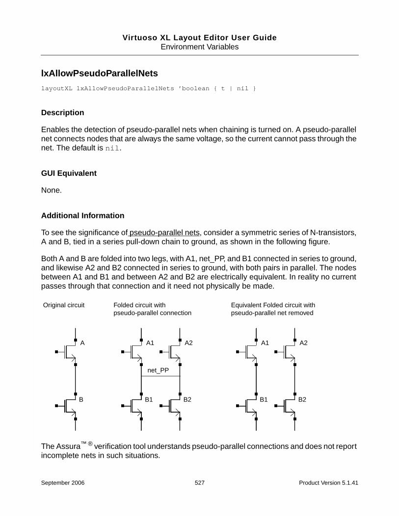
Virtuoso XL Layout Editor User GuideEnvironment Variables
lxAllowPseudoParallelNets
layoutXL lxAllowPseudoParallelNets ’boolean { t | nil }
Description
Enables the detection of pseudo-parallel nets when chaining is turned on. A pseudo-parallelnet connects nodes that are always the same voltage, so the current cannot pass through thenet. The default is nil.
GUI Equivalent
None.
Additional Information
To see the significance of pseudo-parallel nets, consider a symmetric series of N-transistors,A and B, tied in a series pull-down chain to ground, as shown in the following figure.
Both A and B are folded into two legs, with A1, net_PP, and B1 connected in series to ground,and likewise A2 and B2 connected in series to ground, with both pairs in parallel. The nodesbetween A1 and B1 and between A2 and B2 are electrically equivalent. In reality no currentpasses through that connection and it need not physically be made.
The Assura™ ® verification tool understands pseudo-parallel connections and does not reportincomplete nets in such situations.
A
B
Original circuit
A1
B1
A2
B2
net_PP
A1
B1
A2
B2
Folded circuit withpseudo-parallel connection
Equivalent Folded circuit withpseudo-parallel net removed
September 2006 527 Product Version 5.1.41

Virtuoso XL Layout Editor User GuideEnvironment Variables
lxDeltaWidth
layoutXL lxDeltaWidth ’float floating_point_number
Description
Determines the effective width of folded transistors. The effective total width is defined asWeff = M (W + lxDeltaWidth)where M is the number of fingers and W is the identical width of each transistor.
GUI Equivalent
None.
September 2006 528 Product Version 5.1.41
Virtuoso XL Layout Editor User GuideEnvironment Variables
lxEvalCDFCallbacks
layoutXL lxEvalCDFCallbacks ’boolean { t | nil }
Description
Causes any SKILL callbacks defined on CDF parameters to be evaluated by default. Thecallbacks are evaluated in the order in which they are listed in the CDF.
Important
lxEvalCDFCallbacks affects any CDF parameter with a callback that is executedwhenever the value of the parameter changes.
For more information, see “Defining Parameters” in the Component DescriptionFormat User Guide.
The default is nil.
GUI Equivalent
None.
September 2006 529 Product Version 5.1.41

Virtuoso XL Layout Editor User GuideEnvironment Variables
lxFingeringNames
layoutXL lxFingeringNames ’string string
Description
Specifies property names other than fingers or finger to split the number of fingers. Thedefault is finger and fingers.
GUI Equivalent
Command: Options – Layout XL
Field: pCell fingering Names
September 2006 530 Product Version 5.1.41

Virtuoso XL Layout Editor User GuideEnvironment Variables
lxGenerationOrientation
layoutXL lxGenerationOrientation ’string string
Description
Lets you control the orientation of Virtuoso XL layout devices generated from the schematic.The default is preserved, where there is no change in device orientation.
GUI Equivalent
None.
September 2006 531 Product Version 5.1.41

Virtuoso XL Layout Editor User GuideEnvironment Variables
lxGenerationTopLevelOnly
layoutXL lxGenerationTopLevelOnly ’boolean { t | nil }
Description
Generates layout instances only from top-level schematic instances during the Design –Gen From Source and the Create – Pick From Schematic commands. Hierarchicalschematic instances are not generated in the layout.
The default is nil.
GUI Equivalent
None.
September 2006 532 Product Version 5.1.41

Virtuoso XL Layout Editor User GuideEnvironment Variables
lxGetSignifDigits
layoutXL lxGetSignifDigits ’cyclic { 0 | 3 | 4 ... 30 }
Description
Controls the number of significant digits used by Virtuoso XL when calculating the value oflayout CDF parameters.
When set, lxGetSignifDigits overrides the setting of aelGetSignifDigits forcalculations in the layout cellview. This lets you specify a different precision to be used inlayout cellview calculations; for example, those involving parameterized cells.
Valid values are 0 and any integer between 3 and 30. The default is 0, which means that theenvironment variable is switched off. The higher the value you set, the more precise are thevalues used in the calculations.
GUI Equivalent
None.
September 2006 533 Product Version 5.1.41
Virtuoso XL Layout Editor User GuideEnvironment Variables
lxGroundNetNames
layoutXL lxGroundNetNames ’string string
Description
To achieve optimized chaining results in Virtuoso XL device level (i.e. flat) schematics, youcan set the environment variable lxGroundNetNames to specify the ground net name.
The default values are gnd, gnd!, gnd:, vss, vss!, and vss:.
Note: The lxGroundNetNames environment variable can also be used by the Virtuosoplacer to filter out ground nets. The placer would not consider wire length for ground netsduring placement.
GUI Equivalent
None.
September 2006 534 Product Version 5.1.41

Virtuoso XL Layout Editor User GuideEnvironment Variables
lxInitResetSource
layoutXL lxInitResetSource ’boolean { t | nil }
Description
If set to t, prompts you to reset the source before starting Virtuoso XL from the layout. Thedefault is nil.
GUI Equivalent
None.
September 2006 535 Product Version 5.1.41
Virtuoso XL Layout Editor User GuideEnvironment Variables
lxLocalAbutment
layoutXL lxLocalAbutment ’boolean { t | nil }
Description
Controls device abutment in layout editing mode and unabutment during property edits.
The default is nil, which means that when you open a layout view in Virtuoso XL, the toolautomatically abuts any devices which overlap but have not been abutted previously. If thedevices are already abutted, they are not re-abutted.
If lxLocalAbutment is set to t,
■ Devices are not abutted automatically when you open a cellview in Virtuoso XL. Thesoftware automatically abuts only objects that are subsequently edited interactively.
■ Devices are not unabutted and re-abutted during when you change a property on thecellview.
GUI Equivalent
None.
September 2006 536 Product Version 5.1.41
Virtuoso XL Layout Editor User GuideEnvironment Variables
lxSchExtractTopLevelOnly
layoutXL lxSchExtractTopLevelOnly ’boolean { t | nil }
Description
When the lxSchExtractTopLevelOnly environmental variable is set to t, then only thetop-level of the schematic is extracted. Virtuoso XL extracts the schematic only when neededwhen the following commands are invoked; Update Components and Nets, Gen FromSource, Check Against Source, Update Device Correspondence, and Cloning. Thelower level schematics are not extracted, even if they need to be extracted. The default isnil.
GUI Equivalent
None.
September 2006 537 Product Version 5.1.41

Virtuoso XL Layout Editor User GuideEnvironment Variables
lxStackMinimalFolding
layoutXL lxStackMinimalFolding ’boolean { t | nil }
Description
Controls folding to yield the minimum number of legs for each folded device. If set to t, thefolding will yield the minimal number of fingers, whether it is even or odd. The default is nil.
GUI Equivalent
Command: Options – Layout XL
Field: Generate Minimal Folding
September 2006 538 Product Version 5.1.41

Virtuoso XL Layout Editor User GuideEnvironment Variables
lxStackPartitionParameters
layoutXL lxStackPartitionParameters ’string "(integer integer)"
Description
Sets the device chaining partition parameters.
The first integer controls how far up the hierarchy Virtuoso XL looks for opportunities to abutdevices. A value of 1 permits abutment of devices only within the same gate. A value of 2permits abutment of any devices in the same master. Higher values permit abutment withdevices at progressively higher levels of the design hierarchy.
The second value sets the maximum number of devices permitted in a chain.
The default is "(1 100)".
GUI Equivalent
None.
September 2006 539 Product Version 5.1.41

Virtuoso XL Layout Editor User GuideEnvironment Variables
lxSupplyNetNames
layoutXL lxSupplyNetNames ’string string
Description
To achieve optimized chaining results in Virtuoso XL device level (i.e. flat) schematics, youcan set the environment variable lxSupplyNetNames to specify the power net name.
Default values are vcc, vcc!, vcc:, vdd, vdd!, and vdd:.
Note: The lxSupplyNetNames environment variable can also be used by the Virtuosoplacer to filter out power nets. The placer would not consider wire length for supply netsduring placement.
GUI Equivalent
None.
September 2006 540 Product Version 5.1.41

Virtuoso XL Layout Editor User GuideEnvironment Variables
lxToggleLocalAbutment
hiSetBindKey(“Layout” “<Key>” “lxToggleLocalAbutment()”)
Description
A user-defined bindkey that toggles the lxLocalAbutment environment variable.
For more information, see “lxLocalAbutment” on page 536.
GUI Equivalent
None.
September 2006 541 Product Version 5.1.41

Virtuoso XL Layout Editor User GuideEnvironment Variables
lxUseLibList
layoutXL lxUseLibList ’string list_of_libraries
Description
Specifies a list of libraries for Virtuoso XL to search for a layout view that corresponds to aparticular schematic or symbol view.
When generating or updating layout components from a schematic or symbol view, VirtuosoXL uses the layout cellview specified by the lxUseCell property for the schematic or symbolin question.
If lxUseCell is not specified, Virtuoso XL searches for a layout cellview of the same namestored in the same library as the schematic or symbol cellview. If there is no such cellview,the software searches any libraries specified by lxUseLibList.
The software searches the libraries in the sequence in which they are listed and uses the firstlayout cellview it finds with a name that matches the name of the schematic or symbol. If it isunable to find a corresponding layout cellview, the software issues a warning message.
The following commands honor the lxUseLibList environment variable.
■ Design – Gen From Source
■ Create – Clone
■ Create – Pick From Schematic
■ Edit – Transistor Chaining
■ Edit – Transistor Folding
■ Connectivity – Check – Against Source
■ Connectivity – Update – Components and Nets
■ Connectivity – Update – Device or Schematic Parameters
GUI Equivalent
None.
September 2006 542 Product Version 5.1.41

Virtuoso XL Layout Editor User GuideEnvironment Variables
lxWidthTolerance
layoutXL lxWidthTolerance ’string pair_of_coordinates
Description
Sets the allowed device width variation for folding. Of the two positive numbers provided asthe value, the first in the list is the absolute value of the negative tolerance; the second is thepositive tolerance. The default is ((0 0) (0 0)).
GUI Equivalent
None.
September 2006 543 Product Version 5.1.41

Virtuoso XL Layout Editor User GuideEnvironment Variables
maintainConnections
layoutXL maintainConnections ’boolean { t | nil }
Description
Enables the automatic Maintain Connections option when Virtuoso XL is initiated. Thedefault is nil.
GUI Equivalent
Command: Options – Layout Editor
Field: Maintain Connections
September 2006 544 Product Version 5.1.41
Virtuoso XL Layout Editor User GuideEnvironment Variables
mfactorNames
layoutXL mfactorNames ’string “list_of_names”
Description
Lists the names of properties used in the schematic to specify the multiplication factor(mfactor) for transistors.
The default is “m M”.
Note: The mfactor property value can be expressed as an integer or an expression.
Arguments
GUI Equivalent
list_of_names
A list of mfactor property names each separated by a space.The list must be enclosed in quotation marks; for example,
“m M”
Command: Options – Layout XL
Field: mfactor Names
September 2006 545 Product Version 5.1.41

Virtuoso XL Layout Editor User GuideEnvironment Variables
mfactorSplit
layoutXL mfactorSplit ’boolean { t | nil }
Description
Controls whether Virtuoso XL places schematic devices with the mfactor property as multipledevices in the layout.
The default is t.
Note: You can override this environment variable for a given instance by setting the booleanproperty lxMfactorSplit.
GUI Equivalent
Command: Options – Layout XL
Field: Generate Multiple Instances
September 2006 546 Product Version 5.1.41

Virtuoso XL Layout Editor User GuideEnvironment Variables
mfactorSplitParamNames
layoutXL mfactorSplitParamNames ’string “list_of_parameters”
Description
Lists the names of the device parameters to be calculated or checked during Design – GenFrom Source, Connectivity – Check – Against Source, Connectivity – Update –Layout Parameters.
Virtuoso XL checks each instance for the listed parameter names and changes or updatesthe value of the matching parameters such that
number of mfactored instances * mfactorSplit value = source parameter value
The default value is “w”.
Important
Virtuoso XL currently checks only for width parameters.
Arguments
GUI Equivalent
list_of_parameters
A list of parameter names each separated by a space. The listmust be enclosed in quotation marks; for example,
“w”
Command: Options – Layout XL
Field: mfactor Split Param Names
September 2006 547 Product Version 5.1.41
Virtuoso XL Layout Editor User GuideEnvironment Variables
moveAsGroup
layoutXL moveAsGroup ’boolean { t | nil }
Description
Determines whether or not to move groups of components bound by placement constraintsas a unit. The default is t.
GUI Equivalent
Command: Edit – Move
Field: together
September 2006 548 Product Version 5.1.41
Virtuoso XL Layout Editor User GuideEnvironment Variables
openWindow
layoutXL.placement openWindow ’boolean { t | nil }
Description
Opens a window. The default is nil.
GUI Equivalent
Command: Place – Placer
Field: Save As
September 2006 549 Product Version 5.1.41

Virtuoso XL Layout Editor User GuideEnvironment Variables
optimizePlacement
layoutXL.placement optimizePlacement ’boolean { t | nil }
Description
Switches on the Optimize Placement option on the Auto Placer form which determineswhether detailed placement passes are run. The default is t.
GUI Equivalent
Command: Place – Placer
Field: Optimize Placement
September 2006 550 Product Version 5.1.41

Virtuoso XL Layout Editor User GuideEnvironment Variables
paramsToIgnore
layoutXL paramsToIgnore ’string “list_of_parameters”
Description
Important
paramsToIgnore has been introduced to replace the IgnoredParamsenvironment variable. In the current release, if IgnoredParams is defined, itsupersedes paramsToIgnore.
Lists the parameters that are ignored by the following Virtuoso XL update and checkcommands.
■ Design – Gen From Source
■ Create – Pick From Schematic
■ Create – Clone
■ Connectivity – Check – Against Source
■ Connectivity – Update – Components and Nets
■ Connectivity – Update – Layout Parameters
■ Connectivity – Update – Schematic Parameters
The following parameters are always ignored.
dleIgnoredParams dleSchExtractPath dleStopList dleUseCellinstancesLastChanged instNamePrefixlxIgnoredParams lxIgnoreParamsForCAS lxIgnoredParamsForChecklxMFactorNum lxParamsToIgnore lxParamsToIgnoreForChecklxPlacementStatus lxStopList lxTimeStamp lxUseCellmaskLayoutViewName pin# posi
Arguments
list_of_parameters
A list of parameter names each separated by a space. The listmust be enclosed in quotation marks.
September 2006 551 Product Version 5.1.41

Virtuoso XL Layout Editor User GuideEnvironment Variables
GUI Equivalent
Command: Options – Layout XL
Field: Generation – Show Parameters to Ignore
September 2006 552 Product Version 5.1.41

Virtuoso XL Layout Editor User GuideEnvironment Variables
paramsToIgnoreForCheck
layoutXL paramsToIgnoreForCheck ’string “list_of_parameters”
Description
Important
paramsToIgnoreForCheck has been introduced to replace theIgnoreParamsForCAS environment variable. In the current release, ifIgnoreParamsForCAS is defined, it supersedes paramsToIgnoreForCheck.
Lists the parameters to be ignored during the Connectivity – Check – Against Sourcecommand. Mismatches for any of the listed parameters are not reported by the check.
The list automatically includes all of the parameters specified by the paramsToIgnoreenvironment variable.
Arguments
GUI Equivalent
list_of_parameters
A list of parameter names each separated by a space. The listmust be enclosed in quotation marks.
Command: Options – Layout XL
Field: Verification – Show Parameters to Ignore
September 2006 553 Product Version 5.1.41
Virtuoso XL Layout Editor User GuideEnvironment Variables
paramTolerance
layoutXL paramTolerance ’float floating_point_number
Description
Specifies the relative tolerance allowed when comparing values between the layout and theschematic.
This tolerance is applied by any function that deals with parameters, including
■ Connectivity – Check – Against Source
■ Connectivity – Update – Layout Parameters
■ Connectivity – Update – Schematic Parameters
The default is 1E-6.
GUI Equivalent
Command: Options – Layout XL
Field: Tolerance
September 2006 554 Product Version 5.1.41

Virtuoso XL Layout Editor User GuideEnvironment Variables
pathLayerFilter
layoutXL pathLayerFilter ’string "list_of_layers"
Description
Specifies the layers to be ignored by the Choose which object to use dialog box when usingthe Change Layer option on the Create Path form; for example,
layoutXL pathLayerFilter string "met1 met2 act"
This means that objects on met1, met2, or act are not listed in the Choose which object touse dialog. If the pathLayerFilter excludes all layers, then the path command reverts tothe LSW for layer selection.
Arguments
GUI Equivalent
list_of_layers
A list of layer names each separated by a space. The list mustbe enclosed in quotation marks; for example,
"met1 met2 act"
Command: Create – Path
Field: Change Layer
September 2006 555 Product Version 5.1.41

Virtuoso XL Layout Editor User GuideEnvironment Variables
pathProbe
layoutXL pathProbe ’boolean { t | nil }
Description
Determines whether the Path command automatically highlights the net attached to theshape under the starting point for the path. It also changes the current layer to the layer of theshape under the starting point for the path.
The default is t.
GUI Equivalent
Command: Create – Path
Field: Probe Nets
September 2006 556 Product Version 5.1.41

Virtuoso XL Layout Editor User GuideEnvironment Variables
pathPurposeList
layoutXL pathPurposeList ’string “list_of_purposes”
Description
Specifies the layer purpose order used when setting the entry layer in the layer selectionwindow (LSW).
The default is “drawing net pin”.
For example, if you point to a pin with its shape on the metal1 pin layer purpose, and thelayer is in the technology file, the entry layer changes to the metal1 drawing layer.
Arguments
GUI Equivalent
list_of_purposes
A list of layer purpose names each separated by a space. Thelist must be enclosed in quotation marks; for example,
“drawing net pin”
Command: Create – Path, Create – Rectangle, and Create –Polygon
Field: Layer Purpose Order
September 2006 557 Product Version 5.1.41
Virtuoso XL Layout Editor User GuideEnvironment Variables
pathSwitchLayer
layoutXL pathSwitchLayer ’boolean { t | nil }
Description
Controls whether the entry layer remains the same as it was prior to starting the Create –Path command or switches to the layer clicked at the first path point.
The default is t.
GUI Equivalent
Command: Create – Path
Field: Change Layer
September 2006 558 Product Version 5.1.41
Virtuoso XL Layout Editor User GuideEnvironment Variables
pathSwitchPurpose
layoutXL pathSwitchPurpose ’boolean { t | nil }
Description
Controls whether to switch purpose during the Create – Path, Create – Rectangle, andCreate – Polygon commands.
When switched on, Virtuoso XL parses the pathPurposeList and searches the technologyfile and switches to the first layer purpose that matches one of the layer purposes specifiedin the list.
The default is t.
GUI Equivalent
Command: Create – Path, Create – Rectangle, and Create – Polygon
Field: Switch Layer Purpose
September 2006 559 Product Version 5.1.41
Virtuoso XL Layout Editor User GuideEnvironment Variables
pinTextSamePurpose
layoutXL pinTextSamePurpose ’boolean { t | nil }
Description
Creates the pin name label on the same layer purpose as the pin it corresponds to. When setto nil, the pin name is created on the purpose defined by pinTextPurpose.
The default is nil.
For more information on pinTextPurpose, see the Virtuoso Layout Editor User Guide.
GUI Equivalent
None.
September 2006 560 Product Version 5.1.41

Virtuoso XL Layout Editor User GuideEnvironment Variables
preserveTerminalContacts
layoutXL preserveTerminalContacts ’boolean { t | nil }
Description
Instructs the abutment utility to maintain terminal contacts when abutting devices.
The default is nil.
Tip
To set this environment variable for a single instance, create a boolean propertycalled preserveTerminalContactswith a value of t on the instance in question.This lets you preserve contacts on selected instances while dropping contacts for allother instances.
GUI Equivalent
None.
September 2006 561 Product Version 5.1.41

Virtuoso XL Layout Editor User GuideEnvironment Variables
probeCycleHilite
layoutXL probeCycleHilite ’boolean { t | nil }
Description
Specifies whether the Probe command cycles through the hilite drawing0 – hilitedrawing9 entry layers for showing probes. The default is t.
GUI Equivalent
Command: Connectivity – XL Probe
Field: Cycle
September 2006 562 Product Version 5.1.41

Virtuoso XL Layout Editor User GuideEnvironment Variables
probeDevice
layoutXL probeDevice ’boolean { t | nil }
Description
Determines whether or not the Probe command highlights devices on the schematic andlayout. The default is t.
GUI Equivalent
Command: Connectivity – XL Probe
Field: Devices
September 2006 563 Product Version 5.1.41
Virtuoso XL Layout Editor User GuideEnvironment Variables
probeHiliteLayer
layoutXL probeHiliteLayer ’string { hilite | drw to hilite | dr9 layers }
Description
Determines whether the hilite entry layer or another layer is used to display probes. Thedefault is hilite drawing.
GUI Equivalent
Command: Connectivity – XL Probe
Field: Display Layer
September 2006 564 Product Version 5.1.41
Virtuoso XL Layout Editor User GuideEnvironment Variables
probeInfoInCIW
layoutXL probeInfoInCIW ’boolean { t | nil }
Description
Determines whether or not the output of the Probe command appears in the CIW as well asin the Probe form. The default is nil.
GUI Equivalent
Command: Connectivity – XL Probe
Field: Send Messages to CIW
September 2006 565 Product Version 5.1.41
Virtuoso XL Layout Editor User GuideEnvironment Variables
probeNet
layoutXL probeNet ’boolean { t | nil }
Description
Determines whether or not nets can be highlighted in the schematic and layout by the Probecommand. The default is t.
GUI Equivalent
Command: Connectivity – XL Probe
Field: Nets
September 2006 566 Product Version 5.1.41

Virtuoso XL Layout Editor User GuideEnvironment Variables
probePin
layoutXL probePin ’boolean { t | nil }
Description
Determines whether or not pins can be highlighted on the schematic and layout by the Probecommand. The default is t.
GUI Equivalent
Command: Connectivity – XL Probe
Field: Pins
September 2006 567 Product Version 5.1.41
Virtuoso XL Layout Editor User GuideEnvironment Variables
propsUsedToIgnoreObjs
layoutXL propsUsedToIgnoreObjs ’string “list_of_properties”
Description
Important
propsUsedToIgnoreObjs is introduced to replace the ignoreNamesenvironment variable. In the current release, if ignoreNames is defined, itsupersedes propsUsedToIgnoreObjs.
Lists the properties that cause pins and instances to be ignored during the following VirtuosoXL commands. Any object with one of the listed properties set to t is ignored during theseoperations.
■ Design – Gen From Source
■ Create – Pick From Schematic
■ Create – Clone
■ Connectivity – Check – Against Source
■ Connectivity – Update – Components and Nets
■ Connectivity – Update – Layout Parameters
■ Connectivity – Update – Schematic Parameters
By default, the list the contains the following properties.
ignore lvsIgnore lxRemoveDevice nlAction
Arguments
GUI Equivalent
list_of_properties
A list of property names each separated by a space. The listmust be enclosed in quotation marks.
Command: Options – Layout XL
September 2006 568 Product Version 5.1.41

Virtuoso XL Layout Editor User GuideEnvironment Variables
Field: Generation – Show Properties Used to Ignore Objects
September 2006 569 Product Version 5.1.41
Virtuoso XL Layout Editor User GuideEnvironment Variables
propsUsedToIgnoreObjsForCheck
layoutXL propsUsedToIgnoreObjsForCheck ’string “list_of_properties”
Description
Important
propsUsedToIgnoreObjsForCheck is introduced to replace the ignoreNamesenvironment variable. In the current release, if ignoreNames is defined, itsupersedes propsUsedToIgnoreObjsForCheck.
Lists the properties used to ignore objects during the Connectivity – Check – AgainstSource command. Any object with one of the listed properties set to t is ignored during thisoperation.
The list automatically includes all of the parameters specified by the propsUsedToIgnoreObjsenvironment variable.
Arguments
GUI Equivalent
list_of_properties
A list of property names each separated by a space. The listmust be enclosed in quotation marks.
Command: Options – Layout XL
Field: Verification – Show Properties Used to Ignore Objects
September 2006 570 Product Version 5.1.41

Virtuoso XL Layout Editor User GuideEnvironment Variables
rowGroundLayer
layoutXL.placement rowGroundLayer ’string string
Description
Specifies the layer used for ground rails during row generation.
GUI Equivalent
Command: Place – Placement Planning
Field: Layer
September 2006 571 Product Version 5.1.41

Virtuoso XL Layout Editor User GuideEnvironment Variables
rowGroundName
layoutXL.placement rowGroundName ’string string
Description
Specifies the net name used for ground rails during row generation.
GUI Equivalent
Command: Place – Placement Planning
Field: Net Name
September 2006 572 Product Version 5.1.41

Virtuoso XL Layout Editor User GuideEnvironment Variables
rowGroundWidth
layoutXL.placement rowGroundWidth ’float floating_point_number
Description
Specifies the width used for the ground rails during row generation. The default is 1.0.
GUI Equivalent
Command: Place – Placement Planning
Field: Width
September 2006 573 Product Version 5.1.41

Virtuoso XL Layout Editor User GuideEnvironment Variables
rowPowerLayer
layoutXL.placement rowPowerLayer ’string string
Description
Specifies the layer used for power rails during row generation.
GUI Equivalent
Command: Place – Placement Planning
Field: Layer
September 2006 574 Product Version 5.1.41

Virtuoso XL Layout Editor User GuideEnvironment Variables
rowPowerName
layoutXL.placement rowPowerName ’string string
Description
Specifies the net name used for power rails during row generation.
GUI Equivalent
Command: Place – Placement Planning
Field: Net Name
September 2006 575 Product Version 5.1.41
Virtuoso XL Layout Editor User GuideEnvironment Variables
rowPowerWidth
layoutXL.placement rowPowerWidth ’float floating_point_number
Description
Specifies the width used for the power rails during row generation set in the Placement Styleform. The default is 1.0.
GUI Equivalent
Command: Place – Placement Planning
Field: Width
September 2006 576 Product Version 5.1.41

Virtuoso XL Layout Editor User GuideEnvironment Variables
rowSupplyPosition
layoutXL.placement rowSupplyPosition ’cyclic { Inside | Outside | Center }
Description
Specifies the default for the supply rail positions. The default value is Outside.
GUI Equivalent
Command: Place – Placement Planning
Field: Style (Assisted CMOS) – Rails – Position
September 2006 577 Product Version 5.1.41

Virtuoso XL Layout Editor User GuideEnvironment Variables
rowSupplySpacing
layoutXL.placement rowSupplySpacing ’string string
Description
Determines the required spacing between edges of the power and ground rails in a standardcell row.
GUI Equivalent
Command: Place – Placement Planning
Field: Style (Assisted Standard Cell or Assisted Mixed CMOS/Standard Cell) – Rails – Rail Spacing
September 2006 578 Product Version 5.1.41

Virtuoso XL Layout Editor User GuideEnvironment Variables
rowMOSSupplyPattern
layoutXL.placement rowMOSSupplyPattern ’cyclic { N-P-P-N | P-N-N-P | N-P | P-N }
Description
Specifies the default pattern for CMOS rows set in the Placement Planning form. The defaultvalue is N-P-P-N.
GUI Equivalent
Command: Place – Placement Planning
Field: Style (Assisted CMOS) – Rails – Rail Pattern
September 2006 579 Product Version 5.1.41

Virtuoso XL Layout Editor User GuideEnvironment Variables
rowSTDAllowFlip
layoutXL.placement rowSTDAllowFlip ’boolean { t | nil }
Description
Specifies whether standard cells can be flipped around the vertical axis. The default value ist.
GUI Equivalent
None.
September 2006 580 Product Version 5.1.41

Virtuoso XL Layout Editor User GuideEnvironment Variables
rowSTDSupplyPattern
layoutXL.placement rowSTDSupplyPattern ’cyclic { G-P-P-G | P-G-G-P | G-P | P-G }
Description
Specifies the default pattern for standard cell rows set in the Placement Planning form. Thedefault value is G-P-P-G.
GUI Equivalent
Command: Place – Placement Planning
Field: Style (Assisted Standard cell or Assisted Mixed CMOS/Standard Cell) – Rails – Rail Pattern
September 2006 581 Product Version 5.1.41

Virtuoso XL Layout Editor User GuideEnvironment Variables
rulesFile
layoutXL.placement rulesFile ’string string
Description
Specifies the name of the rules file. If you do not set this environment variable, the translatoruses the rules in the technology file. If the rules are not present in the technology file awarning message appears indicating that you need to provide a rules file.
GUI Equivalent
Command: Place – Placer
Field: Rules File
September 2006 582 Product Version 5.1.41

Virtuoso XL Layout Editor User GuideEnvironment Variables
runTime
layoutXL.placement runTime ’cyclic { quick | moderate | optimized }
Description
Controls the level of effort the Virtuoso custom placer uses to optimize placement. The defaultvalue is moderate.
GUI Equivalent
Command: Place – Placer
Field: Runtime
September 2006 583 Product Version 5.1.41
Virtuoso XL Layout Editor User GuideEnvironment Variables
saveAs
layoutXL.placement saveAs ’boolean { t | nil }
Description
Saves the results of the placement to be saved to a cellview that is different from the currentlayout. The default is nil.
GUI Equivalent
Command: Place – Placer
Field: Save As
September 2006 584 Product Version 5.1.41
Virtuoso XL Layout Editor User GuideEnvironment Variables
saveAsCellName
layoutXL.placement saveAsCellName ’string string
Description
Specifies the cell name of the saveAs cellview. The default is the source cell name.
GUI Equivalent
Command: Place – Placer
Field: Cell
September 2006 585 Product Version 5.1.41

Virtuoso XL Layout Editor User GuideEnvironment Variables
saveAsLibName
layoutXL.placement saveAsLibName ’string string
Description
Specifies the library name of the saveAs cellview. The default is the source library name.
GUI Equivalent
Command: Place – Placer
Field: Library
September 2006 586 Product Version 5.1.41
Virtuoso XL Layout Editor User GuideEnvironment Variables
saveAsViewName
layoutXL.placement saveAsViewName ’string string
Description
Specifies the view name of the saveAs cellview. The default is the source view name (forexample, layout.plc).
GUI Equivalent
Command: Place – Placer
Field: View
September 2006 587 Product Version 5.1.41

Virtuoso XL Layout Editor User GuideEnvironment Variables
schematicWindow
layoutXL schematicWindow ’string pair_of_coordinates
Description
Determines the position of the Virtuoso Schematic window on the monitor screen whenVirtuoso XL is initiated. The default is ((0 0) (0 0)).
GUI Equivalent
None.
September 2006 588 Product Version 5.1.41
Virtuoso XL Layout Editor User GuideEnvironment Variables
setPPConn
layoutXL setPPConn ’boolean { t | nil}
Description
Recognizes pseudo-parallel nets and defines them as pseudo-parallel. If set to nil, you mustexplicitly define pseudo-parallel nets through the Connectivity – Define Pins – PseudoParallel Connect command. The default is t.
GUI Equivalent
None.
September 2006 589 Product Version 5.1.41

Virtuoso XL Layout Editor User GuideEnvironment Variables
sfactorNames
layoutXL sfactorNames ’string “list_of_names”
Description
Lists the names of properties used in the schematic to specify the number of series-connected (sfactor) devices to be generated in the layout.
Virtuoso XL checks each instance for a property matching one of the names on the list anduses the value of that property to generate the appropriate number of series-connecteddevices.
The default is “s S”.
Note: The sfactor property value can be expressed as an integer or an expression.
Arguments
GUI Equivalent
list_of_names
A list of sfactor property names each separated by a space.The list must be enclosed in quotation marks; for example,
“s S”
Command: Options – Layout XL
Field: sfactor Names
September 2006 590 Product Version 5.1.41
Virtuoso XL Layout Editor User GuideEnvironment Variables
sfactorParam
layoutXL sfactorParam ’string “list_of_parameters”
Description
Lists the names of the device parameters to be split among generated series-connecteddevices during Design – Gen From Source, Connectivity – Check – Against Source,Connectivity – Update – Layout Parameters.
Virtuoso XL checks each instance for the listed parameter names and changes or updatesthe values of the matching parameters.
The default list includes names for resistor, capacitor, and inductor parameters, “r R c Cl L”.
Arguments
GUI Equivalent
list_of_parameters
A list of parameter names each separated by a space. The listmust be enclosed in quotation marks; for example,
“r R c C l L”
Command: Options – Layout XL
Field: sfactor Split Param Names
September 2006 591 Product Version 5.1.41

Virtuoso XL Layout Editor User GuideEnvironment Variables
shapeSwitchLayer
layoutXL shapeSwitchLayer ’boolean { t | nil }
Description
Controls whether the entry layer switches to the layer clicked at the first shape point.orremains the same as it was prior to starting the Create – Rectangle or Create – Polygoncommands.
■ When set to t, Virtuoso XL automatically switches to the layer clicked at the first shapepoint. If the first shape point is on overlapping layers, the system displays a windowasking you to choose the layer on which you want to draw the shape.
■ When set to nil, the entry layer remains the same as it was prior to starting thecommand.
The default is nil.
GUI Equivalent
Command: Create – Polygon and Create – Rectangle
Field: Change Layer
September 2006 592 Product Version 5.1.41

Virtuoso XL Layout Editor User GuideEnvironment Variables
showDraglinesForDistantConns
layoutXL showDraglinesForDistantConns ’boolean { t | nil }
Description
Displays draglines for all of the connections to the instance that is being manipulated. Whenswitched off, draglines are shown only for the connections closest to the current instance.
This environment variable is honored by the Create – Pick From Schematic, Create –Clone, Edit – Move, and Edit – Stretch commands.
Tip
For more information on displaying draglines, see also colorDraglines andhideDraglinesForGlobalNets.
GUI Equivalent
Command: Options – Layout XL
Field: Display – Draglines – Show Distant Connections
September 2006 593 Product Version 5.1.41

Virtuoso XL Layout Editor User GuideEnvironment Variables
showIncNetEnable
layoutXL showIncNetEnable ’boolean { t | nil }
Description
Specifies that the Show Incomplete Nets command is active when Virtuoso XL is initiated.The default is nil.
GUI Equivalent
Command: Options – Layout XL
Field: Show All Incomplete Nets
September 2006 594 Product Version 5.1.41
Virtuoso XL Layout Editor User GuideEnvironment Variables
stopList
layoutXL stopList ’string string
Description
Determines the view of a design that permits no further descent in a hierarchical design.
GUI Equivalent
Command: Options – Layout XL
Field: Show Layout Instance Views
September 2006 595 Product Version 5.1.41

Virtuoso XL Layout Editor User GuideEnvironment Variables
templateFileName
layoutXL templateFileName ’string string
Description
Specifies a default template file for the Gen from Source command. If its value is the emptystring (““, the default), the default filename is layout_cell_name.lxt. If it is anythingother than the empty string, its value is used as the default filename.
GUI Equivalent
Command: Design – Gen From Source
Field: Load Template File for Layout Generation
September 2006 596 Product Version 5.1.41
Virtuoso XL Layout Editor User GuideEnvironment Variables
traverseMixedHierarchies
layoutXL traverseMixedHierarchies ’boolean { t | nil }
Description
Specifies whether the design hierarchy is a Cadence data base (CDBA), netlist driven layout(NDL), or mixed CDBA and NDL hierarchy. If set to t, Virtuoso XL switches between theCDBA and NDL hierarchies. The default is nil.
GUI Equivalent
None.
September 2006 597 Product Version 5.1.41

Virtuoso XL Layout Editor User GuideEnvironment Variables
updateReplacesMasters
layoutXL updateReplacesMasters ’boolean { t | nil }
Description
Updates an existing instance that uses an incorrect master to use the correct master duringthe Connectivity – Update – Device Correspondence and Connectivity – Update –Components and Nets commands.
When set to t,
■ With updateWithMarkers also set to t, the system puts a marker on the incorrectinstance in the layout window and renames it name_old. It then creates a new instancewith the correct master and places it below the design boundary.
■ With updateWithMarkers set to nil, the system updates the instance to use thecorrect master.
When set to nil, the behavior differs between the two commands.
■ In Update Device Correspondence, the binding to the incorrect master is acceptedwith a warning message in the log file.
■ In Update Components and Nets, Virtuoso XL does not update the instance masterin the layout.
The default is t.
GUI Equivalent
Command: Options – Layout XL
Field: Update Layout Instances
September 2006 598 Product Version 5.1.41

Virtuoso XL Layout Editor User GuideEnvironment Variables
updateWithMarkers
layoutXL updateWithMarkers ’boolean { t | nil }
Description
Important
This environment variable is enabled only when updateReplacesMasters is setto t.
Puts a marker on an instance with an incorrect master and renames it name_old during theConnectivity – Update – Components and Nets command. It then creates a newinstance with the correct master and places it below the design boundary.
When set to nil, Layout-XL the system updates the instance to use the correct master.
The default is t.
GUI Equivalent
None.
September 2006 599 Product Version 5.1.41
Virtuoso XL Layout Editor User GuideEnvironment Variables
vcpCellBoundaryLPPs
layoutXL.placement vcpCellBoundaryLPPs ’string "(layer purpose)..."
Description
Specifies the layer-purpose pairs (LPPs) to be used by the Virtuoso custom placer to derivethe cell boundary. Use this environment variable to derive a cell boundary from shapes on anLPP that is not one of the defaults.
You can specify more than one LPP. The placer processes them in the following order.
1. The list of layer-purpose pairs from vcpCellBoundaryLPPs.
2. The (prboundary drawing) layer.
3. The (prboundary boundary) layer.
4. The (instance drawing) layer.
5. If the layers in the iccRules file have layers with functions: metal, cut, *_diffusionand polysilicon, the bounding box is computed based on those layers.
If there are no shapes on any of the LPPs listed above, the boundary is derived such that itencloses all of the objects in the cell.
GUI Equivalent
None.
September 2006 600 Product Version 5.1.41
Virtuoso XL Layout Editor User GuideEnvironment Variables
vcpConductorDepth
layoutXL.placement vcpConductorDepth ’int integer
Description
Specifies the conductor depth for the Design Framework II (DFII) to Virtuoso custom placertranslation.
The default value is 2 and is recommended for device level placement. For block andstandard cell placements, Cadence recommends that you set the vcpConductorDepth to0.
GUI Equivalent
None.
September 2006 601 Product Version 5.1.41

Virtuoso XL Layout Editor User GuideEnvironment Variables
vcpGlobalPathScript
layoutXL.placement vcpGlobalPathScript ’string string
Description
Provides the placer with a script that you define for LBS that returns the network path for thecurrent working directory. If the string is empty, then the placer will add the current path (/net/hostname/currentPath.)
GUI Equivalent
None.
September 2006 602 Product Version 5.1.41

Virtuoso XL Layout Editor User GuideEnvironment Variables
vcpKeepoutDepth
layoutXL.placement vcpKeepoutDepth ’int integer
Description
Specifies the keepout depth for the DFII to Virtuoso custom placer translation.
The default value is 2 and is recommended for device level placement. For block andstandard cell placements, Cadence recommends that you set the vcpKeepoutDepth to 0.
GUI Equivalent
None.
September 2006 603 Product Version 5.1.41

Virtuoso XL Layout Editor User GuideEnvironment Variables
vcpVerboseLevel
layoutXL.placement vcpVerboseLevel ’int { 0 | 1 | 2 | 3 }
Description
Specifies that the verbose level for the placer is between zero and three. Zero specifies thatthere is no status except for the final placement statistics. Three specifies full messaging.
GUI Equivalent
None.
September 2006 604 Product Version 5.1.41

Virtuoso XL Layout Editor User GuideEnvironment Variables
vcpWriteToCIW
layoutXL vcpWriteToCIW ’boolean { t | nil }
Description
Specifies if the placer messages are written to the command interpreter window (CIW) or toa special window.
GUI Equivalent
None.
September 2006 605 Product Version 5.1.41

Virtuoso XL Layout Editor User GuideEnvironment Variables
viewList
layoutXL viewList ’string list_of_views
Description
Specifies the design views used to descend through a hierarchical design to find stoppingviews (see stopList on page 595). The default is schematic, netlist, symbol, layout,compacted, symbolic.
GUI Equivalent
Command: Options – Layout XL
Field: Traverse Hierarchy View
September 2006 606 Product Version 5.1.41

Virtuoso XL Layout Editor User GuideEnvironment Variables
Wire Editor
allowJogs
layout allowJogs ’boolean { t | nil }
Description
Allows orthogonal jogs in wires. If set to t, orthogonal jogs in wires that are pushed arepermitted. The default is t.
GUI Equivalent
Command: Options – Routing
Field: Allow Orthogonal Jogs
September 2006 607 Product Version 5.1.41

Virtuoso XL Layout Editor User GuideEnvironment Variables
allowRedundantWiring
layout allowRedundantWiring ’boolean { t | nil }
Description
Eliminates wire loops and extra vias on enabled nets. If set to true, wire loops and extra viasare allowed. The default is t.
GUI Equivalent
Command: Options – Routing
Field: Allow Redundant Wiring On Enabled Nets
September 2006 608 Product Version 5.1.41

Virtuoso XL Layout Editor User GuideEnvironment Variables
allowSameNetPicking
layout allowSameNetPicking ’boolean { t | nil }
Description
Determines whether to select multiple wires on the same net when routing bus wires. Thedefault is nil.
GUI Equivalent
Command: Options – Routing
Field: Allow Same Net Picking
September 2006 609 Product Version 5.1.41

Virtuoso XL Layout Editor User GuideEnvironment Variables
allowViaOnCurrentLayer
layout allowViaOnCurrentLayer ’boolean { t | nil }
Description
Controls whether or not you can stay on the same layer while adding a via during wirecreation. When t, you can add a via with or without changing the current layer during wirecreation. When nil, vias which allow you to remain on the current layer are grayed out onthe Add Via form, forcing an automatic change of layers.
The default is t.
GUI Equivalent
None.
September 2006 610 Product Version 5.1.41
Virtuoso XL Layout Editor User GuideEnvironment Variables
alternateViews
iccTranslator.ExportEditor alternateViews ’string list_of_views
Description
When lets you specify a list of alternate views separated by spaces.
GUI Equivalent
Command: Options – Routing
Field: Alternate Views
September 2006 611 Product Version 5.1.41

Virtuoso XL Layout Editor User GuideEnvironment Variables
autoAdjustLength
layout autoAdjustLength ’boolean { t | nil }
Description
Allows the length of a route to be adjusted automatically based on terminal to terminal, timingconstraints, and minimum and maximum length rules. The default is nil.
GUI Equivalent
Command: Options – Routing
Field: Auto Adjust Length
September 2006 612 Product Version 5.1.41

Virtuoso XL Layout Editor User GuideEnvironment Variables
autoShield
layout autoShield ’boolean { t | nil }
Description
Controls whether shields are automatically routed on nets with shielding rules. The default isnil.
GUI Equivalent
Command: Options – Routing
Field: Auto Shield
September 2006 613 Product Version 5.1.41

Virtuoso XL Layout Editor User GuideEnvironment Variables
busOverride
layout busOverride ’cyclic{ ignore | useOverrideValue | useOverrideValueOnNextVia }
Description
Allows the busWireSpacing value to be overridden. The default value is ignore.
GUI Equivalent
Command: Options – Routing
Field: Override Spacing For Gathering Bus Wires
September 2006 614 Product Version 5.1.41
Virtuoso XL Layout Editor User GuideEnvironment Variables
busOverrideValue
layout busOverrideValue ’float floating_point_number
Description
Specifies the override minimum spacing between wires when busOverride is on. Thedefault is 1.0.
GUI Equivalent
Command: Options – Routing
Field: Override Value
September 2006 615 Product Version 5.1.41

Virtuoso XL Layout Editor User GuideEnvironment Variables
busWireSpacing
layout busWireSpacing ’’float floating_point_number
Description
Specifies the override minimum spacing between wires, when routing multiple wires. Thedefault is 0.0.
GUI Equivalent
Command: Options – Routing
Field: Spacing for Gathering Bus Wires
September 2006 616 Product Version 5.1.41

Virtuoso XL Layout Editor User GuideEnvironment Variables
busWireSpacingType
layout busWireSpacingType ’cyclic { wirewire | wirevia | viavia | specify }
Description
When routing multiple wires, specifies the minimum spacing between wires. The default valueis wirewire.
GUI Equivalent
Command: Options – Routing
Field: Spacing for Gathering Bus Wires
September 2006 617 Product Version 5.1.41

Virtuoso XL Layout Editor User GuideEnvironment Variables
checkConflict
layout checkConflict ’boolean { t | nil }
Description
Controls whether conflicts are considered during route passes and whether they aredisplayed. The default is t.
GUI Equivalent
Command: Verify – Check Routing
Field: Conflict
September 2006 618 Product Version 5.1.41

Virtuoso XL Layout Editor User GuideEnvironment Variables
checkCornerCorner
layout checkCornerCorner ’boolean { t | nil }
Description
Controls whether a larger corner-to-corner clearance, rather than the edge-to-edgeclearance, is checked between shapes. The default is nil.
GUI Equivalent
Command: Verify – Check Routing
Field: Corner-Corner
September 2006 619 Product Version 5.1.41

Virtuoso XL Layout Editor User GuideEnvironment Variables
checkCrosstalk
layout checkCrosstalk ’boolean { t | nil }
Description
Controls whether crosstalk rules are checked. The default is t.
GUI Equivalent
Command: Verify – Check Routing
Field: Crosstalk
September 2006 620 Product Version 5.1.41

Virtuoso XL Layout Editor User GuideEnvironment Variables
checkLength
layout checkLength ’boolean { t | nil }
Description
Controls whether length rules are checked. The default is t.
GUI Equivalent
Command: Verify – Check Routing
Field: Length
September 2006 621 Product Version 5.1.41

Virtuoso XL Layout Editor User GuideEnvironment Variables
checkLimitWay
layout checkLimitWay ’boolean { t | nil }
Description
Controls whether limit_way rules are checked. The default is nil.
GUI Equivalent
Command: Verify – Check Routing
Field: Limit Way
September 2006 622 Product Version 5.1.41

Virtuoso XL Layout Editor User GuideEnvironment Variables
checkMaxProcessWireWidth
layout checkMaxProcessWireWidth ’boolean { t | nil }
Description
Controls checking for maximum process width rule violations. The default is nil.
GUI Equivalent
Command: Verify – Check Routing
Field: Maximum Process Wire Width
September 2006 623 Product Version 5.1.41
Virtuoso XL Layout Editor User GuideEnvironment Variables
checkMaxStackViaDepth
layout checkMaxStackViaDepth ’boolean { t | nil }
Description
Controls checking for stack_via_depth violations. stack_via_depth limits how manyvias can be stacked at one location.
GUI Equivalent
Command: Verify – Check Routing
Field: Maximum Stacked Via Depth
September 2006 624 Product Version 5.1.41

Virtuoso XL Layout Editor User GuideEnvironment Variables
checkMaxTotalVia
layout checkMaxTotalVia ’boolean { t | nil }
Description
Controls whether the maximum via rules for nets, classes, groups, and fromtos are checked.The default is nil.
GUI Equivalent
Command: Verify – Check Routing
Field: Maximum Total Via
September 2006 625 Product Version 5.1.41

Virtuoso XL Layout Editor User GuideEnvironment Variables
checkMinMaskEdgeLength
layout checkMinMaskEdgeLength ’boolean { t | nil }
Description
Controls whether the min_mask_edge_length rule is checked. The default is nil.
GUI Equivalent
Command: Verify – Check Routing
Field: Minimum Mask Edge Link
September 2006 626 Product Version 5.1.41
Virtuoso XL Layout Editor User GuideEnvironment Variables
checkMinProcessWireWidth
layout checkMinProcessWireWidth ’boolean { t | nil }
Description
Controls whether a minimum process width rules are checked. The default is t.
GUI Equivalent
Command: Verify – Check Routing
Field: Minimum Process Wire Width
September 2006 627 Product Version 5.1.41

Virtuoso XL Layout Editor User GuideEnvironment Variables
checkMiter
layout checkMiter ’boolean { t | nil }
Description
Controls whether unmitered corners are checked. The default is nil.
GUI Equivalent
Command: Verify – Check Routing
Field: Miter
September 2006 628 Product Version 5.1.41

Virtuoso XL Layout Editor User GuideEnvironment Variables
checkNetOrder
layout checkNetOrder ’boolean { t | nil }
Description
Controls whether wiring is checked against net order rules. The default is nil.
GUI Equivalent
Command: Verify – Check Routing
Field: Net Order
September 2006 629 Product Version 5.1.41

Virtuoso XL Layout Editor User GuideEnvironment Variables
checkOffManGridPin
layout checkOffManGridPin ’boolean { t | nil }
Description
Controls whether pins that are located off the manufacturing grid are checked. The default isnil.
GUI Equivalent
Command: Verify – Check Routing
Field: Off Manufacturing Grid Pin
September 2006 630 Product Version 5.1.41

Virtuoso XL Layout Editor User GuideEnvironment Variables
checkOffWireGridPin
layout checkOffWireGridPin ’boolean { t | nil }
Description
Controls whether pins that are not centered on a wire grid are checked. The default is nil.
GUI Equivalent
Command: Verify – Check Routing
Field: Off Wire Grid Pin
September 2006 631 Product Version 5.1.41

Virtuoso XL Layout Editor User GuideEnvironment Variables
checkPinSpacing
layout checkPinSpacing ’boolean { t | nil }
Description
Controls whether edge-to-edge spacing between pins is checked. The default is t.
GUI Equivalent
Command: Verify – Check Routing
Field: Pin Spacing
September 2006 632 Product Version 5.1.41

Virtuoso XL Layout Editor User GuideEnvironment Variables
checkPolygonWire
layout checkPolygonWire ’boolean { t | nil }
Description
Controls whether clearance from polygon wire shapes to pins, fixed wires, protected wires,and fixed or protected vias are checked. The default is t.
GUI Equivalent
Command: Verify – Check Routing
Field: Polygon Wire
September 2006 633 Product Version 5.1.41

Virtuoso XL Layout Editor User GuideEnvironment Variables
checkProtected
layout checkProtected ’boolean { t | nil }
Description
Controls the checking of clearance violations between protected wires or vias and otherprotected or fixed objects. The default is nil.
GUI Equivalent
Command: Verify – Check Routing
Field: Protected
September 2006 634 Product Version 5.1.41
Virtuoso XL Layout Editor User GuideEnvironment Variables
checkReentrantPath
layout checkReentrantPath ’boolean { t | nil }
Description
Controls whether wire loops created by interactive routing or editing are checked. The defaultis t.
GUI Equivalent
Command: Verify – Check Routing
Field: Re-Entrant Path
September 2006 635 Product Version 5.1.41
Virtuoso XL Layout Editor User GuideEnvironment Variables
checkRegion
layout checkRegion ’boolean { t | nil }
Description
Controls whether wire segments are halted at a region boundary until you click at theboundary. The default is t.
GUI Equivalent
Command: Options – Routing
Field: Check Region
September 2006 636 Product Version 5.1.41

Virtuoso XL Layout Editor User GuideEnvironment Variables
checkSameNet
layout checkSameNet ’boolean { t | nil }
Description
Controls whether same-net notches are checked. The default is nil.
GUI Equivalent
Command: Verify – Check Routing
Field: Same Net
September 2006 637 Product Version 5.1.41

Virtuoso XL Layout Editor User GuideEnvironment Variables
checkSegment
layout checkSegment ’boolean { t | nil }
Description
Controls whether maximum segment rules are checked. max_segment rules control the totalrouted length on a layer. The default is nil.
GUI Equivalent
Command: Verify – Check Routing
Field: Segment
September 2006 638 Product Version 5.1.41

Virtuoso XL Layout Editor User GuideEnvironment Variables
checkStub
layout checkStub ’boolean { t | nil }
Description
Controls whether maximum stub length rules are checked. The default is nil.
GUI Equivalent
Command: Verify – Check Routing
Field: Stub
September 2006 639 Product Version 5.1.41

Virtuoso XL Layout Editor User GuideEnvironment Variables
checkUseLayers
layout checkUseLayers ’boolean { t | nil }
Description
Controls whether use layer rules are checked. The default is nil.
GUI Equivalent
Command: Verify – Check Routing
Field: Use Layer
September 2006 640 Product Version 5.1.41

Virtuoso XL Layout Editor User GuideEnvironment Variables
checkUseVias
layout checkUseVias ’boolean { t | nil }
Description
Controls whether use via rules are checked. The default is nil.
GUI Equivalent
Command: Verify – Check Routing
Field: Use Via
September 2006 641 Product Version 5.1.41

Virtuoso XL Layout Editor User GuideEnvironment Variables
checkWireExtension
layout checkWireExtension ’boolean { t | nil }
Description
Controls whether wire_extension rules are checked. Wire extension rules controloverhang at vias on routing layers. The default is nil.
GUI Equivalent
Command: Verify – Check Routing
Field: Wire Extension
September 2006 642 Product Version 5.1.41
Virtuoso XL Layout Editor User GuideEnvironment Variables
doFile
layout doFile ’string string
Description
Specifies the .do file to be used when useDoFile is set to true.
GUI Equivalent
Command: Options – Routing
Field: Do File
September 2006 643 Product Version 5.1.41
Virtuoso XL Layout Editor User GuideEnvironment Variables
enableBusRouting
layout enableBusRouting ’boolean { t | nil }
Description
Enables the routing of multiple wires (bundles, differential pairs, buses, and arbitrary sets).The default is t.
GUI Equivalent
Command: Options – Routing
Field: Enable Bus Routing
September 2006 644 Product Version 5.1.41

Virtuoso XL Layout Editor User GuideEnvironment Variables
enableTandemPair
layout enableTandemPair ’boolean { t | nil }
Description
Enables the wire editor to route pairs on tandem layers. The default is nil.
GUI Equivalent
Command: Options – Routing
Field: Enable Tandem Pair
September 2006 645 Product Version 5.1.41
Virtuoso XL Layout Editor User GuideEnvironment Variables
fitViaPattern
layout fitViaPattern ’boolean { t | nil }
Description
Allows the wire editor to automatically adjust the individual via positions of a via pattern whenclearance conflicts occur. The default is nil.
GUI Equivalent
Command: Options – Routing
Field: Fit Via Pattern
September 2006 646 Product Version 5.1.41
Virtuoso XL Layout Editor User GuideEnvironment Variables
gatherBusWires
layout gatherBusWires ’boolean { t | nil }
Description
Allows bus wires to be gathered to the minimum spacing value or to specified bus spacingvalue. The default is nil.
GUI Equivalent
Command: Layout pop-up menu
Field: Turn gather bus wires on/off
September 2006 647 Product Version 5.1.41
Virtuoso XL Layout Editor User GuideEnvironment Variables
inaccessiblePin
layout inaccessiblePin ’boolean { t | nil }
Description
Controls whether pins that are inaccessible because of a keepout or because the pin is tooclose to a boundary are checked. The default is t.
GUI Equivalent
Command: Verify – Check Routing
Field: Inaccessible Pins
September 2006 648 Product Version 5.1.41
Virtuoso XL Layout Editor User GuideEnvironment Variables
interactiveChecking
layout interactiveChecking ’boolean { t | nil }
Description
Enables interactive checking, which prevents design rule violations between routing objects.The default is t.
GUI Equivalents
Command: Options – Routing
Field: Interactive Checking
Command: Layout pop-up menu
Field: Turn checking off/on
September 2006 649 Product Version 5.1.41
Virtuoso XL Layout Editor User GuideEnvironment Variables
matchPinWidth
layout matchPinWidth ’boolean { t | nil }
Description
Sets the width of the active wire segment to the width of the selected pin. The default is nil.
GUI Equivalent
Command: Create – Wire
Field: Match Pin Width
September 2006 650 Product Version 5.1.41
Virtuoso XL Layout Editor User GuideEnvironment Variables
matchPinWidthValue
layout matchPinWidthValue ’cyclic { narrow | wide }
Description
Sets the width of the active wire segment to the width of the narrow or wide edge of theselected pin. The default value is narrow.
GUI Equivalent
Command: Create – Wire
Field: Match Pin Width
September 2006 651 Product Version 5.1.41
Virtuoso XL Layout Editor User GuideEnvironment Variables
matchTargetPinWidth
layout matchTargetPinWidth ’boolean { t | nil }
Description
Sets the width of the active wire segment to the width of the narrow or wide edge of the targetpin. The default is nil.
GUI Equivalent
Command: Create – Wire
Field: Match Target Pin Width
September 2006 652 Product Version 5.1.41

Virtuoso XL Layout Editor User GuideEnvironment Variables
matchTargetPinWidthValue
layout matchTargetPinWidthValue ’cyclic { narrow | wide }
Description
Sets the width of the active wire segment to the width of the narrow or wide edge of the targetpin and is active only when matchTargetPinWidth is t.
GUI Equivalent
Command: Create – Wire
Field: Match Target Pin Width
September 2006 653 Product Version 5.1.41

Virtuoso XL Layout Editor User GuideEnvironment Variables
matchWidthSticky
layout matchWidthSticky ’boolean { t | nil }
Description
Preserves the matchPinWidth, matchWireWidth, and matchPinWidthValue values.
The following will occur if matchPinWidth, matchWireWidth, matchPinWidthValuematchTargetPinWidth, matchTargetPinWidthValue values are set, andmatchWidthSticky is t,
When the wire is finished the subsequent Create Wire command will not reset theenvironment variables to the default.
The subsequent Create Wire session will not reset the environment variables to the default.
The environment variables values are pre-set for the first Create Wire session.
GUI Equivalent
Command: Options – Routing
Field: ‘Sticky’ Match Width Settings
September 2006 654 Product Version 5.1.41

Virtuoso XL Layout Editor User GuideEnvironment Variables
matchWireWidth
layout matchWireWidth ’boolean { t | nil }
Description
Sets the width of the active wire segment to the width of the wire segment you are editing.The default is nil.
GUI Equivalent
Command: Create – Wire
Field: Match Wire Width
September 2006 655 Product Version 5.1.41

Virtuoso XL Layout Editor User GuideEnvironment Variables
multiplePinsConnection
layout multiplePinsConnection ’boolean { t | nil }
Description
Allows the wire editor to connect multiple pins in a straight line on a single wire. The defaultis t.
GUI Equivalent
Command: Options – Routing
Field: Multiple Component Connection
September 2006 656 Product Version 5.1.41
Virtuoso XL Layout Editor User GuideEnvironment Variables
pinLargerMaxProcessWidth
layout pinLargerMaxProcessWidth ’boolean { t | nil }
Description
Controls checking for pins that are larger than the maximum process width rule. The defaultis nil.
GUI Equivalent
Command: Verify – Check Routing
Field: Pin Larger Than Maximum Process Width
September 2006 657 Product Version 5.1.41

Virtuoso XL Layout Editor User GuideEnvironment Variables
pinSmallerMinProcessWidth
layout pinSmallerMinProcessWidth ’boolean { t | nil }
Description
Controls whether pins that are smaller than the minimum process width rule are checked. Thedefault is t.
GUI Equivalent
Command: Verify – Check Routing
Field: Pin Smaller Than Minimum Process Width
September 2006 658 Product Version 5.1.41
Virtuoso XL Layout Editor User GuideEnvironment Variables
pushComponent
layout pushComponent ’boolean { t | nil }
Description
Allows wire segments and vias to push aside components. The default is nil.
GUI Equivalent
Command: Options – Routing
Field: Push Component
September 2006 659 Product Version 5.1.41

Virtuoso XL Layout Editor User GuideEnvironment Variables
pushRouting
layout pushRouting ’boolean { t | nil }
Description
Allows wire segments and vias to push aside other wires and vias while maintainingclearance rules. The default is t.
GUI Equivalent
Command: Options – Routing
Field: Push Routing
September 2006 660 Product Version 5.1.41
Virtuoso XL Layout Editor User GuideEnvironment Variables
routeAsManyAsPossible
layout routeAsManyAsPossible ’boolean { t | nil }
Description
When set to true, as many wires as possible are routed and the rest are dropped. When setto nil, wires are routed only if all can be routed successfully. The default is nil.
GUI Equivalent
Command: Layout pop-up menu
Field: Route As Many As Possible andRoute Only If All Succeed
September 2006 661 Product Version 5.1.41

Virtuoso XL Layout Editor User GuideEnvironment Variables
routeToCursor
layout routeToCursor ’boolean { t | nil }
Description
Allows a wire to follow the direction of the cursor to complete an optimal connection. Thedefault is nil.
GUI Equivalent
Command: Options – Routing
Field: Route To Cursor
September 2006 662 Product Version 5.1.41

Virtuoso XL Layout Editor User GuideEnvironment Variables
routeToCursorStyle
layout routeToCursorStyle ’cyclic{ singleLayer | multipleLayers | followLayerDirection }
Description
When routeToCursor is set to true, controls the style of routing. singleLayer routesa wire only on the current active layer. multipleLayers changes the layers and adds viasas needed. followLayerDirection strictly follows the direction of the layer set in the rulesfile. The default value is singlelayer.
GUI Equivalent
Command: Options – Routing
Field: Route To Cursor
September 2006 663 Product Version 5.1.41

Virtuoso XL Layout Editor User GuideEnvironment Variables
sameNetChecking
layout sameNetChecking ’boolean { t | nil }
Description
Control rule checking for gap and notch violations between objects on the same net. Thedefault is nil.
GUI Equivalent
Command: Options – Routing
Field: Same Net Checking
September 2006 664 Product Version 5.1.41
Virtuoso XL Layout Editor User GuideEnvironment Variables
showTimingMeter
layout showTimingMeter ’boolean { t | nil }
Description
Displays a meter showing the length of the wire being routed relative to the minimum ormaximum length rules set for the wire. The default is nil.
GUI Equivalent
Command: Options – Routing
Field: Show Timing/Length Rule Constraints – Meter
September 2006 665 Product Version 5.1.41
Virtuoso XL Layout Editor User GuideEnvironment Variables
showTimingOctagon
layout showTimingOctagon ’boolean { t | nil }
Description
Shows an octagon display with the length of the wire being routed relative to the minimum ormaximum length rules set for the wire. The default is nil.
GUI Equivalent
Command: Options – Routing
Field: Show Timing/Length Rule Constraints – Octagons
September 2006 666 Product Version 5.1.41
Virtuoso XL Layout Editor User GuideEnvironment Variables
snapToPinOrigin
layout snapToPinOrigin ’boolean { t | nil }
Description
Allows a wire to snap to the origin of pins when you click anywhere inside the pin. The defaultis nil.
GUI Equivalent
Command: Options – Routing
Field: Snap to Pin Origin
September 2006 667 Product Version 5.1.41

Virtuoso XL Layout Editor User GuideEnvironment Variables
useDisplayGrid
layout useDisplayGrid ’boolean { t | nil }
Description
Toggles between the manufacturing grid or display grid. The display grid is defined underOptions – Display and the manufacturing grid is defined in the technology file. IfuseDisplayGrid is t, then display grid is used, if useDisplayGrid is nil thenmanufacturing grid is used. The default value is nil.
GUI Equivalent
Command: Layout pop-up menu
Field: Use manufacturing grid or Use display grid
September 2006 668 Product Version 5.1.41

Virtuoso XL Layout Editor User GuideEnvironment Variables
useDoFile
layout useDoFile ’boolean { t | nil }
Description
If set to true, a .do file, specifying constraints and entered into the Route Options form’sGeneral tab is used. The default is nil.
GUI Equivalent
Command: Options – Routing
Field: Do File
September 2006 669 Product Version 5.1.41

Virtuoso XL Layout Editor User GuideEnvironment Variables
useRulesFile
iccTranslator useRulesFile ’boolean { t | nil }
Description
If set to true, a rules file is entered into the Route Options form (General tab) and it takesprecedence over the rules specified in the technology file. The default is nil.
GUI Equivalent
Command: Options – Routing
Field: Rules
September 2006 670 Product Version 5.1.41

Virtuoso XL Layout Editor User GuideEnvironment Variables
viaAssistance
layout viaAssistance ’cyclic { snap | display | none }
Description
Provides assistance with locating legal via sites. The default value is snap.
GUI Equivalent
Command: Options – Routing
Field: Via Assistance
September 2006 671 Product Version 5.1.41

Virtuoso XL Layout Editor User GuideEnvironment Variables
viaPattern
layout viaPattern ’cyclic{ perp | diag_1 | diag_2 | stagger | out_taper | in_taper }
Description
Specifies the via pattern to be used when placing vias on multiple wires. The default value isdiag_1.
GUI Equivalent
Command: Layout
Field: Via Pattern
September 2006 672 Product Version 5.1.41

Virtuoso XL Layout Editor User GuideEnvironment Variables
September 2006 673 Product Version 5.1.41
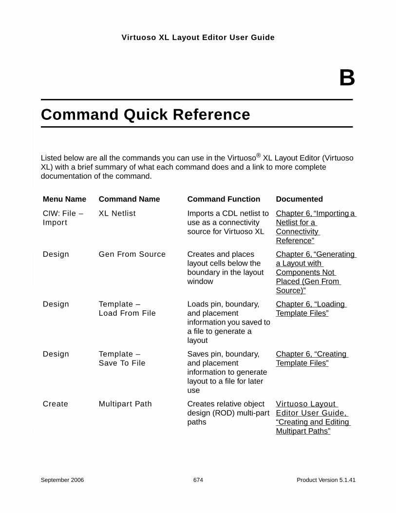
Virtuoso XL Layout Editor User Guide
BCommand Quick Reference
Listed below are all the commands you can use in the Virtuoso® XL Layout Editor (VirtuosoXL) with a brief summary of what each command does and a link to more completedocumentation of the command.
Menu Name Command Name Command Function Documented
CIW: File –Import
XL Netlist Imports a CDL netlist touse as a connectivitysource for Virtuoso XL
Chapter 6, “Importing aNetlist for aConnectivityReference”
Design Gen From Source Creates and placeslayout cells below theboundary in the layoutwindow
Chapter 6, “Generatinga Layout withComponents NotPlaced (Gen FromSource)”
Design Template –Load From File
Loads pin, boundary,and placementinformation you saved toa file to generate alayout
Chapter 6, “LoadingTemplate Files”
Design Template –Save To File
Saves pin, boundary,and placementinformation to generatelayout to a file for lateruse
Chapter 6, “CreatingTemplate Files”
Create Multipart Path Creates relative objectdesign (ROD) multi-partpaths
Virtuoso LayoutEditor User Guide,“Creating and EditingMultipart Paths”
September 2006 674 Product Version 5.1.41

Virtuoso XL Layout Editor User GuideCommand Quick Reference
Create Pick From Schematic Creates and placesinteractively selectedschematic elements inthe layout
Chapter 6, “MovingComponents from theSchematic into theLayout (Pick fromSchematic)”
Create Clone Copies parts ofschematic or layoutincluding connectivityinfo to use as other parts
Chapter 6, “Cloning”
Edit Other –Swap Components
Exchanges the positionof two components
Chapter 7, “SwappingComponents”
Edit Other –Lock Selected
Creates temporary fixedconstraints on layoutobjects
Chapter 7, “UsingDevice Locking”
Edit Other – UnlockSelected
Removes temporaryfixed constraints fromlayout objects
Chapter 7, “UsingDevice Locking”
Edit Component Types Controls howcomponents are placedin rows, and definestheir chaining andfolding parameters
Chapter 7,“Component Types”
Edit Transistor Chaining Abuts prepared MOStransistors into chains
Chapter 5, “DeviceAbutment,”
Edit Transistor Folding Splits prepared MOStransistors or chains intofingers (smaller devicesconnected in parallel).
Chapter 7, “UsingTransistor Folding”
Edit Place FromSchematic
Places componentsfrom the schematicinside the layoutboundary in the samerelative position as in theschematic
Chapter 6, “PlacingComponents in aLayout in the SameRelative Position as inthe Schematic (PlaceAs In Schematic)”
Menu Name Command Name Command Function Documented
September 2006 675 Product Version 5.1.41
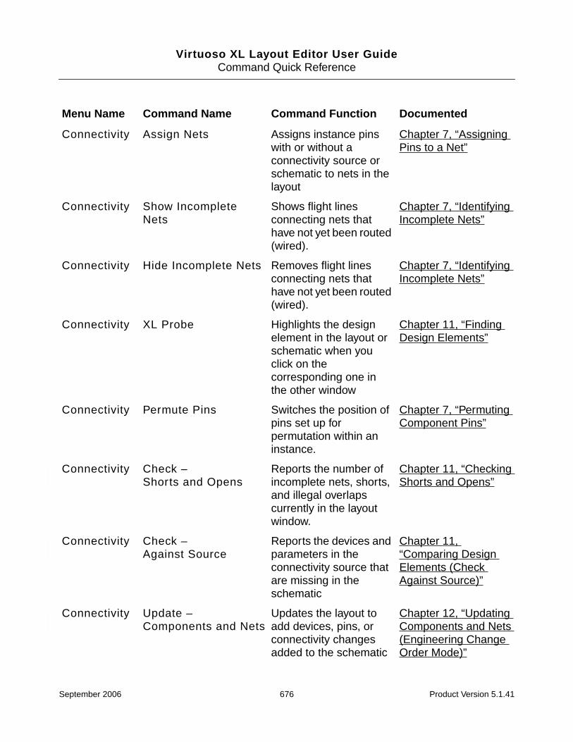
Virtuoso XL Layout Editor User GuideCommand Quick Reference
Connectivity Assign Nets Assigns instance pinswith or without aconnectivity source orschematic to nets in thelayout
Chapter 7, “AssigningPins to a Net”
Connectivity Show IncompleteNets
Shows flight linesconnecting nets thathave not yet been routed(wired).
Chapter 7, “IdentifyingIncomplete Nets”
Connectivity Hide Incomplete Nets Removes flight linesconnecting nets thathave not yet been routed(wired).
Chapter 7, “IdentifyingIncomplete Nets”
Connectivity XL Probe Highlights the designelement in the layout orschematic when youclick on thecorresponding one inthe other window
Chapter 11, “FindingDesign Elements”
Connectivity Permute Pins Switches the position ofpins set up forpermutation within aninstance.
Chapter 7, “PermutingComponent Pins”
Connectivity Check –Shorts and Opens
Reports the number ofincomplete nets, shorts,and illegal overlapscurrently in the layoutwindow.
Chapter 11, “CheckingShorts and Opens”
Connectivity Check –Against Source
Reports the devices andparameters in theconnectivity source thatare missing in theschematic
Chapter 11,“Comparing DesignElements (CheckAgainst Source)”
Connectivity Update –Components and Nets
Updates the layout toadd devices, pins, orconnectivity changesadded to the schematic
Chapter 12, “UpdatingComponents and Nets(Engineering ChangeOrder Mode)”
Menu Name Command Name Command Function Documented
September 2006 676 Product Version 5.1.41

Virtuoso XL Layout Editor User GuideCommand Quick Reference
Connectivity Update –Layout Parameters
Updates parameters ofinstances in the layout tomatch those in theschematic
Chapter 12, “UpdatingLayout Parameters”
Connectivity Update –SchematicParameters
Updates parameters ofdevices in the schematicto match those in thelayout
Chapter 12, “UpdatingSchematicParameters”
Connectivity Update –DeviceCorrespondence
Applies connectivityfrom schematicsymbol(s) to layoutdevice(s); allowsimplementation of oneor many to many or one
Chapter 12, “UpdatingDeviceCorrespondence”
Connectivity Update – Source Allows the connectivitysource for update to alayout to be a schematic,a netlist, or no source
Chapter 12, “Updatingthe ConnectivityReference”
Connectivity Change InstanceView
Changes the layout viewof a device or devices ina hierarchical design
Chapter 12, “Changingthe Device (Instance)View”
Options Layout XL Sets values of VirtuosoXL environmentvariables
Chapter 4, “SettingEnvironment Variables”
Menu Name Command Name Command Function Documented
September 2006 677 Product Version 5.1.41

Virtuoso XL Layout Editor User Guide
CUsing Spice and CDL for Netlist-DrivenLayout Generation
Introduction
The VXL Spice reader reads two styles of Spice, those being generic SPICE3 (Hspice-like)and CDL. Within these styles, only those constructs needed to support the netlist inputrequirements of VXL are read.
Specifying Spice Designs
A Spice design is specified to VXL via a single Spice netlist file. The cell defined at the filelevel (i.e., outside of any .SUBCKT block) is designated as the top level cell and is assignedthe name *TOP-CELL-(last part of file name). For example, for the Spice file /mycds/mydir/des_a.sp, the top level cell is assigned the name *TOP-CELL-des_a. All other cellsspecified in the design must be defined using the .SUBCKT or .MODEL statements. Someadditional cells may be created via an automatic mechanism as needed by the Spice reader.
The Spice netlist file can include other Spice netlists by using the .INCLUDE statement. Allcells defined within included files must be defined using the .SUBCKT or .MODELstatements. Further, all cell names in the design must be unique. The spice style (SPICE3 orCDL) must be specified to VXL.
Cell Creation Rules
Cells associated with a SUBCKT instance must be created using a .SUBCKT statement.
Cells associated with a mosfet, jfet, mesfet, BJT (bipolar), or diode instance can be createdone of 3 ways
1. By a .SUBCKT statement in which case the specified ports are used.
2. By a .MODEL statement.
September 2006 678 Product Version 5.1.41

Virtuoso XL Layout Editor User GuideUsing Spice and CDL for Netlist-Driven Layout Generation
a. Type nmos or pmos for a mosfet, in which case the ports D,G,S,B are used
b. Type njf or pjf for a jfet, in which case the ports D,G,S are used
c. Type nmf or pmf for a mesfet, in which case the ports D,G,S are used
d. Type npn or pnp for a BJT device, in which case the ports C,B,E are used
e. Type d for a diode, in which case the ports PLUS,MINUS are used
3. Automatically, by being an unresolved reference of a mosfet, jfet, mesfet, BJT, or diodeinstance in which case the ports D,G,S,B; D,G,S; D,G,S; C,B,D; or PLUS,MINUSrespectively are used.
Cells associated with a capacitor or resistor can be created in one of four ways
1. By a .SUBCKT statement in which case the specified ports are used.
2. By a .MODEL statement.
a. Type c for a capacitor, in which case the ports PLUS,MINUS are used
b. Type r for a resistor, in which case the ports PLUS,MINUS are used
3. Automatically, by being an unresolved reference of a capacitor or resistor instance, inwhich case the ports PLUS,MINUS are used.
4. Automatically, for cases where no model is specified, in which case the cell “-RES-” iscreated for a resistor and “-CAP-” is created for a capacitor. In both cases, the portsPLUS,MINUS are used.
Inductor references do not allow specification of a model. However, a default cell -IND- iscreated for all inductors. The ports PLUS,MINUS are used.
Voltage Source references do not allow specification of a model. However, a default cellnamed -VOLT- is created for all voltage sources. The ports PLUS, MINUS are used.
Note: The implications of the above are that references to mosfet, jfet, mesfet, BJT,capacitor, resistor, and diode models may be assumed but references to subckt cells arenever assumed.
September 2006 679 Product Version 5.1.41

Virtuoso XL Layout Editor User GuideUsing Spice and CDL for Netlist-Driven Layout Generation
Character Considerations
Case
In general case sensitivity is recognized, however the following rules and exceptions willapply
1. All keywords are treated as case insensitive.
2. The Scale parameter on the .OPTION line is treated as case insensitive.
3. On fet references, if implied width and length values are specified, uppercase W and Lare the assigned parameters.
The * Character
Spice
The * at the beginning of a column denotes the beginning of a comment which ends at theend of line. The * PORT statement is treated as a valid statement to determine port direction.
CDL
The * at the beginning of a column denotes the beginning of a comment which ends at theend of line. If this occurs before a command, then the command should be read by Draculabut not by the circuit simulator. For parsing CDL, thekeywords .GLOBAL, .INCLUDE, .OPTION, and .PARAM are processed even if a *precedes them.
The $ Character
Spice
Under most circumstances the $ denotes the beginning of a comment which ends at the endof line. The exceptions are when the $ is part (but not the start) of a name or when it is partof a quoted string. In these cases $ is treated as any other character.
September 2006 680 Product Version 5.1.41

Virtuoso XL Layout Editor User GuideUsing Spice and CDL for Netlist-Driven Layout Generation
CDL
The $ before a non-command field denotes that the following field should be read by Draculabut not circuit simulator. The $ before a command indicates that the line should be treated asa comment. For parsing CDL, any $ before a name field is ignored.
Characters in Names
Spice
A name may start with an alpha character or the following 3 characters % _ | . The allowablecharacters following the first character are alphanumeric, or the following seventeencharacters _ | + - [] < >.;: # $! *% /. However, the following three characters are strippedfrom the name < > /.
CDL
A name may start with an alpha character or the following four characters % _ | $ . Theallowable characters following the first character are alphanumeric, or the following twentyone characters _ | + - [] < >.;: # $! *% /, () ‘. However, the following fourteen characters arestripped from the name [] < >.; # $! /, () ‘.
Pin, Terminal, and Net Names
Pins, terminals, and nets are given additional naming latitude. In addition to the namesallowed by the general naming requirements under the Spice and CDL sections, pin, terminal,and net names are allowed to be a non-negative integer or a pair of non-negative integersseparated by a colon. Examples of such allowable names are 0, 17, and 4:2. Further, net 0is always treated as a global ground net.
Spice Statements
Conventions for Format Descriptions
{ } surround optional elements in a description of a syntax
| denotes OR
… denotes a list
September 2006 681 Product Version 5.1.41

Virtuoso XL Layout Editor User GuideUsing Spice and CDL for Netlist-Driven Layout Generation
numval represents a value which must be numeric (4, -2.2, 3.75U, -3.56e-7)
val represents a value which may be numeric, a (variable) parameter name or a literalstring enclosed in single quotes (4, -2.2, 3.75U, -3.56e-7, ppp, ‘anylit str’)
File Level Statements
First Line of File
The first line of a Spice or CDL file must be a comment.
Format (Spice or CDL) : *|$ {text}
* or $ is the comment character
text is an optional text string
Ex : * this is a Spice or CDL file
.GLOBAL
The.Global statement is used for specifying global nets.
Format (Spice or CDL) : .GLOBAL name{:P|G} …
name is the net name
P or G are optional and represents Power or Ground
Ex : .GLOBAL vdd:P vss:g GNETA
Note: CDL allows a * before the . of the .GLOBAL statement.
.INCLUDE
The .Include statement is used for including additional spice files from within a spice file.
The file included is treated similar to as if it were specified directly via command. There is noscoping done. However, all cells in an included file must be defined by .subckt or .modelstatements. If the specified file name supplied is not fully qualified, the run directory is usedas the base directory for the file.
Format (Spice or CDL) : .INCLUDE ‘filename’
filename is the file to be included
Ex : .INCLUDE ‘/cdsabc/mydir/sfile’
September 2006 682 Product Version 5.1.41
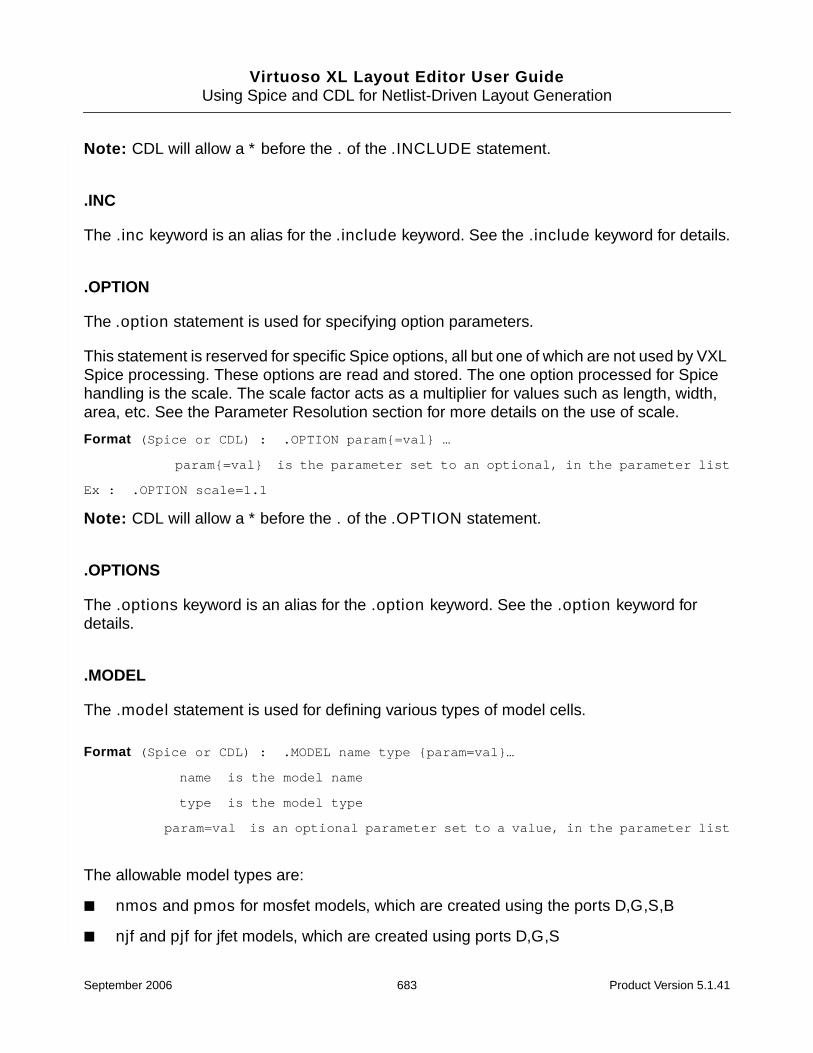
Virtuoso XL Layout Editor User GuideUsing Spice and CDL for Netlist-Driven Layout Generation
Note: CDL will allow a * before the . of the .INCLUDE statement.
.INC
The .inc keyword is an alias for the .include keyword. See the .include keyword for details.
.OPTION
The .option statement is used for specifying option parameters.
This statement is reserved for specific Spice options, all but one of which are not used by VXLSpice processing. These options are read and stored. The one option processed for Spicehandling is the scale. The scale factor acts as a multiplier for values such as length, width,area, etc. See the Parameter Resolution section for more details on the use of scale.
Format (Spice or CDL) : .OPTION param{=val} …
param{=val} is the parameter set to an optional, in the parameter list
Ex : .OPTION scale=1.1
Note: CDL will allow a * before the . of the .OPTION statement.
.OPTIONS
The .options keyword is an alias for the .option keyword. See the .option keyword fordetails.
.MODEL
The .model statement is used for defining various types of model cells.
Format (Spice or CDL) : .MODEL name type {param=val}…
name is the model name
type is the model type
param=val is an optional parameter set to a value, in the parameter list
The allowable model types are:
■ nmos and pmos for mosfet models, which are created using the ports D,G,S,B
■ njf and pjf for jfet models, which are created using ports D,G,S
September 2006 683 Product Version 5.1.41

Virtuoso XL Layout Editor User GuideUsing Spice and CDL for Netlist-Driven Layout Generation
■ nmf and pmf for mesfet models, which are created using ports D,G,S
■ npn and pnp for BJT (bipolar) models, which are created using the ports C,B,E
■ d for diode models, which are created using the ports PLUS,MINUS
■ c for capacitor models, which are created using the ports PLUS,MINUS
■ r for resistor models, which are created using the ports PLUS,MINUS
Ex: .MODEL TN nmos l = 1U w = 4U
.SUBCKT
The .subckt statement is used for defining subckt cells.
Format (Spice) : .SUBCKT name pin … {param=val}…
name is the cell name
pin is a pin in the pin list
param=val is an optional parameter set to a value, in the parameter list
Ex : .SUBCKT AND O A B L = 3U AS = 1.5P
Format (CDL) : .SUBCKT name {opin} … / {ipin} … {param=val}…
name is the cell name
opin is a pin in the output pin list
/ is the separator between the output pin list and the input pin list
ipin is a pin in the input pin list
param=val is an optional parameter set to a value, in the parameter list
Ex : .SUBCKT AND O / A B L = 3U AS = 1.5P
Note: For the CDL format, there must be at least one pin in the opin or the ipin list. For Spice,port types are specified using the *PORT statement.
.MACRO
The .macro keyword is an alias for the .subckt keyword. See the .subckt keyword fordetails.
.ENDS
The .ends statement is used for ending a .subcktcell definition.
September 2006 684 Product Version 5.1.41

Virtuoso XL Layout Editor User GuideUsing Spice and CDL for Netlist-Driven Layout Generation
Format (Spice or CDL) : .ENDS
.EOM
The .eom keyword is an alias for the .ends keyword. See the .ends keyword for details.
Statements Allowed at File Level or within a Subckt Cell or a Top Level Cell
.PARAM
The .param statement is used for specifying lists of parameters.
Format (Spice or CDL) : .PARAM param=val …
param=val is a parameter set to a value, in the parameter list
Ex : .PARAM w=5U p = wid str= ‘abc’
Note: CDL will allow a * before the . of the .PARAM statement.
Statements Allowed within a Subckt Cell or a Top Level Cell
* PORT
The * PORT statement is used for specifying pins as input or output pins.
Note: The *PORT statement is restricted to Spice only.
Format (Spice) : * PORT type pin …
type is the pin type and can take the values input, output, bidirecttristate, power, ground, supply, open_drain, or unknown pin is a pin in thepin list
Ex : * PORT input i1 i2
Note: For CDL, port types are specified on the .SUBCKT.
Subckt Reference
Format (Spice) : Xabc term … master {param=val}…
Xabc is the instance name
term is a terminal in the terminal list
master is the cell type (aka : master cell)
September 2006 685 Product Version 5.1.41
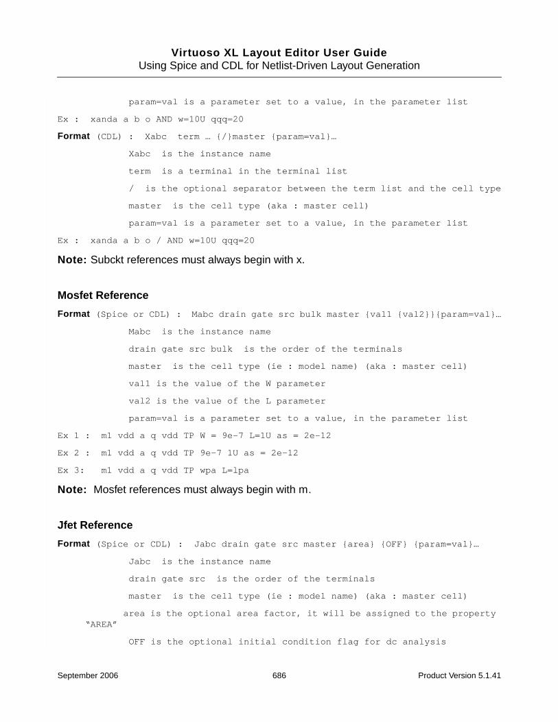
Virtuoso XL Layout Editor User GuideUsing Spice and CDL for Netlist-Driven Layout Generation
param=val is a parameter set to a value, in the parameter list
Ex : xanda a b o AND w=10U qqq=20
Format (CDL) : Xabc term … {/}master {param=val}…
Xabc is the instance name
term is a terminal in the terminal list
/ is the optional separator between the term list and the cell type
master is the cell type (aka : master cell)
param=val is a parameter set to a value, in the parameter list
Ex : xanda a b o / AND w=10U qqq=20
Note: Subckt references must always begin with x.
Mosfet Reference
Format (Spice or CDL) : Mabc drain gate src bulk master {val1 {val2}}{param=val}…
Mabc is the instance name
drain gate src bulk is the order of the terminals
master is the cell type (ie : model name) (aka : master cell)
val1 is the value of the W parameter
val2 is the value of the L parameter
param=val is a parameter set to a value, in the parameter list
Ex 1 : m1 vdd a q vdd TP W = 9e-7 L=1U as = 2e-12
Ex 2 : m1 vdd a q vdd TP 9e-7 1U as = 2e-12
Ex 3: m1 vdd a q vdd TP wpa L=lpa
Note: Mosfet references must always begin with m.
Jfet Reference
Format (Spice or CDL) : Jabc drain gate src master {area} {OFF} {param=val}…
Jabc is the instance name
drain gate src is the order of the terminals
master is the cell type (ie : model name) (aka : master cell)
area is the optional area factor, it will be assigned to the property“AREA”
OFF is the optional initial condition flag for dc analysis
September 2006 686 Product Version 5.1.41
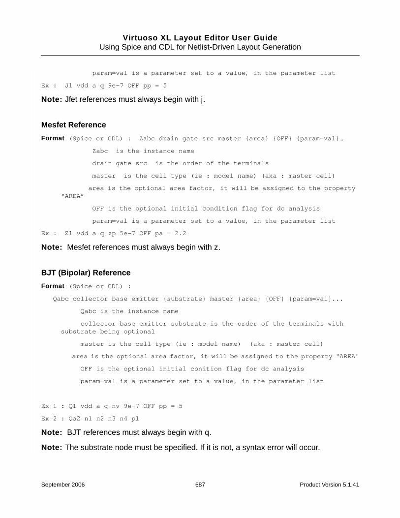
Virtuoso XL Layout Editor User GuideUsing Spice and CDL for Netlist-Driven Layout Generation
param=val is a parameter set to a value, in the parameter list
Ex : J1 vdd a q 9e-7 OFF pp = 5
Note: Jfet references must always begin with j.
Mesfet Reference
Format (Spice or CDL) : Zabc drain gate src master {area} {OFF} {param=val}…
Zabc is the instance name
drain gate src is the order of the terminals
master is the cell type (ie : model name) (aka : master cell)
area is the optional area factor, it will be assigned to the property“AREA”
OFF is the optional initial condition flag for dc analysis
param=val is a parameter set to a value, in the parameter list
Ex : Z1 vdd a q zp 5e-7 OFF pa = 2.2
Note: Mesfet references must always begin with z.
BJT (Bipolar) Reference
Format (Spice or CDL) :
Qabc collector base emitter {substrate} master {area} {OFF} {param=val}...
Qabc is the instance name
collector base emitter substrate is the order of the terminals withsubstrate being optional
master is the cell type (ie : model name) (aka : master cell)
area is the optional area factor, it will be assigned to the property "AREA"
OFF is the optional initial conition flag for dc analysis
param=val is a parameter set to a value, in the parameter list
Ex 1 : Q1 vdd a q nv 9e-7 OFF pp = 5
Ex 2 : Qa2 n1 n2 n3 n4 pl
Note: BJT references must always begin with q.
Note: The substrate node must be specified. If it is not, a syntax error will occur.
September 2006 687 Product Version 5.1.41
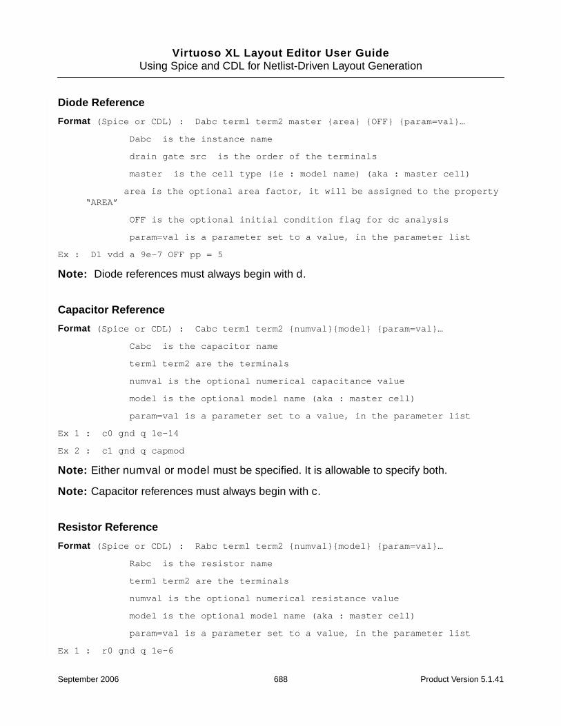
Virtuoso XL Layout Editor User GuideUsing Spice and CDL for Netlist-Driven Layout Generation
Diode Reference
Format (Spice or CDL) : Dabc term1 term2 master {area} {OFF} {param=val}…
Dabc is the instance name
drain gate src is the order of the terminals
master is the cell type (ie : model name) (aka : master cell)
area is the optional area factor, it will be assigned to the property“AREA”
OFF is the optional initial condition flag for dc analysis
param=val is a parameter set to a value, in the parameter list
Ex : D1 vdd a 9e-7 OFF pp = 5
Note: Diode references must always begin with d.
Capacitor Reference
Format (Spice or CDL) : Cabc term1 term2 {numval}{model} {param=val}…
Cabc is the capacitor name
term1 term2 are the terminals
numval is the optional numerical capacitance value
model is the optional model name (aka : master cell)
param=val is a parameter set to a value, in the parameter list
Ex 1 : c0 gnd q 1e-14
Ex 2 : c1 gnd q capmod
Note: Either numval or model must be specified. It is allowable to specify both.
Note: Capacitor references must always begin with c.
Resistor Reference
Format (Spice or CDL) : Rabc term1 term2 {numval}{model} {param=val}…
Rabc is the resistor name
term1 term2 are the terminals
numval is the optional numerical resistance value
model is the optional model name (aka : master cell)
param=val is a parameter set to a value, in the parameter list
Ex 1 : r0 gnd q 1e-6
September 2006 688 Product Version 5.1.41
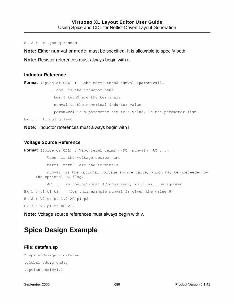
Virtuoso XL Layout Editor User GuideUsing Spice and CDL for Netlist-Driven Layout Generation
Ex 2 : r1 gnd q resmod
Note: Either numval or model must be specified. It is allowable to specify both.
Note: Resistor references must always begin with r.
Inductor Reference
Format (Spice or CDL) : Labc term1 term2 numval {param=val}…
Labc is the inductor name
term1 term2 are the terminals
numval is the numerical inductor value
param=val is a parameter set to a value, in the parameter list
Ex 1 : l1 gnd q 1e-6
Note: Inductor references must always begin with l.
Voltage Source Reference
Format (Spice or CDL) : Vabc term1 term2 <<DC> numval> <AC ...>
Vabc is the voltage source name
term1 term2 are the terminals
numval is the optional voltage source value, which may be preceeded bythe optional DC flag.
AC ... is the optional AC construct, which will be ignored
Ex 1 : v1 t1 t2 (for this example numval is given the value 0)
Ex 2 : V2 tt ss 1.0 AC p1 p2
Ex 3 : V3 pl mn DC 2.2
Note: Voltage source references must always begin with v.
Spice Design Example
File: datafan.sp
* spice design - datafan
.global vdd:p gnd:g
.option scale=1.1
September 2006 689 Product Version 5.1.41

Virtuoso XL Layout Editor User GuideUsing Spice and CDL for Netlist-Driven Layout Generation
.param ln=3u lp=4u wn=5u wp=6u
.include '/net/mycds/spice_files/latch.sp'
.include '/net/mycds/spice_files/models.sp'
.subckt MIV Q A
* port input A
* port output Q
m1 vdd A Q vdd TP W=7e-06 L=8e-06
m2 Q A gnd gnd TN 7e-06 8e-06
.ends
.subckt MND2 Q A B
* port input A
* port input B
* port output Q
m1 vdd A Q vdd TP W=wp L=lp
m2 vdd B Q vdd TP wn ln
m3 Q A temp gnd TN W=wpar L=lpar
m4 temp B gnd gnd TN wpar lpar
.ends
.subckt MNR2 Q A B
.param ln=7u lp=8u
* port input A B
* port output Q
m1 vdd A temp vdd TP W=wp L=lp
m2 temp B Q vdd TP wn ln
m3 Q A gnd gnd TN W=9u L=9u
m4 Q B gnd gnd TN 9u 9u
.ends
September 2006 690 Product Version 5.1.41

Virtuoso XL Layout Editor User GuideUsing Spice and CDL for Netlist-Driven Layout Generation
* top level
* port input I CLK E
* port output L1 L1N
* port output L2 L2N
* port output L3 L3N
Xinv1 D1 I MIV
Xnand1 Q1 D1 E MND2
Xinv2 Q2 Q1 MIV
Xinv3 DATA Q2 MIV
Xlatch1 L1 L1N DATA E CLK LATCH ln1=7.5u lp1=lp
+ wn1=wn wp1=wp wn2=8u wp2=wp
Xlatch2 L2 L2N DATA E CLK LATCH
Xlatch3 L3 L3N DATA E CLK LATCH
File: latch.sp
* latch
.GLOBAL vdd:P gnd:G
.OPTION scale=1.2
.PARAM ln=3.5U lp=4.5U wn=5.5U wp=6.5U
.SUBCKT LATCH Q QN D E CLK ln1=2.5U lp1=lp wn1=3.5U wp1=wp
.PARAM ln2=1.5U lp2=lp wn2=wn wp2=wp
* PORT input CLK
* PORT input D
* PORT input E
* PORT output Q
* PORT output QN
September 2006 691 Product Version 5.1.41

Virtuoso XL Layout Editor User GuideUsing Spice and CDL for Netlist-Driven Layout Generation
c1 gnd vdd 1.81369e-14
c2 gnd Q 1.37038e-14
c3 gnd QN 1.25655e-14
c4 gnd n8 1.2719e-14
c5 gnd n7 1.47611e-14
c6 gnd D 1.14232e-14
c7 gnd E 1.07987e-14
c8 gnd CLK 8.80052e-15
m9 Q QN gnd gnd TN W=1.5U L=2.5U
m10 gnd Q n10 gnd TN W=wn2 L=ln2
m11 n10 n7 QN gnd TN wn2 ln2
m12 n5 n8 QN gnd TN W=wn1 L=ln1
m13 gnd D n5 gnd TN wn1 ln1
m14 n1 CLK n7 gnd TN W=W L=L
m15 gnd E n1 gnd TN
m16 gnd n7 n8 gnd TN
m17 vdd QN Q vdd TP W=1.5U L=2.5U
m18 n9 Q vdd vdd TP W=wp2 L=lp2
m19 QN n8 n9 vdd TP wp2 lp2
m20 n4 n7 QN vdd TP W=wp1 L=lp1
m21 vdd D n4 vdd TP wp1 lp1
m22 vdd E n7 vdd TP W L
m23 vdd CLK n7 vdd TP
m24 n8 n7 vdd vdd TP
.ENDS
September 2006 692 Product Version 5.1.41
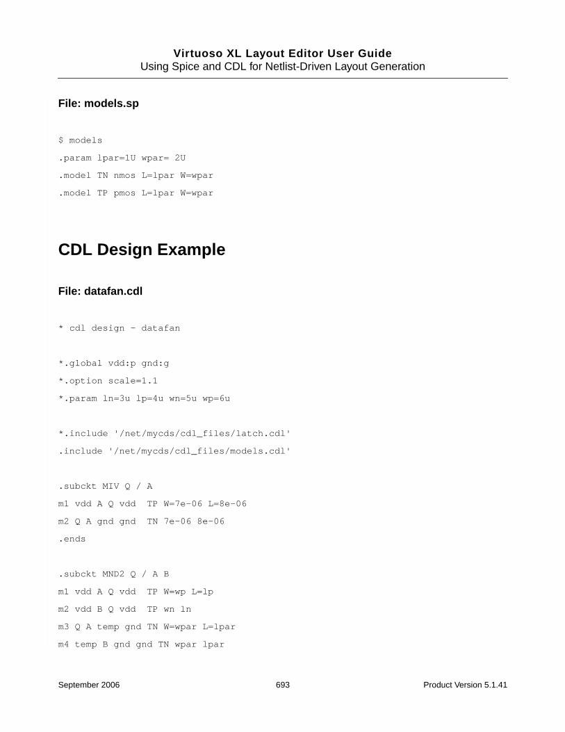
Virtuoso XL Layout Editor User GuideUsing Spice and CDL for Netlist-Driven Layout Generation
File: models.sp
$ models
.param lpar=1U wpar= 2U
.model TN nmos L=lpar W=wpar
.model TP pmos L=lpar W=wpar
CDL Design Example
File: datafan.cdl
* cdl design - datafan
*.global vdd:p gnd:g
*.option scale=1.1
*.param ln=3u lp=4u wn=5u wp=6u
*.include '/net/mycds/cdl_files/latch.cdl'
.include '/net/mycds/cdl_files/models.cdl'
.subckt MIV Q / A
m1 vdd A Q vdd TP W=7e-06 L=8e-06
m2 Q A gnd gnd TN 7e-06 8e-06
.ends
.subckt MND2 Q / A B
m1 vdd A Q vdd TP W=wp L=lp
m2 vdd B Q vdd TP wn ln
m3 Q A temp gnd TN W=wpar L=lpar
m4 temp B gnd gnd TN wpar lpar
September 2006 693 Product Version 5.1.41
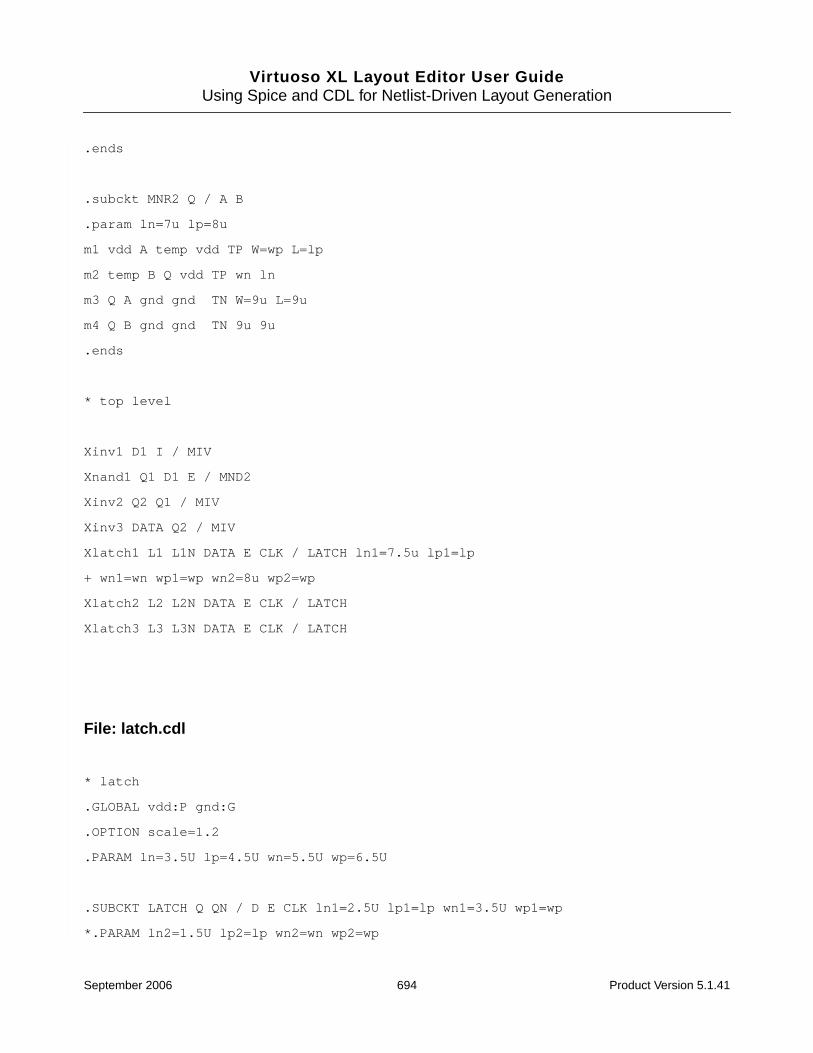
Virtuoso XL Layout Editor User GuideUsing Spice and CDL for Netlist-Driven Layout Generation
.ends
.subckt MNR2 Q / A B
.param ln=7u lp=8u
m1 vdd A temp vdd TP W=wp L=lp
m2 temp B Q vdd TP wn ln
m3 Q A gnd gnd TN W=9u L=9u
m4 Q B gnd gnd TN 9u 9u
.ends
* top level
Xinv1 D1 I / MIV
Xnand1 Q1 D1 E / MND2
Xinv2 Q2 Q1 / MIV
Xinv3 DATA Q2 / MIV
Xlatch1 L1 L1N DATA E CLK / LATCH ln1=7.5u lp1=lp
+ wn1=wn wp1=wp wn2=8u wp2=wp
Xlatch2 L2 L2N DATA E CLK / LATCH
Xlatch3 L3 L3N DATA E CLK / LATCH
File: latch.cdl
* latch
.GLOBAL vdd:P gnd:G
.OPTION scale=1.2
.PARAM ln=3.5U lp=4.5U wn=5.5U wp=6.5U
.SUBCKT LATCH Q QN / D E CLK ln1=2.5U lp1=lp wn1=3.5U wp1=wp
*.PARAM ln2=1.5U lp2=lp wn2=wn wp2=wp
September 2006 694 Product Version 5.1.41
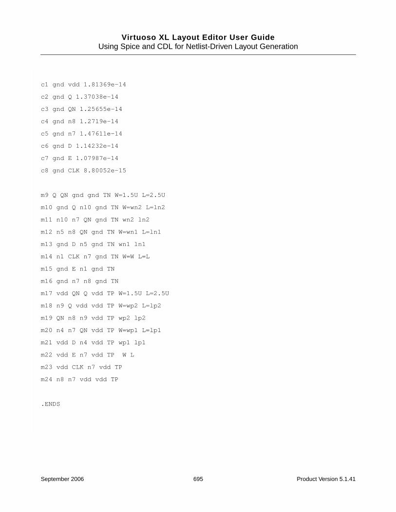
Virtuoso XL Layout Editor User GuideUsing Spice and CDL for Netlist-Driven Layout Generation
c1 gnd vdd 1.81369e-14
c2 gnd Q 1.37038e-14
c3 gnd QN 1.25655e-14
c4 gnd n8 1.2719e-14
c5 gnd n7 1.47611e-14
c6 gnd D 1.14232e-14
c7 gnd E 1.07987e-14
c8 gnd CLK 8.80052e-15
m9 Q QN gnd gnd TN W=1.5U L=2.5U
m10 gnd Q n10 gnd TN W=wn2 L=ln2
m11 n10 n7 QN gnd TN wn2 ln2
m12 n5 n8 QN gnd TN W=wn1 L=ln1
m13 gnd D n5 gnd TN wn1 ln1
m14 n1 CLK n7 gnd TN W=W L=L
m15 gnd E n1 gnd TN
m16 gnd n7 n8 gnd TN
m17 vdd QN Q vdd TP W=1.5U L=2.5U
m18 n9 Q vdd vdd TP W=wp2 L=lp2
m19 QN n8 n9 vdd TP wp2 lp2
m20 n4 n7 QN vdd TP W=wp1 L=lp1
m21 vdd D n4 vdd TP wp1 lp1
m22 vdd E n7 vdd TP W L
m23 vdd CLK n7 vdd TP
m24 n8 n7 vdd vdd TP
.ENDS
September 2006 695 Product Version 5.1.41
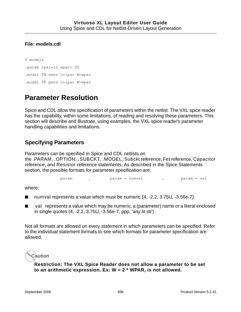
Virtuoso XL Layout Editor User GuideUsing Spice and CDL for Netlist-Driven Layout Generation
File: models.cdl
$ models
.param lpar=1U wpar= 2U
.model TN nmos L=lpar W=wpar
.model TP pmos L=lpar W=wpar
Parameter Resolution
Spice and CDL allow the specification of parameters within the netlist. The VXL spice readerhas the capability, within some limitations, of reading and resolving these parameters. Thissection will describe and illustrate, using examples, the VXL spice reader’s parameterhandling capabilities and limitations.
Specifying Parameters
Parameters can be specified in Spice and CDL netlists onthe .PARAM, .OPTION, .SUBCKT, .MODEL, Subckt reference, Fet reference, Capacitorreference, and Resistor reference statements. As described in the Spice Statementssection, the possible formats for parameter specification are;
param , param = numval , param = val
where;
■ numval represents a value which must be numeric (4, -2.2, 3.75U, -3.56e-7)
■ val represents a value which may be numeric, a (parameter) name or a literal enclosedin single quotes (4, -2.2, 3.75U, -3.56e-7, ppp, ‘any lit str’)
Not all formats are allowed on every statement in which parameters can be specified. Referto the individual statement formats to see which formats for parameter specification areallowed.
Caution
Restriction: The VXL Spice Reader does not allow a parameter to be setto an arithmetic expression. Ex: W = 2 * WPAR, is not allowed.
September 2006 696 Product Version 5.1.41

Virtuoso XL Layout Editor User GuideUsing Spice and CDL for Netlist-Driven Layout Generation
Parameter Levels
Every parameter specified in a netlist can be associated with a particular level of the netlist.The level of a parameter is determined by the where it is defined within the netlist. There arethree possible levels, those being, from highest to lowest, file, cell, and instance.
Parameters defined on the .OPTION statement are file level parameters. Parametersdefined on the .PARAM statement outside of subckts are also file level. Parameters definedon the .PARAM statement within a subckt are cell level parameters. Parameters defined onthe .SUBCKT or the .MODEL statement are also cell level. Parameters defined on Subcktreference, Fet reference, Capacitor reference, or Resistor reference statements areinstance level parameters.
Parameter levels are an important consideration for parameter resolution.
Resolving Parameters
The VXL Spice Reader contains a resolver that resolves parameters to values. Resolution isbased on a set of rules that take into account the value type of the parameter, the level of theparameter, and possibly the scale factor. Scaling is discussed in the Scaling Parameterssection.
Literal string parameters are fully resolved as specified. Numerical parameters are alsoresolved as specified, except that they may need to be scaled by a scale factor. Variableparameters are resolved by various rules that are described below.
Rule 1: The first basic rule for variable parameter resolution is to look, at the next parameterlevel up, for the parameter of the variable name specified by the parameter being resolved.
For example, when attempting to resolve the parameter W which was specified as W =wpar, the resolver will look for the parameter wpar at the next parameter level up. So,for example, if wpar = 6U at the next higher level, then W will resolve to the value 6U.
Restriction: The implication of this rule is that the resolver will not look at the same levelto resolve a parameter.
For example, if in the specification of a particular instance, the parameters W = wparand wpar = 4U are specified, the resolver will not resolve W to the value 4U.
File level variable parameters are considered resolved to their variable (string) value,since there is nowhere else to look to try to resolve them. For example, at the file level,the parameter W = wpar, W will resolve to the string wpar.
September 2006 697 Product Version 5.1.41

Virtuoso XL Layout Editor User GuideUsing Spice and CDL for Netlist-Driven Layout Generation
Cell level variable parameters can be resolved only by using the file level parameters ofthe file in which the cell resides. If the variable parameter value cannot be found as aparameter at the file level, then the cell level parameter is considered resolved. Forexample, at the cell level, are the parameters W1 = wp1, W2 = wp2, and W3 = wp3and, at the file level, are the parameters wp1 = 4U and wp2 = wstr. W1 will resolve to4U, W2 will resolve to the string wstr, and W3 will resolve to the string wp3.
The situation for instance level variable parameters is more complex than that ofparameters at the file or cell level. This is because Spice and CDL allow parameters tobe passed into an instance from the instance above it in the instance tree. Further,instance level parameters can be inherited from the master cell of the instance.
If a parameter exists on the master cell of an instance, but that parameter does exist onthe instance itself, then the instance inherits that parameter from the master cell. Forexample, an instance does not contain the parameter W but the master cell for thatinstances specifies, W = 4U, then the instance inherits the W parameter and the value4U is assigned to it.
Parameter passing plays a large role in variable parameter resolution for instances.The resolver follows certain rules for parameter passing.
Rule 2: Only parameters specified on the cell definition line (.SUBCKT or .MODEL line) ofthe cell in which an instance resides, can be passed into an instance.
For example, for instance Xi1 of the cell named excel defined below,
.SUBCKT excel I O wp1 = 5U
.PARAM wp2 = 6U
Xi1 I A inv W1 = wp1 W2 = wp2
A value for wp1 may be passed into Xi1 but a value for wp2 cannot. This is because wp1is specified on the .SUBKCT line but wp2 is not.
Rule 3: The order of priority for variable parameter searching during resolution is
1. Parameters passed via instance.
2. Cell level parameters.
3. File level parameters.
4. Parameters from the master of the instance.
September 2006 698 Product Version 5.1.41

Virtuoso XL Layout Editor User GuideUsing Spice and CDL for Netlist-Driven Layout Generation
Sample Rules
The following Spice netlist example is used to illustrate various cases of parameter resolution.Results for all possible instance tree combinations down to the fet level can be found in theComplete ibuf Example Results section.
File: IBUF.SP
.GLOBAL vdd gnd
.option scale=1.0
.param PPP=600U W=400U L=400.5U P1=401U P2=402U P3=403U P4=404U P5=405U
.include '/net/mycds/spice_files/IBUF_I.SP'
.subckt IBUFTWO I O W=200U L=200.5U P1=201U P2=202U P4=204U
.param P3=203U PP3=213U
*port input I
*port output O
Xinv1 I A MIV W=100U L=L P1=101U P2=102U P4=104U
Xinv2 A B MIV W=P1 WW=105U
Xinv3 B C MIV P5=PPP
Xinv4 C O MIV P1=W P4=WW
.ends
* top level
*port input II
*port output OO
Xibuf1 II AA IBUFTWO W=300U P1=P3
Xibuf2 AA BB IBUFTWO W=P1 L=P4
Xibuf3 BB OO IBUFTWO L=PP3
File: IBUF_I.SP
*
September 2006 699 Product Version 5.1.41

Virtuoso XL Layout Editor User GuideUsing Spice and CDL for Netlist-Driven Layout Generation
.GLOBAL vdd:P gnd:G
.option scale = 1.0
.param P4=20U P5=25U PP1=21U PP2=22U PP3=23U
.model TN nmos level=2 L=1.0U W=2.0U WW=3U PP4=34U
.model TP pmos W=2.5U L=1.5U level=2 WW=4U
.subckt MIV A Q L=4.0U W=5.0U P1=6.0U P2=7.0U P3=8U P4=9U P5=PP1
.param WW=30U LL=31U PP3=32U
* port input A
* port output Q
m1 vdd A B vdd TP W=9e-07 L=1e-06
m2 B A gnd gnd TN 3.0U 2.0U
m3 vdd B C vdd TP W L
m4 C B gnd gnd TN W=P1 L=P2
m5 vdd C D vdd TP WW L=P3
m6 D C gnd gnd TN W=WW L=P4
m7 vdd D E vdd TP L=P5 W=PP2
m8 E D gnd gnd TN
m9 vdd E Q vdd TP W=WW L=LL
m10 Q E gnd gnd TN W=PP3 L=PP4
.ends
Ex 1 : InstTree = Xibuf1@IBUF / Xinv1@IBUFTWO / m1@MIV
Parameter = W
Value = 9e-7
Reason : W is set to the value 9e-7. Note that for all instance trees ending m1@MIV,will take on the value 9e-7.
September 2006 700 Product Version 5.1.41

Virtuoso XL Layout Editor User GuideUsing Spice and CDL for Netlist-Driven Layout Generation
Ex 2 : InstTree = Xibuf1@IBUF / Xinv1@IBUFTWO / m2@MIV
Parameter = L
Value = 2.0U
Reason : Fet m2, employs implied parameters. The first corresponds to W and thesecond to L. Here L set to 2.0U. For all instance trees ending at m2@MIV, Lwill take on the value 2.0U
Ex 3 : InstTree = Xibuf1@IBUF / Xinv1@IBUFTWO / m4@MIV
Parameter = W
Value = 101U
Reason : Fet m4, specifies W = P1 Since P1 is specified on the .SUBCKT line ofMIV, it can be passed into m4. Xinv1, the instance above m4, in the instancespecifies P1 = 101U.
Ex 4 : InstTree = Xibuf1@IBUF / Xinv1@IBUFTWO / m3@MIV
Parameter = W
Value = 100U
Reason : Fet m3, employs implied parameters. The first corresponds to W, resultingin W = W. Since W is specified on the .SUBCKT line of MIV, it can be passedinto m3. Xinv1 specifies W = 100U.
Ex 5 : InstTree = Xibuf1@IBUF / Xinv1@IBUFTWO / m5@MIV
Parameter = L
Value = 8U
Reason : Fet m5, specifies L = P3. Since P3 is specified on the .SUBCKT line ofMIV, it can be passed into m5. However, Xinv1 doesn’t specify P3. So the valuefor P3 is 8U, being obtained from the cell level specification in MIV.
September 2006 701 Product Version 5.1.41

Virtuoso XL Layout Editor User GuideUsing Spice and CDL for Netlist-Driven Layout Generation
Ex 6 : InstTree = Xibuf1@IBUF / Xinv2@IBUFTWO / m6@MIV
Parameter = W
Value = 30U
Reason : Fet m5 specifies W = WW. Since WW is not specified on the .SUBCKT lineof MIV, it cannot be passed into m6. So the value for WW is 30U, being obtainedfrom the cell level specification in MIV.
Ex 7 : InstTree = Xibuf1@IBUF / Xinv4@IBUFTWO / m4@MIV
Parameter = W
Value = 300U
Reason : Fet m4 specifies W = P1. Since P1 is on the .SUBCKT line of MIV, it canbe passed in from Xinv4. Xinv4 specifies P1 = W. Since W is on the .SUBCKTline of IBUFTWO, it can be passed into xinv4. Xibuf1 specifies W = 300U.
Ex 8 : InstTree = Xibuf2@IBUF / Xinv3@IBUFTWO / m7@MIV
Parameter = L
Value = 600U
Reason : Fet m7 specifies L = P5. P5 can be passed into m7. Xinv3 specifies P5 =PPP. PPP cannot be passed into Xinv3. Further, PPP is not at the cell levelfor Xinv3 because it was not specified on the .SUBCKT IBUF2 nor in the .PARAMstatement inside IBUFTWO. However, PPP can be found at the file level forXinv3, being specified on the .PARAM statement of the file in which Xinv3resides. Thus PPP = 600U.
Ex 9 : InstTree = Xibuf1@IBUF / Xinv4@IBUFTWO / m10@MIV
Parameter = L
Value = 34U
September 2006 702 Product Version 5.1.41
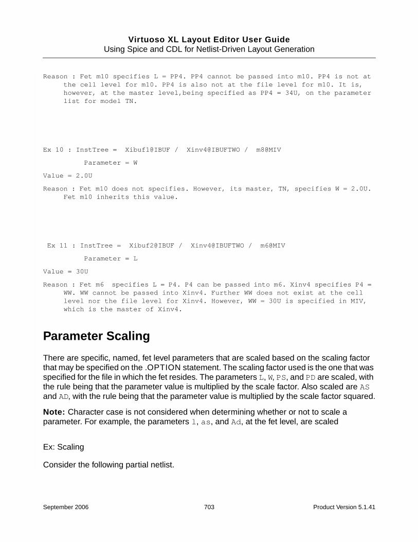
Virtuoso XL Layout Editor User GuideUsing Spice and CDL for Netlist-Driven Layout Generation
Reason : Fet m10 specifies L = PP4. PP4 cannot be passed into m10. PP4 is not atthe cell level for m10. PP4 is also not at the file level for m10. It is,however, at the master level,being specified as PP4 = 34U, on the parameterlist for model TN.
Ex 10 : InstTree = Xibuf1@IBUF / Xinv4@IBUFTWO / m8@MIV
Parameter = W
Value = 2.0U
Reason : Fet m10 does not specifies. However, its master, TN, specifies W = 2.0U.Fet m10 inherits this value.
Ex 11 : InstTree = Xibuf2@IBUF / Xinv4@IBUFTWO / m6@MIV
Parameter = L
Value = 30U
Reason : Fet m6 specifies L = P4. P4 can be passed into m6. Xinv4 specifies P4 =WW. WW cannot be passed into Xinv4. Further WW does not exist at the celllevel nor the file level for Xinv4. However, WW = 30U is specified in MIV,which is the master of Xinv4.
Parameter Scaling
There are specific, named, fet level parameters that are scaled based on the scaling factorthat may be specified on the .OPTION statement. The scaling factor used is the one that wasspecified for the file in which the fet resides. The parameters L, W, PS, and PD are scaled, withthe rule being that the parameter value is multiplied by the scale factor. Also scaled are ASand AD, with the rule being that the parameter value is multiplied by the scale factor squared.
Note: Character case is not considered when determining whether or not to scale aparameter. For example, the parameters l, as, and Ad, at the fet level, are scaled
Ex: Scaling
Consider the following partial netlist.
September 2006 703 Product Version 5.1.41
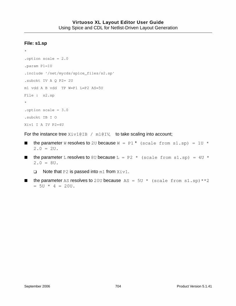
Virtuoso XL Layout Editor User GuideUsing Spice and CDL for Netlist-Driven Layout Generation
File: s1.sp
*
.option scale = 2.0
.param P1=1U
.include '/net/mycds/spice_files/s2.sp'
.subckt IV A Q P2= 2U
m1 vdd A B vdd TP W=P1 L=P2 AS=5U
File : s2.sp
*
.option scale = 3.0
.subckt IB I O
Xiv1 I A IV P2=4U
For the instance tree Xiv1@IB / m1@IV, to take scaling into account;
■ the parameter W resolves to 2U because W = P1 * (scale from s1.sp) = 1U *2.0 = 2U.
■ the parameter L resolves to 8U because L = P2 * (scale from s1.sp) = 4U *2.0 = 8U.
❑ Note that P2 is passed into m1 from Xiv1.
■ the parameter AS resolves to 20U because AS = 5U * (scale from s1.sp)**2= 5U * 4 = 20U.
September 2006 704 Product Version 5.1.41

Virtuoso XL Layout Editor User GuideUsing Spice and CDL for Netlist-Driven Layout Generation
Complete ibuf Example ResultsInstTree = Xibuf1@IBUF / Xinv1@IBUFTWO / m1@MIV
Parameter = W
Value = 9.000000e-07
Parameter = L
Value = 1.000000e-06
InstTree = Xibuf1@IBUF / Xinv1@IBUFTWO / m2@MIV
Parameter = W
Value = 3.000000e-06
Parameter = L
Value = 2.000000e-06
InstTree = Xibuf1@IBUF / Xinv1@IBUFTWO / m3@MIV
Parameter = W
Value = 1.000000e-04
Parameter = L
Value = 2.005000e-04
InstTree = Xibuf1@IBUF / Xinv1@IBUFTWO / m4@MIV
Parameter = W
Value = 1.010000e-04
Parameter = L
Value = 1.020000e-04
InstTree = Xibuf1@IBUF / Xinv1@IBUFTWO / m5@MIV
Parameter = W
Value = 3.000000e-05
Parameter = L
Value = 8.000000e-06
InstTree = Xibuf1@IBUF / Xinv1@IBUFTWO / m6@MIV
September 2006 705 Product Version 5.1.41

Virtuoso XL Layout Editor User GuideUsing Spice and CDL for Netlist-Driven Layout Generation
Parameter = W
Value = 3.000000e-05
Parameter = L
Value = 1.040000e-04
InstTree = Xibuf1@IBUF / Xinv1@IBUFTWO / m7@MIV
Parameter = W
Value = 2.200000e-05
Parameter = L
Value = 2.100000e-05
InstTree = Xibuf1@IBUF / Xinv1@IBUFTWO / m8@MIV
Parameter = W
Value = 2.000000e-06
Parameter = L
Value = 1.000000e-06
InstTree = Xibuf1@IBUF / Xinv1@IBUFTWO / m9@MIV
Parameter = W
Value = 3.000000e-05
Parameter = L
Value = 3.100000e-05
InstTree = Xibuf1@IBUF / Xinv1@IBUFTWO / m10@MIV
Parameter = W
Value = 3.200000e-05
Parameter = L
Value = 3.400000e-05
InstTree = Xibuf1@IBUF / Xinv2@IBUFTWO / m1@MIV
Parameter = W
Value = 9.000000e-07
September 2006 706 Product Version 5.1.41

Virtuoso XL Layout Editor User GuideUsing Spice and CDL for Netlist-Driven Layout Generation
Parameter = L
Value = 1.000000e-06
InstTree = Xibuf1@IBUF / Xinv2@IBUFTWO / m2@MIV
Parameter = W
Value = 3.000000e-06
Parameter = L
Value = 2.000000e-06
InstTree = Xibuf1@IBUF / Xinv2@IBUFTWO / m3@MIV
Parameter = W
Value = 4.030000e-04
Parameter = L
Value = 4.000000e-06
InstTree = Xibuf1@IBUF / Xinv2@IBUFTWO / m4@MIV
Parameter = W
Value = 6.000000e-06
Parameter = L
Value = 7.000000e-06
InstTree = Xibuf1@IBUF / Xinv2@IBUFTWO / m5@MIV
Parameter = W
Value = 3.000000e-05
Parameter = L
Value = 8.000000e-06
InstTree = Xibuf1@IBUF / Xinv2@IBUFTWO / m6@MIV
Parameter = W
Value = 3.000000e-05
Parameter = L
Value = 9.000000e-06
September 2006 707 Product Version 5.1.41

Virtuoso XL Layout Editor User GuideUsing Spice and CDL for Netlist-Driven Layout Generation
InstTree = Xibuf1@IBUF / Xinv2@IBUFTWO / m7@MIV
Parameter = W
Value = 2.200000e-05
Parameter = L
Value = 2.100000e-05
InstTree = Xibuf1@IBUF / Xinv2@IBUFTWO / m8@MIV
Parameter = W
Value = 2.000000e-06
Parameter = L
Value = 1.000000e-06
InstTree = Xibuf1@IBUF / Xinv2@IBUFTWO / m9@MIV
Parameter = W
Value = 3.000000e-05
Parameter = L
Value = 3.100000e-05
InstTree = Xibuf1@IBUF / Xinv2@IBUFTWO / m10@MIV
Parameter = W
Value = 3.200000e-05
Parameter = L
Value = 3.400000e-05
InstTree = Xibuf1@IBUF / Xinv3@IBUFTWO / m1@MIV
Parameter = W
Value = 9.000000e-07
Parameter = L
Value = 1.000000e-06
InstTree = Xibuf1@IBUF / Xinv3@IBUFTWO / m2@MIV
Parameter = W
September 2006 708 Product Version 5.1.41

Virtuoso XL Layout Editor User GuideUsing Spice and CDL for Netlist-Driven Layout Generation
Value = 3.000000e-06
Parameter = L
Value = 2.000000e-06
InstTree = Xibuf1@IBUF / Xinv3@IBUFTWO / m3@MIV
Parameter = W
Value = 5.000000e-06
Parameter = L
Value = 4.000000e-06
InstTree = Xibuf1@IBUF / Xinv3@IBUFTWO / m4@MIV
Parameter = W
Value = 6.000000e-06
Parameter = L
Value = 7.000000e-06
InstTree = Xibuf1@IBUF / Xinv3@IBUFTWO / m5@MIV
Parameter = W
Value = 3.000000e-05
Parameter = L
Value = 8.000000e-06
InstTree = Xibuf1@IBUF / Xinv3@IBUFTWO / m6@MIV
Parameter = W
Value = 3.000000e-05
Parameter = L
Value = 9.000000e-06
InstTree = Xibuf1@IBUF / Xinv3@IBUFTWO / m7@MIV
Parameter = W
Value = 2.200000e-05
Parameter = L
Value = 6.000000e-04
September 2006 709 Product Version 5.1.41

Virtuoso XL Layout Editor User GuideUsing Spice and CDL for Netlist-Driven Layout Generation
InstTree = Xibuf1@IBUF / Xinv3@IBUFTWO / m8@MIV
Parameter = W
Value = 2.000000e-06
Parameter = L
Value = 1.000000e-06
InstTree = Xibuf1@IBUF / Xinv3@IBUFTWO / m9@MIV
Parameter = W
Value = 3.000000e-05
Parameter = L
Value = 3.100000e-05
InstTree = Xibuf1@IBUF / Xinv3@IBUFTWO / m10@MIV
Parameter = W
Value = 3.200000e-05
Parameter = L
Value = 3.400000e-05
InstTree = Xibuf1@IBUF / Xinv4@IBUFTWO / m1@MIV
Parameter = W
Value = 9.000000e-07
Parameter = L
Value = 1.000000e-06
InstTree = Xibuf1@IBUF / Xinv4@IBUFTWO / m2@MIV
Parameter = W
Value = 3.000000e-06
Parameter = L
Value = 2.000000e-06
InstTree = Xibuf1@IBUF / Xinv4@IBUFTWO / m3@MIV
Parameter = W
September 2006 710 Product Version 5.1.41

Virtuoso XL Layout Editor User GuideUsing Spice and CDL for Netlist-Driven Layout Generation
Value = 5.000000e-06
Parameter = L
Value = 4.000000e-06
InstTree = Xibuf1@IBUF / Xinv4@IBUFTWO / m4@MIV
Parameter = W
Value = 3.000000e-04
Parameter = L
Value = 7.000000e-06
InstTree = Xibuf1@IBUF / Xinv4@IBUFTWO / m5@MIV
Parameter = W
Value = 3.000000e-05
Parameter = L
Value = 8.000000e-06
InstTree = Xibuf1@IBUF / Xinv4@IBUFTWO / m6@MIV
Parameter = W
Value = 3.000000e-05
Parameter = L
Value = 3.000000e-05
InstTree = Xibuf1@IBUF / Xinv4@IBUFTWO / m7@MIV
Parameter = W
Value = 2.200000e-05
Parameter = L
Value = 2.100000e-05
InstTree = Xibuf1@IBUF / Xinv4@IBUFTWO / m8@MIV
Parameter = W
Value = 2.000000e-06
Parameter = L
Value = 1.000000e-06
September 2006 711 Product Version 5.1.41

Virtuoso XL Layout Editor User GuideUsing Spice and CDL for Netlist-Driven Layout Generation
InstTree = Xibuf1@IBUF / Xinv4@IBUFTWO / m9@MIV
Parameter = W
Value = 3.000000e-05
Parameter = L
Value = 3.100000e-05
InstTree = Xibuf1@IBUF / Xinv4@IBUFTWO / m10@MIV
Parameter = W
Value = 3.200000e-05
Parameter = L
Value = 3.400000e-05
InstTree = Xibuf2@IBUF / Xinv1@IBUFTWO / m1@MIV
Parameter = W
Value = 9.000000e-07
Parameter = L
Value = 1.000000e-06
InstTree = Xibuf2@IBUF / Xinv1@IBUFTWO / m2@MIV
Parameter = W
Value = 3.000000e-06
Parameter = L
Value = 2.000000e-06
InstTree = Xibuf2@IBUF / Xinv1@IBUFTWO / m3@MIV
Parameter = W
Value = 1.000000e-04
Parameter = L
Value = 4.040000e-04
InstTree = Xibuf2@IBUF / Xinv1@IBUFTWO / m4@MIV
Parameter = W
September 2006 712 Product Version 5.1.41

Virtuoso XL Layout Editor User GuideUsing Spice and CDL for Netlist-Driven Layout Generation
Value = 1.010000e-04
Parameter = L
Value = 1.020000e-04
InstTree = Xibuf2@IBUF / Xinv1@IBUFTWO / m5@MIV
Parameter = W
Value = 3.000000e-05
Parameter = L
Value = 8.000000e-06
InstTree = Xibuf2@IBUF / Xinv1@IBUFTWO / m6@MIV
Parameter = W
Value = 3.000000e-05
Parameter = L
Value = 1.040000e-04
InstTree = Xibuf2@IBUF / Xinv1@IBUFTWO / m7@MIV
Parameter = W
Value = 2.200000e-05
Parameter = L
Value = 2.100000e-05
InstTree = Xibuf2@IBUF / Xinv1@IBUFTWO / m8@MIV
Parameter = W
Value = 2.000000e-06
Parameter = L
Value = 1.000000e-06
InstTree = Xibuf2@IBUF / Xinv1@IBUFTWO / m9@MIV
Parameter = W
Value = 3.000000e-05
Parameter = L
September 2006 713 Product Version 5.1.41
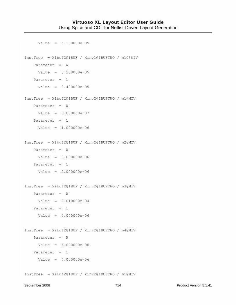
Virtuoso XL Layout Editor User GuideUsing Spice and CDL for Netlist-Driven Layout Generation
Value = 3.100000e-05
InstTree = Xibuf2@IBUF / Xinv1@IBUFTWO / m10@MIV
Parameter = W
Value = 3.200000e-05
Parameter = L
Value = 3.400000e-05
InstTree = Xibuf2@IBUF / Xinv2@IBUFTWO / m1@MIV
Parameter = W
Value = 9.000000e-07
Parameter = L
Value = 1.000000e-06
InstTree = Xibuf2@IBUF / Xinv2@IBUFTWO / m2@MIV
Parameter = W
Value = 3.000000e-06
Parameter = L
Value = 2.000000e-06
InstTree = Xibuf2@IBUF / Xinv2@IBUFTWO / m3@MIV
Parameter = W
Value = 2.010000e-04
Parameter = L
Value = 4.000000e-06
InstTree = Xibuf2@IBUF / Xinv2@IBUFTWO / m4@MIV
Parameter = W
Value = 6.000000e-06
Parameter = L
Value = 7.000000e-06
InstTree = Xibuf2@IBUF / Xinv2@IBUFTWO / m5@MIV
September 2006 714 Product Version 5.1.41

Virtuoso XL Layout Editor User GuideUsing Spice and CDL for Netlist-Driven Layout Generation
Parameter = W
Value = 3.000000e-05
Parameter = L
Value = 8.000000e-06
InstTree = Xibuf2@IBUF / Xinv2@IBUFTWO / m6@MIV
Parameter = W
Value = 3.000000e-05
Parameter = L
Value = 9.000000e-06
InstTree = Xibuf2@IBUF / Xinv2@IBUFTWO / m7@MIV
Parameter = W
Value = 2.200000e-05
Parameter = L
Value = 2.100000e-05
InstTree = Xibuf2@IBUF / Xinv2@IBUFTWO / m8@MIV
Parameter = W
Value = 2.000000e-06
Parameter = L
Value = 1.000000e-06
InstTree = Xibuf2@IBUF / Xinv2@IBUFTWO / m9@MIV
Parameter = W
Value = 3.000000e-05
Parameter = L
Value = 3.100000e-05
InstTree = Xibuf2@IBUF / Xinv2@IBUFTWO / m10@MIV
Parameter = W
Value = 3.200000e-05
Parameter = L
September 2006 715 Product Version 5.1.41

Virtuoso XL Layout Editor User GuideUsing Spice and CDL for Netlist-Driven Layout Generation
Value = 3.400000e-05
InstTree = Xibuf2@IBUF / Xinv3@IBUFTWO / m1@MIV
Parameter = W
Value = 9.000000e-07
Parameter = L
Value = 1.000000e-06
InstTree = Xibuf2@IBUF / Xinv3@IBUFTWO / m2@MIV
Parameter = W
Value = 3.000000e-06
Parameter = L
Value = 2.000000e-06
InstTree = Xibuf2@IBUF / Xinv3@IBUFTWO / m3@MIV
Parameter = W
Value = 5.000000e-06
Parameter = L
Value = 4.000000e-06
InstTree = Xibuf2@IBUF / Xinv3@IBUFTWO / m4@MIV
Parameter = W
Value = 6.000000e-06
Parameter = L
Value = 7.000000e-06
InstTree = Xibuf2@IBUF / Xinv3@IBUFTWO / m5@MIV
Parameter = W
Value = 3.000000e-05
Parameter = L
Value = 8.000000e-06
September 2006 716 Product Version 5.1.41
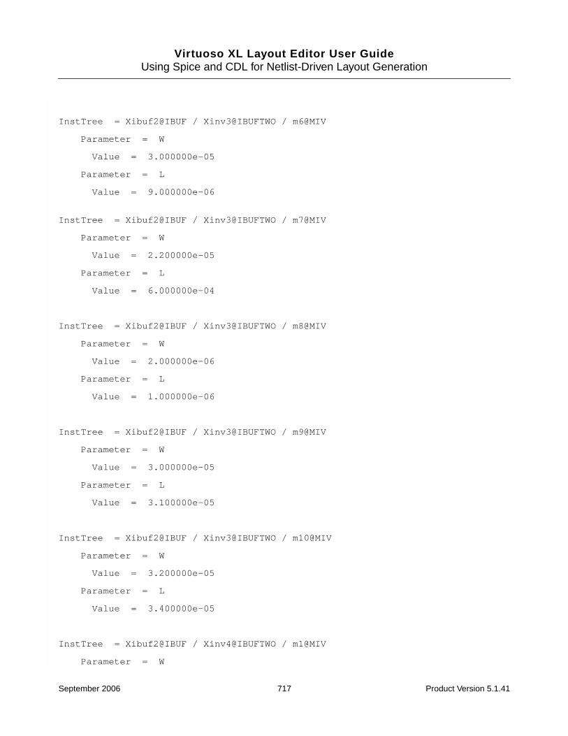
Virtuoso XL Layout Editor User GuideUsing Spice and CDL for Netlist-Driven Layout Generation
InstTree = Xibuf2@IBUF / Xinv3@IBUFTWO / m6@MIV
Parameter = W
Value = 3.000000e-05
Parameter = L
Value = 9.000000e-06
InstTree = Xibuf2@IBUF / Xinv3@IBUFTWO / m7@MIV
Parameter = W
Value = 2.200000e-05
Parameter = L
Value = 6.000000e-04
InstTree = Xibuf2@IBUF / Xinv3@IBUFTWO / m8@MIV
Parameter = W
Value = 2.000000e-06
Parameter = L
Value = 1.000000e-06
InstTree = Xibuf2@IBUF / Xinv3@IBUFTWO / m9@MIV
Parameter = W
Value = 3.000000e-05
Parameter = L
Value = 3.100000e-05
InstTree = Xibuf2@IBUF / Xinv3@IBUFTWO / m10@MIV
Parameter = W
Value = 3.200000e-05
Parameter = L
Value = 3.400000e-05
InstTree = Xibuf2@IBUF / Xinv4@IBUFTWO / m1@MIV
Parameter = W
September 2006 717 Product Version 5.1.41

Virtuoso XL Layout Editor User GuideUsing Spice and CDL for Netlist-Driven Layout Generation
Value = 9.000000e-07
Parameter = L
Value = 1.000000e-06
InstTree = Xibuf2@IBUF / Xinv4@IBUFTWO / m2@MIV
Parameter = W
Value = 3.000000e-06
Parameter = L
Value = 2.000000e-06
InstTree = Xibuf2@IBUF / Xinv4@IBUFTWO / m3@MIV
Parameter = W
Value = 5.000000e-06
Parameter = L
Value = 4.000000e-06
InstTree = Xibuf2@IBUF / Xinv4@IBUFTWO / m4@MIV
Parameter = W
Value = 4.010000e-04
Parameter = L
Value = 7.000000e-06
InstTree = Xibuf2@IBUF / Xinv4@IBUFTWO / m5@MIV
Parameter = W
Value = 3.000000e-05
Parameter = L
Value = 8.000000e-06
InstTree = Xibuf2@IBUF / Xinv4@IBUFTWO / m6@MIV
Parameter = W
Value = 3.000000e-05
Parameter = L
Value = 3.000000e-05
September 2006 718 Product Version 5.1.41
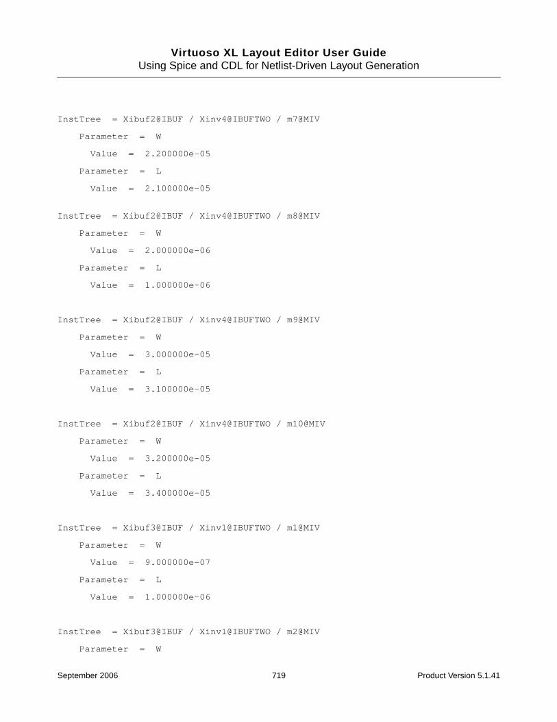
Virtuoso XL Layout Editor User GuideUsing Spice and CDL for Netlist-Driven Layout Generation
InstTree = Xibuf2@IBUF / Xinv4@IBUFTWO / m7@MIV
Parameter = W
Value = 2.200000e-05
Parameter = L
Value = 2.100000e-05
InstTree = Xibuf2@IBUF / Xinv4@IBUFTWO / m8@MIV
Parameter = W
Value = 2.000000e-06
Parameter = L
Value = 1.000000e-06
InstTree = Xibuf2@IBUF / Xinv4@IBUFTWO / m9@MIV
Parameter = W
Value = 3.000000e-05
Parameter = L
Value = 3.100000e-05
InstTree = Xibuf2@IBUF / Xinv4@IBUFTWO / m10@MIV
Parameter = W
Value = 3.200000e-05
Parameter = L
Value = 3.400000e-05
InstTree = Xibuf3@IBUF / Xinv1@IBUFTWO / m1@MIV
Parameter = W
Value = 9.000000e-07
Parameter = L
Value = 1.000000e-06
InstTree = Xibuf3@IBUF / Xinv1@IBUFTWO / m2@MIV
Parameter = W
September 2006 719 Product Version 5.1.41

Virtuoso XL Layout Editor User GuideUsing Spice and CDL for Netlist-Driven Layout Generation
Value = 3.000000e-06
Parameter = L
Value = 2.000000e-06
InstTree = Xibuf3@IBUF / Xinv1@IBUFTWO / m3@MIV
Parameter = W
Value = 1.000000e-04
Parameter = L
Value = 2.130000e-04
InstTree = Xibuf3@IBUF / Xinv1@IBUFTWO / m4@MIV
Parameter = W
Value = 1.010000e-04
Parameter = L
Value = 1.020000e-04
InstTree = Xibuf3@IBUF / Xinv1@IBUFTWO / m5@MIV
Parameter = W
Value = 3.000000e-05
Parameter = L
Value = 8.000000e-06
InstTree = Xibuf3@IBUF / Xinv1@IBUFTWO / m6@MIV
Parameter = W
Value = 3.000000e-05
Parameter = L
Value = 1.040000e-04
InstTree = Xibuf3@IBUF / Xinv1@IBUFTWO / m7@MIV
Parameter = W
Value = 2.200000e-05
Parameter = L
Value = 2.100000e-05
September 2006 720 Product Version 5.1.41

Virtuoso XL Layout Editor User GuideUsing Spice and CDL for Netlist-Driven Layout Generation
InstTree = Xibuf3@IBUF / Xinv1@IBUFTWO / m8@MIV
Parameter = W
Value = 2.000000e-06
Parameter = L
Value = 1.000000e-06
InstTree = Xibuf3@IBUF / Xinv1@IBUFTWO / m9@MIV
Parameter = W
Value = 3.000000e-05
Parameter = L
Value = 3.100000e-05
InstTree = Xibuf3@IBUF / Xinv1@IBUFTWO / m10@MIV
Parameter = W
Value = 3.200000e-05
Parameter = L
Value = 3.400000e-05
InstTree = Xibuf3@IBUF / Xinv2@IBUFTWO / m1@MIV
Parameter = W
Value = 9.000000e-07
Parameter = L
Value = 1.000000e-06
InstTree = Xibuf3@IBUF / Xinv2@IBUFTWO / m2@MIV
Parameter = W
Value = 3.000000e-06
Parameter = L
Value = 2.000000e-06
InstTree = Xibuf3@IBUF / Xinv2@IBUFTWO / m3@MIV
Parameter = W
September 2006 721 Product Version 5.1.41

Virtuoso XL Layout Editor User GuideUsing Spice and CDL for Netlist-Driven Layout Generation
Value = 2.010000e-04
Parameter = L
Value = 4.000000e-06
InstTree = Xibuf3@IBUF / Xinv2@IBUFTWO / m4@MIV
Parameter = W
Value = 6.000000e-06
Parameter = L
Value = 7.000000e-06
InstTree = Xibuf3@IBUF / Xinv2@IBUFTWO / m5@MIV
Parameter = W
Value = 3.000000e-05
Parameter = L
Value = 8.000000e-06
InstTree = Xibuf3@IBUF / Xinv2@IBUFTWO / m6@MIV
Parameter = W
Value = 3.000000e-05
Parameter = L
Value = 9.000000e-06
InstTree = Xibuf3@IBUF / Xinv2@IBUFTWO / m7@MIV
Parameter = W
Value = 2.200000e-05
Parameter = L
Value = 2.100000e-05
InstTree = Xibuf3@IBUF / Xinv2@IBUFTWO / m8@MIV
Parameter = W
Value = 2.000000e-06
Parameter = L
Value = 1.000000e-06
September 2006 722 Product Version 5.1.41

Virtuoso XL Layout Editor User GuideUsing Spice and CDL for Netlist-Driven Layout Generation
InstTree = Xibuf3@IBUF / Xinv2@IBUFTWO / m9@MIV
Parameter = W
Value = 3.000000e-05
Parameter = L
Value = 3.100000e-05
InstTree = Xibuf3@IBUF / Xinv2@IBUFTWO / m10@MIV
Parameter = W
Value = 3.200000e-05
Parameter = L
Value = 3.400000e-05
InstTree = Xibuf3@IBUF / Xinv3@IBUFTWO / m1@MIV
Parameter = W
Value = 9.000000e-07
Parameter = L
Value = 1.000000e-06
InstTree = Xibuf3@IBUF / Xinv3@IBUFTWO / m2@MIV
Parameter = W
Value = 3.000000e-06
Parameter = L
Value = 2.000000e-06
InstTree = Xibuf3@IBUF / Xinv3@IBUFTWO / m3@MIV
Parameter = W
Value = 5.000000e-06
Parameter = L
Value = 4.000000e-06
InstTree = Xibuf3@IBUF / Xinv3@IBUFTWO / m4@MIV
Parameter = W
September 2006 723 Product Version 5.1.41

Virtuoso XL Layout Editor User GuideUsing Spice and CDL for Netlist-Driven Layout Generation
Value = 6.000000e-06
Parameter = L
Value = 7.000000e-06
InstTree = Xibuf3@IBUF / Xinv3@IBUFTWO / m5@MIV
Parameter = W
Value = 3.000000e-05
Parameter = L
Value = 8.000000e-06
InstTree = Xibuf3@IBUF / Xinv3@IBUFTWO / m6@MIV
Parameter = W
Value = 3.000000e-05
Parameter = L
Value = 9.000000e-06
InstTree = Xibuf3@IBUF / Xinv3@IBUFTWO / m7@MIV
Parameter = W
Value = 2.200000e-05
Parameter = L
Value = 6.000000e-04
InstTree = Xibuf3@IBUF / Xinv3@IBUFTWO / m8@MIV
Parameter = W
Value = 2.000000e-06
Parameter = L
Value = 1.000000e-06
InstTree = Xibuf3@IBUF / Xinv3@IBUFTWO / m9@MIV
Parameter = W
Value = 3.000000e-05
Parameter = L
Value = 3.100000e-05
September 2006 724 Product Version 5.1.41

Virtuoso XL Layout Editor User GuideUsing Spice and CDL for Netlist-Driven Layout Generation
InstTree = Xibuf3@IBUF / Xinv3@IBUFTWO / m10@MIV
Parameter = W
Value = 3.200000e-05
Parameter = L
Value = 3.400000e-05
InstTree = Xibuf3@IBUF / Xinv4@IBUFTWO / m1@MIV
Parameter = W
Value = 9.000000e-07
Parameter = L
Value = 1.000000e-06
InstTree = Xibuf3@IBUF / Xinv4@IBUFTWO / m2@MIV
Parameter = W
Value = 3.000000e-06
Parameter = L
Value = 2.000000e-06
InstTree = Xibuf3@IBUF / Xinv4@IBUFTWO / m3@MIV
Parameter = W
Value = 5.000000e-06
Parameter = L
Value = 4.000000e-06
InstTree = Xibuf3@IBUF / Xinv4@IBUFTWO / m4@MIV
Parameter = W
Value = 2.000000e-04
Parameter = L
Value = 7.000000e-06
InstTree = Xibuf3@IBUF / Xinv4@IBUFTWO / m5@MIV
Parameter = W
September 2006 725 Product Version 5.1.41
Virtuoso XL Layout Editor User GuideUsing Spice and CDL for Netlist-Driven Layout Generation
Value = 3.000000e-05
Parameter = L
Value = 8.000000e-06
InstTree = Xibuf3@IBUF / Xinv4@IBUFTWO / m6@MIV
Parameter = W
Value = 3.000000e-05
Parameter = L
Value = 3.000000e-05
InstTree = Xibuf3@IBUF / Xinv4@IBUFTWO / m7@MIV
Parameter = W
Value = 2.200000e-05
Parameter = L
Value = 2.100000e-05
InstTree = Xibuf3@IBUF / Xinv4@IBUFTWO / m8@MIV
Parameter = W
Value = 2.000000e-06
Parameter = L
Value = 1.000000e-06
InstTree = Xibuf3@IBUF / Xinv4@IBUFTWO / m9@MIV
Parameter = W
Value = 3.000000e-05
Parameter = L
Value = 3.100000e-05
InstTree = Xibuf3@IBUF / Xinv4@IBUFTWO / m10@MIV
Parameter = W
Value = 3.200000e-05
Parameter = L
Value = 3.400000e-05
September 2006 726 Product Version 5.1.41

Virtuoso XL Layout Editor User GuideUsing Spice and CDL for Netlist-Driven Layout Generation
September 2006 727 Product Version 5.1.41

Virtuoso XL Layout Editor User Guide
D.do File Commands
When Virtuoso XL wire editing is enabled, you can use the commands below in a .do file andexecute the file through Virtuoso XL.
■ circuit
■ define/forget
■ do
■ limit
■ rule
■ set
For information about loading .do files, see “Using .do Files” on page 393.
Rule Hierarchy
Based on the available commands, use an object keyword with each command to determineat which level of rule precedence the routing rules are applied. The following table describesthe routing rule hierarchy from highest to lowest.
Rule Hierarchy
region class_class
region net
region class
region
via_image
class_class layer
class_class
September 2006 728 Product Version 5.1.41

Virtuoso XL Layout Editor User Guide.do File Commands
For example,
rule net (inter_layer_clear 3 (layer_pair poly diffusion))
would overwrite the following rule,
rule ic (inter_layer_clear 3 (layer_pair poly diffusion))
For more information about rules precedence, see “Understanding the Routing RuleHierarchy” in the Virtuoso Chip Assembly Router User Reference.
group layer
group
net layer
net
group_set layer
group_set
class layer
class
layer
ic
Rule Hierarchy
September 2006 729 Product Version 5.1.41

Virtuoso XL Layout Editor User Guide.do File Commands
Commands
circuit
Use the circuit command to assign length, delay, capacitance, resistance, shielding rules,routing priorities, vias, and routing layers to the following:
Syntax
For information, see circuit in the Virtuoso Chip Assembly Router User Reference.
Examplecircuit net J1 (length 4.4 3.9 (type ratio))
circuit net
circuit class
September 2006 730 Product Version 5.1.41

Virtuoso XL Layout Editor User Guide.do File Commands
define/forget
Use the define command to create or define the following types of objects or conditions:
Syntax
For information, see the following in the Virtuoso Chip Assembly Router User Reference.
Exampledefine (keepout myKeepout (rect signal 0 0 5 5))
define/forget group
define/forget group_set
define/forget keepout
define/forget region
group
group_set
keepout
September 2006 731 Product Version 5.1.41

Virtuoso XL Layout Editor User Guide.do File Commands
do
Use the do command to read and execute other .do files. Any additional .do files youinclude in a .do file, support the circuit, cost/tax, define/forget, limit, rule,and set commands only.
For more information, see “Using .do Files” on page 393.
September 2006 732 Product Version 5.1.41

Virtuoso XL Layout Editor User Guide.do File Commands
limit
Use the limit command to sets the number of number of vias allowed on a route.
Syntax
For more information, see limit in the Virtuoso Chip Assembly Router User Reference.
Examplelimit via 3
limit vias
September 2006 733 Product Version 5.1.41

Virtuoso XL Layout Editor User Guide.do File Commands
rule
Use the rule command to set design rules or routing constraints.
Syntax
For more information, see rule in the Virtuoso Chip Assembly Router User Reference.
Examplerule layer M1 (width 2.5) (clearance 1.5) (add_diag_clear 0.05)
rule net wr2 (shield_gap 1.0)
rule net wr2 (shield_width 3.0)
rule ic
rule class
rule class_class
rule group
rule group_set
rule layer
rule net
September 2006 734 Product Version 5.1.41
Virtuoso XL Layout Editor User Guide.do File Commands
set
The set command controls the following routing options.
Syntax
For more information, see set in the Virtuoso Chip Assembly Router User Reference.
set extend_wire_for_via
set trim_extensions
September 2006 735 Product Version 5.1.41

Virtuoso XL Layout Editor User Guide
EProperties
This appendix provides property names, descriptions, and graphical user interface (GUI)equivalents for the Virtuoso® XL Layout Editor (Virtuoso XL).
Important
Only the properties documented in this chapter are supported for public use. Allother Virtuoso XL properties, regardless of their name or prefix, and undocumentedaspects of the properties described below, are private and are subject to change atany time.
You can set some of the properties described in this chapter in the graphical user interface.This section tells you how to access the appropriate form.
Accessing the Symbol Master Add Property Form
Too add a user property to a symbol master,
1. From the Virtuoso Symbol Editing window, choose Edit – Properties – Cellview.
The Edit Cellview Properties form appears.
2. In the User Property section, click Add.
The Add Property form appears.
Accessing the Add CDF Parameter Form
To add a CDF parameter to a layout or schematic master,
1. From the CIW, choose Tools – CDF – Edit.
The Edit Component CDF form is displayed.
2. Specify the library and cell names and click Apply.
The form is populated with the options you can set.
September 2006 736 Product Version 5.1.41

Virtuoso XL Layout Editor User GuideProperties
3. In the Component Parameters section, click Add.
The Add CDF Parameter form is displayed.
Accessing the Layout Instance Add Property Form
To add a user property to an instance in the layout,
1. In the layout window design area, select the instance to which you want to add a property.
2. From the menu bar, choose Edit – Properties.
The Edit Instance Properties form is displayed.
3. Choose the Property radio button and click Add.
The Add Property form is displayed.
September 2006 737 Product Version 5.1.41
Virtuoso XL Layout Editor User GuideProperties
abutAccessDir
Defines the directions the pins are able to abut.
Property Name abutAccessDir
Value left, right, bottom, top
Value Type list
Additional Information
The abutAccessDir property ensures that the proper edges of devices are abutting; forexample, a left side to a right side, or a bottom to a top. Cells with rail pins need to addabutAccessDir properties for both sides because there is one pin for both right and leftsides of the cell left right. MOS cells have just one pin per side, so they need only onedirection left.
ExampledbReplaceProp(objId "abutAccessDir" "list" list("left"))
September 2006 738 Product Version 5.1.41

Virtuoso XL Layout Editor User GuideProperties
abutClass
Lets two different cells abut, even if their master cells are not the same.
Property Name abutClass
Value user defined name
Value Type string
Additional Information
The abutClass property is placed on the pin. Each pin targeted for abutment can belongto only one class, but pins on different edges of a cell can belong to different classes.Therefore, a cell can have multiple abutment classes but only one class per pin. The propertycan also be added to the cellview to implement a global class for all the pins. Automaticabutment checks for the abutClass property first on the pin and then on the master.
ExampledbReplaceProp(leftObj~>dbId "abutClass" "string" d_layer)
abutClass
interface cell
Class C
Class BClass A
September 2006 739 Product Version 5.1.41
Virtuoso XL Layout Editor User GuideProperties
abutCondInclusion
Defines the name of a boolean property that adds or removes contact shapes over thediffusion pin.
Property Name abutCondInclusion
Value name of pcell parameter
Value Type string
Additional Information
The abutCondInclusion parameter adds or removes the source or drain contact. You canconditionally include or exclude the contacts and connecting metal tab. You must conditionallyexclude these features if you are creating a graphical pcell. The pcell parameter must removeall features that are required for metal hookup and leave only the diffusion material to bestretched. For CMOS device abutment, you add this property to both the drain and the sourcesides of the device.
ExampledbReplaceProp(rightObj~>dbId "abutCondInclusion" "string" "rightCnt")
September 2006 740 Product Version 5.1.41

Virtuoso XL Layout Editor User GuideProperties
abutFunction
Specifies a user defined callback to process abutment and unabutment.
Property Name abutFunction
Value name of SKILL callback
Value Type string
Additional Information
The abutFunction is a callback that you create to process abutment and unabutment.The value of this property is a string consisting of the name of a user-defined Cadence®
SKILL function that is executed before abutment takes place. Automatic abutment passes thisfunction eight arguments in a list made up of the following information in this order:
1. The database identifier of the cell being abutted
2. The database identifier of the cell being abutted to
3. The database identifier of the pin figure of the cell being abutted
4. The database identifier of the pin figure of the cell being abutted to
5. The abutment access direction of pin being abutted (integer):
❑ 1 - top
❑ 2 - bottom
❑ 4 - left
❑ 8 - right
6. An integer with a valid value of 1or 2 that indicates connection condition:
❑ 1 - pins are connected to the same net and do not connect to any other pin
❑ 2 - pins are connected to the same net and the net connects to other pins
7. An integer specifying automatic abutment events:
❑ 1 - abutFunction computes and returns abutment offset (in the direction ofabutment)
❑ 2 - abutFunction adjusts pcell parameters for abutment. This is called before theoffset event.
September 2006 741 Product Version 5.1.41

Virtuoso XL Layout Editor User GuideProperties
❑ 3 - abutFunction adjusts pcell parameters for unabutment
❑ 4 - abutFunction computes and return spacing offset for non-abutment.
8. A database identifier that is the abutment group pointer available to events 2 and 3. It isused to store information so that unabutment can return pins to their original state. It isa generally-accepted method to use the group attribute of a cell to hold originalparameter values prior to modification by abutment.
abutFunction returns different values for different automatic abutment events:
■ Event 1 returns a floating-point number, which is the offset in user units needed to abutthe cells in the direction of abutment.
If it returns two floating-point numbers, the second number is the distance in user unitsthat the abutting cell is moved in the direction perpendicular to the abutting edge.
■ Event 2 return a value of true to allow abutment and nil to block abutment. When event2 returns nil, it must not change any parameters in any way, including setting them tonew values and then resetting them to the original values.
■ If the event is 3, it can return anything; the value returned is not used.
Example
Below is an example of the abutFunction property:
procedure( abutFunction(iA iB pA pB pASide connection event @optional(group nil)) prog((result)
case(event
(1 ; Compute offsetresult = getAbutmentOffset(iA iB pA pB pASide connection)
)
(2 ; Adjust pcell parametersresult = setAbutmentParams(iA iB pA pB pASide connection
group)
)
(3 ; Adjust pcell parameters back to defaultresetAbutmentParams(group iA iB)
result = t
)
(4 ; To get the spacing offset when pins are on different nets
if(instA~>w > 3.0 && instB~>w > 3.0
then
result = 3
else
result = 1
September 2006 742 Product Version 5.1.41
Virtuoso XL Layout Editor User GuideProperties
)
);; end of case 4
(t ; Anything else return a nilresult = nil
)
)
return(result)
)
)
Note: If you are using pcells, you can use the default abutment functions.
If each pin being abutted has a different abutFunction defined, automatic abutment callsonly the function defined by the pin in the cell being moved.
ExampledbReplaceProp(obj "abutFunction" "string" "mosAbutFunc")
September 2006 743 Product Version 5.1.41

Virtuoso XL Layout Editor User GuideProperties
abutGateNet
Defines the name of the net the gate shapes are on.
Property Name abutGateNet
Value name of pcell parameter
Value Type string
Additional Information
This parameter identifies the gate pins so the abutment software knows where the edge ofthe gate is. In the example, the value G is the name of the gate net inside the pcell.
ExampledbReplaceProp(leftObj~>dbId "abutGateNet" "string" "G")
September 2006 744 Product Version 5.1.41
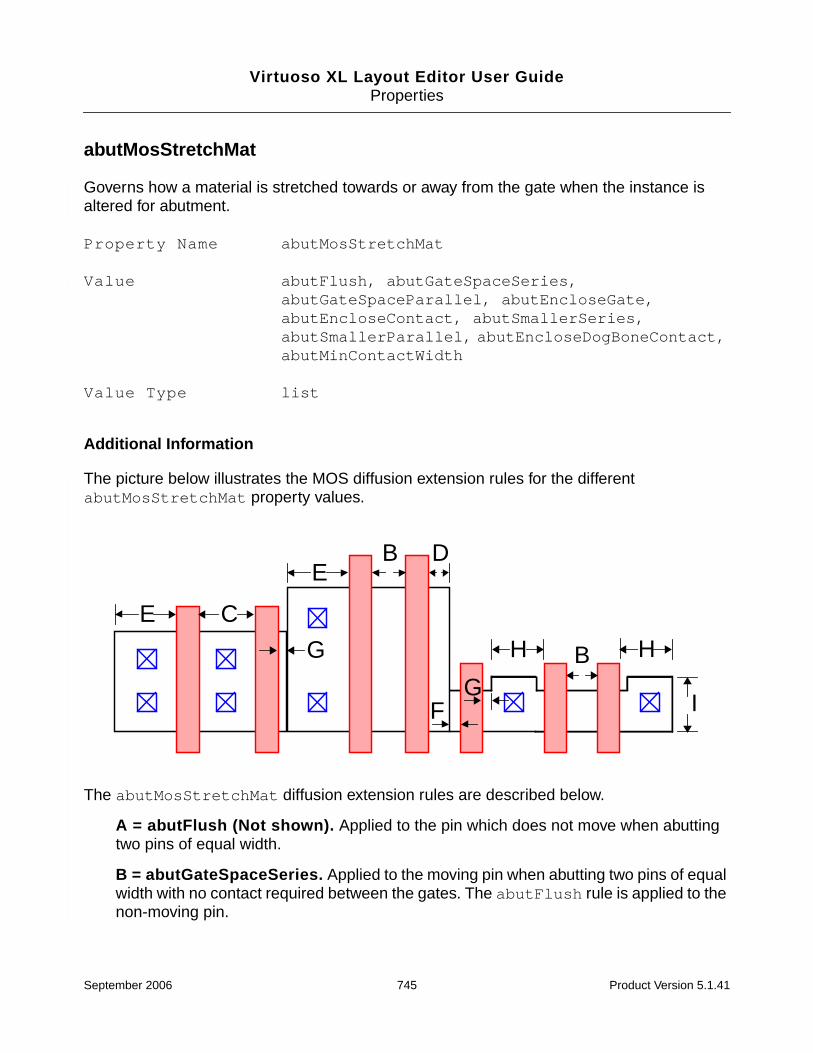
Virtuoso XL Layout Editor User GuideProperties
abutMosStretchMat
Governs how a material is stretched towards or away from the gate when the instance isaltered for abutment.
Property Name abutMosStretchMat
Value abutFlush, abutGateSpaceSeries,abutGateSpaceParallel, abutEncloseGate,abutEncloseContact, abutSmallerSeries,abutSmallerParallel, abutEncloseDogBoneContact,abutMinContactWidth
Value Type list
Additional Information
The picture below illustrates the MOS diffusion extension rules for the differentabutMosStretchMat property values.
The abutMosStretchMat diffusion extension rules are described below.
A = abutFlush (Not shown). Applied to the pin which does not move when abuttingtwo pins of equal width.
B = abutGateSpaceSeries. Applied to the moving pin when abutting two pins of equalwidth with no contact required between the gates. The abutFlush rule is applied to thenon-moving pin.
E C
B D
F
H
G
G B
E
H
I
September 2006 745 Product Version 5.1.41

Virtuoso XL Layout Editor User GuideProperties
C = abutGateSpaceParallel. Applied to the moving pin when abutting pins of equalwidth where a contact is required between the gates and the pin widths are greater thanor equal to the abutMinContactWidth rule. The abutFlush rule is applied to thenon-moving pin.
D = abutEncloseGate. Applied to the larger of two abutting pins when a contact is notrequired between the gates. The abutSmallerSeries rule is applied to the smaller ofthe two pins being abutted.
E = abutEncloseContact. Applied to the larger of two different-width abutting pinswhen a contact is required between the gates but only if the width of the larger pin isgreater than or equal to the abutMinContactWidth rule. TheabutSmallerParallel rule is applied to the smaller of the two pins being abutted.
F = abutSmallerSeries. Applied to the smaller of two abutting pins when a contact isnot required between the gates.
G = abutSmallerParallel. Applied to the smaller of two abutting pins when a contact isrequired between the gates.
H = abutEncloseDogBoneContact. Applied when contacts are required and thewidth of the device is less than the abutMinContactWidth rule. It is applied to thelarger of two different-width pins or to the moving pin when the two pins are of equalwidth.
I = abutMinContactWidth. Determines whether to use the abutEncloseContactrule or the abutEncloseDogBoneContact rule when a contact is required betweengates.
Exampleslist(t_stretchParamNamelist(“abutFlush” f_value)list(“abutGateSpaceSeries” f_value)list(“abutGateSpaceParallel” f_value)list(“abutEncloseGate” f_value)list(“abutEncloseContact” f_value)list(“abutSmallerSeries” f_value)list(“abutSmallerParallel” f_value)list(“abutEncloseDogBoneContact” f_value)list(“abutMinContactWidth” f_value)
)
The example below illustrates the properties being applied to pins on the left and right edgesof a MOS pcell.
■ The pin rectangles were created by the rodCreateRect command and arereferenced by two variables called leftObj and rightObj pointing to their rod objectIDs.
September 2006 746 Product Version 5.1.41

Virtuoso XL Layout Editor User GuideProperties
■ The pcell parameters that control the stretching of the left and right pin extensions pastthe gate are called leftSt and rightSt.
■ All abutment extension rule values in the abutMosStretchMat property list must benumeric.
■ The pcell parameters that control whether or not the left or right pins have contacts overthem are leftCnt and rightCnt.
■ The contact parameters must be of type Boolean.
;; Definition of variables used in the abutRuleList calculations for;; the abutMosStretchMat property.
;; cw = contact width;; doc = diffusion overlap of contact;; pps = poly to poly space;; pcs = poly to contact space;; pds = poly to diffusion space
abutRuleList = list(list("abutFlush" 0.0)list("abutGateSpaceSeries" pps)list("abutGateSpaceParallel" max((cw + (pcs * 2)) pps))list("abutEncloseGate" doc)list("abutEncloseContact" doc + cw + pcs)list("abutSmallerSeries" max((pps - doc) pds))list("abutSmallerParallel" max((pcs - doc) (pps - pcs - cw - doc) pds))list("abutEncloseDogBoneContact" cw + doc + max(pds+doc pcs))list("abutMinContactWidth" cw + (2 * doc))
)
;; Definition of variables used for abutClass and autoSpacer property values.;; d_layer = diffusion layer (used for abutClass property value);; dds = diffusion to diffusion space (used by autoSpacer)
;; Add the abutment and spacer properties to the left diffusion pin.
leftObj~>dbId~>pin~>name = “leftContact”dbReplaceProp(leftObj~>dbId "abutCondInclusion" "string" "leftCnt")dbReplaceProp(leftObj~>dbId "abutMosStretchMat" "list"cons("leftSt" abutRuleList))dbReplaceProp(leftObj~>dbId "abutClass" "string" d_layer)dbReplaceProp(leftObj~>dbId "abutGateNet" "string" "G")dbReplaceProp(leftObj~>dbId "abutAccessDir" "list" list("left"))dbReplaceProp(leftObj~>dbId "vxlInstSpacingDir" "list" list("left"))dbReplaceProp(leftObj~>dbId "vxlInstSpacingRule" "float" dds)
;; Add the abutment and spacer properties to the right diffusion pin.
rightObj~>dbId~>pin~>name = “rightContact”dbReplaceProp(rightObj~>dbId "abutCondInclusion" "string" "rightCnt")dbReplaceProp(rightObj~>dbId "abutMosStretchMat" "list"cons("rightSt" abutRuleList))dbReplaceProp(rightObj~>dbId "abutClass" "string" d_layer)dbReplaceProp(rightObj~>dbId "abutGateNet" "string" "G")dbReplaceProp(rightObj~>dbId "abutAccessDir" "list" list("right"))dbReplaceProp(rightObj~>dbId "vxlInstSpacingDir" "list" list("right"))dbReplaceProp(rightObj~>dbId "vxlInstSpacingRule" "float" dds)
September 2006 747 Product Version 5.1.41

Virtuoso XL Layout Editor User GuideProperties
abutStretchMat
Stretches the material toward or away from the gate when the instance is altered forabutment.
Property Name abutStretchMat
Value drainStretch, abutMinExt, abutRul1Ext,abutRule2Ext, abutContactExt
Value Type list
Additional Information
The default value of the stretch parameter is the distance from the edge of the material to theedge of the gate. Numeric values are in user units.
■ The first element in the list (drainStretch) is the name of the stretchable materialparameter. You name this parameter yourself to identify the material to be stretched.
■ The second element in the list (abutMinExt) is the rule for minimum diffusionoverhang from the edge of the poly gate. The argument to this element (0.5) is the rulevalue.
■ The third element in the list (abutRule1Ext) is the polysilicon-layer-to-polysilicon-layer rule. This rule is used when the net connecting the two instances does not sharethe net with any other pin.
■ The fourth element in the list (abutRule2Ext) is the polysilicon-layer-to-diffusion-layerrule. The rule is used when the transistor width is different for the two instances beingabutted.
Caution
The placer does not take the abutRule2Ext into consideration, resultingin illegal overlap markers.
■ The fifth element in the list (abutContactExt) is the diffusion extension value usedwhen one of the contacts needs to be added during the abutment process. With thecontacts off by default, the abutment program needs to know how close to move theselected cell to abut properly.
September 2006 748 Product Version 5.1.41

Virtuoso XL Layout Editor User GuideProperties
ExampleabutStretchMat list (“drainStretch” ilList
list ("abutMinExt" 0.5)list ("abutRule1Ext" 0.75)list ("abutRule2Ext" 1.0)list ("abutContactExt" 3.0))
September 2006 749 Product Version 5.1.41

Virtuoso XL Layout Editor User GuideProperties
abutOffset
Specifies a distance in user units to offset the reference edge to the outside direction of thecell. A negative number causes the pins to overlap.
Note: The reference edge is the outside edge of the pin that triggered the abutment on eachcell in the direction defined by the abutment direction.
Property Name abutOffset
Value floating point number
Value Type float
Additional Information
If the abutFunction compute offset event (event 1) returns nil, automatic abutmentlooks for an abutOffset property on the pin and applies the value of this property as the offset.If there is no abutOffset property, automatic abutment uses the outside edge of the pinwith no offset.
September 2006 750 Product Version 5.1.41

Virtuoso XL Layout Editor User GuideProperties
If the pin of the device being abutted overlaps the other pin on the bottom or top, the pins arealigned by the bottom or top edges respectively. This also applies from side to side whenabutment is vertical.
ExampleabutOffset 5
res
res
res
res
Interactive move places one cellapproximately overlapping another
abutOffset = -5
res
res
res
res
abutOffset = 5
Cells are first aligned and then theoffset is applied. In this case,abutOffset = 0 or is not set
September 2006 751 Product Version 5.1.41
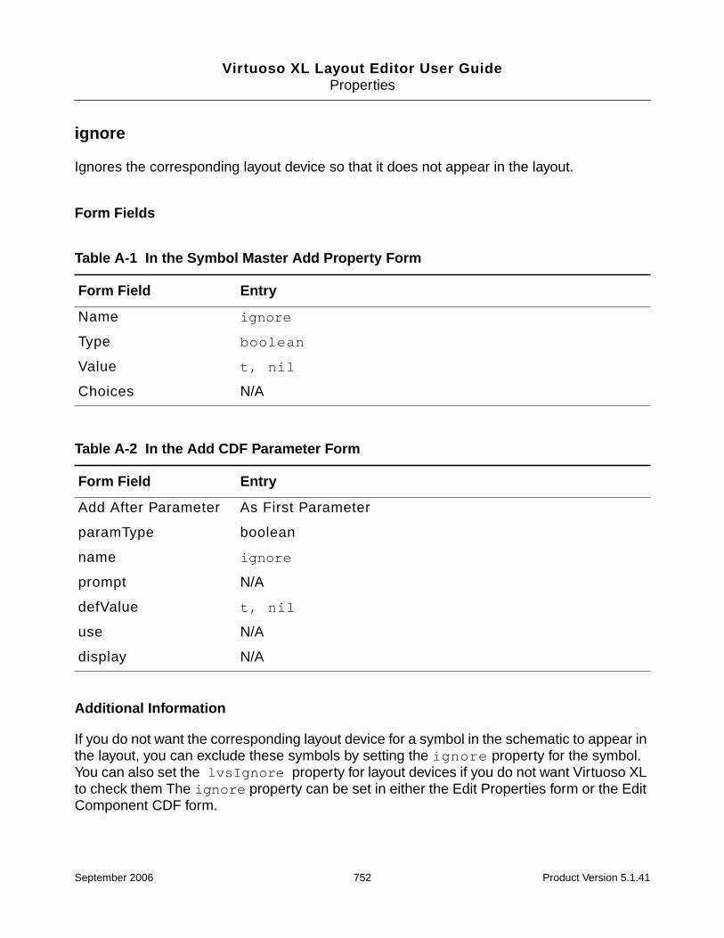
Virtuoso XL Layout Editor User GuideProperties
ignore
Ignores the corresponding layout device so that it does not appear in the layout.
Form Fields
Additional Information
If you do not want the corresponding layout device for a symbol in the schematic to appear inthe layout, you can exclude these symbols by setting the ignore property for the symbol.You can also set the lvsIgnore property for layout devices if you do not want Virtuoso XLto check them The ignore property can be set in either the Edit Properties form or the EditComponent CDF form.
Table A-1 In the Symbol Master Add Property Form
Form Field Entry
Name ignore
Type boolean
Value t, nil
Choices N/A
Table A-2 In the Add CDF Parameter Form
Form Field Entry
Add After Parameter As First Parameter
paramType boolean
name ignore
prompt N/A
defValue t, nil
use N/A
display N/A
September 2006 752 Product Version 5.1.41

Virtuoso XL Layout Editor User GuideProperties
lxAutoAbut
Important
lxAutoAbut is only a CDF property.
If either instance of an abutment pair has the lxAutoAbut property set to nil, the pair areprevented from abutting.
Form Fields
Table A-3 In the Add CDF Parameter Form
Form Field Entry
Add After Parameter As First Parameter
paramType boolean
name ignore
prompt N/A
defValue t, nil
use N/A
display N/A
September 2006 753 Product Version 5.1.41
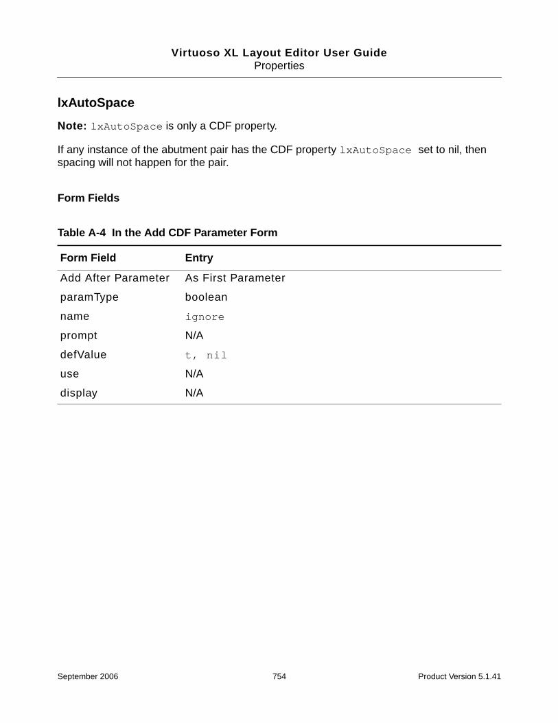
Virtuoso XL Layout Editor User GuideProperties
lxAutoSpace
Note: lxAutoSpace is only a CDF property.
If any instance of the abutment pair has the CDF property lxAutoSpace set to nil, thenspacing will not happen for the pair.
Form Fields
Table A-4 In the Add CDF Parameter Form
Form Field Entry
Add After Parameter As First Parameter
paramType boolean
name ignore
prompt N/A
defValue t, nil
use N/A
display N/A
September 2006 754 Product Version 5.1.41

Virtuoso XL Layout Editor User GuideProperties
lxBlockExtractCheck
lxBlockExtractCheck boolean { t | nil }
Prevents the extractor from checking the connectivity between a shape or instance and othershapes or instances it touches.
You can attach the lxBlockExtractCheck property on a shape or instance master. Usethis property to prevent extraction of instances of masters that are not compatible with LayoutXL or which would adversely affect the performance of the extractor.
Example
In the illustration above, the layer that crosses net1 and net2 has the propertylxBlockExtractCheck, so there is no connectivity checking between this shape and allothers it touches. If the shape does not already have connectivity, the software assigns a netname to it.
If you assign connectivity to the shape manually or using Cadence® SKILL code, it will keepthe connectivity, but the shape will always be considered incomplete because the softwarewill not check it when checking the connectivity.
For hierarchical connectivity to work for pcells, the connectivity must be defined on theshapes within the pcell. You can assign connectivity interactively using the Connectivity –Assign Nets command or using SKILL functions.
Layout instance Add Property form
Name lxAutoSpace
Type Boolean
Value t | nil
net1 net2
metal1
This shape crosses net1 and net2
September 2006 755 Product Version 5.1.41

Virtuoso XL Layout Editor User GuideProperties
lxBlockOverlapCheck
Specifies that the extractor not check whether a nonoverlap layer of this shape or instance istouching a nonoverlap layer at the current cellview level. Defined on a shape, instance, orinstance master.
Form Fields
Additional Information
In the illustration below, the lxBlockOverlapCheck property can be defined on thediffusion layer so that no short marker is created.
For example, if you define the lxBlockOverlapCheck property on a shape in cellview “A”,you will not see any markers when overlapping the shape with an instance. However, ifcellview “A” is placed inside cellview “B”, and a noOverlap layer is drawn over the shape incellview “A”, then a marker will appear. This happens even though the shape in cellview “A”has the lxBlockOverlapCheck property defined.
Table A-5 In the layout Add Property Form
Form Field Entry
Name lxBlockExtractCheck
Type boolean
Value t, nil
Choices N/A
G
G
DSdiffusion
poly
A: extra layer by mistake
September 2006 756 Product Version 5.1.41
Virtuoso XL Layout Editor User GuideProperties
lxCombination
lxCombination string t_expression
Builds a complex set of devices comprising series (sfactor) and parallel (mfactor)connections.
Use lxCombination to define a set of resistors to help achieve maximum density by puttingthe resistors into spaces otherwise not utilized. This facilitates the creation of a closeapproximation of the resistance value as defined in the schematic, without violating themanufacturing grid.
Define lxCombination as a CDF parameter or an instance property, using a valid stringvalue.
Notes
■ You can also use lxCombination to define the topology for a network of capacitors.However, in this case, the property describes only the topology of the network; thevalues entered do not equate to the total capacitance of the network.
■ To ensure that lxCombination expressions are evaluated correctly, you must set thelxEvalCDFCallbacks environment variable to t before generating your resistors.
■ If the lxCombination property is defined on the schematic symbol, the r parameter isignored by the Connectivity – Generate – All From Source and Connectivity –
Symbol master Add Property form
Name lxCombination
Type string
Value t_expression
Add CDF Parameter form
Add After Parameter As First Parameter
paramType string
name lxCombination
defValue t_expression
September 2006 757 Product Version 5.1.41
Virtuoso XL Layout Editor User GuideProperties
Update – Components And Nets commands. The layout instances will have thecorrect parameters based on the lxCombination factor setting.
Naming Convention
Devices defined using the lxCombination property in the schematic are namedinstName.msinteger in the layout. For example, if you have a schematic instancenamed R0 with
lxCombination = 2*10K + 1*100K
the layout instances generated are named as follows.
Example
The following lxCombination expression divides a single resistor in the schematic into acomplex set of devices in the layout
(2k*2)/3+1500/4
where
2k, 2, 3, 1500, and 4 are device parameter values
* and + are series connections
/ is a parallel connection
Note: The difference between the series connection symbols is that + can be followed by anexpression, whereas * can be followed only by an integer. The / parallel connection can alsobe followed only by an integer.
Schematic Layout
R0 |R0.ms1|R0.ms2|R0.ms3
September 2006 758 Product Version 5.1.41
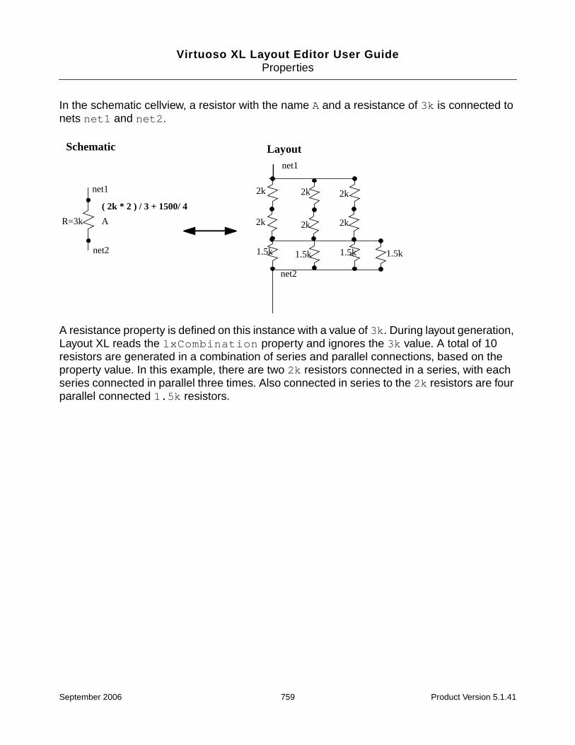
Virtuoso XL Layout Editor User GuideProperties
In the schematic cellview, a resistor with the name A and a resistance of 3k is connected tonets net1 and net2.
A resistance property is defined on this instance with a value of 3k. During layout generation,Layout XL reads the lxCombination property and ignores the 3k value. A total of 10resistors are generated in a combination of series and parallel connections, based on theproperty value. In this example, there are two 2k resistors connected in a series, with eachseries connected in parallel three times. Also connected in series to the 2k resistors are fourparallel connected 1.5k resistors.
A
net1
net2
Schematic
net1
net2
Layout
( 2k * 2 ) / 3 + 1500/ 4
R=3k
2k
2k
2k
2k
2k
2k
1.5k 1.5k1.5k 1.5k
September 2006 759 Product Version 5.1.41

Virtuoso XL Layout Editor User GuideProperties
lxIgnoredParams
Specify device parameters to be excluded when using the Connectivity – Check – AgainstSource command or transferred to the layout when using the Connectivity – Update –Layout Parameters command
Tip
Cadence recommends that you use lxParamsToIgnore instead oflxIgnoredParams. However, you can continue to use lxIgnoredParams bysetting set the checkOldIgnoredParamsProps environment variable to t.
Form Fields
Table A-6 In the Symbol Master Add Property Form
Form Field Entry
Name lxIgnoredParams
Type string
Value parameter name
Choices N/A
Table A-7 In the Add CDF Parameter Form
Form Field Entry
Add After Parameter As First Parameter
paramType string
name lxIgnoredParams
prompt N/A
defValue parameter name
use N/A
display N/A
September 2006 760 Product Version 5.1.41

Virtuoso XL Layout Editor User GuideProperties
lxIgnoreParamsForCAS
Specifies device parameters and properties to be ignored by the Connectivity – Check –Against Source command.
Tip
Cadence recommends that you use lxParamsToIgnoreForCheck instead oflxIgnoreParamsForCAS. However, you can continue to uselxIgnoreParamsForCAS by setting set the checkOldIgnoredParamsPropsenvironment variable to t.
Form Fields
Table A-8 In the Symbol Master Add Property Form
Form Field Entry
Name lxIgnoreParamsForCAS
Type string
Value parameter/property name
Choices N/A
Table A-9 In the Add CDF Parameter Form
Form Field Entry
Add After Parameter As First Parameter
paramType string
name lxIgnoreParamsForCAS
prompt N/A
defValue parameter/property name
use N/A
display N/A
September 2006 761 Product Version 5.1.41
Virtuoso XL Layout Editor User GuideProperties
lxMfactorSplit
Controls whether Virtuoso XL places a schematic device with the mfactor property as multipledevices in the layout.
Use this property to override the global value set using the mfactorSplit environment variable.
Form Fields
Table A-10 In the Symbol Master Add Property Form
Form Field Entry
Name lxMfactorSplit
Type boolean
Value t, nil
Choices N/A
Table A-11 In the Add CDF Parameter Form
Form Field Entry
Add After Parameter As First Parameter
paramType boolean
name lxMfactorSplit
prompt N/A
defValue t, nil
use N/A
display N/A
September 2006 762 Product Version 5.1.41

Virtuoso XL Layout Editor User GuideProperties
lxNetNamePrefix
Specify the lxNetNamePrefix property to add unique prefixes to the internal nets.
Form Fields
Additional Information
The names of the internal nets are generated in the layout using Virtuoso XL conventions.Youcan use the lxNetNamePrefix property to add unique prefixes to the internal nets (validvalues: string).
Note: lxNetNamePrefix can only be used with devices which have the lxCombinationproperty or sfactor parameter.
Table A-12 In the Symbol Master Add Property Form
Form Field Entry
Name lxNetNamePrefix
Type string
Value unique prefix
Choices N/A
Table A-13 In the Add CDF Parameter Form
Form Field Entry
Add After Parameter As First Parameter
paramType string
name lxNetNamePrefix
prompt N/A
defValue unique prefix
use N/A
display N/A
September 2006 763 Product Version 5.1.41

Virtuoso XL Layout Editor User GuideProperties
For example, generating layout devices from the R device in the schematic adds|R|net.ms1, |R|net.ms2, and |R|net.ms3 names to the internal nets.
Using the lxNetNamePrefix property, you can choose to add the prefix X to the internal netnames. The names change to |R|XnetMS1, |R|XnetMS2, and |R|XnetMS3.
A
net1
net2
Schematic
net1
net2
Layout
R=3k
2k
2k
2k
2k
1.5k 1.5k1.5k 1.5k
|R|net.ms1 |R|net.ms2 |R|net.ms3
2k
2k
net1
net2
Layout
2k
2k
2k
2k
1.5k 1.5k1.5k 1.5k
|R|Xnet.ms1 |R|Xnet.ms2 |R|Xnet.ms3
2k
2k
September 2006 764 Product Version 5.1.41

Virtuoso XL Layout Editor User GuideProperties
lxParamsToIgnore
Specifies device parameters to be ignored when using the following Virtuoso XL update andcheck commands.
■ Design – Gen From Source
■ Create – Pick From Schematic
■ Create – Clone
■ Connectivity – Check – Against Source
■ Connectivity – Update – Components and Nets
■ Connectivity – Update – Layout Parameters
■ Connectivity – Update – Schematic Parameters
Important
Cadence recommends that you use lxParamsToIgnore instead of thelxIgnoredParams property.
Form Fields
Table A-14 In the Symbol Master Add Property Form
Form Field Entry
Name lxParamsToIgnore
Type string
Value parameter/property name
Choices N/A
Table A-15 In the Add CDF Parameter Form
Form Field Entry
Add After Parameter As First Parameter
paramType string
September 2006 765 Product Version 5.1.41

Virtuoso XL Layout Editor User GuideProperties
name lxParamsToIgnore
prompt N/A
defValue parameter/property name
use N/A
display N/A
Table A-15 In the Add CDF Parameter Form
Form Field Entry
September 2006 766 Product Version 5.1.41

Virtuoso XL Layout Editor User GuideProperties
lxParamsToIgnoreForCheck
Specifies device parameters and properties to be ignored by the Connectivity – Check –Against Source command.
Important
Cadence recommends that you use lxParamsToIgnoreForCheck instead of thelxIgnoreParamsForCAS property.
Form Fields
Table A-16 In the Symbol Master Add Property Form
Form Field Entry
Name lxParamsToIgnoreForCheck
Type string
Value parameter/property name
Choices N/A
Table A-17 In the Add CDF Parameter Form
Form Field Entry
Add After Parameter As First Parameter
paramType string
name lxParamsToIgnoreForCheck
prompt N/A
defValue parameter/property name
use N/A
display N/A
September 2006 767 Product Version 5.1.41

Virtuoso XL Layout Editor User GuideProperties
lxRemoveDevice
Causes parasitic devices to be ignored.
Use lxRemoveDevice to merge nets connected to the terminals of a single instance at atime. Its use is not restricted to only two terminals; it also works for more than two terminals.
You can also use the property to merge nets connected to the terminals of an iteratedinstance. To do so, add the property to the instance being iterated, not to the hierarchicalblock containing the iterated instances.
Form Fields
Table A-18 In the Symbol Master Add Property Form
Form Field Entry
Name lxRemoveDevice
Type string
Value “(short(list_of_terminals)...[function({arguments})])”
Choices N/A
Table A-19 In the Add CDF Parameter Form
Form Field Entry
Add After Parameter As First Parameter
paramType string
name lxRemoveDevice
prompt N/A
defValue “(short(list_of_terminals)...[function({arguments})])”
use N/A
display N/A
September 2006 768 Product Version 5.1.41

Virtuoso XL Layout Editor User GuideProperties
Additional Information
Caution
If the Diva LVS removeDevice rule and the lxRemoveDevice property areset on the same instance or master, running Diva LVS causes an error.
Rules for lxRemoveDevice Merging
The rules below are used to decide which net survives after the device is shorted.
1. Global nets or nets connected to I/O pins always survive.
2. If there are no global or external nets, the net at a higher level of hierarchy survives; forexample, net1 survives over /I1/net2.
3. If the nets are at the same level of hierarchy, the net with the shortest name survives; forexample, netA survives over netBCD.
4. If the nets are at the same level of hierarchy and their names are of the same length,alphabetical order is used; for example, netM survives over netN.
Rules for lxRemoveDevice Handling
1. A single function applies for all the short() lists.
2. If the function is missing, the terminals are shorted as specified in the short rule.
3. If the device is not removed, the terminals are not shorted.
4. A warning is issued when the device is not ignored in the netlisting.
Example
For a resistor with terminal names PLUS and MINUS, a simple lxRemoveDevice propertywould be as follows.
■ (short(PLUS MINUS))
This property shorts the terminals.
■ (short(PLUS MINUS) funcR(r))
Here, the resistor is shorted only if the user-defined SKILL function funcR returns non-nil.
September 2006 769 Product Version 5.1.41

Virtuoso XL Layout Editor User GuideProperties
Important
The arguments to the function must be instance or cell parameter names. VirtuosoXL replaces the names with the evaluated values of the properties when calling thefunction.
Note: The initial and final parentheses must be included.
The function must already be defined. The recommended place to define this function isin the .cdsinit or libInit.il file. A sample funcR for the above case would be
procedure( funcR(r)if(r<100 then telse nil)
)
September 2006 770 Product Version 5.1.41

Virtuoso XL Layout Editor User GuideProperties
lxRounding
Defines how the value of a specified parameter on a cell master or schematic instance isrounded when it is evaluated by Virtuoso XL.
You can use lxRounding with the lxDeviceWidth parameter to prevent folded devicesfrom becoming off-grid.
You can also use it to set a tolerance when Virtuoso XL compares parameter values duringthe following commands.
■ Design – Gen From Source
■ Connectivity – Check – Against Source
■ Connectivity – Update – Layout Parameters
■ Connectivity – Update – Schematic Parameters
The definition comprises three parts; (paramName float keyword).
■ paramName is the name of the parameter to be rounded. Valid names are
❑ Those specified by the mfactorSplitParamNames environment variable
❑ Those specified by the sfactorParam environment variable
❑ The width parameter name specified in the component type to which the cellview isassigned.
■ float is a number. If the specified parameter is to be rounded, the value returned is anonzero integer multiple of the float value.
Note: Virtuoso XL never rounds to zero. If the closest rounded value is zero, no roundingtakes place.
■ keyword specifies the rounding method used. Allowed values are
❑ floor rounds to the nonzero integer multiple at or below the current value
❑ ceil rounds to the nonzero integer multiple at or above the current value
❑ round rounds to the nonzero integer multiple at or closest to the current value
For example, lxRounding = (w 0.05 round) rounds the value of w to the closestmultiple of 0.05 nanometers.
September 2006 771 Product Version 5.1.41
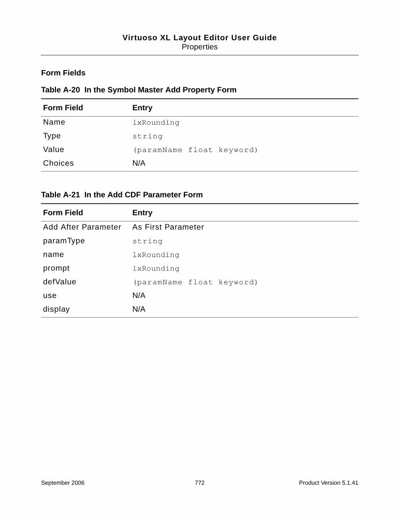
Virtuoso XL Layout Editor User GuideProperties
Form Fields
Table A-20 In the Symbol Master Add Property Form
Form Field Entry
Name lxRounding
Type string
Value (paramName float keyword)
Choices N/A
Table A-21 In the Add CDF Parameter Form
Form Field Entry
Add After Parameter As First Parameter
paramType string
name lxRounding
prompt lxRounding
defValue (paramName float keyword)
use N/A
display N/A
September 2006 772 Product Version 5.1.41

Virtuoso XL Layout Editor User GuideProperties
lxSeriesTerms
Understands the connectivity of the devices with sfactor greater than 1 and instanceterminals greater than 2.
Form Fields
Additional Information
The lxSeriesTerms property must be defined on the instance in the schematic in order forVirtuoso XL to understand the connectivity of the devices with sfactor >1 and instanceterminals>2. The description below shows setting the lxSeriesTerms PLUS and MINUS ontwo instance terminals.
lxSeriesTerms = “PLUS MINUS”
The Generate Multiple Instances option must be turned on in the Layout XL Options form.
Table A-22 In the Symbol Master Add Property Form
Form Field Entry
Name lxSeriesTerms
Type string
Value “PLUS MINUS”
Choices N/A
Table A-23 In the Add CDF Parameter Form
Form Field Entry
Add After Parameter As First Parameter
paramType string
name lxSeriesTerms
prompt N/A
defValue “PLUS MINUS”
use N/A
display N/A
September 2006 773 Product Version 5.1.41

Virtuoso XL Layout Editor User GuideProperties
lxStickyNet
Allows a shape to retain the assigned connectivity when it is modified in some way.
Virtuoso XL adds the lxStickyNet property automatically to a shape when a net isassigned to that shape using one of the commands listed below.
■ Create – Rectangle
■ Create – Polygon
■ Create – Path
■ Create – Multipart Path
■ Create – Conics – Circle
■ Create – Conics – Ellipse
■ Create – Conics – Donut
■ Connectivity – Add Shape to Net
The property remains in effect until you turn it off or remove it using the Edit – Propertiescommand. You can also manually add the property using the Edit – Properties command.
Form Fields
Additional Information
In the Virtuoso environment there are two types of nets, known and unknown.
■ known nets are nets that are defined by pins and components (for example clkA).
If a shape that is not assigned to a net touches a shape on known net, the shape isassigned to that net. When the net assignment is defined by pins and components
Table A-24 In the layout Add Property Form
Form Field Entry
Name lxStickyNet
Type boolean
Value t, nil
Choices N/A
September 2006 774 Product Version 5.1.41
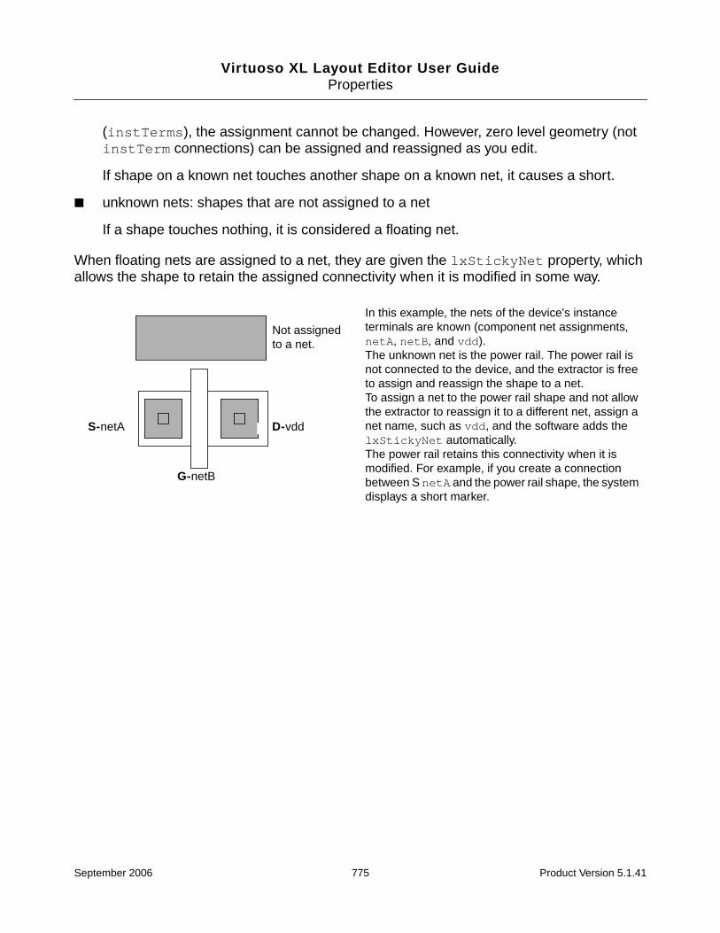
Virtuoso XL Layout Editor User GuideProperties
(instTerms), the assignment cannot be changed. However, zero level geometry (notinstTerm connections) can be assigned and reassigned as you edit.
If shape on a known net touches another shape on a known net, it causes a short.
■ unknown nets: shapes that are not assigned to a net
If a shape touches nothing, it is considered a floating net.
When floating nets are assigned to a net, they are given the lxStickyNet property, whichallows the shape to retain the assigned connectivity when it is modified in some way.
S-netA D-vdd
G-netB
In this example, the nets of the device's instanceterminals are known (component net assignments,netA, netB, and vdd).The unknown net is the power rail. The power rail isnot connected to the device, and the extractor is freeto assign and reassign the shape to a net.To assign a net to the power rail shape and not allowthe extractor to reassign it to a different net, assign anet name, such as vdd, and the software adds thelxStickyNet automatically.The power rail retains this connectivity when it ismodified. For example, if you create a connectionbetween S netA and the power rail shape, the systemdisplays a short marker.
Not assignedto a net.
September 2006 775 Product Version 5.1.41

Virtuoso XL Layout Editor User GuideProperties
lxStopList
Lists the names of views at which Virtuoso XL stops traversing the design. The stop view isgenerally the view with the most detailed description or the one with no further layers ofhierarchy.
Form Fields
Additional Information
For more information on hierarchy expansion using the lxStopList and lxViewListproperties, see “How the Netlister Expands Hierarchy” in Chapter 3 of the Virtuoso AnalogDesign Environment User Guide.
Table A-25 In the Symbol Master Add Property Form
Form Field Entry
Name lxStopList
Type string
Value layout compacted symbolic
Choices N/A
Table A-26 In the Add CDF Parameter Form
Form Field Entry
Add After Parameter As First Parameter
paramType string
name lxStopList
prompt N/A
defValue layout compacted symbolic
use N/A
display N/A
September 2006 776 Product Version 5.1.41

Virtuoso XL Layout Editor User GuideProperties
Note: In releases 4.3.4 and earlier, the maskLayoutViewName property specified whichview to use in the layout. Virtuoso XL still recognizes this property if you have not defined thelxStopList property.
After generating a layout, you can change the view using the layout window Connectivity –Change Instance View command. The Change Instance View form lets you choose a viewfrom the list defined in the lxStopList property.
September 2006 777 Product Version 5.1.41
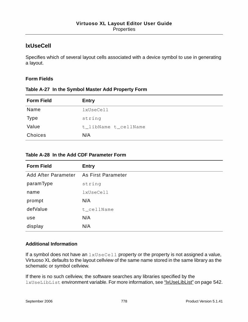
Virtuoso XL Layout Editor User GuideProperties
lxUseCell
Specifies which of several layout cells associated with a device symbol to use in generatinga layout.
Form Fields
Additional Information
If a symbol does not have an lxUseCell property or the property is not assigned a value,Virtuoso XL defaults to the layout cellview of the same name stored in the same library as theschematic or symbol cellview.
If there is no such cellview, the software searches any libraries specified by thelxUseLibList environment variable. For more information, see “lxUseLibList” on page 542.
Table A-27 In the Symbol Master Add Property Form
Form Field Entry
Name lxUseCell
Type string
Value t_libName t_cellName
Choices N/A
Table A-28 In the Add CDF Parameter Form
Form Field Entry
Add After Parameter As First Parameter
paramType string
name lxUseCell
prompt N/A
defValue t_cellName
use N/A
display N/A
September 2006 778 Product Version 5.1.41

Virtuoso XL Layout Editor User GuideProperties
If there is already an instance of the cell with the expected name in the layout, the softwareuses that instance.
Note: Virtuoso XL does not pass CDF parameters that are not evaluated (are not AELexpressions), and have cdfParamRec~>storeDefault=nil. These are masterparameters and are expected to match for both schematic and layout master. Virtuoso XLdoes not pass them to the layout instance even when lxUseCell is used. If you requirethe parameters to be passed set cdfParamRec->storeDefault to t for the schematicmaster parameters.
September 2006 779 Product Version 5.1.41
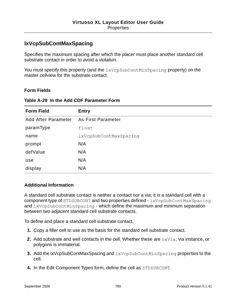
Virtuoso XL Layout Editor User GuideProperties
lxVcpSubContMaxSpacing
Specifies the maximum spacing after which the placer must place another standard cellsubstrate contact in order to avoid a violation.
You must specify this property (and the lxVcpSubContMinSpacing property) on themaster cellview for the substrate contact.
Form Fields
Additional Information
A standard cell substrate contact is neither a contact nor a via; it is a standard cell with acomponent type of STDSUBCONT and two properties defined - lxVcpSubContMaxSpacingand lxVcpSubContMinSpacing - which define the maximum and minimum separationbetween two adjacent standard cell substrate contacts.
To define and place a standard cell substrate contact,
1. Copy a filler cell to use as the basis for the standard cell substrate contact.
2. Add substrate and well contacts in the cell. Whether these are oaVia, via instance, orpolygons is immaterial.
3. Add the lxVcpSubContMaxSpacing and lxVcpSubContMinSpacing properties to thecell.
4. In the Edit Component Types form, define the cell as STDSUBCONT.
Table A-29 In the Add CDF Parameter Form
Form Field Entry
Add After Parameter As First Parameter
paramType float
name lxVcpSubContMaxSpacing
prompt N/A
defValue N/A
use N/A
display N/A
September 2006 780 Product Version 5.1.41

Virtuoso XL Layout Editor User GuideProperties
5. Run the placer with the Insert Substrate Contacts option switched on.
The placer fills any gaps between placed cells with the specified standard cell substratecontacts.
lxVcpSubContMaxSpacing is the spacing after which the placer must place anotherstandard cell substrate contact in order to prevent a violation;lxVcpSubContMinSpacing is the minimum spacing between two consecutivestandard cell substrate contacts.
September 2006 781 Product Version 5.1.41
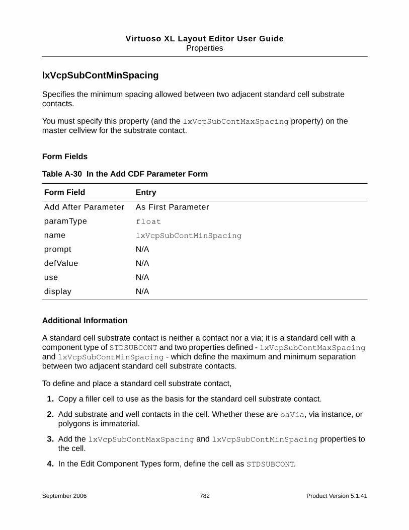
Virtuoso XL Layout Editor User GuideProperties
lxVcpSubContMinSpacing
Specifies the minimum spacing allowed between two adjacent standard cell substratecontacts.
You must specify this property (and the lxVcpSubContMaxSpacing property) on themaster cellview for the substrate contact.
Form Fields
Additional Information
A standard cell substrate contact is neither a contact nor a via; it is a standard cell with acomponent type of STDSUBCONT and two properties defined - lxVcpSubContMaxSpacingand lxVcpSubContMinSpacing - which define the maximum and minimum separationbetween two adjacent standard cell substrate contacts.
To define and place a standard cell substrate contact,
1. Copy a filler cell to use as the basis for the standard cell substrate contact.
2. Add substrate and well contacts in the cell. Whether these are oaVia, via instance, orpolygons is immaterial.
3. Add the lxVcpSubContMaxSpacing and lxVcpSubContMinSpacing properties tothe cell.
4. In the Edit Component Types form, define the cell as STDSUBCONT.
Table A-30 In the Add CDF Parameter Form
Form Field Entry
Add After Parameter As First Parameter
paramType float
name lxVcpSubContMinSpacing
prompt N/A
defValue N/A
use N/A
display N/A
September 2006 782 Product Version 5.1.41
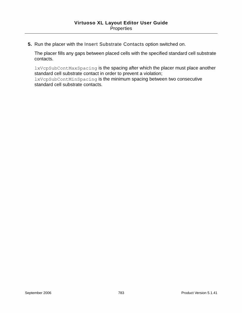
Virtuoso XL Layout Editor User GuideProperties
5. Run the placer with the Insert Substrate Contacts option switched on.
The placer fills any gaps between placed cells with the specified standard cell substratecontacts.
lxVcpSubContMaxSpacing is the spacing after which the placer must place anotherstandard cell substrate contact in order to prevent a violation;lxVcpSubContMinSpacing is the minimum spacing between two consecutivestandard cell substrate contacts.
September 2006 783 Product Version 5.1.41
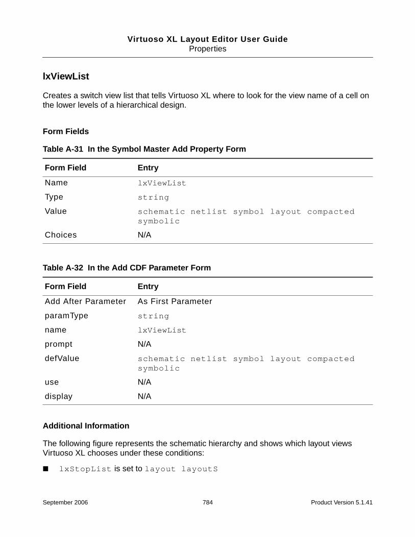
Virtuoso XL Layout Editor User GuideProperties
lxViewList
Creates a switch view list that tells Virtuoso XL where to look for the view name of a cell onthe lower levels of a hierarchical design.
Form Fields
Additional Information
The following figure represents the schematic hierarchy and shows which layout viewsVirtuoso XL chooses under these conditions:
■ lxStopList is set to layout layoutS
Table A-31 In the Symbol Master Add Property Form
Form Field Entry
Name lxViewList
Type string
Value schematic netlist symbol layout compactedsymbolic
Choices N/A
Table A-32 In the Add CDF Parameter Form
Form Field Entry
Add After Parameter As First Parameter
paramType string
name lxViewList
prompt N/A
defValue schematic netlist symbol layout compactedsymbolic
use N/A
display N/A
September 2006 784 Product Version 5.1.41

Virtuoso XL Layout Editor User GuideProperties
■ lxViewList is set to schematic cmos.sch
The chosen layout views are shown with thick-line boxes.
In this figure, as Virtuoso XL builds the layout, it looks at each symbol in the Top Cell.
The mux cell has no view listed in the stop list; therefore, Virtuoso XL goes to the view list andswitches into the Mux schematic. All devices in the Mux schematic have views that are in thestop list; therefore, Virtuoso XL places those views.
The AND cell has a view listed in the stop list; therefore, Virtuoso XL places that view andnever switches into the view list.
schematic
Top Cell
layoutAND
cmos.schschematic
Mux
symbolsymbol
layoutS
PMOS
symbol
layout
PMOSNMOS
symbol
layout
symbol
layout
symbol
layout
PMOS
symbol
layout
PMOSNMOS
symbol
layout
symbol
layout
symbol
layout
NMOS NMOS
chosen layout view
September 2006 785 Product Version 5.1.41

Virtuoso XL Layout Editor User GuideProperties
mfactor
Defines a one-to-many parallel relationship between a device in a schematic and multipleinstances of the device in the layout.
Form Fields
Additional Information
The multiplication factor (mfactor) is a parameter that defines a one-to-many parallelrelationship between a device in a schematic and multiple instances of the device in thelayout.
Table A-33 In the Symbol Master Add Property Form
Form Field Entry
Name mfactor
Type string
Value
Choices N/A
Table A-34 In the Add CDF Parameter Form
Form Field Entry
Add After Parameter As First Parameter
paramType string
name mfactor
prompt N/A
defValue
use N/A
display N/A
September 2006 786 Product Version 5.1.41

Virtuoso XL Layout Editor User GuideProperties
The mfactor property and mfactorSplit environment variable both work hierarchically.Any instance in the connectivity source hierarchy can have these properties, and themultiplicity is computed from the hierarchical path.
You can use the mfactorSplit environment variable to control whether the mfactor producesmultiple layout devices or not. Set the lxMfactorSplit property on a given instance to overridethe global value set by the mfactorSplit environment variable.
Note: You cannot use multiplication factors with components that cannot be used in parallel,such as voltage sources.
Naming Convention
Devices specified using the mfactor property in the schematic (and those that are folded inthe layout) are named instName.integer in the layout.
For example, if you have a schematic instance named P0 with
mfactor = 3
Top-level schematic
Lower-level schematic
Layout (showing incomplete nets)
np
n
np
n
|I0|Q9.2|I0|Q9.1
I0
September 2006 787 Product Version 5.1.41

Virtuoso XL Layout Editor User GuideProperties
the layout instances generated are named as follows.
Schematic Layout
P0 |P0.1|P0.2|P0.3
September 2006 788 Product Version 5.1.41
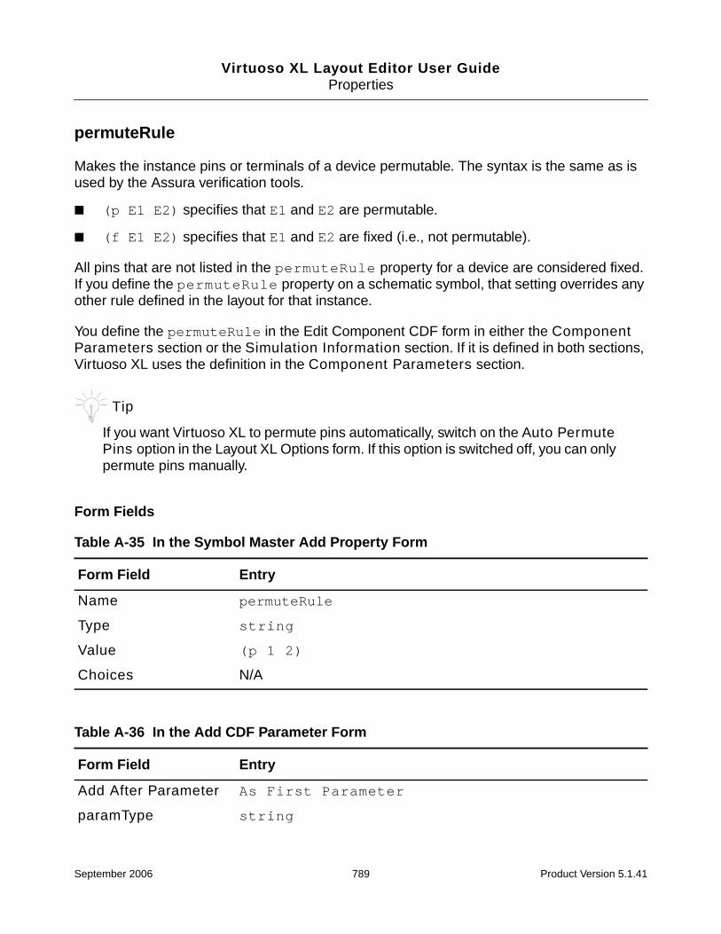
Virtuoso XL Layout Editor User GuideProperties
permuteRule
Makes the instance pins or terminals of a device permutable. The syntax is the same as isused by the Assura verification tools.
■ (p E1 E2) specifies that E1 and E2 are permutable.
■ (f E1 E2) specifies that E1 and E2 are fixed (i.e., not permutable).
All pins that are not listed in the permuteRule property for a device are considered fixed.If you define the permuteRule property on a schematic symbol, that setting overrides anyother rule defined in the layout for that instance.
You define the permuteRule in the Edit Component CDF form in either the ComponentParameters section or the Simulation Information section. If it is defined in both sections,Virtuoso XL uses the definition in the Component Parameters section.
Tip
If you want Virtuoso XL to permute pins automatically, switch on the Auto PermutePins option in the Layout XL Options form. If this option is switched off, you can onlypermute pins manually.
Form Fields
Table A-35 In the Symbol Master Add Property Form
Form Field Entry
Name permuteRule
Type string
Value (p 1 2)
Choices N/A
Table A-36 In the Add CDF Parameter Form
Form Field Entry
Add After Parameter As First Parameter
paramType string
September 2006 789 Product Version 5.1.41
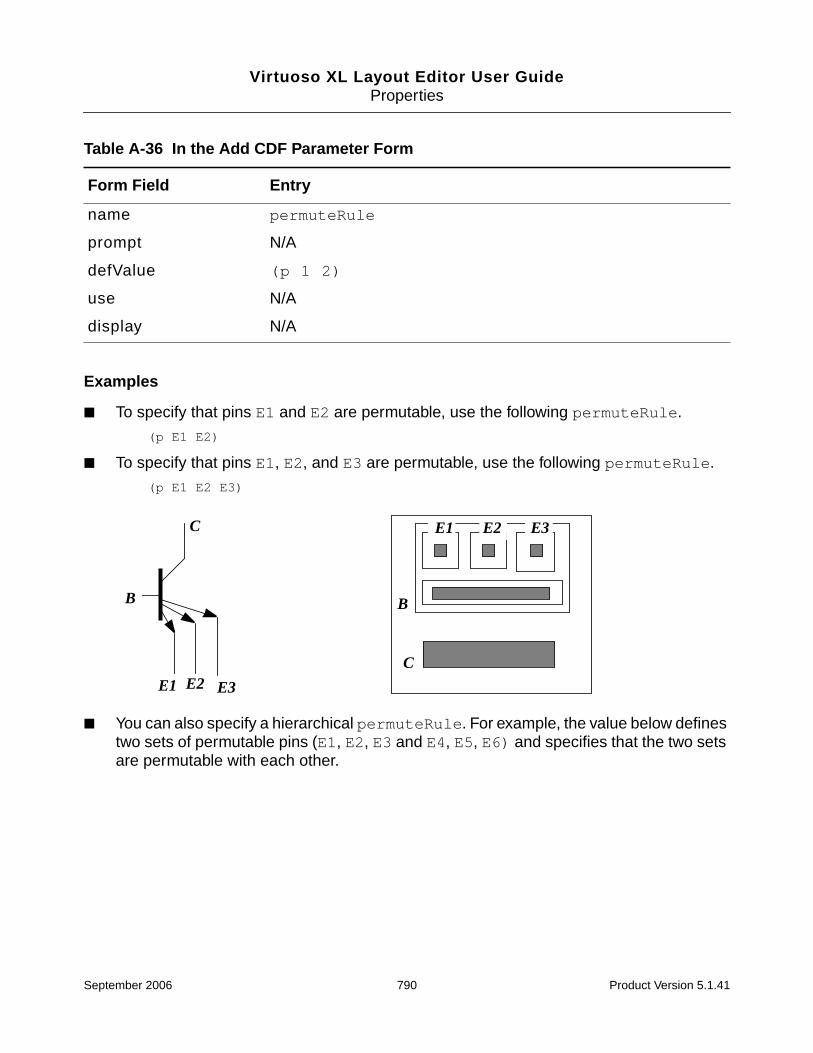
Virtuoso XL Layout Editor User GuideProperties
Examples
■ To specify that pins E1 and E2 are permutable, use the following permuteRule.
(p E1 E2)
■ To specify that pins E1, E2, and E3 are permutable, use the following permuteRule.
(p E1 E2 E3)
■ You can also specify a hierarchical permuteRule. For example, the value below definestwo sets of permutable pins (E1, E2, E3 and E4, E5, E6) and specifies that the two setsare permutable with each other.
name permuteRule
prompt N/A
defValue (p 1 2)
use N/A
display N/A
Table A-36 In the Add CDF Parameter Form
Form Field Entry
E1 E2 E3
B
C E1 E2 E3
B
C
September 2006 790 Product Version 5.1.41

Virtuoso XL Layout Editor User GuideProperties
(p (p E1 E2 E3) (p E4 E5 E6))
■ The following permuteRule value defines two sets of permutable pins (E1, E2, E3 andE4, E5, E6) and specifies that the two sets are not permutable with each other.
(f (p E1 E2 E3) (p E4 E5 E6))
Macros
To avoid entering long lists of permutable pins for the permuteRule property, you can usethe following macro notations.
■ (f ALL), which means that all of the pins in the cell are fixed
■ (p ALL), which means that all of the pins in the cell are permutable
■ Range indications, where pins are numbered or sorted as in bus notations.
For example, the notation
(p A<0:3> B<4:7>)
is equivalent to
(p A<0> A<1> A<2> A<3> B<4> B<5> B<6> B<7>)
The notation
(p (f A<0:3>) (f B<4:7>))
defines two sets of fixed pins (A<0:3> and B<4:7>) which are permutable with eachother
You can also express range indications in descending order
(p A<3:0> B<7:4>)
E4
E5E6
E1
E2
E3
September 2006 791 Product Version 5.1.41

Virtuoso XL Layout Editor User GuideProperties
sfactor
Defines a one-to-many relationship between a device in a schematic and multiple series-connected instances in the layout.
Form Fields
Additional Information
The series-connection factor (sfactor) is a parameter that can be used to define a one-to-many relationship between a device in a schematic and multiple instances in seriesconnection in the layout. The sfactor property can be applied to two or three terminalresistors, capacitors, and inductors. You set the value of the sfactor property (called s orS, unless you change it in the Layout XL Options form) to the number of layout devices you
Table A-37 In the Symbol Master Add Property Form
Form Field Entry
Name sfactor
Type integer, string, floating point number, orexpression,
Value user defined
Choices N/A
Table A-38 In the Add CDF Parameter Form
Form Field Entry
Add After Parameter As First Parameter
paramType integer, string, floating point number, orexpression
name sfactor
prompt N/A
defValue user defined
use N/A
display N/A
September 2006 792 Product Version 5.1.41
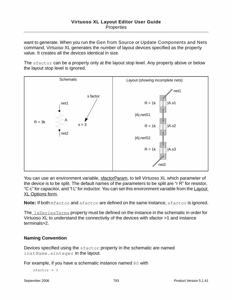
Virtuoso XL Layout Editor User GuideProperties
want to generate. When you run the Gen from Source or Update Components and Netscommand, Virtuoso XL generates the number of layout devices specified as the propertyvalue. It creates all the devices identical in size.
The sfactor can be a property only at the layout stop level. Any property above or belowthe layout stop level is ignored.
You can use an environment variable, sfactorParam, to tell Virtuoso XL which parameter ofthe device is to be split. The default names of the parameters to be split are “r R” for resistor,“C c” for capacitor, and “l L” for inductor. You can set this environment variable from the LayoutXL Options form.
Note: If both mfactor and sfactor are defined on the same instance, sfactor is ignored.
The lxSeriesTerms property must be defined on the instance in the schematic in order forVirtuoso XL to understand the connectivity of the devices with sfactor >1 and instanceterminals>2.
Naming Convention
Devices specified using the sfactor property in the schematic are namedinstName.sinteger in the layout.
For example, if you have a schematic instance named R0 with
sfactor = 3
net2
net2
|A.s1
s = 3R = 3k
Schematic Layout (showing incomplete nets)
A
net1
R = 1k
R = 1k
R = 1k
net1
|A.s2
|A.s3
|A|.netS2
|A|.netS1
s factor
September 2006 793 Product Version 5.1.41

Virtuoso XL Layout Editor User GuideProperties
the layout instances generated are named as follows.
Schematic Layout
R0 |R0.s1|R0.s2|R0.s3
September 2006 794 Product Version 5.1.41

Virtuoso XL Layout Editor User GuideProperties
vxlInstSpacingDir
Assigns automatic spacing properties to pins of instances. If these pins are on different netsor the pins cannot abut for any reason (for example, they are not assigned abutmentproperties), the software automatically separates the instances by the distance and in thedirection you specify.
Form Fields
Additional Information
If you want automatic spacing to apply to Cadence® SKILL language or technology fileparameterized cells (pcells), you can enter these properties in SKILL to add the spacingproperties to the pins.
Table A-39 In the Symbol Master Add Property Form
Form Field Entry
Name vxlInstSpacingDir
Type list
Value left right top bottom
Choices N/A
Table A-40 In the Add CDF Parameter Form
Form Field Entry
Add After Parameter As First Parameter
paramType list
name vxlInstSpacingDir
prompt N/A
defValue left right top bottom
use N/A
display N/A
September 2006 795 Product Version 5.1.41

Virtuoso XL Layout Editor User GuideProperties
If you want automatic spacing to apply to standard cells, you can also use the Virtuoso layouteditor to enter properties on the pins.
If the vxlInstSpacingRule value is different for two pins affected by Auto Space, thelarger of the two values is used; if the value is defined for only one of two pins affected byAuto Space, the defined value is used.
➤ To activate automatic spacing, turn on Auto Space in the Layout XL Options form (onis the default).
You can use the Virtuoso layout editor user interface to enter properties on the pins in thesame way that you enter the permuteRule properties.
To add the access direction to the pin:
property value type valid values
----------------- ---------- ----------------------------
vxlInstSpacingDir skill list one or more of the followingstrings in the list:"left" "right" "top" "bottom"
with Auto Space turned off
0.6
vxlInstSpacingDirvalue = rightvxlInstSpacingRulevalue = 0.6
vxlInstSpacingDirvalue = leftvxlInstSpacingRule value = 0.5
with Auto Space turned on
vxlInstSpacingDirvalue = right, leftvxlInstSpacingRulevalue = 0.6
vxlInstSpacingDirvalue = right, leftvxlInstSpacingRule value = 1.0
1.0
September 2006 796 Product Version 5.1.41

Virtuoso XL Layout Editor User GuideProperties
vxlInstSpacingRule
Defines a spacing offset when pins are on a different net.
Form Fields
Additional Information
A user defined function, called abutFunction, can be used to define a spacing offset whenpins are on a different net. When you set the vxlInstSpacingRule to float, two pins of thesame abutment class and different nets are pushed apart a distance equal to the maximumvalues of the two vxlInstSpacingRule pins. To control the abutment spacing set thevxlInstSpacingRule to string abutFunction.
Note: The abutFunction is not the name of your custom abutment function, but is the propertythat is set to the name of your abutment function.
Table A-41 In the Symbol Master Add Property Form
Form Field Entry
Name vxlInstSpacingRule
Type float
Value number greater than 0
Choices N/A
Table A-42 In the Add CDF Parameter Form
Form Field Entry
Add After Parameter As First Parameter
paramType float
name vxlInstSpacingRule
prompt N/A
defValue number greater than 0
use N/A
display N/A
September 2006 797 Product Version 5.1.41
Virtuoso XL Layout Editor User GuideProperties
dbReplaceProp(sObj~>dbId "abutFunction" "string" "myCustomAbutmentFunction")
dbReplaceProp(sObj~>dbId "vxlInstSpacingRule" "string" "abutFunction")
You can write your own spacing function for the two instances involved. For example,myCustomSpacingFunc ( )is to be called in the body of the user defined abutmentfunction (abutFunction). The myCustomSpacingFunc ( ) must return a float value tobe effective.
There are two numbers passed to the abutment function, the connection condition (1, 2, or 3)and the abutment event (1, 2, 3, or 4). The connection condition (3) is for different nets. Thesequence for nonabuttable pins should be the same as for abuttable. The calling of theabutment function for adjusting the pcells (event 2) and then one to calculate the spacing ofthe resultant reference edges (event 4). This allows you to adjust the well or isolation on thepcell and then space the devices based on the reference edges.
To get the spacing offset when pins are on different nets add the following case in your customabutment function.
(4
if(instA~>w > 3.0 && instB~>w > 3.0
then
result = 3
else
result = 1
)
);; end of case 4
You can use the layout editor user interface to enter properties on the pins in the same waythat you enter the permuteRule properties.
If you need to add a variable spacing rule to the pin, set the vxlInstSpacingRule toabutFunction as shown below;
dbReplaceProp(sObj~>dbId "vxlInstSpacingRule" "string" "abutFunction")
The properties to set automatic spacing are listed below.
To add the spacing rule to the pin:
property value type valid values
----------------- ---------- ----------------------
vxlInstSpacingRule floating number greater than 0
pt number
September 2006 798 Product Version 5.1.41

Virtuoso XL Layout Editor User GuideProperties
September 2006 799 Product Version 5.1.41