vinidex hydro pvc-m - reece plumbing pvc-m introduction unplasticised poly vinyl chloride (pvc) has...
TRANSCRIPT
modified pvC for potable Water & irrigation ApplicationsAvailable in pipe sizes 100mm to 575mm series 1 & 2
imprOveD mAteriAl perFOrmAnCe
HYDrAuliC eFFiCienCY
liGHt WeiGHt
sYstem COmpAtiBilitY
vinidex Hydro® pvC-m
Quality ISO 9001Lic 570

limitation of liability
this product catalogue has been compiled by vinidex pty limited (“the Company”) to promote better understanding of the technical aspects of the Company’s products to assist users in obtaining from them the best possible performance. the product catalogue is supplied subject to acknowledgement of the following conditions:1. the product catalogue is protected by copyright and may not be copied or reproduced in any form or by any means in whole or in part without prior consent in writing by the Company. 2. product specifications, usage data and advisory information may change from time to time with advances in research and field experience. the Company reserves the right to make such changes at any time without further notice. 3. Correct usage of the Company’s products involves engineering judgements, which can not be properly made without full knowledge of all the conditions pertaining to each specific installation. the Company expressly disclaims all and any liability to any person whether supplied with this publication or not in respect of anything and all of the consequences of anything done or omitted to be done by any such person in reliance whether whole or part of the contents of this publication. 4. no offer to trade, nor any conditions of trading, are expressed or implied by the issue of content of this product catalogue. nothing herein shall override the Company’s Condition of sale, which may be obtained from the registered Office or any sales Office of the Company. 5. this product catalogue is and shall remain the property of the Company, and shall be surrendered on demand to the Company. 6. information supplied in this product catalogue does not override a job specification, where such conflict arises; consult the authority supervising the job. © Copyright vinidex pty limited.
viniDeX HYDrO® pvC-m
intrODuCtiOn 1
AppliCAtiOns 1
mAteriAl CHArACteristiCs 1
BeneFits 2
improved material performance 2
Hydraulic efficiency 2
light Weight 3
system Compatibility 3
product list 4
product Data 6
standards and Dimensions 6
DesiGn 7
system life 7
Hydraulic 7
structural 7
Flow Chart – vinidex Hydro® pvC-m pressure pipe series 1 – pn 6, pn 9 and pn 12
9
Flow Chart – vinidex Hydro® pvC-m pressure pipe series 2 – pn 6, pn 9, pn 12 and pn 16
10
Fatigue 11
Fatigue Design procedure 12
temperature 12
installation 13

Hydro® pvC-m
intrODuCtiOn
unplasticised poly vinyl Chloride (pvC) has established an enviable reputation as the material of choice for infrastructure applications in both pressure and non- pressure pipelines.
With a service history dating back to the 1930’s, industry has recognised the many benefits of pvC, material stability, corrosion resistance, high strength to weight ratio, ease of handling and instal lation and excellent flow characteristics.
Development in plastics over the last 50 years has been rapid with developments in pipeline systems being at the forefront. the result is an improved pvC material, modified poly vinyl Chloride or pvC-m. pvC-m is manufactured by vinidex under the trade name vinidex Hydro®.
vinidex Hydro® pvC-m extends the proven benefits of pvC pipes with enhancements in fracture behaviour and hydraulic efficiency. A new standard has been developed for vinidex Hydro® pvC-m, As/nZs 4765:2007 “modified pvC (pvC-m) pipes for pressure applications”.
AppliCAtiOns
vinidex Hydro® pvC-m is suitable for pressure applications for potable water, irrigation, fire fighting and general industrial applications in the temperature range 0 to 50° Celsius. vinidex Hydro® is available in two diameter groups, series 1 and series 2, which denote the outside diameter of each group. in general the irrigation industry uses series 1 and the potable water industry uses series 2.
vinidex Hydro® is available in sizes from Dn 100 to 575 and pressure classes 6, 9, 12, 15, 16, 18 and 20 dependent on pipe series and diameter.
vinidex Hydro® pvC-m
mAteriAl CHArACteristiCs
pvC is formed by the combination of chlorine, carbon and hydrogen in the form of polymer chains. pvC-m is formed by the addition of compatible modifying agents to the pvC matrix, forming an alloy rather than a copolymer. the addition of modifying agents increases the ductility while virtually retaining the same material strength.
the modifying agents significantly improve toughness and impact properties with resistance to crack growth a key performance requirement. the change in material matrix gives greater ductile behaviour and thus ena-bles the factor of safety to be lower than pvC. short and long term tests on vinidex Hydro® pressure pipes have demonstrated consistently ductile behaviour, particularly in the presence of notches. the reduced factor of safety enables higher allowable stress levels, reduced wall thickness providing greater hydraulic efficiency.
stabilisers are an integral component of pvC-m manufacture, maintaining thermal stability during the extrusion process. All vinidex pressure pipes including vinidex Hydro® pvC-m are manufactured using Calcium Zinc stabilisers.
As/nZs 4765:2007 details a broad range of material acceptance tests which guarantee achievement of ductile material characteristics.
1
Hydro® pvC-m
BeneFits
improved material performance
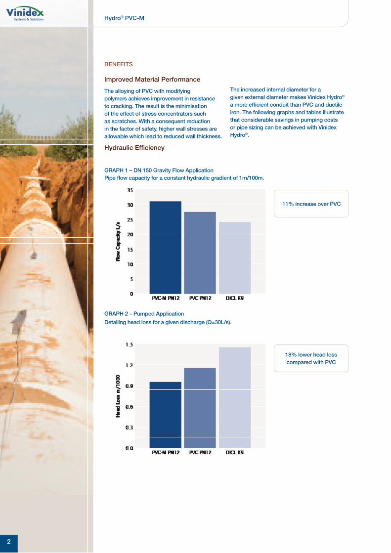
the alloying of pvC with modifying poly mers achieves improvement in resistance to cracking. the result is the minimisation of the effect of stress concentrators such as scratches. With a consequent reduction in the factor of safety, higher wall stresses are allowable which lead to reduced wall thickness.
Hydraulic efficiency
11% increase over pvC
18% lower head loss compared with pvC
the increased internal diameter for a given external diameter makes vinidex Hydro® a more efficient conduit than pvC and ductile iron. the following graphs and tables illustrate that considerable savings in pumping costs or pipe sizing can be achieved with vinidex Hydro®.
GrApH 1 – Dn 150 Gravity Flow Application pipe flow capacity for a constant hydraulic gradient of 1m/100m.
GrApH 2 – pumped Application
Detailing head loss for a given discharge (Q=30l/s).
2

Hydro® pvC-m
tABle 1 – Comparative Flow rates (l/s)
Based on velocity of 2m/s
series 2 pvC DiCl K9 pvC-m% increase
over pvC over DiCl
100/12 18.5 15.1 19.9 7.6 31.8
100/16 17.1 15.1 18.9 10.5 25.2
150/12 39.2 36.8 42.4 8.2 15.2
150/16 36.3 36.8 40.3 11 9.5
200/12 68.8 65.4 72.7 5.7 11.2
200/16 64.2 65.4 69.1 7.6 5.7
225/12 85.6 82.4 90.7 6 10.1
225/16 80.1 82.4 86.2 7.6 4.6
250/12 104 103 110 5.8 6.8
250/16 97.5 103 105 7.7 1.9
300/12 152 154 161 5.9 4.5
300/16 142 154 153 7.7 -0.6
375/6 257 240 259 0.8 7.9
375/9 244 240 255 4.5 6.3
375/12 232 240 245 5.6 2.1
375/16 216 240 235 8.8 -2.1
450/6 364 343 367 0.8 7
450/9 364 343 361 4.3 5.2
450/12 328 343 347 5.8 1.2
light Weight
pvC is already recognised as the lightest and easiest of pipeline materials to handle. vinidex Hydro® further increases this advantage. Depending on size and class, weight savings in excess of 10% over pvC is available.
system Compatibility
Whether supplied in series 1 for the irrigation industry or series 2 for the water industry, vinidex Hydro® is fully compatible with existing pipeline systems with the full range of valves and fittings available.
BeneFits
3

Hydro® pvC-m
prODuCt list
4
vinidex Hydro® pvC-m series 1 – rrJ
vX Code DescriptionApprox. mass
(kg/length)
17035 100 pn9 rrJ 6m 10
17045 100 pn12 rrJ 6m 13
17080 150 pn9 rrJ 6m 19
17090 150 pn12 rrJ 6m 24
17100 200 pn6 rrJ 6m 31
17110 200 pn9 rrJ 6m 37
17120 200 pn12 rrJ 6m 48
17135 225 pn9 rrJ 6m 45
17140 225 pn12 rrJ 6m 59
17145 250 pn6 rrJ 6m 50
17150 250 pn9 rrJ 6m 57
17155 250 pn12 rrJ 6m 74
17160 300 pn6 rrJ 6m 62
17165 300 pn9 rrJ 6m 71
17170 300 pn12 rrJ 6m 93
17175 375 pn6 rrJ 6m 101
17180 375 pn9 rrJ 6m 115
17174 375 pn12 rrJ 6m 150
17171 450 pn6 rrJ 6m 153
17172 450 pn9 rrJ 6m 179
17173 450 pn12 rrJ 6m 234
17415 500 pn6 rrJ 6m 201
17416 500 pn9 rrJ 6m 235
17417 500 pn12 rrJ 6m 308
17418 575 pn6 rrJ 6m 252
17419 575 pn9 rrJ 6m 295
17420 575 pn12 rrJ 6m 388
vinidex Hydro® pvC-m series 1 – sCJ
vX Code DescriptionApprox. mass
(kg/length)
17040 100 pn9 sCJ 6m 10
17050 100 pn12 sCJ 6m 13
17085 150 pn9 sCJ 6m 19
17095 150 pn12 sCJ 6m 24
17115 200 pn9 sCJ 6m 37
17125 200 pn12 sCJ 6m 48

Hydro® pvC-m
vinidex Hydro® pvC-m series 2 – rrJ
vX Code DescriptionApprox. mass
(kg/length)
17181 100 pn12 rrJ 6m 15
17182 100 pn16 rrJ 6m 19
17183 100 pn18 rrJ 6m 21
17184 100 pn20 rrJ 6m 23
17185 150 pn12 rrJ 6m 30
17186 150 pn16 rrJ 6m 39
17187 150 pn18 rrJ 6m 44
17188 150 pn20 rrJ 6m 48
17189 200 pn12 rrJ 6m 52
17190 200 pn16 rrJ 6m 66
17194 225 pn16 rrJ 6m 82
17197 250 pn12 rrJ 6m 79
17198 250 pn16 rrJ 6m 100
17201 300 pn12 rrJ 6m 116
17202 300 pn16 rrJ 6m 145
17206 375 pn9 rrJ 6m 130
17207 375 pn12 rrJ 6m 170
17208 375 pn16 rrJ 6m 222
17411 450 pn6 rrJ 6m 162
17412 450 pn9 rrJ 6m 190
17413 450 pn12 rrJ 6m 249
17414 450 pn16 rrJ 6m 325
prODuCt list
5

Hydro® pvC-m
tABle 3 – Dimensions for vinidex Hydro® pvC-m pipes series 2
normal size Dn
Outside Diameter mean OD
pn6 pn9 pn12 pn16
Dm min Dn max tmin tmax tmin tmax tmin tmax tmin tmax
100 121.7 122.1 – – – – 4.1 5.3 5.4 6.8
150 177.1 177.6 – – – – 5.9 7.3 7.8 9.5
200 231.9 232.6 – – – – 7.7 9.4 10.2 12.3
225 258.9 259.6 – – – – 8.6 10.4 11.4 13.7
250 285.8 286.6 – – – – 9.5 11.5 12.5 14.9
300 344.9 345.8 – – – – 11.5 13.8 15.1 17.9
375 425.7 426.7 9.1 11.0 10.7 12.9 14.2 16.9 18.7 21.1
450 506.5 507.5 10.8 13.0 12.7 15.2 16.8 19.9 22.2 26.1
prODuCt DAtA
standards and Dimensions
vinidex Hydro® pipes are manufactured in accordance with As/nZs 4765:2007 with standards mark numbers 2560, 2561, 2562 and 2563.
As/nZs 4765:2007 provides two manu facturing series relating to the outside diameter of the pipe. series 1 is isO compatible
outside diameters (mostly metric) and series 2 is ductile iron compatible outside diameters.
refer to table 2 and 3 for dimensional data. in general, the irrigation industry uses series 1 and the potable water industry uses series 2. vinidex Hydro® is available in both series 1 and 2 to suit these industries.
tABle 2 – Dimensions for vinidex Hydro® pvC-m pipes series 1
normal size Dn
Outside Diameter mean OD pn6 pn9 pn12
Dm min Dn max tmin tmax tmin tmax tmin tmax
100 114.1 114.5 – – 2.9 3.9 3.8 4.9
125 140.0 140.4 – – 3.6 4.7 4.7 6.0
150 160.0 160.5 – – 4.1 5.3 5.3 6.6
200 225.0 225.6 4.8 6.1 5.7 7.1 7.5 9.2
225 250.0 250.7 – – 6.3 7.8 8.3 10.1
250 280.0 280.8 6.0 7.4 7.1 8.7 9.3 11.2
300 315.0 315.9 6.7 8.3 7.9 9.6 10.5 12.6
375 400.0 401.0 8.6 10.4 10.1 12.2 13.3 15.8
450 500.0 501.0 10.7 12.9 12.6 15.0 16.6 19.6
500 560.0 561.0 12.0 14.3 14.1 16.8 18.6 21.9
575 630.0 631.0 13.4 16.0 15.8 18.7 20.9 24.6
6
Hydro® pvC-m
DesiGn
system life
it is a common misconception that plastics pipes have a design life of 50 years, arising from the use of regression curves and adoption of the 50 year point for classification purposes.
in relation to hydrostatic stress analysis and pipe life, As/nZs 4765 states the following: “the analysis adopts the 50 years extrapolation point on the regression curve as the reference for design purposes. this is consistent with long standing international practice.
it should not be taken that either –
(a) the pipes weaken with time; or(b) the predicted life is 50 years
Actual system life is dependent on manufacture, transport, handling, installation, operation, protection from third party damage and other external factors. For water supply applications, the actual life can logically be expected to be well in excess of 100 years before major rehabilitation is required.”
Hydraulic
the principles of closed conduit flow and behaviour of fluids is well established. vinidex recommend the use of the Colebrook-White formula for the analysis of flow parameters for vinidex Hydro® pipe. A roughness coefficient k = 0.003mm is recommended and all computations are based on water at 20° C.
Additional background information on hydraulic design can be found in the vinidex Water supply manual for pvC pipe systems. Computational assistance is available in the vinidex program “Fluff”, which can provide an analysis of a wide range of pipeline materials.
Flow Charts for vinidex vinidex Hydro® series 1 and series 2 are shown on pages 9 and 10.
structural
under general pressure pipe installation conditions, including under roads, detailed calculations predicting pipe performance are not necessary. Following an extensive study of installed pipe performance, a joint project conducted by the european plastic pipe and Fitting Association (teppFA) and independent experts concluded that final deflection of pipes was controlled by the settlement of the soil after installation.
Where installation was controlled, or self-compacting granular material was used, pipe deflections were consistently low regardless of installation depth and traffic or other loads.
For unusual conditions, or depths greater than 6 metres, design calculations may be performed in accordance with As/nZs 2566.1. the structural design aspects of buried flexible pipes to be considered are vertical deflection, ring bending strain and buckling.
Differential pressure conditions between the inside and outside of a pipe can cause a pipe to buckle inwards leading to collapse. such conditions can arise from high external loading or negative internal pressure transients as a consequence of pipeline operating conditions. A pipes resistance to buckling is directly proportional to ring bending stiffness.
As pvC-m pipes have reduced wall thickness compared to pvC of the same pn rating, the ring bending stiffness is significantly reduced. Consequently the resistance to buck-ling of pvC-m is also significantly reduced. Designers should be aware of pipeline operating criteria and consult appropriate design material including As/nZs 2566.1:1998 to ensure the suitability of pvC-m in such applications.
table 4 and Graph 3 of critical collapse pressures are based on short term loading of an unsupported circular pipe and does not include a factor of safety. the choice of factor of safety depends on the certainty of operation parameters and should be nominated by the designer.
For buried pipes the soil surround provides additional support against buckling providing the minimum cover height exceeds 500mm. such support can only be realised where the embedment is properly placed and compacted with no voids around the pipe and the embedment cannot subsequently be removed or leached away.
in general where sustained negative pressures or full vacuum conditions are likely to occur, e.g. suction lines, vinidex recommends that pn 12 pipe or higher be selected based on an appropriate factor of safety against buckling.
7

Hydro® pvC-m
tABle 4 – unsupported Collapse pressures (kpa)short term loading at 20°C.
pn6 pn9 pn12
pvC-m all sizes 73 121 288
pvC ≤ Dn150 155 522 1236
pvC < Dn150 111 373 884
GrApH 3 – unsupported Collapse pressures for Dn150 pipeshort term loading at 20°C.
pvC-m
pvC
DesiGn
8

Hydro® pvC-m
DesiGn
FlOW CHArt – vinidex Hydro® pvC-m pressure pipe series 1 pn6, pn9 and pn12
9

Hydro® pvC-m
DesiGn
FlOW CHArt – vinidex Hydro® pvC-m pressure pipe series 2 pn6, pn9, pn12 and pn16
10

Hydro® pvC-m
DesiGn
Fatigue
materials subject to repetitive or cyclic loads will fail at lower stress levels than materials subject to constant load. this is known as fatigue failure. For thermoplastics pipe materials, fatigue only becomes a design parameter when very high numbers of cycles are applied.
the behaviour of thermoplastic materials in cyclic operation conditions has been extensively studied. vinidex has developed an appropriate design procedure for such applications.
the two design parameters are the magnitude of the stress range and the frequency of the application, leading to the calculation of the number of cycles applied over the design life of the pipeline. in cases where lifetime cycles exceed 26,000, a higher class of the pipe may be required than indicated by the static or maximum pressure.
extensive studies into the fatigue behaviour of thermoplastics have been used to establish a relationship between stress range, defined as the difference between maximum and mini-mum stress (see Figure 1) and the number of cycles to failure. this relationship yields a load factor which is applied to the operating pres-sure to enable the selection of the appropriate class of pipe.
the approach adopted by vinidex is conservative recognising that the experimental data demonstrates a degree of scatter. this ensures an appropriate factor of safety given potential changes in the pipeline operating conditions over the life of the pipe and other operational conditions such as installation and maintenance standards.
For simplicity, the pressure range is defined as the maximum pressure minus the minimum pressure including all transients experienced by the system during normal oper-ations as per Figure 1. the effect of accidental conditions such as power failure may be excluded. Figure 1 illustrates the definition of a cycle as a repetitive event. in some cases the cycle pattern may be complex and it may be necessary to consider the contribution of secondary cycles.
For more detailed background information on the fatigue design of thermoplastic pipe includ-ing examples and a full list of references, consult vinidex technical notes vX-tn-4J and vX-tn-4H.
note that in fatigue loading applications, the maximum pressure in a cycle should not exceed the static pressure rating of the pipe. Figure 2 and table 5 provide graphical and numerical values of the recommended fatigue load factors.
FiGure 1 – pressure Cycle
11

Hydro® pvC-m
DesiGn
Fatigue Design procedure
to select the appropriate pipe class for fatigue loading, the following procedure should be adopted:
1. estimate the likely pressure range, ∆p i.e. the maximum pressure minus the minimum pressure.
2. estimate the frequency or the number of cycles per day, which are expected to occur.
3. Determine the required service life and calculate the total number of cycles which will occur in the pipe lifetime.
4. using table 5 or Figure 2, look up the fatigue load factor for the appropriate number of cycles.
5. Divide the pressure range by the fatigue load factor to obtain an equivalent operating pressure.
6. use the equivalent operating pressure to determine the class of pipe required.
FiGure 2 – Fatigue load Factors for pvC-m pipes
tABle 5 – Fatigue load Factors by number of Cycles
total cyclesApprox no. cycles/day for 100 year life
pvC-m Fatigue load Factors
26,400 1 1.00
100,000 3 0.67
500,000 14 0.41
1,000,000 27 0.33
5,000,000 137 0.21
10,000,000 274 0.17
50,000,000 1370 0.10
tABle 6 – temperature rating of vinidex Hydro® pvC-m pipesmaximum Allowable pressure (mpa).
temperature °C≤ 25 30 35 40 45 50
pn6 0.60 0.54 0.48 0.42 0.36 0.30
pn9 0.90 0.81 0.71 0.63 0.54 0.45
pn12 1.20 1.08 0.96 0.84 0.71 0.60
pn16 1.60 1.44 1.28 1.12 0.96 0.80
pn18 1.80 1.62 1.44 1.26 1.08 0.90
pn20 2.00 1.80 1.60 1.40 1.20 1.00
temperature
the nominal working pressure rating of vinidex Hydro® pipes is determined at 20°C. However, vinidex Hydro® pipes are suitable for use at temperatures up to 50°C. Where the service temperature exceeds 20°C, use table 6 to determine appropriate pipe class.
12

Hydro® pvC-m
instAllAtiOn
vinidex recommend that vinidex Hydro® pvC-m pipes are constructed in accordance with As 2032 – installation of pvC pipe systems and the vinidex Water supply manual.
installation techniques for vinidex vinidex Hydro® pipes are similar to those used for standard pvC pipes and the same degree of care and caution must be exercised. note that the thinner wall of vinidex vinidex Hydro® pipes means that they will experience higher lateral loads and care should be taken to ensure that the pipe is fully supported.
Quality non-cohesive material should be used for pipe bedding, side support and overlay. in general 1° deflection for rubber ring joints, is available at each socket-spigot joint. the pipe side support material should be placed evenly on both sides of the pipeline to two thirds the height of the pipe diameter and compacted by hand tamping.
side fill material should be worked under the sides of the pipe to eliminate all voids and provide maximum pipe haunching. the pipe overlay material should be levelled and compacted in layers to a minimum height of 150mm above the crown of the pipe or as specified.
For above ground installations the support spacings recommended in As 2032 can also be used for vinidex Hydro® pipes. these support spacing result in negligible deflection in pvC pipes full of water. For pvC-m pipes supported at these intervals, the stress levels in the pipe wall are still within acceptable limits.
However, for the same class of pipe, deflection between the supports will be in-creased by around 50%. since deflections are very small, this will not usually be of functional significance. the field testing procedures specified in As2032 and the vinidex Water supply manual should also be followed for vinidex Hydro® pipes.
13

AustrAliAn OperAtiOns
new south Wales
254 Woodpark rd smithfield nsW 2164
101 Byrnes rd nth Wagga Wagga nsW 2650
CustOmer serviCe
sales Hotline: 13 11 69 sales Fax: 13 24 43
email: [email protected] Web: www.vinidex.com.au
victoria
unit 1, 10 Duerdin st notting Hill viC 3168
231-245 st. Albans rd sunshine viC 3021
south Australia
9–11 Kaurna Ave edinburgh sA 5111
tasmania
15 thistle st sth launceston tAs 7250
Queensland
224 musgrave rd Coopers plains QlD 4108
49 enterprise Ave Bohle QlD 4816
northern territory
3846 marjorie st pinelands nt 0829
Western Australia
sainsbury rd O’Connor WA 6163
COrpOrAte HeAD OFFiCe
vinidex pty limitedABn 42 000 664 942
19–21 loyalty road north rocks, nsW 2151
tel: 02 8839 9006 Fax: 02 8839 9099
vin 186