video conferencing solutions for the integration with pstn - actfornet | huawei … ·...
TRANSCRIPT
Video Conferencing Solutions for the Integration with PSTN
1
Content
Introduction of AudioCodes MediaPack Series
Networking Architecture
Introduction of SoftCo
Introduction of AR G3 Series Router
1
2
3
4
Configuration Guide5
2
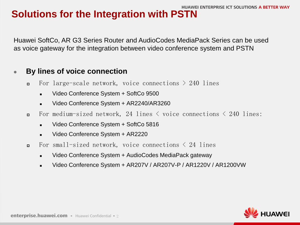
Solutions for the Integration with PSTN
By lines of voice connection
For large-scale network, voice connections > 240 lines
Video Conference System + SoftCo 9500
Video Conference System + AR2240/AR3260
For medium-sized network, 24 lines < voice connections < 240 lines:
Video Conference System + SoftCo 5816
Video Conference System + AR2220
For small-sized network, voice connections < 24 lines
Video Conference System + AudioCodes MediaPack gateway
Video Conference System + AR207V / AR207V-P / AR1220V / AR1200VW
Huawei SoftCo, AR G3 Series Router and AudioCodes MediaPack Series can be used
as voice gateway for the integration between video conference system and PSTN
3
SwitchManager
SwitchCenter
ResourceManager
MCU
Video Endpoint Video Endpoint
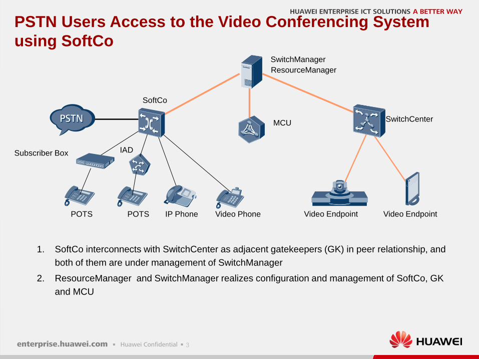
PSTN Users Access to the Video Conferencing System
using SoftCo
1. SoftCo interconnects with SwitchCenter as adjacent gatekeepers (GK) in peer relationship, and
both of them are under management of SwitchManager
2. ResourceManager and SwitchManager realizes configuration and management of SoftCo, GK
and MCU
SoftCo
POTS IP Phone Video Phone
Subscriber Box IAD
POTS
4
SwitchManager
AudioCodes
MediaPack
SwitchCenter
ResourceManager
MCU
Phone Phone Video Endpoint Video Endpoint
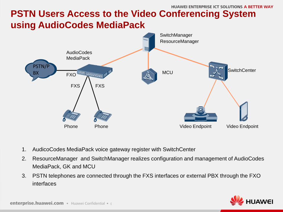
PSTN Users Access to the Video Conferencing System
using AudioCodes MediaPack
1. AudicoCodes MediaPack voice gateway register with SwitchCenter
2. ResourceManager and SwitchManager realizes configuration and management of AudioCodes
MediaPack, GK and MCU
3. PSTN telephones are connected through the FXS interfaces or external PBX through the FXO
interfaces
FXS
FXO
FXS
PSTN/PBX
5
SwitchManager
AR G3 Route
SwitchCenter
ResourceManager
MCU
Phone Phone Video Endpoint Video Endpoint
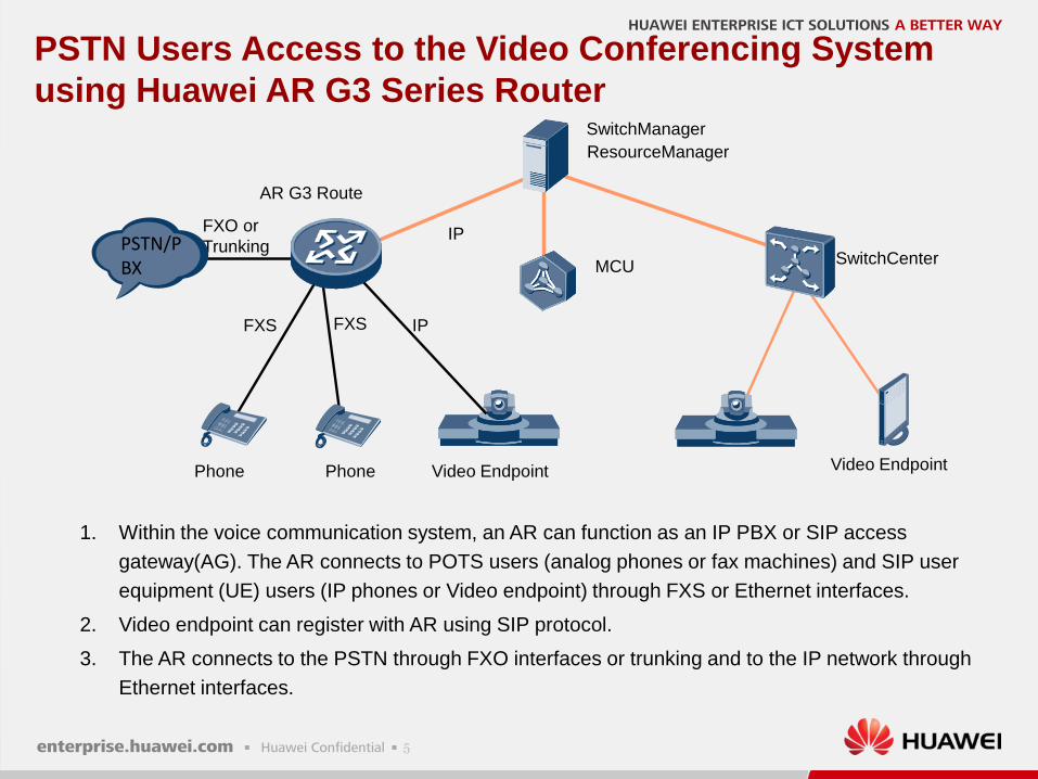
PSTN Users Access to the Video Conferencing System
using Huawei AR G3 Series Router
1. Within the voice communication system, an AR can function as an IP PBX or SIP access
gateway(AG). The AR connects to POTS users (analog phones or fax machines) and SIP user
equipment (UE) users (IP phones or Video endpoint) through FXS or Ethernet interfaces.
2. Video endpoint can register with AR using SIP protocol.
3. The AR connects to the PSTN through FXO interfaces or trunking and to the IP network through
Ethernet interfaces.
FXS
FXO or
Trunking
FXS
PSTN/PBX
IP
IP
6
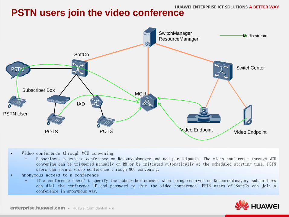
PSTN users join the video conference
SwitchManager
ResourceManager
SoftCo
SwitchCenter
MCU
Video EndpointPOTS Video Endpoint
PSTN User
POTS
Media stream
Subscriber Box
IAD
• Video conference through MCU convening• Subscribers reserve a conference on ResourceManager and add participants. The video conference through MCU
convening can be triggered manually on RM or be initiated automatically at the scheduled starting time. PSTNusers can join a video conference through MCU convening.
• Anonymous access to a conference• If a conference doesn’t specify the subscriber numbers when being reserved on ResourceManager, subscribers
can dial the conference ID and password to join the video conference. PSTN users of SoftCo can join aconference in anonymous way.
7
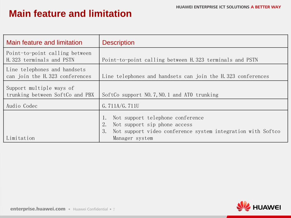
Main feature and limitation
Main feature and limitation Description
Point-to-point calling betweenH.323 terminals and PSTN Point-to-point calling between H.323 terminals and PSTN
Line telephones and handsets can join the H.323 conferences Line telephones and handsets can join the H.323 conferences
Support multiple ways of trunking between SoftCo and PBX SoftCo support NO.7,NO.1 and AT0 trunking
Audio Codec G.711A/G.711U
Limitation
1. Not support telephone conference2. Not support sip phone access3. Not support video conference system integration with Softco
Manager system
8
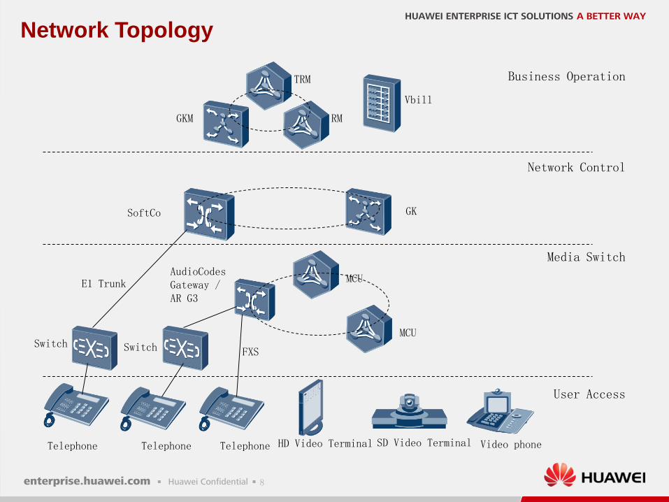
Network Topology
Switch
MCU
SD Video Terminal
GKM RM
Telephone
SoftCo GK
AudioCodes Gateway /AR G3
Video phone
Vbill
TRM
Switch
MCU
Telephone HD Video Terminal
Business Operation
Network Control
Media Switch
User Access
E1 Trunk
Telephone
FXS
9
Content
Introduction of AudioCodes MediaPack Series
Networking Architecture
Introduction of SoftCo
Introduction of AR G3 Series Router
1
2
3
4
Configuration Guide5
10
Introduction of SoftCo
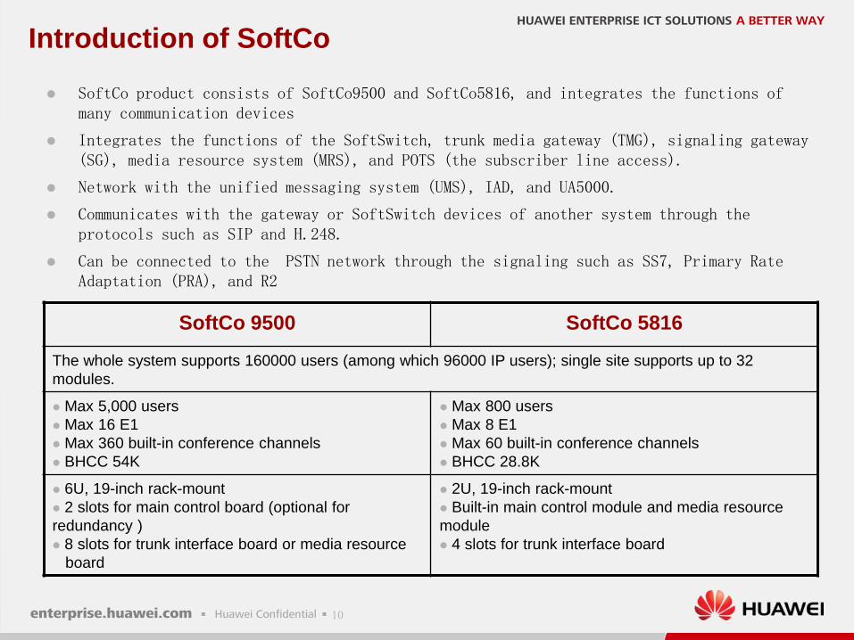
SoftCo product consists of SoftCo9500 and SoftCo5816, and integrates the functions of many communication devices
Integrates the functions of the SoftSwitch, trunk media gateway (TMG), signaling gateway (SG), media resource system (MRS), and POTS (the subscriber line access).
Network with the unified messaging system (UMS), IAD, and UA5000.
Communicates with the gateway or SoftSwitch devices of another system through the protocols such as SIP and H.248.
Can be connected to the PSTN network through the signaling such as SS7, Primary Rate Adaptation (PRA), and R2
SoftCo 9500 SoftCo 5816
The whole system supports 160000 users (among which 96000 IP users); single site supports up to 32
modules.
Max 5,000 users
Max 16 E1
Max 360 built-in conference channels
BHCC 54K
Max 800 users
Max 8 E1
Max 60 built-in conference channels
BHCC 28.8K
6U, 19-inch rack-mount
2 slots for main control board (optional for
redundancy )
8 slots for trunk interface board or media resource
board
2U, 19-inch rack-mount
Built-in main control module and media resource
module
4 slots for trunk interface board
11
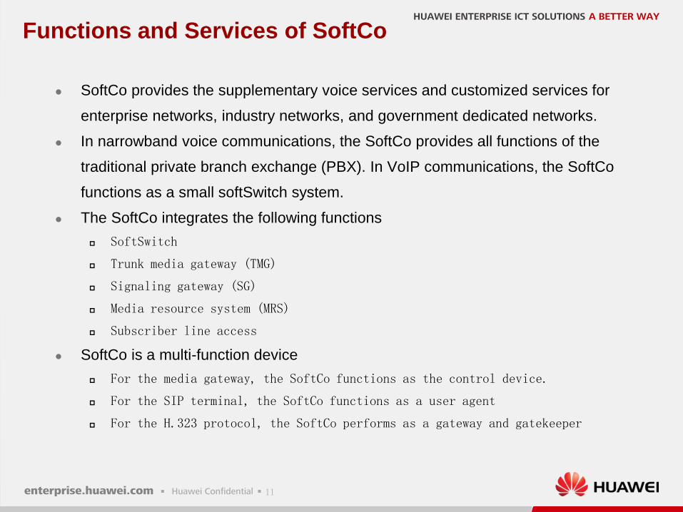
Functions and Services of SoftCo
SoftCo provides the supplementary voice services and customized services for
enterprise networks, industry networks, and government dedicated networks.
In narrowband voice communications, the SoftCo provides all functions of the
traditional private branch exchange (PBX). In VoIP communications, the SoftCo
functions as a small softSwitch system.
The SoftCo integrates the following functions
SoftSwitch
Trunk media gateway (TMG)
Signaling gateway (SG)
Media resource system (MRS)
Subscriber line access
SoftCo is a multi-function device
For the media gateway, the SoftCo functions as the control device.
For the SIP terminal, the SoftCo functions as a user agent
For the H.323 protocol, the SoftCo performs as a gateway and gatekeeper
12
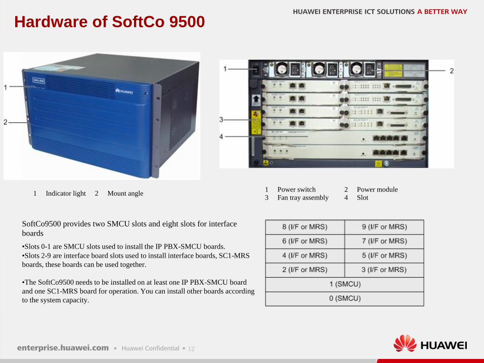
Hardware of SoftCo 9500
1 Indicator light 2 Mount angle1 Power switch 2 Power module
3 Fan tray assembly 4 Slot
SoftCo9500 provides two SMCU slots and eight slots for interface
boards
•Slots 0-1 are SMCU slots used to install the IP PBX-SMCU boards.
•Slots 2-9 are interface board slots used to install interface boards, SC1-MRS
boards, these boards can be used together.
•The SoftCo9500 needs to be installed on at least one IP PBX-SMCU board
and one SC1-MRS board for operation. You can install other boards according
to the system capacity.
13
Board of SoftCo 9500
SC1-MCU: main control board of SoftCo, provides two 100Base-TX service network interfaces
and two debugging interfaces
SC1-SMCU: main control board of the SoftCo, provides three 100Base-TX service network
interfaces and two debugging interfaces
SC1-MRU-128: media resource board, provides two debugging interfaces
SC1-MRS: media resource system board of the SoftCo9500 and provides two debugging ports
SC1-DTU-4: digital trunk interface board, provides four E1 interfaces and a debugging
interface
SC1-DTU-8: digital trunk interface board, provides eight E1 interfaces and a debugging
interface
SC1-ATU-8 (analog trunk unit-8): mainly provides access to analog trunk. It can connect
eight POTS ports at the local exchange
SC1-EXU-4: an extension board for POTS users, provides four user extension port (UEP)
interfaces
SC1-ASU: analog subscriber interface board, which provides 40 foreign exchange subscriber
(FXS) interfaces
14
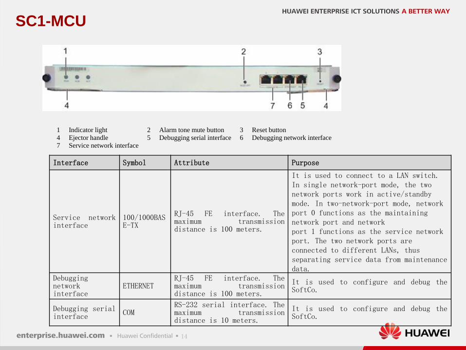
SC1-MCU
1 Indicator light 2 Alarm tone mute button 3 Reset button
4 Ejector handle 5 Debugging serial interface 6 Debugging network interface
7 Service network interface
Interface Symbol Attribute Purpose
Service networkinterface
100/1000BASE-TX
RJ-45 FE interface. Themaximum transmissiondistance is 100 meters.
It is used to connect to a LAN switch. In single network-port mode, the twonetwork ports work in active/standby mode. In two-network-port mode, network port 0 functions as the maintainingnetwork port and networkport 1 functions as the service network port. The two network ports areconnected to different LANs, thus separating service data from maintenance data.
Debuggingnetworkinterface
ETHERNETRJ-45 FE interface. Themaximum transmissiondistance is 100 meters.
It is used to configure and debug theSoftCo.
Debugging serialinterface COM
RS-232 serial interface. Themaximum transmissiondistance is 10 meters.
It is used to configure and debug theSoftCo.
15
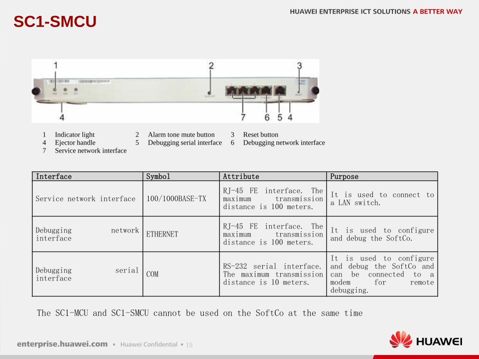
SC1-SMCU
1 Indicator light 2 Alarm tone mute button 3 Reset button
4 Ejector handle 5 Debugging serial interface 6 Debugging network interface
7 Service network interface
Interface Symbol Attribute Purpose
Service network interface 100/1000BASE-TXRJ-45 FE interface. Themaximum transmissiondistance is 100 meters.
It is used to connect toa LAN switch.
Debugging networkinterface ETHERNET
RJ-45 FE interface. Themaximum transmissiondistance is 100 meters.
It is used to configureand debug the SoftCo.
Debugging serialinterface COM
RS-232 serial interface.The maximum transmissiondistance is 10 meters.
It is used to configureand debug the SoftCo andcan be connected to amodem for remotedebugging.
The SC1-MCU and SC1-SMCU cannot be used on the SoftCo at the same time
16
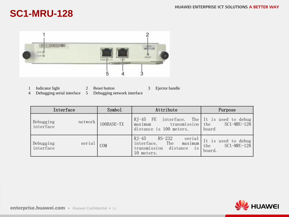
SC1-MRU-128
1 Indicator light 2 Reset button 3 Ejector handle
4 Debugging serial interface 5 Debugging network interface
Interface Symbol Attribute Purpose
Debugging networkinterface 100BASE-TX
RJ-45 FE interface. Themaximum transmissiondistance is 100 meters.
It is used to debugthe SC1-MRU-128board
Debugging serialinterface COM
RJ-45 RS-232 serialinterface. The maximumtransmission distance is10 meters.
It is used to debugthe SC1-MRU-128board.
17
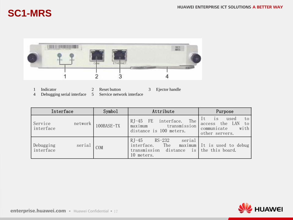
SC1-MRS
1 Indicator 2 Reset button 3 Ejector handle
4 Debugging serial interface 5 Service network interface
Interface Symbol Attribute Purpose
Service networkinterface 100BASE-TX
RJ-45 FE interface. Themaximum transmissiondistance is 100 meters.
It is used toaccess the LAN tocommunicate withother servers.
Debugging serialinterface COM
RJ-45 RS-232 serialinterface. The maximumtransmission distance is10 meters.
It is used to debugthe this board.
18
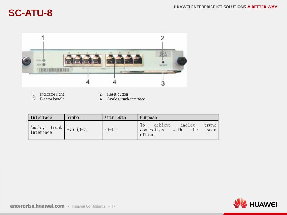
SC-ATU-8
1 Indicator light 2 Reset button
3 Ejector handle 4 Analog trunk interface
Interface Symbol Attribute Purpose
Analog trunkinterface FXO (0-7) RJ-11
To achieve analog trunkconnection with the peeroffice.
19
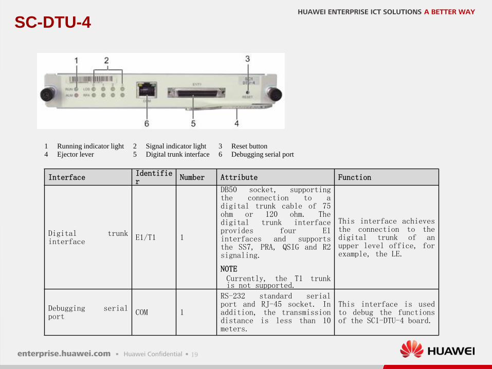
SC-DTU-4
1 Running indicator light 2 Signal indicator light 3 Reset button
4 Ejector lever 5 Digital trunk interface 6 Debugging serial port
Interface Identifier Number Attribute Function
Digital trunkinterface
E1/T1 1
DB50 socket, supportingthe connection to adigital trunk cable of 75ohm or 120 ohm. Thedigital trunk interfaceprovides four E1interfaces and supportsthe SS7, PRA, QSIG and R2signaling.
NOTECurrently, the T1 trunkis not supported.
This interface achievesthe connection to thedigital trunk of anupper level office, forexample, the LE.
Debugging serialport COM 1
RS-232 standard serialport and RJ-45 socket. Inaddition, the transmissiondistance is less than 10meters.
This interface is usedto debug the functionsof the SC1-DTU-4 board.
20
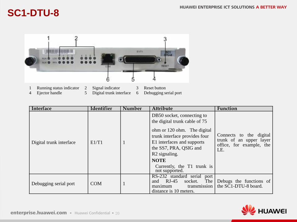
SC1-DTU-8
1 Running status indicator 2 Signal indicator 3 Reset button
4 Ejector handle 5 Digital trunk interface 6 Debugging serial port
Interface Identifier Number Attribute Function
Digital trunk interface E1/T1 1
DB50 socket, connecting to
the digital trunk cable of 75
ohm or 120 ohm. The digital
trunk interface provides four
E1 interfaces and supports
the SS7, PRA, QSIG and
R2 signaling.
NOTE
Currently, the T1 trunk isnot supported.
Connects to the digitaltrunk of an upper layeroffice, for example, theLE.
Debugging serial port COM 1
RS-232 standard serial portand RJ-45 socket. Themaximum transmissiondistance is 10 meters.
Debugs the functions ofthe SC1-DTU-8 board.
21
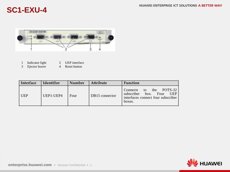
SC1-EXU-4
1 Indicator light 2 UEP interface
3 Ejector leaver 4 Reset button
Interface Identifier Number Attribute Function
UEP UEP1-UEP4 Four DB15 connector
Connects to the POTS-32subscriber box. Four UEPinterfaces connect four subscriberboxes.
22
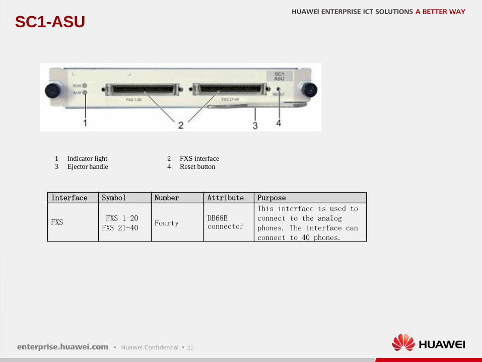
SC1-ASU
1 Indicator light 2 FXS interface
3 Ejector handle 4 Reset button
Interface Symbol Number Attribute Purpose
FXS FXS 1-20FXS 21-40
FourtyDB68Bconnector
This interface is used toconnect to the analogphones. The interface canconnect to 40 phones.

23
SoftCo9500 power distribution system
SoftCo9500 uses the 100-240 V AC power distribution system. The power
distribution system is at the top of the shelf. It comprises a power
distribution frame (PDF) and power modules
one power switch, three power module slots, and one alarm tone mute
button on the PDF
SoftCo9500 uses two power supply modules that can be swapped and work in
active/standby mode. The AC and DC power supplies are supported
1 Power switch 2 Power module 3 Alarm tone mute button
24
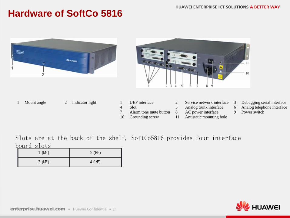
Hardware of SoftCo 5816
1 Mount angle 2 Indicator light 1 UEP interface 2 Service network interface 3 Debugging serial interface
4 Slot 5 Analog trunk interface 6 Analog telephone interface
7 Alarm tone mute button 8 AC power interface 9 Power switch
10 Grounding screw 11 Antistatic mounting hole
Slots are at the back of the shelf, SoftCo5816 provides four interface board slots
25
Board of SoftCo 5816
SC0-DTU-4 :digital trunk interface board, provides four E1 interfaces
SC0-ATU-8: provides access to analog trunk
26
SC0-DTU-4
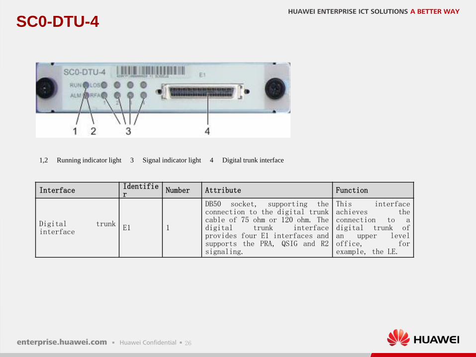
1,2 Running indicator light 3 Signal indicator light 4 Digital trunk interface
Interface Identifier Number Attribute Function
Digital trunkinterface E1 1
DB50 socket, supporting theconnection to the digital trunkcable of 75 ohm or 120 ohm. Thedigital trunk interfaceprovides four E1 interfaces andsupports the PRA, QSIG and R2signaling.
This interfaceachieves theconnection to adigital trunk ofan upper leveloffice, forexample, the LE.
27
SC0-ATU-8
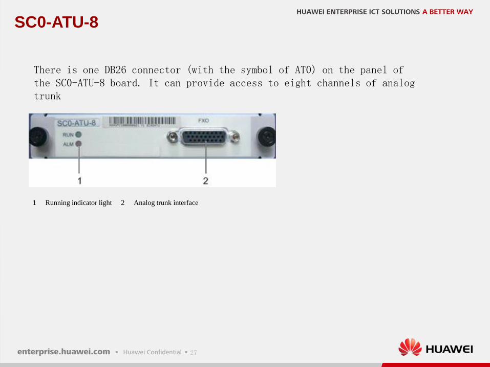
1 Running indicator light 2 Analog trunk interface
There is one DB26 connector (with the symbol of AT0) on the panel of the SC0-ATU-8 board. It can provide access to eight channels of analog trunk

28
Content
Introduction of AudioCodes MediaPack Series
Networking Architecture
Introduction of SoftCo
Introduction of AR G3 Series Router
1
2
3
4
Configuration Guide5
29
Introduction of AudioCodes MediaPack
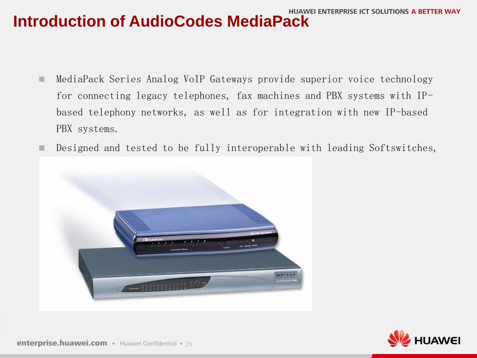
MediaPack Series Analog VoIP Gateways provide superior voice technology
for connecting legacy telephones, fax machines and PBX systems with IP-
based telephony networks, as well as for integration with new IP-based
PBX systems.
Designed and tested to be fully interoperable with leading Softswitches,
SIP servers and H.323 gatekeepers
30
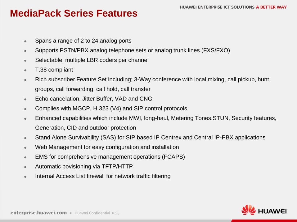
MediaPack Series Features
Spans a range of 2 to 24 analog ports
Supports PSTN/PBX analog telephone sets or analog trunk lines (FXS/FXO)
Selectable, multiple LBR coders per channel
T.38 compliant
Rich subscriber Feature Set including; 3-Way conference with local mixing, call pickup, hunt
groups, call forwarding, call hold, call transfer
Echo cancelation, Jitter Buffer, VAD and CNG
Complies with MGCP, H.323 (V4) and SIP control protocols
Enhanced capabilities which include MWI, long-haul, Metering Tones,STUN, Security features,
Generation, CID and outdoor protection
Stand Alone Survivability (SAS) for SIP based IP Centrex and Central IP-PBX applications
Web Management for easy configuration and installation
EMS for comprehensive management operations (FCAPS)
Automatic povisioning via TFTP/HTTP
Internal Access List firewall for network traffic filtering
31
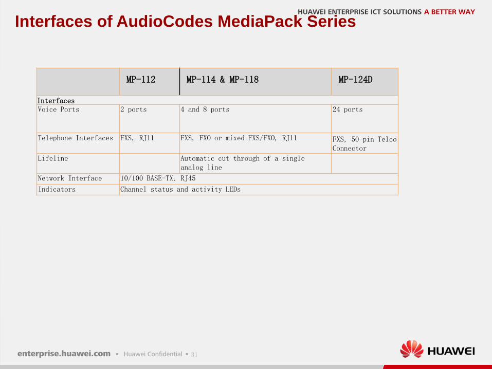
Interfaces of AudioCodes MediaPack Series
MP-112 MP-114 & MP-118 MP-124D
InterfacesVoice Ports 2 ports 4 and 8 ports 24 ports
Telephone Interfaces FXS, RJ11 FXS, FXO or mixed FXS/FXO, RJ11 FXS, 50-pin Telco Connector
Lifeline Automatic cut through of a single analog line
Network Interface 10/100 BASE-TX, RJ45
Indicators Channel status and activity LEDs
32
Content
Introduction of AudioCodes MediaPack Series
Networking Architecture
Introduction of SoftCo
Introduction of AR G3 Series Router
1
2
3
4
Configuration Guide5
33
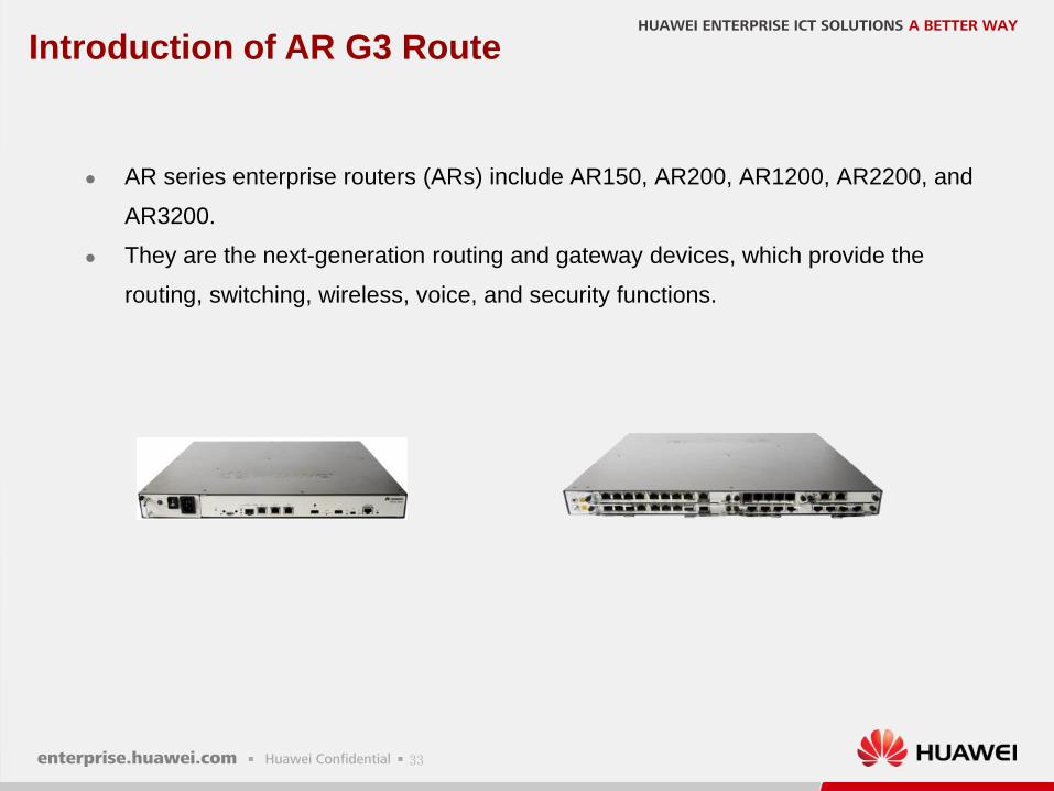
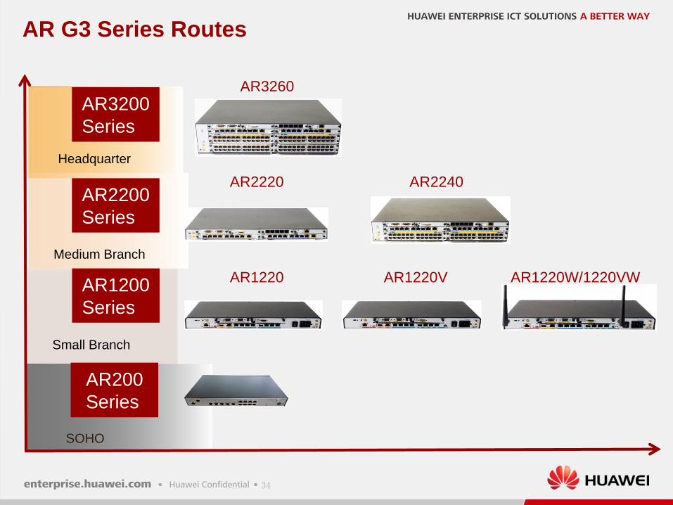
Introduction of AR G3 Route
AR series enterprise routers (ARs) include AR150, AR200, AR1200, AR2200, and
AR3200.
They are the next-generation routing and gateway devices, which provide the
routing, switching, wireless, voice, and security functions.
34
AR G3 Series Routes
SOHO
AR2220
AR3200
Series
AR2200
Series
AR1200
Series
Small Branch
AR2240
AR3260
AR1220 AR1220V
Medium Branch
Headquarter
AR1220W/1220VW
AR200
Series
35
Voice Connection feature of AR G3 Router
Among the AR200 series routers, only the AR207Vs support the voice
features.
Among the AR1200 series routers, only the AR1220Vs and
AR1220VWs support the voice features.
The AR2200 and AR3200 series support the voice features only after
the DSP module is installed.
To provide voice services for POTS users on AR1200, AR2200 ,and
AR3200 series routers, 4FXS/1FXO board is required.
36
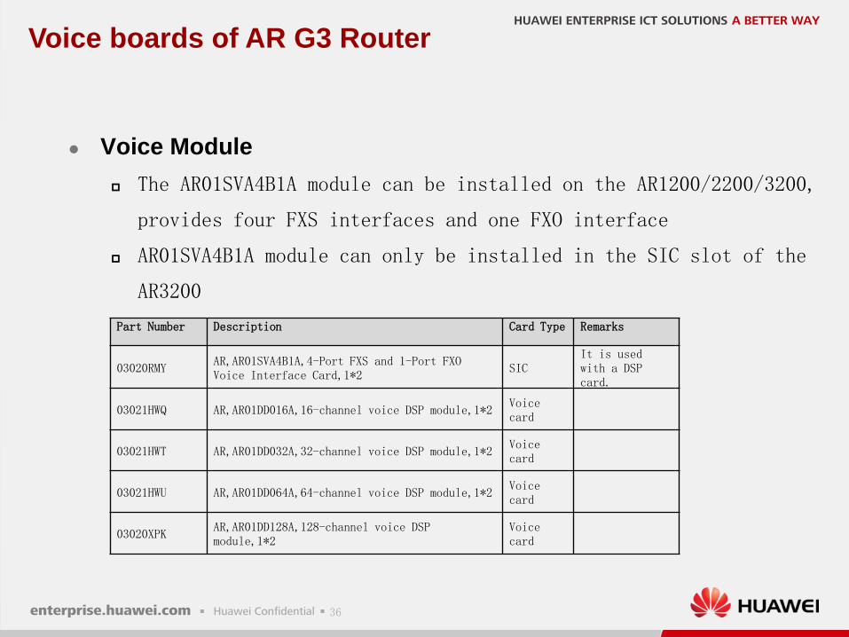
Voice boards of AR G3 Router
Voice Module
The AR01SVA4B1A module can be installed on the AR1200/2200/3200,
provides four FXS interfaces and one FXO interface
AR01SVA4B1A module can only be installed in the SIC slot of the
AR3200
Part Number Description Card Type Remarks
03020RMYAR,AR01SVA4B1A,4-Port FXS and 1-Port FXO Voice Interface Card,1*2
SICIt is used with a DSP card.
03021HWQ AR,AR01DD016A,16-channel voice DSP module,1*2Voice card
03021HWT AR,AR01DD032A,32-channel voice DSP module,1*2Voice card
03021HWU AR,AR01DD064A,64-channel voice DSP module,1*2Voice card
03020XPKAR,AR01DD128A,128-channel voice DSP module,1*2
Voice card
37
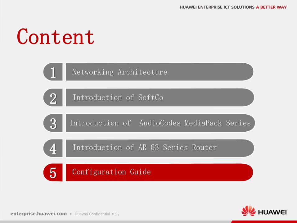
Content
Introduction of AudioCodes MediaPack Series
Networking Architecture
Introduction of SoftCo
Introduction of AR G3 Series Router
1
2
3
4
Configuration Guide5
38
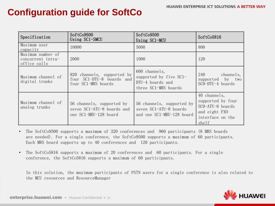
Configuration guide for SoftCo
Specification SoftCo9500Using SC1-SMCU
SoftCo9500Using SC1-MCU
SoftCo5816
Maximum user capacity 10000 5000 800
Maximum number of concurrent intra-office calls
2000 1000 120
Maximum channel of digital trunks
920 channels, supported byfour SC1-DTU-8 boards andfour SC1-MRS boards
600 channels,supported by five SC1-DTU-4 boards andthree SC1-MRS boards
240 channels,supported by twoSC0-DTU-4 boards
Maximum channel of analog trunks
56 channels, supported by seven SC1-ATU-8 boards and one SC1-MRU-128 board
56 channels, supported by seven SC1-ATU-8 boards and one SC1-MRU-128 board
40 channels, supported by four SC0-ATU-8 boards and eight FXOinterface on the shelf
• The SoftCo9500 supports a maximum of 320 conferences and 960 participants (8 MRS boards are needed). For a single conference, the SoftCo9500 supports a maximum of 60 participants. Each MRS board supports up to 40 conferences and 120 participants.
• The SoftCo5816 supports a maximum of 20 conferences and 60 participants. For a single conference, the SoftCo5816 supports a maximum of 60 participants.
In this solution, the maximum participants of PSTN users for a single conference is also related to the MCU resources and ResourceManager
39
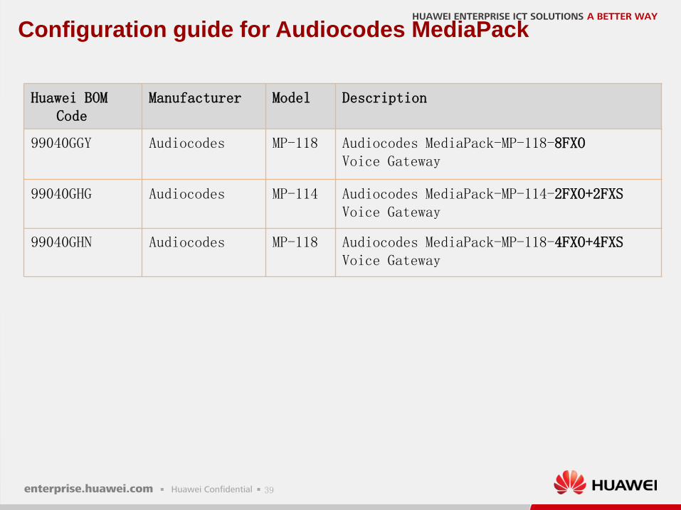
Configuration guide for Audiocodes MediaPack
Huawei BOM Code
Manufacturer Model Description
99040GGY Audiocodes MP-118 Audiocodes MediaPack-MP-118-8FXOVoice Gateway
99040GHG Audiocodes MP-114 Audiocodes MediaPack-MP-114-2FXO+2FXSVoice Gateway
99040GHN Audiocodes MP-118 Audiocodes MediaPack-MP-118-4FXO+4FXSVoice Gateway
40
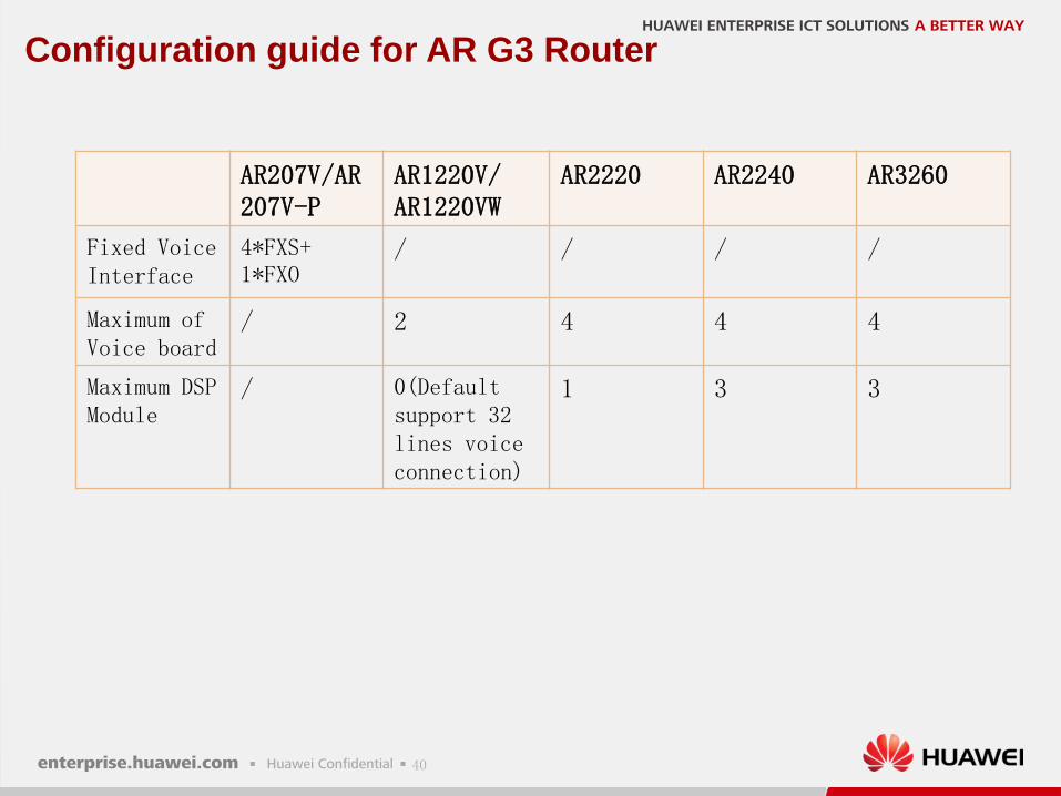
Configuration guide for AR G3 Router
AR207V/AR207V-P
AR1220V/AR1220VW
AR2220 AR2240 AR3260
Fixed Voice Interface
4*FXS+ 1*FXO
/ / / /
Maximum of Voice board
/ 2 4 4 4
Maximum DSP Module
/ 0(Defaultsupport 32 lines voice connection)
1 3 3

Copyright©2012 Huawei Technologies Co., Ltd. All Rights Reserved.The information in this document may contain predictive statements including, without limitation, statements regarding the future financial and
operating results, future product portfolio, new technology, etc. There are a number of factors that could cause actual results and developments to
differ materially from those expressed or implied in the predictive statements. Therefore, such information is provided for reference purpose only and
constitutes neither an offer nor an acceptance. Huawei may change the information at any time without notice.
HUAWEI ENTERPRISE ICT SOLUTIONS A BETTER WAY