version #1.8 metal roof assembly manual
TRANSCRIPT
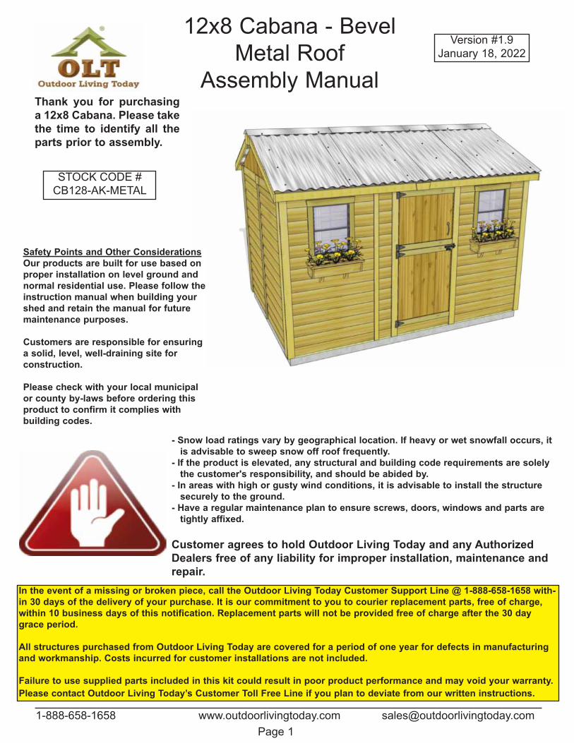
12x8 Cabana - Bevel
Metal Roof
Assembly Manual
Version #1.9
January 18, 2022
1-888-658-1658 www.outdoorlivingtoday.com [email protected]
Page 1
Thank you for purchasing
a 12x8 Cabana. Please take
the time to identify all the
parts prior to assembly.
In the event of a missing or broken piece, call the Outdoor Living Today Customer Support Line @ 1-888-658-1658 with-
in 30 days of the delivery of your purchase. It is our commitment to you to courier replacement parts, free of charge,
within 10 business days of this notification. Replacement parts will not be provided free of charge after the 30 day
grace period.
All structures purchased from Outdoor Living Today are covered for a period of one year for defects in manufacturing
and workmanship. Costs incurred for customer installations are not included.
Failure to use supplied parts included in this kit could result in poor product performance and may void your warranty.
Please contact Outdoor Living Today’s Customer Toll Free Line if you plan to deviate from our written instructions.
Safety Points and Other Considerations
Our products are built for use based on
proper installation on level ground and
normal residential use. Please follow the
instruction manual when building your
shed and retain the manual for future
maintenance purposes.
Customers are responsible for ensuring
a solid, level, well-draining site for
construction.
Please check with your local municipal
or county by-laws before ordering this
product to confirm it complies with
building codes.
- Snow load ratings vary by geographical location. If heavy or wet snowfall occurs, it
is advisable to sweep snow off roof frequently.
- If the product is elevated, any structural and building code requirements are solely
the customer's responsibility, and should be abided by.
- In areas with high or gusty wind conditions, it is advisable to install the structure
securely to the ground.
- Have a regular maintenance plan to ensure screws, doors, windows and parts are
tightly affixed.
Customer agrees to hold Outdoor Living Today and any Authorized
Dealers free of any liability for improper installation, maintenance and
repair.
STOCK CODE #
CB128-AK-METAL
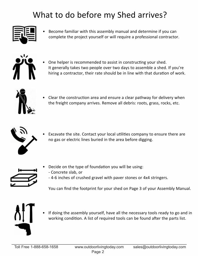
What to do before my Shed arrives?Become familiar with this assembly manual and determine if you can •complete the project yourself or will require a professional contractor.
Clear the construction area and ensure a clear pathway for delivery when •the freight company arrives. Remove all debris: roots, grass, rocks, etc.
Excavate the site. Contact your local utilities company to ensure there are •no gas or electric lines buried in the area before digging.
Decide on the type of foundation you will be using: • Concrete slab, or 46 inches of crushed gravel with paver stones or 4x4 stringers. You can find the footprint for your shed on Page 3 of your Assembly Manual.
If doing the assembly yourself, have all the necessary tools ready to go and in •working condition. A list of required tools can be found after the parts list.
One helper is recommended to assist in constructing your shed. •It generally takes two people over two days to assemble a shed. If you’re hiring a contractor, their rate should be in line with that duration of work.
Toll Free 1-888-658-1658 www.outdoorlivingtoday.com [email protected]
Page 2
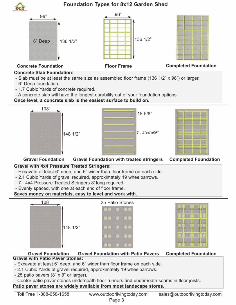
Foundation Types for 8x12 Garden Shed
Concrete Slab Foundation:
- Slab must be at least the same size as assembled floor frame (136 1/2” x 96”) or larger.
- 6” Deep foundation.
- 1.7 Cubic Yards of concrete required.
- A concrete slab will have the longest durability out of your foundation options.
Once level, a concrete slab is the easiest surface to build on.
Gravel with 4x4 Pressure Treated Stringers:
- Excavate at least 6” deep, and 6” wider than floor frame on each side.
- 2.1 Cubic Yards of gravel required, approximately 19 wheelbarrows.
- 7 - 4x4 Pressure Treated Stringers 8’ long required.
- Evenly spaced, with one at each end of floor frame.
Saves money on materials, easy to level and work with.
Gravel with Patio Paver Stones:
- Excavate at least 6” deep, and 6” wider than floor frame on each side.
- 2.1 Cubic Yards of gravel required, approximately 19 wheelbarrows.
- 25 patio pavers (8” x 8” or larger).
- Center patio paver stones underneath floor runners and underneath seams in floor joists.
Patio paver stones are widely available from most landscape stores.
96”
136 1/2”6” Deep
108”
148 1/2” 7 - 4”x4”x96”
25 Patio Stones
Floor FrameConcrete Foundation Completed Foundation
18 5/8”
Gravel Foundation Gravel Foundation with treated stringers Completed Foundation
Gravel Foundation Gravel Foundation with Patio Pavers Completed Foundation
96”
136 1/2”
108”
148 1/2”
Toll Free 1-888-658-1658 www.outdoorlivingtoday.com [email protected]
Page 3
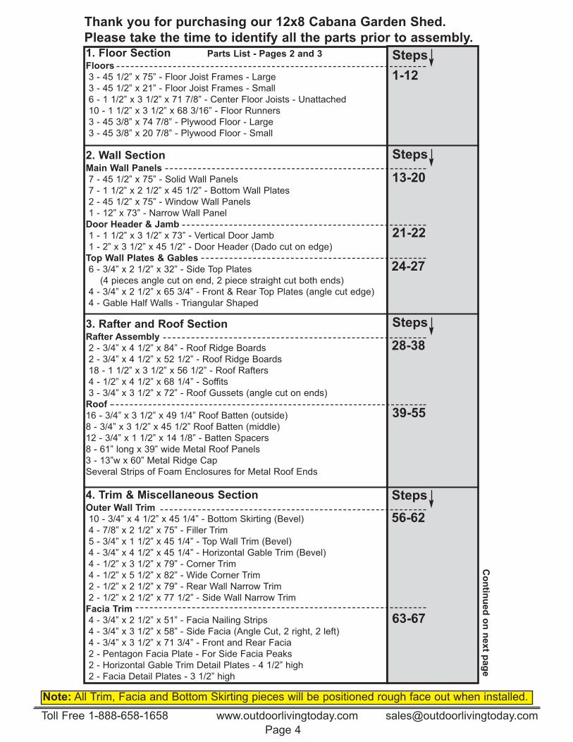
Thank you for purchasing our 12x8 Cabana Garden Shed.
Please take the time to identify all the parts prior to assembly.
Note: All Trim, Facia and Bottom Skirting pieces will be positioned rough face out when installed.
1. Floor Section Floors
3 - 45 1/2” x 75” - Floor Joist Frames - Large
3 - 45 1/2” x 21” - Floor Joist Frames - Small
6 - 1 1/2” x 3 1/2” x 71 7/8” - Center Floor Joists - Unattached
10 - 1 1/2” x 3 1/2” x 68 3/16” - Floor Runners
3 - 45 3/8” x 74 7/8” - Plywood Floor - Large
3 - 45 3/8” x 20 7/8” - Plywood Floor - Small
2. Wall Section
Main Wall Panels
7 - 45 1/2” x 75” - Solid Wall Panels
7 - 1 1/2” x 2 1/2” x 45 1/2” - Bottom Wall Plates
2 - 45 1/2” x 75” - Window Wall Panels
1 - 12” x 73” - Narrow Wall Panel
Door Header & Jamb
1 - 1 1/2” x 3 1/2” x 73” - Vertical Door Jamb
1 - 2” x 3 1/2” x 45 1/2” - Door Header (Dado cut on edge)
Top Wall Plates & Gables
6 - 3/4” x 2 1/2” x 32” - Side Top Plates
(4 pieces angle cut on end, 2 piece straight cut both ends)
4 - 3/4” x 2 1/2” x 65 3/4” - Front & Rear Top Plates (angle cut edge)
4 - Gable Half Walls - Triangular Shaped
3. Rafter and Roof Section Rafter Assembly
2 - 3/4” x 4 1/2” x 84” - Roof Ridge Boards
2 - 3/4” x 4 1/2” x 52 1/2” - Roof Ridge Boards
18 - 1 1/2” x 3 1/2” x 56 1/2” - Roof Rafters
4 - 1/2” x 4 1/2” x 68 1/4” - Soffits
3 - 3/4” x 3 1/2” x 72” - Roof Gussets (angle cut on ends)
Roof
16 - 3/4” x 3 1/2” x 49 1/4” Roof Batten (outside)
8 - 3/4” x 3 1/2” x 45 1/2” Roof Batten (middle)
12 - 3/4” x 1 1/2” x 14 1/8” - Batten Spacers
8 - 61” long x 39” wide Metal Roof Panels
3 - 13”w x 60” Metal Ridge Cap
Several Strips of Foam Enclosures for Metal Roof Ends
4. Trim & Miscellaneous Section
Outer Wall Trim
10 - 3/4” x 4 1/2” x 45 1/4” - Bottom Skirting (Bevel)
4 - 7/8” x 2 1/2” x 75” - Filler Trim
5 - 3/4” x 1 1/2” x 45 1/4” - Top Wall Trim (Bevel)
4 - 3/4” x 4 1/2” x 45 1/4” - Horizontal Gable Trim (Bevel)
4 - 1/2” x 3 1/2” x 79” - Corner Trim
4 - 1/2” x 5 1/2” x 82” - Wide Corner Trim
2 - 1/2” x 2 1/2” x 79” - Rear Wall Narrow Trim
2 - 1/2” x 2 1/2” x 77 1/2” - Side Wall Narrow Trim
Facia Trim
4 - 3/4” x 2 1/2” x 51” - Facia Nailing Strips
4 - 3/4” x 3 1/2” x 58” - Side Facia (Angle Cut, 2 right, 2 left)
4 - 3/4” x 3 1/2” x 71 3/4” - Front and Rear Facia
2 - Pentagon Facia Plate - For Side Facia Peaks
2 - Horizontal Gable Trim Detail Plates - 4 1/2” high
2 - Facia Detail Plates - 3 1/2” high
21-22
Steps
Steps
24-27
Steps
39-55
56-62
63-67
Steps
13-20
1-12
28-38
Parts List - Pages 2 and 3
Co
ntin
ued
on
next p
ag
e
Toll Free 1-888-658-1658 www.outdoorlivingtoday.com [email protected]
Page 4
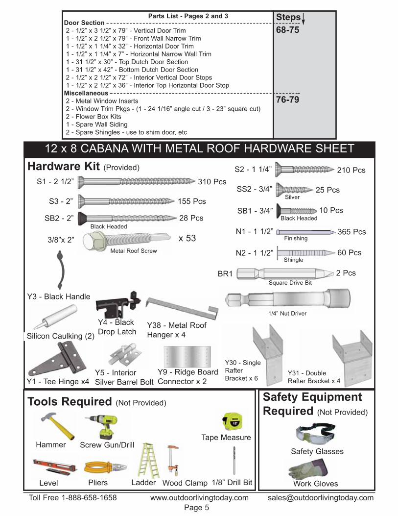
12 x 8 CABANA WITH METAL ROOF HARDWARE SHEET
S1 - 2 1/2”
S3 - 2”
S2 - 1 1/4”
SS2 - 3/4”
SB2 - 2”
N1 - 1 1/2”
N2 - 1 1/2”
Y1 - Tee Hinge x4
Silver
Finishing
Shingle
Square Drive Bit
Hardware Kit (Provided)
Safety Glasses
Work Gloves
Safety Equipment
Required (Not Provided)
Screw Gun/DrillTape Measure
Hammer
Wood ClampLevel Pliers
Tools Required (Not Provided)
1/8” Drill Bit
Y4 - Black
Drop Latch
Y5 - Interior
Silver Barrel Bolt
310 Pcs
155 Pcs
28 Pcs
210 Pcs
60 Pcs
2 Pcs
365 Pcs
10 Pcs
25 Pcs
Black Headed
Black Headed
Y30 - Single
Rafter
Bracket x 6Y31 - Double
Rafter Bracket x 4
Door Section
2 - 1/2” x 3 1/2” x 79” - Vertical Door Trim
1 - 1/2” x 2 1/2” x 79” - Front Wall Narrow Trim
1 - 1/2” x 1 1/4” x 32” - Horizontal Door Trim
1 - 1/2” x 1 1/4” x 7” - Horizontal Narrow Wall Trim
1 - 31 1/2” x 30” - Top Dutch Door Section
1 - 31 1/2” x 42” - Bottom Dutch Door Section
2 - 1/2” x 2 1/2” x 72” - Interior Vertical Door Stops
1 - 1/2” x 2 1/2” x 36” - Interior Top Horizontal Door Stop
Miscellaneous
2 - Metal Window Inserts
2 - Window Trim Pkgs - (1 - 24 1/16” angle cut / 3 - 23” square cut)
2 - Flower Box Kits
1 - Spare Wall Siding
2 - Spare Shingles - use to shim door, etc
Steps
76-79
68-75
Parts List - Pages 2 and 3
Ladder
SB1 - 3/4”
BR1
Y3 - Black Handle
Y9 - Ridge Board
Connector x 2
x 533/8”x 2”
Metal Roof Screw
1/4” Nut Driver
Silicon Caulking (2)
Y38 - Metal Roof
Hanger x 4
Toll Free 1-888-658-1658 www.outdoorlivingtoday.com [email protected]
Page 5
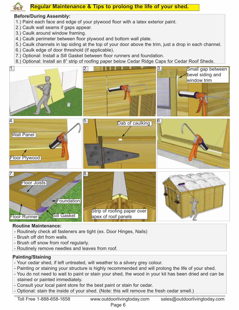
Regular Maintenance & Tips to prolong the life of your shed.
Before/During Assembly:
1.) Paint each face and edge of your plywood floor with a latex exterior paint.
2.) Caulk wall seams if gaps appear.
3.) Caulk around window framing.
4.) Caulk perimeter between floor plywood and bottom wall plate.
5.) Caulk channels in lap siding at the top of your door above the trim, just a drop in each channel.
6.) Caulk edge of door threshold (if applicable).
7.) Optional: Install a Sill Gasket between floor runners and foundation.
8.) Optional: Install an 8” strip of roofing paper below Cedar Ridge Caps for Cedar Roof Sheds.
Routine Maintenance:
- Routinely check all fasteners are tight (ex. Door Hinges, Nails)
- Brush off dirt from walls.
- Brush off snow from roof regularly.
- Routinely remove needles and leaves from roof.
Painting/Staining
- Your cedar shed, if left untreated, will weather to a silvery grey colour.
- Painting or staining your structure is highly recommended and will prolong the life of your shed.
- You do not need to wait to paint or stain your shed, the wood in your kit has been dried and can be
—stained or painted immediately.
- Consult your local paint store for the best paint or stain for cedar.
- Optional: stain the inside of your shed. (Note: this will remove the fresh cedar smell.)
1. 2. 3.
4. 5. 6.
7.
Sill Gasket
Floor Joists
Floor Runner
Foundation
8.
Floor Plywood
Wall Panel
Small gap between
bevel siding and
window trim
Dab of caulking
Strip of roofing paper over
apex of roof panels
Toll Free 1-888-658-1658 www.outdoorlivingtoday.com [email protected]
Page 6
You can find the
Square Drive Bit for
the screws in with
the Hardware Kit Bag.
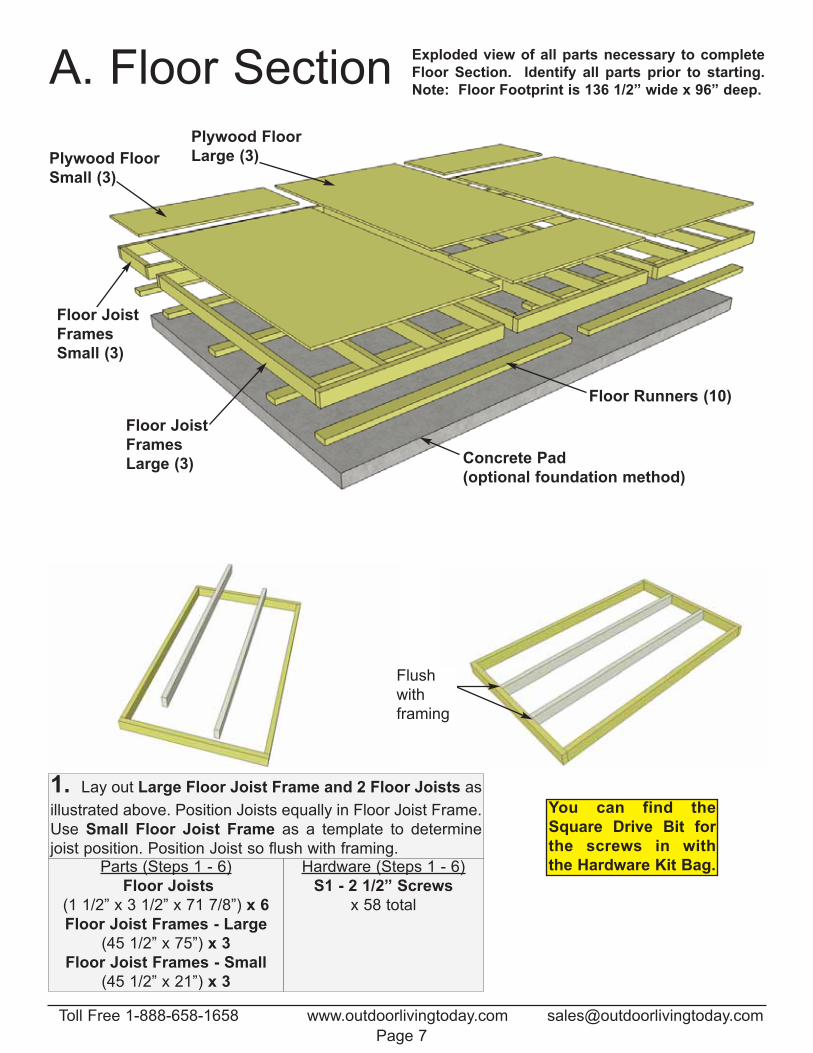
1. Lay out Large Floor Joist Frame and 2 Floor Joists as
illustrated above. Position Joists equally in Floor Joist Frame.
Use Small Floor Joist Frame as a template to determine
joist position. Position Joist so flush with framing.Parts (Steps 1 - 6)
Floor Joists
(1 1/2” x 3 1/2” x 71 7/8”) x 6
Floor Joist Frames - Large
(45 1/2” x 75”) x 3
Floor Joist Frames - Small
(45 1/2” x 21”) x 3
Hardware (Steps 1 - 6)
S1 - 2 1/2” Screws
x 58 total
A. Floor Section
Plywood Floor
Large (3)
Floor Joist
Frames
Large (3)
Floor Runners (10)
Plywood Floor
Small (3)
Concrete Pad
(optional foundation method)
Floor Joist
Frames
Small (3)
Exploded view of all parts necessary to complete
Floor Section. Identify all parts prior to starting.
Note: Floor Footprint is 136 1/2” wide x 96” deep.
Flush
with
framing
Toll Free 1-888-658-1658 www.outdoorlivingtoday.com [email protected]
Page 7
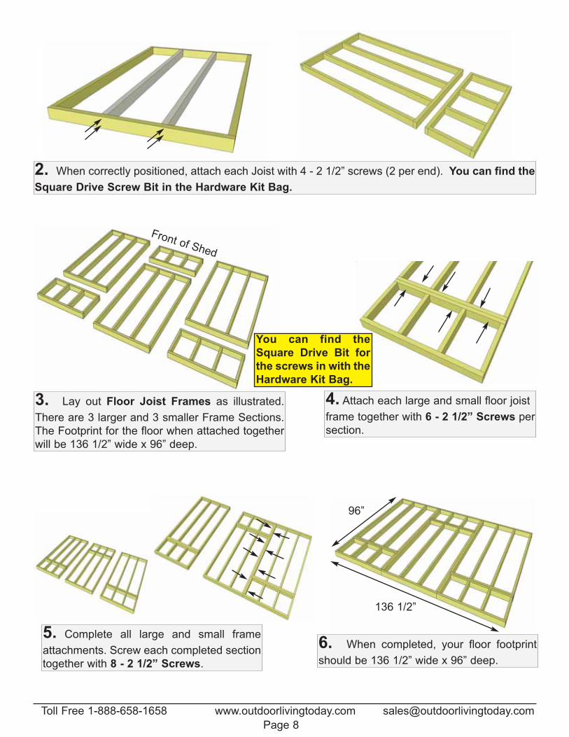
2. When correctly positioned, attach each Joist with 4 - 2 1/2” screws (2 per end). You can find the
Square Drive Screw Bit in the Hardware Kit Bag.
3. Lay out Floor Joist Frames as illustrated.
There are 3 larger and 3 smaller Frame Sections.
The Footprint for the floor when attached together
will be 136 1/2” wide x 96” deep.
5. Complete all large and small frame
attachments. Screw each completed section
together with 8 - 2 1/2” Screws.
Front of Shed
You can find the
Square Drive Bit for
the screws in with the
Hardware Kit Bag.
4. Attach each large and small floor joist
frame together with 6 - 2 1/2” Screws per
section.
96”
136 1/2”
6. When completed, your floor footprint
should be 136 1/2” wide x 96” deep.
Toll Free 1-888-658-1658 www.outdoorlivingtoday.com [email protected]
Page 8
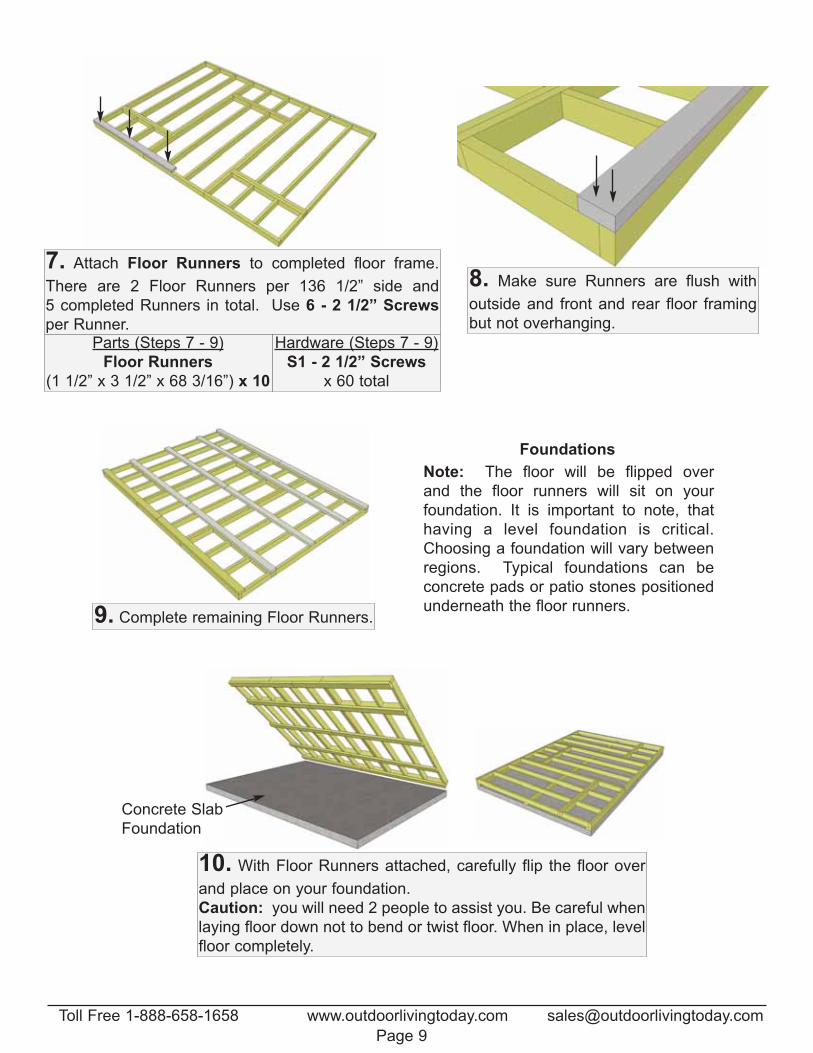
7. Attach Floor Runners to completed floor frame.
There are 2 Floor Runners per 136 1/2” side and
5 completed Runners in total. Use 6 - 2 1/2” Screws
per Runner.Parts (Steps 7 - 9)
Floor Runners
(1 1/2” x 3 1/2” x 68 3/16”) x 10
Hardware (Steps 7 - 9)
S1 - 2 1/2” Screws
x 60 total
8. Make sure Runners are flush with
outside and front and rear floor framing
but not overhanging.
9. Complete remaining Floor Runners.
10. With Floor Runners attached, carefully flip the floor over
and place on your foundation.
Caution: you will need 2 people to assist you. Be careful when
laying floor down not to bend or twist floor. When in place, level
floor completely.
Note: The floor will be flipped over
and the floor runners will sit on your
foundation. It is important to note, that
having a level foundation is critical.
Choosing a foundation will vary between
regions. Typical foundations can be
concrete pads or patio stones positioned
underneath the floor runners.
Foundations
Concrete Slab
Foundation
Toll Free 1-888-658-1658 www.outdoorlivingtoday.com [email protected]
Page 9
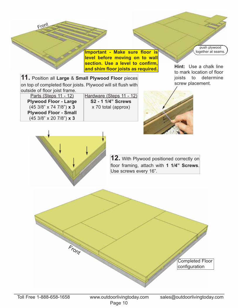
Hint: Use a chalk line
to mark location of floor
joists to determine
screw placement.
Front
11. Position all Large & Small Plywood Floor pieces
on top of completed floor joists. Plywood will sit flush with
outside of floor joist frame. Parts (Steps 11 - 12)
Plywood Floor - Large
(45 3/8” x 74 7/8”) x 3
Plywood Floor - Small
(45 3/8” x 20 7/8”) x 3
Hardware (Steps 11 - 12)
S2 - 1 1/4” Screws
x 70 total (approx)
Important - Make sure floor is
level before moving on to wall
section. Use a level to confirm,
and shim floor joists as required.
12. With Plywood positioned correctly on
floor framing, attach with 1 1/4” Screws.
Use screws every 16”.
push plywood
together at seams.
Front
Completed Floor
configuration
Toll Free 1-888-658-1658 www.outdoorlivingtoday.com [email protected]
Page 10
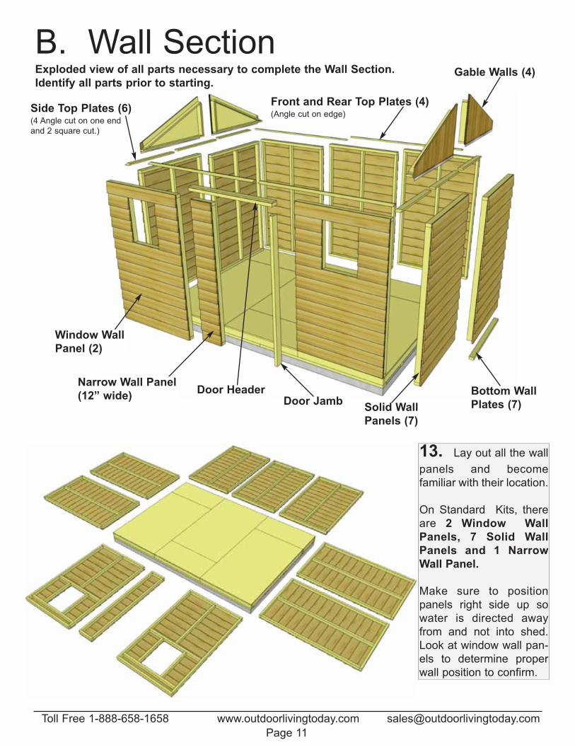
13. Lay out all the wall
panels and become
familiar with their location.
On Standard Kits, there
are 2 Window Wall
Panels, 7 Solid Wall
Panels and 1 Narrow
Wall Panel.
Make sure to position
panels right side up so
water is directed away
from and not into shed.
Look at window wall pan-
els to determine proper
wall position to confirm.
B. Wall SectionExploded view of all parts necessary to complete the Wall Section.
Identify all parts prior to starting.
Window Wall
Panel (2)
Front and Rear Top Plates (4) (Angle cut on edge)
Side Top Plates (6) (4 Angle cut on one end
and 2 square cut.)
Gable Walls (4)
Door Jamb
Narrow Wall Panel
(12” wide)Solid Wall
Panels (7)
Door Header Bottom Wall
Plates (7)
Toll Free 1-888-658-1658 www.outdoorlivingtoday.com [email protected]
Page 11
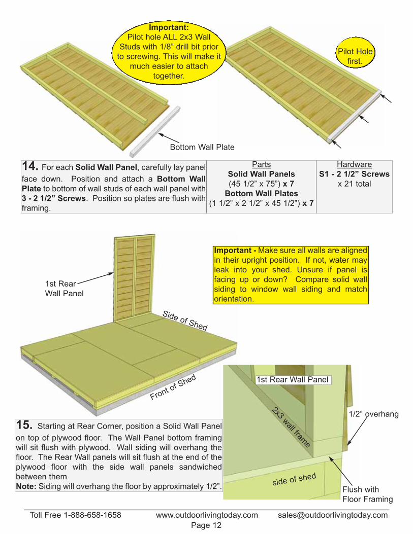
14. For each Solid Wall Panel, carefully lay panel
face down. Position and attach a Bottom Wall
Plate to bottom of wall studs of each wall panel with
3 - 2 1/2” Screws. Position so plates are flush with
framing.
Parts
Solid Wall Panels
(45 1/2” x 75”) x 7
Bottom Wall Plates
(1 1/2” x 2 1/2” x 45 1/2”) x 7
Hardware
S1 - 2 1/2” Screws
x 21 total
Important:
Pilot hole ALL 2x3 Wall
Studs with 1/8” drill bit prior
to screwing. This will make it
much easier to attach
together.
Pilot Hole
first.
Bottom Wall Plate
Side of Shed
15. Starting at Rear Corner, position a Solid Wall Panel
on top of plywood floor. The Wall Panel bottom framing
will sit flush with plywood. Wall siding will overhang the
floor. The Rear Wall panels will sit flush at the end of the
plywood floor with the side wall panels sandwiched
between them
Note: Siding will overhang the floor by approximately 1/2”.
1st Rear
Wall Panel
Front of S
hed 1st Rear Wall Panel
side of shed
2x3 wall fram
e
Flush with
Floor Framing
1/2” overhang
Important - Make sure all walls are aligned
in their upright position. If not, water may
leak into your shed. Unsure if panel is
facing up or down? Compare solid wall
siding to window wall siding and match
orientation.
Toll Free 1-888-658-1658 www.outdoorlivingtoday.com [email protected]
Page 12
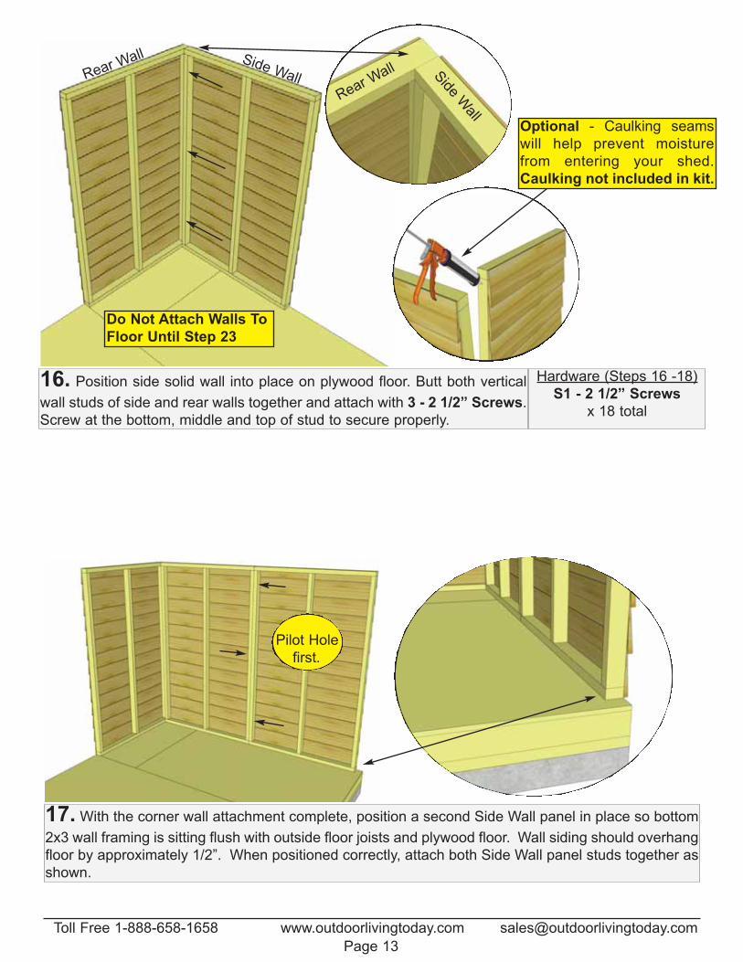
Do Not Attach Walls To
Floor Until Step 23
Side WallRear Wall
Optional - Caulking seams
will help prevent moisture
from entering your shed.
Caulking not included in kit.
16. Position side solid wall into place on plywood floor. Butt both vertical
wall studs of side and rear walls together and attach with 3 - 2 1/2” Screws.
Screw at the bottom, middle and top of stud to secure properly.
Hardware (Steps 16 -18)
S1 - 2 1/2” Screws
x 18 total
Rear Wall S
ide Wall
17. With the corner wall attachment complete, position a second Side Wall panel in place so bottom
2x3 wall framing is sitting flush with outside floor joists and plywood floor. Wall siding should overhang
floor by approximately 1/2”. When positioned correctly, attach both Side Wall panel studs together as
shown.
Pilot Hole
first.
Toll Free 1-888-658-1658 www.outdoorlivingtoday.com [email protected]
Page 13
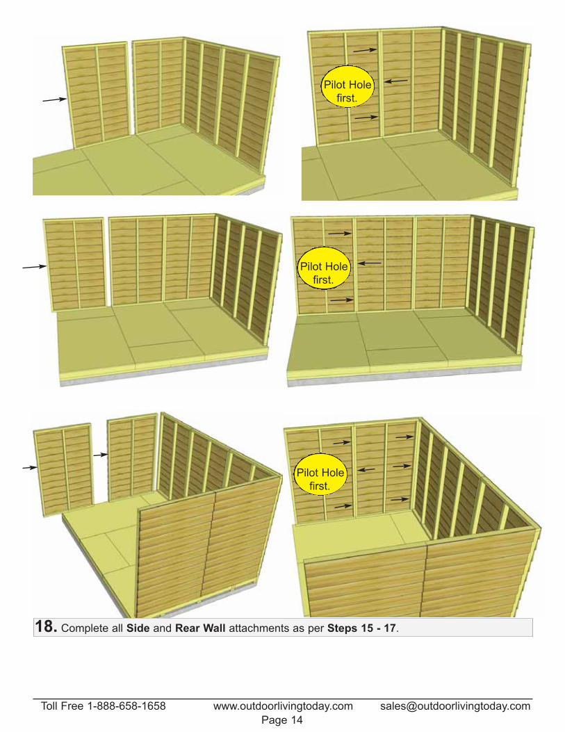
18. Complete all Side and Rear Wall attachments as per Steps 15 - 17.
Pilot Hole
first.
Pilot Hole
first.
Pilot Hole
first.
Toll Free 1-888-658-1658 www.outdoorlivingtoday.com [email protected]
Page 14
Pilot Hole
first.
Pilot Hole
first.
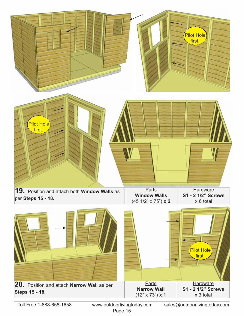
19. Position and attach both Window Walls as
per Steps 15 - 18.
Parts
Window Walls
(45 1/2” x 75”) x 2
Hardware
S1 - 2 1/2” Screws
x 6 total
Pilot Hole
first.
20. Position and attach Narrow Wall as per
Steps 15 - 18.
Parts
Narrow Wall
(12” x 73”) x 1
Hardware
S1 - 2 1/2” Screws
x 3 total
Toll Free 1-888-658-1658 www.outdoorlivingtoday.com [email protected]
Page 15
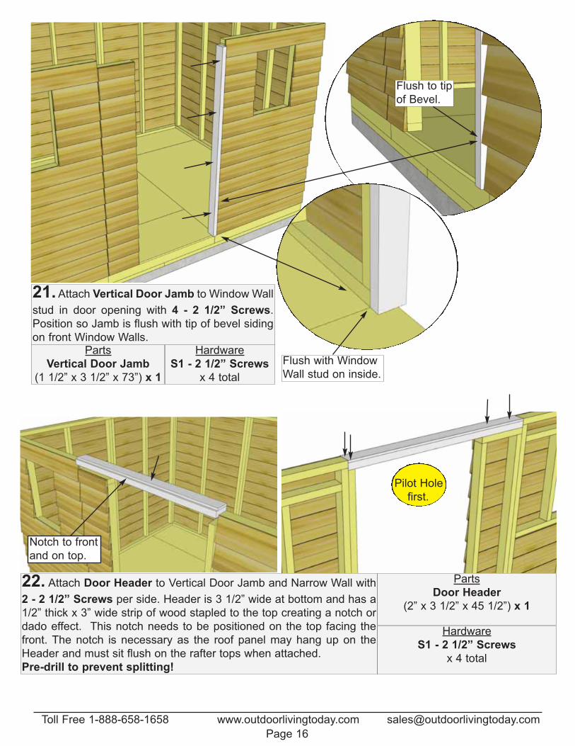
21. Attach Vertical Door Jamb to Window Wall
stud in door opening with 4 - 2 1/2” Screws.
Position so Jamb is flush with tip of bevel siding
on front Window Walls.Parts
Vertical Door Jamb
(1 1/2” x 3 1/2” x 73”) x 1
Hardware
S1 - 2 1/2” Screws
x 4 total
Flush to tip
of Bevel.
Flush with Window
Wall stud on inside.
22. Attach Door Header to Vertical Door Jamb and Narrow Wall with
2 - 2 1/2” Screws per side. Header is 3 1/2” wide at bottom and has a
1/2” thick x 3” wide strip of wood stapled to the top creating a notch or
dado effect. This notch needs to be positioned on the top facing the
front. The notch is necessary as the roof panel may hang up on the
Header and must sit flush on the rafter tops when attached.
Pre-drill to prevent splitting!
Parts
Door Header
(2” x 3 1/2” x 45 1/2”) x 1
Hardware
S1 - 2 1/2” Screws
x 4 total
Notch to front
and on top.
Pilot Hole
first.
Toll Free 1-888-658-1658 www.outdoorlivingtoday.com [email protected]
Page 16
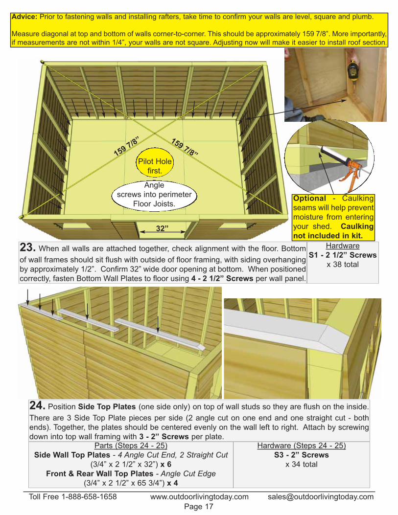
23. When all walls are attached together, check alignment with the floor. Bottom
of wall frames should sit flush with outside of floor framing, with siding overhanging
by approximately 1/2”. Confirm 32” wide door opening at bottom. When positioned
correctly, fasten Bottom Wall Plates to floor using 4 - 2 1/2” Screws per wall panel.
Hardware
S1 - 2 1/2” Screws
x 38 total
24. Position Side Top Plates (one side only) on top of wall studs so they are flush on the inside.
There are 3 Side Top Plate pieces per side (2 angle cut on one end and one straight cut - both
ends). Together, the plates should be centered evenly on the wall left to right. Attach by screwing
down into top wall framing with 3 - 2” Screws per plate.Parts (Steps 24 - 25)
Side Wall Top Plates - 4 Angle Cut End, 2 Straight Cut (3/4” x 2 1/2” x 32”) x 6
Front & Rear Wall Top Plates - Angle Cut Edge
(3/4” x 2 1/2” x 65 3/4”) x 4
Hardware (Steps 24 - 25)
S3 - 2” Screws
x 34 total
159 7/8” 159 7/8”
Angle
screws into perimeter
Floor Joists.
Pilot Hole
first.
32”
Advice: Prior to fastening walls and installing rafters, take time to confirm your walls are level, square and plumb.
Measure diagonal at top and bottom of walls corner-to-corner. This should be approximately 159 7/8”. More importantly,
if measurements are not within 1/4”, your walls are not square. Adjusting now will make it easier to install roof section.
Optional - Caulking
seams will help prevent
moisture from entering
your shed. Caulking
not included in kit.
Toll Free 1-888-658-1658 www.outdoorlivingtoday.com [email protected]
Page 17
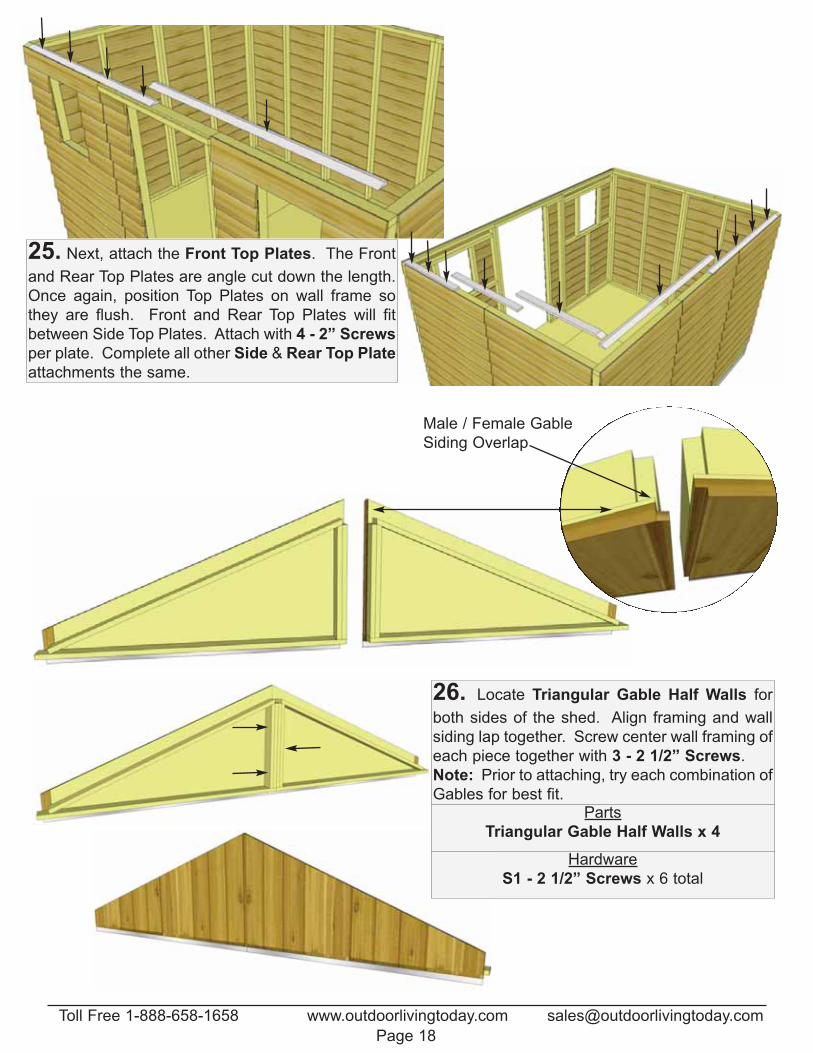
25. Next, attach the Front Top Plates. The Front
and Rear Top Plates are angle cut down the length.
Once again, position Top Plates on wall frame so
they are flush. Front and Rear Top Plates will fit
between Side Top Plates. Attach with 4 - 2” Screws
per plate. Complete all other Side & Rear Top Plate
attachments the same.
Male / Female Gable
Siding Overlap
26. Locate Triangular Gable Half Walls for
both sides of the shed. Align framing and wall
siding lap together. Screw center wall framing of
each piece together with 3 - 2 1/2” Screws.
Note: Prior to attaching, try each combination of
Gables for best fit.Parts
Triangular Gable Half Walls x 4
Hardware
S1 - 2 1/2” Screws x 6 total
Toll Free 1-888-658-1658 www.outdoorlivingtoday.com [email protected]
Page 18
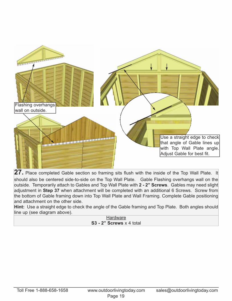
Flashing overhangs
wall on outside.
27. Place completed Gable section so framing sits flush with the inside of the Top Wall Plate. It
should also be centered side-to-side on the Top Wall Plate. Gable Flashing overhangs wall on the
outside. Temporarily attach to Gables and Top Wall Plate with 2 - 2” Screws. Gables may need slight
adjustment in Step 37 when attachment will be completed with an additional 6 Screws. Screw from
the bottom of Gable framing down into Top Wall Plate and Wall Framing. Complete Gable positioning
and attachment on the other side.
Hint: Use a straight edge to check the angle of the Gable framing and Top Plate. Both angles should
line up (see diagram above). Hardware
S3 - 2” Screws x 4 total
Use a straight edge to check
that angle of Gable lines up
with Top Wall Plate angle.
Adjust Gable for best fit.
Toll Free 1-888-658-1658 www.outdoorlivingtoday.com [email protected]
Page 19
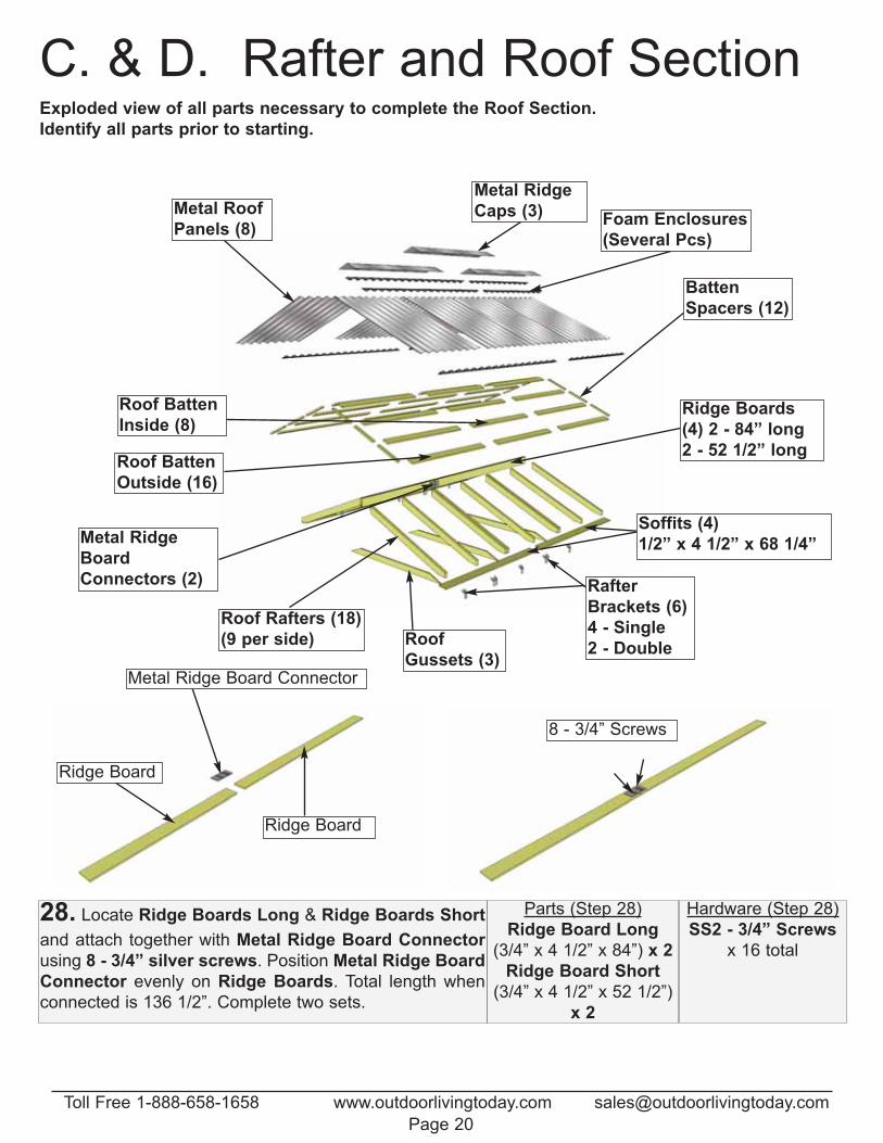
C. & D. Rafter and Roof SectionExploded view of all parts necessary to complete the Roof Section.
Identify all parts prior to starting.
Ridge Board
Ridge Board
Metal Ridge Board Connector
8 - 3/4” Screws
Parts (Step 28)
Ridge Board Long
(3/4” x 4 1/2” x 84”) x 2
Ridge Board Short
(3/4” x 4 1/2” x 52 1/2”)
x 2
Hardware (Step 28)
SS2 - 3/4” Screws
x 16 total
28. Locate Ridge Boards Long & Ridge Boards Short
and attach together with Metal Ridge Board Connector
using 8 - 3/4” silver screws. Position Metal Ridge Board
Connector evenly on Ridge Boards. Total length when
connected is 136 1/2”. Complete two sets.
Metal Ridge
Caps (3)Metal Roof
Panels (8)
Roof Rafters (18)
(9 per side)
Ridge Boards
(4) 2 - 84” long
2 - 52 1/2” long
Soffits (4)
1/2” x 4 1/2” x 68 1/4”Metal Ridge
Board
Connectors (2)
Roof
Gussets (3)
Rafter
Brackets (6)
4 - Single
2 - Double
Foam Enclosures
(Several Pcs)
Batten
Spacers (12)
Roof Batten
Inside (8)
Roof Batten
Outside (16)
Toll Free 1-888-658-1658 www.outdoorlivingtoday.com [email protected]
Page 20
Ridge Board
Soffits
Rafter
Soffit
68 1/4”
45 1/2”20 1/2”
20 1/2”
20 1/2”
45 1/2”45 1/2”
136 1/2”
Connector
Plate to
inside
2 1/2” Screws
into Doubled
up Rafters
Carefully flip
Rafter Sections
over when
complete
Important:
Pilot Hole Ridge
Board to prevent
splitting!
Important:
Pilot Hole Soffit to
prevent splitting!
PreDrill!
PreDrill!
Parts (Steps 29 - 31)
Rafters
(1 1/2” x 3 1/2” x 56 1/2”) x 18
Soffits
(1/2” x 4 1/2” x 68 1/4”) x 4Hardware (Steps 29 - 31)
S1 - 2 1/2” Screws
x 16 total
S2 - 1 1/4” Screws
x 16 total
S3 - 2” Screws
x 16 total
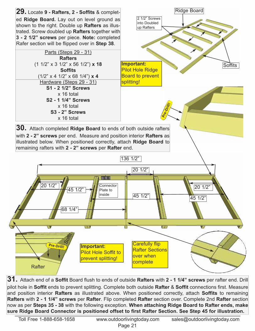
29. Locate 9 - Rafters, 2 - Soffits & complet-
ed Ridge Board. Lay out on level ground as
shown to the right. Double up Rafters as illus-
trated. Screw doubled up Rafters together with
3 - 2 1/2” screws per piece. Note: completed
Rafer section will be flipped over in Step 38.
31. Attach end of a Soffit Board flush to ends of outside Rafters with 2 - 1 1/4” screws per rafter end. Drill
pilot hole in Soffit ends to prevent splitting. Complete both outside Rafter & Soffit connections first. Measure
and position interior Rafters as illustrated above. When positioned correctly, attach Soffits to remaining
Rafters with 2 - 1 1/4” screws per Rafter. Flip completed Rafter section over. Complete 2nd Rafter section
now as per Steps 35 - 38 with the following exception. When attaching Ridge Board to Rafter ends, make
sure Ridge Board Connector is positioned offset to first Rafter Section. See Step 45 for illustration.
30. Attach completed Ridge Board to ends of both outside rafters
with 2 - 2” screws per end. Measure and position interior Rafters as
illustrated below. When positioned correctly, attach Ridge Board to
remaining rafters with 2 - 2” screws per Rafter end.
Toll Free 1-888-658-1658 www.outdoorlivingtoday.com [email protected]
Page 21
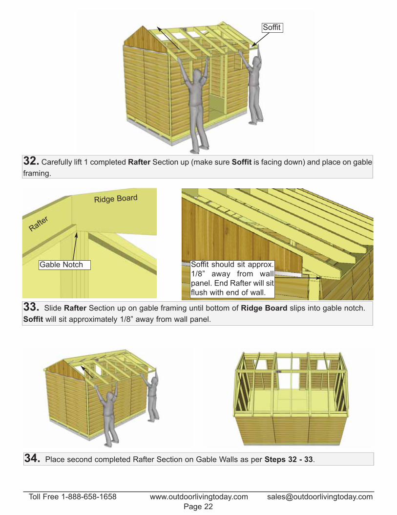
32. Carefully lift 1 completed Rafter Section up (make sure Soffit is facing down) and place on gable
framing.
33. Slide Rafter Section up on gable framing until bottom of Ridge Board slips into gable notch.
Soffit will sit approximately 1/8” away from wall panel.
Soffit
Gable Notch
Ridge Board
Rafter
Soffit should sit approx.
1/8” away from wall
panel. End Rafter will sit
flush with end of wall.
34. Place second completed Rafter Section on Gable Walls as per Steps 32 - 33.
Toll Free 1-888-658-1658 www.outdoorlivingtoday.com [email protected]
Page 22
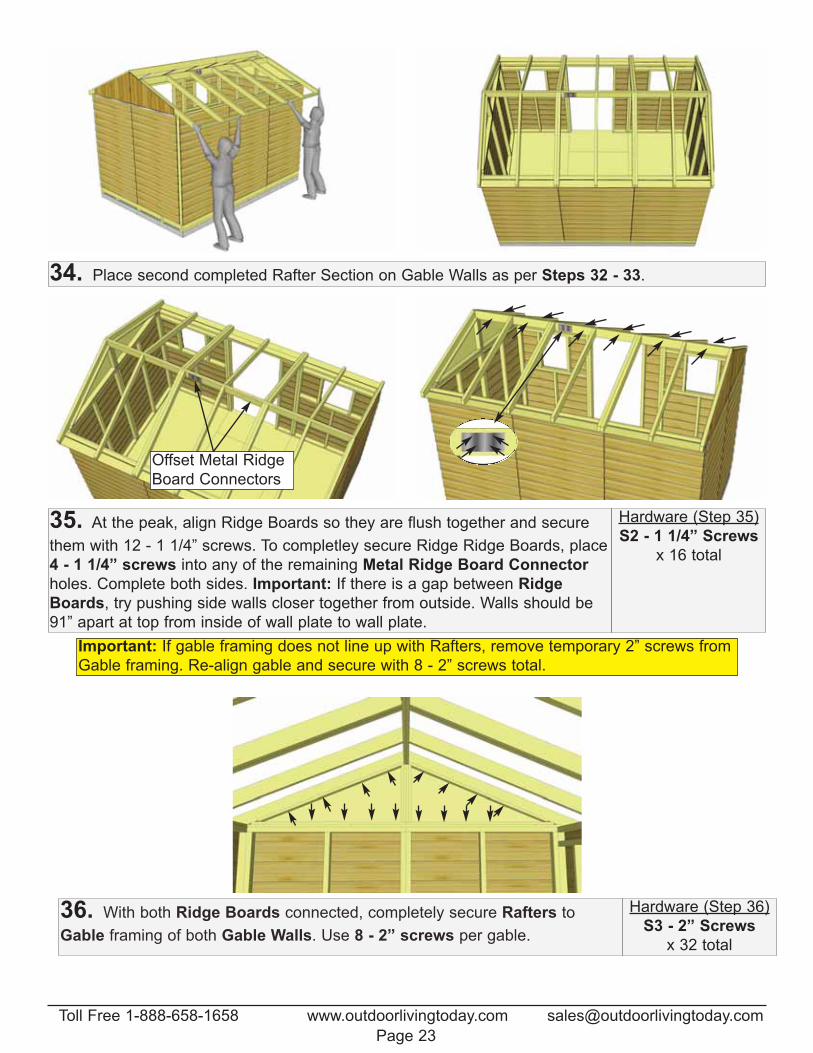
34. Place second completed Rafter Section on Gable Walls as per Steps 32 - 33.
35. At the peak, align Ridge Boards so they are flush together and secure
them with 12 - 1 1/4” screws. To completley secure Ridge Ridge Boards, place
4 - 1 1/4” screws into any of the remaining Metal Ridge Board Connector
holes. Complete both sides. Important: If there is a gap between Ridge
Boards, try pushing side walls closer together from outside. Walls should be
91” apart at top from inside of wall plate to wall plate.
Hardware (Step 35)
S2 - 1 1/4” Screws
x 16 total
Offset Metal Ridge
Board Connectors
Important: If gable framing does not line up with Rafters, remove temporary 2” screws from
Gable framing. Re-align gable and secure with 8 - 2” screws total.
36. With both Ridge Boards connected, completely secure Rafters to
Gable framing of both Gable Walls. Use 8 - 2” screws per gable.
Hardware (Step 36)
S3 - 2” Screws
x 32 total
Toll Free 1-888-658-1658 www.outdoorlivingtoday.com [email protected]
Page 23
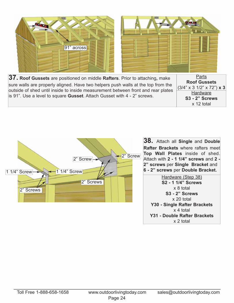
37. Roof Gussets are positioned on middle Rafters. Prior to attaching, make
sure walls are properly aligned. Have two helpers push walls at the top from the
outside of shed until inside to inside measurement between front and rear plates
is 91”. Use a level to square Gusset. Attach Gusset with 4 - 2” screws.
Parts
Roof Gussets
(3/4” x 3 1/2” x 72”) x 3Hardware
S3 - 2” Screws
x 12 total
91” across
38. Attach all Single and Double
Rafter Brackets where rafters meet
Top Wall Plates inside of shed.
Attach with 2 - 1 1/4” screws and 2 -
2” screws per Single Bracket and
6 - 2” screws per Double Bracket.
2” Screws
2” Screw2” Screw
1 1/4” Screw
2” Screws
1 1/4” ScrewHardware (Step 38)
S2 - 1 1/4” Screws
x 8 total
S3 - 2” Screws
x 20 total
Y30 - Single Rafter Brackets
x 4 total
Y31 - Double Rafter Brackets
x 2 total
Toll Free 1-888-658-1658 www.outdoorlivingtoday.com [email protected]
Page 24
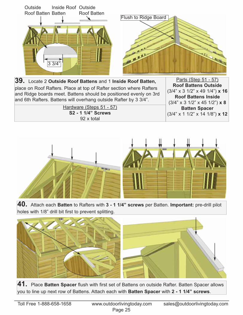
39. Locate 2 Outside Roof Battens and 1 Inside Roof Batten,
place on Roof Rafters. Place at top of Rafter section where Rafters
and Ridge boards meet. Battens should be positioned evenly on 3rd
and 6th Rafters. Battens will overhang outside Rafter by 3 3/4”.
Parts (Step 51 - 57)
Roof Battens Outside
(3/4” x 3 1/2” x 49 1/4”) x 16
Roof Battens Inside
(3/4” x 3 1/2” x 45 1/2”) x 8
Batten Spacer
(3/4” x 1 1/2” x 14 1/8”) x 12
Hardware (Steps 51 - 57)
S2 - 1 1/4” Screws
92 x total
3 3/4”
Flush to Ridge Board
40. Attach each Batten to Rafters with 3 - 1 1/4” screws per Batten. Important: pre-drill pilot
holes with 1/8” drill bit first to prevent splitting.
41. Place Batten Spacer flush with first set of Battens on outside Rafter. Batten Spacer allows
you to line up next row of Battens. Attach each with Batten Spacer with 2 - 1 1/4” screws.
Outside
Roof Batten
Outside
Roof Batten
Inside Roof
Batten
Toll Free 1-888-658-1658 www.outdoorlivingtoday.com [email protected]
Page 25
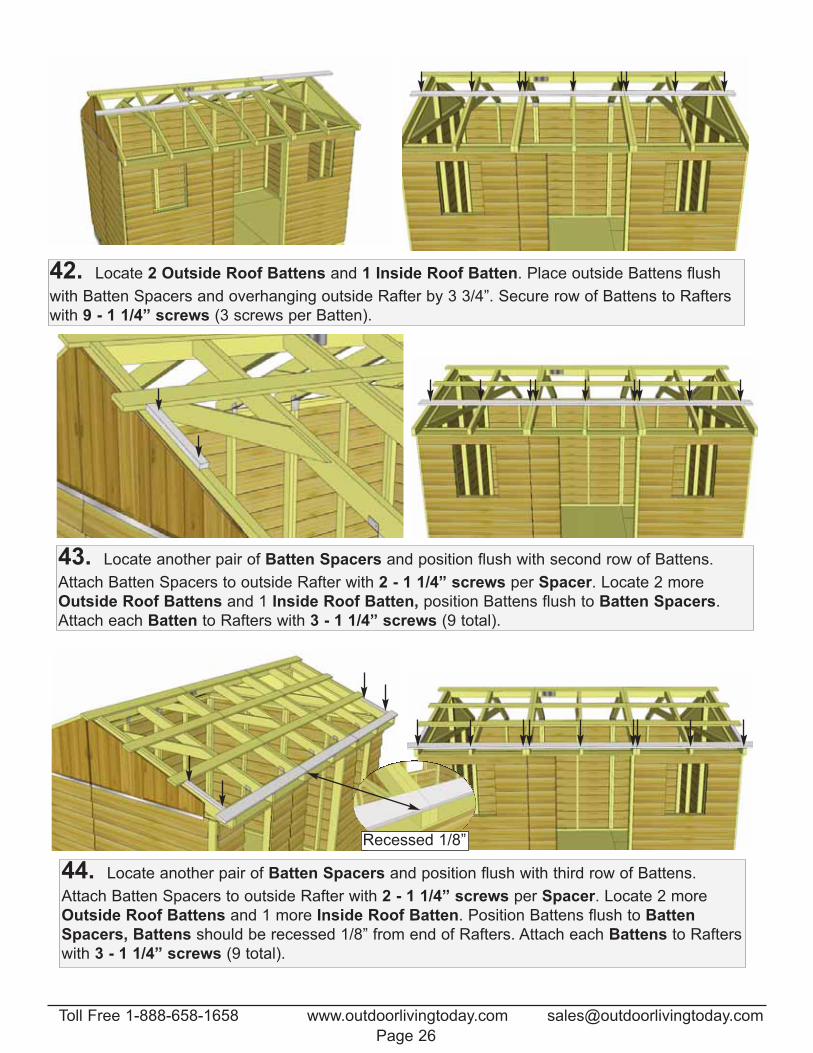
42. Locate 2 Outside Roof Battens and 1 Inside Roof Batten. Place outside Battens flush
with Batten Spacers and overhanging outside Rafter by 3 3/4”. Secure row of Battens to Rafters
with 9 - 1 1/4” screws (3 screws per Batten).
43. Locate another pair of Batten Spacers and position flush with second row of Battens.
Attach Batten Spacers to outside Rafter with 2 - 1 1/4” screws per Spacer. Locate 2 more
Outside Roof Battens and 1 Inside Roof Batten, position Battens flush to Batten Spacers.
Attach each Batten to Rafters with 3 - 1 1/4” screws (9 total).
44. Locate another pair of Batten Spacers and position flush with third row of Battens.
Attach Batten Spacers to outside Rafter with 2 - 1 1/4” screws per Spacer. Locate 2 more
Outside Roof Battens and 1 more Inside Roof Batten. Position Battens flush to Batten
Spacers, Battens should be recessed 1/8” from end of Rafters. Attach each Battens to Rafters
with 3 - 1 1/4” screws (9 total).
Recessed 1/8”
Toll Free 1-888-658-1658 www.outdoorlivingtoday.com [email protected]
Page 26
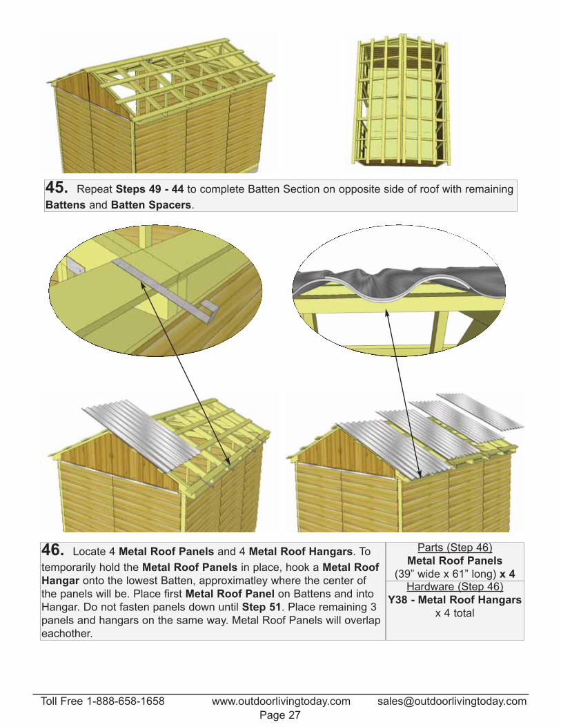
45. Repeat Steps 49 - 44 to complete Batten Section on opposite side of roof with remaining
Battens and Batten Spacers.
46. Locate 4 Metal Roof Panels and 4 Metal Roof Hangars. To
temporarily hold the Metal Roof Panels in place, hook a Metal Roof
Hangar onto the lowest Batten, approximatley where the center of
the panels will be. Place first Metal Roof Panel on Battens and into
Hangar. Do not fasten panels down until Step 51. Place remaining 3
panels and hangars on the same way. Metal Roof Panels will overlap
eachother.
Parts (Step 46)
Metal Roof Panels
(39” wide x 61” long) x 4Hardware (Step 46)
Y38 - Metal Roof Hangars
x 4 total
Toll Free 1-888-658-1658 www.outdoorlivingtoday.com [email protected]
Page 27
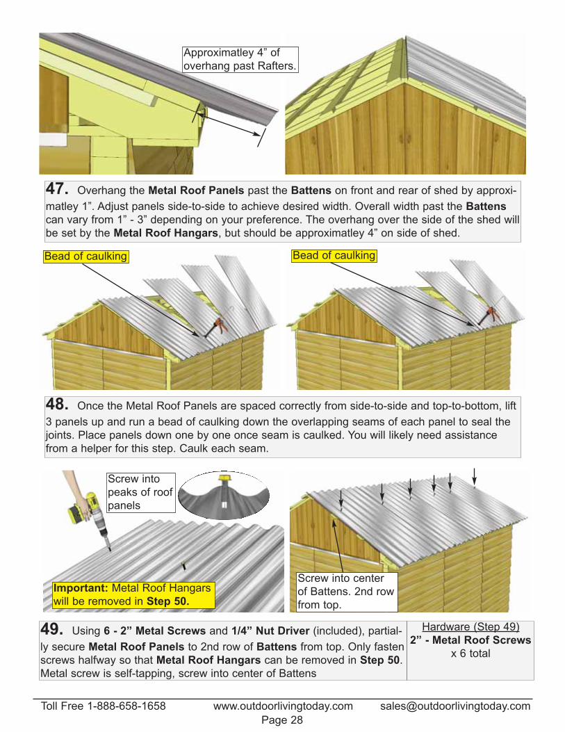
47. Overhang the Metal Roof Panels past the Battens on front and rear of shed by approxi-
matley 1”. Adjust panels side-to-side to achieve desired width. Overall width past the Battens
can vary from 1” - 3” depending on your preference. The overhang over the side of the shed will
be set by the Metal Roof Hangars, but should be approximatley 4” on side of shed.
Approximatley 4” of
overhang past Rafters.
48. Once the Metal Roof Panels are spaced correctly from side-to-side and top-to-bottom, lift
3 panels up and run a bead of caulking down the overlapping seams of each panel to seal the
joints. Place panels down one by one once seam is caulked. You will likely need assistance
from a helper for this step. Caulk each seam.
Bead of caulking Bead of caulking
49. Using 6 - 2” Metal Screws and 1/4” Nut Driver (included), partial-
ly secure Metal Roof Panels to 2nd row of Battens from top. Only fasten
screws halfway so that Metal Roof Hangars can be removed in Step 50.
Metal screw is self-tapping, screw into center of Battens
Hardware (Step 49)
2” - Metal Roof Screws
x 6 total
Important: Metal Roof Hangars
will be removed in Step 50.
Screw into center
of Battens. 2nd row
from top.
Screw into
peaks of roof
panels
Toll Free 1-888-658-1658 www.outdoorlivingtoday.com [email protected]
Page 28
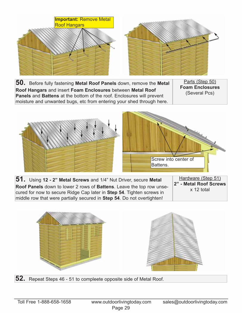
50. Before fully fastening Metal Roof Panels down, remove the Metal
Roof Hangars and insert Foam Enclosures between Metal Roof
Panels and Battens at the bottom of the roof. Enclosures will prevent
moisture and unwanted bugs, etc from entering your shed through here.
Parts (Step 50)
Foam Enclosures
(Several Pcs)
Important: Remove Metal
Roof Hangars
51. Using 12 - 2” Metal Screws and 1/4” Nut Driver, secure Metal
Roof Panels down to lower 2 rows of Battens. Leave the top row unse-
cured for now to secure Ridge Cap later in Step 54. Tighten screws in
middle row that were partially secured in Step 54. Do not overtighten!
Hardware (Step 51)
2” - Metal Roof Screws
x 12 total
Screw into center of
Battens.
52. Repeat Steps 46 - 51 to compleete opposite side of Metal Roof.
Toll Free 1-888-658-1658 www.outdoorlivingtoday.com [email protected]
Page 29
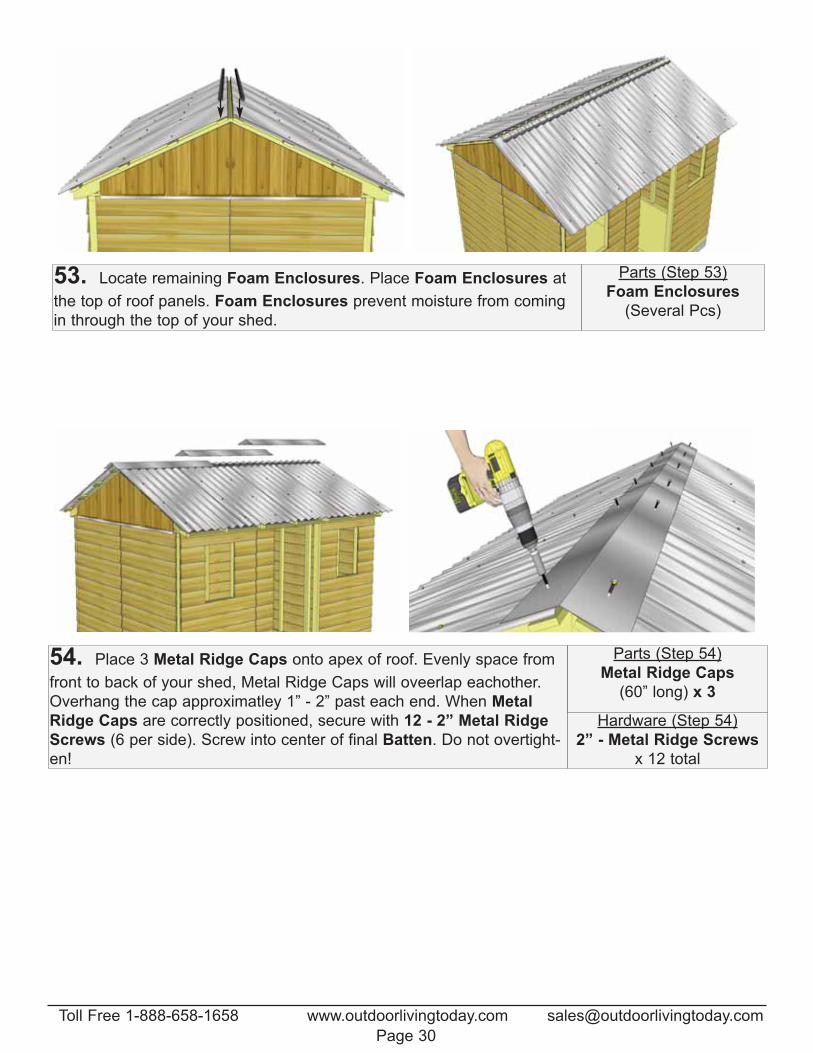
53. Locate remaining Foam Enclosures. Place Foam Enclosures at
the top of roof panels. Foam Enclosures prevent moisture from coming
in through the top of your shed.
Parts (Step 53)
Foam Enclosures
(Several Pcs)
Hardware (Step 54)
2” - Metal Ridge Screws
x 12 total
54. Place 3 Metal Ridge Caps onto apex of roof. Evenly space from
front to back of your shed, Metal Ridge Caps will oveerlap eachother.
Overhang the cap approximatley 1” - 2” past each end. When Metal
Ridge Caps are correctly positioned, secure with 12 - 2” Metal Ridge
Screws (6 per side). Screw into center of final Batten. Do not overtight-
en!
Parts (Step 54)
Metal Ridge Caps
(60” long) x 3
Toll Free 1-888-658-1658 www.outdoorlivingtoday.com [email protected]
Page 30
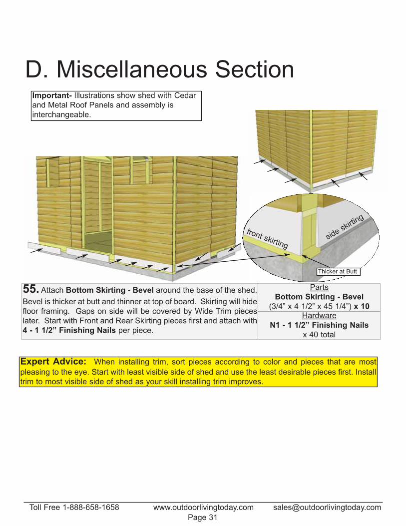
55. Attach Bottom Skirting - Bevel around the base of the shed.
Bevel is thicker at butt and thinner at top of board. Skirting will hide
floor framing. Gaps on side will be covered by Wide Trim pieces
later. Start with Front and Rear Skirting pieces first and attach with
4 - 1 1/2” Finishing Nails per piece.
Parts
Bottom Skirting - Bevel
(3/4” x 4 1/2” x 45 1/4”) x 10Hardware
N1 - 1 1/2” Finishing Nails
x 40 total
Expert Advice: When installing trim, sort pieces according to color and pieces that are most
pleasing to the eye. Start with least visible side of shed and use the least desirable pieces first. Install
trim to most visible side of shed as your skill installing trim improves.
D. Miscellaneous Section
side skirting
Thicker at Butt
front skirting
Important- Illustrations show shed with Cedar
and Metal Roof Panels and assembly is
interchangeable.
Toll Free 1-888-658-1658 www.outdoorlivingtoday.com [email protected]
Page 31
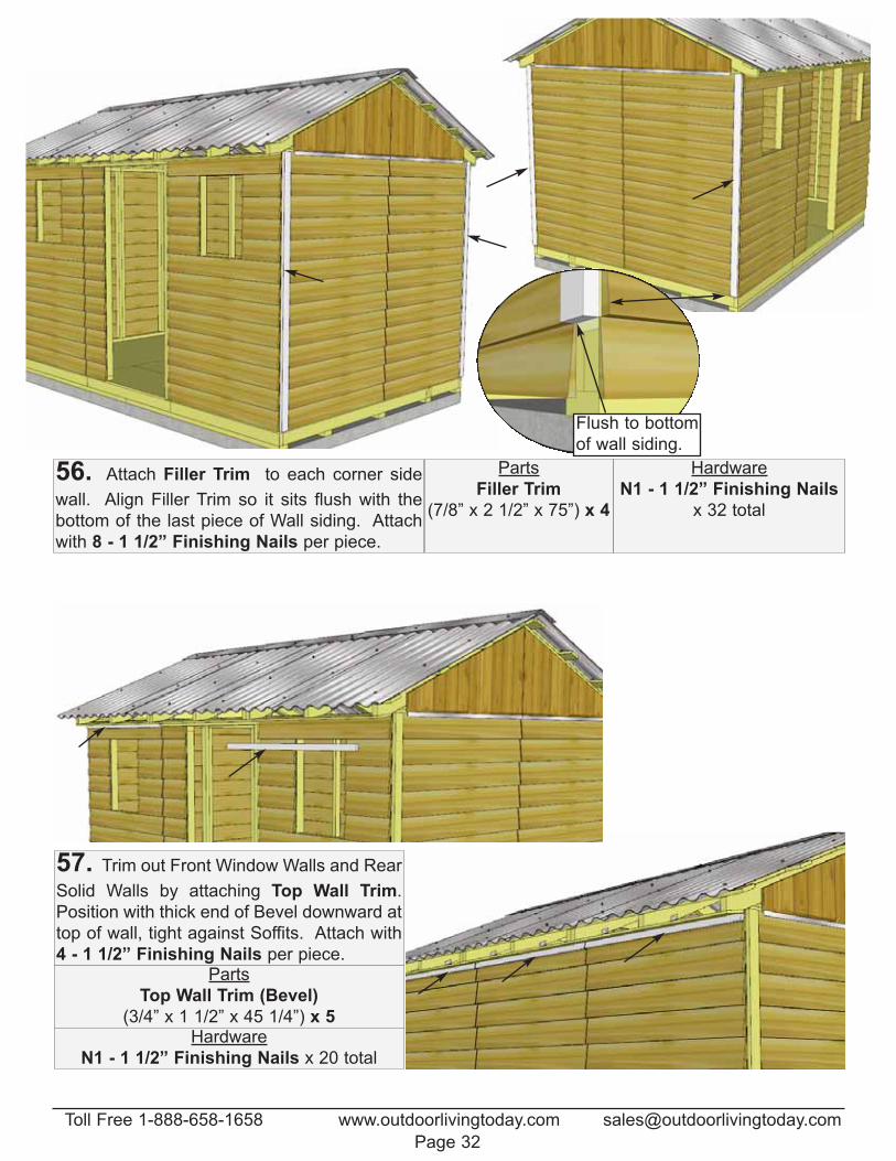
56. Attach Filler Trim to each corner side
wall. Align Filler Trim so it sits flush with the
bottom of the last piece of Wall siding. Attach
with 8 - 1 1/2” Finishing Nails per piece.
Parts
Filler Trim
(7/8” x 2 1/2” x 75”) x 4
Hardware
N1 - 1 1/2” Finishing Nails
x 32 total
Flush to bottom
of wall siding.
57. Trim out Front Window Walls and Rear
Solid Walls by attaching Top Wall Trim.
Position with thick end of Bevel downward at
top of wall, tight against Soffits. Attach with
4 - 1 1/2” Finishing Nails per piece.Parts
Top Wall Trim (Bevel)
(3/4” x 1 1/2” x 45 1/4”) x 5Hardware
N1 - 1 1/2” Finishing Nails x 20 total
Toll Free 1-888-658-1658 www.outdoorlivingtoday.com [email protected]
Page 32
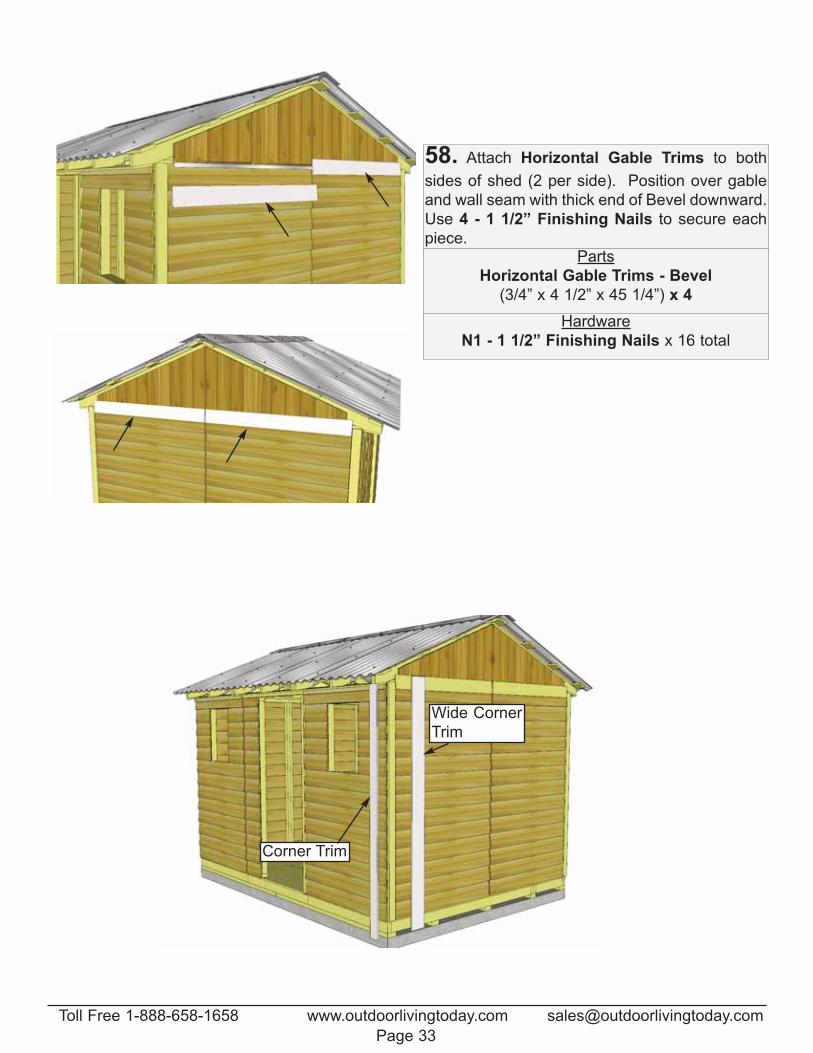
58. Attach Horizontal Gable Trims to both
sides of shed (2 per side). Position over gable
and wall seam with thick end of Bevel downward.
Use 4 - 1 1/2” Finishing Nails to secure each
piece.Parts
Horizontal Gable Trims - Bevel
(3/4” x 4 1/2” x 45 1/4”) x 4
Hardware
N1 - 1 1/2” Finishing Nails x 16 total
Corner Trim
Wide Corner
Trim
Toll Free 1-888-658-1658 www.outdoorlivingtoday.com [email protected]
Page 33
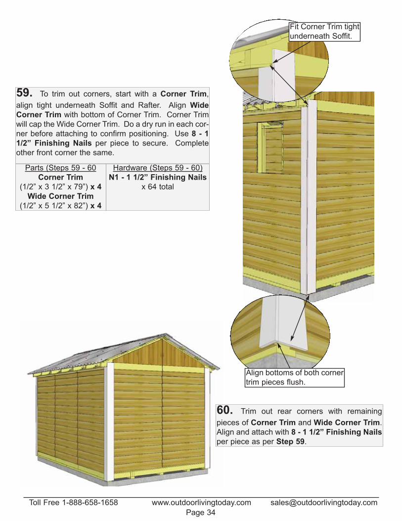
60. Trim out rear corners with remaining
pieces of Corner Trim and Wide Corner Trim.
Align and attach with 8 - 1 1/2” Finishing Nails
per piece as per Step 59.
Align bottoms of both corner
trim pieces flush.
Fit Corner Trim tight
underneath Soffit.
59. To trim out corners, start with a Corner Trim,
align tight underneath Soffit and Rafter. Align Wide
Corner Trim with bottom of Corner Trim. Corner Trim
will cap the Wide Corner Trim. Do a dry run in each cor-
ner before attaching to confirm positioning. Use 8 - 1
1/2” Finishing Nails per piece to secure. Complete
other front corner the same.
Parts (Steps 59 - 60
Corner Trim
(1/2” x 3 1/2” x 79”) x 4
Wide Corner Trim
(1/2” x 5 1/2” x 82”) x 4
Hardware (Steps 59 - 60)
N1 - 1 1/2” Finishing Nails
x 64 total
Toll Free 1-888-658-1658 www.outdoorlivingtoday.com [email protected]
Page 34
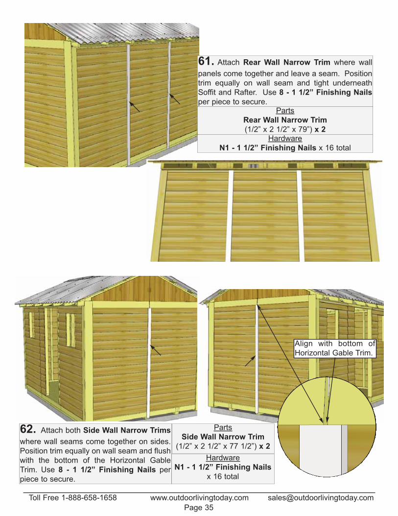
61. Attach Rear Wall Narrow Trim where wall
panels come together and leave a seam. Position
trim equally on wall seam and tight underneath
Soffit and Rafter. Use 8 - 1 1/2” Finishing Nails
per piece to secure.Parts
Rear Wall Narrow Trim
(1/2” x 2 1/2” x 79”) x 2Hardware
N1 - 1 1/2” Finishing Nails x 16 total
Align with bottom of
Horizontal Gable Trim.
62. Attach both Side Wall Narrow Trims
where wall seams come together on sides.
Position trim equally on wall seam and flush
with the bottom of the Horizontal Gable
Trim. Use 8 - 1 1/2” Finishing Nails per
piece to secure.
Parts
Side Wall Narrow Trim
(1/2” x 2 1/2” x 77 1/2”) x 2
Hardware
N1 - 1 1/2” Finishing Nails
x 16 total
Toll Free 1-888-658-1658 www.outdoorlivingtoday.com [email protected]
Page 35
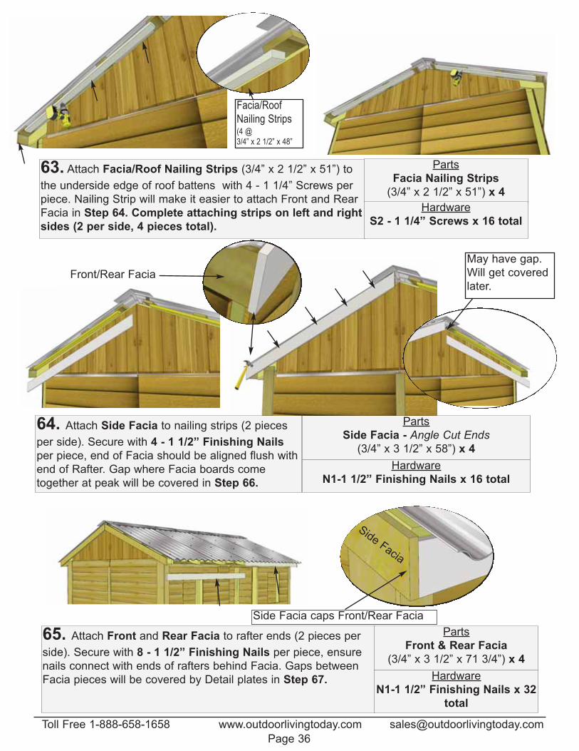
63. Attach Facia/Roof Nailing Strips (3/4” x 2 1/2” x 51”) to
the underside edge of roof battens with 4 - 1 1/4” Screws per
piece. Nailing Strip will make it easier to attach Front and Rear
Facia in Step 64. Complete attaching strips on left and right
sides (2 per side, 4 pieces total).
Facia/Roof Nailing Strips (4 @ 3/4” x 2 1/2” x 48”
64. Attach Side Facia to nailing strips (2 pieces
per side). Secure with 4 - 1 1/2” Finishing Nails
per piece, end of Facia should be aligned flush with
end of Rafter. Gap where Facia boards come
together at peak will be covered in Step 66.
Front/Rear Facia
May have gap.
Will get covered
later.
Parts
Facia Nailing Strips
(3/4” x 2 1/2” x 51”) x 4
Hardware
S2 - 1 1/4” Screws x 16 total
Parts
Side Facia - Angle Cut Ends
(3/4” x 3 1/2” x 58”) x 4
Hardware
N1-1 1/2” Finishing Nails x 16 total
65. Attach Front and Rear Facia to rafter ends (2 pieces per
side). Secure with 8 - 1 1/2” Finishing Nails per piece, ensure
nails connect with ends of rafters behind Facia. Gaps between
Facia pieces will be covered by Detail plates in Step 67.
Parts
Front & Rear Facia
(3/4” x 3 1/2” x 71 3/4”) x 4
Hardware
N1-1 1/2” Finishing Nails x 32
total
Side Facia
Side Facia caps Front/Rear Facia
Toll Free 1-888-658-1658 www.outdoorlivingtoday.com [email protected]
Page 36
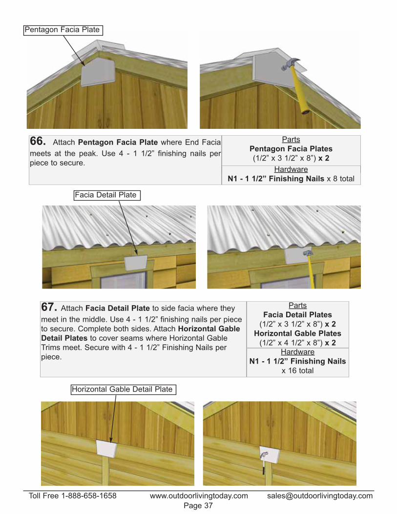
Pentagon Facia Plate
66. Attach Pentagon Facia Plate where End Facia
meets at the peak. Use 4 - 1 1/2” finishing nails per
piece to secure.
67. Attach Facia Detail Plate to side facia where they
meet in the middle. Use 4 - 1 1/2” finishing nails per piece
to secure. Complete both sides. Attach Horizontal Gable
Detail Plates to cover seams where Horizontal Gable
Trims meet. Secure with 4 - 1 1/2” Finishing Nails per
piece.
Parts
Facia Detail Plates
(1/2” x 3 1/2” x 8”) x 2
Horizontal Gable Plates
(1/2” x 4 1/2” x 8”) x 2Hardware
N1 - 1 1/2” Finishing Nails
x 16 total
Facia Detail Plate
Horizontal Gable Detail Plate
Parts
Pentagon Facia Plates
(1/2” x 3 1/2” x 8”) x 2
Hardware
N1 - 1 1/2” Finishing Nails x 8 total
Toll Free 1-888-658-1658 www.outdoorlivingtoday.com [email protected]
Page 37
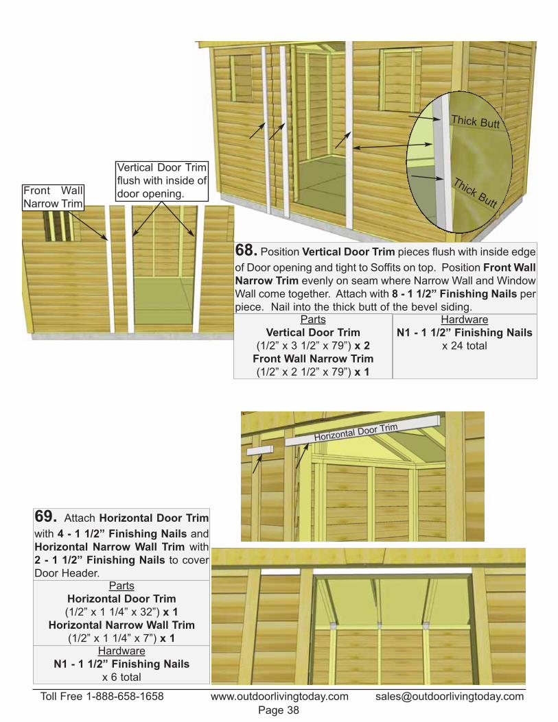
Horizontal Door Trim
69. Attach Horizontal Door Trim
with 4 - 1 1/2” Finishing Nails and
Horizontal Narrow Wall Trim with
2 - 1 1/2” Finishing Nails to cover
Door Header.Parts
Horizontal Door Trim
(1/2” x 1 1/4” x 32”) x 1
Horizontal Narrow Wall Trim
(1/2” x 1 1/4” x 7”) x 1Hardware
N1 - 1 1/2” Finishing Nails
x 6 total
Thick Butt
Thick Butt
Vertical Door Trim
flush with inside of
door opening.Front Wall
Narrow Trim
68. Position Vertical Door Trim pieces flush with inside edge
of Door opening and tight to Soffits on top. Position Front Wall
Narrow Trim evenly on seam where Narrow Wall and Window
Wall come together. Attach with 8 - 1 1/2” Finishing Nails per
piece. Nail into the thick butt of the bevel siding.Parts
Vertical Door Trim
(1/2” x 3 1/2” x 79”) x 2
Front Wall Narrow Trim
(1/2” x 2 1/2” x 79”) x 1
Hardware
N1 - 1 1/2” Finishing Nails
x 24 total
Toll Free 1-888-658-1658 www.outdoorlivingtoday.com [email protected]
Page 38
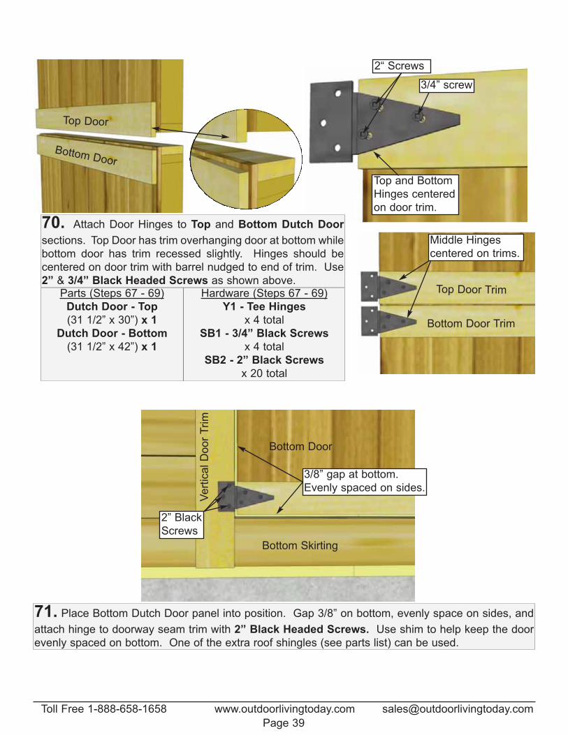
Top Door
Bottom Door
Top and Bottom
Hinges centered
on door trim.
Top Door Trim
Bottom Door Trim
Middle Hinges
centered on trims.
2“ Screws
3/4” screw
70. Attach Door Hinges to Top and Bottom Dutch Door
sections. Top Door has trim overhanging door at bottom while
bottom door has trim recessed slightly. Hinges should be
centered on door trim with barrel nudged to end of trim. Use
2” & 3/4” Black Headed Screws as shown above. Parts (Steps 67 - 69)
Dutch Door - Top
(31 1/2” x 30”) x 1
Dutch Door - Bottom
(31 1/2” x 42”) x 1
Hardware (Steps 67 - 69)
Y1 - Tee Hinges
x 4 total
SB1 - 3/4” Black Screws
x 4 total
SB2 - 2” Black Screws
x 20 total
Bottom Skirting
Bottom Door
3/8” gap at bottom.
Evenly spaced on sides.
Vert
ical D
oor
Trim
2” Black
Screws
71. Place Bottom Dutch Door panel into position. Gap 3/8” on bottom, evenly space on sides, and
attach hinge to doorway seam trim with 2” Black Headed Screws. Use shim to help keep the door
evenly spaced on bottom. One of the extra roof shingles (see parts list) can be used.
Toll Free 1-888-658-1658 www.outdoorlivingtoday.com [email protected]
Page 39
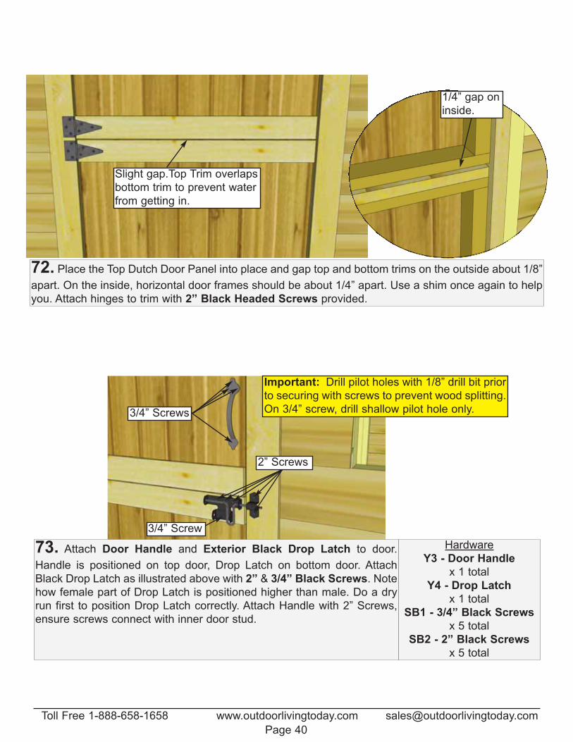
Slight gap.Top Trim overlaps
bottom trim to prevent water
from getting in.
1/4” gap on
inside.
2” Screws
3/4” Screw
Important: Drill pilot holes with 1/8” drill bit prior
to securing with screws to prevent wood splitting.
On 3/4” screw, drill shallow pilot hole only.3/4” Screws
72. Place the Top Dutch Door Panel into place and gap top and bottom trims on the outside about 1/8”
apart. On the inside, horizontal door frames should be about 1/4” apart. Use a shim once again to help
you. Attach hinges to trim with 2” Black Headed Screws provided.
73. Attach Door Handle and Exterior Black Drop Latch to door.
Handle is positioned on top door, Drop Latch on bottom door. Attach
Black Drop Latch as illustrated above with 2” & 3/4” Black Screws. Note
how female part of Drop Latch is positioned higher than male. Do a dry
run first to position Drop Latch correctly. Attach Handle with 2” Screws,
ensure screws connect with inner door stud.
Hardware
Y3 - Door Handle
x 1 total
Y4 - Drop Latch
x 1 total
SB1 - 3/4” Black Screws
x 5 total
SB2 - 2” Black Screws
x 5 total
Toll Free 1-888-658-1658 www.outdoorlivingtoday.com [email protected]
Page 40
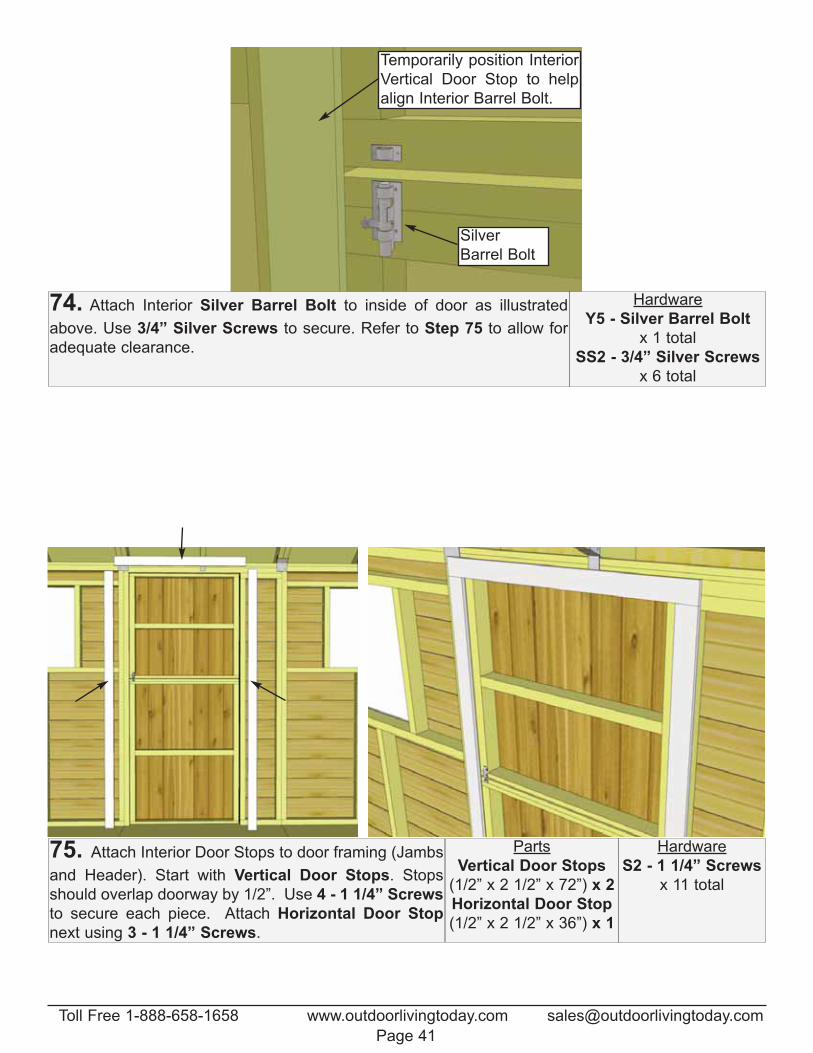
Temporarily position Interior
Vertical Door Stop to help
align Interior Barrel Bolt.
Silver
Barrel Bolt
74. Attach Interior Silver Barrel Bolt to inside of door as illustrated
above. Use 3/4” Silver Screws to secure. Refer to Step 75 to allow for
adequate clearance.
Hardware
Y5 - Silver Barrel Bolt
x 1 total
SS2 - 3/4” Silver Screws
x 6 total
75. Attach Interior Door Stops to door framing (Jambs
and Header). Start with Vertical Door Stops. Stops
should overlap doorway by 1/2”. Use 4 - 1 1/4” Screws
to secure each piece. Attach Horizontal Door Stop
next using 3 - 1 1/4” Screws.
Parts
Vertical Door Stops
(1/2” x 2 1/2” x 72”) x 2
Horizontal Door Stop
(1/2” x 2 1/2” x 36”) x 1
Hardware
S2 - 1 1/4” Screws
x 11 total
Toll Free 1-888-658-1658 www.outdoorlivingtoday.com [email protected]
Page 41
Thi
ck b
utt o
f sid
ing
Caulk
gap.
Trim dado sits
in flange.
Trim
dado
Caulk
gap.
Window
frame.
Siding ButtScrew insert into
bottom (thick)
part of siding.
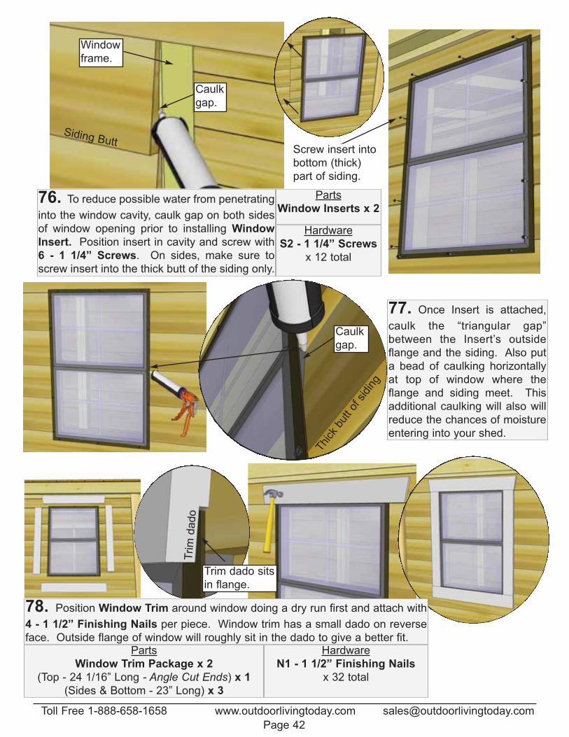
76. To reduce possible water from penetrating
into the window cavity, caulk gap on both sides
of window opening prior to installing Window
Insert. Position insert in cavity and screw with
6 - 1 1/4” Screws. On sides, make sure to
screw insert into the thick butt of the siding only.
Parts
Window Inserts x 2
Hardware
S2 - 1 1/4” Screws
x 12 total
77. Once Insert is attached,
caulk the “triangular gap”
between the Insert’s outside
flange and the siding. Also put
a bead of caulking horizontally
at top of window where the
flange and siding meet. This
additional caulking will also will
reduce the chances of moisture
entering into your shed.
78. Position Window Trim around window doing a dry run first and attach with
4 - 1 1/2” Finishing Nails per piece. Window trim has a small dado on reverse
face. Outside flange of window will roughly sit in the dado to give a better fit. Parts
Window Trim Package x 2
(Top - 24 1/16” Long - Angle Cut Ends) x 1
(Sides & Bottom - 23” Long) x 3
Hardware
N1 - 1 1/2” Finishing Nails
x 32 total
Toll Free 1-888-658-1658 www.outdoorlivingtoday.com [email protected]
Page 42
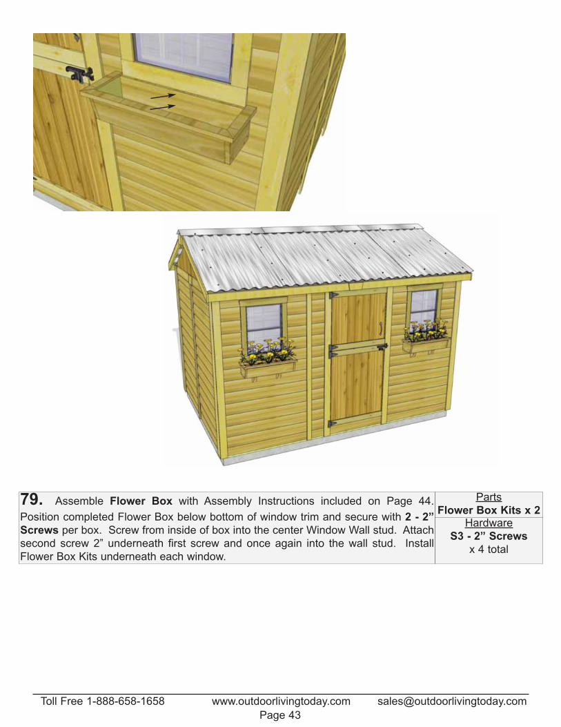
79. Assemble Flower Box with Assembly Instructions included on Page 44.
Position completed Flower Box below bottom of window trim and secure with 2 - 2”
Screws per box. Screw from inside of box into the center Window Wall stud. Attach
second screw 2” underneath first screw and once again into the wall stud. Install
Flower Box Kits underneath each window.
Parts
Flower Box Kits x 2Hardware
S3 - 2” Screws
x 4 total
Toll Free 1-888-658-1658 www.outdoorlivingtoday.com [email protected]
Page 43
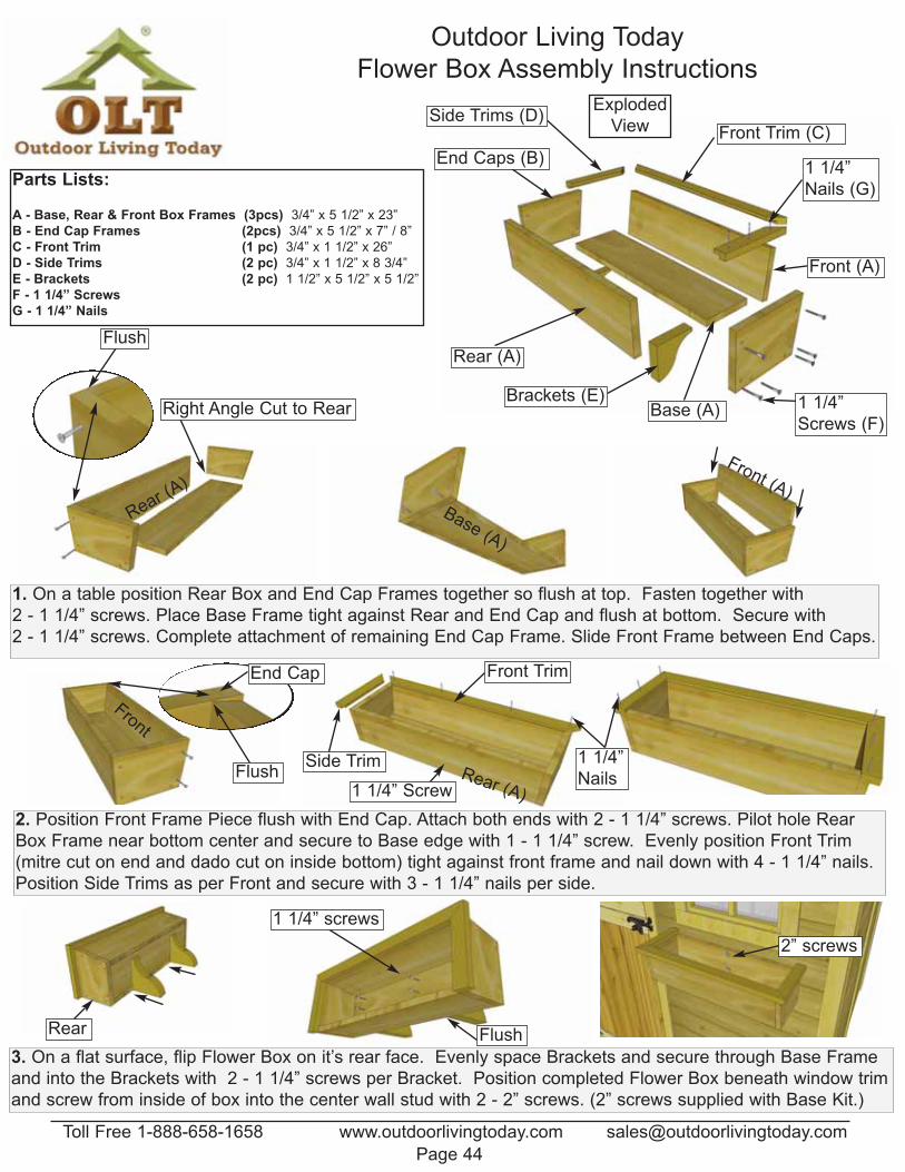
Outdoor Living Today
Flower Box Assembly Instructions
2. Position Front Frame Piece flush with End Cap. Attach both ends with 2 - 1 1/4” screws. Pilot hole Rear
Box Frame near bottom center and secure to Base edge with 1 - 1 1/4” screw. Evenly position Front Trim
(mitre cut on end and dado cut on inside bottom) tight against front frame and nail down with 4 - 1 1/4” nails.
Position Side Trims as per Front and secure with 3 - 1 1/4” nails per side.
1. On a table position Rear Box and End Cap Frames together so flush at top. Fasten together with
2 - 1 1/4” screws. Place Base Frame tight against Rear and End Cap and flush at bottom. Secure with
2 - 1 1/4” screws. Complete attachment of remaining End Cap Frame. Slide Front Frame between End Caps.
3. On a flat surface, flip Flower Box on it’s rear face. Evenly space Brackets and secure through Base Frame
and into the Brackets with 2 - 1 1/4” screws per Bracket. Position completed Flower Box beneath window trim
and screw from inside of box into the center wall stud with 2 - 2” screws. (2” screws supplied with Base Kit.)
Parts Lists:
A - Base, Rear & Front Box Frames (3pcs) 3/4” x 5 1/2” x 23”
B - End Cap Frames (2pcs) 3/4” x 5 1/2” x 7” / 8”
C - Front Trim (1 pc) 3/4” x 1 1/2” x 26”
D - Side Trims (2 pc) 3/4” x 1 1/2” x 8 3/4”
E - Brackets (2 pc) 1 1/2” x 5 1/2” x 5 1/2”
F - 1 1/4” Screws
G - 1 1/4” Nails
Rear (A)
Front (A)
Base (A)
End Caps (B)
Front Trim (C)Side Trims (D)
Brackets (E) 1 1/4”
Screws (F)
1 1/4”
Nails (G)
Rear (A)
Right Angle Cut to Rear
Flush
Base (A)
Front (A)
End Cap
Front
Flush
Front Trim
Side Trim
Rear
1 1/4” screws
Flush
2” screws
Exploded
View
1 1/4” ScrewRear (A)
1 1/4”
Nails
Toll Free 1-888-658-1658 www.outdoorlivingtoday.com [email protected]
Page 44

Congratulations on assembling
your 12x8 Cabana!
Note: Our Sheds are shipped as unfinished products. If exposed to the elements, the western red
cedar lumber will weather to a silvery-gray color. If you prefer to keep the cedar lumber looking
closer to the original color, we suggest that you treat the wood with a good oil base wood stain. You
may also wish to paint your new shed rather than stain it. In both cases we recommend that you
consult with a paint and stain dealer in your area for their recommendations.
The materials contained in this
Assembly Manual may be downloaded
or copied provided that ALL copies
retain the copyright and any other
proprietary notices contained on the
materials. No material may be
modified, edited or taken out of context
such that its use creates a false or
misleading statement or impression as
to the positions, statements or actions.
Canadian Address 9393 287th Street Maple Ridge, British Columbia Canada V2W 1L1
United States Address P.O. Box 96 Sumas, Washington USA 98295
Outdoor Living TodayPlease call, write or email us at:
We value your feedback and
would like to hear back from you
on how well we are doing in the
following areas:
1. Customer Service
2. On Time Shipping
3. Motor Freight Delivery
4. Quality of Materials
5. Assembly Manual
6. Overall Satisfaction.
We hope your experience
assembling your 12x8 Cabana
Garden Shed has been both
positive and rewarding.
Toll Line: 1.888.658.1658 | Fax: 1.604.462.5333 | [email protected]
Page 45