vcdc:thevirtualizedcomplicateddevice controller -...
TRANSCRIPT
VCDC: The Virtualized Complicated DeviceControllerZhe Jiang1 and Neil Audsley2
1 Department of Computer Science, University of York, York, [email protected]
2 Department of Computer Science, University of York, York, [email protected]
AbstractI/O virtualization enables time and space multiplexing of I/O devices, by mapping multiple lo-gical I/O devices upon a smaller number of physical devices. However, due to the existence ofadditional virtualization layers, requesting an I/O from a guest virtual machine requires complic-ated sequences of operations. This leads to I/O performance losses, and makes precise timing ofI/O operations unpredictable.
This paper proposes a hardware I/O virtualization system, termed the Virtualized Complic-ated Device Controller (VCDC ). This I/O system allows user applications to access and operateI/O devices directly from guest VMs, and bypasses the guest OS, the Virtual Machine Monitor(VMM) and low layer I/O drivers. We show that the VCDC efficiently reduces the softwareoverhead and enhances the I/O performance and timing predictability. Furthermore, VCDC alsoexhibits good scalability that can handle I/O requests from variable number of CPUs in a system.
1998 ACM Subject Classification C.3 Real-time and Embedded Systems
Keywords and phrases many-core system, I/O virtualization, real-time I/O, hardware manager
Digital Object Identifier 10.4230/LIPIcs.ECRTS.2017.5
1 Introduction
In the last decade, virtualization technology has been widely used not only in server anddesktop platforms, but also in embedded systems [23]. Using virtualization brings superiorbenefits for the whole system, including increased resource utilization, reduced volume andcost of hardware, and a better load balance in cores [23, 1, 19].
In real-time systems, the primary benefits offered by virtualization are isolation andsecurity. Specifically, guest virtual machines (VMs) are logical isolated, which means theapplications executed in one guest VM can never affect the other virtual machines, even if itbreaks down. The feature of isolation also brings significant support for the timing analysisof the tasks in a virtual machine [8].
In real-time systems, the I/O performance is often a bottleneck of an I/O-bounded system[3], which mainly results from the very slow processing speed of normal I/O devices comparedto CPUs. This results in a performance reduction for the whole system.
When it comes to multi-core and many-core systems, these issues are magnified, becauseof CPU scheduling and contention over I/O resources. For example, in a traditional bus-basedmulti-CPU system, if an I/O operation is requested by a user application, the system shoulddeal with the scheduling of cores inside one CPU as well as the I/O resource schedulingamong all the CPUs.
© Zhe Jiang and Neil Audsley;licensed under Creative Commons License CC-BY
29th Euromicro Conference on Real-Time Systems (ECRTS 2017).Editor: Marko Bertogna; Article No. 5; pp. 5:1–5:20
Leibniz International Proceedings in InformaticsSchloss Dagstuhl – Leibniz-Zentrum für Informatik, Dagstuhl Publishing, Germany
5:2 VCDC: The Virtualized Complicated Device Controller
User Application
User Application
…
I/O Stack
Buffer Cache
I/O Scheduler
Device Driver
Emulated I/O
Applications
Guest OS
Virtual Hardware
Guest VM Guest VM Guest VM…
I/O Stack
Virtual-to-physical translation
Interpose/Transform
I/O Scheduler
Physical I/O
Virtual Machines
VMM
Device Driver
Physical Hardware
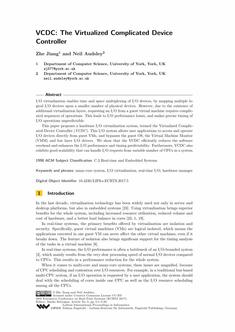
Figure 1 Flow of I/O Request in Traditional Virtualization System.
These issues are magnified with virtualization technology. When an application invokesan I/O request from a guest Virtual Machine (VM), this I/O request will be transmitted vialow layer drivers to the guest OS, Virtual Machine Monitor (VMM) and Host OS, whichresults in a serious loss of the system and I/O performance, see Figure 1.
In real-time systems, it is often vital for applications to access I/O devices at specifictimes in order to achieve the accurate control over I/O required. For example, the controlof an automotive engine often requires I/O at accurate times in order to inject fuel at theoptimal time [18]. Also, in a 3D printer, precise control of I/O is required [33]. This I/Ooperation must be occur at an exact time, i.e. be timing-accurate – it can be neither latenor early (within a small error bound). In a single-core system, latencies caused by devicedrivers and application process scheduling make timing-accurate I/O control problematic. Inmany-core systems, these issues are magnified: the transmission latencies from a processorto an I/O controller can be substantial and variable due to the communication bottlenecksand contention.
These issues are magnified even further with virtualization technology. Virtualizing onephysical I/O to multiple virtual I/Os, complex I/O resource management (e.g. schedulingand prioritization) and the complicated path of an I/O request worsen the transmissionlatencies from a processor to an I/O controller. Hence, it is difficult for an application froma guest VM to issue an I/O operation that will result in a timing-accurate device level I/Ooperation.
Virtualization relies on hardware support, therefore today’s chip manufacturers havepromoted different technologies for I/O virtualization in order to mitigate these issues. Intel’sVirtualization Technology for Directed I/O (VT-D) [12], which can provide a direct I/O accessfrom guest VMs, is one example of this. The IOMMU [2] is applied to commercial PC-basedsystems to offload memory protection and address translation, in order to provide a fast I/Oaccess from guest VMs. However, even with hardware assistance, the I/O performance fromthe guest VMs cannot reach the original I/O performance in a system without virtualization,let alone improve on it. Achieving timing accuracy of I/O operations in a virtualized system,even with hardware support is difficult [33]. Additionally, these commonly used hardwareassists on I/O virtualization cannot help the predictability and timing-accuracy of the I/Ooperations requested from guest VMs.
To overcome these issues, we designed a hardware I/O system for multi-core and many-core systems. The contribution of this paper is the designed virtualized complicated devicecontroller, termed the VCDC, that integrates the VMM and I/O drivers into the hardwarelayer, thus achieving significant improvements of I/O performance in guest VMs. The VMM
Z. Jiang and N. Audsley 5:3
in VCDC virtualizes a physical I/O device to multiple virtual I/O devices for guest VMs.For example, in a 16-core system, the VMM can separate a single monitor into 16 individualpartitions and provide access interfaces for each guest VM. In addition, the I/O driversin VCDC provide high layer control interfaces for the guest VMs. With VCDC, the userapplications in a guest VM are able to operate an I/O via very simple requests. Furthermore,if a user application is going to request the VGA controller to display a character from aguest VM, such as ‘A’, at coordinate (2, 1), the user application is only required to transferthe ASCII of the character followed by its coordinates to the VGA part inside VCDC, thatis ‘0x41’, ‘0x02’, ‘0x01’.
The VCDC utilises a timing-accurate I/O controller [32] to provide clock cycle levelaccurate I/O operations.
The paper is organized as follows: Section 2 presents our motivation. Section 3 presents thedesign and implementation of the VCDC, respectively. Section 4 evaluates the performanceof a many-core system with VCDC. Section 5 presents some related work, with conclusionsoffered in Section 6.
2 Motivation
The most significant challenge in I/O virtualization is the loss of I/O performance. Inconventional I/O virtualization, the potential overhead is associated with the indirection andinterposition of an I/O request, as well as the complex resource management (e.g. schedulingand prioritization) [25].
2.1 Complicated Path of I/O requestsFigure 1 shows the flow of I/O requests handled in a traditional virtualization system. Whenan application running within a VM issues an I/O request, typically by making a system call,it is initially processed by the I/O stack in the guest OS, which is also running within theVM. A device driver in the guest OS issues the request to a virtual I/O device, which theVMM then intercepts. The VMM schedules requests from multiple VMs onto an underlyingphysical I/O device, usually via another device driver managed by the VMM or a privilegedguest VM with direct access to the physical hardware.
This complicated path of I/O requests poses three main drawbacks for the whole sys-tem [25]:
Significant software overhead. Most of these operations are processed in software, whichcauses significant CPU overheads.Longer response time of I/O operations. Compared with the original system, virtualizationrequires more time to handle the same I/O request from the guest OS. This also causes adecline in I/O throughput.Worse timing accuracy of I/O Operations.. It is very difficult for an I/O operation(e.g. read) to occur at a particular time point [32].
2.2 Complicated I/O Resource ManagementIn multi-core and many-core systems, in addition to the complicated path of I/O requests,complex I/O resource management is another bottleneck in virtualization:
Single CPU (Multi-core) System (Figure 2a). In a bus-based single CPU system, userapplications can normally request and operate I/O devices by modifying memory-mappedregisters. The overhead of I/O resource management mainly comes from the scheduling of
ECRTS 2017
5:4 VCDC: The Virtualized Complicated Device Controller
CPU Memory
AXI_Lite
I/O
C
C
C
CPUMemory
Bus
I/O
C C
CPU
C
C
CPU
C
R
R
R
R
R
R
R
R
R
R
R
R
C C C
C C C
C CC
I/O
User Application
FreeRTOS I/O Manager
Kernel Mode
User Mode System Calls
TimerTimer
Hardware
Software
INTC
Memory
Bus
I/OC
CPU
C
(a) Single CPU system (multi-core)
C C
C C
CPU
Memory
Bus
I/O
C
C
C
CPUMemory
Bus
I/O
C C
CPU
C
C
CPU
C
(b) Multi-CPU System (multi-core)
CPU Memory
AXI_Lite
I/O
C
C
C
CPUMemory
Bus
I/O
C C
CPU
C
C
CPU
C
R
R
R
R
R
R
R
R
R
R
R
R
C C C
C C C
C CC
I/O
User Application
FreeRTOS I/O Manager
Kernel Mode
User Mode System Calls
TimerTimer
Hardware
Software
INTC
Memory
Bus
I/OC
CPU
C
(c) Many-core System
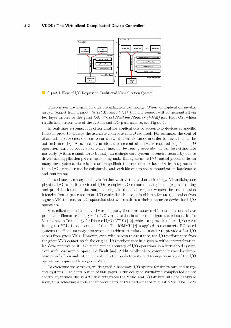
Figure 2 Structure of Multi-CPU and Many-Core Systems. C – Core; R – Router / Arbiter.
the CPU – deciding which core has the priority to access the I/O device. This procedureis normally handled by the OS.Multi-CPU System (Multi-core) (Figure 2b). In bus-based multi-CPU systems, apart fromthe CPU scheduling, the contention over I/O devices is unavoidable when a shared I/Ois to be accessed. To solve the issue of I/O contention among CPUs, hardware mutexesare normally added in multi-CPU systems, which causes extra hardware overhead as wellas high bus workload (frequent communication is required between CPUs and hardwaremutex).Many-core System (Figure 2c). In many-core systems, all arbitrations among cores areturned over to the system arbiter (e.g. the routers in a NoC-based system), therefore CPUscheduling is not required. However, many-core systems still suffer from I/O contentionwhen different cores need to access I/O devices at the same time.
In general, complicated I/O resource management poses the main three drawbacks forthe whole system:1. Significant system overhead. CPU scheduling is mostly implemented at the software
level, and I/O contention is mostly handled at the hardware level, which both consumesignificant system overhead.
2. Unpredictable I/O operations. The complexity of I/O management makes I/O operationsdifficult to predict.
3. Bad scalability. With the number of cores and CPUs increasing in a system, the workloadof resource management will be also increased, which causes more serious performancereduction of the whole system.
3 Virtualized Complicated Device Controller (VCDC)
Having presented the I/O problems suffered by virtualization technology in many-coreand multi-core real-time systems, in this section we proceed by introducing our proposedVirtualized Complicated Device Controller (VCDC), which enables:
Better I/O performance. Includes the lower response time of I/O operations and higherI/O throughput.Predictability. I/O operations requested from a guest OS are more predictable, thanunder conventional virtualization.Lower software overhead. Moves the VMM and low level I/O drivers from kernel mode(at the software level) to the VCDC.
Z. Jiang and N. Audsley 5:5
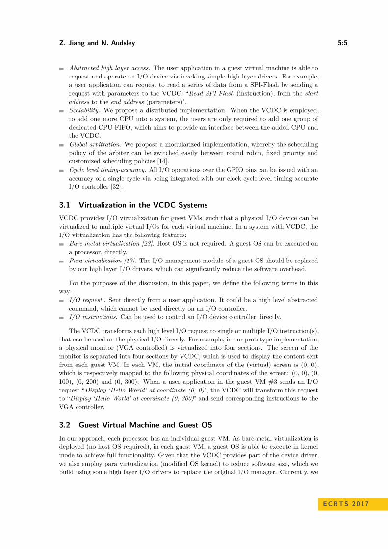
Abstracted high layer access. The user application in a guest virtual machine is able torequest and operate an I/O device via invoking simple high layer drivers. For example,a user application can request to read a series of data from a SPI-Flash by sending arequest with parameters to the VCDC: “Read SPI-Flash (instruction), from the startaddress to the end address (parameters)".Scalability. We propose a distributed implementation. When the VCDC is employed,to add one more CPU into a system, the users are only required to add one group ofdedicated CPU FIFO, which aims to provide an interface between the added CPU andthe VCDC.Global arbitration. We propose a modularized implementation, whereby the schedulingpolicy of the arbiter can be switched easily between round robin, fixed priority andcustomized scheduling policies [14].Cycle level timing-accuracy. All I/O operations over the GPIO pins can be issued with anaccuracy of a single cycle via being integrated with our clock cycle level timing-accurateI/O controller [32].
3.1 Virtualization in the VCDC SystemsVCDC provides I/O virtualization for guest VMs, such that a physical I/O device can bevirtualized to multiple virtual I/Os for each virtual machine. In a system with VCDC, theI/O virtualization has the following features:
Bare-metal virtualization [23]. Host OS is not required. A guest OS can be executed ona processor, directly.Para-virtualization [17]. The I/O management module of a guest OS should be replacedby our high layer I/O drivers, which can significantly reduce the software overhead.
For the purposes of the discussion, in this paper, we define the following terms in thisway:
I/O request.. Sent directly from a user application. It could be a high level abstractedcommand, which cannot be used directly on an I/O controller.I/O instructions. Can be used to control an I/O device controller directly.
The VCDC transforms each high level I/O request to single or multiple I/O instruction(s),that can be used on the physical I/O directly. For example, in our prototype implementation,a physical monitor (VGA controlled) is virtualized into four sections. The screen of themonitor is separated into four sections by VCDC, which is used to display the content sentfrom each guest VM. In each VM, the initial coordinate of the (virtual) screen is (0, 0),which is respectively mapped to the following physical coordinates of the screen: (0, 0), (0,100), (0, 200) and (0, 300). When a user application in the guest VM #3 sends an I/Orequest “Display ‘Hello World’ at coordinate (0, 0)", the VCDC will transform this requestto “Display ‘Hello World’ at coordinate (0, 300)" and send corresponding instructions to theVGA controller.
3.2 Guest Virtual Machine and Guest OSIn our approach, each processor has an individual guest VM. As bare-metal virtualization isdeployed (no host OS required), in each guest VM, a guest OS is able to execute in kernelmode to achieve full functionality. Given that the VCDC provides part of the device driver,we also employ para virtualization (modified OS kernel) to reduce software size, which webuild using some high layer I/O drivers to replace the original I/O manager. Currently, we
ECRTS 2017
5:6 VCDC: The Virtualized Complicated Device Controller
Application
Kernel ModeUser Mode
FreeRTOS
FreeRTOS I/O Manager
Low Layer I/O Driver
I/O
OS Kernel
Stan
dar
d F
ree
RTO
S A
PI(
)
Fre
eR
TOS_
Op
en
()
Fre
eR
TOS_
Wri
te()
Fre
eR
TOS_
Re
ad()
Fre
eR
TOS_
IOct
l()
Application
Kernel Mode
User Mode
FreeRTOS
Virtualized I/O
OS Kernel
High Layer I/O Driver
Stan
dar
d F
ree
RTO
S A
PI(
)
VC
DC
_Op
en
()
VC
DC
_Wri
te()
VC
DC
_Re
ad()
VC
DC
_IO
ctl(
)
Guest VM
Hardware
Hardware
CPUCPU
(a) FreeRTOS Kernel in a non-VCDC system)
Application
Kernel ModeUser Mode
FreeRTOS
FreeRTOS I/O Manager
Low Layer I/O Driver
I/O
OS Kernel
Stan
dar
d F
ree
RTO
S A
PI(
)
Fre
eR
TOS_
Op
en
()
Fre
eR
TOS_
Wri
te()
Fre
eR
TOS_
Re
ad()
Fre
eR
TOS_
IOct
l()
Application
Kernel Mode
User Mode
FreeRTOS
Virtualized I/O
OS Kernel
High Layer I/O Driver
Stan
dar
d F
ree
RTO
S A
PI(
)
VC
DC
_Op
en
()
VC
DC
_Wri
te()
VC
DC
_Re
ad()
VC
DC
_IO
ctl(
)
Guest VM
Hardware
Hardware
CPUCPU
(b) FreeRTOS Kernel in a VCDC system
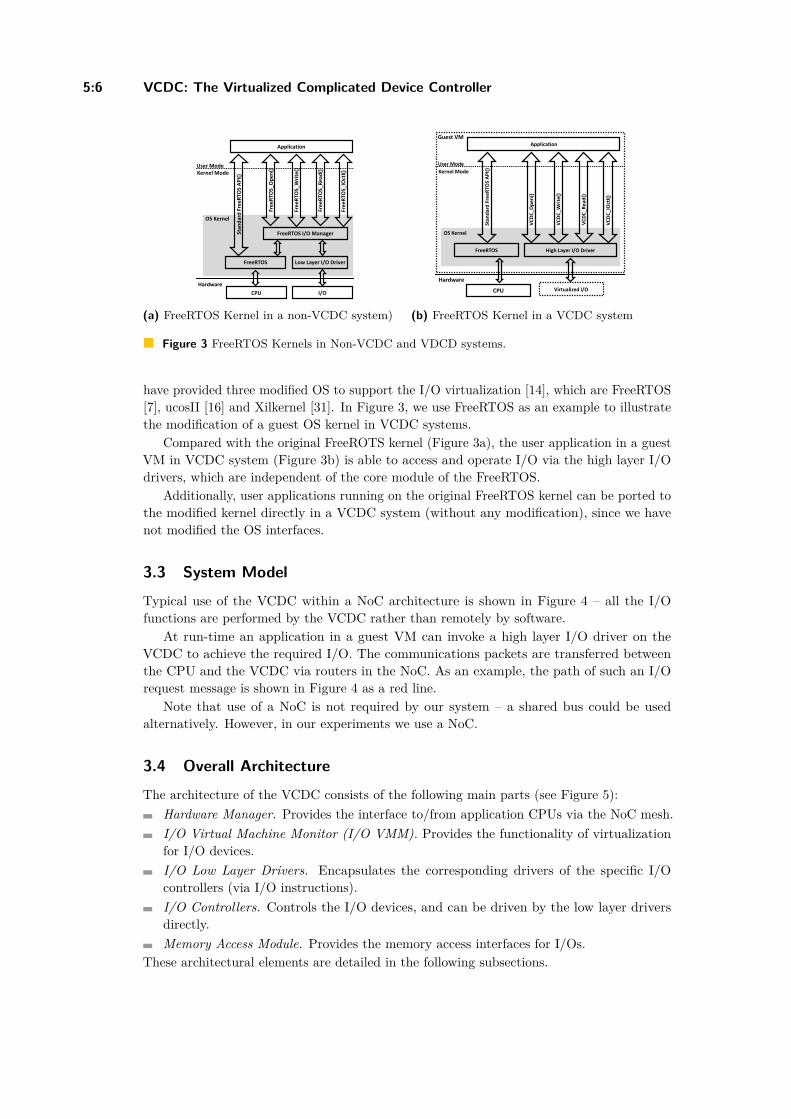
Figure 3 FreeRTOS Kernels in Non-VCDC and VDCD systems.
have provided three modified OS to support the I/O virtualization [14], which are FreeRTOS[7], ucosII [16] and Xilkernel [31]. In Figure 3, we use FreeRTOS as an example to illustratethe modification of a guest OS kernel in VCDC systems.
Compared with the original FreeROTS kernel (Figure 3a), the user application in a guestVM in VCDC system (Figure 3b) is able to access and operate I/O via the high layer I/Odrivers, which are independent of the core module of the FreeRTOS.
Additionally, user applications running on the original FreeRTOS kernel can be ported tothe modified kernel directly in a VCDC system (without any modification), since we havenot modified the OS interfaces.
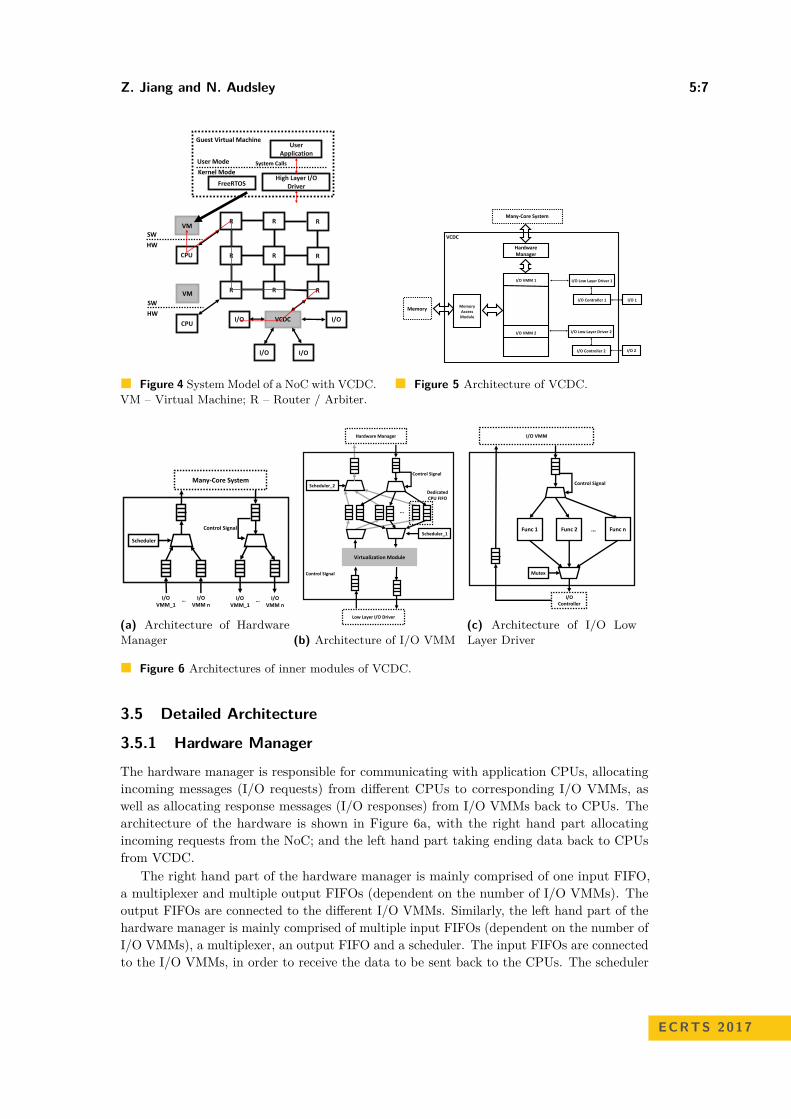
3.3 System Model
Typical use of the VCDC within a NoC architecture is shown in Figure 4 – all the I/Ofunctions are performed by the VCDC rather than remotely by software.
At run-time an application in a guest VM can invoke a high layer I/O driver on theVCDC to achieve the required I/O. The communications packets are transferred betweenthe CPU and the VCDC via routers in the NoC. As an example, the path of such an I/Orequest message is shown in Figure 4 as a red line.
Note that use of a NoC is not required by our system – a shared bus could be usedalternatively. However, in our experiments we use a NoC.
3.4 Overall Architecture
The architecture of the VCDC consists of the following main parts (see Figure 5):Hardware Manager. Provides the interface to/from application CPUs via the NoC mesh.I/O Virtual Machine Monitor (I/O VMM). Provides the functionality of virtualizationfor I/O devices.I/O Low Layer Drivers. Encapsulates the corresponding drivers of the specific I/Ocontrollers (via I/O instructions).I/O Controllers. Controls the I/O devices, and can be driven by the low layer driversdirectly.Memory Access Module. Provides the memory access interfaces for I/Os.
These architectural elements are detailed in the following subsections.
Z. Jiang and N. Audsley 5:7
OS Kernel
I/O #1
VM 1 VM 2 VM n…
VCDC
Virtual I/O #1
Virtual I/O #1
Virtual I/O #1
Software
Hardware
VCDCI/O
CPU
I/O
I/O I/O
SW
HW
R
R
R
R
R
R
R
R
R
VM
CPU
SW
HW
VM
User Application
FreeRTOSHigh Layer I/O
Driver
Guest Virtual Machine
Kernel Mode
User Mode System Calls
Figure 4 System Model of a NoC with VCDC.VM – Virtual Machine; R – Router / Arbiter.
VCDC
Memory
I/O Controller 1
I/O Low Layer Driver 1
I/O Controller 2
I/O Low Layer Driver 2
I/O 1
I/O 2
I/O VMM 1
I/O VMM 2
MemoryAccess
Module
I/O
VM
M_1
I/O
VM
M_2
I/O
VM
M_3
I/O
VM
M_0
…..
Hardware Manager
Many-Core System
Figure 5 Architecture of VCDC.
Control Signal
Child I/O
VMM 1
Child I/O
VMM 2
Child I/O
VMM n…
BlueGrass
Scheduler
InstructionTranslation
Module
Lib: ANSI Escape Code
InstructionDe-
TranslationModule
Receive UART instruction from VM #A to print a string S
Get the virtual coordinate (Xv, Yv) of the cursor in the virtual
console of VM #A
Convert the virtual coordinate to the physical coordinate (Xp,
Yp) of the console
Use the ANSI Escape Code to move the cursor to (Xp, Yp) of
the console
Print the string S
Child I/O VMM n
I/O Driver 1 I/O Driver 2 I/O Driver n
I/O VMM n
Control Signal
Scheduler
I/O VMM_1
Many-Core SystemMemory Access
Module
VMMI/O
Controllers
Memory Write
Memory Read
Memory Access: BlueTree
… I/O VMM n
I/O VMM_1
…
(a) Architecture of HardwareManager
…
Virtualization Module
Dedicated CPU FIFO
Scheduler_1
Scheduler_2
Low Layer I/O Driver
Hardware Manager
Control Signal
Control Signal
(b) Architecture of I/O VMM
Control Signal
Func 1 Func 2 Func n…
I/O VMM
I/O Controller
Mutex
(c) Architecture of I/O LowLayer Driver
Figure 6 Architectures of inner modules of VCDC.
3.5 Detailed Architecture
3.5.1 Hardware Manager
The hardware manager is responsible for communicating with application CPUs, allocatingincoming messages (I/O requests) from different CPUs to corresponding I/O VMMs, aswell as allocating response messages (I/O responses) from I/O VMMs back to CPUs. Thearchitecture of the hardware is shown in Figure 6a, with the right hand part allocatingincoming requests from the NoC; and the left hand part taking ending data back to CPUsfrom VCDC.
The right hand part of the hardware manager is mainly comprised of one input FIFO,a multiplexer and multiple output FIFOs (dependent on the number of I/O VMMs). Theoutput FIFOs are connected to the different I/O VMMs. Similarly, the left hand part of thehardware manager is mainly comprised of multiple input FIFOs (dependent on the number ofI/O VMMs), a multiplexer, an output FIFO and a scheduler. The input FIFOs are connectedto the I/O VMMs, in order to receive the data to be sent back to the CPUs. The scheduler
ECRTS 2017
5:8 VCDC: The Virtualized Complicated Device Controller
controls the multiplexer to choose which input FIFO can transmit data into the output FIFO(if neither input FIFO is empty the FIFOs are chosen in a round-robin manner).
Additionally, the FIFOs used to connect with I/O VMMs can be connected to I/Ocontrollers directly, which assists in supporting different I/O devices.
3.5.2 I/O VMM
I/O VMM maintains the virtualization of I/O devices. Considering that the functionalitiesand features of I/O devices are different, it is very difficult to build a general-purposemodule to achieve virtualization for all kinds of I/O devices. Therefore, we create somespecific-purpose I/O VMM for those commonly used I/O devices, including UART, VGA,DMA, Ethernet, etc. Users can also easily add their customized I/O VMM into VCDCvia our provided interfaces [14]. All of these I/O VMMs have a general architecture, seeFigure 6b.
The general architecture of the I/O VMMs are the same, except for the virtualization mod-ule. The I/O VMM is comprised of two groups of communication FIFOs, four multiplexers,two schedulers, groups of dedicated CPU FIFOs and a virtualization module.
The two groups of communication FIFOs are connected with the hardware manager anda low layer I/O driver respectively, providing the communication interfaces between thehardware manager and the low layer I/O drivers. The dedicated CPU FIFOs are built to storethe I/O requests sent from different CPUs and I/O response messages sent back from the I/O(as buffers); one CPU owns an individual group of dedicated CPU FIFOs. The number ofgroups of dedicated FIFOs are generic, so that users can add any number of dedicated CPUFIFOs into the VCDC [14], which provides for scalability. The two schedulers take charge ofthe scheduling of I/O requests and I/O response. Specifically, Scheduler_1 determines whichI/O request can be served by the virtualization module first, and Scheduler_2 determineswhich I/O response can be sent back to the hardware manager first.
The virtualization module transforms I/O requests (sent to an virtual I/O) to I/Oinstructions (can be used to control a physical I/O). The implementation of this virtualizationmodule depends on the specific I/O devices to be controlled. Currently, we have providedthe virtualization module for some commonly used I/O, including UART, VGA, DMA,Ethernet and an SPI NOR-flash. Due to limitations of space here, in Section 4.3.1 we willonly introduce the virtualization module for the Ethernet as an example.
3.5.3 Low Layer I/O Driver
Low layer I/O drivers takes charge of encapsulating the specific I/O drivers for an specific I/Ocontroller (shown in Figure 6c). We encapsulate the functions of I/O drivers into separatehardware modules, e.g. read the data from a specific address of the SPI NOR-flash.
As shown, a low layer I/O driver is comprised of two FIFOs (one input and one output),two multiplexers, one mutex and multiple functions of I/O drivers. Specifically, the inputFIFO is responsible for receiving I/O instructions from I/O VMM, and the output FIFOtakes charge of receiving I/O responses from the I/O controller. In order to guarantee thatthe low layer I/O driver is able to execute the I/O instructions in the same sequence as theyare sent by the I/O VMM, a mutex is added. While instructions are being carried out byone of the hardware functions, other I/O instructions must be blocked to wait to access theI/O controller.
Z. Jiang and N. Audsley 5:9
3.5.4 Memory Access ModuleVCDC also provides an interface to access the external memory (DDR), which is namedBlueTree [11]. I/O devices are able to use this interface to read and write the externalmemory, such as the DMA. We will not introduce the implementation of the memory accessmodule in this paper; for more details please see [11], [9] and [10].
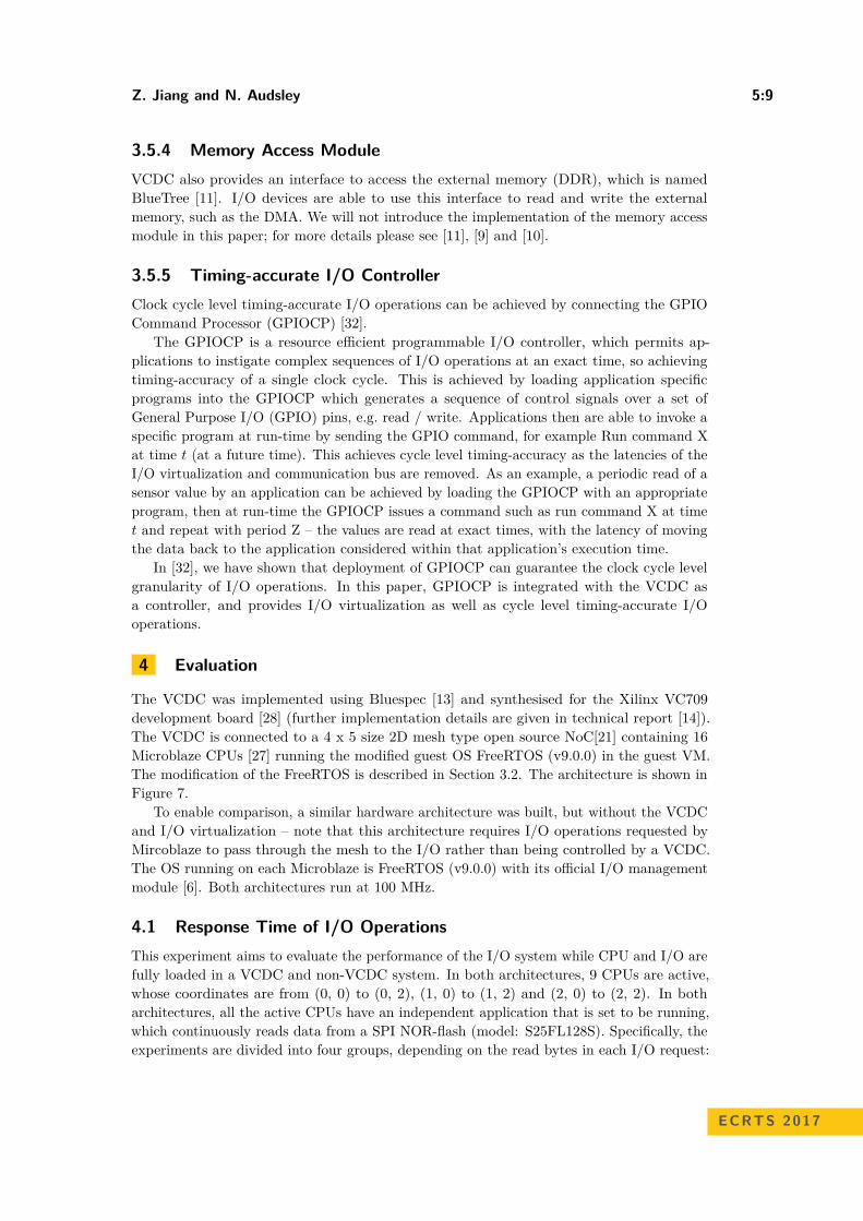
3.5.5 Timing-accurate I/O ControllerClock cycle level timing-accurate I/O operations can be achieved by connecting the GPIOCommand Processor (GPIOCP) [32].
The GPIOCP is a resource efficient programmable I/O controller, which permits ap-plications to instigate complex sequences of I/O operations at an exact time, so achievingtiming-accuracy of a single clock cycle. This is achieved by loading application specificprograms into the GPIOCP which generates a sequence of control signals over a set ofGeneral Purpose I/O (GPIO) pins, e.g. read / write. Applications then are able to invoke aspecific program at run-time by sending the GPIO command, for example Run command Xat time t (at a future time). This achieves cycle level timing-accuracy as the latencies of theI/O virtualization and communication bus are removed. As an example, a periodic read of asensor value by an application can be achieved by loading the GPIOCP with an appropriateprogram, then at run-time the GPIOCP issues a command such as run command X at timet and repeat with period Z – the values are read at exact times, with the latency of movingthe data back to the application considered within that application’s execution time.
In [32], we have shown that deployment of GPIOCP can guarantee the clock cycle levelgranularity of I/O operations. In this paper, GPIOCP is integrated with the VCDC asa controller, and provides I/O virtualization as well as cycle level timing-accurate I/Ooperations.
4 Evaluation
The VCDC was implemented using Bluespec [13] and synthesised for the Xilinx VC709development board [28] (further implementation details are given in technical report [14]).The VCDC is connected to a 4 x 5 size 2D mesh type open source NoC[21] containing 16Microblaze CPUs [27] running the modified guest OS FreeRTOS (v9.0.0) in the guest VM.The modification of the FreeRTOS is described in Section 3.2. The architecture is shown inFigure 7.
To enable comparison, a similar hardware architecture was built, but without the VCDCand I/O virtualization – note that this architecture requires I/O operations requested byMircoblaze to pass through the mesh to the I/O rather than being controlled by a VCDC.The OS running on each Microblaze is FreeRTOS (v9.0.0) with its official I/O managementmodule [6]. Both architectures run at 100 MHz.
4.1 Response Time of I/O OperationsThis experiment aims to evaluate the performance of the I/O system while CPU and I/O arefully loaded in a VCDC and non-VCDC system. In both architectures, 9 CPUs are active,whose coordinates are from (0, 0) to (0, 2), (1, 0) to (1, 2) and (2, 0) to (2, 2). In botharchitectures, all the active CPUs have an independent application that is set to be running,which continuously reads data from a SPI NOR-flash (model: S25FL128S). Specifically, theexperiments are divided into four groups, depending on the read bytes in each I/O request:
ECRTS 2017
5:10 VCDC: The Virtualized Complicated Device Controller
R
R
R
R
R
R
M
M
(0, 0)
(0, 1)
VCDC
SW
HW
VM
SW
HW
VM
M
SW
HW
VM
M
SW
HW
VM
I/O I/O T
R
R
R
R
R
R
M
M
SW
HW
VM
SW
HW
VM
M
SW
HW
VM
M
SW
HW
VM
RR
M
SW
HW
VM
RR
M
SW
HW
VM
M
SW
HW
VM
M
SW
HW
VM
M
SW
HW
VM
M
SW
HW
VM
M
SW
HW
VM
M
SW
HW
VM
RR RR
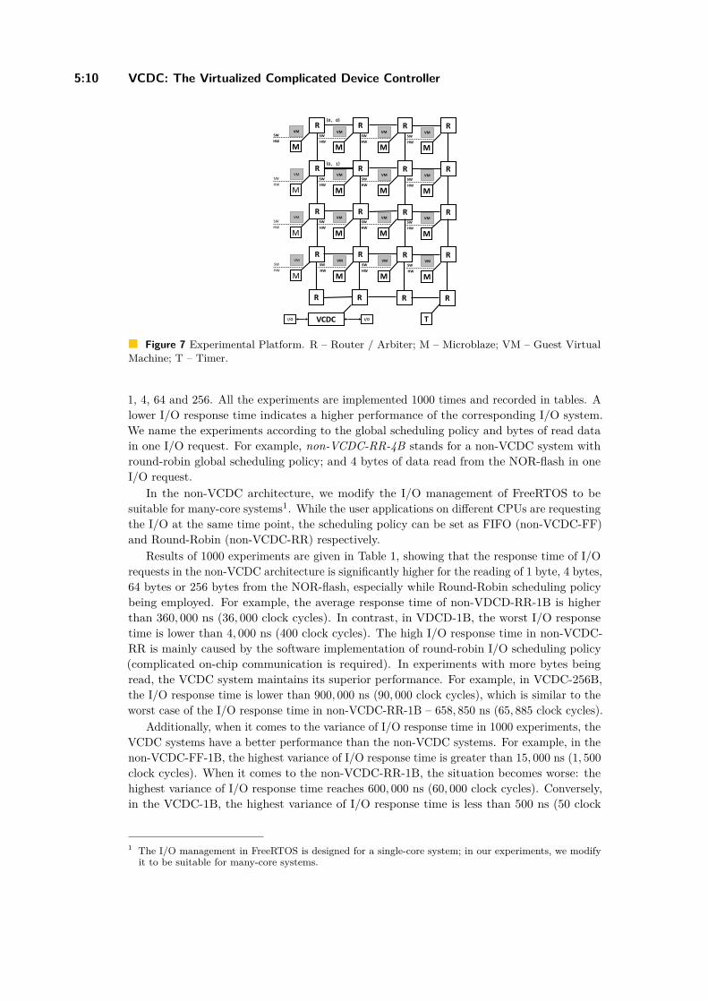
Figure 7 Experimental Platform. R – Router / Arbiter; M – Microblaze; VM – Guest VirtualMachine; T – Timer.
1, 4, 64 and 256. All the experiments are implemented 1000 times and recorded in tables. Alower I/O response time indicates a higher performance of the corresponding I/O system.We name the experiments according to the global scheduling policy and bytes of read datain one I/O request. For example, non-VCDC-RR-4B stands for a non-VCDC system withround-robin global scheduling policy; and 4 bytes of data read from the NOR-flash in oneI/O request.
In the non-VCDC architecture, we modify the I/O management of FreeRTOS to besuitable for many-core systems1. While the user applications on different CPUs are requestingthe I/O at the same time point, the scheduling policy can be set as FIFO (non-VCDC-FF)and Round-Robin (non-VCDC-RR) respectively.
Results of 1000 experiments are given in Table 1, showing that the response time of I/Orequests in the non-VCDC architecture is significantly higher for the reading of 1 byte, 4 bytes,64 bytes or 256 bytes from the NOR-flash, especially while Round-Robin scheduling policybeing employed. For example, the average response time of non-VDCD-RR-1B is higherthan 360, 000 ns (36, 000 clock cycles). In contrast, in VDCD-1B, the worst I/O responsetime is lower than 4, 000 ns (400 clock cycles). The high I/O response time in non-VCDC-RR is mainly caused by the software implementation of round-robin I/O scheduling policy(complicated on-chip communication is required). In experiments with more bytes beingread, the VCDC system maintains its superior performance. For example, in VCDC-256B,the I/O response time is lower than 900, 000 ns (90, 000 clock cycles), which is similar to theworst case of the I/O response time in non-VCDC-RR-1B – 658, 850 ns (65, 885 clock cycles).
Additionally, when it comes to the variance of I/O response time in 1000 experiments, theVCDC systems have a better performance than the non-VCDC systems. For example, in thenon-VCDC-FF-1B, the highest variance of I/O response time is greater than 15, 000 ns (1, 500clock cycles). When it comes to the non-VCDC-RR-1B, the situation becomes worse: thehighest variance of I/O response time reaches 600, 000 ns (60, 000 clock cycles). Conversely,in the VCDC-1B, the highest variance of I/O response time is less than 500 ns (50 clock
1 The I/O management in FreeRTOS is designed for a single-core system; in our experiments, we modifyit to be suitable for many-core systems.

Z. Jiang and N. Audsley 5:11
Table 1 I/O response time in VCDC and non-VCDC systems (unit: clock cycle).
Non-VCDC SystemScheduling Policy: FIFO
Non-VCDC SystemScheduling Policy: RoundRobin VCDC System
CPU Index Min Max Mean Min Max Mean Min Max MeanRead 1 Byte
(0, 0) 9357 9357 9357 6149 65885 36060 285 285 285(0, 1) 7425 8989 8915 7073 65849 35860 380 403 396(0, 2) 7057 8598 8415 7096 65849 36049 380 403 395(1, 0) 7057 8207 8203 7096 65826 36237 357 403 391(1, 1) 9748 9748 9748 7073 65826 36410 403 403 403(1, 2) 7425 8966 7476 7073 65826 36576 334 334 334(2, 0) 7034 8598 7467 7073 65826 36741 357 403 366(2, 1) 7057 8207 7576 7096 65826 36930 357 403 377(2, 2) 6121 6121 6121 7073 65803 37102 334 334 334
Read 4 Bytes(0, 0) 58002 58477 58021 29515 316248 173091 1066 1123 1093(0, 1) 29611 36281 34908 33243 309490 168542 1247 1408 1356(0, 2) 29657 37017 36191 34770 322660 176642 1293 1569 1398(1, 0) 28875 36258 35264 34770 322547 177561 1362 1569 1412(1, 1) 58361 58844 58381 33243 309382 171130 1316 1385 1325(1, 2) 29588 35499 30208 34657 322547 179222 1247 1408 1270(2, 0) 29979 37040 31290 35223 327813 182972 1247 1569 1322(2, 1) 28139 36235 34785 32641 302799 169881 1293 1431 1369(2, 2) 57579 58062 57599 32535 302693 170670 1247 1270 1249
Read 64 Bytes(0, 0) 907744 929955 918905 408908 4381352 2398035 18770 19245 18935(0, 1) 450935 478696 460279 393536 4216640 2307883 19007 20272 19521(0, 2) 479501 579758 538170 476993 4426369 2423243 19053 22549 20808(1, 0) 473268 571294 520525 476993 4424823 2435851 19145 23032 21203(1, 1) 909739 936166 921822 488037 4541994 2512343 19076 19398 19188(1, 2) 449348 473636 456782 475305 4423507 2446804 19007 20157 19418(2, 0) 474027 579068 535487 475305 4423507 2469029 19007 22043 20535(2, 1) 472095 565429 518137 489451 4555159 2542512 19007 22549 20895(2, 2) 900332 920618 907492 468232 4356158 2456170 19007 19237 19073
Read 256 Bytes(0 ,0) 3628902 3702565 3674076 1586442 16998330 9303655 75609 78231 76046(0, 1) 1810819 1897023 1826232 1848174 17206343 9370227 75839 79841 77648(0, 2) 1897828 2181970 2119170 1830492 17041721 9280577 75885 88305 83101(1, 0) 1890399 2132060 2046512 1862700 17279325 9512215 75997 89708 84212(1, 1) 3631085 3708365 3679649 1848508 17147673 9620444 75908 78484 76336(1, 2) 1808220 1897000 1823103 1842516 17147673 9528055 75839 79542 77494(2, 0) 1897391 2180659 2116159 1828370 17016021 9497681 75839 87040 82616(2, 1) 1890422 2131301 2044241 1869796 17345151 9731236 75839 89202 83631(2, 2) 3616296 3682191 3641053 1826248 16990334 9579806 75839 78346 76212
ECRTS 2017
5:12 VCDC: The Virtualized Complicated Device Controller
cpu (0,0) cpu (0,1) cpu (0,2) cpu (0,3)0
200
400
600
800
1000
1200
1400
1600
Thr
ough
put (
Uni
t: K
B/s
)
Non-VCDC; Scheduling Policy: FIFONon-VCDC; Scheduling Policy: RoundRobinVCDC; Scheduling Policy: RoundRobin
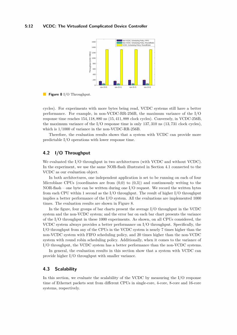
Figure 8 I/O Throughput.
cycles). For experiments with more bytes being read, VCDC systems still have a betterperformance. For example, in non-VCDC-RR-256B, the maximum variance of the I/Oresponse time reaches 154, 118, 880 ns (15, 411, 888 clock cycles). Conversely, in VCDC-256B,the maximum variance of the I/O response time is only 137, 310 ns (13, 731 clock cycles),which is 1/1000 of variance in the non-VCDC-RR-256B.
Therefore, the evaluation results shows that a system with VCDC can provide morepredictable I/O operations with lower response time.
4.2 I/O Throughput
We evaluated the I/O throughput in two architectures (with VCDC and without VCDC).In the experiment, we use the same NOR-flash illustrated in Section 4.1 connected to theVCDC as our evaluation object.
In both architectures, one independent application is set to be running on each of fourMicroblaze CPUs (coordinates are from (0,0) to (0,3)) and continuously writing to theNOR-flash – one byte can be written during one I/O request. We record the written bytesfrom each CPU within 1 second as the I/O throughput. The result of higher I/O throughputimplies a better performance of the I/O system. All the evaluations are implemented 1000times. The evaluation results are shown in Figure 8.
In the figure, four groups of bar charts present the average I/O throughput in the VCDCsystem and the non-VCDC system; and the error bar on each bar chart presents the varianceof the I/O throughput in these 1000 experiments. As shown, on all CPUs considered, theVCDC system always provides a better performance on I/O throughput. Specifically, theI/O throughput from any of the CPUs in the VCDC system is nearly 7 times higher than thenon-VCDC system with FIFO scheduling policy, and 20 times higher than the non-VCDCsystem with round robin scheduling policy. Additionally, when it comes to the variance ofI/O throughput, the VCDC system has a better performance than the non-VCDC systems.
In general, the evaluation results in this section show that a system with VCDC canprovide higher I/O throughput with smaller variance.
4.3 Scalability
In this section, we evaluate the scalability of the VCDC by measuring the I/O responsetime of Ethernet packets sent from different CPUs in single-core, 4-core, 8-core and 16-coresystems, respectively.
Z. Jiang and N. Audsley 5:13
Ethernet Virtualization Module
VCDC
1G/2.5G Ethernet subsystem
TEMAC
GMII
AXI Ethernet Buffer
AXI StreamI/O control pins
AXI Lite AXI Stream
PHY
I/O VMM
Sending to the Ethernet Buffer
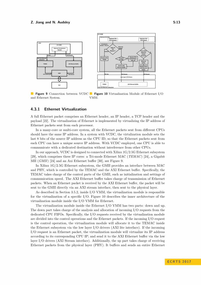
Figure 9 Connection between VCDCand Ethernet System.
If source IP Addr
(Source IP & 0xFFFFFF00) |
CPU_ID
Y
N
Send to AXI Ethernet Buffer
Dedicate CPU FIFO (output)
Types of I/O
Request ?
Send to the TEMAC
Control
AXI Lite
Ethernet Packet
AXI Stream
AXI Ethernet Buffer
Receive from AXI Ethernet
Buffer
AXI Stream
Ethernet Buffer
Dedicate CPU FIFO (input)
N
Virtualization Module - Ethernet
Dedicated CPU FIFOs
TEMAC
I/O VMM
Low Layer I/O Drivers
1G/2.5G Ethernet subsystem
If an entire Ethernet Packet
Received
Y
Figure 10 Virtualization Module of Ethernet I/OVMM.
4.3.1 Ethernet Virtualization
A full Ethernet packet comprises an Ethernet header, an IP header, a TCP header and thepayload [22]. The virtualization of Ethernet is implemented by virtualizing the IP address ofEthernet packets sent from each processor.
In a many-core or multi-core system, all the Ethernet packets sent from different CPUsshould have the same IP address. In a system with VCDC, the virtulization module sets thelast 8 bits of the source IP address as the CPU ID, so that the Ethernet packets sent fromeach CPU can have a unique source IP address. With VCDC employed, one CPU is able tocommunicate with a dedicated destination without interference from other CPUs.
In our approach, VCDC is designed to connected with Xilinx 1G/2.5G Ethernet subsystem[29], which comprises three IP cores: a Tri-mode Ethernet MAC (TEMAC ) [24], a GigabitMII (GMII ) [24] and an Axi Ethernet buffer [30], see Figure 9.
In Xilinx 1G/2.5G Ethernet subsystem, the GMII provides an interface between MACand PHY, which is controlled by the TEMAC and the AXI Ethernet buffer. Specifically, theTEMAC takes charge of the control parts of the GMII, such as initialization and settings ofcommunication speed. The AXI Ethernet buffer takes charge of transmission of Ethernetpackets. When an Ethernet packet is received by the AXI Ethernet buffer, the packet will besent to the GMII directly via an AXI stream interface, then sent to the physical layer.
As described in Section 3.5.2, inside I/O VMM, the virtualization module is responsiblefor the virtualization of a specific I/O. Figure 10 describes the inner architecture of thevirtualization module inside the I/O VMM for Ethernet.
The virtualization module inside the Ethernet I/O VMM has two parts: down and up.The down part takes charge of the analysis and allocation of incoming I/O requests from thededicated CPU FIFOs. Specifically, the I/O requests received by the virtualization moduleare divided into the control operations and the Ethernet packets. If the incoming I/O requestis the control operation, the virtualization module will allocate it to the TEMAC insidethe Ethernet subsystem via the low layer I/O drivers (AXI lite interface). If the incomingI/O request is an Ethernet packet, the virtualization module will virtualize its IP addressaccording to its corresponding CPU IP; and send it to the AXI Ethernet buffer via the lowlayer I/O drivers (AXI Stream interface). Additionally, the up part takes charge of receivingEthernet packets from the physical layer (PHY). It buffers and sends an entire Ethernet
ECRTS 2017
5:14 VCDC: The Virtualized Complicated Device Controller
packet back to the corresponding dedicated CPU FIFO according to the destination IPaddress of this Ethernet packet.
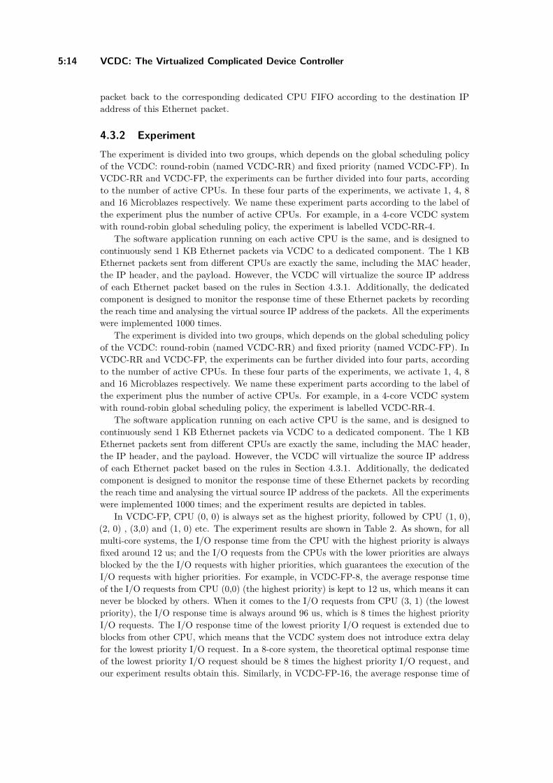
4.3.2 ExperimentThe experiment is divided into two groups, which depends on the global scheduling policyof the VCDC: round-robin (named VCDC-RR) and fixed priority (named VCDC-FP). InVCDC-RR and VCDC-FP, the experiments can be further divided into four parts, accordingto the number of active CPUs. In these four parts of the experiments, we activate 1, 4, 8and 16 Microblazes respectively. We name these experiment parts according to the label ofthe experiment plus the number of active CPUs. For example, in a 4-core VCDC systemwith round-robin global scheduling policy, the experiment is labelled VCDC-RR-4.
The software application running on each active CPU is the same, and is designed tocontinuously send 1 KB Ethernet packets via VCDC to a dedicated component. The 1 KBEthernet packets sent from different CPUs are exactly the same, including the MAC header,the IP header, and the payload. However, the VCDC will virtualize the source IP addressof each Ethernet packet based on the rules in Section 4.3.1. Additionally, the dedicatedcomponent is designed to monitor the response time of these Ethernet packets by recordingthe reach time and analysing the virtual source IP address of the packets. All the experimentswere implemented 1000 times.
The experiment is divided into two groups, which depends on the global scheduling policyof the VCDC: round-robin (named VCDC-RR) and fixed priority (named VCDC-FP). InVCDC-RR and VCDC-FP, the experiments can be further divided into four parts, accordingto the number of active CPUs. In these four parts of the experiments, we activate 1, 4, 8and 16 Microblazes respectively. We name these experiment parts according to the label ofthe experiment plus the number of active CPUs. For example, in a 4-core VCDC systemwith round-robin global scheduling policy, the experiment is labelled VCDC-RR-4.
The software application running on each active CPU is the same, and is designed tocontinuously send 1 KB Ethernet packets via VCDC to a dedicated component. The 1 KBEthernet packets sent from different CPUs are exactly the same, including the MAC header,the IP header, and the payload. However, the VCDC will virtualize the source IP addressof each Ethernet packet based on the rules in Section 4.3.1. Additionally, the dedicatedcomponent is designed to monitor the response time of these Ethernet packets by recordingthe reach time and analysing the virtual source IP address of the packets. All the experimentswere implemented 1000 times; and the experiment results are depicted in tables.
In VCDC-FP, CPU (0, 0) is always set as the highest priority, followed by CPU (1, 0),(2, 0) , (3,0) and (1, 0) etc. The experiment results are shown in Table 2. As shown, for allmulti-core systems, the I/O response time from the CPU with the highest priority is alwaysfixed around 12 us; and the I/O requests from the CPUs with the lower priorities are alwaysblocked by the the I/O requests with higher priorities, which guarantees the execution of theI/O requests with higher priorities. For example, in VCDC-FP-8, the average response timeof the I/O requests from CPU (0,0) (the highest priority) is kept to 12 us, which means it cannever be blocked by others. When it comes to the I/O requests from CPU (3, 1) (the lowestpriority), the I/O response time is always around 96 us, which is 8 times the highest priorityI/O requests. The I/O response time of the lowest priority I/O request is extended due toblocks from other CPU, which means that the VCDC system does not introduce extra delayfor the lowest priority I/O request. In a 8-core system, the theoretical optimal response timeof the lowest priority I/O request should be 8 times the highest priority I/O request, andour experiment results obtain this. Similarly, in VCDC-FP-16, the average response time of

Z. Jiang and N. Audsley 5:15
Table 2 Average Response Time of Loop Back 1KB Ethernet Packets in VCDC System (GlobalScheduling Policy: Fixed Priority; Unit: us).
Number of CPUsCPU Index 1 2 3 4
(0, 0) 12.09 12.07 12.09 12.08(1, 0) – 25.50 25.51 25.50(2, 0) – 36.92 36.94 36.93(3, 0) – 48.35 48.36 48.35(0, 1) – – 59.78 59.78(1, 1) – – 71.21 71.19(2, 1) – – 82.62 82.62(3, 1) – – 94.06 95.06(0, 2) – – – 105.46(1, 2) – – – 116.90(2, 2) – – – 128.31(3, 2) – – – 139.74(0, 3) – – – 151.17(1, 3) – – – 162.58(2, 3) – – – 174.02(3, 3) – – – 185.44
Table 3 Average Response Time of Loop Back 1KB Ethernet Packets in VCDC System (GlobalScheduling Policy: Round Robin; Unit: us).
Number of CPUsCPU Index 1 2 3 4
(0, 0) 12.32 46.71 90.58 180.15(1, 0) – 47.20 90.88 180.71(2, 0) – 47.68 91.22 179.99(3, 0) – 48.19 91.58 180.66(0, 1) – – 91.93 180.04(1, 1) – – 92.27 180.71(2, 1) – – 92.63 180.09(3, 1) – – 92.98 180.77(0, 2) – – – 180.04(1, 2) – – – 180.71(2, 2) – – – 180.09(3, 2) – – – 180.77(0, 3) – – – 180.04(1, 3) – – – 180.71(2, 3) – – – 180.09(3, 3) – – – 180.77
the I/O request from CPU (3,3) (the lowest priority) is around 190 us, which is 16 timesthe response time of the highest priority I/O requests. The results still meet the theoreticaloptimal value. These experiments indicate a good scalability of the VCDC.
In VCDC-RR, the global arbiter is set to start from operating a random I/O requestin each independent experiment. The experiment results are shown in Table 3. As shown,with an increase in the number of CPUs, the I/O response time of each CPU is proportionalto the number of CPUs. Specifically, compared to the response time of an I/O request inVCDC-RR-1, the average I/O response time of an I/O request in VCDC-RR-4, VCDC-RR-4and VCDC-RR-16 is respectively around 4, 8 and 16 times the average I/O response time ina single-core system. These results are close to the theoretical optimal values, which shows agood scalability of the VCDC.
4.4 Hardware and Software Overhead
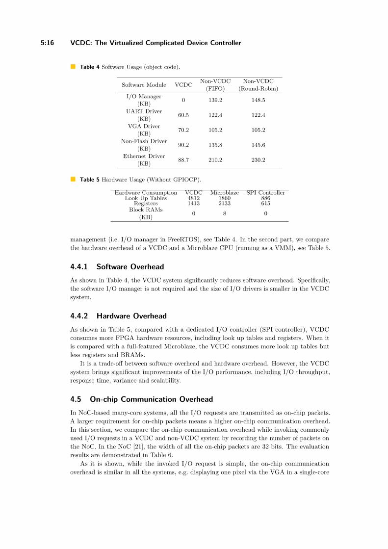
This section can be mainly divided into two parts. In the first part, we compare the softwareoverhead of a VCDC system and non-VCDC system with a software implementation of I/O
ECRTS 2017
5:16 VCDC: The Virtualized Complicated Device Controller
Table 4 Software Usage (object code).
Software Module VCDC Non-VCDC(FIFO)
Non-VCDC(Round-Robin)
I/O Manager(KB) 0 139.2 148.5
UART Driver(KB) 60.5 122.4 122.4
VGA Driver(KB) 70.2 105.2 105.2
Non-Flash Driver(KB) 90.2 135.8 145.6
Ethernet Driver(KB) 88.7 210.2 230.2
Table 5 Hardware Usage (Without GPIOCP).
Hardware Consumption VCDC Microblaze SPI ControllerLook Up Tables 4812 1860 886
Registers 1413 2133 615Block RAMs
(KB) 0 8 0
management (i.e. I/O manager in FreeRTOS), see Table 4. In the second part, we comparethe hardware overhead of a VCDC and a Microblaze CPU (running as a VMM), see Table 5.
4.4.1 Software OverheadAs shown in Table 4, the VCDC system significantly reduces software overhead. Specifically,the software I/O manager is not required and the size of I/O drivers is smaller in the VCDCsystem.
4.4.2 Hardware OverheadAs shown in Table 5, compared with a dedicated I/O controller (SPI controller), VCDCconsumes more FPGA hardware resources, including look up tables and registers. When itis compared with a full-featured Microblaze, the VCDC consumes more look up tables butless registers and BRAMs.
It is a trade-off between software overhead and hardware overhead. However, the VCDCsystem brings significant improvements of the I/O performance, including I/O throughput,response time, variance and scalability.
4.5 On-chip Communication OverheadIn NoC-based many-core systems, all the I/O requests are transmitted as on-chip packets.A larger requirement for on-chip packets means a higher on-chip communication overhead.In this section, we compare the on-chip communication overhead while invoking commonlyused I/O requests in a VCDC and non-VCDC system by recording the number of packets onthe NoC. In the NoC [21], the width of all the on-chip packets are 32 bits. The evaluationresults are demonstrated in Table 6.
As it is shown, while the invoked I/O request is simple, the on-chip communicationoverhead is similar in all the systems, e.g. displaying one pixel via the VGA in a single-core

Z. Jiang and N. Audsley 5:17
Table 6 On-chip Communication Overhead.
I/O Device I/O OperationNumber of on-chip Packets
(Each Packet: 32-bit)Non-VCDC
FIFONon-VCDCRound-Robin VCDC
VGADisplay 1 Pixel
1 CPU 6 6 34 CPUs 24 33 1210 CPUs 60 87 30
Display 10 Pixels1 CPU 60 60 304 CPUs 240 357 12010 CPUs 600 897 300
SPI FlashRead 1 Byte
1 CPU 12 12 44 CPUs 48 57 1610 CPUs 120 237 40
Read 10 Bytes1 CPU 120 120 404 CPUs 480 597 16010 CPUs 1200 1497 400
system. When the I/O operations become complicated or the number of CPUs are increased,the on-chip communication overhead in non-VCDC architecture is significant; in contrast,the VCDC architecture has a lower on-chip communication overhead, for example, reading10 bytes data from the SPI flash in 10-core systems.
4.5.1 Bottleneck of On-chip CommunicationIn the proposed design, a single channel interface is used for transmitting VCDC requests. Itconnects the many-core system and the VCDC, which has been explained in Section 3.5.1.Frequently invoked VCDC requests might cause traffic congestion at the entrance of theVCDC, which decreases the predictability of I/O operations. This traffic congestions canfurther affect the communication issues on the system level.
4.5.2 DiscussionIn current stage, a provided solution is adding the number of communication channels in theinterface between many-core system and VCDC. The multiple communication channels canalleviate communication traffic significantly. However, changing the number of communicationchannels requires to rebuild whole hardware, which is not suitable for a ready-built IC.
5 Related Work
Related approaches for I/O virtualization over a many-core or many-CPU architecture can bemainly divided into software virtualization and hardware virtualization. In this section, wereview one software I/O virtualization (Quest-V [26]) and two hardware I/O virtualizations(VT-d [12] and SR-IOV [20]).
5.1 Quest-VQuest-V is a virtualized multi-kernel [26]. It uses virtualization techniques to isolate kernelson different cores of a multi-core processor. Quest-V virtualizes the single CPU as two classesof VCPUs: (1) main VCPUs are used to schedule and track the conventional softwarethreads; (2) I/O VCPUs are used to account for scheduling, execution of I/O requests andhandling of I/O interrupts. The virtualization for the underlying hardware features aresupported by the I/O VCPUs with corresponding I/O drivers (virtualized). Using the same
ECRTS 2017

5:18 VCDC: The Virtualized Complicated Device Controller
physical CPU for both software threads and for handling I/O can compromise the I/Oaccuracy.
5.2 Virtualization Technology for Directed I/O (VT-d)VT-d is the hardware support for isolating and restricting device accesses to the owner ofthe partition managing the device, which is developed by Intel [12]. VT-d includes threekey capabilities: (1) Allows an administrator to assign I/O devices to guest VMs in anydesired configuration; (2) supports address translations for device DMA data transfers; and(3) provides VM routing and isolation of device interrupts. Generally speaking, VT-d providesa hardware VMM that allows user applications running in the guest VMs to access andoperate the I/O devices directly. Compared with traditional software virtualization, VT-doffloads most of the overhead of virtualization to the hardware level. In a system with VT-d,in addition to I/O drivers, extra drivers for VT-d are also required in the software layer.Therefore the I/O performance in the guest VM can only reach about 70% [25], compared tothe original I/O.
5.3 Single Root I/O Virtualization (SR-IOV)Single Root I/O Virtualization (SR-IOV) is a specification, which proposes a set of hardwareenhancements for the PCIe device. SR-IOV aims to remove major VMM intervention forperformance data movement to I/O devices, such as the packet classification and addresstranslation. A SR-IOV-based device is able to create multiple “light-weight” instances ofPCI function entities (also known as VFs). Each VF can be assigned to a guest for directaccess, but still shares major device resources, achieving both resource sharing and highperformance. Currently, many I/O devices have already supported the SR-IOV specification,such as [4], [5] and [15]. Similarly to Intel VT-d, to support a SR-IOV-based I/O moredrivers are needed in the software, which reduces the performance of the I/O.
6 Conclusion
In this paper, we have presented the concept of predictable hardware I/O virtualization forNoC many-core systems (VCDC). It enables applications to access and operate I/O devicesdirectly from guest VMs, bypassing the guest OS, the VMM and low layer I/O drivers insoftware layer.
Evaluation reveals that VCDC can virtualize a physical I/O to multiple virtual I/Oswith significant performance improvements, including faster I/O response time, greater I/Othroughput, less on-chip communication overhead and good scalability. When it comesto the system overhead, the VCDC represents a trade-off between software and hardware,decreasing the software usage but requiring a greater consumption of hardware.
References1 Keith Adams and Ole Agesen. A comparison of software and hardware techniques for
x86 virtualization. SIGARCH Comput. Archit. News, 34(5):2–13, October 2006. doi:10.1145/1168919.1168860.
2 Muli Ben-Yehuda, Jimi Xenidis, Michal Ostrowski, Karl Rister, Alexis Bruemmer, andLeendert Van Doorn. The price of safety: Evaluating IOMMU performance. In The OttawaLinux Symposium, pages 9–20, 2007. doi:10.1.1.716.7062.
Z. Jiang and N. Audsley 5:19
3 Alan Burns and Andrew J Wellings. Real-time systems and programming languages: Ada95, Real-Time Java, and Real-Time POSIX. Pearson Education, 2001.
4 Yaozu Dong, Xiaowei Yang, Jianhui Li, Guangdeng Liao, Kun Tian, and Haibing Guan.High performance network virtualization with SR-IOV. J. Parallel Distrib. Comput.,72(11):1471–1480, November 2012. doi:10.1016/j.jpdc.2012.01.020.
5 Yaozu Dong, Zhao Yu, and Greg Rose. SR-IOV networking in Xen: Architecture,design and implementation. In Proceedings of the First Conference on I/O Virtualiz-ation, WIOV’08, pages 10–10, Berkeley, CA, USA, 2008. USENIX Association. URL:http://dl.acm.org/citation.cfm?id=1855865.1855875.
6 FreeRTOS. FreeRTOS I/O official website. http://www.freertos.org/FreeRTOS-Plus/FreeRTOS_Plus_IO/FreeRTOS_Plus_IO.shtml. Accessed September 27, 2016.
7 FreeRTOS. FreeRTOS official website. http://www.freertos.org/. Accessed September27, 2016.
8 Marisol García-Valls, Tommaso Cucinotta, and Chenyang Lu. Challenges in Real-timevirtualization and predictable cloud computing. J. Syst. Archit., 60(9):726–740, October2014. doi:10.1016/j.sysarc.2014.07.004.
9 Jamie Garside and Neil Audsley. Prefetching across a shared memory tree within a Network-on-Chip architecture. In 2013 International Symposium on System on Chip (SoC), pages1–4, Oct 2013. doi:10.1109/ISSoC.2013.6675268.
10 Manil Gomony, Jamie Garside, Benny Akesson, Neil Audsley, and Kees Goossens. A glob-ally arbitrated memory tree for mixed-time-criticality systems. IEEE Transactions onComputers, pages 1–1, 2016. doi:10.1109/tc.2016.2595581.
11 Manil Dev Gomony, Jamie Garside, Benny Akesson, Neil Audsley, and Kees Goossens. Ageneric, scalable and globally arbitrated memory tree for shared DRAM access in Real-Time systems. In Design, Automation & Test in Europe Conference & Exhibition (DATE),2015. IEEE Conference Publications, 2015. doi:10.7873/date.2015.0390.
12 Radhakrishna Hiremane. Intel virtualization technology for directed I/O (Intel VT-d).Technology@ Intel Magazine, 4(10), 2007.
13 Bluespec Inc. Bluespec System Verilog (BSV). http://www.bluespec.com/products/.Accessed September 27, 2015.
14 Zhe Jiang. VCDC technical report. https://github.com/RTSYork/BlueIO. AccessedJanuary 27, 2017.
15 Jithin Jose, Mingzhe Li, Xiaoyi Lu, Krishna Chaitanya Kandalla, Mark Daniel Arnold, andDhabaleswar K. Panda. SR-IOV support for virtualization on InfiniBand clusters: Earlyexperience. In 2013 13th IEEE/ACM International Symposium on Cluster, Cloud, andGrid Computing. IEEE, may 2013. doi:10.1109/ccgrid.2013.76.
16 Silicon Labs. UCOS official website. https://www.micrium.com/rtos/kernels/. AccessedSeptember 27, 2015.
17 John A. Landis, Terrence V. Powderly, Rajagopalan Subrahmanian, Aravindh Puthiyapara-mbil, and James R. Hunter Jr. Computer system para-virtualization using a hypervisorthat is implemented in a partition of the host system, July 19 2011. US Patent 7,984,108.
18 Jürgen Mössinger. Software in automotive systems. IEEE Software, 27(2):92–94, mar 2010.doi:10.1109/ms.2010.55.
19 Gil Neiger. Intel virtualization technology: Hardware support for efficient processor virtu-alization. Intel Technology Journal, 10(03), aug 2006. doi:10.1535/itj.1003.01.
20 PCI-SIG. SR-IOV official website. http://pcisig.com/. Accessed September 27, 2016.21 Gary Plumbridge, Jack Whitham, and Neil Audsley. Blueshell: a platform for rapid proto-
typing of multiprocessor NoCs and accelerators. ACM SIGARCH Computer ArchitectureNews, 41(5):107–117, jun 2014. doi:10.1145/2641361.2641379.
ECRTS 2017
5:20 VCDC: The Virtualized Complicated Device Controller
22 D. Plummer. Ethernet address resolution protocol: Or converting network protocoladdresses to 48.bit ethernet address for transmission on ethernet hardware, nov 1982.doi:10.17487/rfc0826.
23 Jyotiprakash Sahoo, Subasish Mohapatra, and Radha Lath. Virtualization: A survey onconcepts, taxonomy and associated security issues. In 2010 Second International Conferenceon Computer and Network Technology. IEEE, 2010. doi:10.1109/iccnt.2010.49.
24 Pang Wei Tsai, Hou Yi Chou, Mon Yen Luo, and Chu Sing Yang. Design a flexible softwaredevelopment environment on NetFPGA platform. In Applied Mechanics and Materials,volume 411-414, pages 1665–1669. Trans Tech Publications, sep 2013. doi:10.4028/www.scientific.net/amm.411-414.1665.
25 Carl Waldspurger and Mendel Rosenblum. I/O virtualization. Communications of theACM, 55(1):66–73, 2012.
26 Richard West, Ye Li, and Eric S. Missimer. Quest-v: A virtualized multikernel for safety-critical Real-Time systems. CoRR, abs/1310.6349, 2013. URL: http://arxiv.org/abs/1310.6349.
27 Xilinx. Microblaze user manual. http://www.xilinx.com/support/documentation/sw_manuals/xilinx11/mb_ref_guide.pdf. Accessed August 27, 2016.
28 Xilinx. VC709 official website. https://www.xilinx.com/products/boards-and-kits/dk-v7-vc709-g.html. Accessed August 27, 2016.
29 Xilinx. Xilinx 1G/2.5G Ethernet subsystem manual. https://www.xilinx.com/support/documentation/ip_documentation/axi_ethernet/v7_0/pg138-axi-ethernet.pdf. Ac-cessed August 27, 2016.
30 Xilinx. Xilinx AXI FIFO user manual. https://www.xilinx.com/support/documentation/ip_documentation/axi_fifo_mm_s/v4_1/pg080-axi-fifo-mm-s.pdf.Accessed August 27, 2016.
31 Xilinx. Xilinx official website. https://www.Xilinx.com. Accessed July 5, 2015.32 Neil Audsley Zhe Jiang. GPIOCP: Timing-accurate general purpose i/o controller for
many-core Real-time systems. In Proceedings of the 2017 Design, Automation & Test inEurope Conference & Exhibition. EDA Consortium, 2017.
33 Richard West Zhuoqun Cheng and Ying Ye. Building Real-Time embedded applications onQduinoMC: A web-connected 3d printer case study. In Real-Time and Embedded Technologyand Applications Symposium (RTAS), 2017 IEEE. IEEE, 2017.