vas 5067 exhaust--gas analyser
TRANSCRIPT

Service
VAS 5067
Exhaust--gas Analyser
EU Operating Instructions

2

3
Contents
1 Instructions for your personal safety and for the protection ofequipment/vehicle components 5. . . . . . . . . . . . . . . . . . . . . . . . . . . . . . . . . . . . . . .1.1 Mains voltage High voltage 5. . . . . . . . . . . . . . . . . . . . . . . . . . . . . . . . . . . . . . . . . . . . . . . . . . . . . . . . . . .
1.2 Danger of acid burning in therespiratory system 5. . . . . . . . . . . . . . . . . . . . . . . . . . . . . . . . . . . . . . . . . . . . . . . . . . . . . . . . . . . . . . . . . .
1.3 Danger of acid burning 5. . . . . . . . . . . . . . . . . . . . . . . . . . . . . . . . . . . . . . . . . . . . . . . . . . . . . . . . . . . . . .
1.4 Danger of asphyxiation 6. . . . . . . . . . . . . . . . . . . . . . . . . . . . . . . . . . . . . . . . . . . . . . . . . . . . . . . . . . . . . .
1.5 Danger of injury, danger of crushing 6. . . . . . . . . . . . . . . . . . . . . . . . . . . . . . . . . . . . . . . . . . . . . . . . . . .
1.6 Danger of burning 6. . . . . . . . . . . . . . . . . . . . . . . . . . . . . . . . . . . . . . . . . . . . . . . . . . . . . . . . . . . . . . . . . .
1.7 Noise 6. . . . . . . . . . . . . . . . . . . . . . . . . . . . . . . . . . . . . . . . . . . . . . . . . . . . . . . . . . . . . . . . . . . . . . . . . . . . .
2 General information 7. . . . . . . . . . . . . . . . . . . . . . . . . . . . . . . . . . . . . . . . . . . . . . . . . .2.1 Explanation of symbols used 7. . . . . . . . . . . . . . . . . . . . . . . . . . . . . . . . . . . . . . . . . . . . . . . . . . . . . . . . .
2.2 Application 7. . . . . . . . . . . . . . . . . . . . . . . . . . . . . . . . . . . . . . . . . . . . . . . . . . . . . . . . . . . . . . . . . . . . . . . . .
2.3 User groups 7. . . . . . . . . . . . . . . . . . . . . . . . . . . . . . . . . . . . . . . . . . . . . . . . . . . . . . . . . . . . . . . . . . . . . . .
2.4 Operating software and scheduled data 7. . . . . . . . . . . . . . . . . . . . . . . . . . . . . . . . . . . . . . . . . . . . . . . .
3 Description of the unit 7. . . . . . . . . . . . . . . . . . . . . . . . . . . . . . . . . . . . . . . . . . . . . . . .3.1 Functional description 7. . . . . . . . . . . . . . . . . . . . . . . . . . . . . . . . . . . . . . . . . . . . . . . . . . . . . . . . . . . . . . .
3.2 Views and controls 8. . . . . . . . . . . . . . . . . . . . . . . . . . . . . . . . . . . . . . . . . . . . . . . . . . . . . . . . . . . . . . . . . .
3.3 Operating method 9. . . . . . . . . . . . . . . . . . . . . . . . . . . . . . . . . . . . . . . . . . . . . . . . . . . . . . . . . . . . . . . . . .
3.4 Initial commissioning 10. . . . . . . . . . . . . . . . . . . . . . . . . . . . . . . . . . . . . . . . . . . . . . . . . . . . . . . . . . . . . . . .
3.5 Exhaust analysis on 2--stroke engines 10. . . . . . . . . . . . . . . . . . . . . . . . . . . . . . . . . . . . . . . . . . . . . . . . .
4 Exhaust analysis 12. . . . . . . . . . . . . . . . . . . . . . . . . . . . . . . . . . . . . . . . . . . . . . . . . . . . .4.1 Commissioning 12. . . . . . . . . . . . . . . . . . . . . . . . . . . . . . . . . . . . . . . . . . . . . . . . . . . . . . . . . . . . . . . . . . . . .
4.2 Requirements for exhaust analysis 13. . . . . . . . . . . . . . . . . . . . . . . . . . . . . . . . . . . . . . . . . . . . . . . . . . . .
4.3 Preparation of exhaust analysis 13. . . . . . . . . . . . . . . . . . . . . . . . . . . . . . . . . . . . . . . . . . . . . . . . . . . . . . .
4.4 Recalibration with test gas 13. . . . . . . . . . . . . . . . . . . . . . . . . . . . . . . . . . . . . . . . . . . . . . . . . . . . . . . . . . .
4.5 Maintenance 13. . . . . . . . . . . . . . . . . . . . . . . . . . . . . . . . . . . . . . . . . . . . . . . . . . . . . . . . . . . . . . . . . . . . . . .
4.6 Diagnosis measurement 14. . . . . . . . . . . . . . . . . . . . . . . . . . . . . . . . . . . . . . . . . . . . . . . . . . . . . . . . . . . . .
4.7 Emission test without data terminal 15. . . . . . . . . . . . . . . . . . . . . . . . . . . . . . . . . . . . . . . . . . . . . . . . . . . .
4.8 Emission test with data terminal (special accessory) 18. . . . . . . . . . . . . . . . . . . . . . . . . . . . . . . . . . . . .
4.9 Copy of the protocol of an exhaust-emission measurement 21. . . . . . . . . . . . . . . . . . . . . . . . . . . . . . .
4.10 Protocol printouts 21. . . . . . . . . . . . . . . . . . . . . . . . . . . . . . . . . . . . . . . . . . . . . . . . . . . . . . . . . . . . . . . . . . .
5 Functions of parameterisation and test functions 23. . . . . . . . . . . . . . . . . . . . . .5.1 Accessing entry mode 23. . . . . . . . . . . . . . . . . . . . . . . . . . . . . . . . . . . . . . . . . . . . . . . . . . . . . . . . . . . . . . .
5.2 Operation in entry mode 23. . . . . . . . . . . . . . . . . . . . . . . . . . . . . . . . . . . . . . . . . . . . . . . . . . . . . . . . . . . . .
5.3 Entry mode functions 24. . . . . . . . . . . . . . . . . . . . . . . . . . . . . . . . . . . . . . . . . . . . . . . . . . . . . . . . . . . . . . . .
6 Special accessories 34. . . . . . . . . . . . . . . . . . . . . . . . . . . . . . . . . . . . . . . . . . . . . . . . . .6.1 Protocol printer 34. . . . . . . . . . . . . . . . . . . . . . . . . . . . . . . . . . . . . . . . . . . . . . . . . . . . . . . . . . . . . . . . . . . . .
6.2 Engine--speed measurement 34. . . . . . . . . . . . . . . . . . . . . . . . . . . . . . . . . . . . . . . . . . . . . . . . . . . . . . . . .
6.3 Oil temperature measurement 37. . . . . . . . . . . . . . . . . . . . . . . . . . . . . . . . . . . . . . . . . . . . . . . . . . . . . . . .

4
7 Fault messages 38. . . . . . . . . . . . . . . . . . . . . . . . . . . . . . . . . . . . . . . . . . . . . . . . . . . . . .
8 Maintenance 418.1 Hermetic sealing of the sampling system 41. . . . . . . . . . . . . . . . . . . . . . . . . . . . . . . . . . . . . . . . . . . . . . .
8.2 Sampling probe (38) 41. . . . . . . . . . . . . . . . . . . . . . . . . . . . . . . . . . . . . . . . . . . . . . . . . . . . . . . . . . . . . . . .
8.3 Coarse filter GF1 (36) 41. . . . . . . . . . . . . . . . . . . . . . . . . . . . . . . . . . . . . . . . . . . . . . . . . . . . . . . . . . . . . . .
8.4 Sampling hose (35/37) 41. . . . . . . . . . . . . . . . . . . . . . . . . . . . . . . . . . . . . . . . . . . . . . . . . . . . . . . . . . . . . .
8.5 Intake filter GF2 (33) 42. . . . . . . . . . . . . . . . . . . . . . . . . . . . . . . . . . . . . . . . . . . . . . . . . . . . . . . . . . . . . . . .
8.6 Checking the stability of indications 42. . . . . . . . . . . . . . . . . . . . . . . . . . . . . . . . . . . . . . . . . . . . . . . . . . . .
8.7 Checking flow monitoring 42. . . . . . . . . . . . . . . . . . . . . . . . . . . . . . . . . . . . . . . . . . . . . . . . . . . . . . . . . . . .
8.8 Before switching the analyser off 42. . . . . . . . . . . . . . . . . . . . . . . . . . . . . . . . . . . . . . . . . . . . . . . . . . . . . .
8.9 O2 sensor 43. . . . . . . . . . . . . . . . . . . . . . . . . . . . . . . . . . . . . . . . . . . . . . . . . . . . . . . . . . . . . . . . . . . . . . . . .
8.10 Recalibration with certificated test gas 44. . . . . . . . . . . . . . . . . . . . . . . . . . . . . . . . . . . . . . . . . . . . . . . . .
8.11 Standard parameterisation of the VAS 5067 46. . . . . . . . . . . . . . . . . . . . . . . . . . . . . . . . . . . . . . . . . . . .
8.12 Service report 47. . . . . . . . . . . . . . . . . . . . . . . . . . . . . . . . . . . . . . . . . . . . . . . . . . . . . . . . . . . . . . . . . . . . . .
9 Scope of delivery 49. . . . . . . . . . . . . . . . . . . . . . . . . . . . . . . . . . . . . . . . . . . . . . . . . . . . .
10 Spare parts, parts subject to wear and special accessories 49. . . . . . . . . . . . .
11 Technical data 50. . . . . . . . . . . . . . . . . . . . . . . . . . . . . . . . . . . . . . . . . . . . . . . . . . . . . . .11.1 Temperature limits 50. . . . . . . . . . . . . . . . . . . . . . . . . . . . . . . . . . . . . . . . . . . . . . . . . . . . . . . . . . . . . . . . . .
11.2 Sound power level to DIN 45 635(in print mode) 50. . . . . . . . . . . . . . . . . . . . . . . . . . . . . . . . . . . . . . . . . . . . . . . . . . . . . . . . . . . . . . . . . . . . . .
12 Guarantee 50. . . . . . . . . . . . . . . . . . . . . . . . . . . . . . . . . . . . . . . . . . . . . . . . . . . . . . . . . . .
13 Service address 50. . . . . . . . . . . . . . . . . . . . . . . . . . . . . . . . . . . . . . . . . . . . . . . . . . . . . .

5
1 Instructions for your personalsafety and for the protection ofequipment/vehicle components
1.1 Mains voltageHigh voltage
Hazardous voltages occur in both the lighting system andthe electrical system of a motor vehicle. If contact is madewith live parts (e.g. with the ignition coil), there is a risk ofelectric shock from flashover voltages caused bydamaged insulation (e.g. ignition cables which have beenattacked by martens). This applies to both the primaryside and the secondary side of the ignition system, to thecable harness and the plug connections, to the lightingsystems (Litronic) and to the tester connections.
Safety precautions:
� All testers must be connected to properly grounded,shock--proof sockets.
� Testers must always be connected using the powercables supplied with them.
� All extension cables must be fitted with shock--proofcontacts.
� Any cables with damaged insulation must be replaced(e.g. power or ignition cables).
� Connect testers to the lighting systemand switch themon before connecting them to the vehicle.
� Connect testers to the engine ground or to the battery(B--) before switching on the ignition.
� Always switch off the ignition before performing anywork on the electrical system of the vehicle. The term“work” includes connecting testers, replacing parts ofthe ignition system, removing assemblies (e.g.generators), connecting assemblies to a test bench,etc.
� Wherever possible, tests and settings should alwaysbe carried out with the ignition switched off and theengine stationary.
� If tests or settings are carried out with the ignitionswitched on or the engine running, care must be takennot to touch any live parts. This applies to all theconnecting cables of the testers as well as to theconnections of any assemblies at the test bench.
� Test connections must always be made using suitableconnectors (e.g. vehicle--specific adapter cables).
� Make sure that all test connections are properlyplugged in and secure.
1.2 Danger of acid burning in therespiratory system
With exhaust gas measurements are taken, thesampling hose which are used release a highly causticgas (hydrogen fluoride) that can cause acid burning in therespiratory system when heated to temperatures inexcess of 250 _C (482 _F) or in the event of fire.
Safety precautions:
� Consult a doctor immediately after inhaling!
� Always wear gloves made of neoprene or PVC whenremoving combustion residues.
� Neutralize any residues left after a calcium hydroxidesolution. This produces non--toxic calcium fluoride,which can be washed away.
1.3 Danger of acid burning
Acids and alkalis can cause severe burning onunprotected skin. Hydrogen fluoride forms hydrofluoricacid in combination with moisture (water).
The condensate which accumulates in the samplinghose and in the condensate container likewise containsacid.
When replacing the O2 sensor, it should be rememberedthat it contains alkali.
Safety precautions:
� Rinse any affected parts of the skin immediately inwater, then consult a doctor!
If liquid crystal escapes from a damaged liquid crystaldisplay, it is imperative to avoid direct contact betweenthe liquid and the skin, as well as inhalation or swallowing!

6
Safety precautions:
� Wash the skin and clothing thoroughly with soap andwater if it comes into contact with liquid crystal.
� Consult a docotor immediately after inhaling orswallowing liquid crystal.
1.4 Danger of asphyxiation
Car exhaust fumes contain carbon monoxide (CO)--acolorless, odorless gas. If inhaled, carbon monoxidecauses an oxygen deficiency in the body. Extreme cautionis therefore essential whenworking in a pit, as some of thecomponents of the exhaust gas are heavier than air andsettle at the bottom of the pit.
Caution is also necessary when working on LPG--drivenvehicles.
Safety precautions:
� Always ensure effective ventilation and suction(especially when working in a pit).
� Always switch on and connect the suction plant in aclosed area.
1.5 Danger of injury, danger of crushing
If the vehicle is not prevented from rolling away, there isa danger of people being crushed against a workbench,for example. Both running and stationary engines haverotating and moving parts (e.g. belt drives) which maycause injuries to fingers and arms. A special hazard ispresented by electrically driven fans, in that they may beswitched onwithout warningwhile the engine is stationaryand the ignition is switched off.
Safety precautions:
� Take steps to prevent the vehicle from rolling awaywhile it is being tested. Select the park position if thevehicle has an automatic transmission and apply thehandbrake or lock the wheels with chocks (wedges).
� Keep well away from rotating/moving parts while theengine is running.
� When working on or in the vicinity of electrically drivenfans, allow the engine to cool down first, thendisconnect the plug of the fan motor.
� Keep the tester connecting cables well away from allrotating parts.
1.6 Danger of burning
Whenworking on a hot engine, there is a risk of injury fromburning if such components as the exhaust gas manifold,the turbocharger, the Lambda sensor, etc. are touched orif parts of the body come too close to them. Thesecomponents may be heated to temperatures of severalhundred degrees Celsius. Depending on the duration ofthe exhaust gas measurements, the sampling probe ofthe exhaust gas measuring instrument may also becomeextremely hot.
Safety precautions:
� Always wear protective clothing, e.g. gloves.
� Allow the engine to cool down first (this also applies toauxiliary heating systems).
� Keep the tester connecting cables well away from allhot parts.
� Do not leave the engine running any longer thannecessary for the test or setting.
1.7 Noise
Noise levels in excess of 70 dB(A) can occur whenmeasurements are carried out on a vehicle, especially athigh engine speeds. Damage to hearing may result ifhuman beings are exposed to noise at such levels over anextended period of time.
Safety precautions:
� If necessary, noise protection facilities must beprovided by the owner at all workplaces in the vicinityof the testing areas.
� If necessary, suitable personal noise protectionfacilities must be used by the operator.

7
2 General information
2.1 Explanation of symbols used
The following pictographs are used in these OperatingInstructions:��� LED on VAS 5067��� Flashing LED on VAS 5067 (in bold print)
2.2 Application
The VAS 5067 Exhaust--gas analyzer is used formeasuring the concentration of car exhaust emissions,for monitoring or engine diagnostic purposes. The unitcan be used on vehicles fitted with a 4--stroke spark--ignition and 4--stroke rotary--piston (Wankel) engine.Measurements can only performed on 2--stroke enginesif the appropriate special accessories are used (seechapter 3.5).
The VAS 5067 can also be used for measuring the speedand oil temperature of an engine.
The VAS 5067 Exhaust--gas analyzer is suitable forcarrying out emission tests on vehicleswith spark--ignitionengines, in accordancewith EUGuideline 92/55 EC of theEuropean Council dated June 22, 1992.
The VAS 5067 is subject to the laws requiring calibrationfor exhaust--gas analyzers and must as such becalibrated.
2.3 User groups
The VAS 5067 has been designed for use by trainedexpert personnel in the automotive industry. Read thisOperating Instructions carefully for your own safety and toprevent the unit from being damaged through improperusage.
2.4 Operating software and scheduleddata
Despite taking the greater possible care whenprogramming, compiling and checking the software anddata, we cannot guarantee for the correctness of theoperating software.We cannot accept any liability for consequential damage.
3 Description of the unit
3.1 Functional description
The VAS 5067 is used for measuring the exhaust--gascomponents CO, HC, CO2 and O2. The lambda air ratio iscalculated on the basis of the emissions valuesmeasured. The VAS 5067 can also be used to measurethe engine speed and oil temperature.
The following measurement ranges are covered:
CO Carbon monoxide 0 ... 10.00 % volHC Hydrocarbons
(using hexane as a basis) 0 ... 9999 ppmCO2 Carbon dioxide 0 ... 18 % volO2 Oxygen 0 ... 21 % voln Engine speed 0 ... 9990 U/minT Oil temperature 0 ... 150 _Cλ Lambda air ratio 0,500 ... 2,000COcorrected 0 ... 10 %
The non--dispersive, infrared process is used formeasuring the CO, CO2 and HC components (NDIR --non--dispersive infrared spectroscopy).The oxygen content is measured using anelectrochemically acting sensor.The engine speed is measured by attaching an inductiveclip--on pickup to a spark plug cable and the oiltemperature by inserting a temperature sensor into theengine instead of the oil dipstick.
The measured values can be printed out on an integral orexternal protocol printer (special accessory).
8
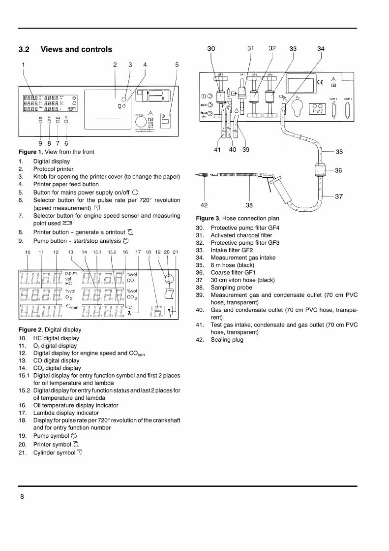
3.2 Views and controls
Figure 1, View from the front
1. Digital display2. Protocol printer3. Knob for opening the printer cover (to change the paper)4. Printer paper feed button5. Button for mains power supply on/off6. Selector button for the pulse rate per 720� revolution
(speed measurement)7. Selector button for engine speed sensor and measuring
point used8. Printer button -- generate a printout9. Pump button -- start/stop analysis
Figure 2, Digital display10. HC digital display11. O2 digital display12. Digital display for engine speed and COcorr13. CO digital display14. CO2 digital display15.1 Digital display for entry function symbol and first 2 places
for oil temperature and lambda15.2 Digital display for entry function statusand last 2 places for
oil temperature and lambda16. Oil temperature display indicator17. Lambda display indicator18. Display for pulse rate per 720� revolution of the crankshaft
and for entry function number19. Pump symbol20. Printer symbol21. Cylinder symbol
Figure 3, Hose connection plan
30. Protective pump filter GF431. Activated charcoal filter32. Protective pump filter GF333. Intake filter GF234. Measurement gas intake35. 8 m hose (black)36. Coarse filter GF137 30 cm viton hose (black)38. Sampling probe39. Measurement gas and condensate outlet (70 cm PVC
hose, transparent)40. Gas and condensate outlet (70 cm PVC hose, transpa-
rent)41. Test gas intake, condensate and gas outlet (70 cm PVC
hose, transparent)42. Sealing plug

9
Figure 4, Back
50. Socket for oil temperature sensor51. Socket for inductive clip--on pickup52. Socket for connecting cable term. 1, TD/TN, B-- or vehicle
earth53. Cap for O2 sensor54. Mains socket and mains fuse55. Optional second serial port56. Serial port
3.3 Operating method
3.3.1 Warming--up period
The warming--up period of the unit lasts 3 minutes. Noanalysis is possible during this period.
No warming--up period is required for entry mode (seechapter 5). Allowance must therefore be made for zeropoint drift when analysing in this mode.
3.3.2 Drift correction
The analyzer will automatically carry out a system testwith ambient air 15 minutes after analysis hascommenced. If analysis is being carried out at that time,the test will be postponed until its completion.
3.3.3 ��� system test
The analyzer switches a solenoid valve over to ambientair for the system test. Zero gas is used for flushing theunit for 30 seconds.
Hydrocarbons are removed from the inducted ambient airby an activated charcoal filter.
The drift of the oxygen measurement and the zero pointsof HC, CO and CO2 measurements are monitored andadjusted.
3.3.4 Air ratio measurement
The analyzer calculates the lambda air ratio from theconcentrations of HC, CO, CO2 and oxygen measured.Precise oxygen measurement is important for thepurposes of lambda calculation. If this is active, the oiltemperature display will be switched over to lambdashould a CO2 concentration greater than 2 % bemeasured.
3.3.5 Corrected CO concentration (COcorrected)
The analyzer will calculate the actual concentration of CO(COcorrected) from the concentration of CO and CO2.
VAS 5067:Allowance is then made for leaks in the exhaust system.The corrected CO concentration is only printed out on theanalysis protocol and if no engine speed is measured it isindicated in the digital display (12).
3.3.6 Oxygen measurement
The exhaust--gas analyzer is equipped with an O2 sensor.This sensor is screwed to the rear of the analyzer in thesocket provided (53).
Oxygen measurement is automatically adjusted to anoxygen content of 20.9 % by volume of air. It can beswitched off (see chapter 5.3.6).
The O2 sensor is a part subject to wear.

10
3.4 Initial commissioning
Caution! Min. height of installation location: 250 mmfrom floorMin. length of outlet hoses: 300 mm
Note: These specifications must be observed toensure that the condensate generatedconstantly flows off, the accuracy ofmeasurement is guaranteed and that themeasuring system is adequately protectedagain contamination.
For a hose connection plan, see Figure 3.
� Connect the exhaust sampling probe to the prefilter(36) using the 30 cm viton hose (37).
� Connect the sampling hose (35) to the prefilter.
� Connect the sampling hose to the gas intake (34) onthe analyzer.
Caution! Connect 3 70 cm PVC hoses (39/40/41) tothe gas outlets. Lead the hoses into anopen container to collect condensation.Observe the voltage specifications shownon the rating plate!
� Connect the analyzer to a properly earthedtwo--pole--and--earth socket outlet using the powerlead supplied.
3.5 Exhaust analysis on 2--strokeengines
3.5.1 Technical background
Vehicles with 2--stroke engines emit higher levels ofhydrocarbon (HC) emissions than 4--stroke engines andthey also emit oil. Oil for the most part consists ofhydrocarbons. If no measures are taken to prevent it fromhappening, this oil is deposited on the sides/walls of theexternal gas path (sensor, hose, filter).
These deposits lead to an HC concentration beingindicated (residual value indication) even when exhaustanalysis is not being carried out. This means, then, thatthe actual HC value measured during an HCmeasurement is distorted by the amount of this residualvalue (increased).
This effect, referred to by experts as ”hang--up”,manifestsitself in all exhaust--gas analyzers that are capable ofmeasuring the HC concentration and is not specific to anyparticular make.
These deposits can be prevented to the greatest possibleextent through the use of activated charcoal filters. Thesefilters bind and neutralise for the most part oil and volatilehydrocarbons. Filters of this kind have a limited servicelife. They are used on the sensor in the gas pathdownstream of the coarse filter.
Deposits can also occur in small quantities downstreamof the activated charcoal filter on the sides of the hose.They must be purged by means of one or other of the twoalternatives we offer.
3.5.2 Solutions
D 1st alternativeFlushing using the integral pump in the analyzer.
The pump must be left switched on after each 2--strokemeasurement until the HC value displayed has droppedto below 20 ppm. The flushing time depends on themagnitude of the residual value. It can take approx. 30minutes, but it may also take considerably longer.

11
For this alternative, only the activated charcoal filter isadditionally required for 2--stroke exhaust analysis. Thefilter must always be inserted in the gas path during thesemeasurements.
1. Coarse filter2. Activated charcoal filter3. Sampling hose, material viton
D 2nd alternativeIn order to reduce the flushing times drastically, i.e. toincrease the availability of the units after a 2--strokeanalysis, we recommend that you use a second externalgas path.
The HC deposits can then be purged quickly by blowingout the hose with compressed air.
1. Coarse filter2. Activated charcoal filter3. Sampling hose, viton4. Sampling hose set viton (8 + 0,3 + 0,3) m long
3.5.3 Notes
-- Activated charcoal filters bind hydrocarbons.-- The second sampling hose and activated charcoal filtermust only be used for CO measurements, not for HCand lambda measurements.

12
4 Exhaust analysis
4.1 Commissioning
The instructions in chapter 3.4 must be carried out beforethe unit is switched on for the first time.
4.1.1 The following must be tested before exhaustanalysis commences:
-- the sampling probe (for damage and blockages);-- the coarse filter (for presence and damage);-- the sampling hose (for damage and blockages);-- filters GF2, GF3 and GF4
4.1.2 Switch on the unit
The warming--up sequence may run differently, depend--ing on the parameterisation of the unit (see chapter 5).
� Press the mains button (5)
Segment test is carried out. Duration: 10 s.
������� �������
������� �������
������� ������� � �
Unit version and the current date are displayed. Duration:5 s, for example:
� � � � � � �
� �� � � � � �
� � � � �
Startup with display of the remaining warming--up time.Opportunity to carry out a leak test. Pump symbol (19)flashes. Duration: 3 min.
� � � � ��
� � � � � �
� � � � � � �
���. system check. Duration: 30 s.
� � �� � � ��
� � �� � � ��
Standby mode
� � � � � � � �
� � � � � � � �
� � � � � � � � �
4.1.3 Leak testing
A leak test must be carried out every 24 hours. Theexhaust--gas analyzer automatically prompts you to doso.
A leak test can be carried out on the sampling systemduring the warming--up period.
Warning! Danger! Risk of burning yourself!Depending on how long exhaust--gasanalysis takes, the sampling probe of theanalyzer can be very hot.
� Activate the test by pressing the pump button (9)
The pump symbol (19) flashes.
� � �� � � � �
�
� The sampling probe (38) must then be sealed with thesealing plug (42).
� Then start the leak test by pressing the pump button(9).
� � � � �
� � �� � � � �
The leak time is displayed in the display window (13).
� Remove the sealing plug (42) immediately after theleak time has elapsed.

13
If the leak test is successful, the display will revert towarming up mode. Otherwise, a fault will be displayed!
4.2 Requirements for exhaust analysis
-- The engine must be warm (oil temperature > 60 _C)
-- No aids to starting (automatic or manual) must beoperating.
-- The exhaust pipe must not leak.
-- The engine must have the ignition settings specified bythe manufacturer (dwell angle, ignition timing and idlingspeed).
4.3 Preparation of exhaust analysis
Warning! Danger: exhaust fumes are poisonous!
Exhaust fumes must be extracted fromconfined spaces.With exhaust systems with one silencer, buttwo tailpipes, both tailpipes must be fed into acommon collector pipe.
It is possible when connecting the clip--onpickup that physical injury and/or damage toproperty may arise due to flashover if theignition system is faulty. For this reason,always connect an earthing lead beforeoperating the exhaust--gas analyzer.
Note: The sampling probe (38) may be insertedinto the exhaust tailpipe only afterconditioning has been performed or onlywhile a measurement is running (seechapters 4.6, 4.7).
� Switch off the engine and ignition.
� When measuring the exhaust--gas emissionsupstream of the catalytic converter, the full length ofthe sampling hose (8 m) must be used between theanalyzer and the sampling point in the vehicle.Observe the temperature limit for the viton hose(max. 200 _C).The filter (36) must also be used.
� Start analysis by pressing the pump button (9).
When using the special ”oil temperature sensor” and”inductive clip--on pickup”:
� Make an earthing connection between theexhaust--gas analyzer and the vehicle.
� Clip the inductive clip--on pickup to an ignition cable inthe engine compartment at such a point that it is as faraway as possible from any other ignition cables.
� Set the number of ignition pulses using the button(6) (see chapter 6.2.4).
� Select the sensor and measuring point using thebutton (7) (see chapter 6.2.3).
� Adjust the oil temperature sensor to the length of thedipstick with the sealing cone.
� Insert the oil temperature sensor into the cylinder blockinstead of the dipstick.
� Start the engine.
4.4 Recalibration with test gas
Particularly high long--term stability is a feature of theanalyzer. Nevertheless, legal requirements may entail itsrecalibration at regular intervals. Service agencies set therequisite parameters. Before the calibration period hasexpired, the following warning is displayed:
� � � � � �
� � � � � � � �
�
The unit must then be recalibrated with test gas up toexpiration of the calibration period, in accordance withchapter 8.10.
4.5 Maintenance
Regularmaintenancewill ensure that the unit will continueto operate reliably and accurately. If the appointed date formaintenance becomes overdue, the followingmessage isdisplayed in standby mode to remind you thatmaintenance is necessary:
� � � � � �
� � � � � �
You have to update the maintanance date in entry mode(see chapter 5.3.5). Maintenance see chapter 8.
14
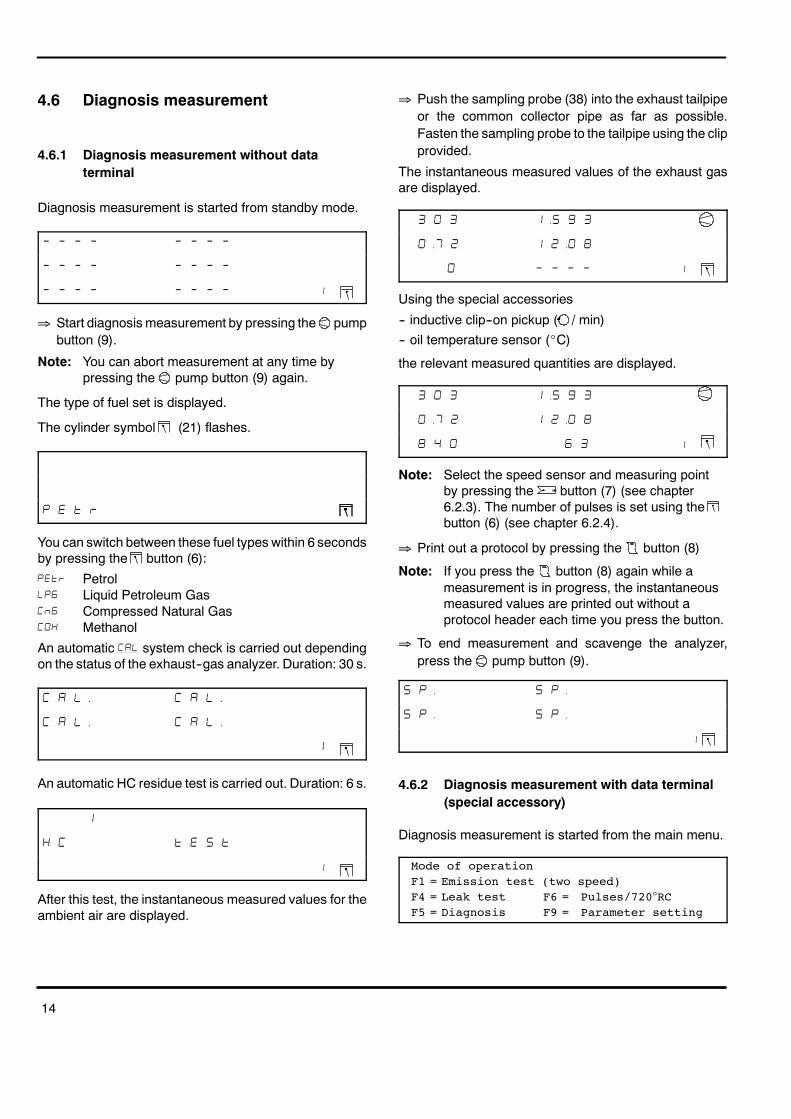
4.6 Diagnosis measurement
4.6.1 Diagnosis measurement without dataterminal
Diagnosis measurement is started from standby mode.
� � � � � � � �
� � � � � � � �
� � � � � � � � �
� Start diagnosis measurement by pressing the pumpbutton (9).
Note: You can abort measurement at any time bypressing the pump button (9) again.
The type of fuel set is displayed.
The cylinder symbol (21) flashes.
� � � �
You can switch between these fuel types within 6 secondsby pressing the button (6):
�� Petrol��� Liquid Petroleum Gas� � Compressed Natural Gas��� Methanol
An automatic ��� system check is carried out dependingon the status of the exhaust--gas analyzer. Duration: 30 s.
� � �� � � ��
� � �� � � ��
�
An automatic HC residue test is carried out. Duration: 6 s.
�
� � � � � �
�
After this test, the instantaneous measured values for theambient air are displayed.
� Push the sampling probe (38) into the exhaust tailpipeor the common collector pipe as far as possible.Fasten the sampling probe to the tailpipe using the clipprovided.
The instantaneous measured values of the exhaust gasare displayed.
� � �� � �
�� � � �� �
� � � � �
Using the special accessories
-- inductive clip--on pickup ( / min)-- oil temperature sensor (_C)
the relevant measured quantities are displayed.
� � �� � �
�� � � �� �
� � � �
Note: Select the speed sensor and measuring pointby pressing the button (7) (see chapter6.2.3). The number of pulses is set using thebutton (6) (see chapter 6.2.4).
� Print out a protocol by pressing the button (8)
Note: If you press the button (8) again while ameasurement is in progress, the instantaneousmeasured values are printed out without aprotocol header each time you press the button.
� To end measurement and scavenge the analyzer,press the pump button (9).
�� ��
�� ��
�
4.6.2 Diagnosis measurement with data terminal(special accessory)
Diagnosis measurement is started from the main menu.
Mode of operationF1 = Emission test (two speed)F4 = Leak test F6 = Pulses/720�RCF5 = Diagnosis F9 = Parameter setting
15
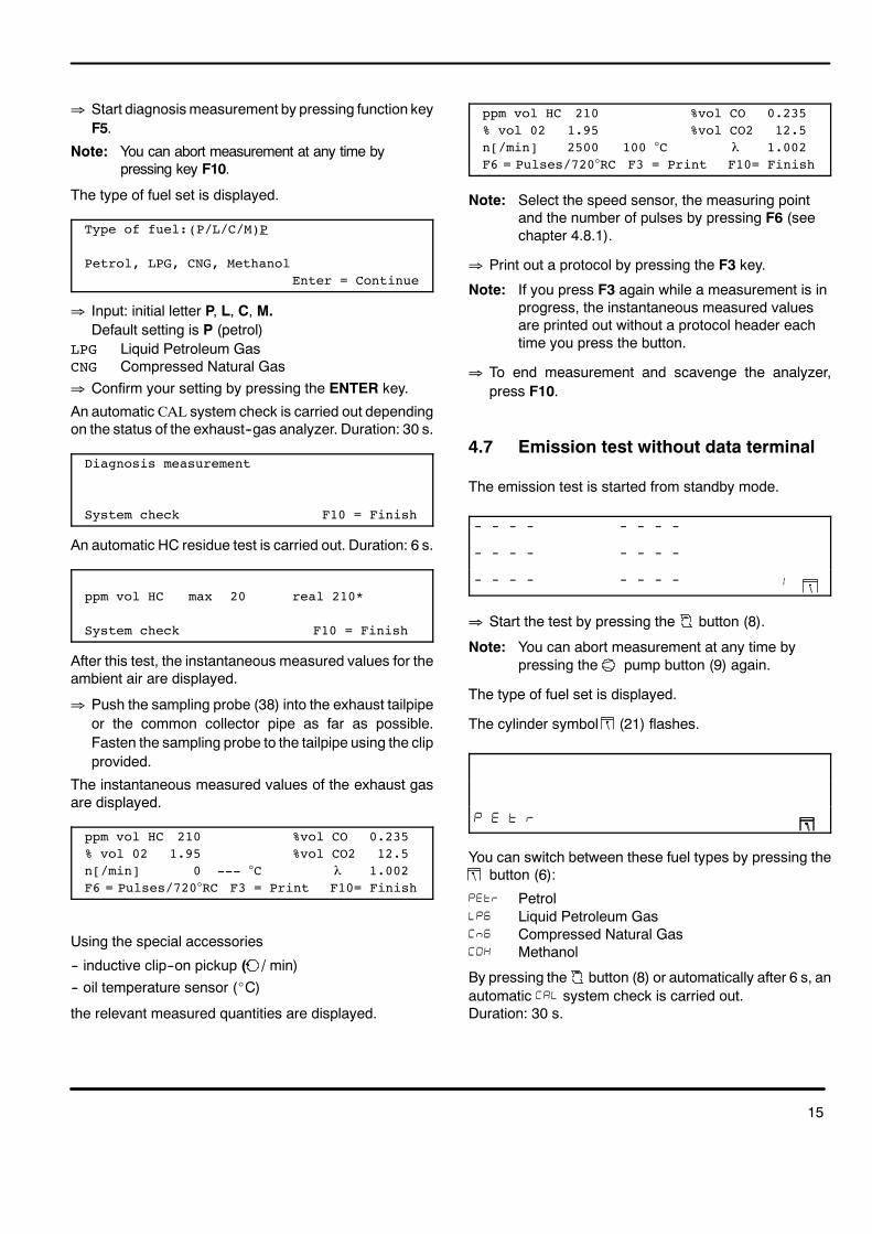
� Start diagnosismeasurement by pressing function keyF5.
Note: You can abort measurement at any time bypressing key F10.
The type of fuel set is displayed.
Type of fuel:(P/L/C/M)P
Petrol, LPG, CNG, MethanolEnter = Continue
� Input: initial letter P, L, C, M.Default setting is P (petrol)
LPG Liquid Petroleum GasCNG Compressed Natural Gas� Confirm your setting by pressing the ENTER key.
An automatic CAL system check is carried out dependingon the status of the exhaust--gas analyzer. Duration: 30 s.
Diagnosis measurement
System check F10 = Finish
An automatic HC residue test is carried out. Duration: 6 s.
ppm vol HC max 20 real 210*
System check F10 = Finish
After this test, the instantaneous measured values for theambient air are displayed.
� Push the sampling probe (38) into the exhaust tailpipeor the common collector pipe as far as possible.Fasten the sampling probe to the tailpipe using the clipprovided.
The instantaneous measured values of the exhaust gasare displayed.
ppm vol HC 210 %vol CO 0.235% vol 02 1.95 %vol CO2 12.5n[/min] 0 --- �C � 1.002F6 = Pulses/720�RC F3 = Print F10= Finish
Using the special accessories
-- inductive clip--on pickup ( / min)-- oil temperature sensor (_C)
the relevant measured quantities are displayed.
ppm vol HC 210 %vol CO 0.235% vol 02 1.95 %vol CO2 12.5n[/min] 2500 100 �C � 1.002F6 = Pulses/720�RC F3 = Print F10= Finish
Note: Select the speed sensor, the measuring pointand the number of pulses by pressing F6 (seechapter 4.8.1).
� Print out a protocol by pressing the F3 key.
Note: If you press F3 again while a measurement is inprogress, the instantaneous measured valuesare printed out without a protocol header eachtime you press the button.
� To end measurement and scavenge the analyzer,press F10.
4.7 Emission test without data terminal
The emission test is started from standby mode.
� � � � � � � �
� � � � � � � �
� � � � � � � � �
� Start the test by pressing the button (8).
Note: You can abort measurement at any time bypressing the pump button (9) again.
The type of fuel set is displayed.
The cylinder symbol (21) flashes.
� � � �
You can switch between these fuel types by pressing thebutton (6):
�� Petrol��� Liquid Petroleum Gas� � Compressed Natural Gas��� Methanol
By pressing the button (8) or automatically after 6 s, anautomatic ��� system check is carried out.Duration: 30 s.

16
� � �� � � ��
� � �� � � ��
�
An automatic HC residue test is carried out. Duration: 6 s.
�
� � � � � �
�
The conditioning phase is started automatically.
� � � � � �
� � �
Note: Select the speed sensor and measuring pointby pressing the button (7) (see chapter6.2.3). The number of pulses is set using thebutton (6) (see chapter 6.2.4).
Wait until the printer symbol (20) flashes.
When the normal operating oil temperature has beenreached (see manufacturer’s specifications):
� push the sampling probe (38) into the exhaust tailpipeor the common collector pipe as far as possible.Fasten the sampling probe to the tailpipe using the clipprovided.
� end conditioning by pressing the printer button (8)and begin measurement.
Depending on how the analyzer has been parameterised(see chapter 5.3.15, Parameterisation of the sequencetest), the measurement can be carried out following 2different sequences:
-- Measurement in which measurement taken at high idlespeed comes second in sequence. Defaultparameterisation. Switchover frommeasurement at idlespeed to measurement at high idle speed is performedmanually.
-- Measurement in which measurement taken at high idlespeed comes first in sequence. Switchover frommeasurement at high idle speed tomeasurement at idlespeed is performed automatically.
4.7.1 Measurement in which measurement taken athigh idle speed comes second in sequence(closed--loop cat., open--loop cat., no cat.)
D Measurement at idle speedThe actual engine speed (12) and maximum permissibleidle speed (15) are displayed.
� �
� �
Note: If the actual engine speed is higher than themaximum permissible value, the speed indicator(12) flashes and automatic switchover to thegas analysis time does not take place.
If the actual engine speed is correct or if the speedoverride is activated (see chapter 5.3.15,Parameterisation of the test sequence, setting EU.EO,parameter drbr.), the gas analysis time lasting 30 s beginsafter you press the button (8).
� � � �
� � �� �
� �� � �
Once the gas analysis time has expired, the printersymbol (20) flashes
� Press the button (8).
The measured values taken during measurement at idlespeed are stored and measurement at high idle speed isautomatically started.
Note: If measurement at high idle speed is not becarried out (e.g. for a vehicle without a catalyticconverter (cat.), the button (8) must bepressed once more within the space of 3 s. Aprotocol is printed out with the header, theresults of the first measurement and theprotocol footer as parameterised. Theexhaust--gas analyzer is then scavenged.
D Measurement at high idle speedThe actual engine speed (12) and required speed (15) aredisplayed.
� � �

17
Note: The value in the speed window can beincreased by pressing the button (6) (100rpm per press of the button; setting range: 1500-- 3300 rpm + 400 rpm). When the maximumsettable value is reached, the valueautomatically jumps to the lowest value.If the actual speed does not agree with thevalue in the speed window, the speed indicator(12) flashes and automatic switchover to thegas analysis time does not take place.
If the actual engine speed is correct or if the speed over--ride is activated (see chapter 5.3.15, Parameterisation ofthe test sequence, setting EU.EO, parameter drbr.), thegas analysis time lasting 30 s begins after you press the
button (8).
� � � �
� � �� �
� � �� � �
Once the gas analysis time has expired, the measuredvalues taken during the second measurement areautomatically stored, the protocol printed out andmeasurement terminated.
The exhaust--gas analyzer is then scavenged.
�� ��
�� ��
�
4.7.2 Measurement in which measurement takenat high idle speed comes first in sequence(closed--loop cat. only)
D Measurement at high idle speed
The actual engine speed (12) and speed window (min.and max. of required speed (11 + 14)) are displayed.
� � �
� �
Note: The value in the speed window can beincreased by pressing the button (6)(100 rpmper press of the button; setting range: 1500 --3300 rpm + 400 rpm). When the maximumsettable value is reached, the valueautomatically jumps to the lowest value.
If the actual speed does not agree with thevalue in the speed window, the speed indicator(12) flashes and automatic switchover to thegas analysis time does not take place.
If the actual engine speed is correct, the gas analysis timelasting 30 s begins.
� � � �
� � �� �
� � �� � � �
Once the gas analysis time for measurement at high idlespeed has expired, the analyzer automatically switchesover to measurement at idle speed.
D Measurement at idle speedThe actual engine speed (12) and maximum permissibleidle speed (15) are displayed.
� �
� �
Note: If the actual engine speed is higher than themaximum permissible value, the speed indicator(12) flashes and automatic switchover to thegas analysis time does not take place.
If the actual engine speed is correct or if the speed over--ride is activated (see chapter 5.3.15, Parameterisation ofthe test sequence, setting EU.EO, parameter drbr.), thegas analysis time lasting 30 s begins after you press the
button (8).
� � � �
� � �� �
� � � �
Once the gas analysis time has expired, the printersymbol (8) flashes.
� Press the button (8).
The measured values taken are stored, the protocolprinted out and measurement terminated.
The exhaust--gas analyzer is then scavenged.
�� ��
�� ��
�

18
4.8 Emission test with data terminal(special accessory)
The following basic menu is displayed on the dataterminal:
Mode of operationF1 = Emission test (two speed)F4 = Leak test F6 = Pulses/720�RCF5 = Diagnosis F9 = Parameter setting
4.8.1 Function keys on the data terminal
F1 Emission test
Official test for vehicles with spark--ignition engines withclosed--loop--controlled fuel management system, otherexhaust emission control systems and without exhaustemission control system.
F3 Print
Leads to a printout on the integral or externally connectedprinter.
-- In the diagnosis measurement and emission testsequences, the instantaneous measured values areprinted out.
-- In the emission test sequences, function key F3 is notrequired since the printouts are made automatically.
F4 Leak test
Warning! Risk of burning yourself!The sampling hose of the exhaust--gasanalyzer may still be very hot after theprevious measurement.
-- The sampling probe (38) must be sealed with thesealing plug (42).
Leak testSampling sensor sealing withchecking bushSampling sensor sealed? (Y)
-- The unit nowmeasures the pressure drop over a periodof 50 s. The time is counted down from 50 s to zero.
-- The message ”Leak test OK” and prompt”Remove checking bush” are displayed.
-- If a leak has been detected in the system, anappropriate fault message will be displayed.
F5 Diagnosis measurement
After calibration, the following mask is displayed:
Type of fuel:(P/L/C/M)P
Petrol, LPG, CNG, MethanolEnter = Continue
For further description of diagnosis measurement seechapter 4.6.2.
F6 Entering the engine speed measuring point andnumber of pulses
To enable universal engine speed measurement ondifferent ignition systems (single--/dual--spark, RUV), thesystem offers the ability to choose an engine speed(RPM) measuring point and RPM sensor (trigger clip--onpickup, secondary, primary/connecting cable term. 1/B--)and to set the number of pulses picked up every 2revolutions of the crankshaft.
The setting can be changed in standby mode, duringdiagnosis measurement and during the first step of theemission test by carrying out an engine speedmeasurement.
D Entering the RPM measuring point
RPM sensors measuring point EFSn[/min] 0 at pulses/720�RC = 1
RPM sensors measuring point OK? (Y/N)Y
� Enter Y (yes) to move on to entering the number ofpulses
� After entering N (no), you can change the RPMmeasuring point
Selecting the rpm sensors measuring pointn[/min] 0 at pulses/720�RC = 1EFS, DFS, I-Prim, Prim.-L (E/D/I/P) ? E
� Enter the initial letter: E, D, I or PDefault: E (EFS)
� Continue by pressing ENTER
RPM sensors measuring point EFSn[/min] 2500 at pulses/720�RC = 1
RPM sensors measuring point OK? (Y/N)Y
� Enter Y (yes) to move on to entering the number ofpulses
� After entering N (no), the program returns to changingthe RPM measuring point

19
D Entering the number of pulses
Number of pulses/720� rev. of crankshaftn[/min] 2500 at pulses/720�RC = 1Measuring point EFSNumber of pulses OK? (Y/N)Y
� Enter Y (yes) to end input of the RPMmeasuring pointand number of pulses
� After entering N (no), you can change the number ofpulses
Setting the pulse rate/720�rev. of crankn[/min] 2500 at pulses/720�RC = 1
� Enter a number: 1...6, 8, 10 or 12Standard is 1
� Continue by pressing ENTER
Number of pulses/7200� rev. of crankshaftn[/min] 2500 at pulses/720�RC = 4Measuring point EFSNumber of pulses OK? (Y/N)Y
� Enter Y (yes) to end input of the RPMmeasuring pointand number of pulses
� After entering N (no), the program returns to changingthe number of pulses
F9 Entering the workshop address, unit ID and date
The display of the data terminal displays the input maskfor the protocol header (workshop address), registration(number) plate, signature, date and time, and final(advertising) text. In addition, the version number and thenext maintenance date are displayed.
P = Protocol head VERS:N = Number plate Maintenance: 15.01.97S = Signature A = AdvertisingD = Date / time F10 = Finish
F10 Finish
This key enables you to abort a measuring procedure atany time. The program returns to the main menu.
Timeout
If no entry is made or an operator prompt is not replied towithin 10 minutes, the analyzer automatically abortsmeasurement (a statutory requirement).Message: ”Emission test was interrupted”
4.8.2 Measurement in which measurement taken athigh idle speed comes second in sequence(closed--loop cat.,open loop cat.,no cat.)
Note: Measurement at high idle speed is onlyperformed on vehicles fitted with a closed--loopcatalytic converter (see chapter 5.3.15,Parameterisation of the sequence test).
The emission test is started from the main menu.
Mode of operationF1 = Emission test (two speed)F4 = Leak test F6 = Pulses/720�RCF5 = Diagnosis F9 = Parameter setting
� Start the emission test by pressing key F1.
Note: You can abort the emission test at any time bypressing key F10.
The type of fuel set is displayed.
Type of fuel:(P/L/C/M)P
Petrol, LPG, CNG, MethanolEnter = Continue
� Input: initial letter P, L, C, MStandard is P (petrol)
LPG Liquid Petroleum GasCNG Compressed Natural Gas� Confirm your setting by pressing the ENTER key.An
automatic CAL system check is carried out for 30 s.
Emission test
System check F10 = Finish
An automatic HC residue test is carried out. Duration: 6 s.
ppm vol HC max 20 real 210*
System check F10 = Finish
The conditioning phase is started.
Type of fuel: PetrolOil temperatur [�C]: 82Real engine running speed n[min]: 800F6= Pulses/720�RC Enter = Continue

20
Note: Select the speed sensor, the measuring pointand the number of pulses by pressing F6 (seechapter 4.8.1).
� Push the sampling probe (38) into the exhaust tailpipeor the common collector pipe as far as possible.Fasten the sampling probe to the tailpipe using the clipprovided.
� Continue by pressing ENTER
D Measurement at idle speed
Maximum engine running speed n[/min]:1300Real engine running speed n[/min]: 2550Is sampling probe in exhaust pipe ?F3= Continue F6=Pulses/720�RC Change RPM!
Note: If the actual engine speed is lower than themaximum permissible value, automaticswitchover to the gas analysis time does nottake place.
� Bring the engine up to idle speed.
If the actual engine speed is correct or if the speedoverride is activated (see chapter 5.3.15,Parameterisation of the test sequence, setting EU.EO ,parameter drbr.), the gas analysis time lasting 30 s beginsafter you press F3.
ppm vol HC 214 %vol CO 0.156% vol O2 21.09 %vol CO2 13.04n[/min] 1400 � -.---F6 = Pulses/720�RC Gas running time: 29
Once the gas analysis time has expired, the followingmask is displayed:
ppm vol HC 214 %vol CO 0.156% vol O2 21.09 %vol CO2 13.04n[/min] 800 � -.---F6= Pulses/720�RC Enter = Continue
� Continue by pressing ENTER
The measured values taken during measurement at idlespeed are stored.
ppm vol HC 214 %vol CO 0.156% vol O2 21.09 %vol CO2 13.04n[/min] 800 � -.---F3 = Quit/Print Enter = Continue
Note: If measurement at high idle speed is not becarried out (e.g. for a vehicle without a catalyticconverter (cat.), the F3 key must be pressedonce more within the space of 5 s.A protocol is printed out in accordance with the
parameters set. The exhaust--gas analyzer isthen scavenged.
� Switch directly to measurement at high idle speed bypressing ENTER or wait for 5 s for this secondmeasurement to be started automatically.
D Measurement at high idle speed
Required engine running speedn[/min] 2500 +/- 200Real engine running speed n[/min]: 800Speed range 1700-3500 rpm ENTER = Change
Note: The required engine speed can be increased bypressing the ENTER key (100 rpm per press ofthe key; setting range: 1700 -- 3500 rpm � 200rpm). When the maximum settable value isreached, the value automatically jumps to thelowest value.
If the actual speed does not agree with therequired speed by � 200 rpm, automaticswitchover to the gas analysis time does nottake place.
� Bring the engine up to required speed and hold it there.
If the actual engine speed is correct, the gas analysis timelasting 30 s begins.
ppm vol HC 214 %vol CO 0.156% vol O2 21.09 %vol CO2 13.04n[/min] 800 � -.---F6 = Pulses/720�RC Gas running time: 29
Once the gas analysis time has expired, measurement isterminated automatically, the measured values takenduring measurement at high idle speed are stored and aprotocol is printed out in accordance with the parametersset.
The exhaust--gas analyzer is then scavenged.
Emission test
Flush
4.8.3 Measurement in which measurement takenat high idle speed comes first in sequence(closed--loop cat. only)
Measurement in which measurement taken at high idlespeed comes first in the sequence is performed along thesame lines as described in chapter 4.8.2. This mode ofmeasurement is, however, not suitable for vehicles notfitted with a catalytic converter.

21
The switchover from measurement at high idle speed tomeasurement at idle speed takes place automatically.
Measurement is terminated manually.
4.9 Copy of the protocol of an exhaust--emission measurement
When the exhaust--gas analyzer is in standby mode afteran exhaust--emission measurement, you can print out acopy of the protocol printout of the last measurement.
Note: If during this procedure you do not press abutton during any period of 6 s, the program willautomatically return to standby mode.
� � � � � � � �
� � � � � � � �
� � � � � � � � �
The exhaust--gas analyzer is in standby mode.
� Press the (7) and (6) buttons at the same time.
The values from the last measurement at idle speed aredisplayed:
� Press the button (6).
The values from the last measurement at high idle speedare displayed:
� � � �
� � �� �
� �� � �
� Press the button (6) once again.
A copy of the protocol printout from the last exhaust--emission measurement is printed out.
Note: This printout is marked with the word Copyabove the protocol header.

22
4.10 Protocol printouts
Different protocols are printed out depending on the testprocedure performed.
Note: The content of the protocol printouts dependson the parameters set.
D Protocol printout of a diagnosis measurement
------------------------>VAS 5067 V5.72 <------------------------
Unit ID
Car Gold GarageHattenham Drive 4New HasletownTel.: 01234/567-0Fax : 01234/567-99------------------------
------------------------27.06.96 14:0127.06.96 14:01------------------------
PEtr�C 801/min 600% vol CO 0.098% vol CO2 14.33% vol O2 0.53ppm vol HC 20
Protocol header(6 lines)
Date/time
Type of fuel
Measurement resultsin acc. withparameters sets*
If you press the button (8) again while a measurementis in progress, the instantaneous measured values areprinted out without a protocol header.
------------------------
27.06.96 14:04------------------------
PEtr�C 801/min 600% vol CO 0.098% vol CO2 14.33% vol O2 0.53ppm vol HC 20
* See chapter 5.3, Entry mode functions, entry functionnos. 2, 3 and 6.
D Protocol printout of an emission measurement, 1st and2nd measurements
------------------------>VAS 5067 V5.72 <------------------------
Unit ID
Car Gold GarageHattenham Drive 4New HasletownTel.: 01234/567-0Fax : 01234/567-99------------------------27.06.96 14:11------------------------
PEtr------------------------Results 1st measurement
�C 801/min 600% vol CO 0.098% vol CO2 14.33% vol O2 0.53ppm vol HC 20------------------------Results 2nd measurement
�C 801/min 2480% vol CO 0.098% vol CO2 14.33% vol O2 0.53ppm vol HC 20------------------------Number plate
..................------------------------Signature
..................------------------------<<< Have a nice day >>>
Protocol header *(6 lines),freely assignable
Date/time *
Type of fuel
Mesurement resultsin acc. withparameters sets *
Measurement resultsin acc. withparameters sets *
Freely assignable text(number plate)*
Freely assignabletext*
Freely assignable ad-vertising text*
Note: If you request a copy of the protocol printout,this copy is marked with the word Copy abovethe protocol header.
* See chapter 5.3, Entry mode functions, entry functionno. 15.

23
D Protocol printout of an emission measurement, 1stmeasurement only
------------------------>VAS 5067 V5.72 <------------------------
Car Gold GarageHattenham Drive 4New HasletownTel.: 01234/567-0Fax : 01234/567-99
------------------------27.06.96 14:11------------------------
PEtr------------------------Results without cat.
�C 801/min 600% vol CO 0.098% vol CO2 14.33% vol O2 0.53ppm vol HC 20------------------------Number plate
..................------------------------Signature
..................------------------------<<< Have a nice day >>>

24
5 Functions of parameterisationand test functions
Various unit parameters are set in entry mode.
There is no warming--up time in entry mode. Ifmeasurements are carried out in this mode, the zero pointdrift has to be observed.
Note: A flashing LED is shown here in bold print.��� Display normal��� Display flashing
5.1 Accessing entry mode
Entry mode is accessed in the following way:
� Press the mains switch (5).
The following display (1) will appear:
������� �������
������� �������
������� ������� � �
Hold down the printer button (8) for as long as thisdisplay is present.
5.2 Operation in entry mode
Digital displays 10 -- 14 display values or symbols whichcan be viewed or changed.
The symbols of the entry function are displayed in digitaldisplay 15.1.The status of the entry function is displayed in digitaldisplay 15.2:
-- An. Function display-- Ei. Entry-- Ab. Routine running
The number of the entry function is displayed in digitaldisplay 18.
Meaning of the buttons
Button (9) -- Pressing the button will reduce thenumber of the entry function.
-- Selection of the lower setting withinan application (if possible).
-- Reduction of the level set.
Button (8) -- Pressing the button will implementadjustment of a selectedapplication.Example: the display ”An” willchange to ”Ei” or ”Ab” in the displayfield for the oil temperature.
-- Activation of a setting in a settingapplication.
-- Adoption of a setting and exit fromthe application.
Button (7) -- Pressing the button will increasethe number of the entry function
-- Selection of the higher settingwithin an application (if possible).
-- Increase of the level set.
Example:
Select an application by pressing the
� button (9) or button (7)
Activate an application by pressing the
� button (8)
Select a setting within an application by pressing the
�
Activate a setting by pressing the
� button (8)

25
5.3 Entry mode functions
Number of theentry function Symbol Function
0
123456789
1011121314
15
171819
�����
�����
�����
����
����
� ���
���
�����
�����
���
�����
�����
�����
���
� ���
�����
�����
�����
����
Recalibration with test gas (AJfunction)Entry of date and timeLambda calculation on/offCOcorrection calculation on/offUpdating the maintenance dateParameter printoutO2 measurement on/offNumber of printoutsPrinter selectionConfiguration of the analog currentinterfaceAnalysis mode, oxygen measurementPump in entry mode on/offAnalysis mode, infrared channelsConfiguration of serial portsSwitchover between old and newMOT protocolParameterisation of the test se-quenceCalibration dataUnit dataExit from entry mode
5.3.1 Calibration with certificated test gas
Note: The relevant EU directive stipulates thatexhaust--gas analyzers must be recalibratedwith certificated test gas at regular intervals byexpert personnel. See chapter 8.10 for therelevant procedure.
Select the AJ function by pressing
� the button (9) or button (7).
� � � � � ��� �
See chapter 8.10 for the relevant procedure.
5.3.2 Setting the clock
Select the ”set clock” function by pressing
� the button (9) or button (7).
� ��
� ��� � �
� � � � � ��� � �
Activate the setting function by pressing
� the button (8).
� � � � � � �
� ��� � �
� � � � � ��� �
The number block for the hours flashes.
D Block selectionMove the flashing number block to the next block bypressing
� the button (7).
Move the flashing number block to the previous block bypressing
� the button (9).
Activate the selected block by pressing
� the button (8).
Activate ”End” to exit the setting function.
D Number selectionThe first number in the block selected will flash.
� � � � � � �
� ��� � �
� ! ! � ��� �
Move the selected number to the next one by pressing
� the button (7).
Move the selected number to the previous one bypressing
� the button (9).
Activate the selected numbers by pressing
� the button (8).
� � � � � �
� ��� � �
� ! ! � ��� �
� The numbers can be changed.

26
Activate EndE: to return to block selection.
Increase the selected number by pressing
� the button (7).
Reduce the selected number by pressing
� the button (9).
Adopt the numbers set and return to number selection bypressing
� the button (8).
5.3.3 Lambda calculation on/off
An oxygen sensor is installed for calculating lambda.
���: Lambda will be calculated and displayed whenexhaust analysis is carried out.
" � � � ��� �
�� Lambda will not be calculated.
� � � ��� �
5.3.4 COcorrected calculation on/off
This change of setting is only possible if the COcorrected
switch is set to YES in calibration mode.
���� COcorrected will be calculated and printed out on theprotocol.
�� COcorrectedwill not be calculated.
� � � #�� �
5.3.5 Updating the maintenance date
This switchmust be set toYES andactivatedwhen routinemaintenance is carried out. This deletes the prompt in thedisplay telling you that maintenance must now be carriedout. The date on which the next maintenance work mustbe carried out is now displayed.
� � � � � �
� �� � �
� � � ��� �
5.3.6 Parameter printout
� � � � � ��� � �
� � � � � � �
� � � ��� �
���� Pressing the printer button will produce aparameter printout
�� No printout of parameter
5.3.7 O2 sensor on/off
���: Oxygen measurement is switched on. �: Oxygen measurement is switched off.
" � � # ��� �
5.3.8 Duplicate printout on/off
�� Pressing the printer button will produce a singleprintout.
�� Pressing the printer button will produce twoprintouts.
$ � ��� �
27
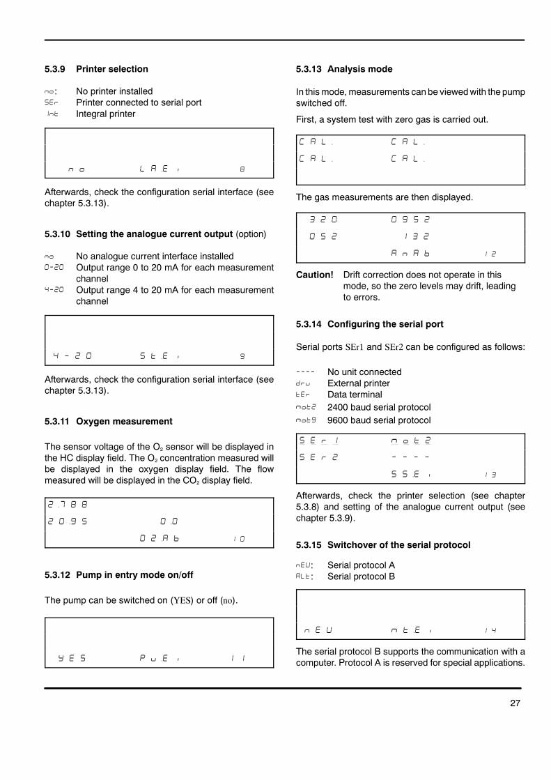
5.3.9 Printer selection
�: No printer installed��� Printer connected to serial port� � Integral printer
� � � ��� �
Afterwards, check the configuration serial interface (seechapter 5.3.13).
5.3.10 Setting the analogue current output (option)
�� No analogue current interface installed����� Output range 0 to 20 mA for each measurement
channel����� Output range 4 to 20 mA for each measurement
channel
� � � ��� �
Afterwards, check the configuration serial interface (seechapter 5.3.13).
5.3.11 Oxygen measurement
The sensor voltage of the O2 sensor will be displayed inthe HC display field. The O2 concentration measured willbe displayed in the oxygen display field. The flowmeasured will be displayed in the CO2 display field.
��� � �
� �� �
��� % � �
5.3.12 Pump in entry mode on/off
The pump can be switched on (YES) or off (no).
" � � � &�� � �
5.3.13 Analysis mode
In thismode,measurements can be viewedwith the pumpswitched off.
First, a system test with zero gas is carried out.
� � �� � � ��
� � �� � � ��
The gas measurements are then displayed.
� � � �
� � � �
� � � % � �
Caution! Drift correction does not operate in thismode, so the zero levels may drift, leadingto errors.
5.3.14 Configuring the serial port
Serial ports SEr1 and SEr2 can be configured as follows:
���� No unit connected�� External printer� Data terminal��� 2400 baud serial protocol��� 9600 baud serial protocol
� � � � � � � �
� � � � � � � �
� ��� � �
Afterwards, check the printer selection (see chapter5.3.8) and setting of the analogue current output (seechapter 5.3.9).
5.3.15 Switchover of the serial protocol
��: Serial protocol A��: Serial protocol B
� � � � ��� � �
The serial protocol B supports the communication with acomputer. Protocol A is reserved for special applications.

28
5.3.16 Parameterisation of the test sequence
Note: The parameter of the test sequence can only bechanged if the switch �� is set to ��� incalibration mode. The barring function can onlybe deactivated by a service technician.
Select the ”Parameterisation of the test sequence” funct--ion by pressing
� the button (9) or button (7).
� � � � � ��� � � �
Activate the function by pressing
� the button (8).
� ��� # �
Select the settings under this function by pressing
� the button (9) or button (7).
You use the settings to parameterise the exhaust--gasanalyzer.
The following settings are available:
01
2
34
�����
�����
�����
�����
� ��
Parameterising the environmentParameterising meas. values of 1stmeasurementParameterising meas. values of 2ndmeasurementParameterising the languageEnd and exiting the function
D Setting ����� ”Parameterising the environment”
� ��� # �
Activate the function by pressing
� the button (8).
� �
" � � � � � �
Select the settings under this function by pressing
� the button (9) or button (7).
The following parameters can be changed:
01234
567
��
��
���
��
���
����
���
� ��
Date and time (YES/no)Protocol header (YES/no)Signature (YES/no)Number plate (YES/no)Timing of measurement at high idlespeed (E1/E2)Advertising lineSpeed overrideExit the parameter
Example of how to set a parameter:
The current setting is always displayed for eachparameter (example in this case Date and time).
� �
" � � � � � �
Activate the parameter by pressing
� the button (8).
�
" � � � � � �
Set the parameter by pressing
� the button (9) or button (7).
Adopt the setting and deactivate the parameter bypressing
� the button (8).
-- ”Date and time” parameter
�
" � � � � � �

29
This parameter defines whether or not the current dateand time will be printed on the protocol.
� Date and time are not printed��� Date and time are printed
-- ”Protocol header” parameter
�
" � � � � � �
This parameter defines whether or not the protocolheader with workshop address will be printed on theprotocol.
Note: The protocol header must be entered using thedata terminal.
� Protocol header is not printed��� Protocol header is printed
-- ”Signature” parameter
� $
" � � � �
This parameter defines whether or not the protocol willcontain a line in which the operators can write their nameor signature by hand. The text ”Signature” is entered bythe service agent using the data terminal.
� Signature is not printed��� Signature is printed
-- ”Number plate” parameter
� $
" � � � � �
This parameter defines whether or not the protocol willcontain a line in which the operators can write the chassisnumber of the vehicle tested. The text ”Chassis No.” isentered by the service agent using the data terminal.
� Is not printed��� Is printed
-- ”Timing of measurement at high idle speed” parameter
� $
� � � � � �
This parameter defines whether the measurement athigh idle speed will come before (first in the sequence)or after the measurement at idle speed (second in thesequence).�� Measurement at high idle speed first in sequence�� Measurement at high idle speed first in sequence
-- ”Advertising line” parameter
" � � � � &� �
This parameter defines whether or not the protocol willcontain a line with an advertising text.The advertising text is entered by the service agent usingthe data terminal. � Advertising text is not printed��� Advertising text is printed.
-- ”Speed override” parameter
" � � � � % �� �
This parameter defines whether or not the minimumengine speed for the idle speed measurement and thepreselected speed for the measurement at high idlespeed will be able to be overridden by pressing a button. � Speed is not overridden.��� Speed is overridden.
D SettingEU.EI ”Parameterisingmeas. values of 1stmea-surement”
� ��� � �
Activate the function by pressing
� the button (8).

30
� �
" � � � � �
Select the settings under this function by pressing
� the button (9) or button (7).
The following parameters can be changed:
012345678
��
��
���
��
�
��
� ��
Printout of HC value (YES/no)Printout of CO value (YES/no)Printout of CO2 value (YES/no)Printout of O2 value (YES/no)Printout of engine speed (YES/no)Printout of oil temperature (YES/no)Printout of lambda value (YES/no)Printout of lambda value (YES/no)Exiting the function
Activate the parameter by pressing
� the button (8).
Set the parameter by pressing
� the button (9) or button (7).
Adopt the setting and deactivate the parameter bypressing
� the button (8).
-- ”Printout of HC value” parameter
� $
" � � � � �
This parameter defines whether or not the HC value willbe printed out on the protocol. � HC value is not printed��� HC value is printed
-- ”Printout of CO value” parameter
� $
" � � � # �
This parameter defines whether or not the CO value willbe printed out on the protocol.
� CO value is not printed��� CO value is printed
-- ”Printout of CO2 value” parameter
� $
" � � � # � �
This parameter defines whether or not the CO2 value willbe printed out on the protocol.
� CO2 value is not printed��� CO2 value is printed
-- ”Printout of O2 value” parameter
� $
" � � # � �
This parameter defines whether or not the HC value willbe printed out on the protocol. � O2 value is not printed��� O2 value is printed
-- ”Printout of engine speed” parameter
� $
" � � � �
This parameter defines whether or not the engine speedwill be printed out on the protocol.
� Engine speed is not printed��� Engine speed is printed
-- ”Printout of oil temperature” parameter”
� $
" � � � �
This parameter defines whether or not the oil temperaturewill be printed out on the protocol. � Oil temperature is not printed��� Oil temperature is printed

31
-- ”Printout of lambda value” parameter
� $
" � � � �
This parameter defines whether or not the lambda valuewill be printed out on the protocol.
� Lambda value is not printed��� Lambda value is printed
-- ”Printout of COcorrected value” parameter
� $
" � � � # ! � �
This parameter defines whether or not the COcorrected valuewill be printed out on the protocol.
� COcorrected value is not printed��� COcorrected value is printed
D Setting ����� ”Parameterising meas. values of 2ndmeasurement”
� ��� � �
The parameters for the 2nd measurement are set in thesame way as those for the parameters for the 1stmeasurement.
D Setting ����� ”Language / country selection”
� ��� � �
Activate the function by pressing
� the button (8).
� �
� � �� � ��� � �
Select the setting by pressing
� the button (8).
�
� � �� � ��� � �
The following language settings are available:
0123456789101112
�
����!
��
����
����
���
�
��
�
�
�
"
���#
GermanDanishEnglishSwiss GermanSwiss ItalianSwiss FrenchDutchPolishPortugueseSpanishHungarianJapaneseGeneral
Select the language you want to use by pressing
� the button (9) or button (7).Adopt the setting by pressing
� the button (8).
Note: When the language/country setting is changed,the basic parameters are also changedaccordingly.
5.3.17 Displaying the calibration data
� � � � � ��� � � �
Activate the function by pressing
� the button (8).
Select the settings by pressing
� the button (9) or button (7).The settings can be used to query calibration data.
D Software version and checksum
� � � � � ���
� � � � �
� � � % � ��� � �
32
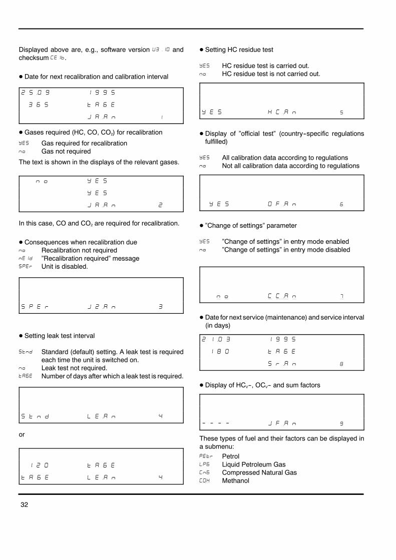
Displayed above are, e.g., software version ����� andchecksum ����.
D Date for next recalibration and calibration interval
� � � � � �
� � � � � �
� ��� � �
D Gases required (HC, CO, CO2) for recalibration
��� Gas required for recalibration � Gas not required
The text is shown in the displays of the relevant gases.
� � " � �
" � �
� ��� � �
In this case, CO and CO2 are required for recalibration.
D Consequences when recalibration due � Recalibration not required �$� ”Recalibration required” message��� Unit is disabled.
� � � � � ��� � �
D Setting leak test interval
� � Standard (default) setting. A leak test is requiredeach time the unit is switched on.
� Leak test not required.�#� Number of days after which a leak test is required.
� � � � � ��� �
or
� � � � � �
� � � � � ��� �
D Setting HC residue test
��� HC residue test is carried out. � HC residue test is not carried out.
" � � � ��� � �
D Display of ”official test” (country--specific regulationsfulfilled)
��� All calibration data according to regulations � Not all calibration data according to regulations
" � � # !�� � �
D ”Change of settings” parameter
��� ”Change of settings” in entry mode enabled � ”Change of settings” in entry mode disabled
� � � ��� � �
D Date for next service (maintenance) and service interval(in days)
� �� � � � �
� � � � � �
� ��� � �
D Display of HCV--, OCV-- and sum factors
� � � � � !�� � �
These types of fuel and their factors can be displayed ina submenu:�� Petrol��� Liquid Petroleum Gas� � Compressed Natural Gas��� Methanol

33
Open the submenu by pressing
� the button (8).
� � � � � !�� % �
Display the factors by pressing
� the button (8).
��� � � � � &
� � � � � !�� % �
� Press the button (7).
� � # � &
� � � � � !�� % �
� Press the button (7).
� � !
� � � � � !�� % �
� Press the button (7).
� � � �
� � � � � !�� % �
� Press the button (8).
� � � � � !�� % �
Move to the next type of fuel by pressing
� the button (7).
� � � � !�� % �
The factors of all the other types of fuel are displayed inthe same way
D End of the ”Calibration data” submenu
� � � � � ��� � �
5.3.18 Unit data
Activate the function by pressing
� the button (8)
� � � � � ��� � � �
Select the settings by pressing
� the button (9) or button (7).
Activate the settings by pressing
� the button (8)
The settings can be used to query specific pieces ofinformation about the unit.
D Measurements from the infrared channels on theanalogue/digital converter and temperature of theanalysis chapter.
� � � � ��� � �
D Temperature--corrected analogue/digital converterlevels and temperature.
� � &�� � ��� � �
D Raw data
� � � � ��� � �

34
D Power supply voltage as a percentage of nominalvoltage
� � � � ��� � �
D Information on the installation date and the voltage ofthe O2 sensor at the time of installation. Amendmentof the date and sensor voltage.
��� � � ��� � �
D Flow sensor voltage and display.
� � &�� � ��� � �
D Air pressure sensor voltage and display.
� � &�� � ��� � �
D End of the ”Unit data” submenu.
� � � � � ��� � �
5.3.19 End of entry mode
The entry mode is exited. The unit is restarted.
� � � � � � � � ��

35
6 Special accessories
6.1 Protocol printer
When the analyzer gas is switched on, a protocol can beprinted out on the protocol printer (2) (if installed),-- showing the following details corresponding to theparameterisation (see chapter 5.3.15)
-- All the measurements at the time the button is pressedProgramming is carried out during commissioning by theservice agency, using a data terminal. An external printercan be connected to the serial port (RS 232) (56).Parameterisation takes place in entrymode (see chapters5.3.8 and 5.3.13).
6.1.1 Changing the paper
� Turn the knurled knob (1) and open the flapdownwards.
� Remove the retaining bar (2), lift the empty paper roll(3) slightly and remove it.
� Push the new roll on to the spindle and lay it in theprinter casing. Observe the direction of unrollingshown in the figure.
� Cut off the end of the paper to leave a straight edgewith right angles and feed it through the printermechanism (5).
� Press the feed button (4) until the paper protrudesabout 5 cm from the printing mechanism.
� Feed the paper through the openingwith the cutter bar.
� Replace the retaining bar.
� Close the flap and press in the knurled knob.
6.1.2 Changing the printer ribbon
� Tear off the paper.
� Turn the knurled knob and open the flap downwards.
� The ribbon can be removed by pressing the pointmarked PUSH on the ribbon cassette (5).
� Insert the ribbon cassette:place the drivewheel (8) on the drive shaft. Then pressthe ribbon cassette in gently, applying slight pressureat the point marked PUSH. The ribbon (7) must beunderneath the paper (6).
� Align the ribbon and place it under slight tension byturning the drive wheel (in the direction shown by thearrow).
� Press the feed button (4) until the paper protrudesabout 5 cm from the printer mechanism.
� Feed the paper through the openingwith the cutter bar.
� Close the flap and press in the knurled knob.
6.2 Engine--speed measurement
6.2.1 Connecting the sensors to the exhaust--gasanalyzer
On the rear of the unit are 2 sockets that can be used foronnecting various sensors for measuring the enginespeed.

36
� Inductive clip--on pickupConnect to socket (51)
� Connecting cable to term. 1, TD/TN, EST, B-- or earthConnect to socket 52.
6.2.2 Performing engine--speed measurement
Warning! Always switch off the engine and ignitionbefore carrying out any type of work on theignition system.
� Connect clampB-- of connecting cable term. 1, TD/TN,EST and B-- to the negative battery terminal or anvehicle earthing--point.
Warning! This connection must always be made,even if the measurement is being takenusing the clip--on pickup. It is possible whenconnecting the clip--on pickup that physicalinjury and/or damage to property may arisedue to flashover if the ignition system isfaulty. For this reason, always connect anearthing lead before operating the exhaust--gas analyzer.
� Clip the trigger clip--on pickup on to the spark--plugcable on which the measuring point is most easilyaccessibleor
� Pick off the engine--speed signal at the mostaccessible measuring point using the banana plug ofthe connecting cable.
6.2.3 Selecting the sensor and measuring point
The origin of the engine--speed signal must be set bymeans of the selector button (7). When you press thebutton once, the symbol for the current setting appears forapprox. 6 s. in the oil temperature display field (15.1/15.2).The speed display field (12) displays the engine speed.Each press of the button now switches you to the nextpossible setting.
The following settings are possible:EFS Measurement using the trigger clamp--on pickup
on the secondary side of ignition systems withrotating ignition distribution (ROV and 2×ROV)and ignition systems with single--spark coils andcrankshaft and camshaft sensors (EFS with NW)(NW = camshaft)
dFS Measurement using the trigger clamp--on pickupon the secondary side (ignition cable) of ignitionsystems with dual--spark coils (DFS) and ignitionsystems with single--spark coils without camshaftsensor (EFS)
I--Pr Measurement using the trigger clamp--on pickupon the primary side, term. 1 or 15 of one or allignition circuits
Pr.--L Measurement using the connecting cable (term.1, TD/TN, EST and B--) on term. 1, TD/TN or ESTsignals
6.2.4 Setting the pulse rate
The pulse rate must be set at the exhaust--gas analyzerusing the button (6). The settingmode is activated througha single pressing. Every supplementary pressingswitches to the next pulse rate.
During engine--speed measurement, the number ofpulses for two revolutions of the crankshaft (720�) isevaluated. These pulses can be secondary signals(ignition pulses), primary signals (term. 1 or term. 15pulses / currents or voltages) or pulses (voltages) thatsupply a signal that corresponds to the engine speed (e.g.TD or TN signal).
It is therefore necessary to set the number of pulses.
Possible pulse rates are: 1, 2, 3, 4, 5, 6, 8, 10 and 12.
The number of pulses per 720� revolution of thecrankshaft depends on various factors:
Type of engine: 4--stroke, 2--stroke or rotary piston(Wankel)
No. of cylinders 1, 2, 3, 4, 5, 6, 8, 10, 12

37
Type of ignition:Rotating ignition distribution with oneignition distributor (ROV)rotating ignition distribution withtwoignition distributors (2×ROV)Ignition system with single--spark coiland crankshaft sensor (EFS)Ignition system with single--spark coil,crankshaft and camshaft sensor (EFSwith NW)
Ignition system with dual--spark coils(DFS)
Measuring point see chapter 6.2.5
The pulse rate present in the type of vehicle being testedmust be taken from the table below and set at theexhaust--gas analyzer:
Ignitionsystem
Engine Trigger clamp--on pickup Connecting cableterm 1 TD/TN, EST and B--
Display on VAS 5067 in l/_C -- display fields (15.1/15.2)
I--PrR dFS EFS Pr.--L
Measuring points as depicted in figures
Item 3, 4 Item 5 Item 6 Item 1 Item 2 Item 3 No figure
Term. 1/15one ignitioncircuit
Term. 1/15common cableof allign. circuits
Spark--plugcable
Cable betw.coil and dis-tri--butor
Term. 1 ofan ignitioncircuit
Control signalse.g. TN, TK,EST
ROVROV
4T2T/Wankel
Z2×Z
Z2×Z
----
12
Z2×Z
Z2×Z
ZZ
2--ROV 4T Z/2 Z/2 -- 1 Z/2 Z/2 Z
EFSEFSEFS with NWEFS with NW
4T2T/Wankel4T2T/Wankel
2412
Z2×ZZ
2×Z
24----
----12
--------
2412
ZZZ
Z
DFSDFS
4T2T/Wankel
24
Z2×Z
24
----
----
24
ZZ
Z = No. of cylinders, ROV = Rotating high--tension distribution, EFS = Single--spark coil,DFS = Dual--spark coil, NW = Camshaft

38
6.2.5 Measuring point
(Item 1):Secondary side, ignition cable between distributor andspark plug of any cylinder
(Item 2):Secondary side, ignition cable between ignition coil anddistributor (terminal 4)
(Item 3 or 4):Primary side, term. 1 or term. 15 current or voltage of”one” ignition circuit
(Item 5):Primary side, term. 1 or term. 15 current or voltageof ”all”ignition circuits
TD (engine speed) or TN signal, e.g. at the diagnosticsocket
ZS= Ignition switch
* In modern ignition systems, a trigger box is oftenconnected in series at this point. Adaptation then takesplace between the trigger box and the ignition coil.
ZS= Ignition switchKL.=Terminal
6.3 Oil temperature measurement
The temperature sensor (special accessory) is connectedto socket (50) on the back of the unit and inserted into theengine instead of the dipstick. The oil temperature isdisplay in the oil temperature display field. When air ratiomeasurement (see chapter 5.3.3) and oxygenmeasurement (see chapter 5.3.6) are activated, thedisplay will switch to the air ratio if a CO2 content greaterthan 2 % is measured.

39
7 Fault messages
Faults are indicated by fault displays. Err followed by acode number appears in the hydrocarbon (HC) display(10).
he fault display is erased by pressing the pump button(9). However, it will appear again if the fault is not rectified.
If several faults are present at the same time, the codenumber of the next fault will appear the next time that thepump button (9) is pressed. Standby mode will not beobtained again until all the code numbers have beendisplayed.
Example: � �� �
�� No flow
Remedy:
� Blow out the sampling hose and sensor withcompressed air
� Change the coarse filter
� Change the intake filter
� Restart analysis
If this does not rectify the fault, contact the service agentquoting the code number.
�� Leak test failed
Remedy:
� Seal and re--run leak test
� Test sampling probe for leaks or replace it
� Test sampling hose for leaks or replace it
� Replace the coarse filter and ensure that its mountingis not leaking
� Replace intake filter GF2 and ensure that its seat is notleaking
� Ensure that the mountings of filters GF3 and GF4 arenot leaking
If this does not rectify the fault, contact the service agentquoting the code number.
� � HC residues in the gas sampling system orgaseous hydrocarbons in the ambient air(e.g. petrol fumes).
Remedy:
� Restart analysis
� Pull off the sampling hose and blow it out withcompressed air against the direction of intake. Blowout the sampling probe
� Replace the GF1 filter
� Replace the intake filter GF2
� Hold the sampling probe in fresh air and restartanalysis
If this does not rectify the fault, contact the service agentquoting the code number.
�� Activated charcoal filter contaminated by HCresidue
Remedy:
� Restart analysis
� Replace activated charcoal filter (31)
If this does not rectify the fault, contact the service agentquoting the code number.
�� Fault at serial port 2 or error inparameterisation
Remedy:
� Test interface cable
� Make entry in entry mode
If this does not rectify the fault, contact the service agentquoting the code number.
�� Fault in the analogue current interface or errorin parameterisation.
Remedy:
� Make entry in entry modeIf this does not rectify thefault, contact the service agent quoting the codenumber.
�� EEPROM error
Remedy:
� Make entry in entry mode
�� Recalibration with test gas required
Remedy:
� Recalibration in accordance with chapter 5.3.1
If this does not rectify the fault, contact the service agentquoting the code number.

40
��� Wrong type of printer set
Remedy:
� Set type of printer (see chapter 5.3.8)
If this does not rectify the fault, contact the service agentquotingthe code number.
��� HC signal equalisation exceedstolerances
Remedy:
� Press pump button (9) and start system test
If this does not rectify the fault, contact the service agentquoting the code number.
��� CO signal equalisation exceedstolerances.
Remedy:
� Press pump button (9) and start system test
If this does not rectify the fault, contact the service agentquoting the code number.
��� CO2 signal equalisation exceedstolerances
Remedy:
� Press pump button (9) and start system test
If this does not rectify the fault, contact the service agentquoting the code number.
Err14 O2 sensor equalisation faulty
Remedy:
� Check oxygen sensor plug and carry out equalisation(see chapter 8.7.1).
� Replace oxygen sensor
If this does not rectify the fault, contact the service agentquoting the code number.
��� Analogue--digital converter overflow
Remedy:
� Restart analysis
If this does not rectify the fault, contact the service agentquoting the code number.
��� Minimum voltage for O2 sensor undercut.
Remedy:
� Check oxygen sensor plug and carry out equalisation(see chapter 8.7.1)
� Replace oxygen sensor
If this does not rectify the fault, contact the service agentquoting the code number.
��� Air pressure measurement faulty.
Remedy:Contact the service agent quoting the code number.
��� Flow sensor faulty
Remedy:Contact the service agent quoting the code number.
��� Clock faulty
Remedy:Contact the service agent quoting the code number.
��� Batterie verbraucht.
Remedy:Contact the service agent quoting the code number.
��� Channel allocation wrong
Remedy:Contact the service agent quoting the code number.
��� Power supply voltage exceedstolerances
Remedy:
� Check voltage of power supply
If this does not rectify the fault, contact the service agentquoting the code number.
��� Temperature measurement of the analyzerfaulty
Remedy:Contact the service agent quoting the code number.
41
��� EEPROM faultRemedy:Contact the service agent quoting the code number.
��� EEPROM faultRemedy:Contact the service agent quoting the code number.
��� HC channel not calibratedRemedy:Contact the service agent quoting the code number.
��� CO channel not calibratedRemedy:Contact the service agent quoting the code number.
��� CO2 channel not calibratedRemedy:Contact the service agent quoting the code number.
��� Temperature compensation not carried outRemedy:Contact the service agent quoting the code number.��� HC, CO and CO2 signal equalisation exceeds
tolerancesRemedy:
� Press pump button (9) and start system testIf this does not rectify the fault, contact the service agentquoting the code number.
Fault message in engine--speed display field (12)The engine is running but the display reads 0.Remedy:� Check that B-- connecting cable is connected properly.� Check that connecting cable for TD/TN/term. 1 signal
is connected properly.� Is the trigger clamp--on pickup attached to the ignition
cable of cylinder 1?
� Is the trigger clamp--on pickup properly closed?Theremust not be a gap between the contact surfacesof the ferrite core.If swarf has accumulated on the ferrite core of thepickup, carefully blow it out with oil--free compressedair.Oily residues on the contact surfaces of the ferrite corecan be wiped off with a clean, soft cloth.Always clip the clip--on pickup on to clean ignitioncables to avoid getting the pickup dirty.
If this does not rectify the fault, contact the service agentquoting the code number.
�� If Err is displayed in this display field, contactthe service agent quoting the fault message.

42
8 Maintenance
Routine maintenance will ensure that the unit is ready foroperation.The analyzersmust be serviced at 6--month intervals. Themaintenance work can be carried out by a servicingagency or by an appropriately trained member of stafffrom the workshop. Each service carried out must be log-ged and indicated on the analyzer itself.The six--monthly and annual services must be logged inthe form of a test protocol and indicated on the analyzeritself by affixing the maintenance sticker to the unit. Werecommend that you file the documents that prove theperformance of required maintenance procedures in theMaintenance Manual.Necessary repairs to the unit (opening, adjusting,repairing the unit etc.) must only be carried out by stafffrom an authorised service agent.The following periods must be observed:
D Every six months
-- Replace the coarse filter GF1 (36)-- Replace the intake filter GF2 (33), see chapter 8.5-- Check whether all three PVC hoses are connected tothe gas outlets (39/40/41)
-- Visual inspection of the sampling probe (38)-- Leak test in accordance with chapter 4.3-- Confirm the carried out maintenance (see chapter5.3.5).
D Annual maintenanceThis maintenance must be carried out by a qualifiedservice agency. It comprises six--monthly maintenanceand the following additional points:-- Checking the measurement accuracy of the analyzerwith a test gas
-- Replacing the activated charcoal filter (31) in the zerogas path
-- Replacing the protective pump filters GF3 (32) andGF4(30)
The calibration requirements of the responsible (local)authority must be observed.
8.1 Hermetic sealing of the samplingsystem
A hermetically sealed sampling system is an absolutenecessity for accurate exhaust analysis. Testing it forleaks every day is recommended (see chapter 4.3).
8.2 Sampling probe (38)
Keep the aperture at the tip of the sensor clean. If anycondensation or HC residue is present, remove thesampling probe from the hose and blow it out withcompressed air against the direction of intake.
8.3 Coarse filter GF1 (36)
If very dirty (fault message Err1 for no flow), replace thecoarse filter. The same applies if HC residue is present.
8.4 Sampling hose (35/37)
Check for damage. If any HC residue or condensation ispresent, pull the hose off the analyzer and blow it out withcompressed air against the direction of intake.

43
8.5 Intake filter GF2 (33)
Replace the filter is very dirty (fault message Err1 for noflow) or if HC residue is present.
Caution! Do not pull out the fastening pieces (60) ofthe unit back panel!
Remove filter (33) and angle hose pieces (61) from upperand lower fastening pieces (60).
Pull off both angle hose pieces from filter with smallrotation and fix them to the new filter.
Put on the new filter and angle hose pieces on thefastening pieces; observe the fitting position inaccordance with the print on the unit back panel.
8.6 Checking the stability of indications
� Disconnect the sampling hose from the measurementgas intake of the exhaust--gas analyzer.
Caution! There must be no exhaust--gas, petrol orcleaning--agent vapours in the ambient air inthe vicinity of the exhaust--gas analyzer.
� Switch on the pump by pressing the p button (9) on theanalyzer.
After the ”CAL” system check has been completed(approx. 30 s), the analyzer displays the instantaneousmeasured values.
Watch the indications of the gas measurement channelsfor approx. 2 min. to determine the limit values andwhether the values are stable.
Limits of error for fluctuations (noise) in the indications ofthe gas measurement channels:
CO indication 0 %vol ±0,005 %volCO2 indicatio n 0 %vol ±0,2 %volO2 indication 20,0 %vol ±0,4 %volHC indication 0 ppmvol ±12 ppmvol
The HC indication must stabilise at a value < 12 ppm byvol. after approx. 2 minutes. End measurement bypressing the button.
8.7 Checking flow monitoring
� Hold your finger over the zero gas intake (activatedcharcoal filter) at the rear of the analyzer to seal it off.
� Press the pump button.
After the CAL”system check has been completed, theerror message Err1 must appear (inadequate flow).
� Remove your finger from the zero gas intake and sealoff themeasurement gas intake (using the sealing plugat the sampling probe).
� Press the pump button.
After the CAL”system check has been completed, thefollowing indication
� � �� � � ��
� ! � � ! �
must be displayed first, followed by the error messageErr1 (inadequate flow).
If these error messages cannot be displayed in this way,there is an error in the flow monitoring function. Contactyour service agent who must perform appropriatetroubleshooting.
8.8 Before switching the analyzer off
Before you switch off the analyzer, you must scavenge it(flush it out) with ambient air. This reduces the degree ofcontamination and prevents premature aging.
To do this:
� Make sure that the sampling probe is in fresh air (notin the exhaust pipe).
� Press the button and leave the pump running for aminute.
� End scavenging by pressing the button again.� Acknowledge themaintenancemessage (see chapter
5.3.5).� Press the mains switch to switch off the analyzer.
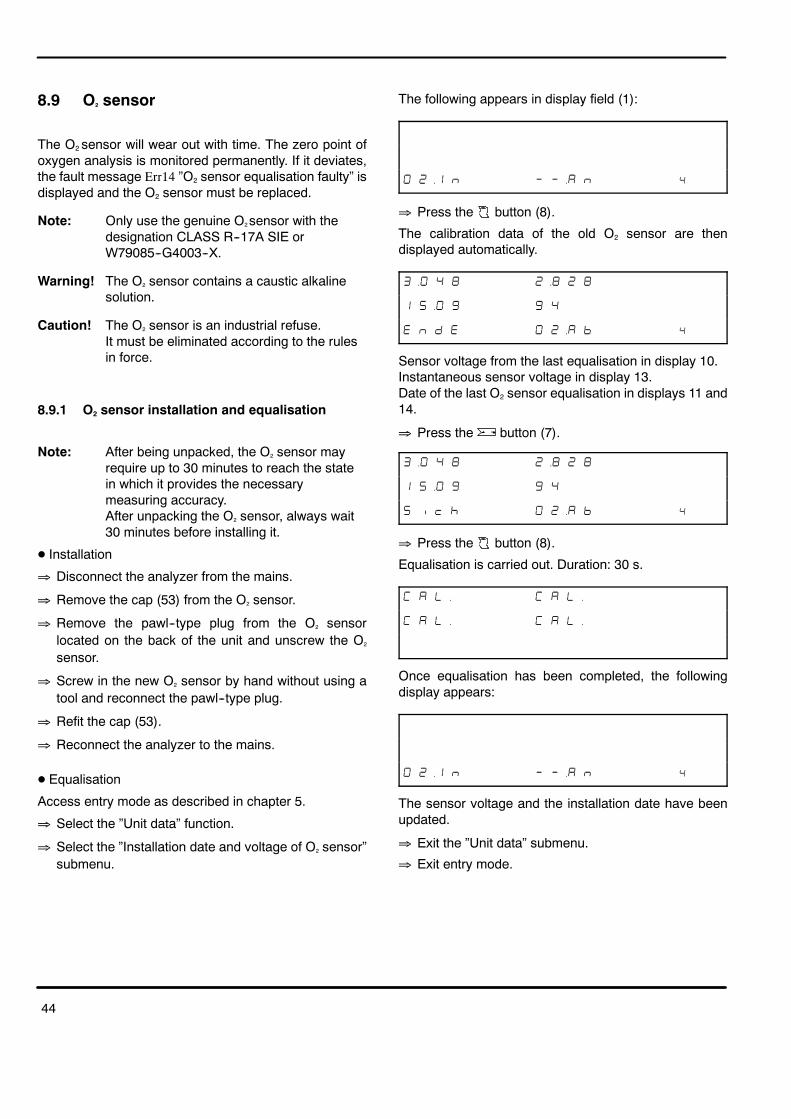
44
8.9 O2 sensor
The O2 sensor will wear out with time. The zero point ofoxygen analysis is monitored permanently. If it deviates,the fault message Err14 ”O2 sensor equalisation faulty” isdisplayed and the O2 sensor must be replaced.
Note: Only use the genuine O2sensor with thedesignation CLASS R--17A SIE orW79085--G4003--X.
Warning! The O2 sensor contains a caustic alkalinesolution.
Caution! The O2 sensor is an industrial refuse.It must be eliminated according to the rulesin force.
8.9.1 O2 sensor installation and equalisation
Note: After being unpacked, the O2 sensor mayrequire up to 30 minutes to reach the statein which it provides the necessarymeasuring accuracy.After unpacking the O2 sensor, always wait30 minutes before installing it.
D Installation
� Disconnect the analyzer from the mains.
� Remove the cap (53) from the O2 sensor.
� Remove the pawl--type plug from the O2 sensorlocated on the back of the unit and unscrew the O2
sensor.
� Screw in the new O2 sensor by hand without using atool and reconnect the pawl--type plug.
� Refit the cap (53).
� Reconnect the analyzer to the mains.
D Equalisation
Access entry mode as described in chapter 5.
� Select the ”Unit data” function.
� Select the ”Installation date and voltage of O2 sensor”submenu.
The following appears in display field (1):
��$ � � ��� � �
� Press the button (8).
The calibration data of the old O2 sensor are thendisplayed automatically.
�� � ��� � �
� � � �
� � � � ��� % �
Sensor voltage from the last equalisation in display 10.Instantaneous sensor voltage in display 13.Date of the last O2 sensor equalisation in displays 11 and14.
� Press the button (7).
�� � ��� � �
� � � �
� ' � ��� % �
� Press the button (8).
Equalisation is carried out. Duration: 30 s.
� � �� � � ��
� � �� � � ��
Once equalisation has been completed, the followingdisplay appears:
��$ � � ��� � �
The sensor voltage and the installation date have beenupdated.
� Exit the ”Unit data” submenu.
� Exit entry mode.

45
8.10 Recalibration with certificated testgas
The annual maintenance procedures cover the scope ofthe six--monthly procedures plus calibration with test gas.We recommend that you conclude a maintenanceagreement with your service agent.
When you conduct the annual inspection of the analyzerusing test gas, youmust use e.g. a cylinder of test gas thatcontains the certificated gas mixture of 3.5 % CO +14 % CO2 + 2000 ppm C3H8 (propane) in N2.
Warning! The test gas is odourless, combustibleand toxic!If you use a test gas cylinder with a cylinderpressure of greater than 0.7 bar, you mustattach a pressure--reducing valve (perDIN 477 for test gas under a pressure of≤ 4 bar) to the gas cylinder in order to pre--vent the analyzer from possible damage.
Caution! After a certain length of time (see thecertificate of the test gas), the test gas losesits accuracy. The test gas can no longer beused for calibration purposes once the datespecified has expired.
The service agency will parameterise the analyzer inaccordance with local regulations. To recalibrate theanalyzer, a test gas mixture is required that contains thefollowing concentrations (depending on requirements):
HC: 400 to 4000 ppm vol C3H8 (Propan)CO: 1 % vol to 10 % by volume of COCO2: 6 % vol to 18 % by volume of CO2
The test gasmust be fed into the test gas intake/gas outlet(41) via a viton hose at a rate of approximately 1 l/min. Theflow will be displayed.
Caution! The test gas hose must not be connected tothe analyzer until the analyzer indicates thatit is ready.
Select the AJ function as described in chapter 5.1 bypressing
� the button (9) or button (7).
� � � � � ��� � �
Activate the AJ function by pressing
� the button (8).
�
� � �� � ��� % �
Select the gas constituents to be set, e.g. target HC level,by pressing
� the button (9) or button (7).Activate the selected numbers for the HC target level bypressing
� the button (8).
�
� � � �
� � �� � ��� % �
Display value in ppm of C3H8 (propane).
Select the numbers to be set by pressing
� the button (9) or button (7).Activate the numbers by pressing
� the button (8).
�
� � �
� � �� � ��� % �
Amend the numbers by pressing
� the button (9) or button (7).Store the numbers set and return to number selection bypressing
� the button (8).
Once all the numbers have been set correctly, select the”End” function by pressing
� the button (9) or button (7).
�
� � � �
� � �� � ��� % �
Exit HC target level entry by pressing
� the button (8).
��
� # �� � ��� % �

� � � � � �
46
Select the next target level:proceed as for ”HC” above.Once all the levels have been set correctly, select ”i.0”from the menu by pressing
� the button (9) or button (7).All the target levels entered will be redisplayed.
� ��
� �
� ��� % �
Note: If you then press the button (8) toacknowledge the settings, recalibration willstart, for which you must use test gas.
� Press the button (8).
� � � � � �
� � � � � � �
�� �
The analyzer starts the warming--up period for test gascalibration.Note: The test gas hose must not yet be connected.System equalisation takes place at the end of thewarming--up period.
� � �� � � ��
� � �� � � ��
� � �� � � ��
� � �� � � ��
�
� Disconnect the gas outlet hose (41).� Connect the test gas hose.� Feed in the test gas.� The flow is displayed in the speed display field (12).
Set the flow to about 1 l/min.When the flow is sufficient, the measurements will bedisplayed and the flow will last 30 seconds.
� � ��
� � �
���
If one or more constituents of the gas deviate greatly fromthe target level set, the appropriate gas display will flashand ”Err” will appear in the oxygen display field.Calibration will be rejected.
� � � � �
���
When calibration has been properly completed, theanalyzer will return to entry mode.
� � � � � ��� � �
� Close off the test gas cylinder.
� Disconnect the test gas hose.
� Reconnect the gas outlet hose (41).

47
8.11 Standard parameterisation of theVAS 5067
The following parameters must be activated:
Entry mode parameters
-- Language �� (English)-- Printer �
-- Serial interface �%� ����
�%� ����
-- Serial protocol ��
Calibration parameters
-- HC test before every measurement-- Leak test interval 1 day-- Maintenance interval 183 days-- Calibration interval 365 days-- Calibration (test) gas mixture CO, HC, CO2
-- Change of settings parameter (�� & ���)

48
8.12 Service report
Service work
VAS 5067
Date Kind of work Company Name Signature

49
Date Kind of work Company Name Signature

50
9 Scope of delivery
The scope of delivery of the VAS 5067 comprises thefollowing:-- VAS 5067 basic unit-- Sampling probe, 400 mm long-- Sealing plug for leak test-- Gas sampling hose, 8 m Viton 5 x 1.5-- 3 PVC hoses, 0.7 m-- Filters-- Inductive clip--on pick up for engine--speedmeasurement
-- Mains supply cable-- 2 time--lag fuses, 0.8 A 250 V (spare)-- O2 sensor (integral)-- Operating instructions manual-- Connecting cable TD
10 Spare parts, parts subject towear and special accessories
Designation Part number
Sampling probe, 600 mm long C74211 A102 B55
Sealing plug for leak test-- O--ring seal for sealing plug
C79451 A3301 B345C71121 Z100 A60
Gas sampling hose,8 m Viton 5 x 1.5
C79451 A3407 C250
PVC hose set0.7 m 5 x 1.5
C79451 A3407 C252
Filter (e.g. GF1/2/3) C79127 Z400 A1
Activated charcoal filter C79127 Z1473 A1
O2 sensorCLASS R--17A SIE
W79085 64003 X
Oil temperature sensor-- Rubber cap with retaining spring
7MB1156 7AA08
Inductive trigger clamp--on pickup 7MB1156 7AA10
Connecting cable TD 7MB1156 7AA02
Internal protocol printer-- Paper roll-- Ribbon cassette
C75452 Z1 C1C79451 A3444 B312
Upgrade kit, second serial port C79451 A3407 D141

51
11 Technical data
Analysis Measurement range Resolution
CO meas. range 0,000-10.00 % vol CO 0,001 % vol
HC meas. range 0-9999 ppm vol HC 1 ppm vol
CO2 meas. range 0,00-18,00 % vol CO2 0,01 % vol
O2 meas. range 0,00-22,00 % vol O2 0,01 % vol
Lambda display 0,500-2,000 0,001
Speed measurement 0-9990 U/min 10 U/min
Oil temperature 0-150 _C 1 _C
Mains power supply 100 V, 120 V, 230 V, 240 Vselectable with bridges,50 or 60 Hz (setting byafter--sales service only)
Power input 110 V AElectromagneticcompatibility Class A as per EN 55 022Permissible ambienttemperature +2 �C bis +45 �CPermissible relativehumidity 5 % to 90 % without dew
Air pressure 700 hPa up to 1100 hPa(--300 m up to 2500 m altitude)
Normal position horizontal � 5�Height of installationlocation min. 250 mm from floor
(length of outlet hoses) min. 300 mmWarming--up time 3 minutesSystem equalisation 30 s, automatic, if requiredMeasurement gas flow 4 l/min
(min. 2 l/min, max. 6 l/min)Display delay < 15 s for 95 % measurement
accuracyWeight 10 kg
11.1 Temperature limits
Storing temperature --20 �C bis +65 �CContinuous load forviton hose andsampling probe 200 �C max.
Peak load forsampling probe 250 �C max. für < 3 min
11.2 Sound power level to DIN 45 635(in print mode)
Sound power level LWA 70,2 dBAEmission valueLpA at workplace 59,1 dBA
12 Guarantee
If any modifications are made to or non-genuineaccessories used with our products, all rights underguarantee shall be invalidated.
13 Service address
SIEMENS SPACentre Service Client1, chemin de la Sandlach
F--67506 Haguenau
Tel.: 0033 3 88 90 6677Fax: 0033 3 88 90 6688

52
E1998 VOLKSWAGEN AG, WolfsburgCustomer service/Garage Equipment/Sales All rights reserved
07/98Printed in France
(C79000--B5276--C183--02)AG 0798 52 En