vapor recovery & the capture of “associated gas' - …€¦ · · 2012-12-25pressure...
TRANSCRIPT

Vapor Recovery & The Capture of “Associated Gas”
Practical Applications & Case Studies
Rome 2008
Presented by:
Larry S. Richards
President & CEO
Hy-Bon Engineering Co.

““ASSOCIATED GASASSOCIATED GAS””
Storage TanksStorage Tanks
Production EquipmentProduction Equipment
CasingheadCasinghead GasGas

OIL STORAGE TANKSOIL STORAGE TANKS
Vapor RecoveryVapor Recovery
SystemsSystems


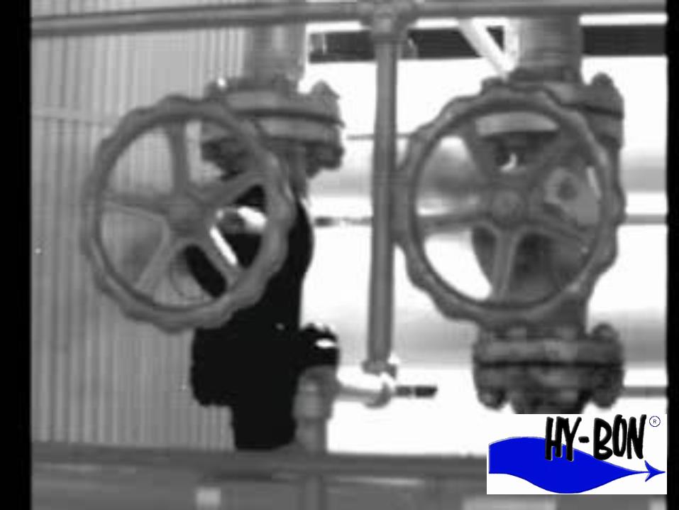
TANK OPERATIONSTANK OPERATIONS As the oilAs the oil resides inresides in the tanks, itthe tanks, it gives offgives off vapors,vapors, therebythereby increasingincreasing the pressurethe pressure inside theinside the tank.tank.

Sources of Methane LossesSources of Methane Losses
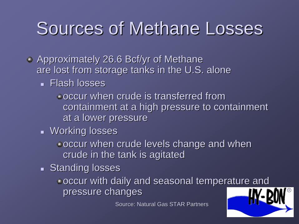
Approximately 26.6Approximately 26.6 BcfBcf/yr of Methane/yr of Methane are lost from storage tanks in the U.S. aloneare lost from storage tanks in the U.S. alone �� Flash lossesFlash losses
occur when crude is transferred fromoccur when crude is transferred from containment at a high pressure to containmentcontainment at a high pressure to containment at a lower pressureat a lower pressure
�� Working lossesWorking losses occur when crude levels change and whenoccur when crude levels change and when crude in the tank is agitatedcrude in the tank is agitated
�� Standing lossesStanding losses occur with daily and seasonal temperature andoccur with daily and seasonal temperature and pressure changespressure changes
Source: Natural Gas STSource: Natural Gas STAR PartnersAR Partners

WHY LET $ ESCAPE INTOWHY LET $ ESCAPE INTO THE AIR?THE AIR?
BesBesiidedess bebe iinng ang an environmentalenvironmental hazardhazard, escaping, escaping vapors result ivapors result inn ththe loss of ae loss of a major revenuemajor revenue sourcsourcee fofo r the oilr the oil company.company. Hundreds of oilHundreds of oil companies havecompanies have adadddeed significantd significant money to theirmoney to their bottom line bbottom line byy capturing thicapturing thiss valuvaluable gasable gas ststrreeam.am.
$$
$$ $$ $$ $$


VAPOR RECOVERY VAPOR RECOVERY SYSTEMSSYSTEMS

Standard Vapor Recovery UnitStandard Vapor Recovery Unit Vent Line
Back Pressure
Valve
Crude Oil Stock
Tank(s)
Control Pilot
Suction Scrubber
Suction Line
Condensate Return
Bypass Valve
Electric Control Panel
Electric Driven Rotary Compressor
Gas Sales Meter Run
Gas
Liquid Transfer Pump
Check Valve
Sales

VAPOR RECOVERYVAPOR RECOVERY Typical stockTypical stock tank vaportank vapor recovery unit inrecovery unit in operation.operation. ThisThis unit isunit is configured toconfigured to capture 90capture 90 mcfd of gmcfd of gaass and dischargeand discharge into a 40 psiginto a 40 psig sales line.sales line.

Benefits of Vapor RecoveryBenefits of Vapor Recovery UnitsUnits
Capture up to 95 percent ofCapture up to 95 percent of hydrocarbon vapors that accumulatehydrocarbon vapors that accumulate in tanksin tanks Recovered vapors have much higher BtuRecovered vapors have much higher Btu
content than pipeline quality natural gascontent than pipeline quality natural gas Recovered vapors can be more valuableRecovered vapors can be more valuable than methane alonethan methane alone Reduce regulatory & liability exposureReduce regulatory & liability exposure

Quantifying the Gas StreamQuantifying the Gas Stream
IDENTIFY emission sources using the FLIRIDENTIFY emission sources using the FLIR
GasFinderGasFinder cameracamera
QUANTIFYQUANTIFY emmissionsemmissions using chart, E&P Tank,using chart, E&P Tank,
HiFlowHiFlow Sampler, bagging techniques and actualSampler, bagging techniques and actual
tank tests per location with turbine meters,tank tests per location with turbine meters,
recording manometers and mass flow meters.recording manometers and mass flow meters.
RECTIFY emission by recommending bestRECTIFY emission by recommending best
technical alternatives available in the industry fortechnical alternatives available in the industry for
capturing each source and adding to thecapturing each source and adding to the
revenue streamrevenue stream

Estimated Volume of TankEstimated Volume of Tank V
apor
Ven
ted
frV
apor
Ven
ted
fr om
Tan
ksom
Tan
ks-- S
CF/
BBL
SCF/
BBL
-- GO
RG
OR
VaporsVapors 110110
100100
9090
8080
7070
6060
5050
4343
4040
3030
2020
1010
Under 30Under 30°° APIAPI
3030°° API to 39API to 39°° APIAPI4040°° API and Over
API and Over
1010 2020 3030 4040 5050 6060 7070 8080
Pressure of Vessel Dumping to TankPressure of Vessel Dumping to Tank (Psig)(Psig)

Estimating Tank EmissionsEstimating Tank Emissions Chart method is a quick and easy way to getChart method is a quick and easy way to get
a fast ballpark estimatea fast ballpark estimate
Notice the impact of higher gravity oil, as wellNotice the impact of higher gravity oil, as well as higher separator pressuresas higher separator pressures
This method is VERY CONSERVATIVE andThis method is VERY CONSERVATIVE and generally underestimates actual emissiongenerally underestimates actual emission levelslevels

Quantify Volume of LossesQuantify Volume of Losses
E&P TankE&P Tank ModelModel �� Computer software developed by APIComputer software developed by API
and GRIand GRI �� Estimates flash, working, and standing lossesEstimates flash, working, and standing losses �� Calculates losses using specific operatingCalculates losses using specific operating
conditions for each tankconditions for each tank �� Provides composition of hydrocarbon lossesProvides composition of hydrocarbon losses

E&P TANK INPUT SCREENE&P TANK INPUT SCREEN


E&P TANK EXAMPLEE&P TANK EXAMPLE
OUTPUTOUTPUT
0.003 0.219 0.000
16.262
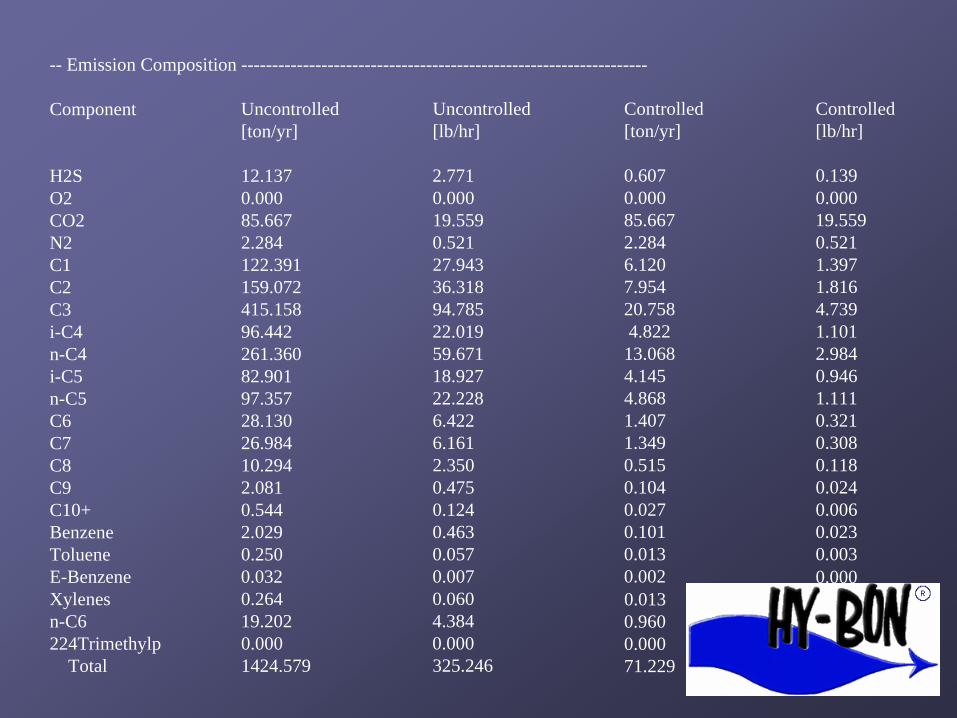
-- Emission Composition ------------------------------------------------------------------
Component
H2S O2 CO2 N2 C1 C2 C3 i-C4 n-C4 i-C5 n-C5 C6 C7 C8 C9 C10+ Benzene Toluene E-Benzene Xylenes n-C6 224Trimethylp
Total
Uncontrolled [ton/yr]
12.137 0.000 85.667 2.284 122.391 159.072 415.158 96.442 261.360 82.901 97.357 28.130 26.984 10.294 2.081 0.544 2.029 0.250 0.032 0.264 19.202 0.000 1424.579
Uncontrolled [lb/hr]
2.771 0.000 19.559 0.521 27.943 36.318 94.785 22.019 59.671 18.927 22.228 6.422 6.161 2.350 0.475 0.124 0.463 0.057 0.007 0.060 4.384 0.000 325.246
Controlled Controlled [ton/yr] [lb/hr]
0.607 0.139 0.000 0.000 85.667 19.559 2.284 0.521 6.120 1.397 7.954 1.816 20.758 4.739 4.822 1.101
13.068 2.984 4.145 0.946 4.868 1.111 1.407 0.321 1.349 0.308 0.515 0.118 0.104 0.024 0.027 0.006 0.101 0.023 0.013 0.003 0.002 0.000 0.013 0.960 0.000 71.229

-- Emission Summary ----------------------------------------------------------------------Item Uncontrolled Uncontrolled Controlled Controlled
[ton/yr] [lb/hr] [ton/yr] [lb/hr]
Total HAPs 21.780 4.973 1.089 0.249 Total HC 1324.491 302.395 66.225 15.120 VOCs, C2+ 1202.100 274.452 60.105 13.723 VOCs, C3+ 1043.029 238.134 52.151 11.907
Uncontrolled Recovery Info.
Vapor 71.3400 [MSCFD] HC Vapor 66.3900 [MSCFD]
GOR 35.67 [SCF/bbl]

TANK TESTTANK TEST
A chart recorder is set up on the tank battery for a 24-hour pressure test. The resultant chart is brought into the office for evaluation. Information such as ambient temperature, test apparatus size and orifice size is recorded and used in the calculation of volume of tank vapors.
TANK TESTTANK TEST Ultrasonic meters, Turbine meters and Mass flow meters are also highly effective
The key is DURATION – a minimum of
24 hours of emissions must be charted
for accurate results

CASE STUDIESCASE STUDIES &&
EXAMPLESEXAMPLES

Industry Experience: OxyIndustry Experience: Oxy Oxy Case StudyOxy Case Study -- Vapor RecovVapor Recoveeryry Wasson TankWasson Tank Battery (CDU 1 & 2)Battery (CDU 1 & 2) Denver City,Denver City, TexasTexas Installed in 2004Installed in 2004
Oxy purchased two vapor recoveryOxy purchased two vapor recovery units in August 2004 for capturunits in August 2004 for capturinging vapors from two separate tank bavapors from two separate tank batteries at their Wasson facilitytteries at their Wasson facility..
Each battery produces approximatelyEach battery produces approximately 450 MCFD of tank vapors,450 MCFD of tank vapors, whiwhich Oxych Oxy needed to gather and compressneeded to gather and compress into a 45 psig sales line.into a 45 psig sales line.
Due to the low discharge pressure, Oxy selected rotary vane compDue to the low discharge pressure, Oxy selected rotary vane compressorressor packages capable of moving 500 MCFD.packages capable of moving 500 MCFD.
In order toIn order to minimize maintenanceminimize maintenance, Oxy selected electric drive un, Oxy selected electric drive unitsits (75 horsepower electric motors on each unit).(75 horsepower electric motors on each unit).
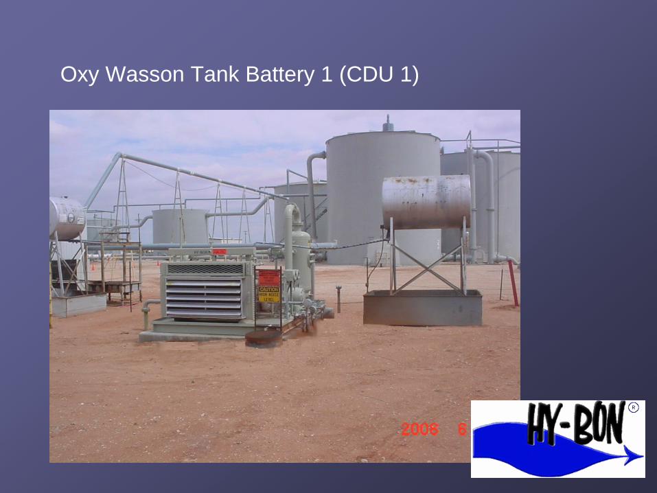
Oxy Wasson Tank Battery 1 (CDU 1)

Oxy Wasson Tank Battery 2 – CDU2

Industry Experience: OxyIndustry Experience: Oxy
Purchase CostPurchase Cost Installation CostInstallation Cost Installed CostInstalled Cost Gas Volume (mcfd)Gas Volume (mcfd) Value @ $6 / mcfValue @ $6 / mcf Annual RevenueAnnual Revenue (with NO(with NO btubtu adjustmentadjustment and no liquid sales)and no liquid sales) Monthly Incr. RevenueMonthly Incr. Revenue Payout (in Months)Payout (in Months)
$92,500$92,500
$9,500$9,500 $102,000$102,000
450450 $2,700$2,700
$985,500$985,500
$82,125$82,125
1.241.24
$185,000$185,000
$19,000$19,000
$204,000$204,000
900900 $5,400$5,400
$1,971,000$1,971,000
$164,250$164,250
1.241.24

This is one of 3 Vapor Recovery Units that will be used to capture 25 Million cubic feet of gas in Angola for the Chevron Cabinda project – commissions in 2008.

Installed November 2007Installed November 2007
AngolaAngola
Chevron Cabinda FlareChevron Cabinda Flare
Reduction ProjectReduction Project -- 2525
MMCFDMMCFD


Project OverviewProject Overview –– ChevronChevron Cabinda Project (Angola)Cabinda Project (Angola)
This project was the ChevronThis project was the Chevron’’s largest flares largest flare reduction project in 2007reduction project in 2007 –– Angola CabindaAngola Cabinda HyHy--Bon Vapor Recovery Units are scheduled toBon Vapor Recovery Units are scheduled to be commissioned in Fall 2008.be commissioned in Fall 2008. The 25 MMCFD of flare and vent gas recoveredThe 25 MMCFD of flare and vent gas recovered has the same greenhouse gas effect ofhas the same greenhouse gas effect of removing 812,000 cars from the road or plantingremoving 812,000 cars from the road or planting 1.1 million acre of trees1.1 million acre of trees

Project OverviewProject Overview -- PDVSaPDVSa
This flare in VenezuelaThis flare in Venezuela was causing a varietywas causing a variety of healof health andth and environmentalenvironmental concerns.concerns. Billions ofBillions of cubic fcubic feet of methaneeet of methane are vented and flaredare vented and flared from oilfrom oilffield separaield separatorstors and sand sttorage taorage tanks innks in almosalmostt everyevery producingproducing country.country.

Project OverviewProject Overview -- PDVSaPDVSa
This dual flooded screw package for PDVSA is
designed for volumes to 5.0 MMSCFD; moving tank
vapors from 0 to 200 psig in Eastern Venezuela.

Project OverviewProject Overview -- PDVSaPDVSa
At this location, three of our compressor packages
were set in tandem to move 15 MMSCFD of 2500-2600
BTU tank vapors.
Project OverviewProject Overview –– PDVSaPDVSa GasGas AnacoAnaco (Venezuela)(Venezuela)
Vapor recovery units currently capture over 75Vapor recovery units currently capture over 75 million cubic feet of previously vented and flaredmillion cubic feet of previously vented and flared gas across 7 facilitiesgas across 7 facilities GasGas AnacoAnaco project, begun in 2006, targets overproject, begun in 2006, targets over one billion cubic feet of gas across easternone billion cubic feet of gas across eastern VenezuelaVenezuela Conversion of much of the power andConversion of much of the power and transportation infrastructure to natural gas istransportation infrastructure to natural gas is underwayunderway

EniEni DacionDacion
Eni installed vapor recovery
systems in their Dacion East and
West facilities in Venezuela, each
designed to move 1.4 MMSCFD
of gas at pressures to 230 psig.
Eni Oil & Gas
Dacion Field, Venezuela
2004

Project OverviewProject Overview –– EniEni DacionDacion (Venezuela)(Venezuela)
Vapor recovery units were installed to captureVapor recovery units were installed to capture up to 1.4 MMCFD per siteup to 1.4 MMCFD per site White paper was written shortly after installationWhite paper was written shortly after installation on the economic success of the projecton the economic success of the project A highly valuable 70 API gravity condensate wasA highly valuable 70 API gravity condensate was recovered from the gas stream and used torecovered from the gas stream and used to blend with the primary low API gravity oilblend with the primary low API gravity oil productionproduction –– at an approximate daily rate of 100at an approximate daily rate of 100 to 150 barrels of condensate per unit.to 150 barrels of condensate per unit.

M2M Project UpdateM2M Project Update
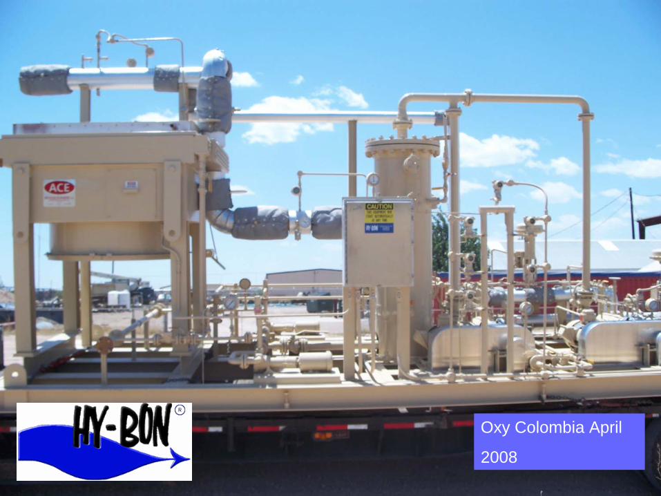
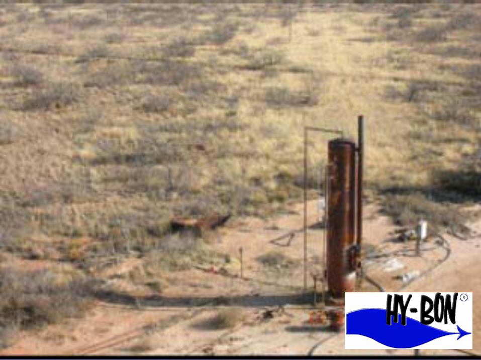
Oxy ColombiaOxy Colombia

Initial project will be capturing approximately 350 mcfd of vent gas from the Caricare oil storage and production facility.
Purpose of the project will be incremental capture of natural gas liquids from this gas stream.
Two additional sites are planned following successful installation of the first project.
Subsequent project to utilize flare gas is also being evaluated by Oxy Colombia.
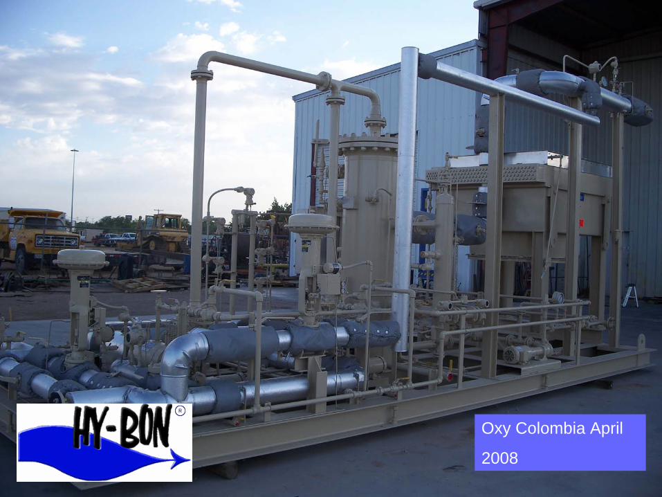
Oxy Colombia April
2008
Oxy Colombia April
2008

Oxy Colombia April
2008

Other Emission SourcesOther Emission Sources
Gas can also beGas can also be captured fromcaptured from separators andseparators and other fieldother field equipment.equipment. This unit isThis unit is capturing naturalcapturing natural gas off severalgas off several separators forseparators for sale down a highsale down a high pressure line.pressure line.
oror
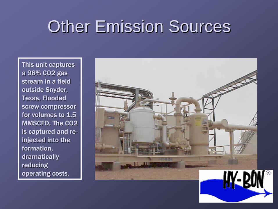
Other Emission SourcesOther Emission Sources This unit capturesThis unit captures a 98% CO2 gasa 98% CO2 gas stream in a fieldstream in a field outside Snyder,outside Snyder, Texas. FloodedTexas. Flooded screw compressorscrew compressor for volumes to 1.5for volumes to 1.5 MMSCFD. The CO2MMSCFD. The CO2 is captured and reis captured and re--injected into theinjected into the formation,formation, dramaticallydramatically reducingreducing operating costs.operating costs.
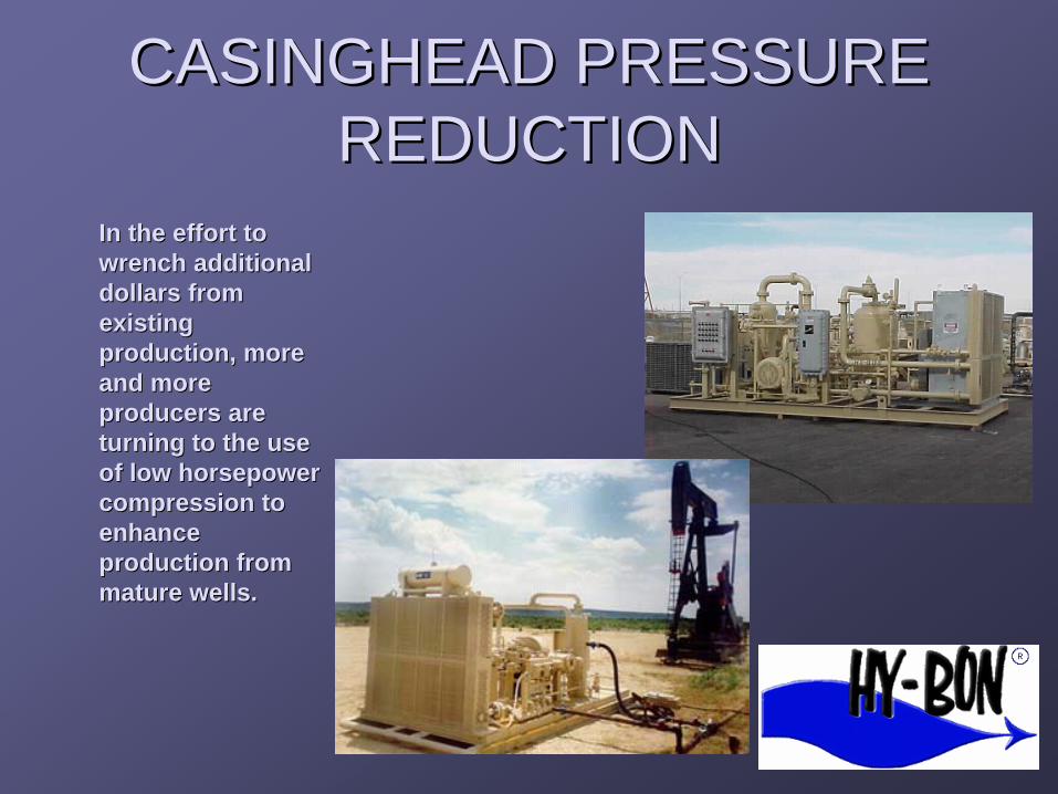
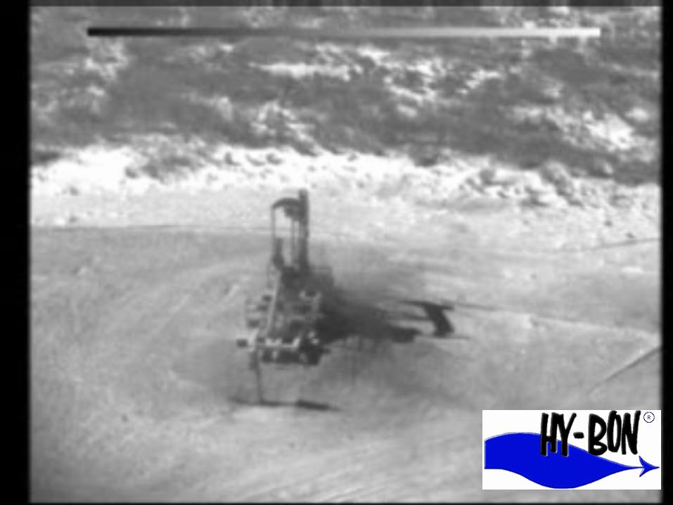
CASINGHEAD PRESSURECASINGHEAD PRESSURE REDUCTIONREDUCTION
In the eIn the effort toffort to wrench additionalwrench additional dollars fromdollars from existingexisting production, moreproduction, more and moreand more producers areproducers are turning to the useturning to the use of low horsepowerof low horsepower compression tocompression to eennhahancence production fromproduction from mature wellsmature wells..
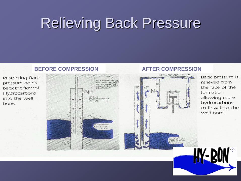
Relieving Back PressureRelieving Back Pressure
BEFORE COMPRESSION AFTER COMPRESSION

yy

Casinghead gas is usually piped 30 to 90 feet from the wellhead and quietly vented to atmosphere
Casinghead gas is vented in almost every oil producing country

MultipleMultiple CasingheadCasinghead PressurePressure
Reduction Case Studies and 2Reduction Case Studies and 2
published articles available atpublished articles available at
www.hywww.hy--bon.combon.com

In ConclusionIn Conclusion ……
HydrocarbonHydrocarbon ““Spills in the AirSpills in the Air””
ShareholderShareholder ““Lost ProductLost Product””
Truly Unique OpportunityTruly Unique Opportunity

HYHY--BON ENGINEERINGBON ENGINEERING COMPANY, INC.COMPANY, INC.
Setting a New Standard!!Setting a New Standard!!
www.hy-bon.com