valves, air preparation we make equipment & actuators catalog · our range of high-performance...
TRANSCRIPT

Valves, Air Preparation Equipment & Actuators Catalog
We make things MOVE®

BIMBA BIM-VAPA-0419 Catalog 2019 | For Technical Assistance: 800-442-4622
2
We Make Things Move®
A forward-thinking innovator, Bimba provides industry-leading pneumatic, hydraulic and electric motion solutions that are easy-to-use, reliable and ready for your engineering challenges.
Doing whatever it takes to help you get the job done is what the Bimba companies do best. With an extensive line of industry-leading air cylinders, rotary actuators, linear thrusters, rodless cylinders, NFPA, hydraulics, flow controls, position-sensing cylinders, valves, switches and air preparation equipment, the people of Bimba are ready to tackle your toughest applications.
Bimba is part of IMI Precision Engineering, a world leader in motion and fluid control technologies. Wherever precision, speed and engineering reliability are essential, we deliver exceptional solutions which improve the productivity and efficiency of customers’ equipment.
Our range of high-performance products, such as actuators, valves, valve islands, pressure monitoring controls and air preparation products together with trusted products brands including IMI Norgren, IMI Buschjost, IMI FAS, IMI Herion and IMI Maxseal underpin our position as a leading global supplier.
Part of IMI plc, we have a sales and service network in 75 countries, as well as manufacturing capability in the USA, Germany, China, UK, Switzerland.
Contents
02 Introduction
03 Valves
39 Air Preparation Equipment
81 Actuators

BIMBA BIM-VAPA-0419 Catalog 2019 | For Technical Assistance: 800-442-4622
3
Control your media flow with Bimba’s valves and valve accessories selection. Our line of compact, cost-effective valves covers a wide variety of unique applications, from standard solenoid and air pilot valves, to manually operated hand valves and explosion-proof options.
Valves
Contents
5 M3V1 Series Solenoid Valves 5 – Engineering Specifications 6 – Stacking Assembly & Dimensions 7 – How To Order
8 M3V Series Solenoid Valves 8 – Engineering Specifications 9 – Dimensions 10 – How To Order
11 M4V Series Solenoid Valves 11 – Engineering Specifications 12 – Dimensions 14 – How To Order
15 Manifolds for M3V Series Valves 15 – Engineering Specifications 16 – How To Order
17 Manifolds for M4V Series Valves 17 – Engineering Specifications 18 – How To Order
19 MPS Series 19 – Engineering Specifications 19 – Dimensions & Wiring Diagram 19 – Accessories 20 – How To Order
21 Manifold Powerstrip™ Selection Guide 21 – How To Order
22 M4M (Namur) Series Solenoid Valves 22 – Engineering Specifications 22 – Dimensions 23 – How To Order
24 Explosion Proof Coils 24 – Engineering Specifications 25 – Solenoid Valve Coils & Connectors 25 – Wiring Diagram
26 M4A Series Air Pilot Valves 26 – Engineering Specifications 27 – Dimensions 28 – How To Order
29 M4H Series Hand Lever Valves 29 – Engineering Specifications 29 – Dimensions & Installation Options 30 – How To Order
31 M4HV Series Hand Lever Valves 31 – Engineering Specifications 31 – Dimensions 32 – How To Order
33 M4L Series Push-Pull Valves 33 – Engineering Specifications 33 – Dimensions 34 – How To Order
35 M4F Series Foot Pedal Valves 35 – Engineering Specifications 35 – Dimensions 36 – How To Order
37 MASC Series Flow Control 37 – Dimensions 38 – How To Order
BIMBA BIM-VAPA-0419 Catalog 2019 | For Technical Assistance: 800-442-4622
5
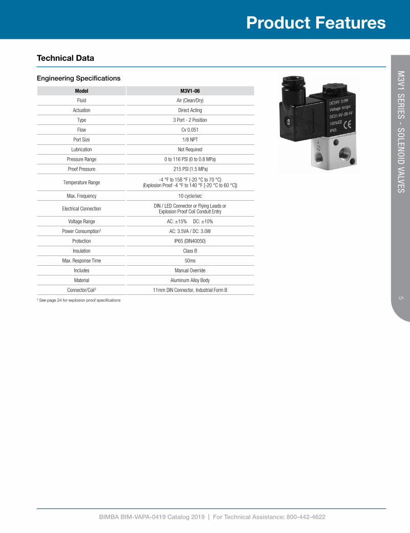
Model M3V1-06
Fluid Air (Clean/Dry)
Actuation Direct Acting
Type 3 Port - 2 Position
Flow Cv 0.051
Port Size 1/8 NPT
Lubrication Not Required
Pressure Range 0 to 116 PSI (0 to 0.8 MPa)
Proof Pressure 215 PSI (1.5 MPa)
Temperature Range -4 °F to 158 °F (-20 °C to 70 °C)(Explosion Proof -4 °F to 140 °F [-20 °C to 60 °C])
Max. Frequency 10 cycle/sec
Electrical Connection DIN / LED Connector or Flying Leads or Explosion Proof Coil Conduit Entry
Voltage Range AC: ±15% DC: ±10%
Power Consumption3 AC: 3.5VA / DC: 3.0W
Protection IP65 (DIN40050)
Insulation Class B
Max. Response Time 50ms
Includes Manual Override
Material Aluminum Alloy Body
Connector/Coil3 11mm DIN Connector, Industrial Form B
3 See page 24 for explosion proof specifications
Product Features
Technical Data
Engineering Specifications
M3V1 SERIES - SO
LENO
ID VALVES

BIMBA BIM-VAPA-0419 Catalog 2019 | For Technical Assistance: 800-442-4622
6
M3V1-P32
M3V1-P32 M3V1-P31
M3V1-P30
M3V1-P31
M3V1 STACK - CATALOGTHIS DRAWING CONTAINS PROPRIETARY DESIGNS AND/OR INFORMATION OF BIMBA MFG. CO. OR ITS SUBSIDIARIES AND IS NOT TO
BE TRANSMITTED, REPRODUCED, USED OR DISCLOSED WITHOUT WRITTEN PERMISSION OF BIMBA MFG. CO. OR ITS SUBSIDIARIES. DESIGN REFLECTS OUR BEST ENGINEERING OPINION BASED ON WRITTEN APPLICATION SPECIFICATIONS RECEIVED. SUITABILITY OF A
DESIGN FOR AN APPLICATION REQUIRES ANALYSIS AND/OR TESTS IN YOUR SPECIFIC SYSTEM.
Mead Fluid Dynamics, Inc.Chicago, IL. 60641
(877) MEAD USA [email protected]
PROPRIETARY DRAWING - Reference Only
Note: Stacking Assembly not compatible with Explosion Proof coils
How To Specify
Part Number Description
M3V1-P30 Stack Starting Kit
M3V1-P31 Stack Coupling Kit
M3V1-P32 Mounting Bracket Kit
Product Information
13 40
63.5
18
3.5 10.5 5.5
16
30
(2) 3.3 THRU
62
76
23
8
(3) 1/8 NPT PORTS
MANUALOVERRIDE
(2)M4 X 0.76
25
15
13 40
63.5
18
3.5 10.5 5.5
16
30
(2) 3.3 THRU
62
76
23
8
(3) 1/8 NPT PORTS
MANUALOVERRIDE
(2)M4 X 0.76
25
15
Stacking Assembly
Dimensions (mm)
M3V1 SERIES - SO
LENO
ID VALVES

BIMBA BIM-VAPA-0419 Catalog 2019 | For Technical Assistance: 800-442-4622
7
How To Order
How To Order
PR
A
1 Not available with 24VAC. Flying Leads are 300mm long.2 See page 24 for specifications. Leads are 580mm long.
M3V1-06-24VDC-XProduct Line
M3V1 Series
Voltage
12VDC
24VDC
24VAC 50/60 Hz
120VAC 50/60 Hz
Electrical Connection
Blank = DIN Connector
FL = Flying Leads1
X = Explosion Proof2
Port Size
06 = 1/8 NPT
M3V1 SERIES - SO
LENO
ID VALVES
BIMBA BIM-VAPA-0419 Catalog 2019 | For Technical Assistance: 800-442-4622
8
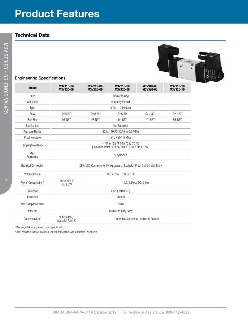
1 See page 24 for explosion proof specifications
Note: Manifold (shown on page 15) not compatible with Explosion Proof coils
Model M3V110-06 M3V120-06
M3V210-06 M3V220-06
M3V210-08 M3V220-08
M3V310-08 M3V320-08
M3V310-10 M3V320-10
Fluid Air (Clean/Dry)
Actuation Internally Piloted
Type 3 Port - 2 Position
Flow Cv 0.67 Cv 0.78 Cv 0.89 Cv 1.39 Cv 1.67
Port Size 1/8 NPT 1/8 NPT 1/4 NPT 1/4 NPT 3/8 NPT
Lubrication Not Required
Pressure Range 22 to 116 PSI (0.15 to 0.8 MPa)
Proof Pressure 215 PSI (1.5 MPa)
Temperature Range -4 °F to 158 °F (-20 °C to 70 °C) [Explosion Proof -4 °F to 140 °F (-20 °C to 60 °C])
Max. Frequency 5 cycle/sec
Electrical Connection DIN / LED Connector or Flying Leads or Explosion Proof Coil Conduit Entry
Voltage Range AC: ±15% DC: ±10%
Power Consumption1 AC: 2.5VA / DC: 2.5W AC: 3.5VA / DC: 3.0W
Protection IP65 (DIN40050)
Insulation Class B
Max. Response Time 50ms
Material Aluminum Alloy Body
Connector/Coil1 9.4mm DIN, Industrial Form C 11mm DIN Connector, Industrial Form B
Technical Data
Engineering Specifications
Product Features
M3V SERIES - SO
LENO
ID VALVES

BIMBA BIM-VAPA-0419 Catalog 2019 | For Technical Assistance: 800-442-4622
9
How To Specify
Product Information
Dimensions (mm) – Single Solenoid
Dimensions (mm) – Double Solenoid
W
P
R
S T
U
V
Y G
L
M N
C
E
D
Model A C D E G L M N P R S T U V WM3V110-06 16 14.7 18 7.7 3.1 34 3.3 88.4 13
16.7 0 3 40 66.7 30 3.3 170 3 40 66.7 30 3.3 17
M3V310-08 0 30 40 4.3 40 4.3M3V310-10 0 30 40 4.3 40 4.3
M3V Single Solenoid SeriesTHIS DRAWING CONTAINS PROPRIETARY DESIGNS AND/OR INFORMATION OF BIMBA MFG. CO. OR ITS SUBSIDIARIES AND IS NOT TO
BE TRANSMITTED, REPRODUCED, USED OR DISCLOSED WITHOUT WRITTEN PERMISSION OF BIMBA MFG. CO. OR ITS SUBSIDIARIES. DESIGN REFLECTS OUR BEST ENGINEERING OPINION BASED ON WRITTEN APPLICATION SPECIFICATIONS RECEIVED. SUITABILITY OF A
DESIGN FOR AN APPLICATION REQUIRES ANALYSIS AND/OR TESTS IN YOUR SPECIFIC SYSTEM.
Mead Fluid Dynamics, Inc.Chicago, IL. 60641
(877) MEAD USA [email protected]
PROPRIETARY DRAWING - Reference Only
Model A B C D E F G H J K L M N P R S T U V W Y
M3V110-06 1/8 NPT 16 14.7 2 18 21 12.2 27 7.7 3.1 2.5 34 55 1/8 NPT 19 13.2 23.7 3.3 88.4 13 1
M3V210-06 1/8 NPT 22 16.7 0 22 25 15.2 35 8.2 4.2 3 40 67 1/8 NPT 30 12.7 27.7 3.3 109 17 0
M3V210-08 1/4 NPT 22.5 16.5 0 22 25 15.2 35 8.2 4.2 3 40 67 1/4 NPT 30 12.7 28.7 3.3 109 17 1.5
M3V310-08 1/4 NPT 24 20.5 0 27 30 17.5 40 10.5 4.3 2.4 40 69 1/4 NPT 35 15 32.5 4.3 120 20 0
M3V310-10 3/8 NPT 24 20.5 0 27 30 17.5 40 10.5 4.3 2.4 40 69 3/8 NPT 35 15 32.5 4.3 120 20 2
P
R
S T
V
W
(2) U
Y
F
G
H
J
(2) K
L
M N
(2)A
B
C
E
D
Model A B C D E F G H J K L M N P R S T U V WM3V120-06 1/8 NPT 16 57.7 2 18 21 55.2 27 7.7 3.1 2.5 34 55 1/8 NPT 19 56.2 66.7 3.3 131.4 13M3V220-06 1/8 NPT 22 70.4 0 22 25 69 35 8.2 4.2 3 40 66.7 1/8 NPT 30 66.4 81.4 3.3 162.8 17M3V220-08 1/4 NPT 22.5 70.2 0 22 25 69 35 8.2 4.2 3 40 66.7 1/4 NPT 30 66.4 82.4 3.3 162.8 17M3V320-08 1/4 NPT 24 75.4 0 27 30 724. 40 10.5 4.3 2.4 40 69.2 1/4 NPT 35 70 87.4 4.3 174.8 20M3V320-10 3/8 NPT 24 75.4 0 27 30 72.4 40 10.5 4.3 2.4 40 69.2 3/8 NPT 35 70 87.4 4.3 174.8 20
Model A B C D E F G H J K L M N P R S T U V W Y
M3V120-06 1/8 NPT 16 57.7 2 18 21 55.2 27 7.7 3.1 2.5 34 55 1/8 NPT 19 56.2 66.7 3.3 131.4 13 1
M3V220-06 1/8 NPT 22 70.4 0 22 25 69 35 8.2 4.2 3 40 67 1/8 NPT 30 66.4 81.4 3.3 162.8 17 0
M3V220-08 1/4 NPT 22.5 70.2 0 22 25 69 35 8.2 4.2 3 40 67 1/4 NPT 30 66.4 82.4 3.3 162.8 17 1.5
M3V320-08 1/4 NPT 24 75.4 0 27 30 72.4 40 10.5 4.3 2.4 40 69 1/4 NPT 35 70 87.4 4.3 174.8 20 0
M3V320-10 3/8 NPT 24 75.4 0 27 30 72.4 40 10.5 4.3 2.4 40 69 3/8 NPT 35 70 87.4 4.3 174.8 20 2
M3V SERIES - SO
LENO
ID VALVES

BIMBA BIM-VAPA-0419 Catalog 2019 | For Technical Assistance: 800-442-4622
10
How To Order
How To Order
A
P R
10-NC
A
P R20
M3V 2 10-08-NC-24VDC-XProduct Line
M3V Series
Voltage
12VDC
24VDC
24VAC 50/60 Hz
120VAC 50/60 Hz
Type
10 = Single Solenoid
20 = Double SolenoidModel
1 = 100 Series
2 = 200 Series
3 = 300 Series
2 Not available with 100 series 24VAC. Flying Leads are 300mm long.3 See page 24 for specifications. Leads are 580mm long.
Electrical Connection
Blank = DIN Connector
FL = Flying Leads2
X = Explosion Proof3Port Size
06 = 1/8 NPT (100, 200 Series)
08 = 1/4 NPT (200, 300 Series)
10 = 3/8 NPT (300 Series)
Operation1
NC = Normally1 Required for Single Solenoid only
M3V SERIES - SO
LENO
ID VALVES

BIMBA BIM-VAPA-0419 Catalog 2019 | For Technical Assistance: 800-442-4622
11
Product Features
Technical Data
Model M4V110-06 M4V120-06
M4V130C-06 M4V130E-06
M4V210-06 M4V220-06
M4V230C-06 M4V230E-06
M4V210-08 M4V220-08
M4V230C-08M4V230E-08
Fluid Air (Clean/Dry)
Actuation Internally Piloted
Type 5 Port-2 Position 5 Port-3 Position 5 Port-2 Position 5 Port-3 Position 5 Port-2 Position 5 Port-3 Position
Flow Cv 0.67 Cv 0.50 Cv 0.78 Cv 0.67 Cv 0.89 Cv 0.67
Port Size 1/8 NPT 1/8 NPT Inlet/Outlet Ports 1/4 NPT Exhaust Ports 1/8 NPT
Lubrication Not Required
Pressure Range 22 to 116 PSI (0.15 to 0.8 MPa)
Proof Pressure 215 PSI (1.5 MPa)
Temperature Range -4 °F to 158 °F (-20 °C to 70 °C) (Explosion Proof -4 °F to 140 °F ([20 °C to 60 °C])
Max. Frequency 5 cycle/sec 3 cycle/sec 5 cycle/sec 3 cycle/sec 5 cycle/sec 3 cycle/sec
Electrical Connection DIN / LED Connector or Flying Leads or Explosion Proof Coil Conduit Entry
Voltage Range AC: ±15% DC: ±10%
Power Consumption1 AC: 2.5VA / DC: 2.5W AC: 3.5VA / DC: 3.0W
Protection IP65 (DIN40050)
Insulation Class B
Max. Response Time 50ms
Material Aluminum Alloy Body
Connector/Coil1 9.4mm DIN, Industrial Form C 11mm DIN Connector, Industrial Form B
Engineering Specifications
1 See page 24 for explosion proof specifications
Note: Manifold (shown on page 17) not compatible with Explosion Proof coils
Model M4V310-08 M4V320-08
M4V330C-08 M4V330E-08
M4V310-10 M4V320-10
M4V330C-10 M4V330E-10
M4V410-15 M4V420-15
M4V430C-15 M4V430E-15
Fluid Air (Clean/Dry)
Actuation Internally Piloted
Type 5 Port-2 Position 5 Port-3 Position 5 Port-2 Position 5 Port-3 Position 5 Port-2 Position 5 Port-3 Position
Flow Cv 1.40 Cv 1.00 Cv 1.68 Cv 1.00 Cv 2.79 Cv 1.68
Port Size 1/4 NPT Inlet/Outlet Ports 3/8 NPTExhaust Ports 1/4 NPT 1/2 NPT
Lubrication Not Required
Pressure Range 22 to 116 PSI (0.15 to 0.8 MPa)
Proof Pressure 215 PSI (1.5 MPa)
Temperature Range -4 °F to 158 °F (-20 °C to 70 °C) (Explosion Proof -4 °F to 140 °F (-20 °C to 60 °C))
Max. Frequency 4 cycle/sec 3 cycle/sec 4 cycle/sec 3 cycle/sec 3 cycle/sec
Electrical Connection DIN / LED Connector or Flying Leads or Explosion Proof Coil Conduit Entry
Voltage Range AC: ±15% DC: ±10%
Power Consumption1 AC: 3.5VA / DC: 3.0W
Protection IP65 (DIN40050)
Insulation Class B
Max. Response Time 50ms
Material Aluminum Alloy Body
Connector/Coil1 11mm DIN Connector, Industrial Form B
M4V SERIES - SO
LENO
ID VALVES

BIMBA BIM-VAPA-0419 Catalog 2019 | For Technical Assistance: 800-442-4622
12
How To Specify
Product Information
MODEL A B C D E F G H J K L
M4V110-06 1/8 NPT 28 14.2 13 18 28.2 70.4 14 21.2 9.5 27
M4V210-06 1/8 NPT 36 13.7 17 22 31.7 81 20 21.7 10.5 35
M4V210-08 1/8 NPT 36 13.7 17 22 31.7 81 20 21.7 10.5 35
M4V310-08 1/4 NPT 45 17.5 20 27 40 98.7 24 28 13.5 40
M4V310-10 1/4 NPT 45 17.5 20 27 40 98.7 24 28 13.5 40
M4V410-15 1/2 NPT 63 25.5 27 34 57 132.3 28 43 17.5 50
G
J
L
R
P
K
N
M
(2) S
H
(3) T
U
V W
X
Y
(2) Z
AA
B
C F
(2) A
E
D
Model A B C D E F G H J K L M N P R S T U V W X Y Z AAM4V110-06 1/8 NPT 28 14.2 13 18 28.2 70.4 14 21.2 9.5 27 59.4 2.5 34 55 3.3 1/8 NPT 30 13.2 3 20.2 16 3.3 99.4M4V210-06 1/8 NPT 36 13.7 17 22 31.7 81 20 21.7 10.5 35 62 3 40 66.7 4.3 1/8 NPT 38 12.7 0 22.7 18 3.2 117.1M4V210-08 1/8 NPT 36 13.7 17 22 31.7 81 20 21.7 10.5 35 62 3 40 66.7 4.3 1/4 NPT 38 12.7 3 21.2 21 3.2 117.1M4V310-08 1/4 NPT 45 17.5 20 27 40 98.7 24 28 13.5 40 80 2.4 40 69.2 4.3 1/4 NPT 50 15 0 29 22 4.3 135M4V310-10 1/4 NPT 45 17.5 20 27 40 98.7 24 28 13.5 40 80 2.4 40 69.2 4.3 3/8 NPT 50 15 4 28 24 4.3 135M4V410-15 1/2 NPT 63 25.5 27 34 57 132.3 28 43 17.5 50 113.8 2.8 40 74.2 5.5 1/2 NPT 72 21 4 39 36 4.3 168.4
MFD Pneumatics Tele (866)264-9560 Fax (773)685-0597 www.mfdpneumatics.com
SIZEA
Part NumberDescription
(Drawing for Reference Only)
THE INFORMATION CONTAINED INTHIS DRAWING IS THE SOLE PROPERTY
OF MEAD FLUID DYNAMICS, INC.
MODEL M N P R S T U V W Y Z AA
M4V110-06 59.4 2.5 34 55 3.3 1/8 NPT 30 13.2 3 16 3.3 99.4
M4V210-06 62 3 40 67 4.3 1/8 NPT 38 12.7 0 18 3.3 117
M4V210-08 62 3 40 67 4.3 1/4 NPT 38 12.7 3 21 3.3 117
M4V310-08 80 2.4 40 69 4.3 1/4 NPT 50 15 0 22 4.3 135
M4V310-10 80 2.4 40 69 4.3 3/8 NPT 50 15 4 24 4.3 135
M4V410-15 114 2.8 40 74 5.5 1/2 NPT 72 21 4 36 4.3 168.4
Dimensions (mm) – Single Solenoid
MODEL A B C D E F G H J K LM4V120-06 1/8 NPT 28 57.2 13 18 71.2 14 64.2 9.5 27 2.5
M4V220-06 1/8 NPT 36 67.4 17 22 85.4 20 75.4 10.5 35 3
M4V220-08 1/8 NPT 36 67.4 17 22 85.4 20 75.4 10.5 35 3
M4V320-08 1/4 NPT 45 72.4 20 27 94.9 24 83 13.5 40 2.4
M4V320-10 1/4 NPT 45 72.4 20 27 94.9 24 83 13.5 40 2.4
M4V420-15 1/2 NPT 63 80 27 34 111.4 28 97.4 17.5 50 2.8
H
K
N M
J
L (2) P
G
(3) R
T V
W
(2) X
Y S
U
B
C F
(2) A
D E
Model A B C D E F G H J K L M N P R S T U V W X YM4V120-06 1/8 NPT 28 57.2 13 18 71.2 14 64.2 9.5 27 2.5 34 55 3.3 1/8 NPT 30 56.2 3 63.2 16 3.3 142.4M4V220-06 1/8 NPT 36 67 17 22 85.4 20 75.4 10.5 35 3 40 66.7 4.3 1/8 NPT 38 66.4 0 76.4 18 3.2 171M4V220-08 1/8 NPT 36 67 17 22 85.4 20 75.4 10.5 35 3 40 66.7 4.3 1/4 NPT 38 66.4 3 74.9 21 3.2 171M4V320-08 1/4 NPT 45 72.4 20 27 94.9 24 83 13.5 40 2.4 40 69.2 4.3 1/4 NPT 50 70 0 83.9 22 4.3 190M4V320-10 1/4 NPT 45 72.4 20 27 94.9 24 83 13.5 40 2.4 40 69.2 4.3 3/8 NPT 50 70 4 82.9 24 4.3 190M4V420-15 1/2 NPT 63 80 27 34 111.4 28 97.4 17.5 50 2.8 40 74.2 5.5 1/2 NPT 72 75.4 4 93.4 36 4.3 223
MFD Pneumatics Tele (866)264-9560 Fax (773)685-0597 www.mfdpneumatics.com
SIZEA
Part NumberDescription
(Drawing for Reference Only)
THE INFORMATION CONTAINED INTHIS DRAWING IS THE SOLE PROPERTY
OF MEAD FLUID DYNAMICS, INC.
MODEL M N P R S T U V W X Y
M4V120-06 34 55 3.3 1/8 NPT 30 56.2 3 63.2 16 3.3 142.4
M4V220-06 40 67 4.3 1/8 NPT 38 66.4 0 76.4 18 3.3 171
M4V220-08 40 67 4.3 1/4 NPT 38 66.4 3 74.9 21 3.3 171
M4V320-08 40 69 4.3 1/4 NPT 50 70 0 83.9 22 4.3 190
M4V320-10 40 69 4.3 3/8 NPT 50 70 4 82.9 24 4.3 190
M4V420-15 40 74 5.5 1/2 NPT 72 75.4 4 93.4 36 4.3 223
Dimensions (mm) – Double Solenoid
M4V SERIES - SO
LENO
ID VALVES

BIMBA BIM-VAPA-0419 Catalog 2019 | For Technical Assistance: 800-442-4622
13
MODEL A B C D E F G H J K LM4V130_-06 1/8 NPT 28 57.2 13 18 71.2 14 64.2 9.5 27 2.5
M4V230_-06 1/8 NPT 36 67.4 17 22 85.4 20 75.4 10.5 35 3
M4V230_-08 1/8 NPT 36 67.4 17 22 85.4 20 75.4 10.5 35 3
M4V330_-08 1/4 NPT 45 72.4 20 27 94.9 24 83 13.5 40 2.4
M4V330_-10 1/4 NPT 45 72.4 20 27 94.9 24 83 13.5 40 2.4
M4V430_-15 1/2 NPT 63 80 27 34 111.4 28 97.4 17.5 50 2.8
H
K
N M
J
L (2) P
G
(3) R
T V
W
(2) X
Y S
U
B
C F
(2) A
D E
Model A B C D E F G H J K L M N P R S T U V W X YM4V130-06 1/8 NPT 28 57.2 13 18 71.2 14 64.2 9.5 27 2.5 34 55 3.3 1/8 NPT 30 56.2 3 63.2 16 3.3 157.4M4V230-06 1/8 NPT 36 67 17 22 85.4 20 75.4 10.5 35 3 40 66.7 4.3 1/8 NPT 38 66.4 0 76.4 18 3.2 190M4V230-08 1/8 NPT 36 67 17 22 85.4 20 75.4 10.5 35 3 40 66.7 4.3 1/4 NPT 38 66.4 3 74.9 21 3.2 190M4V330-08 1/4 NPT 45 72.4 20 27 94.9 24 83 13.5 40 2.4 40 69.2 4.3 1/4 NPT 50 70 0 83.9 22 4.3 209M4V330-10 1/4 NPT 45 72.4 20 27 94.9 24 83 13.5 40 2.4 40 69.2 4.3 3/8 NPT 50 70 4 82.9 24 4.3 209M4V430-15 1/2 NPT 63 80 27 34 111.4 28 97.4 17.5 50 2.8 40 74.2 5.5 1/2 NPT 72 75.4 4 93.4 36 4.3 243.8
MFD Pneumatics Tele (866)264-9560 Fax (773)685-0597 www.mfdpneumatics.com
SIZEA
Part NumberDescription
(Drawing for Reference Only)
THE INFORMATION CONTAINED INTHIS DRAWING IS THE SOLE PROPERTY
OF MEAD FLUID DYNAMICS, INC.
MODEL M N P R S T U V W X YM4V130_-06 34 55 3.3 1/8 NPT 30 56.2 3 63.2 16 3.3 157.4
M4V230_-06 40 67 4.3 1/8 NPT 38 66.4 0 76.4 18 3.3 190
M4V230_-08 40 67 4.3 1/4 NPT 38 66.4 3 74.9 21 3.3 190
M4V330_-08 40 69 4.3 1/4 NPT 50 70 0 83.9 22 4.3 209
M4V330_-10 40 69 4.3 3/8 NPT 50 70 4 82.9 24 4.3 209
M4V430_-15 40 74 5.5 1/2 NPT 72 75.4 4 93.4 36 4.3 243.8
How To Specify
Product Information
Dimensions (mm) – Double Solenoid, Three Position
M4V SERIES - SO
LENO
ID VALVES

BIMBA BIM-VAPA-0419 Catalog 2019 | For Technical Assistance: 800-442-4622
14
A B
R P S
B
P R
A
S
B
PR
A
S
B
PR
A
S2010 30C 30E
M4V 2 10-08-24VDC-XProduct Line
M4V Series
Type
10 = Single Solenoid
20 = Double Solenoid
30C = 3 Position Double Solenoid Closed Center
30E = 3 Position Double Solenoid Exhaust Center
Model
1 = 100 Series
2 = 200 Series
3 = 300 Series
4 = 400 Series
1 Not available with 100 series 24VAC. Flying Leads are 300mm long.2 Not available with 100 series. See page 24 for specifications. Leads are 580mm long.
Electrical Connection
Blank = DIN Connector
FL = Flying Leads1
X = Explosion Proof2
Voltage
12VDC
24VDC
24VAC 50/60 Hz
120VAC 50/60 Hz
Port Size
06 = 1/8 NPT (100, 200 Series)
08 = 1/4 NPT (200, 300 Series)
10 = 3/8 NPT (300 Series)
15 = 1/2 NPT (400 Series)
How To Order
How To Order
M4V SERIES - SO
LENO
ID VALVES

BIMBA BIM-VAPA-0419 Catalog 2019 | For Technical Assistance: 800-442-4622
15
Model Manifold
Fluid Air (Clean/Dry)
Temperature Range -4 °F to 158 °F (-20 °C to 70 °C)
Material Aluminum Alloy
Includes Gaskets and Screws
Compatible With M3V Series
Model A B C D E F G H J K L M
M100H 19 5 13 M3X0.5 7 4.5 2 19 19 39 22 8.5
M200H 30 6 17 M3X0.5 7 4.5 0 23 23 45 25 10
M300H 35 6 20 M4X0.7 7 4.5 0 28 27 52 28 12
Model N P RAA BB
2F 4F 6F 8F 2F 4F 6F 8F
M100H 25 11.5 1/4 NPT 57 95 133 171 47 85 123 161
M200H 25 11.5 1/4 NPT 69 115 161 207 57 103 149 195
M300H 29 13.5 3/8 NPT 82 138 194 250 70 126 182 238
Product Features
Technical Data
Dimensions (mm)
Engineering Specifications
A
B
C
BB
AA
G
F
J H TYP.
DE
N
P
M
L K (2) R
BOTH ENDS
See page 8 for compatible valves. MAN
IFOLD
S FOR M
3V SERIES VALVES

BIMBA BIM-VAPA-0419 Catalog 2019 | For Technical Assistance: 800-442-4622
16
How To Order
How To Order
2 Each kit includes one gasket and two screws.
1 Each kit includes one blanking plate and two screws.
How To Order – Manifold Blanking Plates1
How To Order – Manifold Gasket and Screw Kit2
M200H-4FManifold Style
H = Manifold for 3-way Valves
Model
1 = 100 Series
2 = 200 Series
3 = 300 Series
Number of Stations
2F = 2 Stations
4F = 4 Stations
6F = 6 Stations
8F = 8 Stations
M200H-BManifold Model
1 = 100 Series
2 = 200 Series
3 = 300 Series
Style
H = Manifold for 3-way Valves
M200H-GManifold Model
1 = 100 Series
2 = 200 Series
3 = 300 Series
Style
H = Manifold for 3-way Valves
MAN
IFOLD
S FOR M
3V SERIES VALVES

BIMBA BIM-VAPA-0419 Catalog 2019 | For Technical Assistance: 800-442-4622
17
G
F
BB
B
DE
C
A
AA
J
H TYP
M
L
(3) RBOTH ENDS
N
K
S
P
T
Model A B C D E F G H J K L M
M100M 30 5 13 M3X0.5 5.5 4.5 20 19 19 58 40 9
M200M 38 6 17 M3X0.5 5 4.5 21 23 23 61 43 9
M300M 50 6 20 M4X0.7 5 4.5 26 28 27 75 53 11
M400M 67.5 7 27 M4X0.7 6 5.5 32 35 31.5 104 68 18
Model N P R S TAA BB
2F 4F 6F 8F 2F 4F 6F 8F
M100M 25 12.5 1/4 NPT 29 14 57 95 133 171 47 85 123 161
M200M 26 13 1/4 NPT 30.5 14.5 69 115 161 207 57 103 149 195
M300M 30 15 3/8 NPT 37.5 16.5 82 138 194 250 70 126 182 238
M400M 38 19 1/2 NPT 52 19 29 168 238 273 84 154 224 259
See page 11 for compatible valves.
Technical Data
Engineering Specifications
Dimensions (mm)
Model Manifold
Fluid Air (Clean/Dry)
Temperature Range -4 °F to 158 °F (-20 °C to 70 °C)
Material Aluminum Alloy
Includes Gaskets and Screws
Compatible With M4V, M4A, M4L Series
G
F
BB
B
DE
C
A
AA
J
H TYP
M
L
(3) RBOTH ENDS
N
K
S
P
T
Model A B C D E F G H J K L M
M100M 30 5 13 M3X0.5 5.5 4.5 20 19 19 58 40 9
M200M 38 6 17 M3X0.5 5 4.5 21 23 23 61 43 9
M300M 50 6 20 M4X0.7 5 4.5 26 28 27 75 53 11
M400M 67.5 7 27 M4X0.7 6 5.5 32 35 31.5 104 68 18
Model N P R S TAA BB
2F 4F 6F 8F 2F 4F 6F 8F
M100M 25 12.5 1/4 NPT 29 14 57 95 133 171 47 85 123 161
M200M 26 13 1/4 NPT 30.5 14.5 69 115 161 207 57 103 149 195
M300M 30 15 3/8 NPT 37.5 16.5 82 138 194 250 70 126 182 238
M400M 38 19 1/2 NPT 52 19 29 168 238 273 84 154 224 259
Model A B C D E F G H J K L M
M100M 30 5 13 M3X0.5 5.5 4.5 20 19 19 58 40 9
M200M 38 6 17 M3X0.5 5 4.5 21 23 23 61 43 9
M300M 50 6 20 M4X0.7 5 4.5 26 28 27 75 53 11
M400M 72 7 27 M4X0.7 6 5.5 32 35 31.5 104 68 18
Model N P R S TAA BB
2F 4F 6F 8F 2F 4F 6F 8F
M100M 26 12.5 1/4 NPT 29 14 57 95 133 171 47 85 123 161
M200M 27 13 1/4 NPT 30.5 14.5 69 115 161 207 57 103 149 195
M300M 31 15 3/8 NPT 37.5 16.5 82 138 194 250 70 126 182 238
M400M 39 19 1/2 NPT 52 19 98 168 238 273 84 154 224 294
Product Features
Technical Data
MAN
IFOLD
S FOR M
4V SERIES VALVES

BIMBA BIM-VAPA-0419 Catalog 2019 | For Technical Assistance: 800-442-4622
18
How To Order
How To Order
² Each kit includes one gasket and two screws.
¹ Each kit includes one blanking plate and two screws.
How To Order – Manifold Blanking Plates1
How To Order – Manifold Gasket and Screw Kit2
M200M-4FManifold Style
M = Manifold for 4-way Valves
Model
1 = 100 Series
2 = 200 Series
3 = 300 Series
4 = 400 Series
Number of Stations
2F = 2 Stations
4F = 4 Stations
6F = 6 Stations
8F = 8 Stations
M200M-BManifold Model
1 = 100 Series
2 = 200 Series
3 = 300 Series
4 = 400 Series
Style
M = Manifold for 4-way Valves
M200M-GManifold Model
1 = 100 Series
2 = 200 Series
3 = 300 Series
4 = 400 Series
Style
M = Manifold for 4-way Valves
MAN
IFOLD
S FOR M
4V SERIES VALVES

BIMBA BIM-VAPA-0419 Catalog 2019 | For Technical Assistance: 800-442-4622
19
Technical Data
Model MPS
Voltage Range (-D) 12-24 VDC, (-A) 24-120VAC
Temperature Range 0 °F to 120 °F (-20 °C to 49 °C)
Max. Coil Power 4W
Electrical Connection 15-Pin D-Sub (DB15) Male
Circuit Protection (-D) N4004 Diode, (-A) MOV
Enclosure Rating IP65
LED Indicator Yes
Material ABS Body
Valve Compatibility
Valves Manifold Manifold PowerStrip™
M•V1• - • - • ACM100• - • F
MPS1- • -A- •
M•V1• - • - • DC MPS1- • -D- •
M•V2• - • - • ACM200• - • F
MPS2- • -A- •
M•V2• - • - • DC MPS2- • -D- •
M•V3• - • - • ACM300• - • F
MPS3- • -A- •
M•V3• - • - • DC MPS3- • -D- •
M4V4• - • - • ACM400M - • F
MPS4- • -A- •
M4V4• - • - • DC MPS4- • -D- •
Product Contents
Model Includes
MPS1- • - • MPS2- • - •MPS3- • - •MPS4- • - •
Manifold PowerStrip™, Screws, Gaskets, Connector Seal
MPS1- • - • -C3 MPS2- • - • -C3MPS3- • - • -C3MPS4- • - • -C3
Manifold PowerStrip™, Screws, Gaskets, 3m DB15 Cable, Connector Seal
MPS1- • - • -C10 MPS2- • - • -C10MPS3- • - • -C10MPS4- • - • -C10
Manifold PowerStrip™, Screws, Gaskets, 10m DB15 Cable, Connector Seal
A
B
C
D E
Model A B C DMPS2 128.3 11.4 26.4 0MPS3 146.4 11.4 32.9 6.5
MODELA
BC D
EM3V M4V M3V M4V M3V M4V
MPS1 100.4 111.4 11.9 23.9 23.9 -2.5 -2.5 -0.8
MPS2 120.4 128.3 11.4 25.4 26.4 -1 0 1.5
MPS3 131.4 146.4 11.4 31.9 32.9 5.5 6.5 2.5
MPS4 - 180.0 11.4 - 45.6 - 20.2 5
3m DB15 Cable: P3-15SDC10m DB15 Cable: P10-15SDC DB15 Connector Seal
P/N: 3701400
ST1 (+)ST2 (+)ST3 (+)
ST4 (+)
ST8 (+)ST7 (+)ST6 (+)
ST5 (+)
COM (-)
COM (-)
ST5 (+)
ST6 (+)ST7 (+)ST8 (+)
ST1 (+)
ST2 (+)ST3 (+)ST4 (+)
MPS1
ST1 (+)ST2 (+)ST3 (+)
ST4 (+)
ST8 (+)ST7 (+)ST6 (+)
ST5 (+)
COM (-)
COM (-)
ST5 (+)
ST6 (+)ST7 (+)ST8 (+)
ST1 (+)
ST2 (+)ST3 (+)ST4 (+)
MPS2, MPS3, MPS4
Accessories Part Number
Blanking Plug - MPS1 MPS1-B
Blanking Plug - MPS2/MPS3/MPS4 MPS2-B
Valves and manifold not included. See page 21 for valves, manifold, and PowerStrip™ selection guide.
Engineering Specifications
Dimensions (mm)
Wiring Diagrams
Accessories
Product FeaturesM
PS SERIES

BIMBA BIM-VAPA-0419 Catalog 2019 | For Technical Assistance: 800-442-4622
20
How To Order
How To Order
MPS 2-4-D-C3Number of Stations
2 to 8 Stations
Model
1 = M3V100 & M4V100 Series
2 = M3V200, M4V200, & M3V1 Series
3 = M3V300 & M4V300 Series
4 = M3V400 & M4V400 Series
Optional Cable
Blank = None
C3 = 3M Mating Cable
C10 = 10M Mating Cable
Product Line
MPS Series
Voltage
A = 24-120VAC
D = 12-24VDC
MPS SERIES

BIMBA BIM-VAPA-0419 Catalog 2019 | For Technical Assistance: 800-442-4622
21
Manifolds with double solenoid valves require two PowerStrips.See setup guide on www.Bimba.com for more information.
How To Order
Step #1 - Valve
Select a Bimba Solenoid Valve 3-Way Valve
See page 8 for full valve specifications.
M3V 2 10-08-NC-24VDCPort Size
06 - 1/8 NPT
08 - 1/4 NPT
10 - 3/8 NPT
Product Line
M3V Series
Model
1 = 100 Series
2 = 200 Series
3 = 300 Series
Type
10 = Single Solenoid
20 = Double Solenoid
Operation
NC = Normally
Voltage
12VDC
24VDC
24VAC
120VAC
4-Way Valve
M4V 2 10-08-24VDC
Model
1 = 100 Series
2 = 200 Series
3 = 300 Series
4 = 400 Series
Type
10 = Single Solenoid
20 = Double Solenoid
30C - 3 Position Double Solenoid Closed Center
30E - 3 Position Double Solenoid Exhaust Center
Voltage
12VDC
24VDC
24VAC
120VAC
Port Size
06 - 1/8 NPT
08 - 1/4 NPT
10 - 3/8 NPT
Product Line
M4V Series
See page 11 for full valve specifications.
Step #2 - Manifold
Match Manifold Model to Valve Model
3-Way ManifoldSee page 15 for full manifold specifications.
4-Way ManifoldSee page 17 for full manifold specifications.
M200H-4FManifold Model
1 = 100 Series
2 = 200 Series
3 = 300 Series
Number of Stations
2F = 2 Stations
4F = 4 Stations
6F = 6 Stations
8F = 8 Stations
M200M-4FManifold Model
1 = 100 Series
2 = 200 Series
3 = 300 Series
4 = 400 Series
Number of Stations
2F = 2 Stations
4F = 4 Stations
6F = 6 Stations
8F = 8 Stations
Step #3 - PowerStrip™
Match Manifold PowerStrip™ to Valve Model, Voltage & Manifold Length
MPS 2-4-D-C3
Number of Stations
2 to 8 Stations
Model
1 = M3V100 & M4V100 Series
2 = M3V200, M4V200, & M3V1 Series
3 = M3V300 & M4V300 Series
4 = M3V400 & M4V400 Series
Product Line
MPS Series
Voltage
A = 24-120VAC
D = 12-24VDC
Example – Bill of Materials
Item Quantity Part Number
Valve 4 M4V210-08-24VDC
Manifold 1 M200M-4F
Manifold PowerStrip™ 1 MPS2-4-D-C3
Optional Cable
Blank = None
C3 = 3M Mating Cable
C10 = 10M Mating Cable
How To OrderM
ANIFO
LD PO
WERSTRIP™
REFERENCE - SELECTIO
N G
UIDE

BIMBA BIM-VAPA-0419 Catalog 2019 | For Technical Assistance: 800-442-4622
22
84.1
21.5 190
24
83
32
40
2.4
69
40
(2) 5.2 (2) 19.2
1.7
45
72.4 95
(3) 1/4 NPT
27
MFD Pneumatics Tele (866)264-9560 Fax (773)685-0597 www.mfdpneumatics.com
SIZEA
Part NumberDescription
(Drawing for Reference Only)
THE INFORMATION CONTAINED INTHIS DRAWING IS THE SOLE PROPERTY
OF MEAD FLUID DYNAMICS, INC.
69 40
135
24
28
32
40
29.3
21.5
2.4
(2) 19.21.7 DEEP
(2) 5.2
17.5
45
40
27
(3) 1/4" NPT
MFD Pneumatics Tele (866)264-9560 Fax (773)685-0597 www.mfdpneumatics.com
SIZEA
Part NumberDescription
(Drawing for Reference Only)
THE INFORMATION CONTAINED INTHIS DRAWING IS THE SOLE PROPERTY
OF MEAD FLUID DYNAMICS, INC.
Model M4M310-08M4M320-08
Fluid Air (Clean/Dry)
Actuation Internally Piloted
Type 5 Port - 2 Position
Flow Cv 1.40
Port Size 1/4 NPT
Lubrication Not Required
Pressure Range 22 to 116 PSI (0.15 to 0.8 MPa)
Proof Pressure 215 PSI (1.5 MPa)
Temperature Range -4 °F to 158 °F (-20 °C to 70 °C)
Max. Frequency 4 cycle/sec
Electrical Connection DIN / LED Connector or Flying Leads
Voltage Range AC: ±15% DC: ±10%
Power Consumption AC: 3.5VA / DC: 3.0W
Protection IP65 (DIN40050)
Insulation Class B
Max. Response Time 50ms
Material Aluminum Alloy Body
Screws M5 X 0.8, 27.5mm long, Socket Head Cap Screw, Zinc Plated
Engineering Specifications
Technical Data
Dimensions (mm) - Single Solenoid 69 40
135
24
28
32
40
29.3
21.5
2.4
(2) 19.21.7 DEEP
(2) 5.2
17.5
45
40
27
(3) 1/4" NPT
MFD Pneumatics Tele (866)264-9560 Fax (773)685-0597 www.mfdpneumatics.com
SIZEA
Part NumberDescription
(Drawing for Reference Only)
THE INFORMATION CONTAINED INTHIS DRAWING IS THE SOLE PROPERTY
OF MEAD FLUID DYNAMICS, INC.
Dimensions (mm) - Double Solenoid
84.1
21.5 190
24
83
32
40
2.4
69
40
(2) 5.2 (2) 19.2
1.7
45
72.4 95
(3) 1/4 NPT
27
MFD Pneumatics Tele (866)264-9560 Fax (773)685-0597 www.mfdpneumatics.com
SIZEA
Part NumberDescription
(Drawing for Reference Only)
THE INFORMATION CONTAINED INTHIS DRAWING IS THE SOLE PROPERTY
OF MEAD FLUID DYNAMICS, INC.
Product Features
M4M
(NAM
UR) SERIES - SOLEN
OID
VALVES

BIMBA BIM-VAPA-0419 Catalog 2019 | For Technical Assistance: 800-442-4622
23
M4M 3 10-08-24VDC-FLPort Size
08 = 1/4 NPT
Product Line
M4M Series
Model
3 = 300 Series Type
10 = Single Solenoid
20 = Double Solenoid
Voltage
12VDC
24VDC
24VAC
120VAC
¹ Not available with 100 series 24VAC. Flying Leads are 300mm long.
Electrical Connection
Blank = DIN Connector
FL = Flying Leads1
B
P R
A
S
A B
R P S
20
10
How To Order
How To OrderM
4M (N
AMUR) SERIES - SO
LENO
ID VALVES

BIMBA BIM-VAPA-0419 Catalog 2019 | For Technical Assistance: 800-442-4622
24
66
18
1/2NPT
36
36.2
Model Explosion Proof Coils
Available On M3V1, M3V200, M3V300, M4V200, M4V300, M4V400, MGV200, MGV300 and MGV400 Series
Voltages Available 12VDC, 24VDC, 120VAC
Power Consumption AC: 6.8VA / DC: 4.6W
Temperature Range -4 °F to 140 °F (-20 °C to 60 °C)
Duty Cycle 100%
Protection IP65
Material Thermoplastic
Leads Length 24 inches
Connection Type 1/2 NPT Conduit
Hazardous Location
Ex m II T4 and Division 1Class 1, Group A, B, C, and D
Class II, Group E, F, and GClass III
Tested According To
CAN / CSA-E79-0-95CAN / CSA-E79-18-95 for CSA
ANSI / ISA-S12.00.01-1999ANSI / ISA-S12.23.01-1998 for FM
A
B
36.2
66
1/2NPT
36
1/2NPT
63.4
66
12.5
36.2
See pages 9 and 12 for all other dimensions. Note: overall length is the same as the equivalent DIN connector model.
MODEL A B
MGV200 112 80.2
MGV300 118 82.7
MGV400 130 91.2
Product Features
Technical Data
Engineering Specifications
Dimensions (mm)
M3V & M4V Series(M4V part shown)
M3V1 Series MGV Series
EXPLOSIO
N PRO
OF CO
ILS

BIMBA BIM-VAPA-0419 Catalog 2019 | For Technical Assistance: 800-442-4622
25
21
12
Type Description Part Number Compatibility
Coils for DIN Connectors
Coil for 9.4mm DIN Connector, 110/120 VAC M4V110-016-4A
100 Series Solenoid ValvesCoil for 9.4mm DIN Connector, 12VDC M4V110-016-2A
Coil for 9.4mm DIN Connector, 24VAC M4V110-016-6A
Coil for 9.4mm DIN Connector, 24VDC M4V110-016-8A
Coil for 11mm DIN Connector, 110/120 VAC M4V210-016-2E
200, 300, 400 Series Solenoid ValvesMGV Soft Start Valves
M3V1 Direct Acting Valves
Coil for 11mm DIN Connector, 12VDC M4V210-016-4E
Coil for 11mm DIN Connector, 24VAC M4V210-016-6E
Coil for 11mm DIN Connector, 24VDC M4V210-016-8E
Coils with Flying Leads1
Coil with Flying Leads, 110/120 VAC S100C-120VAC
100 Series Solenoid ValvesCoil with Flying Leads, 12VDC S100C-12VDC
Coil with Flying Leads, 24VDC S100C-24VDC
Coil with Flying Leads, 110/120 VAC S300C-120VAC
200, 300, 400 Series Solenoid ValvesMGV Soft Start Valves
M3V1 Direct Acting Valves
Coil with Flying Leads, 12VDC S300C-12VDC
Coil with Flying Leads, 24VAC S300C-24VAC
Coil with Flying Leads, 24VDC S300C-24VDC
Explosion Proof Coils2
Explosion Proof Coil 110/120VAC 3080172-003200, 300, 400 Series Solenoid Valves
MGV Soft Start ValvesM3V1 Direct Acting Valves
Explosion Proof Coil 12VDC 3080172-005
Explosion Proof Coil 24VDC 3080172-006
1 Flying leads are 300mm long.2 Not available for 100 series solenoid valves. Leads are 580mm long.
How To Specify
Product Information
Solenoid Valve Coils
Type Description Part Number Compatibility
DIN Connectors
9.4mm Industrial Form C DIN Connector, AC M4V110-005-P2 100 Series Solenoid Valves with AC coil
9.4mm Industrial Form C DIN Connector, DC M4V110-005-P3 100 Series Solenoid Valves with DC coil
11mm Industrial Form B DIN Connector, AC M4V210-005-P2200, 300, 400 Series,MGV Soft Start Valves,
M3V1 Direct Acting Valves with AC coil
11mm Industrial Form B DIN Connector, DC M4V210-005-P3A200, 300, 400 SeriesMGV Soft Start Valves
M3V1 Direct Acting Valves with DC coil
Solenoid Valve Connectors
Wiring Instructions9.4mm DIN Connector, fits 0.22"
to 0.29" OD Cable11mm DIN Connector, fits 0.24"
to 0.31" OD Cable
PlugM3 x 0.5, 30 long screw
CoverUse 22-14 AWG Stranded Wire
Use flathead screwdriver to open plug and
access terminals
DC Valves:1 = DC+2 = DC-
AC Valves:No Polarity
21
1221
1221
12
SOLEN
OID
VALVE - SERVICE PARTS
BIMBA BIM-VAPA-0419 Catalog 2019 | For Technical Assistance: 800-442-4622
26
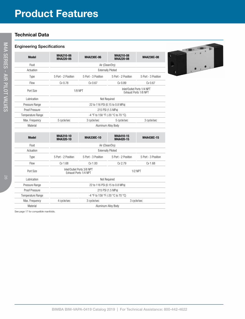
Model M4A210-06 M4A220-06 M4A230C-06 M4A210-08
M4A220-08 M4A230C-08
Fluid Air (Clean/Dry)
Actuation Externally Piloted
Type 5 Port - 2 Position 5 Port - 3 Position 5 Port - 2 Position 5 Port - 3 Position
Flow Cv 0.78 Cv 0.67 Cv 0.89 Cv 0.67
Port Size 1/8 NPT Inlet/Outlet Ports 1/4 NPTExhaust Ports 1/8 NPT
Lubrication Not Required
Pressure Range 22 to 116 PSI (0.15 to 0.8 MPa)
Proof Pressure 215 PSI (1.5 MPa)
Temperature Range -4 °F to 158 °F (-20 °C to 70 °C)
Max. Frequency 5 cycle/sec 3 cycle/sec 5 cycle/sec 3 cycle/sec
Material Aluminum Alloy Body
See page 17 for compatible manifolds.
Product Features
Technical Data
Engineering Specifications
Model M4A310-10 M4A320-10 M4A330C-10 M4A410-15
M4A420-15 M4A430C-15
Fluid Air (Clean/Dry)
Actuation Externally Piloted
Type 5 Port - 2 Position 5 Port - 3 Position 5 Port - 2 Position 5 Port - 3 Position
Flow Cv 1.68 Cv 1.00 Cv 2.79 Cv 1.68
Port Size Inlet/Outlet Ports 3/8 NPTExhaust Ports 1/4 NPT 1/2 NPT
Lubrication Not Required
Pressure Range 22 to 116 PSI (0.15 to 0.8 MPa)
Proof Pressure 215 PSI (1.5 MPa)
Temperature Range -4 °F to 158 °F (-20 °C to 70 °C)
Max. Frequency 4 cycle/sec 3 cycle/sec 3 cycle/sec
Material Aluminum Alloy Body
M4A SERIES - AIR PILO
T VALVES

BIMBA BIM-VAPA-0419 Catalog 2019 | For Technical Assistance: 800-442-4622
27
How To Specify
Product Information
Dimensions (mm) – Single Air PilotModel A B C D E F G H J
M4A210-06 1/8 NPT 36 13.7 17 22 31.7 77.7 20 21.7
M4A210-08 1/8 NPT 36 13.7 17 22 31.7 77.7 20 21.7
M4A310-10 1/4 NPT 45 17.5 20 27 40 95.5 24 28
M4A410-15 1/2 NPT 63 25.5 27 34 57 128 28 43
G
J
H
K
(2) M
L
1/8 NPT
(3) N
P
R T
U
(2) V
S
(2) A
B
C F
D
E
Model A B C D E F G H JM4A210-06 1/8 NPT 36 13.7 17 22 31.7 77.7 20 21.7M4A210-08 1/8 NPT 36 13.7 17 22 31.7 77.7 20 21.7M4A310-08 1/4 NPT 45 17.5 20 27 40 95.5 24 28M4A310-10 1/4 NPT 45 17.5 20 27 40 95.5 24 28M4A410-15 1/2 NPT 63 25.5 27 34 57 128 28 43
Model K L M N P R S T U VM4A210-06 35 7 4.3 1/8 NPT 38 12.7 0 22.7 18 3.3M4A210-08 35 7 4.3 1/4 NPT 38 12.7 3 21.2 21 3.3M4A310-08 40 6.5 4.3 1/4 NPT 50 28 0 29 22 4.3M4A310-10 40 6.5 4.3 3/8 NPT 50 28 4 28 24 4.3M4A410-15 50 7.5 5.5 1/2 NPT 72 43 4 39 36 4.3
H J
K
L
M
(2) N
(2) 1/8 NPT
(3) A
P
R
S
T
U
(2) V (2) B
C
D
E
F
G
Model A B C D E F G H J
M4A220-06 1/8 NPT1/8 NPT 36 28 17 22 46 92 20
M4A220-08 1/4 NPT
M4A320-08 1/4 NPT1/4 NPT 45 33 20 27 55.5 111 24
M4A320-10 3/8 NPT
M4A420-15 1/2 NPT 1/2 NPT 63 39.5 27 34 71 142 28
Model K L M N P R S T U V
M4A220-0636 35 7 4.3 38 27
0 27 183.3
M4A220-08 3 35.5 21
M4A320-0843.5 40 6.5 4.3 50 30.5
0 44.5 224.3
M4A320-10 4 43.5 24
M4A420-15 57 50 7.5 5.5 72 35 4 53 36 4.3
(2) N J H
K
M L
(2) 1/8 NPT
(3) A
U
T
P
R
(2) V
S
(2) B
D
E F
G
C
Model A B C D E F G H J
M4A230C-06 1/8 NPT1/8 NPT 36 28 17 22 46 111 20
M4A230C-08 1/4 NPT
M4A330C-08 1/4 NPT1/4 NPT 45 33 20 27 55.5 130 24
M4A330C-10 3/8 NPT
M4A430C-15 1/2 NPT 1/2 NPT 63 39.5 27 34 71 163 28
Model K L M N P R S T U V
M4A230C-0636 35 7 4.3 38 27
0 27 183.3
M4A230C-08 3 35.5 21
M4A330C-0843.5 40 6.5 4.3 50 30.5
0 44.5 224.3
M4A330C-10 4 43.5 24
M4A430C-15 57 50 7.5 5.5 72 35 4 53 36 4.3
Model K L M N P R S T U VM4A210-06 35 7 4.3 1/8 NPT 38 12.7 0 22.7 18 3.3
M4A210-08 35 7 4.3 1/4 NPT 38 12.7 3 21.2 21 3.3
M4A310-10 40 6.5 4.3 3/8 NPT 50 15 4 28 24 4.3
M4A410-15 50 7.5 5.5 1/2 NPT 72 21 4 39 36 4.3
Dimensions (mm) – Double Air PilotModel A B C D E F G H J
M4A220-06 1/8 NPT 1/8 NPT 36 28 17 22 46 92 20
M4A220-08 1/4 NPT 1/8 NPT 36 28 17 22 46 92 20
M4A320-10 3/8 NPT 1/4 NPT 45 33 20 27 55.5 111 24
M4A420-15 1/2 NPT 1/2 NPT 63 39.5 27 34 71 142 28
Model K L M N P R S T U VM4A220-06 36 35 7 4.3 38 27 0 37 18 3.3
M4A220-08 36 35 7 4.3 38 27 3 35.5 21 3.3
M4A320-10 43.5 40 6.5 4.3 50 30.5 4 43.5 24 4.3
M4A420-15 57 50 7.5 5.5 72 35 4 53 36 4.3
Dimensions (mm) – Double Air Pilot - Closed Center
Model A B C D E F G H JM4A230C-06 1/8 NPT 1/8 NPT 36 28 17 22 46 111 20
M4A230C-08 1/4 NPT 1/8 NPT 36 28 17 22 46 111 20
M4A330C-10 3/8 NPT 1/4 NPT 33 33 20 27 55.5 130 24
M4A430C-15 1/2 NPT 1/2 NPT 39.5 39.5 27 34 71 163 28
Model K L M N P R S T U VM4A230C-06 36 35 7 4.3 38 27 0 37 18 3.3
M4A230C-08 36 35 7 4.3 38 27 3 35.5 21 3.3
M4A330C-10 43.5 40 6.5 4.3 50 30.5 4 43.5 24 4.3
M4A430C-15 57 50 7.5 5.5 72 35 4 53 36 4.3
M4A SERIES - AIR PILO
T VALVES

BIMBA BIM-VAPA-0419 Catalog 2019 | For Technical Assistance: 800-442-4622
28
How To Order
How To Order
B
PR
A
S20
B
PR
A
S10
B
PR
A
S30C
M4A 2 10-08
Model
2 = 200 Series
3 = 300 Series
4 = 400 Series
Product Line
M4A SeriesType
10 = Single Solenoid
20 = Double Solenoid
30C = 3 Position Double Air Pilot Closed Center
Port Size
06 = 1/8 NPT (200 Series)
08 = 1/4 NPT (200 Series)
10 = 3/8 NPT (300 Series)
15 = 1/2 NPT (400 Series)
M4A SERIES - AIR PILO
T VALVES

BIMBA BIM-VAPA-0419 Catalog 2019 | For Technical Assistance: 800-442-4622
29
Model 210-06 230-06 310-08 330-08
Fluid Air (Clean/Dry)
Actuation Hand Lever
Type 5 Port - 2 Position 5 Port - 3 Position 5 Port - 2 Position 5 Port - 3 Position
Flow Cv 0.78 Cv 0.67 Cv 1.39 Cv 1.00
Port Size 1/8 NPT 1/4 NPT
Lubrication Not Required
Pressure Range 0 to 116 PSI (0 to 0.8 MPa)
Proof Pressure 215 PSI (1.5 MPa)
Temperature Range -4 °F to 158 °F (-20 °C to 70 °C)
Material Aluminum Alloy Body
N
P
M
L
R
(3) S
V
U
(5)A
T
B
C
D
E
F
H G
J
K
Model A B C D E F G H J K L M N P R S T U V
M4H210-06 1/8 NPT 81.5 32.5 22 90 13.7 69.5 36 15 M16X1.5 20 21.7 35 23.5 31.7 4.3 18 18 22.7
M4H310-08 1/4 NPT 101 40.5 27 93.5 17.5 87 45 18 M20X1.5 24 28 40 27.5 40 4.3 18 22 29
Model A B C D E F G H J K L M N P R S T U VM4H210-06/M4HA210-06 1/8 NPT 81.5 32.5 22 90 14.5 69.5 36 15 M16X1.5 20 22.5 35 23.5 32.5 4.3 18 18 23.5
M4H310-08/M4HA310-08 1/4 NPT 101 40.5 27 93.5 18 87 45 18 M20X1.5 24 28.5 40 27.5 40.5 4.3 18 22 29.5
M4H230C-06/M4H230E-06 1/8 NPT 81.5 32.5 22 90.5 14.5 69.5 36 17 M16X1.5 20 22.5 35 23.5 32.5 4.3 18 18 23.5
M4H330C-08/M4H330E-08 1/4 NPT 101 40.5 27 94 18 87 45 20 M20X1.5 24 28.5 40 27.5 40.5 4.3 18 22 29.5
M4HA230C-06/M4HA230E-06 1/8 NPT 100.5 32.5 22 90.5 14.5 88.5 36 17 M16X1.5 20 22.5 35 23.5 32.5 4.3 18 18 23.5
M4HA330C-08/M4HA330E-08 1/4 NPT 120 40.5 27 94 18 106 45 20 M20X1.5 24 28.5 40 27.5 40.5 4.3 18 22 29.5
Product Features
Technical Data
Engineering Specifications
Dimensions (mm)
Panel Mount
Installation Options
Body Mount
> Unscrew and remove handle, nut, and boot
> Reassemble in panel > Panel thickness (200 Series: ≤5mm, 300 Series: ≤ 6mm)
> Panel mounting hole diameter (200 Series: Ø16.75mm, 300 Series: Ø21mm)
> See Dimensions for mounting hole size and spacing
> Screws not included
M4H
SERIES - HAN
D LEVER VALVES

BIMBA BIM-VAPA-0419 Catalog 2019 | For Technical Assistance: 800-442-4622
30
A B
R P S
A B
R PS
A B
R P S
B
PR
A
S
A B
R P S
A B
R P S
How To Order
How To Order
M4H 2 10-06
Model
2 = 200 Series
3 = 300 Series
Product Line
M4H Series = Manual Return
M4HA Series = Spring Return
Type
10 = 5 Port - 2 Position
30C = 5 Port - 3 Position Closed Center
30E = 5 Port - 3 Position Exhaust Center
Port Size
06 = 1/8 NPT (200 Series)
08 = 1/4 NPT (300 Series)
10 (Spring Return)10 (Manual Return)
30C (Manual Return)30C (Manual Return) 30E (Manual Return) 30E (Spring Return)
M4H
SERIES - HAN
D LEVER VALVES

BIMBA BIM-VAPA-0419 Catalog 2019 | For Technical Assistance: 800-442-4622
31
(4) A
C
B
E
F
G
8 10
45°
45°
K J
H
(4) 6.5
(2) 3 L
M
N
P
B
R
A
Model A B C D E F
M4HV3 1/4 NPT 88.5 56 1.5 M40X1.5 13.5
M4HV4 1/2 NPT 110 72 2 M52X1.5 18
Model G H J K L M N
M4HV3 104 74 62 51 62 74 140
M4HV4 128 102 89 64 81 94 160
Model A B C E F G H J K L M NM4HV3 1/4 NPT 88.5 56 M40X1.5 13.5 104 74 62 51 62 74 140
M4HV4 1/2 NPT 110 72 M52X1.5 18 128 102 89 64 81 94 160
Product Features
Technical Data
Engineering Specifications
Model M4HV310-08-S M4HV330-08-S M4HV410-15-S M4HV430-15-S
Fluid Air (Clean/Dry)
Actuation Rotary Hand Lever
Type 4 Port - 2 Position - Detented
4 Port - 3 Position - Closed Center
- Detented
4 Port -2 Position - Detented
4 Port - 3 Position - Closed Center
- Detented
Flow Cv 1.67 Cv 4.89
Port Size 1/4 NPT 1/2 NPT
Lubrication Not Required
Pressure Range 0 to 145 PSI (0 to 1.0 MPa)
Proof Pressure 215 PSI (1.5 MPa)
Temperature Range -4 °F to 158 °F (-20 °C to 70 °C)
Material Aluminum Alloy Body
Dimensions (mm)
(4) A
C
B
E
F
G
8 10
45°
45°
K J
H
(4) 6.5
(2) 3 L
M
N
P
B
R
A
Model A B C D E F
M4HV3 1/4 NPT 88.5 56 1.5 M40X1.5 13.5
M4HV4 1/2 NPT 110 72 2 M52X1.5 18
Model G H J K L M N
M4HV3 104 74 62 51 62 74 140
M4HV4 128 102 89 64 81 94 160
M4H
V SERIES - HAN
D LEVER VALVES

BIMBA BIM-VAPA-0419 Catalog 2019 | For Technical Assistance: 800-442-4622
32
How To Order
How To Order
B
P R
A
10
B
P R
A
30
M4HV 3 10-08-S
Model
3 = 300 Series
4 = 400 Series
Product Line
M4HV Series
Type
10 = 4 Port - 2 Position
30 = 4 Port - 3 Position - Closed Center
Port Size
08 = 1/4 NPT (300 Series)
15 = 1/2 NPT (400 Series)
Mounting
S = Panel Nut
M4H
V SERIES - HAN
D LEVER VALVES

BIMBA BIM-VAPA-0419 Catalog 2019 | For Technical Assistance: 800-442-4622
33
Model M4L210-06 M4L310-08
Fluid Air (Clean/Dry)
Actuation Push-Pull Knob
Type 5 Port - 2 Position - Detented
Flow Cv 0.78 Cv 1.39
Port Size 1/8 NPT 1/4 NPT
Lubrication Not Required
Pressure Range 0 to 116 PSI (0 to 0.8 MPa)
Proof Pressure 215 PSI (1.5 MPa)
Temperature Range -4 °F to 158 °F (-20 °C to 70 °C)
Material Aluminum Alloy Body
G
10
H (3) 4.3
J
K
L M
6 MAX
N
P
R
S
(2) 3.3
T
U
(5) A
D E
F
B
C
Model A B C D E F G H J K L M N P R S T U
M4L210-06 1/8 NPT 36 13.7 17 22 31.7 98 65 20 21.7 23.5 35 M14X1.0 22 38 12.7 18 22.7
M4L310-08 1/4 NPT 45 17.5 20 27 40 115 80.8 24 28 27.5 40 M16X1.0 25 50 15 22 29Model A B C D E F G H J K L M N P R S T U
M4L210-06 1/8 NPT 36 14.5 17 22 32.5 106 65.8 20 22.5 23.5 35 M14X1.0 25 38 13.5 18 23.5
M4L310-08 1/4 NPT 45 18 20 27 40.5 121.5 81 24 28.5 27.5 40 M16X1.0 25 50 15.5 22 29.5
Product Features
Technical Data
Engineering Specifications
Dimensions (mm)
G
10
H (3) 4.3
J
K
L M
6 MAX
N
P
R
S
(2) 3.3
T
U
(5) A
D E
F
B
C
Model A B C D E F G H J K L M N P R S T U
M4L210-06 1/8 NPT 36 13.7 17 22 31.7 98 65 20 21.7 23.5 35 M14X1.0 22 38 12.7 18 22.7
M4L310-08 1/4 NPT 45 17.5 20 27 40 115 80.8 24 28 27.5 40 M16X1.0 25 50 15 22 29
G
10
H (3) 4.3
J
K
L M
6 MAX
N
P
R
S
(2) 3.3
T
U
(5) A
D E
F
B
C
Model A B C D E F G H J K L M N P R S T U
M4L210-06 1/8 NPT 36 13.7 17 22 31.7 98 65 20 21.7 23.5 35 M14X1.0 22 38 12.7 18 22.7
M4L310-08 1/4 NPT 45 17.5 20 27 40 115 80.8 24 28 27.5 40 M16X1.0 25 50 15 22 29
M4L SERIES - PUSH
-PULL VALVES

BIMBA BIM-VAPA-0419 Catalog 2019 | For Technical Assistance: 800-442-4622
34
How To Order
How To Order
B
PR
A
S
M4L 2 10-06
Model
2 = 200 Series
3 = 300 Series
Product Line
M4L Series
Type
10 = 5 Port - 2 Position
Port Size
06 = 1/8 NPT (200 Series)
08 = 1/4 NPT (300 Series)
M4L SERIES - PUSH
-PULL VALVES

BIMBA BIM-VAPA-0419 Catalog 2019 | For Technical Assistance: 800-442-4622
35
Model M4F210-08-G M4F210-08-LG
Fluid Air (Clean/Dry)
Actuation Foot Pedal
Type 5 Port - 2 Position
Flow Cv 0.78 Cv 0.78
Lubrication Not Required
Pressure Range 0 to 116 PSI (0 to 0.8 MPa)
Proof Pressure 215 PSI (1.5 MPa)
Temperature Range -4 °F to 158 °F (-20 °C to 70 °C)
Material Aluminum Alloy Body
Technical Data
Engineering Specifications
10.5 137
133
53
87
A
A 6
21 42
25
(3) 1/4 NPT
SECTION A-A
135 73
6 24 75.7
3
170 200
245
85 99
10.5 137
133
53
87
A
A 6
21 42
25
(3) 1/4 NPT
SECTION A-A
135 73
6 24 75.7
3
170 200
245
85 99
10.5 137
133
53
87
A
A 6
21 42
25
(3) 1/4 NPT
SECTION A-A
135 73
6 24 75.7
3
170 200
245
85 99
Dimensions (mm)
Product FeaturesM
4F SERIES - FOO
T PEDAL VALVES

BIMBA BIM-VAPA-0419 Catalog 2019 | For Technical Assistance: 800-442-4622
36
How To Order
How To Order
B
PR
A
S
B
PR
A
S
G LG
M4F 2 10-08-G
Model
2 = 200 Series
Product Line
M4F Series
Type
10 = 5 Port - 2 Position
Port Size
08 = 1/4 NPT
Style
G = Non-Locking with Guard
LG = Locking with Guard
M4F SERIES - FO
OT PED
AL VALVES
BIMBA BIM-VAPA-0419 Catalog 2019 | For Technical Assistance: 800-442-4622
37
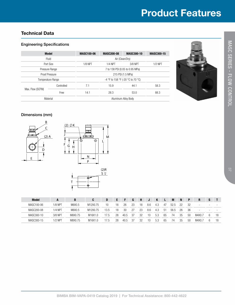
Model MASC100-06 MASC200-08 MASC300-10 MASC300-15
Fluid Air (Clean/Dry)
Port Size 1/8 NPT 1/4 NPT 3/8 NPT 1/2 NPT
Pressure Range 7 to 138 PSI (0.05 to 0.95 MPa)
Proof Pressure 215 PSI (1.5 MPa)
Temperature Range -4 °F to 158 °F (-20 °C to 70 °C)
Max. Flow (SCFM)Controlled 7.1 15.9 44.1 58.3
Free 14.1 28.3 53.0 88.3
Material Aluminum Alloy Body
Model A B C D E F G H J K L M N P R S T
MASC100-06 1/8 NPT M6X0.5 M12X0.75 10 18 26 23 18 8.6 4.3 47 52.5 22 32 - - -
MASC200-08 1/4 NPT M6X0.5 M12X0.75 13.5 18 30 27 23 8.6 4.3 51 56.5 26 36 - - -
MASC300-10 3/8 NPT M8X0.75 M16X1.0 17.5 28 40.5 37 32 10 5.3 65 74 35 50 M4X0.7 6 18
MASC300-15 1/2 NPT M8X0.75 M16X1.0 17.5 28 40.5 37 32 10 5.3 65 74 35 50 M4X0.7 6 18
Product Features
Technical Data
Engineering Specifications
Dimensions (mm)
P N
H G F
J
(2) K
L M
(2)RS
T
(2) A
E
D
B
C
Model A B C D E F G H J K L M N P R S T
MASC100-06 1/8 NPTM6X0.5 M12X0.75
1018
26 23 188.6 4.3
46.8 52.3 22 32-- -- --
MASC200-08 1/4 NPT 13.5 30 27 23 50.8 56.3 26 36
MASC300-10 3/8 NPTM8X0.75 M16X1.0 17.5 28 40.5 37 32 10.2 5.3 65 74 35 50 M4X0.7 6 18
MASC300-15 1/2 NPT
MASC SERIES - FLO
W CO
NTRO
L

BIMBA BIM-VAPA-0419 Catalog 2019 | For Technical Assistance: 800-442-4622
38
How To Order
How To Order
P A
MASC 200 08Product Line
M4F Series
Model
1 = 100 Series
2 = 200 Series
3 = 300 Series
Port Size
06 = 1/8 NPT (100 Series)
08 = 1/4 NPT (200 Series)
10 = 3/8 NPT (300 Series)
15 = 1/2 NPT (300 Series)
MASC SERIES - FLO
W CO
NTRO
L

BIMBA BIM-VAPA-0419 Catalog 2019 | For Technical Assistance: 800-442-4622
39
Air preparation equipment is a crucial element in many pneumatic circuits. Filters, regulators, and lubricators provide improved operation in pneumatic valves and actuators. Accessories such as gauges and switches allow you to further monitor your systems and ensure quality operation.
Air Preparation Equipment

Contents41 MGR Series Regulators
41 – Engineering Specifications 41 – Performance Data 42 – Dimensions 43 – How To Order
44 MSR Series Mini Regulators 44 – Engineering Specifications 44 – Performance Data & Dimensions 45 – How To Order
46 MGF Series General Purpose Filters 46 – Engineering Specifications 46 – Performance Data 47 – Dimensions 48 – How To Order
49 MGFB Series Coalescing Filters 49 – Engineering Specifications 49 – Performance Data 50 – Dimensions 51 – How To Order
52 MGL Lubricators 52 – Engineering Specifications 52 – Performance Data 53 – Dimensions 54 – How To Order
55 MGFR Series Filter Regulators 55 – Engineering Specifications 55 – Performance Data 56 – Dimensions 57 – How To Order
58 MGFC Series Filter Regulator Lubricators 58 – Engineering Specifications 58 – Performance Data 59 – Dimensions 60 – How To Order
61 MGZ Series Pressure Relief Valves 61 – Engineering Specifications 61 – Dimensions 61 – Modular Connecting Kit 62 – How To Order
63 MGV Series Soft Start/Dump Valves 63 – Engineering Specifications 63 – Dimensions 63 – Modular Connecting Kit 64 – How To Order
65 Modular Connecting Kits 65 – Dimensions 66 – How To Order
67 Mounting Brackets 67 – Dimensions 68 – How To Order
69 Air Distribution Blocks 69 – Engineering Specifications 69 – Dimensions 69 – Modular Connecting Kit 70 – How To Order
71 Air Preparation Equipment – Service Parts 71 – Filtering Specifications 71 – Types, Descriptions & Compatibility 72 – How To Order
73 Round Gauges 73 – Engineering Specifications 73 – Dimensions 74 – How To Order
75 Digital Gauges 75 – Engineering Specifications 75 – Dimensions 76 – How To Order 76 – Display Description
77 Digital Pressure Switches 77 – Engineering Specifications 77 – Analog Output Characteristics 78 – Dimensions & Accessories 79 – How To Order

BIMBA BIM-VAPA-0419 Catalog 2019 | For Technical Assistance: 800-442-4622
41
Model MGR
Fluid Air (Clean/Dry)
Type Relieving Regulator with Push to Lock Adjustment Knob
Pressure Range Blank - 7 to 130 PSI (0.05 to 0.9 MPa)L - 7 to 60 PSI (0.05 to 0.4 MPa)
Proof Pressure 215 PSI (1.5 MPa)
Temperature Range -4 °F to 158 °F (-20 °C to 70 °C)
Material Aluminum Alloy Body
Pressure Gauge Square/Flush-Mounted Gauge or Large Round/Port-Mounted Gauge
Mounting Individual Stamped Steel Bracket or Modular Connecting Kit (page 38) or Panel Mount
Includes Stamped Steel Bracket / Panel Nut
Product Features
Technical Data
Engineering Specifications
Performance Data MGR
0102030405060708090
0 20 40 60 80 100 120 140
Out
let P
ress
ure
(psi
)
Flow (SCFM)
MGR200 Flow Characteristics MGR200
0102030405060708090
0 20 40 60 80 100 120 140 160
Out
let P
ress
ure
(psi
)
Flow (SCFM)
MGR300 Flow Characteristics MGR300
0102030405060708090
0 50 100 150 200 250
Out
let P
ress
ure
(psi
)
Flow (SCFM)
MGR400Flow Characteristics MGR400
0102030405060708090
0 50 100 150 200 250 300 350 400 450
Out
let P
ress
ure
(psi
)
Flow (SCFM)
MGR600 Flow Characteristics MGR600
26
29
32
0 20 40 60 80 100 120 140
Out
let P
ress
ure
(psi
)
Inlet Pressure (psi)
MGR300
Set Point
26
29
32
0 20 40 60 80 100 120 140
Out
let P
ress
ure
(psi
)
Inlet Pressure (psi)
MGR200
Set Point
Regulator Characteristics MGR200
26
29
32
0 20 40 60 80 100 120 140 160
Out
let P
ress
ure
(psi
)
Inlet Pressure (psi)
MGR400
Set Point
26
29
32
0 20 40 60 80 100 120 140 160
Out
let P
ress
ure
(psi
)
Inlet Pressure (psi)
MGR600
Set Point
Regulator Characteristics MGR300 Regulator Characteristics MGR400 Regulator Characteristics MGR600
MG
R SERIES - REGULATO
RS

BIMBA BIM-VAPA-0419 Catalog 2019 | For Technical Assistance: 800-442-4622
42
Model A B C D E F G H J K L M NMGR_200-06 30 32 M30 x 1.5 1/8 NPT 55 34 28 15.5 5.5 47 43 89 38
MGR_200-08 30 32 M30 x 1.5 1/4 NPT 55 34 28 15.5 5.5 47 43 89 38
MGR_300-08 41 31 M40 x 1.5 1/4 NPT 53 40 38 8 6.5 60 46 112.5 50.8
MGR_300-10 41 31 M40 x 1.5 3/8 NPT 53 40 38 8 6.5 60 46 112.5 50.8
MGR_400-15 50 40 M55 x 2.0 1/2 NPT 72 55 52 11 8.5 80 53 140.5 67.5
MGR600-20 70 48 M68 x 1.5 3/4 NPT 90 66 64 13 11 99 73.5 191.5 85
MGR600-25 70 48 M68 x 1.5 1 NPT 90 66 64 13 11 99 73.5 191.5 85
Product Information
Dimensions (mm) E
G
M L J
K
N
F
H
A B
(2) D
27.2(MGRK200
ONLY)
30.6(MGRK200
ONLY)
C BRACKETINCLUDED
Model A B C D E F G H J K L M
MGR200-0630 32 M30 x 1.5
1/8 NPT55 34 28 15.5 5.5 47 43 89
MGR200-08 1/4 NPT
MGR300-0841 31 M40 x 1.5
1/4 NPT53 40 38 8 6.5 60 46 112.5
MGR300-10 3/8 NPT
MGR400-15 50 40 M55 x 2.0 1/2 NPT 72 55 52 11 8.5 80 53 140.5
MGR600-2070 48 M68 x 1.5
3/4 NPT90 66 64 13 11 99 43 89
MGR600-25 1 NPT
How To Specify
MG
R SERIES - REGULATO
RS

BIMBA BIM-VAPA-0419 Catalog 2019 | For Technical Assistance: 800-442-4622
43
How To Order
How To Order
MGR MGRK
MGR K 300-08-L-R
Product Line
MGR Series Model
200 Series
300 Series
400 Series
600 Series
³ See page 73 for dimensions
Gauge Type
Blank = Square/Flush
R = Round/Port-Mounted3
Port Size
06 = 1/8 NPT (200 Series)
08 = 1/4 NPT (200, 300 Series)
10 = 3/8 NPT (300 Series)
15 = 1/2 NPT (400 Series)
20 = 3/4 NPT (600 Series)
25 = 1 NPT (600 Series)
Pressure Range
Blank = Square/Flush
L = 7-60 PSI2
² L option only available with 200, 300 & 400 series
Series
Blank = Standard Relieving Regulator
K = Relieving Regulator with Reverse Flow1
¹ K option only available with 200, 300 & 400 series
MG
R SERIES - REGULATO
RS

BIMBA BIM-VAPA-0419 Catalog 2019 | For Technical Assistance: 800-442-4622
44
Model MSR200-06 MSR200-08
Fluid Air (Clean/Dry)
Port Size 1/8 NPT 1/4 NPT
Type Relieving Regulator with Push to Lock Adjustment Knob
Pressure Range 7 to 130 PSI (0.05 to 0.9 MPa)
Proof Pressure 215 PSI (1.5 MPa)
Temperature Range -4 °F to 158 °F (-20 °C to 70 °C)
Material Aluminum Alloy Body
Mounting Inline via Bracket / Panel Mount
Includes Gauge1 / Stamped Steel Bracket / Panel Nut / 2 Gauge Locations
¹ 1/8 NPT, 40mm round gauge, 0-140 PSI
0102030405060708090
0 10 20 30 40
Out
let P
ress
ure
(psi
)
Flow (SCFM)
MSR200 Flow Characteristics
Product Features
Technical Data
Engineering Specifications
Performance Data MSR200
26
29
32
0 20 40 60 80 100 120 140
Out
let P
ress
ure
(psi
)
Inlet Pressure (psi)
MSR200
Set Point
Regulation Characteristics
Dimensions
50
5.5
74.5WHEN
ADJUSTMENTKNOB LOCKED
2
40
34
2 7
42
30 51.5 38
28
10
26
(2) 1/8 NPT 06: 1/808: 1/4
M30 x 1.5BRACKETINCLUDED
GAUGEINCLUDED
BOTH SIDESPRESSURE GAUGE
PORTM
SR SERIES - MIN
I REGULATO
RS

BIMBA BIM-VAPA-0419 Catalog 2019 | For Technical Assistance: 800-442-4622
45
How To Order
How To Order
MSR 200-08Product Line
MSR Series
Model
200
Port Size
06 = 1/8 NPT
08 = 1/4 NPT
MSR SERIES - M
INI REG
ULATORS
BIMBA BIM-VAPA-0419 Catalog 2019 | For Technical Assistance: 800-442-4622
46
Technical Data
Engineering Specifications
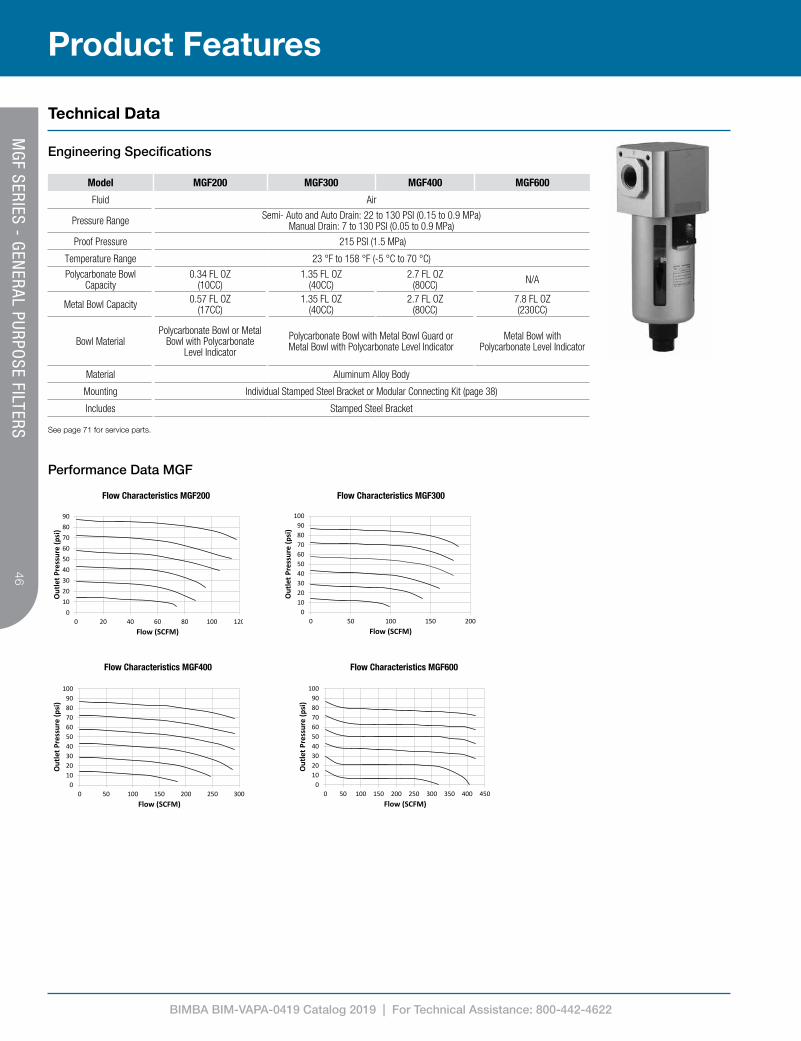
Model MGF200 MGF300 MGF400 MGF600
Fluid Air
Pressure Range Semi- Auto and Auto Drain: 22 to 130 PSI (0.15 to 0.9 MPa)Manual Drain: 7 to 130 PSI (0.05 to 0.9 MPa)
Proof Pressure 215 PSI (1.5 MPa)
Temperature Range 23 °F to 158 °F (-5 °C to 70 °C)Polycarbonate Bowl
Capacity0.34 FL OZ
(10CC)1.35 FL OZ
(40CC)2.7 FL OZ
(80CC) N/A
Metal Bowl Capacity 0.57 FL OZ(17CC)
1.35 FL OZ(40CC)
2.7 FL OZ(80CC)
7.8 FL OZ(230CC)
Bowl MaterialPolycarbonate Bowl or Metal
Bowl with Polycarbonate Level Indicator
Polycarbonate Bowl with Metal Bowl Guard orMetal Bowl with Polycarbonate Level Indicator
Metal Bowl with Polycarbonate Level Indicator
Material Aluminum Alloy Body
Mounting Individual Stamped Steel Bracket or Modular Connecting Kit (page 38)
Includes Stamped Steel Bracket
See page 71 for service parts.
Performance Data MGF
0102030405060708090
0 20 40 60 80 100 120
Out
let P
ress
ure
(psi
)
Flow (SCFM)
MGF200 Flow Characteristics MGF200
0102030405060708090
100
0 50 100 150 200
Out
let P
ress
ure
(psi
)
Flow (SCFM)
MGF300 Flow Characteristics MGF300
0102030405060708090
100
0 50 100 150 200 250 300
Out
let P
ress
ure
(psi
)
Flow (SCFM)
MGF400 Flow Characteristics MGF400
0102030405060708090
100
0 50 100 150 200 250 300 350 400 450
Out
let P
ress
ure
(psi
)
Flow (SCFM)
MGF600 Flow Characteristics MGF600
Product Features
MG
F SERIES - GEN
ERAL PURPOSE FILTERS

BIMBA BIM-VAPA-0419 Catalog 2019 | For Technical Assistance: 800-442-4622
47
Model A B C D E F
MGF200-06 30 123*137** 1/8 NPT - 27 8.4
MGF200-08 30 123*137** 1/4 NPT - 27 8.4
MGF300-08 41 182 1/4 NPT G 1/8 40 8
MGF300-10 41 182 3/8 NPT G 1/8 40 8
MGF400-15 50 208 1/2 NPT G 1/4 55 11
MGF600-20 70 280 3/4 NPT G 1/4 66 13
MGF600-25 70 280 1 NPT G 1/4 66 13
Model G H J K L M
MGF200-06 5.4 23 93*107**
110*124** 38 47
MGF200-08 5.4 23 93*107**
110*124** 38 47
MGF300-08 6.5 27 143 164 50.8 60
MGF300-10 6.5 27 143 164 50.8 60
MGF400-15 8.6 33.5 166.5 191.5 67.5 80
MGF600-20 11 50 219 256 84.5 99
MGF600-25 11 50 219 256 84.5 99
* Polycarbonate Bowl** Metal Bowl
Product Information
Dimensions (mm)
G H
J
K
L M
E F A
B
(2) C
D
BRACKETINCLUDED
Model A B C D E F G H J K
MGF200-0630 123
1/8 NPT-- 27 2.4 5.4 23 93 110
MGF200-08 1/4 NPT
MGF300-0841 182
1/4 NPTG 1/8 40 8 6.5 27 143 164
MGF300-10 3/8 NPT
MGF400-15 50 208 1/2 NPT G 1/4 55 11 8.6 33.5 166.5 191.5
MGF600-2070 280
3/4 NPTG 1/4 66 13 11 50 219 256
MGF600-25 1 NPT
How To SpecifyM
GF SERIES - G
ENERAL PURPO
SE FILTERS

BIMBA BIM-VAPA-0419 Catalog 2019 | For Technical Assistance: 800-442-4622
48
MGF 300-08-S-W-D
Product Line
MGF Series Model
200 Series
300 Series
400 Series
600 Series² 200 series has polycarbonate bowl with no guard³ 600 series is only available with -D metal bowl
Bowl Type
Blank = Polycarbonate Bowl with Metal Bowl Guard2
D = Metal Bowl3
Port Size
06 = 1/8 NPT (200 Series)
08 = 1/4 NPT (200, 300 Series)
10 = 3/8 NPT (300 Series)
15 = 1/2 NPT (400 Series)
20 = 3/4 NPT (600 Series)
25 = 1 NPT (600 Series)
Drain
Blank = Auto Drain1
M = Manual Drain
S = Semi-Auto Drain
¹ Not available on 200 series
Filtering
Blank = 40µm
W = 5µm
How To Order
How To Order
MG
F SERIES - GEN
ERAL PURPOSE FILTERS

BIMBA BIM-VAPA-0419 Catalog 2019 | For Technical Assistance: 800-442-4622
49
Technical Data
Engineering Specifications
Model MGFB200 MGFB300 MGFB400
Fluid Air to be filtered to 5µ or better
Pressure Range Semi- Auto and Auto Drain: 25 to 130 PSI (0.17 to 0.9 MPa)Manual Drain: 7 to 130 PSI (0.05 to 0.9 MPa)
Proof Pressure 215 PSI (1.5 MPa)
Temperature Range 23 to 158 °F (-5 to 70 °C)
Filtration Rating 0.01µ (95% efficiency)
Max Flow Rate1 5 SCFM 10 SCFM 20 SCFM
Polycarbonate Bowl Capacity 0.34 FL OZ(10CC)
1.35 FL OZ(40CC)
2.7 FL OZ(80CC)
Metal Bowl Capacity 0.57 FL OZ(17CC)
1.35 FL OZ(40CC)
2.7 FL OZ(80CC)
Bowl MaterialPolycarbonate Bowl or
Metal Bowl with Polycarbonate Level Indicator
Polycarbonate Bowl with Metal Bowl Guard orMetal Bowl with Polycarbonate Level Indicator
Material Aluminum Alloy Body
Mounting Individual Stamped Steel Bracket or Modular Connecting Kit (page 38)
Includes Stamped Steel Bracket
¹ Maximum rated flow at 85 PSI inlet pressure for coalescing function.
Performance Data MGFB
0
0.5
1
1.5
2
2.5
3
0 2 4 6 8 10 12
PRES
SURE
DRO
P (P
SI)
FLOW (SCFM)
MGFB200
0
0.5
1
1.5
2
2.5
3
0 2 4 6 8 10 12 14
PRES
SURE
DRO
P (P
SI)
FLOW (SCFM)
MGFB300
0
0.5
1
1.5
2
2.5
3
0 5 10 15 20 25
PRES
SURE
DRO
P (P
SI)
FLOW (SCFM)
MGFB400 Flow Characteristics MGFB200 Flow Characteristics MGFB300 Flow Characteristics MGFB400
See page 71 for service parts.
Product FeaturesM
GFB SERIES - CO
ALESCING
FILTERS

BIMBA BIM-VAPA-0419 Catalog 2019 | For Technical Assistance: 800-442-4622
50
Model G H J K L M
MGFB200-06 5.4 23 93*107**
110*124** 38 47
MGFB200-08 5.4 23 93*107**
110*124** 38 47
MGFB300-08 6.5 27 143 164 50.8 60
MGFB300-10 6.5 27 143 164 50.8 60
MGFB400-15 8.6 33.5 166.5 191.5 67.5 80
* Polycarbonate Bowl** Metal Bowl
Product Information
Dimensions (mm)
G H
J
K
L M
E F A
B
(2) C
D
BRACKETINCLUDED
Model A B C D E F G H J K
MGF200-0630 123
1/8 NPT-- 27 2.4 5.4 23 93 110
MGF200-08 1/4 NPT
MGF300-0841 182
1/4 NPTG 1/8 40 8 6.5 27 143 164
MGF300-10 3/8 NPT
MGF400-15 50 208 1/2 NPT G 1/4 55 11 8.6 33.5 166.5 191.5
MGF600-2070 280
3/4 NPTG 1/4 66 13 11 50 219 256
MGF600-25 1 NPT
How To Specify
MG
FB SERIES - COALESCIN
G FILTERS
Model A B C D E F
MGFB200-06 30 123*137** 1/8 NPT - 27 8.4
MGFB200-08 30 123*137** 1/4 NPT - 27 8.4
MGFB300-08 41 182 1/4 NPT G 1/8 40 8
MGFB300-10 41 182 3/8 NPT G 1/8 40 8
MGFB400-15 50 208 1/2 NPT G 1/4 55 11

BIMBA BIM-VAPA-0419 Catalog 2019 | For Technical Assistance: 800-442-4622
51
How To Order
How To Order
MGFB 300-08-S-1-D
Product Line
MGFB Series Model
200 Series
300 Series
400 Series ² 200 series has polycarbonate bowl with no guard
Bowl Type
Blank = Polycarbonate Bowl with Metal Bowl Guard2
D = Metal Bowl3
Port Size
06 = 1/8 NPT (200 Series)
08 = 1/4 NPT (200, 300 Series)
10 = 3/8 NPT (300 Series)
15 = 1/2 NPT (400 Series)
Drain
Blank = Auto Drain1
M = Manual Drain
S = Semi-Auto Drain
¹ Not available on 200 series
Filtering
1 = 0.01µ Coalescing
MG
FB SERIES - COALESCIN
G FILTERS

BIMBA BIM-VAPA-0419 Catalog 2019 | For Technical Assistance: 800-442-4622
52
Technical Data
Engineering Specifications
See page 71 for service parts.
Model MGL200 MGL300 MGL400 MGL600
Fluid Air (Clean/Dry)
Type Fine Oil Mist
Pressure Range 7 to 130 PSI (0.05 to 0.9 MPa)
Proof Pressure 215 PSI (1.5 MPa)
Temperature Range 23 °F to 158 °F (-5 °C to 70 °C)
Polycarbonate Bowl Capacity 0.85 FL OZ(25CC)
2.5 FL OZ(75CC)
5.4 FL OZ(160CC) N/A
Metal Bowl Capacity 1.08 FL OZ(32CC)
2.5 FL OZ(75CC)
5.4 FL OZ(160CC)
12.8 FL OZ(380CC)
Bowl MaterialPolycarbonate Bowl or Metal
Bowl with Polycarbonate Level Indicator
Polycarbonate Bowl with Metal Bowl Guard or Metal Bowl with Polycarbonate Level Indicator
Metal Bowl with Polycarbonate Level
Indicator
Material Aluminum Alloy Body
Recommended Lubricant Non-Detergent SAE10, ISO VG32, or equivalent
Mounting Individual Stamped Steel Bracket or Modular Connecting Kit (page 38)
Includes Stamped Steel Bracket
Performance Data MGL
Flow Characteristics MGL200 Flow Characteristics MGL300
Flow Characteristics MGL400 Flow Characteristics MGL600
0102030405060708090
100
0 20 40 60 80 100 120 140 160 180 200
Out
let P
ress
ure
(psi
g)
Flow (SCFM)
MGL300
0102030405060708090
100
0 20 40 60 80 100 120 140
Out
let P
ress
ure
(psi
)
Flow (SCFM)
MGL200
0102030405060708090
100
0 50 100 150 200 250 300
Out
let P
ress
ure
(psi
g)
Flow (SCFM)
MGL400
0102030405060708090
100
0 50 100 150 200 250 300 350 400 450
Out
let P
ress
ure
(psi
g)
Flow (SCFM)
MGL600
Product Features
MG
L SERIES - LUBRICATORS
BIMBA BIM-VAPA-0419 Catalog 2019 | For Technical Assistance: 800-442-4622
53
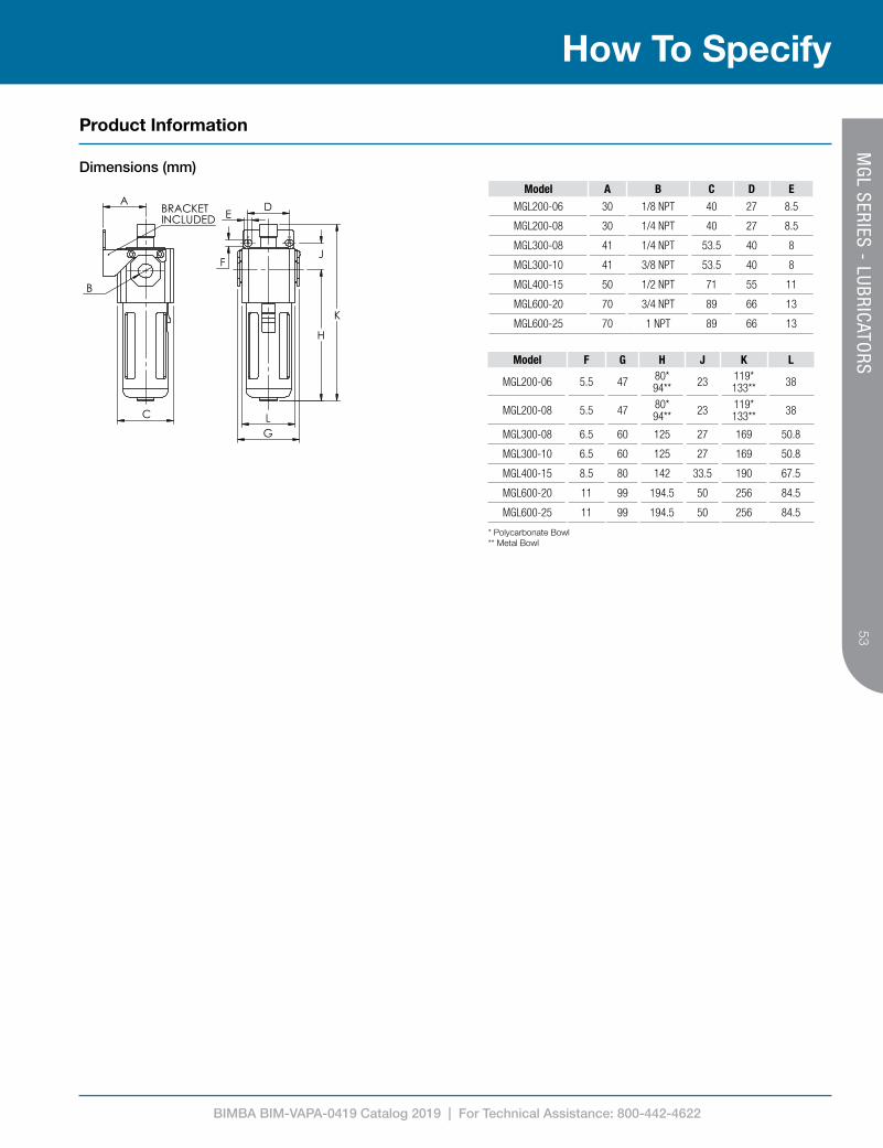
Model A B C D EMGL200-06 30 1/8 NPT 40 27 8.5
MGL200-08 30 1/4 NPT 40 27 8.5
MGL300-08 41 1/4 NPT 53.5 40 8
MGL300-10 41 3/8 NPT 53.5 40 8
MGL400-15 50 1/2 NPT 71 55 11
MGL600-20 70 3/4 NPT 89 66 13
MGL600-25 70 1 NPT 89 66 13
Model F G H J K L
MGL200-06 5.5 47 80*94** 23 119*
133** 38
MGL200-08 5.5 47 80*94** 23 119*
133** 38
MGL300-08 6.5 60 125 27 169 50.8
MGL300-10 6.5 60 125 27 169 50.8
MGL400-15 8.5 80 142 33.5 190 67.5
MGL600-20 11 99 194.5 50 256 84.5
MGL600-25 11 99 194.5 50 256 84.5
A
B
C
BRACKETINCLUDED
F
G
K
L
D E
H
J
Model/Item A B C D E F G H J K
MGL200-06 30 1/8" 40 27 8.5 5.5 47 80 23 119
MGL200-08 30 1/4" 40 27 8.5 5.5 47 80 23 119
MGL300-08 41 1/4" 53.5 40 8 6.5 60 125 27 169
MGL300-10 41 3/8" 53.5 40 8 6.5 60 125 27 169
MGL300-15 41 1/2" 53.5 40 8 6.5 60 125 27 169
MGL400-10 50 3/8" 71 55 11 8.5 80 142 33.5 190
MGL400-15 50 1/2" 71 55 11 8.5 80 142 33.5 190
MGL600-20 70 3/4" 89 66 13 11 99 194.5 50 256
MGL600-25 70 1" 89 66 13 11 99 194.5 50 256
Mead Fluid Dynamics, Inc. 4114 N. Knox Avenue Chicago, IL. 60641 Tele (877)MEAD-USA Fax (773)685-7002
www.mead-usa.com [email protected]
SIZEA
Part NumberDescription
(Drawing for Reference Only)
THE INFORMATION CONTAINED INTHIS DRAWING IS THE SOLE PROPERTY
OF MEAD FLUID DYNAMICS, INC.
* Polycarbonate Bowl** Metal Bowl
Product Information
Dimensions (mm)
How To SpecifyM
GL SERIES - LUBRICATO
RS

BIMBA BIM-VAPA-0419 Catalog 2019 | For Technical Assistance: 800-442-4622
54
MGL 300-08-D
Product Line
MGL Series Model
200 Series
300 Series
400 Series
600 Series² 200 series has polycarbonate bowl with no guard
Bowl Type
Blank = Polycarbonate Bowl with Metal Bowl Guard2
D = Metal Bowl3
Port Size
06 = 1/8 NPT (200 Series)
08 = 1/4 NPT (200, 300 Series)
10 = 3/8 NPT (300 Series)
15 = 1/2 NPT (400 Series)
20 = 3/4 NPT (600 Series)
25 = 1 NPT (600 Series)
How To Order
How To Order
MG
L SERIES - LUBRICATORS

BIMBA BIM-VAPA-0419 Catalog 2019 | For Technical Assistance: 800-442-4622
55
Model MGFR200 MGFR300 MGFR400 MGFR600Fluid AirType Relieving Regulator with Push to Lock Adjustment Knob
Pressure Range
Semi- Auto and Auto Drain: Standard Pressure - 22 to 130 PSI (0.15 to 0.9 MPa) Low Pressure - 22 to 60 PSI (0.15 to 0.4 MPa)Manual Drain: Standard Pressure - 7 to 130 PSI (0.05 to 0.9 MPa)
Low Pressure - 7 to 60 PSI (0.05 to 0.4 MPa)
Proof Pressure 215 PSI (1.5 MPa)Temperature Range 23 °F to 158 °F (-5 °C to 70 °C)
Polycarbonate Bowl Capacity 0.34 FL OZ (10CC) 1.35 FL OZ (40CC) 2.7 FL OZ (80CC) N/AMetal Bowl Capacity 0.57 FL OZ (17CC) 1.35 FL OZ (40CC) 2.7 FL OZ (80CC) 7.8 FL OZ (230CC)
Bowl MaterialPolycarbonate Bowl or Metal
Bowl with Polycarbonate Level Indicator
Polycarbonate Bowl with Metal Bowl Guard or Metal Bowl with Polycarbonate Level Indicator
Metal Bowl with Polycarbonate Level
Indicator
Material Aluminum Alloy BodyMounting Individual Stamped Steel Bracket or Modular Connecting Kit (page 38) or Panel MountIncludes Stamped Steel Bracket / Panel Nut
0102030405060708090
0 20 40 60 80 100 120 140 160
Out
let P
ress
ure
(psi
)
Flow (SCFM)
MGFR300
0102030405060708090
0 20 40 60 80 100 120
Out
let P
ress
ure
(psi
)
Flow (SCFM)
MGFR200
0102030405060708090
0 50 100 150 200 250
Out
let P
ress
ure
(psi
)
Flow (SCFM)
MGFR400
0102030405060708090
0 50 100 150 200 250 300 350 400 450
Out
let P
ress
ure
(psi
)
Flow (SCFM)
MGFR600
See page 71 for service parts.
Technical Data
Engineering Specifications
Product Features
Performance Data MGFR
Flow Characteristics MGFR200 Flow Characteristics MGFR300 Flow Characteristics MGFR400 Flow Characteristics MGFR600
Regulation Characteristics MGFR200 Regulation Characteristics MGFR300 Regulation Characteristics MGFR400 Regulation Characteristics MGFR600
26
29
32
0 20 40 60 80 100 120 140
Out
let P
ress
ure
(psi
)
Inlet Pressure (psi)
MGFR300
Set Point
26
29
32
0 20 40 60 80 100 120 140
Out
let P
ress
ure
(psi
)
Inlet Pressure (psi)
MGFR200
Set Point
26
29
32
0 20 40 60 80 100 120 140
Out
let P
ress
ure
(psi
)
Inlet Pressure (psi)
MGFR400
Set Point
26
29
32
0 20 40 60 80 100 120 140 160
Out
let P
ress
ure
(psi
)
Inlet Pressure (psi)
MGFR600
Set Point
MG
FR SERIES - FILTER REGULATO
RS

BIMBA BIM-VAPA-0419 Catalog 2019 | For Technical Assistance: 800-442-4622
56
Product Information
Dimensions (mm)
How To Specify
Model A B C D E F GMGFR200-06 1/8 NPT 30 32 M30X1.5 - 55 34
MGFR200-08 1/4 NPT 30 32 M30X1.5 - 55 34
MGFR300-08 1/4 NPT 41 31 M40X1.5 G 1/8 53 40
MGFR300-10 3/8 NPT 41 31 M40X1.5 G 1/8 53 40
MGFR400-15 1/2 NPT 50 40 M55X2.0 G 1/4 72 52
MGFR600-20 3/4 NPT 70 48 M68X1.5 G 1/4 90 66
MGFR600-25 1 NPT 70 48 M68X1.5 G 1/4 90 66
Model H J K L M N P R
MGFR200-06 28 15.5 5.5 93*107** 48 161*
175** 47 38
MGFR200-08 28 15.5 5.5 93*107** 48 161*
175** 47 38
MGFR300-08 38 8 6.5 143 46 225.5 60 50.8
MGFR300-10 38 8 6.5 143 46 225.5 60 50.8
MGFR400-15 52 11 8.5 166.5 53 270.5 80 67.5
MGFR600-20 64 13 11 219 76 363 99 84.5
MGFR600-25 64 13 11 219 76 363 99 84.5
L
N
M
F
H G
(2) K
(2) J
P
R
C B
(2) A
D
E
BRACKETINCLUDED
Model A B C D E F
MGFR200-06 1/8 NPT30 32 M30X1.5 -- 55
MGFR200-08 1/4 NPT
MGFR300-08 1/4 NPT41 31 M40X1.5 G 1/8 53
MGFR300-10 3/8 NPT
MGFR400-15 1/2 NPT 50 40 M55X2.0 G 1/4 72
MGFR600-20 3/4 NPT70 47.7 M68X1.5 G 1/4 90
MGFR600-25 1 NPT
Model G H J K L M N P
MGFR200-0634 28 15.5 5.5 93 48 161 47
MGFR200-08
MGFR300-0840 38 8 6.5 143 46 225.5 60
MGFR300-10
MGFR400-15 52 52 11 8.5 166.5 53 270.5 80
MGFR600-2066 64 13 11 219 76 363 99
MGFR600-25
* Polycarbonate Bowl** Metal Bowl
MG
FR SERIES - FILTER REGULATO
RS

BIMBA BIM-VAPA-0419 Catalog 2019 | For Technical Assistance: 800-442-4622
57
How To Order
How To Order
MGFR 300-08-S-L-W-D-R
Product
MGFR Model
200 Series
300 Series
400 Series
600 Series
² 200 series has polycarbonate bowl with no guard³ 600 series is only available with -D metal bowl
Bowl Type
Blank = Polycarbonate Bowl with Metal Bowl Guard2
D = Metal Bowl3
Port Size
06 = 1/8 NPT (200 Series)
08 = 1/4 NPT (200, 300 Series)
10 = 3/8 NPT (300 Series)
15 = 1/2 NPT (400 Series)
20 = 3/4 NPT (600 Series)
25 = 1 NPT (600 Series)
Drain
Blank = Auto Drain1
M = Manual Drain
S = Semi-Auto Drain
¹ Not available on 200 series
Filtering
Blank = 40µm
W = 5µm
Pressure Range
Blank = Standard
L = Low2
² L option only available with 200, 300 and 400 seriesNOTE: See Engineering Specifications for Pressure Range
Gauge Type
Blank = Square/Flush
R = Round
MG
FR SERIES - FILTER REGULATO
RS

BIMBA BIM-VAPA-0419 Catalog 2019 | For Technical Assistance: 800-442-4622
58
Model MGFC200-06-S MGFC200-08-S MGFC300-08 MGFC300-10 MGFC400-15
Fluid Air
Port Size 1/8 NPT 1/4 NPT 1/4 NPT 3/8 NPT 1/2 NPT
Type Relieving Regulator with Push to Lock Adjustment Knob and Fine Oil Mist Lubricator
Pressure Range 22 to 130 PSI (0.15 to 0.9 MPa)
Proof Pressure 215 PSI (1.5 MPa)
Temperature Range 23 °F to 158 °F (-5 °C to 70 °C)
Drain Bowl Capacity 0.34 FL OZ (10CC) 1.35 FL OZ (40CC) 2.7 FL OZ (80CC)
Oil Bowl Capacity 0.85 FL OZ (25CC) 2.5 FL OZ (75CC) 5.4 FL OZ (160CC)
Bowl Material Polycarbonate Bowl Polycarbonate Bowl with Metal Bowl Guard
Material Aluminum Alloy Body
Mounting Modular Connecting Kit (page 38) included
Recommended Lubricant Non-Detergent SAE10, ISO VG32, or equivalent
Drain Semi-Auto Drain Auto Drain
Includes T Style Modular Connecting Kit / Panel Nut
Technical Data
Engineering Specifications
Product Features
See page 71 for service parts.
0102030405060708090
0 20 40 60 80 100 120 140 160
Out
let P
ress
ure
(psi
)
Flow (SCFM)
MGFC300
0102030405060708090
0 20 40 60 80 100 120
Out
let P
ress
ure
(psi
)
Flow (SCFM)
MGFC200
0102030405060708090
0 50 100 150 200 250
Out
let P
ress
ure
(psi
)
Flow (SCFM)
MGFC400
26
29
32
0 20 40 60 80 100 120 140
Out
let P
ress
ure
(psi
)
Inlet Pressure (psi)
MGFC300
Set Point
26
29
32
0 20 40 60 80 100 120 140
Out
let P
ress
ure
(psi
)
Inlet Pressure (psi)
MGFC200
Set Point
26
29
32
0 20 40 60 80 100 120 140
Out
let P
ress
ure
(psi
)
Inlet Pressure (psi)
MGFC400
Set Point
Performance Data MGFC
Flow Characteristics MGFC200 Flow Characteristics MGFC300 Flow Characteristics MGFC400
Regulation Characteristics MGFC200 Regulation Characteristics MGFC300 Regulation Characteristics MGFC400
MG
FC SERIES - FILTER REGULATO
R LUBRICATORS

BIMBA BIM-VAPA-0419 Catalog 2019 | For Technical Assistance: 800-442-4622
59
Product Information
Dimensions (mm)
How To Specify
Model A B C D EMGFC200-06-S 1/8 NPT 62 30 M30X1.5 -
MGFC200-08-S 1/4 NPT 62 30 M30X1.5 -
MGFC300-08 1/4 NPT 72 41.5 M40X1.5 G 1/8
MGFC300-10 3/8 NPT 72 41.5 M40X1.5 G 1/8
MGFC400-15 1/2 NPT 89 50 M55X2.0 G 1/4
Model F G H J K L
MGFC200-06-S 97 93 5.5 8.5 50 161
MGFC200-08-S 97 93 5.5 8.5 50 161
MGFC300-08 124 143 6.5 9 70 225.5
MGFC300-10 124 143 6.5 9 70 225.5
MGFC400-15 164 165.5 8.5 12 80 270.5
H J
F
G L
K
C B
(2) A
T-BRACKETINCLUDED
D
E
Model A B C D E F G H J K L
MGFC200-06-S 1/8 NPT62 30 M30X1.5 -- 97 93 5.5 8.5 50 161
MGFC200-08-S 1/4 NPT
MGFC300-08 1/4 NPT72 41.5 M40X1.5 G 1/8 124 143 6.5 9 70 225.5
MGFC300-10 3/8 NPT
MGFC400-15 1/2 NPT 89 50 M55X2.0 G 1/4 164 165.5 8.5 12 80 269.5
Mead Fluid Dynamics, Inc. 4114 N. Knox Avenue Chicago, IL. 60641 Tele (877)MEAD-USA Fax (773)685-7002
www.mead-usa.com [email protected]
SIZEA
Part NumberDescription
(Drawing for Reference Only)
THE INFORMATION CONTAINED INTHIS DRAWING IS THE SOLE PROPERTY
OF MEAD FLUID DYNAMICS, INC.
MG
FC SERIES - FILTER REGULATO
R LUBRICATORS

BIMBA BIM-VAPA-0419 Catalog 2019 | For Technical Assistance: 800-442-4622
60
MGFC 200-08-S-W
Product Line
MGFC Series Model
200 Series
300 Series
400 Series
Port Size
06 = 1/8 NPT (200 Series)
08 = 1/4 NPT (200, 300 Series)
10 = 3/8 NPT (300 Series)
15 = 1/2 NPT (400 Series)
Drain
Blank = Auto Drain1
S = Semi-Auto Drain2
¹ Not available on 200 series² Not available on 300 & 400 series
Filtering
Blank = 40µm
W = 5µm
How To Order
How To Order
MG
FC SERIES - FILTER REGULATO
R LUBRICATORS

BIMBA BIM-VAPA-0419 Catalog 2019 | For Technical Assistance: 800-442-4622
61
Model MGZ
Fluid Air (Clean/Dry)
Actuation Manual
Valve Type 3 Port - 2 Position
Pressure Range 0 to 130 PSI (0 to 0.9 MPa)
Proof Pressure 215 PSI (1.5 MPa)
Temperature Range -4 °F to 158 °F (-20 °C to 70 °C)
Material Aluminum Alloy Body
Mounting Individual Stamped Steel Bracket orModular Connecting Kit
Knob Motion 90° Twist
Includes Modular Connecting Kit /Stamped Steel Bracket / Lock and Key
H
N
F
G
L
P
J
M
K
C
(2) A
D
E B
BRACKETINCLUDED
R Model A B C D E F
MGZ200-06 1/8 NPT 1/4 NPT42.5 30 40 5.5
MGZ200-08 1/4 NPT 1/4 NPT
MGZ300-08 1/4 NPT 3/8 NPT56.5 41 53.4 6.5
MGZ300-10 3/8 NPT 3/8 NPT
MGZ400-15 1/2 NPT 1/2 NPT 66 50 64 8.5
Model G H J K L M N
MGZ200-068.5 42 27 23 89 36.5 47
MGZ200-08
MGZ300-088 55 40 27 112.5 46 60
MGZ300-10
MGZ400-15 11 65 55 33.5 134 58.5 75
Model A B C D E F GMGZ200-06 1/8 NPT 1/4 NPT 42.5 30 40 5.5 8.5
MGZ200-08 1/4 NPT 1/4 NPT 42.5 30 40 5.5 8.5
MGZ300-08 1/4 NPT 3/8 NPT 56.5 41 53.4 6.5 8
MGZ300-10 3/8 NPT 3/8 NPT 56.5 41 53.4 6.5 8
MGZ400-15 1/2 NPT 1/2 NPT 66 50 64 8.5 11
Model H J K L M N P RMGZ200-06 42 27 23 89 36.5 47 38 7.1
MGZ200-08 42 27 23 89 36.5 47 38 7.1
MGZ300-08 55 40 27 112.5 46 60 51 9.3
MGZ300-10 55 40 27 112.5 46 60 51 9.3
MGZ400-15 65 55 33.5 134 58.5 75 63 10.5
T STYLE
L STYLE
U STYLE
MODULAR CONNECTING KIT INCLUDED
Product Features
Technical Data
Engineering Specifications
Dimensions (mm)
Modular Connecting Kit (included)
T STYLE
L STYLE
U STYLE
MODULAR CONNECTING KIT INCLUDED
T STYLE
L STYLE
U STYLE
MODULAR CONNECTING KIT INCLUDED
MG
Z SERIES - PRESSURE RELIEF VALVES
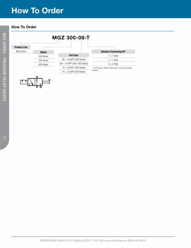
BIMBA BIM-VAPA-0419 Catalog 2019 | For Technical Assistance: 800-442-4622
62
P R
A
MGZ 300-08-T
Product Line
MGZ Series Model
200 Series
300 Series
400 Series
Port Size
06 = 1/8 NPT (200 Series)
08 = 1/4 NPT (200, 300 Series)
10 = 3/8 NPT (300 Series)
15 = 1/2 NPT (400 Series)
Modular Connecting Kit1
T = T Style
L = L Style
U = U Style
¹ All Pressure Relief Valves also include stamped bracket
How To Order
How To Order
MG
Z SERIES - PRESSURE RELIEF VALVES

BIMBA BIM-VAPA-0419 Catalog 2019 | For Technical Assistance: 800-442-4622
63
Product Features
Technical Data
Engineering Specifications
Model MGV200-06 MGV200-08 MGV300-08 MGV300-10 MGV400-15
Fluid Air (Clean/Dry)
Actuation Solenoid Operated, 3/2 Soft Start
Port Size 1/8 NPT 1/4 NPT 1/4 NPT 3/8 NPT 1/2 NPT
Exhaust Port Size 1/4 NPT 3/8 NPT 1/2 NPT
Pressure Range 36 to 130 PSI (0.25 to 0.9 MPa)
Proof Pressure 215 PSI (1.5 MPa)
Temperature Range -4 °F to 158 °F (-20 °C to 70 °C) (Explosion Proof -4 °F to 140 °F [-20 °C to 60 °C])
Electrical Connection DIN / LED Connector or Flying Leads or Explosion Proof Coil Conduit Entry
Voltage Range -15% to +10%
Insulation Class B
Power Consumption1 AC: 3.5VA / DC: 2.5W
Mounting Individual Stamped Steel Bracket or Modular Connecting Kit
Material Aluminum Alloy Body
Connector/Coil1 11mm DIN Connector, Industrial Form B
Includes Modular Connecting Kit / Stamped Steel Bracket
¹ See page 24 for explosion proof specifications
Dimensions (mm)
Modular Connection Kit (included)
F
G
E
C
(2) A
D
BRACKETINCLUDED
M
K
L
N
H
J
B
Model A B C D E
MGV200-06 1/8 NPT 1/4 NPT24.5 30.5 30
MGV200-08 1/4 NPT 1/4 NPT
MGV300-08 1/4 NPT 3/8 NPT31.5 34.5 34
MGV300-10 3/8 NPT 3/8 NPT
MGV400-15 1/2 NPT 1/2 NPT 40.5 39 40.5
Model F G H J K L M
MGV200-06123.5 57 5.5 8 80 67 59
MGV200-08
MGV300-08131 62.5 6.5 8 95 82 74
MGV300-10
MGV400-15 142.5 80 8.5 11 120 102 90
T STYLE
L STYLE
U STYLE
MODULAR CONNECTING KIT INCLUDED
T STYLE
L STYLE
U STYLE
MODULAR CONNECTING KIT INCLUDED
T STYLE
L STYLE
U STYLE
MODULAR CONNECTING KIT INCLUDED
Model A B C D E FMGV200-06 1/8 NPT 1/4 NPT 24.5 30.5 30 123.5
MGV200-08 1/4 NPT 1/4 NPT 24.5 30.5 30 123.5
MGV300-08 1/4 NPT 3/8 NPT 31.5 34.5 34 131
MGV300-10 3/8 NPT 3/8 NPT 31.5 34.5 34 131
MGV400-15 1/2 NPT 1/2 NPT 40.5 39 40.5 142.5
Model G H J K L M NMGV200-06 57 5.5 8 80 67 59 50
MGV200-08 57 5.5 8 80 67 59 50
MGV300-08 62.2 6.5 8 95 82 74 65
MGV300-10 62.2 6.5 8 95 82 74 65
MGV400-15 80 8.5 11 120 102 90 78
MG
V SERIES - SOFT START/D
UMP VALVES

BIMBA BIM-VAPA-0419 Catalog 2019 | For Technical Assistance: 800-442-4622
64
2
1
P
R
A
MGV 300-08-T-24VDC-X
Product Line
MGV Series Model
200 Series
300 Series
400 Series
Port Size
06 = 1/8 NPT (200 Series)
08 = 1/4 NPT (200, 300 Series)
10 = 3/8 NPT (300 Series)
15 = 1/2 NPT (400 Series)
Modular Connecting Kit1
T = T Style
L = L Style
U = U Style¹ All Pressure Relief Valves also include stamped bracket
Voltage
12VDC
24VDC
24VAC 50/60 Hz
120VAC 50/60 Hz ² Not available with 24VAC. Flying Leads are 300mm long.³ See page 24 for specifications. Leads are 580mm long.
Electrical Connection
Blank = DIN Connector
FL = Flying Leads2
X = Explosion Proof3
How To Order
How To Order
MG
V SERIES - SOFT START/D
UMP VALVES

BIMBA BIM-VAPA-0419 Catalog 2019 | For Technical Assistance: 800-442-4622
65
Model A B C D E F G H J KMGA201-P1 66 33 5 30 45 38.3 8.5 5.5 11.5 50
MGA301-P1 88 44 7 41.5 60.4 49.3 9 6.5 13 70
MGA401-P1 104 52 7 50 76 58.5 12 8.6 15.5 80
MGA601-P1 128 64 10 70 104 79.5 16 11 19.8 100
A
C D
E
F
B
(2) G
J
K
(2) H
Model A B C D E F G H J K
MGA201-P1 66 33 5 30 45 38.3 8.5 5.5 11.5 50
MGA301-P1 88 44 7 41.5 60.5 49.3 9 6.5 12.5 70
MGA401-P1 104 52 7 50 76 58.5 12 8.6 16.3 80
MGA601-P1 128 64 10 70 104 79.5 16 11 19.5 100
A
D E
F
C
B
J
G
H
K
Model A B C D E F G H J K
MGA202-P1 51.3 18.3 5 30 45 38.3 8.5 5.5 11.5 8
MGA302-P1 69 22.8 7 41.5 60.5 49.3 9 6.5 12.5 9
MGA402-P1 80 27.5 7 50 76 58.5 12 8.6 16.3 12
MGA602-P1 103.5 39.5 10 70 104 79.5 16 11 19.5 14
A
C
D
E B
F
Model A B C D E F
MGA203-P1 35 18.3 15 30 38.3 11.5
MGA303-P1 43.8 22.8 19.5 38 49.3 12.5
MGA403-P1 52.5 27.5 26 52 58.5 15.5
MGA603-P1 76 39.5 34 68 79.5 19.5
How To Specify
Product Information
Dimensions (mm)
T Style
L Style
Model A B C D E F G H J KMGA202-P1 51 18.3 5 30 45 38.3 8.4 5.4 11.5 8
MGA302-P1 69 22.9 7 41.5 60.4 49.3 9 6.5 13 10.8
MGA402-P1 80 27.5 7 50 76 58.5 12 8.6 15.5 11.8
MGA602-P1 103.4 38.5 10 70 104 79.3 16 11 19.8 13.8
U Style
Model A B C D E FMGA203-P1 35 18.3 15 30 38.3 11.5
MGA303-P1 43.8 22.9 19.5 38 49.3 13
MGA403-P1 52.5 27.5 26 52 58.5 15.5
MGA603-P1 76 38.5 34 68 79.3 19.8
MO
DULAR CO
NN
ECTING
KITS

BIMBA BIM-VAPA-0419 Catalog 2019 | For Technical Assistance: 800-442-4622
66
MGA 3 02-P1
Product Line
MGA Series Model
2 = 200 Series
3 = 300 Series
4 = 400 Series
6 = 600 Series
Type
01 = T Style (connecting and mounting)
02 = L Style (connecting and mounting)
03 = U Style (connecting only)
Material
P1 = Aluminum
How To Order
How To Order
MO
DULAR CO
NN
ECTING
KITS

BIMBA BIM-VAPA-0419 Catalog 2019 | For Technical Assistance: 800-442-4622
67M
OUN
TING
BRACKETS
Product Information
Brackets for MGFR, MGR Series
Brackets for MGF, MGL Series
Brackets for MGV Series
Brackets for MSR Series
Brackets for MGZ Series
D
A B C
H
K
E
J
M L
(2) F
(2) G
A
B
D
C
G
H
K
J
(2) F
(2) E
J
E
L
M
H
(2) F K
(2) G
A B
C
D
A
B
D
C
G
H
K
J
(2) F
(2) E
D
A B C
H
K
E
J
M L
(2) F
(2) G
Model A B C D E F G H J K L MMGB202-P2 20 20 2 45 33 5.4 8.4 27 40 6.4 38.2 42.3
MGB302-P2 27 28 2 60 44 6.5 8 40 55 11.7 51 55
MGB402-P2 30 42 2 75.5 47.3 8.5 11 55 72 9.5 68 72
MGB602-P2 42.4 53.2 2.5 104 51 11 13 66 90 10.7 84.5 90
Model A B C D E F G H J KMGB201-P2 55 49 30 30 15 5.2 24 34.5 2 17.5
MGB301-P2 53 65 41 40.8 8 6.5 22.5 40 2 15
MGB401-P2 72 83 56 55 11 8.5 27 55 2 18
MGB601-P2 90 110.5 70 68 13 11 35 66 2.5 24
Model A B C D E F G H J K L MMGB203-P2 14.8 20 2 39 27.7 5.3 8 67 80 6 50.2 54.2
MGB303-P2 19 25 2 50.2 32.5 6.5 8 82 95 8 65 69
MGB403-P2 21.5 36 2 65.3 40 8.5 11 102 120 8 78 82
Model A B C D E F G H J KMGB204-P2 50 49 30 30 7.2 5.5 20 34 2 14
Model A B C D E F G H J K L MMGB205-P2 20 20 2 45 33 5.4 8.4 27 40 6.4 38.2 42.3
MGB305-P2 27 28 2 60 44 6.5 8 40 55 11.7 51 55
MGB405-P2 30 42 2 75 48 8.5 11 55 72 9.5 64 67
How To SpecifyM
OUN
TING
BRACKETS

BIMBA BIM-VAPA-0419 Catalog 2019 | For Technical Assistance: 800-442-4622
68
MGB 3 02-P2
Product Line
MGB SeriesModel
2 = 200 Series
3 = 300 Series
4 = 400 Series
6 = 600 Series
Type
01 = Bracket for MGFR, MGR Series
02 = Bracket for MGF, MGL Series
03 = Bracket for MGV Series
04 = Bracket for MSR Serie
05 = Bracket for MGZ Series
Material
P2 = Steel
How To Order
How To Order
MO
UNTIN
G BRACKETS

BIMBA BIM-VAPA-0419 Catalog 2019 | For Technical Assistance: 800-442-4622
69
Model MGA Distribution Block
Fluid Air (Clean/Dry)
No. of Auxiliary Ports 2
Pressure Range 0 to 130 PSI (0 to 0.9 MPa)
Proof Pressure 215 PSI (1.5 MPa)
Temperature Range -4 °F to 158 °F (-20 °C to 70 °C)
Material Aluminum Alloy Body
Includes Modular Connecting Kit
Model A B C D EMGA200-06-T 1/8 NPT 36 30 28.5 19
MGA200-08-T 1/4 NPT 36 30 28.5 19
MGA300-08-T 1/4 NPT 44 38 35 26
MGA300-10-T 3/8 NPT 44 38 35 26
MGA400-15-T 1/2 NPT 52 52 42 29.5
MGA600-20-T 3/4 NPT 76 68 60 47
MGA600-25-T 1 NPT 76 68 60 47
Product Features
Technical Data
Engineering Specifications
Dimensions (mm)
B
C
(4) A
D
E
Model/Item A B C D
MGA20006 1/8 36 30 28.5
08 1/4 36 30 28.5
MGA30008 1/4 44 38 35
10 3/8 44 38 35
MGA40010 3/8 52 52 42
15 1/2 52 52 42
MGA60020 3/4 76 68 60
25 1 76 68 60
T STYLE
L STYLE
U STYLE
MODULAR CONNECTING KIT INCLUDED
Modular Connecting Kit (included)
T STYLE
L STYLE
U STYLE
MODULAR CONNECTING KIT INCLUDED
T STYLE
L STYLE
U STYLE
MODULAR CONNECTING KIT INCLUDED
AIR DISTRIBUTIO
N BLO
CKS

BIMBA BIM-VAPA-0419 Catalog 2019 | For Technical Assistance: 800-442-4622
70
MGA 314-08-T
Product Line
MGA Series Model
214 = 200 Series
314 = 300 Series
414 = 400 Series
614 = 600 Series
Port Size
06 = 1/8 NPT (200 Series)
08 = 1/4 NPT (200, 300 Series)
10 = 3/8 NPT (300 Series)
15 = 1/2 NPT (400 Series)
20 = 3/4 NPT (600 Series)
25 = 1 NPT (600 Series)
Modular Connecting Kit1
T = T Style
L = L Style
U = U Style
¹ All Pressure Relief Valves also include stamped bracket
How To Order
How To Order
AIR DISTRIBUTIO
N BLO
CKS

BIMBA BIM-VAPA-0419 Catalog 2019 | For Technical Assistance: 800-442-4622
71
How To Order
How To Order
Filtering
Filtering Material
40µm Bronze
5µm Plastic (200, 300, 400 series) Bronze (600 series)
0.01µm Dual-Layer Borosilicate Glass
AIR PREPARATION
EQUIPM
ENT – SERVICE PARTS
MGF 300-004-1
Filtering
1 = 40µm
2 = 5µm
3 = 0.01µm
Product Line
MGF = Standard Filter Element1
MGFB = Coalescing Filter Element2
¹ Only available with 40µm or 5µm filtering² Only available with 0.01µm filtering
Model
200 Series
300 Series
400 Series
600 Series3
³ MGFB not available with 600 Series

BIMBA BIM-VAPA-0419 Catalog 2019 | For Technical Assistance: 800-442-4622
72
How To Specify
AIR PREPARATION
EQUIPM
ENT – SERVICE PARTS
Type Drain Style Description Part Number Compatibility
Filter and Filter/Regulator Bowls
Manual Drain
200 Series Polycarbonate Bowl MGF200-M 200 Series MGF, MGFB, MGFR
300 Series Polycarbonate Bowl MGF300-M 300 Series MGF, MGFB, MGFR
400 Series Polycarbonate Bowl MGF400-M 400 Series MGF, MGFB, MGFR
600 Series Metal Bowl MGF600-M 600 Series MGF, MGFR
Semi-Auto Drain
200 Series Polycarbonate Bowl MGF200-SA 200 Series MGF, MGFB, MGFR
300 Series Polycarbonate Bowl MGF300-SA 300 Series MGF, MGFB, MGFR
400 Series Polycarbonate Bowl MGF400-SA 400 Series MGF, MGFB, MGFR
600 Series Metal Bowl MGF600-SA 600 Series MGF, MGFR
Auto Drain
300 Series Polycarbonate Bowl MGF300-A 300 Series MGF, MGFB, MGFR
400 Series Polycarbonate Bowl MGF400-A 400 Series MGF, MGFB, MGFR
600 Series Metal Bowl MGF600-A 600 Series MGF, MGFR
Lubricator Bowls
200 Series Polycarbonate Bowl MGL200-BWL 200 Series MGL
300 Series Polycarbonate Bowl MGL300-BWL 300 Series MGL
400 Series Polycarbonate Bowl MGL400-BWL 400 Series MGL
600 Series Metal Bowl MGL600-BWL 600 Series MGL
Replacement Filter, Filter/Regulator, and Lubricator Bowls
Product Information

BIMBA BIM-VAPA-0419 Catalog 2019 | For Technical Assistance: 800-442-4622
73
Model Round Gauges
Fluid Air (Clean/Dry)
Units PSI and kgf/cm2
Pressure Range Blank: 0 to 140 PSI (0 to 1.0 MPa)Low Pressure: 0 to 60 PSI (0 to 0.4 MPa)
Temperature Range -4 °F to 140 °F (-20 °C to 60 °C)
Material Shell: SPCC Steel Core: Brass
Model A BMGFR200/MGR200 62 42
MGFR300/MGR300 61.7 42
MGFR400/MGR400 77.3 52
MGFR600/MGR600 85 52
A
B B
FLATS
C
D
A
E
Model A B C D ERGK/RG-40 42 11 24.5 38.5 1/8 NPT
RGK/RG-50 52 14 26.5 44.5 1/4 NPT
Product Features
Technical Data
Engineering Specifications
Dimension (mm)
ROUN
D G
AUGES
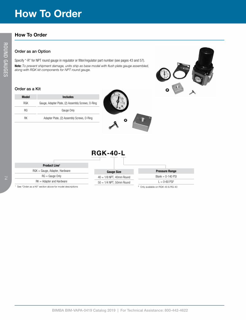
BIMBA BIM-VAPA-0419 Catalog 2019 | For Technical Assistance: 800-442-4622
74
Model Includes
RGK Gauge, Adapter Plate, (2) Assembly Screws, O-Ring
RG Gauge Only
RK Adapter Plate, (2) Assembly Screws, O-Ring
Specify “-R” for NPT round gauge in regulator or filter/regulator part number (see pages 43 and 57).
Note: To prevent shipment damage, units ship as base model with flush plate gauge assembled, along with RGK kit components for NPT round gauge.
Order as a Kit
Order as an Option
RGK-40-L
Product Line1
RGK = Gauge, Adapter, Hardware
RG = Gauge Only
RK = Adapter and Hardware
¹ See “Order as a Kit” section above for model descriptions
Gauge Size
40 = 1/8 NPT, 40mm Round
50 = 1/4 NPT, 50mm Round
Pressure Range
Blank = 0-140 PSI
L = 0-60 PSI2
² Only available on RGK-40 & RG-40
How To Order
How To Order
ROUN
D G
AUGES

BIMBA BIM-VAPA-0419 Catalog 2019 | For Technical Assistance: 800-442-4622
75
Technical Data
Engineering Specifications
Model DG
Fluid Air (Clean/Dry)
Pressure Range 0 to 145 PSI (0 to 1.0 MPa)
Proof Pressure 215 PSI (1.5 MPa)
Pressure Resolution
MPa 0.001
kgf/cm2 0.01
bar 0.01
PSI 0.1
Battery CR 2032 Lithium
Backlight No
Battery Life 3 years (5 uses/day)
Low-Power Indicator Yes
Battery Replaceable Yes
Automatic Display Off Display turns off after 30 sec.
Sampling Rate 2 Hz (2 times/sec.)
Pressure Units PSI, bar, kgf/cm2, MPa user selectable
Repeatability ≤ ±0.2% F.S. ±1 digit
LCD Display 3 1/2 digit, 7 segment
Indicator Accuracy ≤ ±0.2% F.S. ±1 digit (ambient temp.: 25±3°C)
Enclosure Rating IP65 (breather tube must be installed)
Temperature Range 32 °F to 120 °F (0 °C to 50 °C) Operation 32 °F to 140 °F (0 °C to 60 °C) Storage
Humidity Range 35 to 85% (no condensation)
Vibration Total amplitude, 1.5mm or 10G, 10Hz-55Hz-10Hz scan for 1 minute, 2 hours each direction (X, Y, and Z)
Shock 100m/s2 (10G), 3 times in each direction (X, Y, and Z)
Temperature Characteristic ≤ ±0.2% F.S. of detected pressure (77°F (25°C)) at temp. range of 32 to 120 °F (0 to 50°C)
Dimensions (mm)
30
A
Model AMGFR200/MGR200 50
MGFR300/MGR300 56.5
MGFR400/MGR400 65.5
MGFR600/MGR600 80
30
30
37
21.8
06: HEX FLAT: 1208: HEX FLAT: 14
06: 1/8 NPT08: 1/4 NPT
6 15.5 22.5
9
20
20
10-32 UNF
Product Features
Technical Data
DIG
ITAL GAUG
ES
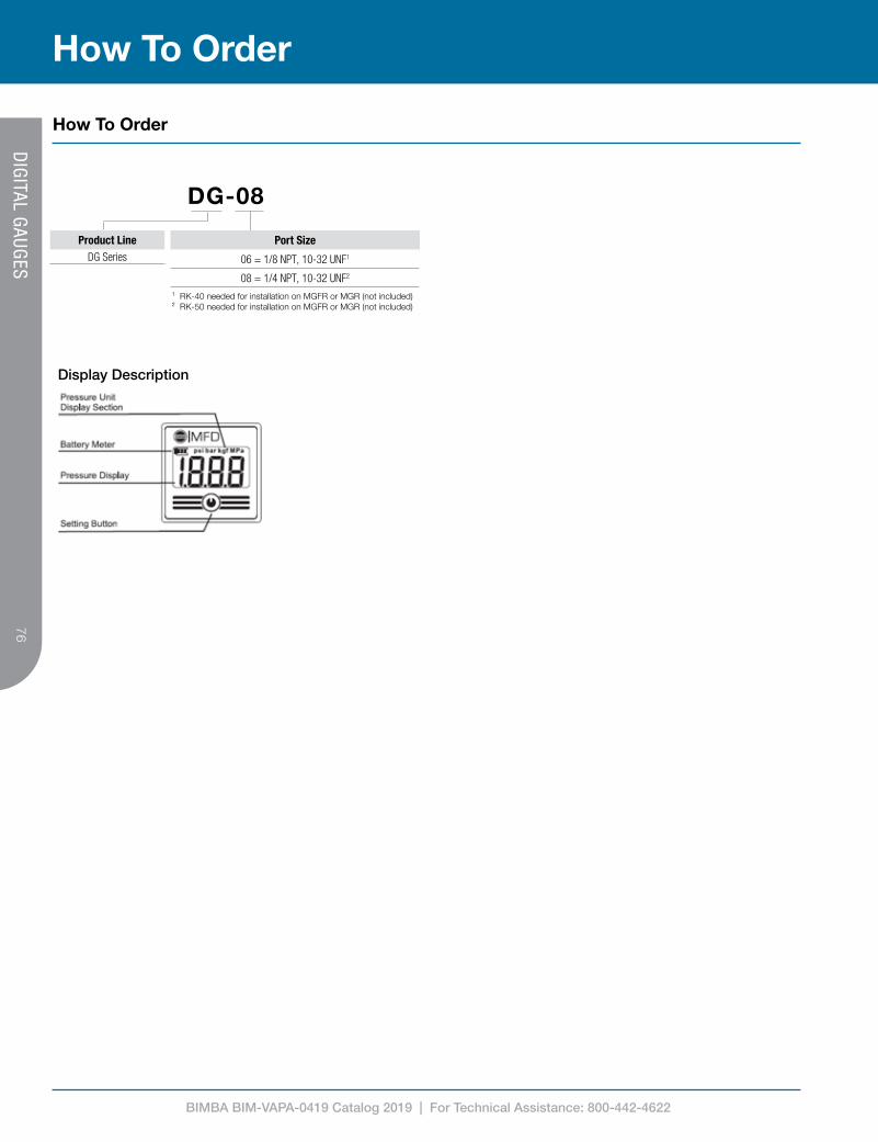
BIMBA BIM-VAPA-0419 Catalog 2019 | For Technical Assistance: 800-442-4622
76
Display Description
DG-08
Product LineDG Series
¹ RK-40 needed for installation on MGFR or MGR (not included)² RK-50 needed for installation on MGFR or MGR (not included)
Port Size
06 = 1/8 NPT, 10-32 UNF1
08 = 1/4 NPT, 10-32 UNF2
How To Order
How To Order
DIG
ITAL GAUG
ES

BIMBA BIM-VAPA-0419 Catalog 2019 | For Technical Assistance: 800-442-4622
77
Model DPSP-A DPSP-B DPSP-C DPSP-D DPSP-E DPSP-F
Fluid Air or Inert Gas (Clean/Dry)
Rated Pressure Range 0 to 145 PSI (0 to 1.0 Mpa)
Proof Pressure 217 PSI (1.5 Mpa)
Pressure Setting Range -14.5 to 145 PSI (-0.1 to 1.0 Mpa)
Temperature Range 32 °F to 120 °F (0 °C to 50 °C)
Voltage 12 to 24 VDC +/- 10%, 10% max. ripple (P-P)
Current Consumption <= 40mA (no loads)
Digital Outputs
Type 2 - NPN (Sinking) 2 - PNP (Sourcing)
Max. Load 125mA (each)
Residual Voltage <= 1.5V
Response Time <= 2.5ms (user-selectable: 25ms, 100ms, 250ms, 500ms, 1000ms, 1500ms anti-chatter function)Short Circuit Protection Yes
Repeatability +/-0.2% F.S. +/-1 digit
Analog Output
Type 1-5V(+/- 2.5% F.S.)
4-20mA(+/- 2.5% F.S.) - 1-5V
(+/- 2.5% F.S.)4-20mV
(+/- 2.5% F.S.) -
Impedance ~1kΩ
20-250Ω(12V Supply),
50-600Ω(24V Supply)
- ~1kΩ
20-250Ω(12V Supply),
50-600Ω(24V Supply)
-
Linearity +/- 1% F.S. - +/- 1% F.S. -
Display
Type 3-1/2 digit, 7-segment (red, green, orange)
Resolution 0.001 Mpa, 0.01 kgf/cm2, 0.01 bar, 0.1 PSI
Switch Indicator One per digital output
Refresh Rate ~0.2s
Indicator Accuracy +/-2% F.S. +/-1 digit at 77+/-5 °F (25+/-3 °C)
Enclosure Rating IP65 (with breather tube installed)
Storage Temperature Rating 14 °F to 140 °F (-10 °C to 60 °C)
Ambient Humidity Range 35 - 85% RH (no condensation)
Withstand Voltage 1000VAC for 1 min between case and lead wire
Insulation Resistance 50MΩ (at 500VDC between case and lead wire)
Vibration Resistance Total amplitude 1.5mm or 10g, 10Hz-55Hz-10Hz (one minute scan), two hours in X, Y, and Z
Shock 100m/s2 (10g), three times X, Y, and Z
Temperature Characteristic +/-2% F.S. of detected pressure at 77°F (25°C)
Included Cable Oil-resistant, 2m long
Weight 86g
Engineering Specifications
Analog Output Characteristics
Technical Data
DIG
ITAL PRESSURE SWITCH
ES
Product Features
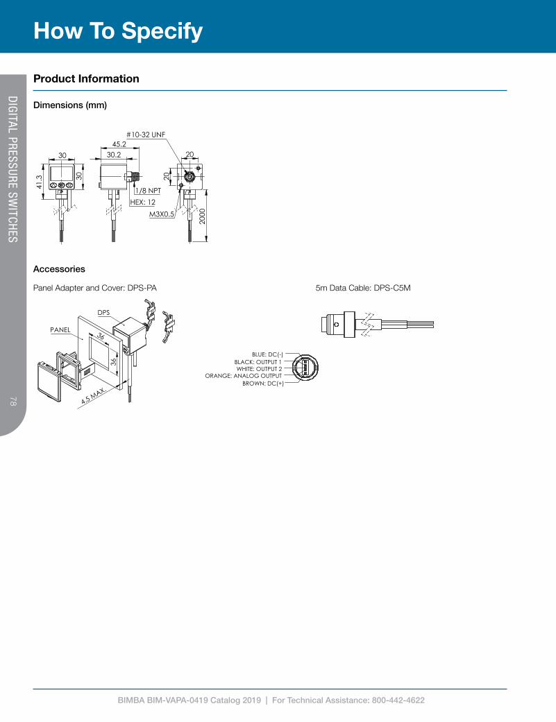
BIMBA BIM-VAPA-0419 Catalog 2019 | For Technical Assistance: 800-442-4622
78
Product Information
Dimensions (mm)
30
30
41.
3
30.2 45.2
HEX: 12
1/8 NPT
20
20
200
0
#10-32 UNF
M3X0.5
BLUE: DC(-)
WHITE: OUTPUT 2 BLACK: OUTPUT 1
ORANGE: ANALOG OUTPUT BROWN: DC(+)
36
36
4.5 MAX.
PANEL
DPS
DPS_-_-06-T
THIS DRAWING CONTAINS PROPRIETARY DESIGNS AND/OR INFORMATION OF BIMBA MFG. CO. OR ITS SUBSIDIARIES AND IS NOT TO BE TRANSMITTED, REPRODUCED, USED OR DISCLOSED WITHOUT WRITTEN PERMISSION OF BIMBA MFG. CO. OR ITS SUBSIDIARIES.
DESIGN REFLECTS OUR BEST ENGINEERING OPINION BASED ON WRITTEN APPLICATION SPECIFICATIONS RECEIVED. SUITABILITY OF A DESIGN FOR AN APPLICATION REQUIRES ANALYSIS AND/OR TESTS IN YOUR SPECIFIC SYSTEM.
Mead Fluid Dynamics, Inc.Chicago, IL. 60641
(877) MEAD USA [email protected]
PROPRIETARY DRAWING - Reference Only
Accessories
30
30
41.
3
30.2 45.2
HEX: 12
1/8 NPT
20
20
200
0
#10-32 UNF
M3X0.5
BLUE: DC(-)
WHITE: OUTPUT 2 BLACK: OUTPUT 1
ORANGE: ANALOG OUTPUT BROWN: DC(+)
36
36
4.5 MAX.
PANEL
DPS
DPS_-_-06-T
THIS DRAWING CONTAINS PROPRIETARY DESIGNS AND/OR INFORMATION OF BIMBA MFG. CO. OR ITS SUBSIDIARIES AND IS NOT TO BE TRANSMITTED, REPRODUCED, USED OR DISCLOSED WITHOUT WRITTEN PERMISSION OF BIMBA MFG. CO. OR ITS SUBSIDIARIES.
DESIGN REFLECTS OUR BEST ENGINEERING OPINION BASED ON WRITTEN APPLICATION SPECIFICATIONS RECEIVED. SUITABILITY OF A DESIGN FOR AN APPLICATION REQUIRES ANALYSIS AND/OR TESTS IN YOUR SPECIFIC SYSTEM.
Mead Fluid Dynamics, Inc.Chicago, IL. 60641
(877) MEAD USA [email protected]
PROPRIETARY DRAWING - Reference Only
30
30
41.
3
30.2 45.2
HEX: 12
1/8 NPT
20
20
200
0
#10-32 UNF
M3X0.5
BLUE: DC(-)
WHITE: OUTPUT 2 BLACK: OUTPUT 1
ORANGE: ANALOG OUTPUT BROWN: DC(+)
36
36
4.5 MAX.
PANEL
DPS
DPS_-_-06-T
THIS DRAWING CONTAINS PROPRIETARY DESIGNS AND/OR INFORMATION OF BIMBA MFG. CO. OR ITS SUBSIDIARIES AND IS NOT TO BE TRANSMITTED, REPRODUCED, USED OR DISCLOSED WITHOUT WRITTEN PERMISSION OF BIMBA MFG. CO. OR ITS SUBSIDIARIES.
DESIGN REFLECTS OUR BEST ENGINEERING OPINION BASED ON WRITTEN APPLICATION SPECIFICATIONS RECEIVED. SUITABILITY OF A DESIGN FOR AN APPLICATION REQUIRES ANALYSIS AND/OR TESTS IN YOUR SPECIFIC SYSTEM.
Mead Fluid Dynamics, Inc.Chicago, IL. 60641
(877) MEAD USA [email protected]
PROPRIETARY DRAWING - Reference Only
Panel Adapter and Cover: DPS-PA 5m Data Cable: DPS-C5M
How To Specify
DIG
ITAL PRESSURE SWITCH
ES

BIMBA BIM-VAPA-0419 Catalog 2019 | For Technical Assistance: 800-442-4622
79
How To Order
How To Order
DPS P-A-06-T
Product Line
DPS Series Pressure Range
P = (-14.5 to 145 PSI)
Output
A = 2 NPN digital, 1 (1-5V) analog
B = 2 NPN digital, 1 (4-20mA) analog
C = 2 NPN digital, copy function
D = 2 PNP digital, 1 (1-5V) analog
E = 2 PNP digital, 1 (4-20mA)
Port
06 = 1/8"
Thread
T = NPT
DIG
ITAL PRESSURE SWITCH
ES

BIMBA BIM-VAPA-0419 Catalog 2019 | For Technical Assistance: 800-442-4622
80
Notes

BIMBA BIM-VAPA-0419 Catalog 2019 | For Technical Assistance: 800-442-4622
81
Specialized pneumatic actuators provide unique motion profiles for uncommon applications across a variety of industries. Extruded thrusters and compact cylinders provide distinctive twists on common pneumatics, while rotary actuators and grippers fill roles that traditional motion profiles cannot.
Actuators

Contents83 Extruded Thrusters
83 – Engineering Specifications 83 – Materials 84 – Dimensions 86 – Maximum Recommended Loads 87 – How To Order
88 Compact Cylinders 88 – Engineering Specifications 88 – Materials 89 – Dimensions 91 – How To Order 92 – Brackets & Adapter
93 Rotary Actuators 93 – Engineering Specifications 93 – Torque Output 93 – Max Energy Absorbsion & Loads 94 – Dimensions 95 – How To Order
96 Parallel Grippers 96 – Engineering Specifications 96 – Gripping Force & Stroke 97 – Dimensions & Mounting Styles 98 – How To Order
99 Angular Grippers 99 – Engineering Specifications 99 – Gripping Force & Stroke 100 – Dimensions & Mounting Styles 101 – How To Order
102 Gripper Reference 102 – How It Works
103 Service Parts 103 – Dimensions, Description & Compatibility
104 Track Mounted Switch - Square Switch Tracks 104 – Engineering Specifications 104 – Dimensions & Wiring Diagrams 105 – How To Order
106 Track Mounted Switch - 4mm C-Slots 106 – Engineering Specifications 106 – Dimensions & Wiring Diagrams 106 – How To Order
107 Switch Selector Guide 107 – Descriptions, Bore Sizes 107 – Reed & Solid State Switch Availability

BIMBA BIM-VAPA-0419 Catalog 2019 | For Technical Assistance: 800-442-4622
83
Bore Size (mm) 12 16 20 25 32 40 50 63
Fluid Air (Clean/Dry)
Action Double Acting
Pressure Range 14 to 145 PSI (0.1 to 1.0 MPa)
Proof Pressure 215 PSI (1.5 MPa)
Temperature Range -4 °F to 158 °F (-20 °C to 70 °C)
Lubrication Not Required
Cushion Type Bumper
Speed Range 30 to 500 mm/s
Stroke Tolerance +1.0 / -0
Non-Rotating Tolerance
Linear Bushing (MTCL) ± 0.08° ± 0.07° ± 0.06° ± 0.05°
Brass Bushing (MTCM) ± 0.10° ± 0.09° ± 0.08° ± 0.06°
Port Size M5X0.8 1/8NPT 1/4NPT
Sensor Switch Compatibility1
Reed Switch MCS1-G
Solid State Switch MDS1-G
11
14
20
15
17
13
2
21
18
19
3
22
16
5
4
1
9
8
6
7
12
23
10
Item 23 forBore Size ≥50mm
No. Item Material No. Item Material
1 Tooling Plate Free-Machining Steel 13 O-Ring NBR
2 Guide Shaft SAE440/SUS440C Steel; Chrome Plated 14 O-Ring NBR
3 Body Aluminum; 6463-T5; Anodized 15 Rear Cap Brass; Ni Plated
4 Retaining Ring Spring Steel 16 Piston Rod Carbon Steel; Chrome Plated
5 Rod Guide Brass; Ni Plated 17 Piston Brass; Ni Plated
6 Bumper Urethane 18 Magnet Seat Brass; Ni Plated
7 Rod Seal NBR 19 Magnet Washer NBR
8 Screw Stainless Steel 20 Magnet Sintered Metal (Neodymium)
9 O-Ring NBR 21 Plug Carbon Steel; Zinc Plated
10 Screw/Rivet2 Stainless Steel 22Auxiliary Port
PlugCarbon Steel; Zinc Plated
11 BearingMTCM: Bronze
MTCL: Steel Ball23 Rod Bearing Bronze (50mm and 63mm only)
12 Retaining Ring Spring Steel 24 Spacer Aluminum Alloy
² Item number 10 on MTCL-12 and MTCL-16 thrusters are screws. All other thrusters are rivets.
¹ See page 104-105 for switch specifications
Product Features
Technical Data
Engineering Specifications
Materials
B B
Type Bore Size Stroke
MTCL12, 16 ≤30mm
20 ~ 63 ≤50mmMTCM 12 ~ 63 ≤50mm
Type Bore Size Stroke
MTCLØ12 ~ Ø16 ≤30mm
Ø20 ~ Ø63 ≤50mm
MTCM Ø12 ~ Ø63 ≤50mm
C C
SECTION C-C SCALE 1 : 2
Type Bore Size Stroke
MTCL12 ~ 16 30<Stroke≤100mm20 ~ 63 50<Stroke≤100mm
MTCM 12 ~ 63 50<Stroke≤100mm
Type Bore Size Stroke
MTCLØ12 ~ Ø16 30<Stroke≤100mm
Ø20 ~ Ø63 50<Stroke≤100mm
MTCM Ø12 ~ Ø63 50<Stroke≤100mm
C C
SECTION C-C SCALE 1 : 2
24
Type Bore Size StrokeMTCL 12 ~ 63 >100mmMTCM 12 ~ 63 >100mm
Type Bore Size StrokeMTCL Ø12 ~ Ø63 >100mm
MTCM Ø12 ~ Ø63 >100mm
EXTRUD
ED TH
RUSTERS

BIMBA BIM-VAPA-0419 Catalog 2019 | For Technical Assistance: 800-442-4622
84
How To Specify
Product Information
Dimensions (mm)
GB GD+STROKE
GC
(2) P1PLUGGED
J
(2) D
R RR
N NN
FA GE
FB
GA
C+STROKE B+STROKE
E
A+STROKE
(2) P1
(4) P THRUT x TL DEEP
YRAM DIAMETER
H
WA
R
W WB
(4) MM x ML DEEP
V
SEE SECTION B-B
A
K SEE SECTION B-B
R
NN N
(4) M x LL DEEP
WL
QL
R
(4) MM x THRU PLATE
SEE SECTION B-B
Q WW
B
B
VB
VA
VD
VC
VE
DETAIL A
L1
PP
PA
L2
PARTIALSECTION B-B
EXTRUD
ED TH
RUSTERS

BIMBA BIM-VAPA-0419 Catalog 2019 | For Technical Assistance: 800-442-4622
85
Dimensions (mm)
Product Information
How To SpecifyEXTR
UDED
THR
USTERS
Stroke (mm)Bore Size (mm)
12 16 20 25
A
0-30 42 46 53 53.531-100 55 65 80 82101-200 85 95 104 104.5
201+ - - 122 122B 42 46 53 53.5C 29 33 37 37.5
D 6 (MTCL)8 (MTCM)
8 (MTCL)10 (MTCM)
10 (MTCL)12 (MTCM)
12 (MTCL)16 (MTCM)
E
0-30 0 0 0 0
31-50 13 (MTCL)0 (MTCM)
19 (MTCL)0 (MTCM)
27 (MTCL)0 (MTCM)
28.5 (MTCL)0 (MTCM)
51-100 13 19 27 28.5101-200 43 49 51 51
201+ - - 69 68.5FA 8 8 10 10FB 13 13 16 16GA 7.5 8 9 9GB 11 11 10.5 11.5GC 8 10 10.5 13.5GD 13 15 12.5 12.5GE 11 11 10.5 11.5H 58 64 83 93J 18 19 25 28.5
K
0-30 15 17 29 2931-100 25 27 39 39
101-200 60 60 77 77201+ - - 117 117
LL 10 10 12 12L1 6 6 6 6L2 3 3 3 3M M5 X 0.8 M5 X 0.8 M6 X 1.0 M6 X 1.0ML 10 12 13 15MM M4 X 0.7 M5 X 0.8 M5 X 0.8 M6 X 1.0N 5 5 17 17
NN
0-30 20 24 24 2431-100 40 44 44 44
101-200 110 110 120 120201+ - - 200 200
P 4.5 4.5 5.5 5.5PA 3 3 3 4PP 3.5 3.5 3.5 4.5P1 M5 X 0.8 M5 X 0.8 1/8 NPT 1/8 NPTQ 14 16 18 26QL 48 54 70 78R 23 24 28 34
RR 41 46 54 64T 8 8 9.5 9.5TL 4.5 4.5 5.5 5.5V 37 38 44 50
VA 7.5 7.5 8.5 8.5VB 4.5 4.5 5.5 5.5VC 4 4 4.5 4.5VD 2 2.5 3 3VE 6.5 7 8 8.5W 26 30 36 42
WA 50 56 72 82WB 18 22 24 30WL 56 62 81 91WW 22 25 30 38
Y 6 8 10 12
Stroke (mm)Bore Size (mm)
32 40 50 63
A
0-50 65 (MTCL)78 (MTCM)
66 (MTCL)78 (MTCM)
76 (MTCL)89 (MTCM)
77 (MTCL)89 (MTCM)
51-100 102 102 118 118101-200 118 118 134 134
201+ 140 140 161 161B 59.5 66 72 77C 37.5 44 44 49
D 16 (MTCL)20 (MTCM)
16 (MTCL)20 (MTCM 20 20
E
0-50 5.5 (MTCL)18.5 (MTCM)
0 (MTCL)12 (MTCM)
4 (MTCL)17 (MTCM)
0 (MTCL)12 (MTCM)
51-100 42.5 36 46 41101-200 58.5 52 62 57
201+ 80.5 74 89 84FA 12 12 16 16FB 22 22 28 28GA 9 10 11 13.5GB 12.5 14 12 16.5GC 15 18 21.5 28GD 7 13 9 14GE 12.5 14 14 16.5H 112 120 148 162J 34 38 47 55
K
0-40 33 34 36 3841-100 45 46 48 50101-200 83 84 86 88
201+ 121 122 124 124LL 16 16 20 20L1 6 6 8 8L2 3 3 4 4M M8 X 1.25 M8 X 1.25 M10 X 1.5 M10 X 1.5ML 20 20 22 22MM M8 X 1.25 M8 X 1.25 M10 X 1.5 M10 X 1.5N 21 22 24 24
NN
0-40 24 24 24 2841-100 48 48 48 52101-200 124 124 124 128
201+ 200 200 200 200P 6.5 6.5 8.5 8.5
PA 4 4 5 5PP 4.5 4.5 6 6P1 1/8 NPT 1/8 NPT 1/4 NPT 1/4 NPTQ 30 30 40 50QL 96 104 130 130R 42 50 66 80
RR 78 86 110 124T 11 11 14 14TL 7.5 7.5 9 9V 63 72 92 110
VA 10.5 10.5 13.5 18VB 6.5 6.5 8.5 11VC 5.5 5.5 7.5 10VD 3.5 4 4.5 7VE 9.5 11 13.5 18.5W 48 54 64 78
WA 98 106 130 142WB 34 40 46 58WL 110 118 146 158WW 44 44 60 70
Y 16 16 20 20

BIMBA BIM-VAPA-0419 Catalog 2019 | For Technical Assistance: 800-442-4622
86
How To Specify
Product Information
Bore Size (mm)
Type
Maximum Side Load (N)
Stroke (mm)
10 20 25 30 40 50 60 70 75 80 90 100 125 150 175 200 225 250
12MTCM 44 33 29 26 41 36 30 28 26 25 24 22 19 17 - - - -
MTCL 37 27 25 22 35 30 27 24 23 21 19 18 15 12 - - - -
16MTCM 67 51 42 37 63 58 49 41 37 35 33 32 27 24 22 20 - -
MTCL 54 40 37 32 54 47 42 38 35 32 30 28 23 20 17 15 - -
20MTCM - 78 61 57 123 112 99 91 87 84 79 75 66 59 54 49 45 42
MTCL - 58 52 48 101 90 83 74 70 69 63 58 62 54 48 43 39 35
25MTCM - 93 89 76 142 131 119 107 101 97 90 85 68 79 71 65 61 55
MTCL - 82 79 68 132 118 109 99 93 88 81 77 80 70 62 55 50 45
32MTCM - - 203 190 179 164 221 197 182 172 163 157 142 127 116 106 98 91
MTCL - - 191 182 166 157 207 178 164 156 150 144 203 186 171 158 146 137
40MTCM - - 203 190 179 164 221 197 182 172 163 159 142 127 116 106 97 91
MTCL - - 190 182 166 157 210 179 163 156 150 144 203 185 171 158 146 137
50MTCM - - 296 283 268 245 303 288 273 266 253 241 216 195 179 164 155 142
MTCL - - 208 196 185 173 259 232 223 212 207 199 264 242 224 207 195 181
63MTCM - - 296 283 268 245 303 288 273 266 253 241 216 195 179 164 153 142
MTCL - - 206 196 180 171 259 232 221 212 205 196 262 240 221 205 191 178
Bore Size (mm)
Type
Maximum Torque (Nm)
Stroke (mm)
10 20 25 30 40 50 60 70 75 80 90 100 125 150 175 200 225 250
12MTCM 0.90 0.79 0.71 0.65 0.77 0.72 0.65 0.53 0.50 0.47 0.41 0.36 0.31 0.27 - - - -
MTCL 0.61 0.45 0.40 0.35 0.58 0.50 0.44 0.39 0.37 0.35 0.32 0.29 0.24 0.20 - - - -
16MTCM 1.21 1.04 0.94 0.88 1.23 1.11 0.99 0.72 0.69 0.65 0.61 0.58 0.50 0.44 0.40 0.36 - -
MTCL 0.99 0.74 0.66 0.59 0.99 0.86 0.77 0.69 0.65 0.61 0.57 0.52 0.43 0.37 0.32 0.28 - -
20MTCM - 1.57 1.42 1.31 2.39 2.15 1.97 1.90 1.88 1.86 1.72 1.63 1.44 1.28 1.16 1.06 1.01 0.90
MTCL - 1.26 1.14 1.03 2.17 1.94 1.79 1.59 1.52 1.46 1.33 1.25 1.34 1.17 1.03 0.93 0.88 0.76
25MTCM - 2.40 2.22 2.01 3.66 3.35 3.17 3.06 2.96 2.91 2.77 2.57 2.26 2.02 1.83 1.67 1.57 1.42
MTCL - 2.11 1.96 1.75 3.37 3.02 2.71 2.42 2.38 2.33 2.19 1.97 2.05 1.78 1.58 1.41 1.22 1.16
32MTCM - - 6.35 6.00 5.73 5.13 5.98 5.74 5.69 5.62 5.11 4.97 4.42 3.98 3.61 3.31 2.97 2.84
MTCL - - 5.95 5.73 5.44 4.89 5.43 5.15 5.11 5.02 4.70 4.51 6.34 5.79 5.33 4.93 4.33 4.29
40MTCM - - 7.00 6.60 6.11 5.66 6.66 6.31 6.27 6.23 5.86 5.48 4.87 4.38 3.98 3.65 3.34 3.13
MTCL - - 6.55 6.21 5.77 5.39 6.17 5.67 5.62 5.58 5.33 4.96 6.98 6.38 5.87 5.43 5.00 4.72
50MTCM - - 13.0 12.6 11.0 10.8 13.7 12.7 12.0 11.8 11.1 10.8 9.50 8.60 7.86 7.24 6.80 6.24
MTCL - - 9.17 8.75 8.30 7.62 10.3 9.94 9.83 9.77 8.82 8.74 11.6 10.7 9.83 9.12 8.95 7.95
63MTCM - - 14.7 13.6 12.9 12.1 19.4 16.2 13.5 12.7 12.1 11.9 10.7 9.69 8.86 8.16 7.52 7.04
MTCL - - 10.2 9.74 9.20 8.48 17.5 14.0 11.0 10.6 10.2 9.74 13.0 11.9 11.0 10.2 9.63 8.84
N x 0.225 = LBSNm x 8.85 = IN-LBS
Torque: T (Nm)
F
F
Note: F applied at full extention
Maximum Recommended Loads
EXTRUD
ED TH
RUSTERS

BIMBA BIM-VAPA-0419 Catalog 2019 | For Technical Assistance: 800-442-4622
87
How To Order
How To Order
Stroke (mm)Bore Size (mm)
12 16 20 25 32 40 50 6310 X X20 X X X X25 X X X X X X X X30 X X X X X X X X40 X X X X X X X X50 X X X X X X X X60 X X X X X X X X70 X X X X X X X X75 X X X X X X X X80 X X X X X X X X90 X X X X X X X X
100 X X X X X X X X125 X X X X X X X X150 X X X X X X X X175 X X X X X X X200 X X X X X X X225 X X X X X X250 X X X X X X
MTC M-16 x 70-S-T
Product
MTC Extruded ThrusterMagnet
S = with Magnet
Ports
T = Standard1
¹ See page 83 for the Port Sizes listed in the Engineering Specifications table.
Brushing Type
M = Bronze Bushing
L = Linear Ball Bushing
EXTRUD
ED TH
RUSTERS

BIMBA BIM-VAPA-0419 Catalog 2019 | For Technical Assistance: 800-442-4622
88
Bore Size (mm) 12 16 20 25 32 40 50 63 80 100
Fluid Air (Clean/Dry)
Action Double Acting
Pressure Range 14 to 145 PSI (0.1 to 1.0 MPa)
Proof Pressure 215 PSI (1.5 MPa)
Temperature Range -4 °F to 176 °F (-20 °C to 80 °C)
Cushion Type Bumper
Speed Range 30 to 500 mm/s
Stroke Tolerance +1.0 / -0
Port Size M5 X 0.8 1/8 NPT 1/4 NPT 3/8 NPT
Thrust,N (lbs)1
Pushing Force 68(15)
121(27)
189(42)
295(66)
483(108)
754(169)
1178(264)
1870(420)
3016(678)
4712(1059)
Pulling Force 51(11)
91(20)
141(32)
227(51)
362(81)
633(142)
990(222)
1682(378)
2721(611)
4230(950)
Sensor Switch Compatibility2
Reed Switch MCS1-G
Solid State Switch MDS1-G
¹ Thrust at 0.6 MPa (87psi) inlet pressure.² See pages 104-105 for switch specifications.See page 92 for male thread adapter.
Product Features
Technical Data
Engineering Specifications
B
B
SECTION B-B
5
6
3
8
9 11 12 13 1416
17
15
18
MEAD FLUID DYNAMICS
UNLESS OTHERWISE SPECIFIED
DIMENSIONS ARE IN INCHES
TOLERANCES ARE:
xxx = ±.005 xx = ±.010
MATERIAL & SPECIFICATION
TITLE:
THE INFORMATION CONTAINED IN THIS DRAWING IS THE SOLE PROPERTY OFMEAD FLUID DYNAMICS. ANY REPRODUCTION IN PART OR WHOLE WITHOUTTHE WRITTEN PERMISSION OF MEAD FLUID DYNAMICS IS PROHIBITED.
XXXXXXX
XXXXXXX
DES: DR: AP: DATE:
DWG. NO.
SolidWorksDWG.
DWGSIZE A
SHEET 1OF 1
SCALE:
XXXXXXXFINISH:
DO NOT SCALE REV No.
SURFACEFINISH
ANGLES
ROUNDNESS
FLATNESS
PARALLELISM
32
± 1/2
RUN OUT
PERPEND.
CONCENTRICITY
ER No. BY DATE
DWG. NO.XXXXXXX
XX XXXXXXX
XX
X XXX-XXXXXX XX SEE AGILE
XXXXXXX
AA
SECTION A-A
5
6
3
8
9
2
10 1211 13 14 15
18
16
17
MEAD FLUID DYNAMICS
UNLESS OTHERWISE SPECIFIED
DIMENSIONS ARE IN INCHES
TOLERANCES ARE:
xxx = ±.005 xx = ±.010
MATERIAL & SPECIFICATION
TITLE:
THE INFORMATION CONTAINED IN THIS DRAWING IS THE SOLE PROPERTY OFMEAD FLUID DYNAMICS. ANY REPRODUCTION IN PART OR WHOLE WITHOUTTHE WRITTEN PERMISSION OF MEAD FLUID DYNAMICS IS PROHIBITED.
XXXXXXX
XXXXXXX
DES: DR: AP: DATE:
DWG. NO.
SolidWorksDWG.
DWGSIZE A
SHEET 1OF 1
SCALE:
XXXXXXXFINISH:
DO NOT SCALE REV No.
SURFACEFINISH
ANGLES
ROUNDNESS
FLATNESS
PARALLELISM
32
± 1/2
RUN OUT
PERPEND.
CONCENTRICITY
ER No. BY DATE
DWG. NO.XXXXXXX
XX XXXXXXX
XX
X XXX-XXXXXX XX SEE AGILE
XXXXXXX
AA
SECTION A-A
5
6
3
8 9
2
10 1211 13 14 15
18
16
17
1
7
4
MEAD FLUID DYNAMICS
UNLESS OTHERWISE SPECIFIED
DIMENSIONS ARE IN INCHES
TOLERANCES ARE:
xxx = ±.005 xx = ±.010
MATERIAL & SPECIFICATION
TITLE:
THE INFORMATION CONTAINED IN THIS DRAWING IS THE SOLE PROPERTY OFMEAD FLUID DYNAMICS. ANY REPRODUCTION IN PART OR WHOLE WITHOUTTHE WRITTEN PERMISSION OF MEAD FLUID DYNAMICS IS PROHIBITED.
XXXXXXX
XXXXXXX
DES: DR: AP: DATE:
DWG. NO.
SolidWorksDWG.
DWGSIZE A
SHEET 1OF 1
SCALE:
XXXXXXXFINISH:
DO NOT SCALE REV No.
SURFACEFINISH
ANGLES
ROUNDNESS
FLATNESS
PARALLELISM
32
± 1/2
RUN OUT
PERPEND.
CONCENTRICITY
ER No. BY DATE
DWG. NO.XXXXXXX
XX XXXXXXX
XX
X XXX-XXXXXX XX SEE AGILE
XXXXXXXAA
SECTION A-A
5
6
3
8 9 10 1211 13 14 15
18
16
17
7
4
MEAD FLUID DYNAMICS
UNLESS OTHERWISE SPECIFIED
DIMENSIONS ARE IN INCHES
TOLERANCES ARE:
xxx = ±.005 xx = ±.010
MATERIAL & SPECIFICATION
TITLE:
THE INFORMATION CONTAINED IN THIS DRAWING IS THE SOLE PROPERTY OFMEAD FLUID DYNAMICS. ANY REPRODUCTION IN PART OR WHOLE WITHOUTTHE WRITTEN PERMISSION OF MEAD FLUID DYNAMICS IS PROHIBITED.
XXXXXXX
XXXXXXX
DES: DR: AP: DATE:
DWG. NO.
SolidWorksDWG.
DWGSIZE A
SHEET 1OF 1
SCALE:
XXXXXXXFINISH:
DO NOT SCALE REV No.
SURFACEFINISH
ANGLES
ROUNDNESS
FLATNESS
PARALLELISM
32
± 1/2
RUN OUT
PERPEND.
CONCENTRICITY
ER No. BY DATE
DWG. NO.XXXXXXX
XX XXXXXXX
XX
X XXX-XXXXXX XX SEE AGILE
XXXXXXX
Stroke ≤100mm, No Magnet Stroke ≤100mm, With Magnet Stroke >100mm, No Magnet Stroke >100mm, With Magnet
Materials
Number Item Material
1 Washer No Washer (Ø12-Ø25 and Ø32-Ø100 with stroke ≤100mm); NBR (Ø32-Ø100 with stroke >100mm)2 Magnet Sintered Metal (Neodymium-Iron-Boron) (Ø12-Ø25); Plastic (Ø32-Ø100)3 Piston Brass (Ø12, Ø16); Aluminum Alloy (Ø20-Ø100)4 O-Ring NBR5 Back Cap Cap incorporated into body (Ø12, Ø16); Hard Anodized Aluminum Alloy6 Bumper TPU (Ø12-Ø25); NBR (Ø32-Ø100)7 Retaining Ring Spring Steel8 Wear Ring No Wear Ring (Ø12-Ø32); Polymer Bearing Material (Ø40-Ø100)9 Piston Seal NBR
10 Magnet Holder Brass (Ø12, Ø16); Aluminum Alloy (Ø20-Ø100)11 Piston Rod Carbon Steel with 20µm Chrome Plating12 Body Hard Anodized Aluminum Alloy13 Bumper NBR14 Bearing No Bearing (Ø12-Ø32); Bearing Alloy (Ø40-Ø100)15 O-Ring NBR16 Retaining Ring Spring Steel17 Rod Seal NBR18 Front Cap Aluminum Alloy
COM
PACT CYLIND
ERS

BIMBA BIM-VAPA-0419 Catalog 2019 | For Technical Assistance: 800-442-4622
89
How To Specify
Product Information
Dimensions (mm)
Ø12, Ø16
Ø20, Ø25
J+STROKE K L+STROKE
M1
M2 M2
M1
T
V1 V2
R
R1
(2) U
B
C
F X G DEEP
(4) E THRU
DFLATS
B
H
F X G DEEP D
FLATS
(2) E THRU
M2
M1
K L+STROKE J+STROKE
M1
M2
R
R1 T
(2) U V1 V2
B C
DFLATS
F X G DEEP
(4) E THRU
B D
FLATS
(2) E THRU
F X G DEEP
H
No Magnet Magnet
J+STROKE K L+STROKE
M1
M2 M2
M1
T
V1 V2
R
R1
(2) U
B
C
F X G DEEP
(4) E THRU
DFLATS
B
H
F X G DEEP D
FLATS
(2) E THRU
M2
M1
K L+STROKE J+STROKE
M1
M2
R
R1 T
(2) U V1 V2
B C
DFLATS
F X G DEEP
(4) E THRU
B D
FLATS
(2) E THRU
F X G DEEP
H
No Magnet Magnet
Ø32 - Ø100 (Stroke ≤ 100)
J+STROKE
K L+STROKE
M1 M1
M2 M2
T
R1 R
V1 V2
(2) U
DFLATS
C
B
A
(4) E THRU
F X G DEEP
N
K
M3 M3
L+STROKE
J+STROKE
S T
V1 V2
(2) U
R1
DFLATS
C B
A
(4) E THRU
F X G DEEP
Ø32 - Ø100 (Stroke > 100)
J+STROKE
K L+STROKE
M1 M1
M2 M2
T
R1 R
V1 V2
(2) U
DFLATS
C
B
A
(4) E THRU
F X G DEEP
N
K
M3 M3
L+STROKE
J+STROKE
S T
V1 V2
(2) U
R1
DFLATS
C B
A
(4) E THRU
F X G DEEP
COM
PACT CYLIND
ERS

BIMBA BIM-VAPA-0419 Catalog 2019 | For Technical Assistance: 800-442-4622
90
How To Specify
Product Information
Dimensions (mm)
* No Magnet** With Magnet See page 92 for male thread adapter.
Stroke (mm)Bore Size (mm)
12 16 20 25 32 40 50 63 80 100
A - - - - 49.5 57 71 84 104 123.5B 25 29 36 40 45 53 64 77 98 117C 15.5 20 25.5 28 34 40 50 60 77 94D 5 6 8 10 14 14 17 17 22 27E 3.4 3.4 5.2 5.2 5.2 5.2 6.8 8.5 10.3 10.3F M3 X 0.5 M4 X 0.7 M5 X 0.8 M6 X 1.0 M8 X 1.25 M8 X 1.25 M10 X 1.5 M10 X 1.5 M16 X 2.0 M20 X 2.5
G5-100 6 8 7 12 13 13 15 15 20 26125+ - - - - 13 13 15 15 21 27
H 22 28 36 40 - - - - - -
J
5-50 20.5*31.5**
22*34**
24*36**
27.5*37.5**
30*40**
36.5*46.5**
38.5*48.5**
44*54**
53.5*63.5**
65*75**
75-100 - - 34*36** 37.5 40 46.5 48.5 54 63.5 75
125+ - - - - 62.5 72 73.5 75 86 97.5
K5-50 3.5 3.5 4.5 5 7 7 8 8 10 12125+ - - - - 17 17 18 18 20 22
L
5-50 17*28**
18.5*30.5**
19.5*31.5**
22.5*32.5**
23*33**
29.5*39.5**
30.5*40.5**
36*46**
43.5*53.5**
53*63**
75-100 - - 29.5*31.5** 32.5 33 39.5 40.5 46 53.5 63
125+ - - - - 45.5 55 55.5 57 66 75.5M1 11 11 17 17 17 17 22 28.5 35.5 35.5M2 3.5 3.5 7 7 7 7 8 10.5 13.5 13.5M3 - - - - 17 17 22 27 32 33
N5-100 - - - - - - - - - -125+ - - - - 12 12 13 13 15 17
P 3.5 3 4 4.5 6 6 6.5 6.5 8.5 9.5R 5-100 6.5 6.5 9 9 9 9 11 14 17.5 17.5
R1 M4 X 0.7 M4 X 0.7 M6 X 1.0 M6 X 1.0 M6 X 1.0 M6 X 1.0 M8 X 1.25 M10 X 1.5 M12 X 1.75 M12 X 1.75
S5-100 - - - - - - - - - -125+ - - - - 22 28 35 35 43 59
T 6 8 10 12 16 16 20 20 25 32U M5 X 0.8 M5 X 0.8 M5 X 0.8 M5 X 0.8 1/8 NPT 1/8 NPT 1/4 NPT 1/4 NPT 3/8 NPT 3/8 NPT
V1
5 7.5*9**
8*9.5**
9*9.5* 11 7.5*
10.5** 11 9*10.5**
14*15** 16 20
10-100 7.5*9**
8*9.5**
9*9.5** 11 10.5 11 10.5 15 16 20
125+ - - - - 12.5 14 14 16.5 19 23
V2
5 5*7** 5.5 5.5 5.5 6.5*
7.5** 8 9*10.5**
9.5*10.5** 14 17.5
10-100 5*7** 5.5 5.5 5.5 7.5 8 10.5 10.5 14 17.5
125+ - - - - 12.5 14 14 16.5 19 23
COM
PACT CYLIND
ERS

BIMBA BIM-VAPA-0419 Catalog 2019 | For Technical Assistance: 800-442-4622
91
How To Order
How To Order
MACQ-16 x 30-S-T
Product
MACQ Compact CylinderMagnet
Blank = No Magnet
S = with Magnet
Ports
T = Standard1
¹ See page 88 for the Port Sizes listed in the Engineering Specifications table.
Stroke (mm)Bore Size (mm)
12 16 20 25 32 40 50 63 80 1005 X X X X X X X X X X
10 X X X X X X X X X X15 X X X X X X X X X X20 X X X X X X X X X X25 X X X X X X X X X X30 X X X X X X X X X X40 X X X X X X X X X X50 X X X X X X X X X X75 X X X X X X X X
100 X X X X X X X X125 X X X X X X150 X X X X X X
COM
PACT CYLIND
ERS

BIMBA BIM-VAPA-0419 Catalog 2019 | For Technical Assistance: 800-442-4622
92
(4) A
B
C
D
E
G
H
FHOLE
J
(4) A C
B
D
E
H
G
FHOLE
J
Ø12 - Ø25
Model A B C D E F G H JF-MACQ-12-CB 4.5 25 15.5 5.3 9.8 5 20 14 4
F-MACQ-16-CB 4.5 29 20 6.8 11.8 5 21 15 4
F-MACQ-20-CB 6.5 36 25.5 8.3 15.8 8 27 18 5
F-MACQ-25-CB 6.5 40 28 10.3 19.8 10 30 20 5
F-MACQ-32-CB 6.5 45.5 34 18.3 35.8 10 30 20 5.5
F-MACQ-40-CB 6.5 53.5 40 18.3 35.8 10 32 22 7
F-MACQ-50-CB 8.5 64.5 50 22.3 43.8 14 42 28 8
F-MACQ-63-CB 10.5 77.5 60 22.3 43.8 14 44 30 10
F-MACQ-80-CB 12.5 98.5 77 28.3 55.8 18 56 38 10
F-MACQ-100-CB 12.5 117.5 94 32.3 63.8 22 67 45 13
Pin, c-clips, and hardware included with all Clevis Brackets
How To Accessorize
Product Information
Clevis Brackets for MACQ Series
(4) A
B
C
D
E
G
H
FHOLE
J
(4) A C
B
D
E
H
G
FHOLE
J
Ø32 - Ø100
Ø12 - Ø25Rod Clevis Brackets for MACQ Series
E
F
G
H
B A
C
D
E
F
A B
C
D
H
G
J
AF
(2) AE
(2) AC
AA
AD
AB
Model A B C D E F G H J AA AB AC AD AE AFF-MACQ-12-Y 22 16 5 +.048/-0 9 5.3±0.1 6 10 M5 X 0.8 - 5 -.03/-.06 4 1.5 10.2 0.7 14.6
F-MACQ-16-Y 28 21 5 +.048/-0 11 6.6±0.1 11 12 M6 X 1.0 - 5 -.03/-.06 4 1.5 12.4 0.7 16.8
F-MACQ-20-Y 34 25 8 +.058/-0 15 8.3±0.1 8.5 16 M8 X 1.25 - 8 -.04/-.076 7 1.5 16.2 0.9 21
F-MACQ-25-Y 41 30 10 +.058/-0 19 10.3±0.1 10.5 20 M10 X 1.25 - 10 -.04/-.076 8 2 20.2 1.1 26.4
F-MACQ-32-Y 42 30 10 +.058/-0 22 18.4±0.1 16 22 M14 X 1.5 36 10 -.04/-.076 8 2 36.2 1.1 42.4
F-MACQ-40-Y 42 30 10 +.058/-0 22 18.4±0.1 16 22 M14 X 1.5 36 10 -.04/-.076 8 2 36.2 1.1 42.4
F-MACQ-50-Y 56 40 14 +.07/-0 28 22.4±0.1 20 28 M18 X 1.5 44 14 -.05/-.093 12 2 44.2 1.1 50.4
F-MACQ-63-Y 56 40 14 +.07/-0 28 22.4±0.1 20 28 M18 X 1.5 44 14 -.05/-.093 12 2 44.2 1.1 50.4
F-MACQ-80-Y 71 50 18 +.07/-0 38 28.4±0.1 23 38 M22 X 1.5 56 18 -.05/-.093 15 2 56.2 1.7 63.6
F-MACQ-100-Y 79 55 22 +.084/-0 44 32.4±0.1 22 44 M26 X 1.5 64 22 -.065/-.117 19 2.5 64.2 1.7 72.6
Pin, c-clips, and male adapter included with all Rod Clevis Brackets
Ø32 - Ø100
Male Adapter for MACQ Series
C B
F
E
D
AHEX
GFLATS
HHEX
Male Adapter includes jam nut (cylinder not included).
Model A B C D E F G H
F-MACQ-12-A 8 6 M5 X 0.8 14 10.5 4 5 2.5
F-MACQ-16-A 10 8 M6 X 1.0 15.5 12 5 6 3
F-MACQ-20-A 12 10 M8 X 1.25 18.5 14 6 8 4
F-MACQ-25-A 17 12 M10 X 1.25 22.5 17.5 6 10 5
F-MACQ-32-A 19 16 M14 X 1.5 28.5* / 38.5** 21.5 8 14 6
F-MACQ-40-A 19 16 M14 X 1.5 28.5* / 38.5** 21.5 8 14 6
F-MACQ-50-A 27 20 M18 X 1.5 33.5* / 43.5** 25.5 11 17 8
F-MACQ-63-A 27 20 M18 X 1.5 33.5* / 43.5** 25.5 11 17 8
F-MACQ-80-A 32 25 M22 X 1.5 43.5* / 53.5** 33.5 13 22 10
F-MACQ-100-A 36 32 M26 X 1.5 43.5* / 53.5** 31.5 13 27 10
* Stroke = 5 to 100 ** Stroke = 125, 150
COM
PACT CYLIND
ERS
E
F
G
H
B A
C
D
E
F
A B
C
D
H
G
J
AF
(2) AE
(2) AC
AA
AD
AB
E
F
G
H
B A
C
D
E
F
A B
C
D
H
G
J
AF
(2) AE
(2) AC
AA
AD
AB
E
F
G
H
B A
C
D
E
F
A B
C
D
H
G
J
AF
(2) AE
(2) AC
AA
AD
AB
(4) A
B
C
D
E
G
H
FHOLE
J
(4) A C
B
D
E
H
G
FHOLE
J

BIMBA BIM-VAPA-0419 Catalog 2019 | For Technical Assistance: 800-442-4622
93
Model 10 20 30 50
Fluid Air (Clean/Dry)
Action Double Rack and Pinion (Double Acting)
Pressure RangeBolt Adjustment 14 to 145 PSI (0.1 to 1.0 MPa)
Shock Absorber 14 to 87 PSI (0.1 to 0.6 MPa)
Proof Pressure 215 PSI (1.5 MPa)
Temperature Range 32 °F to 140 °F (0 °C to 60 °C)
Adjustment Angle Range 0° to 190° Rotation
Repeatable PrecisionBolt Adjustment 0.2°
Shock Absorber 0.05°
Rotation Times (s/90°)
Bolt Adjustment 0.2~1.0
Shock Absorber 0.2~0.7
Cushion TypeBolt Adjustment Rubber Bumper
Shock Absorber Shock Absorber
Port Size M5 X 0.8 Rear Ports 1/8 NPTSide Ports M5 X 0.8
Sensor Switch Compatibility1
Reed Switch MCS1-H
Solid State Switch MDS1-H
Includes Magnet
¹ See pages 106 for switch specifications
Loading Type MHRQ10 MHRQ20 MHRQ30 MHRQ50
Maximum allowed radial loading
80N(18lbs)
150N(33.7lbs)
200N(45lbs)
300N(67.4lbs)
Maximum allowed axial loading
80N(18lbs)
150N(33.7lbs)
200N(45lbs)
300N(67.4lbs)
Maximum allowed bending moment
2.5Nm(22.1in-lbs)
4.0Nm(35.4in-lbs)
5.5Nm(48.7in-lbs)
10.0Nm(88.5in-lbs)
Model With Bolt Adjustment With Shock AbsorberMHRQ10 0.01 0.04
MHRQ20 0.025 0.12
MHRQ30 0.05 0.12
MHRQ50 0.08 0.30
Product Features
Technical Data
Engineering Specifications
Torque Output Maximum Energy Absorbsion (J)
Maximum Loads
ROTARY ACTUATO
RS

BIMBA BIM-VAPA-0419 Catalog 2019 | For Technical Assistance: 800-442-4622
94
How To Specify
Product Information
Dimensions (mm)
J K
MAX AA
Y X
W
U
T
V
S R
P N
M
Z
(2) L SIDE PORT
CD DEEP H
E E 2
FG DEEP
FG DEEP
(2) AB DEEP
AP AP
AVAU DEEP
45°
ATAW DEEP
22.5°
AY
AZ
BA
BBBC DEEP
AVAU DEEP
BD
BG
BEBF DEEP
AMAN DEEP 2
2
(8) ARAS DEEPEQUALLYSPACED
AC AH
AG
AK AJ
AL
AF AE AB
(2) ADREAR PORT
Model A B C D E F G H J K L M N PMHRQ10 M8 X 1.25 12 15 +.043/-0 3 20 3 +.03/-0 3.5 5 29 M10 X 1.0 M5 X 0.8 4.5 46 +0/-0.062 45 +0/-0.062
MHRQ20 M10 X 1.5 15 17 +.043/-0 2.5 25 4 +.03/-0 4.5 9 30 M12 X 1.0 M5 X 0.8 6 61 +0/-0.074 60 +0/-0.074
MHRQ30 M10 X 1.5 15 22 +.052/-0 3 29 4 +.03/-0 4.5 9 34 M12 X 1.0 M5 X 0.8 6.5 67 +0/-0.074 65 +0/-0.074
MHRQ50 M12 X 1.75 18 26 +.052/-0 3 34 5 +.03/-0 5.5 10 38 M14 X 1.5 M5 X 0.8 10 77 +0/-0.074 75 +0/-0.074
Model AN AP AR AS AT AU AV AW AY AZ BA BB BC BD BE BF BGMHRQ10 8 28 M5 X 0.8 8 3 +.03/-0 3.5 3 +.03/-0 3.5 27 15 60 20 +.052/-0 4.5 32 11 6.5 6.5
MHRQ20 8 37 M6 X 1.0 10 4 +.03/-0 4.5 4 +.03/-0 4.5 34 20.5 76 28 +.052/-0 6.5 43 14 8.5 8.5
MHRQ30 8 40 M6 X 1.0 10 4 +.03/-0 4.5 4 +.03/-0 5 37 23 84 32 +.062/-0 5 48 14 8.5 8.5
MHRQ50 8 46 M8 X 1.25 12 5 +.03/-0 5.5 5 +.03/-0 6 50 26.5 100 35 +.062/-0 5.5 55 18 10.5 10.5
Model R S T U V W X Y Z AA AB AC AD AE AF AG AH AJ AK AL AM
MHRQ10 8 4.5 13 34 47 9.5 92 9.5 9.5 17.5* / 28.5** 13.5 34.5 M5 X 0.8 28 15.5 20.5 45 49.5 50 54.5 M5 X 0.8
MHRQ20 10 6.5 17 37 54 11 117 11 9.8 26* / 39** 12 47 M5 X 0.8 30 16 27.5 59 64.5 65 69.5 M6 X 1.0
MHRQ30 10 6.5 17 40 57 11.5 127 11.5 9.5 25.5* / 39** 13.5 50 1/8 NPT 32 18.5 29 64 69.5 70 74.5 M6 X 1.0
MHRQ50 12 7.5 20 46 66 15 152 15 14 31.5* / 51** 15 63 1/8 NPT 38 22 38 74.5 79.5 80 84.5 M8 X 1.25
* Bolt Adjustment** Shock Absorber
ROTARY ACTUATO
RS
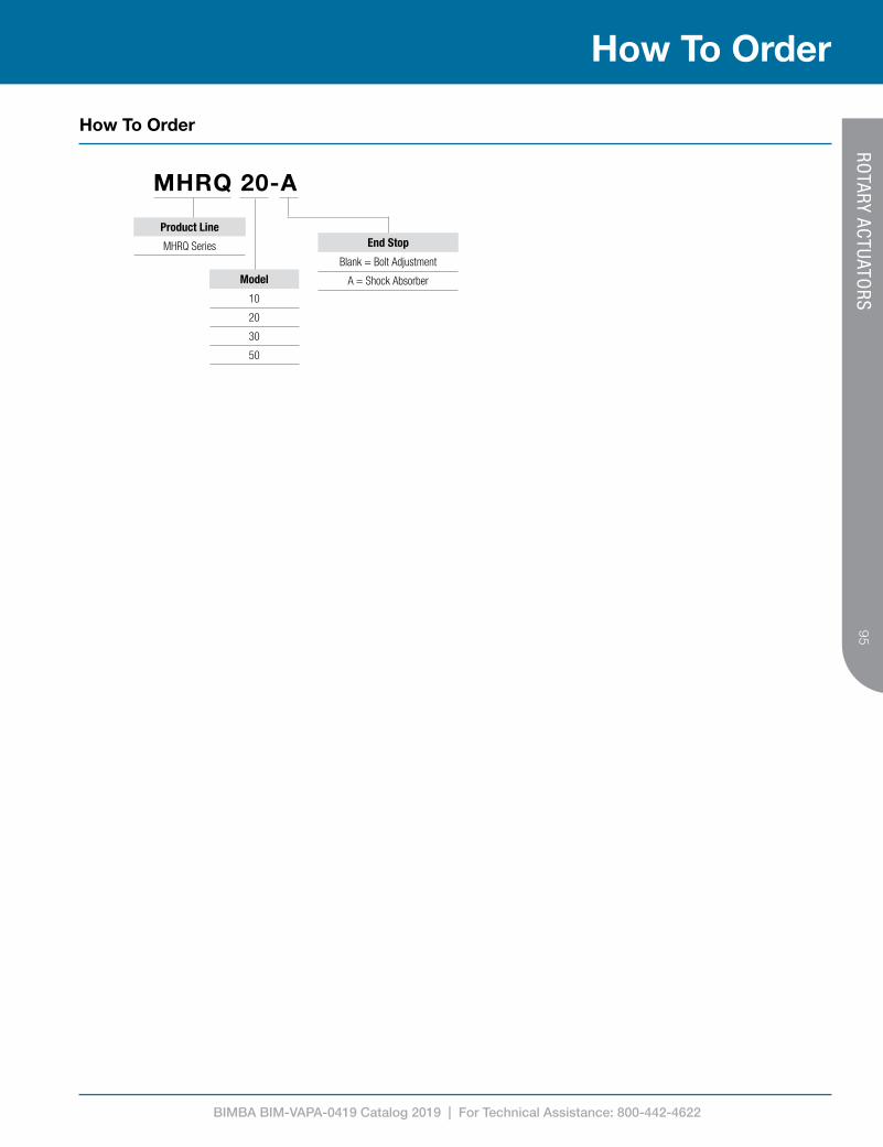
BIMBA BIM-VAPA-0419 Catalog 2019 | For Technical Assistance: 800-442-4622
95
How To Order
How To Order
MHRQ 20-A
Product Line
MHRQ Series
Model
10
20
30
50
End Stop
Blank = Bolt Adjustment
A = Shock Absorber
ROTARY ACTUATO
RS

BIMBA BIM-VAPA-0419 Catalog 2019 | For Technical Assistance: 800-442-4622
96
² Gripping force, F, measured with an operating pressure of 0.5MPa (72.5 PSI) at a gripping point of 20mm. See figure 1 on page 102.³ See figure 2 on page 102.
Model Double Acting (MHFK)
Bore Size (mm) 6 10 16 20 25 32 40
Gripping Force2, Fg (N)Closing3 3.3 11 34 45 69 160 255
Opening3 6.1 17 45 68 102 195 320
Closing/Opening Stroke (mm) 4 4 6 10 14 22 30
Weight (g)Standard 25 56 124 236 428 729 1268
Bottom 24 56 124 236 418 750 1340
Model Single Acting Normally Open (MHFTK)
Bore Size (mm) 6 10 16 20 25 32 40
Gripping Force2, Fg (N)Closing3 1.9 7 27 35 55 133 220
Opening3 - - - - - - -
Closing/Opening Stroke (mm) 4 4 6 10 14 22 30
Weight (g)Standard 26 57 125 238 430 778 1365
Bottom 25 57 125 238 420 799 1437
Model Single Acting Normally Closed (MHFSK)
Bore Size (mm) 6 10 16 20 25 32 40
Gripping Force2, Fg (N)Closing3 - - - - - - -
Opening3 3.7 13 38 59 87 163 270
Closing/Opening Stroke (mm) 4 4 6 10 14 22 30
Weight (g)Standard 26 57 125 238 430 778 1365
Bottom 25 57 125 238 420 799 1437
Bore Size (mm) 6 10 16 20 25 32 40
Fluid Air (Clean/Dry)
Pressure Range
Double Acting
6mm, 10mm 28 to 100 PSI (0.2 to 0.7 MPa)
16mm to 40mm 22 to 100 PSI (0.15 to 0.7 MPa)
Single Acting
6mm, 10mm 50 to 100 PSI (0.35 to 0.7 MPa)
16mm to 40mm 36 to 100 PSI (0.25 to 0.7 MPa)
Temperature Range -4 º F to 160 º F (-20 º C to 70 º C)
Lubrication Not Required
Repeatability ±0.01mm ±0.02mm
Maximum Frequency 180 Cycles/Min 60 Cycles/Min
Port Size M3x0.5 M5x0.8
Sensor Switch Compatibility1
Reed Switch MCS1-H MCS1-G, MCS1-H
Solid State Switch MDS1-H MDS1-G, MDS1-H
Includes Magnet
¹ See pages 104-107 for switch specifications
1 MPa = 145.04 PSI1 N = 0.225 lbf1 lbf = 453.6 g
Product Features
Technical Data
Engineering Specifications
Gripping Force and Stroke
PARALLEL GRIPPERS

BIMBA BIM-VAPA-0419 Catalog 2019 | For Technical Assistance: 800-442-4622
97
* Double Acting / ** Single Acting
Bore Size (mm) N P R S T U V W X Y Z AA AB
6 21 4 +0/-0.05 10 +/-0.05 - 7 +0.05/-0 1.5 - M2 X 0.4 M3 X 0.5 1.6 5.5 19 510 30 4 +0/-0.05 16.4 12 11 +0.05/-0 2 18 M2.5 X 0.45 M3 X 0.5 10 7.5 19 5.716 39 5 +0/-0.05 23.6 15 17 +0.05/-0 2 22 M3 X 0.5 M5 X 0.8 13 7.5 19 720 53 8 +0/-0.05 27.6 18 21 +0.05/-0 3 32 M4 X 0.7 M5 X 0.8 15 9.5 23 925 71 10 +0/-0.05 33.6 22 26 +0.05/-0 3.5 40 M5 X 0.8 M5 X 0.8 20 10 24 12
32 106 12 +0/-0.05 40 26 34 +0.05/-0 4 46 M6 X 1.0 M5 X 0.8 24 11 31*/40** 14
40 132 14 +0/-0.05 48 32 42 +0.05/-0 4 56 M8 X 1.25 M5 X 0.8 28 12 38*/50** 17
Bore Size (mm) A A1 A2 A3 B C D E F G H J K L M
6 - - - - - - 20 12 25.5 31 53 7.9 11 11 +2/-0 8 +0/-110 M3 X 0.5 6 5.5 6 11.5 27 23 16 23 37.5 57 6 12 15.5 +2/-0 11.5 +0/-116 M4 X 0.7 4.5 8 8 16 30 30.5 24 24.5 42.5 67.5 7.5 15 21 +2/-0 15 +0/-120 M5 X 0.8 8 10 10 18.5 35 42 30 29 53 84.5 9.5 20 26.5 +2/-0 16.5 +0/-125 M6 X 1.0 10 12 12 22 36.5 52 36 30 63.6 102.5 11 25 33.5 +2/-0 19.5 +0/-1
32 M6 X 1.0 10 13 13 26 48*/57** 60 46 40*/49** 67*/76** 113*/122** 12 29 48 +2.5/-0 26 +0/-1
40 M8 X 1.25 13 16 17 32 58*/71** 72 56 49*/62** 83*/96** 139*/152** 15 36 60 +2.5/-0 30 +0/-1
Bore Size (mm) AC AD AE AF AG AH AJ AK AL AM AN AP
6 2.5 4 +0/-0.05 2 3 3.5 7.5 - - 4 +1.5/-0 1.5 +0/-0.5 - 710 3 5 +0/-0.05 2.45 4 6 11 2 +0.025/-0 4.5 5.5 +2/-0 1.5 +0/-0.5 2 516 4 8 +0/-0.05 3.05 6 8 14 2.5 +0.025/-0 5.8 7.5 +2/-0 1.5 +0/-0.5 2.5 820 5 10 +0/-0.05 3.95 8 10 18 3 +0.025/-0 7.5 11.5 +2/-0 1.5 +0/-0.5 3 10.525 6 12 +0/-0.05 4.9 10 12 22 4 +0.030/-0 9 16 +2.5/-0 2 +0/-0.5 4 1332 7 15 +0/-0.05 7.3 12 20 34.5 5 +0.030/-0 14.8 25 +2.5/-0 3 +0/-0.5 5 1840 9 18 +0/-0.05 8.7 16 24 41.5 6 +0.030/-0 17.7 33 +3/-0 3 +0/-0.5 6 22
Standard Mounting Style Bottom Mounting StyleDimensionally same as Standard except as shown
Product Information
Dimensions (mm)
N
P
L (OPEN)M (CLOSED)
K J G
F
H
(4) AA2 DEEP
E D
C
B
(2) AA1 DEEP
(4) W
AD
AC
AB
XCLOSED PORT
XOPEN PORT
Z
AA
Y
R
S (2) AA3 DEEP
TU DEEP
V
AP
AN
AK
AJ
AK
AJ
AL (OPEN)AM (CLOSED)
AH
AH
AD
AG
AG
AE
AE
(4) WAF DEEP
Ø10 ~ Ø40
Ø6
AP
AN
AK
AJ
AK
AJ
AL (OPEN)AM (CLOSED)
AH
AH
AD
AG
AG
AE
AE
(4) WAF DEEP
How To SpecifyPARALLEL G
RIPPERS

BIMBA BIM-VAPA-0419 Catalog 2019 | For Technical Assistance: 800-442-4622
98
MHFK 20-FBore Size
06 = 6mm 25 = 25mm
10 = 10mm 32 = 32mm
16 = 16mm 40 = 40mm
20 = 20mm
Finger Style
Blank = Standard F = Bottom
Model
MHFK = Double Acting
MHFSK = Single Acting, Normally Closed
MHFTK = Single Acting, Normally Open
How To Order
How To Order
PARALLEL GRIPPERS
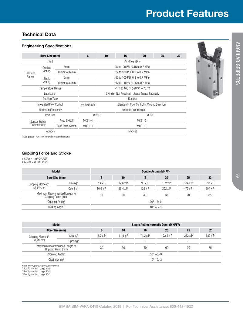
BIMBA BIM-VAPA-0419 Catalog 2019 | For Technical Assistance: 800-442-4622
99
Bore Size (mm) 6 10 16 20 25 32
Fluid Air (Clean/Dry)
Pressure Range
Double Acting
6mm 28 to 100 PSI (0.15 to 0.7 MPa)
10mm to 32mm 22 to 100 PSI (0.1 to 0.7 MPa)
Single Acting
6mm 50 to 100 PSI (0.3 to 0.7 MPa)
10mm to 32mm 36 to 100 PSI (0.25 to 0.7 MPa)
Temperature Range -4 ºF to 160 ºF (-20 ºC to 70 ºC)
Lubrication Cylinder: Not Required Jaws: Grease Regularly
Cushion Type Bumper
Integrated Flow Control Not Available Standard - Flow Control in Closing Direction
Maximum Frequency 180 cycles per minute
Port Size M3x0.5 M5x0.8
Sensor Switch Compatibility1
Reed Switch MCS1-H MCS1-G
Solid State Switch MDS1-H MDS1-G
Includes Magnet
Model Double Acting (MHFY)
Bore Size (mm) 6 10 16 20 25 32
Gripping Moment2,Mg (N-cm)
Closing3 7.4 x P 17.6 x P 90 x P 152 x P 304 x P 637 x P
Opening3 10.6 x P 29.4 x P 129 x P 252 x P 473 x P 904 x P
Maximum Recommended Length toGripping Point4 (mm) 30 30 40 60 70 85
Opening Angle3 30° +3/-0
Closing Angle3 10° +0/-3
Model Single Acting Normally Open (MHFTY)
Bore Size (mm) 6 10 16 20 25 32
Gripping Moment2,Mg (N-cm)
Closing3 5.7 x P 11.8 x P 71.2 x P 122.4 x P 252 x P 589 x P
Opening3 - - - - - -
Maximum Recommended Length toGripping Point4 (mm) 30 30 40 60 70 85
Opening Angle3 30° +3/-0
Closing Angle3 10° +0/-3
Note: P = Operating Pressure (MPa)² See figure 3 on page 102.³ See figure 4 on page 102.⁴ See figure 5 on page 102.
¹ See pages 104-107 for switch specifications
Technical Data
Engineering Specifications
1 MPa = 145.04 PSI1 N-cm = 0.089 lb-in
Gripping Force and Stroke
Product FeaturesAN
GULAR G
RIPPERS
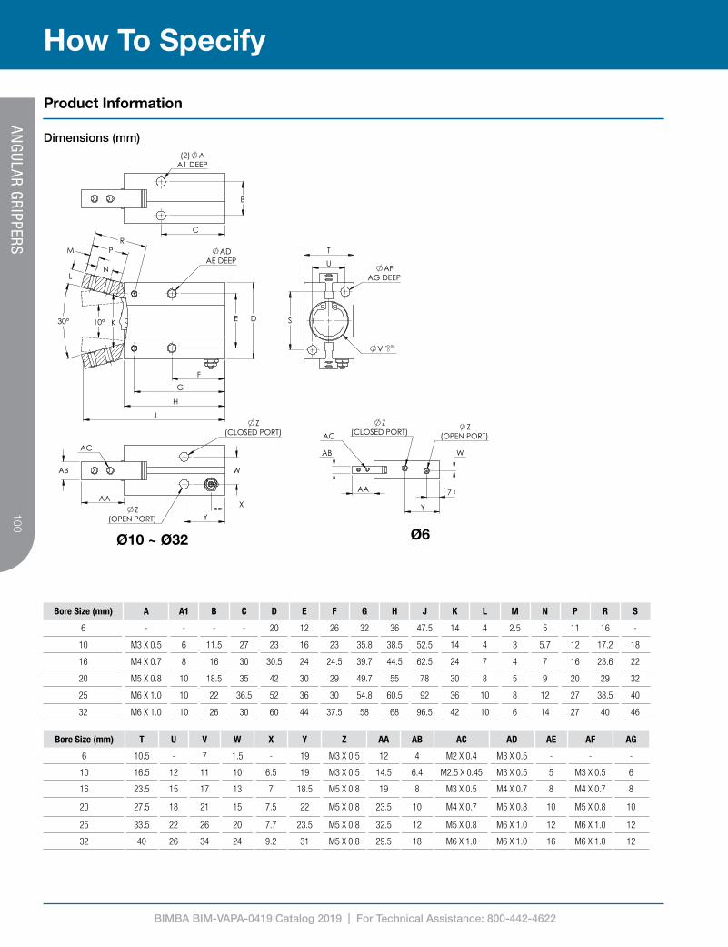
BIMBA BIM-VAPA-0419 Catalog 2019 | For Technical Assistance: 800-442-4622
100
How To Specify
Product Information
Dimensions (mm)
Bore Size (mm) A A1 B C D E F G H J K L M N P R S
6 - - - - 20 12 26 32 36 47.5 14 4 2.5 5 11 16 -
10 M3 X 0.5 6 11.5 27 23 16 23 35.8 38.5 52.5 14 4 3 5.7 12 17.2 18
16 M4 X 0.7 8 16 30 30.5 24 24.5 39.7 44.5 62.5 24 7 4 7 16 23.6 22
20 M5 X 0.8 10 18.5 35 42 30 29 49.7 55 78 30 8 5 9 20 29 32
25 M6 X 1.0 10 22 36.5 52 36 30 54.8 60.5 92 36 10 8 12 27 38.5 40
32 M6 X 1.0 10 26 30 60 44 37.5 58 68 96.5 42 10 6 14 27 40 46
Bore Size (mm) T U V W X Y Z AA AB AC AD AE AF AG
6 10.5 - 7 1.5 - 19 M3 X 0.5 12 4 M2 X 0.4 M3 X 0.5 - - -
10 16.5 12 11 10 6.5 19 M3 X 0.5 14.5 6.4 M2.5 X 0.45 M3 X 0.5 5 M3 X 0.5 6
16 23.5 15 17 13 7 18.5 M5 X 0.8 19 8 M3 X 0.5 M4 X 0.7 8 M4 X 0.7 8
20 27.5 18 21 15 7.5 22 M5 X 0.8 23.5 10 M4 X 0.7 M5 X 0.8 10 M5 X 0.8 10
25 33.5 22 26 20 7.7 23.5 M5 X 0.8 32.5 12 M5 X 0.8 M6 X 1.0 12 M6 X 1.0 12
32 40 26 34 24 9.2 31 M5 X 0.8 29.5 18 M6 X 1.0 M6 X 1.0 16 M6 X 1.0 12
Ø6Ø10 ~ Ø32
D E
F
G
H
30°
L
M
N
K
ADAE DEEP
J
P R
(2) AA1 DEEP
B
C
W
X
Y Z
(OPEN PORT)
AA
AB
Z(CLOSED PORT)
AC
T
U
S
V + 0.050
AFAG DEEP
10°
AB
AC
7
Y
W
Z(CLOSED PORT)
Z(OPEN PORT)
AA
ANG
ULAR GRIPPERS

BIMBA BIM-VAPA-0419 Catalog 2019 | For Technical Assistance: 800-442-4622
101
How To Order
How To Order
MHFY 20Bore Size
06 = 6mm
10 = 10mm
16 = 16mm
20 = 20mm
25 = 25mm
32 = 32mm
Model
MHFY = Double Acting
MHFTY = Single Acting, Normally Open
ANG
ULAR GRIPPERS

BIMBA BIM-VAPA-0419 Catalog 2019 | For Technical Assistance: 800-442-4622
102
Fg
Fg
Length to Gripping
Point
Closing Direction
Opening Direction
30° Opening
10° Closing
Length to Gripping
Point
Mg
Mg
How It Works
Technical Data
Figure 1Parallel GrippersGripping Force & Point
Figure 2Parallel GrippersGripping Direction
Closing Direction
Opening Direction
Figure 3Angular GrippersGripping Moment
Figure 4Angular GrippersOpening and Closing Angles
Figure 5Angular GrippersGripping Point
GRIPPER REFEREN
CE

BIMBA BIM-VAPA-0419 Catalog 2019 | For Technical Assistance: 800-442-4622
103
How To Specify
Product Information
Dimensions (mm)
Type Description Part Number Compatibility
Seal Kits
Extruded Thruster Seal Kits
Seal Kit, MTCL/MTCM 12mm Bore MTCK-12 12mm MTCL and MTCM Thrusters
Seal Kit, MTCL/MTCM 16mm Bore MTCK-16 16mm MTCL and MTCM Thrusters
Seal Kit, MTCL/MTCM 20mm Bore MTCK-20 20mm MTCL and MTCM Thrusters
Seal Kit, MTCL/MTCM 25mm Bore MTCK-25 25mm MTCL and MTCM Thrusters
Seal Kit, MTCL/MTCM 32mm Bore MTCK-32 32mm MTCL and MTCM Thrusters
Seal Kit, MTCL/MTCM 40mm Bore MTCK-40 40mm MTCL and MTCM Thrusters
Seal Kit, MTCL/MTCM 50mm Bore MTCK-50 50mm MTCL and MTCM Thrusters
Seal Kit, MTCL/MTCM 63mm Bore MTCK-63 63mm MTCL and MTCM Thrusters
High Temperature Seal Kit, MTCL/MTCM 12mm Bore MTCK-12V 12mm MTCL and MTCM Thrusters
High Temperature Seal Kit, MTCL/MTCM 16mm Bore MTCK-16V 16mm MTCL and MTCM Thrusters
High Temperature Seal Kit, MTCL/MTCM 20mm Bore MTCK-20V 20mm MTCL and MTCM Thrusters
High Temperature Seal Kit, MTCL/MTCM 25mm Bore MTCK-25V 25mm MTCL and MTCM Thrusters
High Temperature Seal Kit, MTCL/MTCM 32mm Bore MTCK-32V 32mm MTCL and MTCM Thrusters
High Temperature Seal Kit, MTCL/MTCM 40mm Bore MTCK-40V 40mm MTCL and MTCM Thrusters
High Temperature Seal Kit, MTCL/MTCM 50mm Bore MTCK-50V 50mm MTCL and MTCM Thrusters
High Temperature Seal Kit, MTCL/MTCM 63mm Bore MTCK-63V 63mm MTCL and MTCM Thrusters
Compact Cylinder Seal Kits
Seal Kit, MACQ 12mm Bore MACQK-12 12mm MACQ Cylinders
Seal Kit, MACQ 16mm Bore MACQK-16 16mm MACQ Cylinders
Seal Kit, MACQ 20mm Bore MACQK-20 20mm MACQ Cylinders
Seal Kit, MACQ 25mm Bore MACQK-25 25mm MACQ Cylinders
Seal Kit, MACQ 32mm Bore MACQK-32 32mm MACQ Cylinders
Seal Kit, MACQ 40mm Bore MACQK-40 40mm MACQ Cylinders
Seal Kit, MACQ 50mm Bore MACQK-50 50mm MACQ Cylinders
Seal Kit, MACQ 63mm Bore MACQK-63 63mm MACQ Cylinders
Seal Kit, MACQ 80mm Bore MACQK-80 80mm MACQ Cylinders
Seal Kit, MACQ 100mm Bore MACQK-100 100mm MACQ Cylinders
High Temperature Seal Kit, MACQ 12mm Bore MACQK-12V 12mm MACQ Cylinders
High Temperature Seal Kit, MACQ 16mm Bore MACQK-16V 16mm MACQ Cylinders
High Temperature Seal Kit, MACQ 20mm Bore MACQK-20V 20mm MACQ Cylinders
High Temperature Seal Kit, MACQ 25mm Bore MACQK-25V 25mm MACQ Cylinders
High Temperature Seal Kit, MACQ 32mm Bore MACQK-32V 32mm MACQ Cylinders
High Temperature Seal Kit, MACQ 40mm Bore MACQK-40V 40mm MACQ Cylinders
High Temperature Seal Kit, MACQ 50mm Bore MACQK-50V 50mm MACQ Cylinders
High Temperature Seal Kit, MACQ 63mm Bore MACQK-63V 63mm MACQ Cylinders
High Temperature Seal Kit, MACQ 80mm Bore MACQK-80V 80mm MACQ Cylinders
High Temperature Seal Kit, MACQ 100mm Bore MACQK-100V 100mm MACQ Cylinders
SERVICE PARTS

BIMBA BIM-VAPA-0419 Catalog 2019 | For Technical Assistance: 800-442-4622
104
Item/Type MCS1-G MDS1-GN MDS1-GP
Switch Logic SPST Normally Open Solid State Transistor, Normally Open
Sensor Type Reed Switch NPN PNP
Operating Voltage (V) 5-240V AC/DC 5-30V DC
Max. Switching Current (mA) 100 200
Max. Switching Power (W) 10 6
Current Consumption - 15mA Max. @ 24V
Voltage Drop 2.5V Max @ 100mA DC 0.5V Max. @ 200mA DC
Cable Ø2.8, 2C, Oil Resistant PVC (Flame Retardant) Ø3.3, 3C, Oil Resistant PVC
Indicator LED
Leakage Current - 0.01mA Max.
Sensitivity (Gauss) 60-75 60-75
Max. Frequency (Hz) 200 1000
Shock (m/s²) 300 500
Vibration (m/s²) 90
Temperature Range (°C) -10 to 70
Enclosure Classification IP67 (NEMA6)
Protection Circuit None Power Reverse Polarity, Surge Suppression
See page 107 for Switch Selector Guide
Product Features
Technical Data
Engineering Specifications
Dimensions (mm)
Wiring Diagrams
2 Wire Reed Switch 3 Wire Solid State NPN 3 Wire Solid State PNP
TRACK-MO
UNTED
SWITCH
- FOR SQ
UARE SWITCH
TRACKS

BIMBA BIM-VAPA-0419 Catalog 2019 | For Technical Assistance: 800-442-4622
105
How To Order
How To Order
¹ Available with MCS1 only² Available with MDS1 only
MDS1-GN-C08
Output
G = 2 Wire (Reed)1
GN = 3 Wire, NPN (Sinking)2
GP = 3 Wire, PNP (Sourcing)2
Wire Style
050 = Flying Leads, 5 Meter Wire Length
C08 = M8 Male Quick Connect, 150mm Wire Length
C12 = M12 Male Quick Connect, 150mm Wire Length
Model
MCS1 = Reed Switch
MDS1 = Solid State Switch
TRACK-MO
UNTED
SWITCH
- FOR SQ
UARE SWITCH
TRACKS

BIMBA BIM-VAPA-0419 Catalog 2019 | For Technical Assistance: 800-442-4622
106
Product Features
Item/Type MCS1-H MDS1-HN MDS1-HP
Switch Logic SPST Normally Open Solid State Transistor, Normally Open
Sensor Type Reed Switch NPN PNP
Operating Voltage (V) 5-120V AC/DC 5-30V DC
Max. Switching Current (mA) 50 200
Max. Switching Power (W) 6 6
Current Consumption - 15mA Max. @ 24V
Voltage Drop 3.0V Max 0.5V Max. @ 200mA DC
Cable Ø2.8, Polyurethane Ø3.3, 3C, Oil Resistant PVC
Indicator LED
Leakage Current - 0.01mA Max.
Sensitivity (Gauss) 40 60-75
Max. Frequency (Hz) 200 1000
Shock (m/s²) 300 500
Vibration (m/s²) 90
Temperature Range (°C) -10 to 70
Enclosure Classification IP67 (NEMA6)
Protection Circuit None Power Reverse Polarity, Surge Suppression
See page 107 for Switch Selector Guide.
Technical Data
Engineering Specifications
Dimensions (mm)
Wiring Diagrams
2 Wire Reed Switch3 Wire Solid State NPN 3 Wire Solid State PNP
¹ Available with MCS1 only² Available with MDS1 only
MDS1-HN-050
Output
H = 2 Wire (Reed)1
HN = 3 Wire, NPN (Sinking)2
HP = 3 Wire, PNP (Sourcing)2
Wire Style
010 = Flying Leads, 1 Meter Wire Length1
050 = Flying Leads, 5 Meter Wire Length2
Model
MCS1 = Reed Switch
MDS1 = Solid State Switch
How To OrderTRACK-M
OUN
TED SW
ITCH - FO
R 4MM
C-SLOTS
¹ Available with MCS1 only² Available with MDS1 only

BIMBA BIM-VAPA-0419 Catalog 2019 | For Technical Assistance: 800-442-4622
107
Reed Switch Solid State Switch
MCS1-G MCS1-H MDS1-G MDS1-H
MTC Thrusters All Bore Sizes X X
MACQ Compact Cylinders All Bore Sizes X X
MHRQ Rotary Actuators All Bore Sizes X X
MHFK Parallel Grippers
6mm Bore X X
10mm Bore X X
16-40mm Bore X X X X
MHFY Angular Grippers
6mm Bore X X
10-32mm Bore X X
How To Specify
Product Information
SWITCH
SELECTOR G
UIDE

Bimba 25150 S. Governors Hwy University Park, IL 60484
Tel: +1 708 534 8544 Fax: +1 708 235 2014
Due to our policy of continuous development, Bimba reserve the
right to change specifications without prior notice.
BIM-VAPA-0419
Selected Images used under license from Shutterstock.com
IMI Precision Engineering operates four global centres of technical excellence and a sales and service network in 75 countries, as well as manufacturing capability in
the USA, Germany, China, UK, Switzerland, Czech Republic,
Mexico and Brazil.
For information on all IMI Precision Engineering
companies visit www.imi-precision.com
Supported by distributors worldwide.
For further information, scan this QR code or visit www.bimba.com