industrial valves — actuators
TRANSCRIPT

BS EN15714-4:2009
ICS 23.060.20
NO COPYING WITHOUT BSI PERMISSION EXCEPT AS PERMITTED BY COPYRIGHT LAW
BRITISH STANDARD
Industrial valves —ActuatorsPart 4: Hydraulic part-turn actuatorsfor industrial valves — Basicrequirements

This British Standardwas published underthe authority of theStandards Policy andStrategy Committee on 30November 2009© BSI 2009
ISBN 978 0 580 54844 4
Amendments/corrigenda issued since publication
Date Comments
BS EN 15714-4:2009
National foreword
This British Standard is the UK implementation of EN 15714-4:2009.The UK participation in its preparation was entrusted to TechnicalCommittee PSE/18/5, Valve actuators.A list of organizations represented on this committee can be obtained onrequest to its secretary.This publication does not purport to include all the necessary provisionsof a contract. Users are responsible for its correct application.Compliance with a British Standard cannot confer immunityfrom legal obligations.
标准分享网 www.bzfxw.com 免费下载

www.bzfxw.com
BS EN 15714-4:2009
EUROPEAN STANDARD
NORME EUROPÉENNE
EUROPÄISCHE NORM
EN 15714-4
October 2009
ICS 23.060.20
English Version
Industrial valves - Actuators - Part 4: Hydraulic part-turn actuators for industrial valves - Basic requirements
Robinetterie industrielle - Actionneurs - Partie 4: Actionneurs hydrauliques à fraction de tour pour robinetterie industrielle - Prescriptions de base
Industriearmaturen - Antriebe - Teil 4: Hydraulische Schwenkantriebe für Industriearmaturen -
Grundanforderungen
This European Standard was approved by CEN on 12 September 2009. CEN members are bound to comply with the CEN/CENELEC Internal Regulations which stipulate the conditions for giving this European Standard the status of a national standard without any alteration. Up-to-date lists and bibliographical references concerning such national standards may be obtained on application to the CEN Management Centre or to any CEN member. This European Standard exists in three official versions (English, French, German). A version in any other language made by translation under the respons bility of a CEN member into its own language and notified to the CEN Management Centre has the same status as the official versions. CEN members are the national standards bodies of Austria, Belgium, Bulgaria, Cyprus, Czech Republic, Denmark, Estonia, Finland, France, Germany, Greece, Hungary, Iceland, Ireland, Italy, Latvia, Lithuania, Luxembourg, Malta, Netherlands, Norway, Poland, Portugal, Romania, Slovakia, Slovenia, Spain, Sweden, Switzerland and United Kingdom.
EUROPEAN COMMITTEE FOR STANDARDIZATION C O M I T É E U R O P É E N D E N O R M A LI S A T I O N EUR OP ÄIS C HES KOM ITEE FÜR NOR M UNG
Management Centre: Avenue Marnix 17, B-1000 Brussels
© 2009 CEN All rights of exploitation in any form and by any means reserved worldwide for CEN national Members.
Ref. No. EN 15714-4:2009: E

www.bzfxw.com
BS EN 15714-4:2009EN 15714-4:2009 (E)
2
Contents Page
Foreword ..............................................................................................................................................................4
1 Scope ......................................................................................................................................................5
2 Normative references ............................................................................................................................5
3 Classification and designation .............................................................................................................53.1 General ....................................................................................................................................................53.2 Action ......................................................................................................................................................63.3 Valve actuator attachment ....................................................................................................................63.4 Motive energy .........................................................................................................................................63.4.1 Operating medium .................................................................................................................................63.4.2 Quality .....................................................................................................................................................63.4.3 Pressure ..................................................................................................................................................6
4 Design requirements .............................................................................................................................64.1 General ....................................................................................................................................................64.2 Output torques (performance test) ......................................................................................................74.3 Pressure ratings and endurance ..........................................................................................................74.3.1 Pressure ratings.....................................................................................................................................74.3.2 Endurance ..............................................................................................................................................74.4 Minimum moving pressure ...................................................................................................................84.5 Leakage ...................................................................................................................................................84.6 Moving time ............................................................................................................................................84.7 Angle .......................................................................................................................................................94.8 Fluid displacement volume ...................................................................................................................94.9 Environmental conditions .....................................................................................................................94.9.1 Ambient temperature .............................................................................................................................94.9.2 Enclosure protection .............................................................................................................................94.9.3 Corrosion protection .............................................................................................................................94.10 Basic design ........................................................................................................................................ 104.10.1 Safety requirements ........................................................................................................................... 104.10.2 Part-turn valve actuator attachment ................................................................................................. 104.10.3 Pressure connections ........................................................................................................................ 114.10.4 Fail safe direction for spring return actuators ................................................................................. 124.10.5 Mechanical safety factors .................................................................................................................. 124.11 Position indication .............................................................................................................................. 124.12 Optional equipment ............................................................................................................................ 134.12.1 Ancillaries ............................................................................................................................................ 134.12.2 Manual operation ................................................................................................................................ 154.12.3 End stop adjustment .......................................................................................................................... 15
5 Conformity assessment ..................................................................................................................... 155.1 General ................................................................................................................................................. 155.2 Type tests ............................................................................................................................................ 165.3 Control of production process and quality system ........................................................................ 16
6 Marking ................................................................................................................................................ 17
7 Actuator selection guidelines ............................................................................................................ 18
8 Documentation .................................................................................................................................... 18
Annex A (normative) Endurance test procedure .......................................................................................... 19A.1 General ................................................................................................................................................. 19A.2 Test equipment ................................................................................................................................... 19
标准分享网 www.bzfxw.com 免费下载

www.bzfxw.com
BS EN 15714-4:2009EN 15714-4:2009 (E)
3
A.3 Test conditions .................................................................................................................................... 19A.4 Test procedure ..................................................................................................................................... 19A.4.1 Design life............................................................................................................................................. 19A.4.2 Output torque testing .......................................................................................................................... 19A.4.3 Pressure testing .................................................................................................................................. 19A.4.4 Hydraulic testing ................................................................................................................................. 20A.5 Acceptance criteria ............................................................................................................................. 20
Annex B (informative) Actuator selection guidelines ................................................................................... 21B.1 General ................................................................................................................................................. 21B.2 Selection parameters .......................................................................................................................... 21B.3 Actuator selection ............................................................................................................................... 22B.3.1 General ................................................................................................................................................. 22B.3.2 Torque characteristics for rack and pinion or linear helical spline actuators .............................. 23B.3.3 Torque characteristics for scotch yoke actuators (e.g. symmetric system) ................................. 24
Bibliography ...................................................................................................................................................... 25

www.bzfxw.com
BS EN 15714-4:2009EN 15714-4:2009 (E)
4
Foreword
This document (EN 15714-4:2009) has been prepared by Technical Committee CEN/TC 69 “Industrial valves”, the secretariat of which is held by AFNOR.
This European Standard shall be given the status of a national standard, either by publication of an identical text or by endorsement, at the latest by April 2010, and conflicting national standards shall be withdrawn at the latest by April 2010.
Attention is drawn to the possibility that some of the elements of this document may be the subject of patent rights. CEN [and/or CENELEC] shall not be held responsible for identifying any or all such patent rights.
According to the CEN/CENELEC Internal Regulations, the national standards organizations of the following countries are bound to implement this European Standard: Austria, Belgium, Bulgaria, Cyprus, Czech Republic, Denmark, Estonia, Finland, France, Germany, Greece, Hungary, Iceland, Ireland, Italy, Latvia, Lithuania, Luxembourg, Malta, Netherlands, Norway, Poland, Portugal, Romania, Slovakia, Slovenia, Spain, Sweden, Switzerland and United Kingdom.
标准分享网 www.bzfxw.com 免费下载

www.bzfxw.com
BS EN 15714-4:2009EN 15714-4:2009 (E)
5
1 Scope
This document provides basic requirements for hydraulic part-turn valve actuators, both double acting and single acting, used for on-off and modulating control duties. It includes guidelines, recommendations and methods for enclosure and corrosion protection, control and testing.
It does not apply, to hydraulic actuators that are integral parts of control valves or to electro-hydraulic actuators.
Other requirements or conditions of use different from those indicated in this document should be subject to negotiations between the purchaser and the manufacturer/supplier prior to order.
The terms and definitions applicable to this European Standard are given in EN 15714-1.
2 Normative references
The following referenced documents are indispensable for the application of this document. For dated references, only the edition cited applies. For undated references, the latest edition of the referenced document (including any amendments) applies.
EN 12570, Industrial valves — Method for sizing the operating element
EN 60529, Degrees of protection provided by enclosures (IP Code) (IEC 60529:1989)
EN ISO 228-1, Pipe threads where pressure-tight joints are not made on the threads — Part 1: Dimensions, tolerances and designation (ISO 228-1:2000)
EN ISO 5211, Industrial valves — Part-turn valve actuator attachments (ISO 5211:2001)
EN ISO 9227, Corrosion tests in artificial atmospheres — Salt spray tests (ISO 9227:2006)
ISO 4406, Hydraulic fluid power — Fluids — Method for coding the level of contamination by solid particles
ISO 5599-2, Pneumatic fluid power — Five-port directional control valves — Part 2: Mounting interface surfaces with optional electrical connector
ASME B1.20.1:1983, Pipe Threads, General Purpose (Inch)
3 Classification and designation
3.1 General
Hydraulic part-turn actuators are designated by function, action and interface as detailed below.

www.bzfxw.com
BS EN 15714-4:2009EN 15714-4:2009 (E)
6
3.2 Action
a) Double Acting (DA)
b) Single Acting (SA) with spring action to move clock-wise (CW) or counter clock-wise (CCW), as per 4.10.4
3.3 Valve actuator attachment
As per EN ISO 5211.
3.4 Motive energy
3.4.1 Operating medium
The operating medium shall be hydraulic fluid.
The fluid may be used, on agreement between the manufacturer/supplier and purchaser, ensuring it is designed for both pressure and compatible with internal actuator parts and lubricants.
The flashpoint shall be of not less than 93 °C for pressures below 1 MPa and 157 °C for pressures above 1 MPa.
The chemical and physical properties of the hydraulic fluid shall be suitable for use with the materials used in the design of the actuator and its accessories.
The hydraulic fluid shall be suitable for operation of the hydraulic system through the entire temperature range to which it may be subjected in service.
3.4.2 Quality
The operating medium shall have a contamination level specified to ISO 4406 class 18/16/13 as a maximum.
3.4.3 Pressure
The manufacturer/supplier shall indicate the actuator’s operating pressure limits.
The minimum design pressure for pressure retaining parts shall be 1,1 times the maximum allowable pressure selected from the values defined in 4.3.1. The test pressure condition shall be considered in the design of the actuator for pressure containing parts, see 4.10.5.
Working pressure in accordance to manufacturer/supplier indication (as per 4.3.1).
The test pressure applied to the pressure retaining parts shall be a minimum of 1,43 times the design pressure for steel enclosures and a minimum of twice the maximum working pressure for cast steel and spheroidal cast iron enclosures
Hydrostatic testing shall be carried out at testing pressure.
4 Design requirements
4.1 General
The following data shall be provided by the manufacturer/supplier to enable correct actuator selection and performance evaluation.
标准分享网 www.bzfxw.com 免费下载

www.bzfxw.com
BS EN 15714-4:2009EN 15714-4:2009 (E)
7
4.2 Output torques (performance test)
The guaranteed minimum, output torque capability of the actuator, in both directions, at specified operating pressures shall be provided by the manufacturer/supplier.
Where the output torque varies with the rotation, in a non-linear relationship, tabulated data and/or torque curves shall be provided.
4.3 Pressure ratings and endurance
4.3.1 Pressure ratings
Actuators shall be designed to operate with one of the following maximum allowable pressures.
Table 1 — Maximum allowable pressure
Maximum allowable pressure
MPa bar psi
5,5 55 800
10,3 103 1 500
20,7 207 3 000
34,5 345 5 000
4.3.2 Endurance
The actuator shall be designed to have a minimum endurance, without maintenance, in accordance with values given in Table 2. These are based of at least 60 % of the run torque at a rated working pressure supplied by the operating medium defined in 3.4.1 (Motive Energy) and in accordance with the test procedure detailed in Annex A.

www.bzfxw.com
BS EN 15714-4:2009EN 15714-4:2009 (E)
8
Table 2 — Minimum number of cycles — Endurance test
Rated torque a
Nm
Piston or vane actuator Minimum number of cycles b c
Maximum stroking time for testing, based on 0-90°
s
≤ 125 50 000 10
≤ 1 000 50 000 20
≤ 2 000 25 000 30
≤ 8 000 10 000 45
≤ 32 000 2 500 60
≤ 63 000 2 500 90
≤ 125 000 2 500 120
≤ 250 000 2 500 150 a Based on EN ISO 5211. b One cycle consists of nominal 90° angular travel in both directions (i.e. 90° to open + 90° to close).
For angular travel other than 90°, the endurance shall be agreed between the purchaser and the manufacturer/supplier. c For severe control service duty these values shall be agreed between manufacturer/supplier and purchaser.
4.4 Minimum moving pressure
The actuator minimum moving pressure, at ambient temperature, shall be made available, by the manufacturer/supplier upon request.
4.5 Leakage
The actuator shall be pressure tested in two stages by applying pressures of 15 to 25 % and a minimum of 143 % of the maximum allowable pressure of the actuator.
The actuator shall have no visible external leakage as detailed in Table 8 for the duration of the production test.
The test media shall be specified by the manufacturer.
The test media always shall be compatible with the operation media of the supplied actuator.
The minimum test duration for each test pressure shall be 3 minutes. The test period shall not begin until the test pressure has been reached and has stabilised. The tests gauge pressure reading and time at the beginning and the end of each pressure holding period shall be recorded.
4.6 Moving time
The actuator manufacturer/supplier shall state the moving time in both directions, without external load and without valve at working pressure and without any significant external restriction on supply flow, unless otherwise specified.
标准分享网 www.bzfxw.com 免费下载

www.bzfxw.com
BS EN 15714-4:2009EN 15714-4:2009 (E)
9
4.7 Angle
Part-turn actuators without adjustable end-stops shall be designed for an output movement of 90° (- 0°, + 2°) as standard.
For part-turn actuators with adjustable end-stops and a standard nominal output movement of 90°, the adjustment range shall be stated by the manufacturer/supplier and shall be, at least, ± 3°.
Other angles are subject to agreement between the manufacturer/supplier and purchaser.
4.8 Fluid displacement volume
The manufacturer/supplier shall indicate the internal actuator displaced volume (litres) for both directions, including the dead volumes.
4.9 Environmental conditions
4.9.1 Ambient temperature
The actuator shall be designed for operation at an ambient temperature range between – 20 °C and + 60 °C, unless otherwise agreed between the manufacturer/supplier and purchaser.
4.9.2 Enclosure protection
The non pressurised enclosure of the actuator shall be at least IP 65, according to EN 60529.
4.9.3 Corrosion protection
Hydraulic actuators shall be protected against external corrosion by proper material selection and/or surface treatment. The actuator manufacturer's technical documentation shall specify the corrosion protection category according to Table 3.

www.bzfxw.com
BS EN 15714-4:2009EN 15714-4:2009 (E)
10
Table 3 — Environmental corrosion categories
Corrosion category Typical environments
Exterior Interior
C2 (low) Atmospheres with low level of pollution. Mostly rural areas.
Unheated buildings where condensation may occur, e.g. depots, sport halls.
C3 (medium) Urban and industrial atmospheres, moderate sulphur dioxide pollution. Coastal areas with low salinity.
Production rooms with high humidity and some air pollution, e.g. food-processing plants, laundries, breweries.
C4 (high) Industrial areas and coastal areas with moderate salinity.
Chemical plants, swimming pools, coastal shipyards.
C5-I (very high — industrial) Industrial areas with high humidity and aggressive atmosphere.
Buildings or areas with almost permanent condensation and with high pollution.
C5-M (very high — marine) Coastal and offshore areas with high salinity.
Buildings or areas with almost permanent condensation and with high pollution.
Immersed in water a
Im 1 (Immersed in fresh water)
River installations, hydro-electric power plants.
Im 2 (Immersed in sea or brackish water)
Harbour areas and offshore structures.
a Hydraulic actuators covered by this European Standard are not designed for permanent immersion unless otherwise specified.
NOTE 1 Table 3 is taken, for reference purposes only, from EN ISO 12944-2. The actuator corrosion protection may also be achieved by systems/methods which deviate from those specified in EN ISO 12944-5.
NOTE 2 Table 3 may be used to define the corrosion category in order to help the actuator manufacturers to define the surface treatment for corrosion protection. Test assessment and test procedures are the responsibility of the manufacturer.
4.10 Basic design
4.10.1 Safety requirements
Actuators shall be designed taking into account the technical principles and specifications for safety. The design of spring return actuators shall permit the safe assembly/disassembly, when complying with the manufacturer/supplier’s instructions.
4.10.2 Part-turn valve actuator attachment
The valve attachment for part-turn actuators shall comply with EN ISO 5211.
The output drive of part-turn actuators may be an integral part or a removable component.
The material of the drive component shall be clearly indicated in the supplier’s literature.
标准分享网 www.bzfxw.com 免费下载
www.bzfxw.com
BS EN 15714-4:2009EN 15714-4:2009 (E)
11
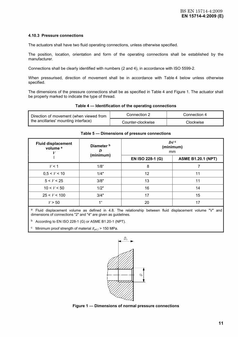
4.10.3 Pressure connections
The actuators shall have two fluid operating connections, unless otherwise specified.
The position, location, orientation and form of the operating connections shall be established by the manufacturer.
Connections shall be clearly identified with numbers (2 and 4), in accordance with ISO 5599-2.
When pressurised, direction of movement shall be in accordance with Table 4 below unless otherwise specified.
The dimensions of the pressure connections shall be as specified in Table 4 and Figure 1. The actuator shall be properly marked to indicate the type of thread.
Table 4 — Identification of the operating connections
Direction of movement (when viewed from the ancillaries' mounting interface)
Connection 2 Connection 4
Counter-clockwise Clockwise
Table 5 — Dimensions of pressure connections
Fluid displacement volume a
V l
Diameter b D
(minimum)
D4 c (minimum)
mm
EN ISO 228-1 (G) ASME B1.20.1 (NPT)
V < 1 1/8“ 8 7
0,5 < V < 10 1/4" 12 11
5 < V < 25 3/8" 13 11
10 < V < 50 1/2" 16 14
25 < V < 100 3/4" 17 15
V > 50 1“ 20 17 a Fluid displacement volume as defined in 4.8. The relationship between fluid displacement volume "V" and dimensions of connections "2" and "4" are given as guidelines. b According to EN ISO 228-1 (G) or ASME B1.20-1 (NPT). c Minimum proof strength of material Rp0,2 > 150 MPa.
Figure 1 — Dimensions of normal pressure connections

www.bzfxw.com
BS EN 15714-4:2009EN 15714-4:2009 (E)
12
Test and gage connection ports shall be internally threaded and provide a leak tight seal at the hydraulic test pressure.
All connections shall provide a leak tight seal at the hydraulic test pressure of the equipment in which they are installed.
4.10.4 Fail safe direction for spring return actuators
For spring return actuators, the direction of movement, on loss of operating pressure shall be clearly and permanently indicated in accordance with Figure 2 (See Clause 6).
a) Turn clockwise (CW) b) Turn counter clockwise (CCW)
Figure 2 — Fail safe directions for part-turn actuators
4.10.5 Mechanical safety factors
Pressurised actuator enclosures shall be designed with minimum safety factors as given in Table 6 below.
Table 6 — Minimum safety factors
Material Yield strength 0,2 %
or 1,0 % proof strength as appropriate
Tensile strength
Ferritic steel Rp0,2/1,5 Rm/2,4
Austenitic stainless steel, A5 >30 % Rp1,0/1,5 —
Austenitic stainless steel, A5 > 35 % Rp1,0/1,2 Rm/3
Cast steel and spheroidal graphite cast iron Rp0,2/1,9 Rm/3
Aluminium Rp0,2/1,5 —
Aluminium (non hardenable) Rp0,2/1,5 Rm/2,4
Other materials Calculations shall utilise the values appropriate to the properties of the material.
Unpressurised enclosures shall be designed to remain unpressurised also in case of mulfunction or failure.
4.11 Position indication
The actuator shall be equipped with an indicating arrangement or device to clearly show the valve obturator’s position, which shall be linked with the valve obturator during power and/or manual operation. It shall be possible to adjust the indicator when necessary.
标准分享网 www.bzfxw.com 免费下载

www.bzfxw.com
BS EN 15714-4:2009EN 15714-4:2009 (E)
13
4.12 Optional equipment
4.12.1 Ancillaries
The actuator design shall allow the attachment of ancillaries, such as:
a) limit switches;
b) proportional valve;
c) position transmitter;
d) solenoid and/or manual operated valves;
e) adjustable flow control devices;
f) safety devices.
The actuator shall have an ancillaries’ mounting interface as shown in Table 7 or as agreed between the manufacturer/supplier and the purchaser.
The actuator interface shall have 4 threaded holes according to Table 7 and Figure 3 (see also EN 60534-6-2).
The length C of the drive shaft, distances A and B of the holes and relevant attachment dimensions, for mounting level 1, shall be in accordance with Table 7.
The shaft shall have a slot and a threaded hole according to Figure 3. If the slot is used as a position indicator it shall be parallel to the pipe axis when the valve is open.

www.bzfxw.com
BS EN 15714-4:2009EN 15714-4:2009 (E)
14
Key 1 mounting level
Figure 3 — Dimensions of accessories flange for part turn actuators
Table 7 — Dimensions of the actuator interface for the attachments of ancillaries for mounting level 1
Size Fluid displacement volume a
V l
A B C D E (minimum)
H
AA 0 V < 1 50 25 15 M5 8 40
AA 1 0,5 < V < 10 80 30 20 M5 8 45
AA 2 5< V < 25 80 30 30 M5 8 55
AA 3 5 < V < 25 130 30 30 M5 8 55
AA 4 10 < V < 100 130 30 50 M5 8 75
AA 5 V > 50 200 50 80 M6 10 105 a Fluid displacement volume as defined in 4.8. The relationship between fluid displacement volume V and dimensions of mounting levels 1 and 2 are given as guidelines.
The mounting of positioners and signal devices to part-turn actuators is also possible with a bracket with dimensions according to the Table 7 and Figure 4.
标准分享网 www.bzfxw.com 免费下载

www.bzfxw.com
BS EN 15714-4:2009EN 15714-4:2009 (E)
15
Mounting Level 1: fixing level for the bracket to an actuator with dimensions given in Table 7.
Mounting Level 2: fixing level on the bracket for positioners and signal devices with F05 attachment in accordance with EN ISO 5211.
Key 1 mounting level 2; positioner / signal device 2 mounting level 1; actuator a 5,5 (for M5) or 6,5 (for M6)
Figure 4 — Dimensions of optional ancillaries bracket
4.12.2 Manual operation
When specified, the actuator shall be supplied with a means of manual operation.
The manual operating forces shall be in accordance with EN 12570.
The design shall include the following safety related features.
a) The manual operating element (hand-wheel, lever or hydraulic device) shall remain stationary under power operation.
b) The power operation shall be disabled before or when manual operation is engaged.
c) Clear and permanent indication shall be provided to show the opening/closing directions of the manual override which shall be clockwise (CW) to close (hand-wheel or handle), unless otherwise specified.
4.12.3 End stop adjustment
When required, part-turn actuators shall be supplied with at least one adjustable end-stop (refer to 4.7).
5 Conformity assessment
5.1 General
The manufacturer/supplier shall demonstrate the compliance of his products to this European Standard by:

www.bzfxw.com
BS EN 15714-4:2009EN 15714-4:2009 (E)
16
a) carrying out all the type tests (see 5.2) to ensure all “fitness for purpose” criteria are met;
b) controlling the production process (see 5.3) to ensure the required performance levels are continuously maintained.
5.2 Type tests
The type tests shall correspond to all requirements stated in Clause 4.
Type test shall be carried out on actuators that are representative of the current production.
Type tests results shall be recorded in a test report, detailing the type, quantity and sizes of the actuators tested and the test equipment and measuring devices used.
To qualify a range of actuators, of the same design, manufactured under the same process and from the same or equivalent materials, the type tests may be carried out on a limited number of sizes by applying the following rule:
When an actuator having a nominal output torque “x” is qualified, all actuators having nominal output torque's between 50 % x and 200 % x [x/2 or 2x] are considered qualified.
When an actuator with a rotation of “y” is qualified, all actuators having a rotation between “y/2” and “2y” are also considered qualified.
The type test shall be carried out by the manufacturer/suppliers, or by a competent testing institute.
A full report of these tests shall be retained by the manufacturer/supplier as evidence of compliance.
The appropriate type tests shall be repeated when the design or the production processes have been modified, which could affect the functional performances.
The type tests to be performed shall be those given in Table 8.
5.3 Control of production process and quality system
The manufacturer/supplier shall have a Quality Control System capable of ensuring manufactured products comply with the performance requirements of this European Standard.
The production verifications to be performed should be those given in Table 8.
标准分享网 www.bzfxw.com 免费下载
www.bzfxw.com
BS EN 15714-4:2009EN 15714-4:2009 (E)
17
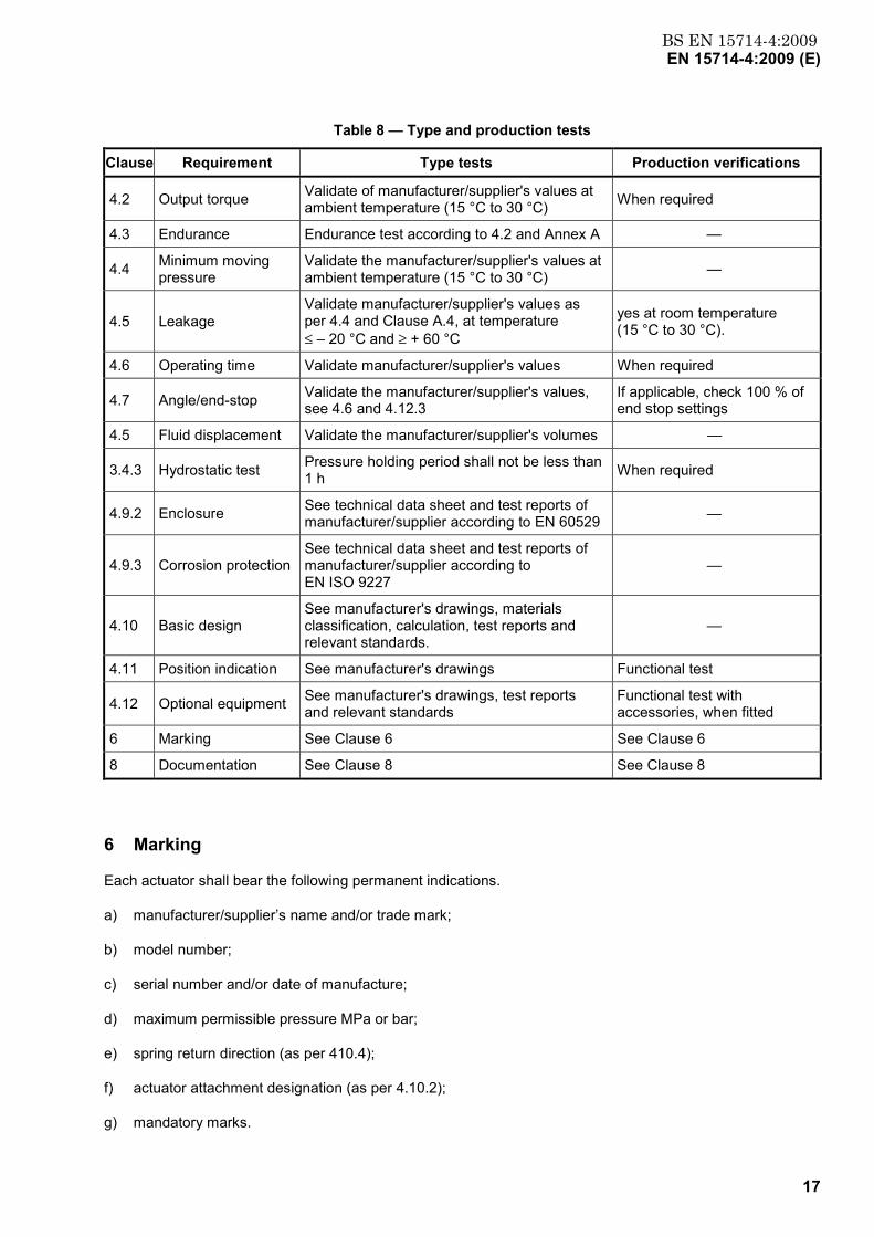
Table 8 — Type and production tests
Clause Requirement Type tests Production verifications
4.2 Output torque Validate of manufacturer/supplier's values at ambient temperature (15 °C to 30 °C) When required
4.3 Endurance Endurance test according to 4.2 and Annex A —
4.4 Minimum moving pressure
Validate the manufacturer/supplier's values at ambient temperature (15 °C to 30 °C) —
4.5 Leakage Validate manufacturer/supplier's values as per 4.4 and Clause A.4, at temperature ≤ – 20 °C and ≥ + 60 °C
yes at room temperature (15 °C to 30 °C).
4.6 Operating time Validate manufacturer/supplier's values When required
4.7 Angle/end-stop Validate the manufacturer/supplier's values, see 4.6 and 4.12.3
If applicable, check 100 % of end stop settings
4.5 Fluid displacement Validate the manufacturer/supplier's volumes —
3.4.3 Hydrostatic test Pressure holding period shall not be less than 1 h When required
4.9.2 Enclosure See technical data sheet and test reports of manufacturer/supplier according to EN 60529 —
4.9.3 Corrosion protection See technical data sheet and test reports of manufacturer/supplier according to EN ISO 9227
—
4.10 Basic design See manufacturer's drawings, materials classification, calculation, test reports and relevant standards.
—
4.11 Position indication See manufacturer's drawings Functional test
4.12 Optional equipment See manufacturer's drawings, test reports and relevant standards
Functional test with accessories, when fitted
6 Marking See Clause 6 See Clause 6
8 Documentation See Clause 8 See Clause 8
6 Marking
Each actuator shall bear the following permanent indications.
a) manufacturer/supplier’s name and/or trade mark;
b) model number;
c) serial number and/or date of manufacture;
d) maximum permissible pressure MPa or bar;
e) spring return direction (as per 410.4);
f) actuator attachment designation (as per 4.10.2);
g) mandatory marks.

www.bzfxw.com
BS EN 15714-4:2009EN 15714-4:2009 (E)
18
The following information is optional:
h) reference to this European Standard;
i) nominal operating connection types (as per 4.10.3);
j) connection types (as per 4.10.3);
k) ancillary attachment type (as per 4.12.1);
l) maximum output torque;
m) nominal output torque.
7 Actuator selection guidelines
Annex B gives detailed explanations for a proper actuator selection.
8 Documentation
The language of the relevant documentation shall be agreed between the manufacturer/supplier and the purchaser.
The manufacturer/supplier shall provide the following:
a) transport and storage instructions;
b) pressure connection type (as per Table 5);
c) installation, commissioning, operating and maintenance instructions;
d) mandatory documentation.
The following is optional:
e) detailed overhaul instructions;
f) hydraulic schematic and electric wiring diagram (when applicable);
g) itemized spare parts list;
h) list of recommended spare parts;
i) production test certificate (as per 5.3).
标准分享网 www.bzfxw.com 免费下载

www.bzfxw.com
BS EN 15714-4:2009EN 15714-4:2009 (E)
19
Annex A (normative)
Endurance test procedure
A.1 General
Actuators complying with this European Standard shall be type-tested in agreement with the following.
A.2 Test equipment
The test rig shall provide a measurable torque, shall allow the fixing of the actuator and shall be suitably designed to allow the full travel of the actuator.
The test rig shall be equipped with the following calibrated devices:
a) a leakage measurement device;
b) a pressure measurement device;
c) an operating cycle counter;
d) an instrument for measuring the applied torque and the operating stroke;
e) an angular position measuring device.
A.3 Test conditions
The test shall be conducted at ambient temperature (between 15 °C and 30 °C), under the conditions given in 4.3. The motive energy shall be hydraulic fluid and shall comply with 4.9.
A.4 Test procedure
A.4.1 Design life
The operating time and cycles shall be as specified by the manufacturer, in accordance with 4.3.2.
A.4.2 Output torque testing
Torque values versus angular stroke, in 10° intervals in both directions of travel, shall be recorded, at least at the start and at the end of the endurance test.
A.4.3 Pressure testing
Actuator leakage rates at test temperatures, ≤ - 20 °C and ≥ + 60 °C, shall be measured and recorded at the beginning and at the end of the test, at both end positions. Values should be based on NTP (Normal Temperature & Pressure).

www.bzfxw.com
BS EN 15714-4:2009EN 15714-4:2009 (E)
20
A.4.4 Hydraulic testing
The test period shall not begin until the test pressure has been reached and has stabilised and the equipment and the pressure-monitoring device have been isolated from the pressure source.
Water with or without additives or hydraulic fluid may be used as testing fluid.
A.5 Acceptance criteria
At the end of the test, results shall comply with the following criteria.
a) Output torque testing.
b) The final torque values shall not be less than 90 % of the initial values.
c) The final leakage values.
d) The equipment shall show no visible leakage during the holding period.
标准分享网 www.bzfxw.com 免费下载

www.bzfxw.com
BS EN 15714-4:2009EN 15714-4:2009 (E)
21
Annex B (informative)
Actuator selection guidelines
B.1 General
Actuated valve malfunctions are often due to the under sizing of actuators. The initial material cost «saving» is usually insignificant, compared with the costly production losses and/or danger presented to personnel.
Conversely, it is even more important, that excessive safety factors are not applied to valve torques which may result in selected actuators being capable of twisting/shearing valve stems and possibly transmitting a feedback signal that does not correspond to the valve position. This is usually associated with critical valve applications e.g. ESD (Emergency Shut Down) valves.
It is therefore essential that the correct size of actuator is selected together with any associated ancillary equipment.
To obtain all the information it may be necessary to question the end user, the contractor/designer, the valve manufacturer, the actuator manufacturer and ancillary equipment manufacturers.
The aim of these guidelines is to provide a clear understanding of the torque requirements and what parameters affect the correct actuator selection. Relevant questions need to be answered regarding the valve operating service, the actuator working parameters/environment, ancillary equipment and local regulations.
B.2 Selection parameters
Determine the appropriate torques and strokes taking into consideration the following parameters and questions
1.0 Valve Questions:
1.1. Valve manufacturer, type, size, function and operating characteristics.
1.2. Operating conditions: media, temperature, pressure, flow rate, frequency of operation and required stroking time.
1.3. Valve torque characteristics [seating/unseating, dynamic torque (when applicable)].
1.4. Maximum allowable stem torque limitation (MAST).1
1.5. Safety factors.
2.0 Actuator Questions:
2.1. Motive energy.
2.2. Supply pressure: minimum and maximum.
2.3. Duty: on/off or control.
2.4. Action: double acting or single acting, (spring to open or spring to close).
2.5. Fail-safe requirement: to open, close or stay put, also considering associated pilot valves.
1 Note that the valve stem is not necessarily the weakest part in the drive train.

www.bzfxw.com
BS EN 15714-4:2009EN 15714-4:2009 (E)
22
2.6. Moving time in both directions.
2.7. Frequency of operations.
3.0 Ancillary questions:
3.1. Limit switches: type, voltage and local electrical regulations.
3.2. Positioners: hydraulic or electro-hydraulic.
3.3. Position transmitters: local electrical regulations.
3.4. Solenoid valve: consider all actuator questions (adjustable flow control devices may be required when considering 2.6).
4.0 Environmental conditions:
4.1. Indoor, outdoor, saline, corrosive chemicals, etc..
4.2. Enclosure protection type.
4.3. Hazardous or non-hazardous areas.
4.4. Ambient temperature.
NOTE These points are relevant to all ancillaries and suitable materials/protection should be selected.
B.3 Actuator selection
B.3.1 General
After providing answers to clause 1.0, it is the responsibility of the valve manufacturer to provide operating torque values, throughout the valve’s stroke in both directions, including any relevant safety factors and the maximum torque that can be applied to the valve stem.
Once the valve’s torque characteristic values have been established, select an actuator, considering the minimum supply pressure specified by the purchaser, that provides a torque (Start torque, Run torque (when applicable) and End torque) greater than the maximum valve operating torque, taking into consideration varying valve torque values throughout its stroke, in both directions.
The Figures B2-1, B2-2, B2-3 and B2-4 give, as examples, the torque characteristics (force and vector) of the mainly used mechanical systems (rack and pinion, linear helical spline and scotch yoke actuators).
At the maximum supply pressure, the maximum output torque of the selected actuator shall not exceed the maximum allowable valve stem torque limitation (MAST).
Moving time is checked and if necessary, modifications and/or the appropriate ancillary equipment is selected.
Select appropriate materials, corrosion protection system, command and control ancillaries according to the environmental conditions, local regulations and purchaser requirements/specifications.
标准分享网 www.bzfxw.com 免费下载

www.bzfxw.com
BS EN 15714-4:2009EN 15714-4:2009 (E)
23
B.3.2 Torque characteristics for rack and pinion or linear helical spline actuators
Key X travel (degrees) Y output a closed b open c start Opening, End Closing d end Opening, Start Closing
Figure B.1 — Double acting actuator
a) Fail save close b) Fail save open
Key X travel (degrees) Y output a closed b open c start d end 1 spring 2 hydraulic fluid
Figure B.2 — Single acting actuator
www.bzfxw.com
BS EN 15714-4:2009EN 15714-4:2009 (E)
24
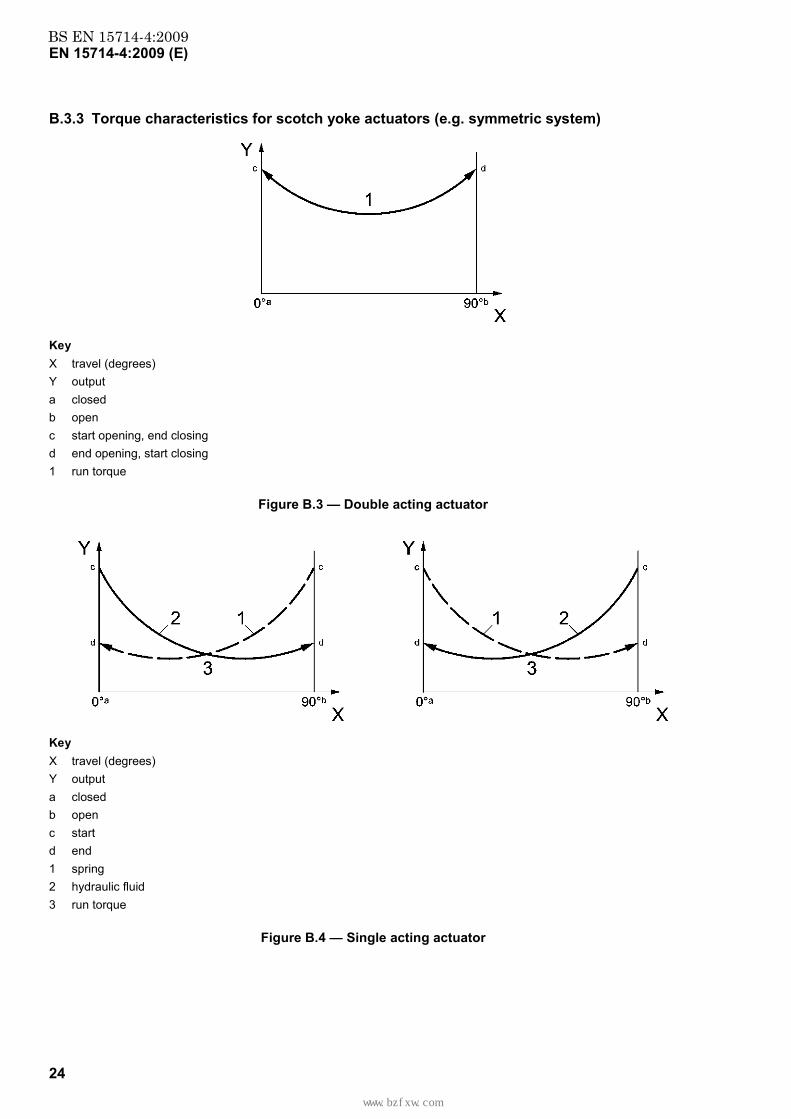
B.3.3 Torque characteristics for scotch yoke actuators (e.g. symmetric system)
Key X travel (degrees) Y output a closed b open c start opening, end closing d end opening, start closing 1 run torque
Figure B.3 — Double acting actuator
Key X travel (degrees) Y output a closed b open c start d end 1 spring 2 hydraulic fluid 3 run torque
Figure B.4 — Single acting actuator
标准分享网 www.bzfxw.com 免费下载

www.bzfxw.com
BS EN 15714-4:2009EN 15714-4:2009 (E)
25
Bibliography
[1] EN 1503-3, Valves — Materials for bodies, bonnets and covers — Part 3: Cast irons specified in European Standards
[2] EN ISO 3231, Paints and varnishes — Determination of resistance to humid atmospheres containing sulphur dioxide (ISO 3231:1993)
[3] EN ISO 4628-1, Paints and varnishes — Evaluation of degradation of coatings — Designation of quantity and size of defects, and of intensity of uniform changes in appearance — Part 1: General introduction and designation system (ISO 4628-1:2003)
[4] EN 10204, Metallic products — Types of inspection documents
[5] EN ISO 12100-1, Safety of machinery — Basic concepts, general principles for design — Part 1: Basic terminology, methodology (ISO 12100-1:2003)
[6] EN ISO 12100-2, Safety of machinery — Basic concepts, general principles for design — Part 2: Technical principles (ISO 12100-2:2003)
[7] EN 12516-3, Valves — Shell design strength — Part 3: Experimental method
[8] EN ISO 12944-2, Paints and varnishes — Corrosion protection of steel structures by protective paint systems — Part 2: Classification of environments (ISO 12944-2:1998)
[9] EN ISO 12944-5, Paints and varnishes — Corrosion protection of steel structures by protective paint systems — Part 5: Protective paint systems (ISO 12944-5:2007)
[10] EN 60534-6-2, Industrial-process control valves — Part 6-2: Mounting details for attachment of positioners to control valves — Positioner mounting on rotary actuators (IEC 60534-6-2:2000)
[11] ISO 7-1, Pipe threads where pressure-tight joints are made on the threads — Part 1: Dimensions, tolerances and designation
[12] 98/37/EU, Machinery Directive
[13] EN 15714-1, Industrial valves — Actuators — Part 1: Terminology and definitions
www.bzfxw.com
BS EN15714-4:2009
BSI GroupHeadquarters 389Chiswick High Road,London, W4 4AL, UKTel +44 (0)20 8996 9001Fax +44 (0)20 8996 7001www.bsigroup.com/standards
BSI - British Standards InstitutionBSI is the independent national body responsible for preparing BritishStandards. It presents the UK view on standards in Europe and at theinternational level. It is incorporated by Royal Charter.
Revisions
British Standards are updated by amendment or revision. Users of BritishStandards should make sure that they possess the latest amendments oreditions.
It is the constant aim of BSI to improve the quality of our products and services.We would be grateful if anyone finding an inaccuracy or ambiguity while usingthis British Standard would inform the Secretary of the technical committeeresponsible, the identity of which can be found on the inside front cover. Tel:+44 (0)20 8996 9000. Fax: +44 (0)20 8996 7400.
BSI offers members an individual updating service called PLUS which ensuresthat subscribers automatically receive the latest editions of standards.
Buying standards
Orders for all BSI, international and foreign standards publications should beaddressed to Customer Services. Tel: +44 (0)20 8996 9001. Fax: +44 (0)20 89967001 Email: [email protected] You may also buy directly using a debit/creditcard from the BSI Shop on the Website http://www.bsigroup.com/shop
In response to orders for international standards, it is BSI policy to supply theBSI implementation of those that have been published as British Standards,unless otherwise requested.
Information on standards
BSI provides a wide range of information on national, European andinternational standards through its Library and its Technical Help to ExportersService. Various BSI electronic information services are also available whichgive details on all its products and services. Contact Information Centre. Tel:+44 (0)20 8996 7111 Fax: +44 (0)20 8996 7048 Email: [email protected]
Subscribing members of BSI are kept up to date with standards developmentsand receive substantial discounts on the purchase price of standards. For detailsof these and other benefits contact Membership Administration. Tel: +44 (0)208996 7002 Fax: +44 (0)20 8996 7001 Email: [email protected]
Information regarding online access to British Standards via British StandardsOnline can be found at http://www.bsigroup.com/BSOL
Further information about BSI is available on the BSI website at http://www.bsigroup.com.
Copyright
Copyright subsists in all BSI publications. BSI also holds the copyright, in theUK, of the publications of the international standardization bodies. Except aspermitted under the Copyright, Designs and Patents Act 1988 no extract maybe reproduced, stored in a retrieval system or transmitted in any form or by anymeans – electronic, photocopying, recording or otherwise – without prior writtenpermission from BSI.
This does not preclude the free use, in the course of implementing the standard,of necessary details such as symbols, and size, type or grade designations. Ifthese details are to be used for any other purpose than implementation then theprior written permission of BSI must be obtained.
Details and advice can be obtained from the Copyright and Licensing Manager.Tel: +44 (0)20 8996 7070 Email: [email protected]
标准分享网 www.bzfxw.com 免费下载