valve actuators - jcn.com.br¡logos/redutores/redutores/... · available: cap or stem protectors...
TRANSCRIPT

Division of REGAL-BELOIT CORPORATIONV
alv
e A
ctuato
rs
Manual & Motorizable
BEVEL GEAR OPERATORS

Availab le:Cap or Stem Protectors(Not Shown)
Features & General Specifications
◆ AR Thrust Unit includes Bronze Stem Nut, can be threadedor machined by customer
◆ Sealed to IP67◆ Supplied with “Hammer Blow”
feature to help loosen stiff valves◆ Motor Drive Flanges available in
MSS SP-102◆ DE 2V Series has two ratios:
first with higher reduction for lockingsecond for completing this operation quickly
◆ Miter Gear Operators available to align handwheel to threaded stem
◆ 220 to 22,000 ft-lbs torque range◆ Thrust capabilities to 675,000 lbs◆ Housing can be sealed by the valve
stem protection tube or plug◆ Ideal for multi-turn applications ◆ Rising or non-rising stem designs◆ Optional Input Padlock Flange
Mastergear Bevel Gear Operators are used formulti-turn applications, gate, globe valves, and sluice gates.Designs are for either rising or non-rising stems.
Torque ranges from 220 ft-lbs to 22,000 ft-lbs and thrustcapabilities to 675,000 lbs. Gearboxes are provided ineither manual or motorizable versions.
Mastergear Bevel Gear Operatorsare completely weatherproof to IP67.The housing can be sealed by the valve stem protection tube or plug.
Valve ActuatorsFeatures
6
1
2
3
4
5
13
16
18
19
20
21
22
17
14
15
7
98
10
11
12
Item Component Material Description
1 Cover Cast Iron2 Bevel Wheel Forged Steel *3 Thrust Ring Steel4 Base “R” Forged Steel *5 Stem Nut Bronze 6 Stem Protection Steel Pipe7 Pinion Alloy Steel8 Motor Flange Ductile Iron9 Spacer Steel10 Ball Bearings Steel11 O-Ring Medium Nitrile12 Thrust Bearings Steel13 O-Ring Medium Nitrile14 Screw & Washers Hex Head 15 Gasket Fiber Gasket16 Key Steel 17 O-Ring Medium Nitrile18 Screw & Washers Hex Head 19 Ball Bearing Steel20 Gasket Fiber Gasket21 Grease Plug Steel22 Bearing Bronze
IP67 - Can be submerged inwater for a short period of time.
MSS SP-102 Pilot f or Centering
Hammer Blo w Option
* Ductile Iron on A90 and A1102

Valve ActuatorsOverview
AP1 ◆ Primary miterAR ◆ Thrust, bronze stem nut, can be threaded for rising stem or machined for non-risingARD or ◆ Two pinion shafts; one may be used for actuation, and second may transfer power to another actuatorARDMARM ◆ Motorizable, contains high quality ball bearings at the input shaft and hardened seats on the ring gearART ◆ Three pinion shafts; units permit transfer of power to two other actuatorsBM ◆ Bevel motor flangeC ◆ Cover plug, non-rising stemCS ◆ Stem cover for rising stemsCSI ◆ CS with mechanical position actuatorDE/DEM ◆ Spur gears available from sizes 24 to 110; motorizable versions also use higher grade ball bearingsDE2V ◆ Reducer units can be shifted to second ratio simply by pulling the handwheel toward you; permits high
ratio for releasing or seating valveV ◆ Handwheel
3
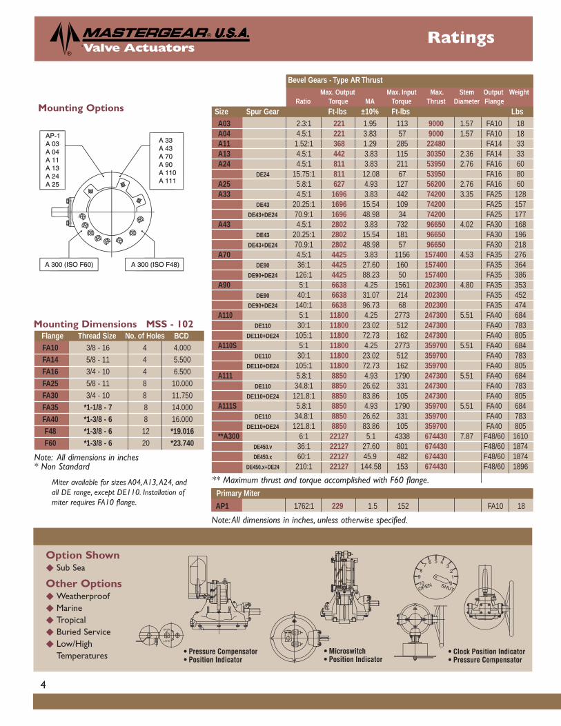
Valve ActuatorsRatings
Primar y Miter
Option Shown◆ Sub Sea
Other Options◆ Weatherproof◆ Marine◆ Tropical◆ Buried Service◆ Low/High
Temperatures
Size Spur Gear Ft-lbs ±10% Ft-lbs Lbs
Note: All dimensions in inches, unless otherwise specified.
** Maximum thrust and torque accomplished with F60 flange.Miter available for sizes A04,A13,A24, andall DE range, except DE110. Installation ofmiter requires FA10 flange. AP1 1.762:1 229 1.5 152 FA10 18
Note: All dimensions in inches* Non Standard
Mounting Dimensions MSS - 102
Mounting Options
Flang e Thread Siz e No. of Holes BCDFA10 3/8 - 16 4 4.000 FA14 5/8 - 11 4 5.500 FA16 3/4 - 10 4 6.500 FA25 5/8 - 11 8 10.000 FA30 3/4 - 10 8 11.750 FA35 *1-1/8 - 7 8 14.000 FA40 *1-3/8 - 6 8 16.000 F48 *1-3/8 - 6 12 *19.016F60 *1-3/8 - 6 20 *23.740
4
Bevel Gear s - Type AR ThrustMax. Output Max. Input Max. Stem Output Weight
Ratio Torque MA Torque Thrust Diameter Flang e
A03 2.3:1 221 1.95 113 9000 1.57 FA10 18A04 4.5:1 221 3.83 57 9000 1.57 FA10 18A11 1.52:1 368 1.29 285 22480 FA14 33A13 4.5:1 442 3.83 115 30350 2.36 FA14 33A24 4.5:1 811 3.83 211 53950 2.76 FA16 60
DE24 15.75:1 811 12.08 67 53950 FA16 80A25 5.8:1 627 4.93 127 56200 2.76 FA16 60A33 4.5:1 1696 3.83 442 74200 3.35 FA25 128
DE43 20.25:1 1696 15.54 109 74200 FA25 157DE43+DE24 70.9:1 1696 48.98 34 74200 FA25 177
A43 4.5:1 2802 3.83 732 96650 4.02 FA30 168DE43 20.25:1 2802 15.54 181 96650 FA30 196
DE43+DE24 70.9:1 2802 48.98 57 96650 FA30 218A70 4.5:1 4425 3.83 1156 157400 4.53 FA35 276
DE90 36:1 4425 27.60 160 157400 FA35 364DE90+DE24 126:1 4425 88.23 50 157400 FA35 386
A90 5:1 6638 4.25 1561 202300 4.80 FA35 353DE90 40:1 6638 31.07 214 202300 FA35 452
DE90+DE24 140:1 6638 96.73 68 202300 FA35 474A110 5:1 11800 4.25 2773 247300 5.51 FA40 684
DE110 30:1 11800 23.02 512 247300 FA40 783DE110+DE24 105:1 11800 72.73 162 247300 FA40 805
A110S 5:1 11800 4.25 2773 359700 5.51 FA40 684DE110 30:1 11800 23.02 512 359700 FA40 783
DE110+DE24 105:1 11800 72.73 162 359700 FA40 805A111 5.8:1 8850 4.93 1790 247300 5.51 FA40 684
DE110 34.8:1 8850 26.62 331 247300 FA40 783DE110+DE24 121.8:1 8850 83.86 105 247300 FA40 805
A111S 5.8:1 8850 4.93 1790 359700 5.51 FA40 684DE110 34.8:1 8850 26.62 331 359700 FA40 783
DE110+DE24 121.8:1 8850 83.86 105 359700 FA40 805**A300 6:1 22127 5.1 4338 674430 7.87 F48/60 1610
DE450.v 36:1 22127 27.60 801 674430 F48/60 1874DE450.x 60:1 22127 45.9 482 674430 F48/60 1874
DE450.x+DE24 210:1 22127 144.58 153 674430 F48/60 1896

Note: All dimensions in inches, unless otherwise specified. ISO and other bolt circle and pilot diameters available upon request* Non Standard** K2 dimension includes double reduction spur gears.
Valve ActuatorsDimensions
Primar y Miter — Miter available for sizes A04,A13,A24, and all DE range, except DE110. Installation of miter requires FA10 flange.
Bevel Gear s Spur Gear sA B C D E F G H J Bolt Pilot Max. Ratio K L M N O
NPT Circle Dia. Pilot K2** Thd. Depth
A03 1.97 4.60 2 4.29 7.09 2.83 1.77 .98 1.89 FA10 2.312 .120 N/AA04 1.57 3.94 2 4.09 7.09 2.32 1.38 .71 1.89 FA10 2.312 .120 N/AA11 1.97 4.76 3 6.22 7.09 3.90 1.77 .98 2.44 FA14 3.750 .160A13 1.57 4.84 3 5.31 8.90 3.11 1.38 .71 2.68 FA14 3.750 .160 N/AA24 1.97 5.67 3 6.37 10.12 3.82 1.77 .98 3.46 FA16 5.000 .190 DE24 15.75:1 10.0 1.97 1.77 .98 6.54A25 1.97 5.67 3 6.37 10.51 3.62 1.77 .98 3.46 FA16 5.000 .190 N/AA33 2.76 7.32 5 7.20 13.39 4.21 2.56 1.50 3.94 FA25 6.000 .190 DE43 20.25:1 11.81 1.97 1.77 .98 8.74
DE43+24 70.9:1 16.02 6.54A43 2.76 8.03 5 8.07 14.96 4.74 2.56 1.50 4.33 FA30 7.000 .190 DE43 20.25:1 12.48 1.97 1.77 .98 8.74
DE43+24 70.9:1 17.01 6.54A70 4.13 9.49 5 9.49 17.05 6.10 3.94 1.97 5.71 FA35 8.500 .190 DE90 36:1 14.33 1.97 1.77 .98 12.20
DE90+24 126:1 18.66 6.54A90 6.10 11.30 6 10.51 20.67 6.30 5.91 1.97 6.10 FA35 8.500 .190 DE90 40:1 16.10 1.97 1.77 .98 12.20
DE90+24 140:1 20.47 6.54A110 6.10 12.80 6 12.80 23.70 8.78 5.91 1.97 8.07 FA40 9.000 .320 DE110 30:1 17.76 2.76 2.56 1.50 13.07
DE110+24 105:1 22.24 1.97 1.77 .98 6.54A110S 6.10 12.80 6 12.80 23.70 8.78 5.91 1.97 8.07 FA40 9.000 .320 DE110 30:1 17.76 2.76 2.56 1.50 13.07
DE110+24 105:1 22.24 1.97 1.77 .98 6.54A111 6.10 12.80 6 12.80 23.70 8.78 5.91 1.97 8.07 FA40 9.000 .320 DE110 30:1 17.76 2.76 2.56 1.50 13.07
DE110+24 105:1 22.24 1.97 1.77 .98 6.54A111S 6.10 12.80 6 12.80 23.70 8.78 5.91 1.97 8.07 FA40 9.000 .320 DE110 30:1 17.76 2.76 2.56 1.50 13.07
DE110+24 105:1 22.24 1.97 1.77 .98 6.54A300 6.69 17.68 10 18.82 33.07 13.31 6.30 3.15 12.05 *F48 *14.567 *.315 DE300+450.v 36:1 25.94 2.76 2.56 1.50 19.29
DE300+450.x 60:1 25.94 2.76 2.56 1.50 19.29DE300+450.x+DE24 210:1 30.39 1.97 1.77 .98 6.54
AP1 2 3.94 N/A 4 6.77 3.07 1.77 .98 2.52 FA10 2.312 1.20 N/A
5

Valve ActuatorsMotorizable Flanges
Manual OperationInput shaft sleeve
bearings
Bevel Motor Flange Sizes According to MSS - 102
* ISO
Note: All flange dimensions in inches.L2/L3 dimension includes double reduction spur gears.
Motor OperationInput shaft ball
bearings
b4 b5 b6 c3 D1 D2 D3 d5 d10 e2 h4 h5 L5 L6 t2FA07 .1968 .098 .826 M8 3.54 2.166 2.750 .3937 .630 4 .120 .3937 1.574 1.378 .7086FA10 .2362 .098 .826 M8 4.92 2.312 4.000 .4724 .787 4 .120 .3937 1.968 1.771 .8858FA14 .3149 .098 .945 M10 6.89 3.750 5.500 .7086 1.181 4 .160 .5905 2.756 2.560 1.2992FA16 .4724 .098 .945 M10 8.25 5.000 6.500 .8661 1.575 4 .190 .5905 3.543 3.346 1.6929FA25 .5511 .196 1.062 M12 11.81 6.000 10.000 .7086 1.968 8 .190 .7086 4.330 3.937 2.1062FA30 .0786 .196 1.062 M12 13.78 7.000 11.750 .8661 2.362 8 .190 .7874 4.724 4.330 2.5196FA35 .8661 .196 1.062 M12 16.33 8.500 14.000 1.2598 3.150 8 .190 .9842 5.313 4.921 3.3464FA40 1.1023 .196 1.062 M12 18.70 9.000 16.000 1.4960 3.937 8 .320 1.1023 7.086 6.693 4.1732*F48 22.04 14.566 19.016 1.4960 12*F60 18.504 23.740 1.4960 20
6
With Flang e MSS-102FA07 FA10 FA14 FA16 FA25 FA30 FA35 FA40
Size Without Flang eAP1M A 3.937 A1 6.181 6.496A03M A 4.606 A1 6.850 6.850A04M A 3.937 A1 5.630 5.433A11M A 4.763 A1 6.850 6.929A13M A 4.842 A1 6.811 6.889 5.708
A24M A 5.669 A1 7.952 8.267 7.086L 10.000 L1 12.480 12.795
A25M A 5.669 A1 7.952 8.267 7.086A 7.322 A1 10.393 10.944 8.740
A33M L 11.614 L1 14.291 14.606 13.385L2 16.023 L3 18.425 18.740A 8.031 A1 11.102 11.653 9.448
A43M L 12.322 L1 15.000 15.315 14.094L2 16.732 L3 19.133 19.448A 9.488 A1 13.425 10.708 10.708
A70M L 14.291 L1 16.771 17.086 15.705L2 18.661 L3 21.141 21.456A 11.299 A1 15.196 12.480 12.480
A90M L 16.102 L1 18.543 18.858 17.677L2 20.472 L3 22.913 23.228
A110M- A 12.795 A1 16.692 13.976 13.976 13.976A111M L 17.755 L1 20.196 20.511 19.330A110SM- L2 22.204 L3 24.645 24.960A111SMA 17.677 A1 20.314 20.629
A300M L 25.944 L1 27.480L2 30.393 L3 32.952 33.267

Handwheel
Shaft
Columns
Stems
Padlock Flange
Portable powered drive
Cover tubetype C
Position indicator fornon-rising stem
Cover tubetype CS
Cover tube withposition indicatortype CSI
PlatesManual drive
Handle(option)
Valve ActuatorsOptions
7
Information in this brochureis believed to be accurate.Mastergear reserves the right toalter specifications without notice.Please contact factory for certifieddrawings or specifications.
2885P-JL-10/01-3M-UL
Opperman Mastergear, Ltd.Hambridge RoadNewbury, Berkshire England RG145TS tel (44) 1635/811500fax (44) 1635/811501e-mail [email protected]
Mastergear (GmbH)Siemensstraße 16D-61267 Neu-AnspachGermanytel (49) 6081/94300fax (49) 6081/943030e-mail [email protected]
Costruzioni Meccaniche Legnanesi S.r.L. (CML)Via Del Brugo 520025 Legnano (MI)Italytel (39) 331-548-847fax (39) 331-592-800email [email protected]
Valve Actuators
Division of REGAL-BELOIT CORPORATION5466 E. Rockton Road, South Beloit, IL 61080800-722-7643 • 815-389-4004 • Fax 815-389-8383www.mastergearworldwide.come-mail: [email protected]
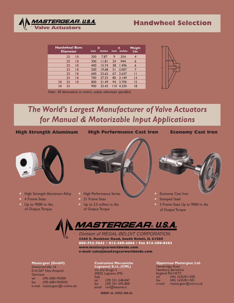
The World’s Largest Manufacturer of Valve Actuatorsfor Manual & Motorizable Input Applications
25 18 200 7.87 9 .354 425 18 300 11.81 24 .944 625 18 400 15.74 38 1.496 625 18 500 19.68 51 2.007 725 18 600 23.62 67 2.637 1125 18 700 27.55 80 3.149 13
38 25 18 800 31.49 94 3.700 1538 25 900 35.43 110 4.330 18
Handwheel BoreDiameter
D Amm inches mm inches
WeightLbs
Handwheel Selection
Note: All dimensions in metric, unless otherwise specified.
High Performance Cast Iron
• High Performance Series
• 21 Frame Sizes
• Up to 2.5 million in.-lbs.of Output Torque
Economy Cast Iron
• Economy Cast Iron
• Stamped Steel
• 3 Frame Sizes Up to 9000 in.-lbs of Output Torque
High Strength Aluminum
• High Strength Aluminum Alloy
• 4 Frame Sizes
• Up to 9000 in.-lbs.of Output Torque