using hdsdr with fcd - ml&s martin lynch and sons · pdf filecommercial radio receiver and...
TRANSCRIPT

UsingHDSDRwiththeFUNcubeDongle Page1
UsingHDSDRwiththeFUNcubeDongleDocumentdate: 29May2011
Contributors: HowardLong,G6LVB,FCD#1RobStyles,M0TFO,FCD#15MichaelWillis,G0MJW,FCD#108MarkHammond,N9MHMikeRupprecht,DK3WNFrankDeWilde,PH2M,FCD#111BruceGreenleaf,KF1ZGarySanders,WB0BZR
Editor: SteveBelter,N9IP,FCD#408
AMSAT‐UK’s FUNcube is an educational single cubesat project with the goal of enthusing and educating
young people about radio, space, physics and electronics. FUNcube will carry a UHF‐to‐VHF linear
transponder that can be used by Radio Amateurs worldwide for SSB and CW communications.
Measuring just 10 x 10 x 10 cm, and with a mass of less than 1kg, it will be the smallest ever satellite to
carry a linear transponder and the choice of frequencies will enable Radio Amateurs to use their existing
VO‐52, DO‐64, HO68 and similar stations. See www.funcube.org.uk for more information on the project
goals and the FUNcube satellite.
The FUNcube Dongle (FCD) is a small Software Defined Receiver (SDR) with a built‐in sound card that
was created to provide a low‐cost way for schools and individuals to listen to the FUNcube satellite and
receive telemetry from the on‐board experiments. The FCD connects to an antenna and the USB port of
a laptop or desktop personal computer (PC) to display telemetry and messages in an interesting way.
See www.funcubedongle.com for more information on the FCD.
HDSDR is a versatile program designed to work with multiple SDR hardware platforms. It takes the I/Q
data from an SDR, displays waterfall and spectrum graphs, and demodulates the signals. It has a
number of significant features, all implemented in software. HDSDR runs in a Microsoft Windows
environment, including XP, Vista, and Windows 7. See www.hdsdr.de for more information on HDSDR.
The "Pro" version of the FCD is an incredible tool capable of capturing an 80 kHz slice of the radio
spectrum, tunable between 64 MHz and 1.7 GHz. Because it is an SDR, the PC software can implement a
wide‐range of demodulation and filtering schemes. The FCD is not a drop‐in replacement for a US$3,000
commercial radio receiver and in many cases will require some front‐end filtering to handle RF
interference.
This document is intended to help new FUNcube dongle owners get the FCD working with HDSDR. It is
aimed at individuals with a solid background in both radio electronics (e.g., amateur radio operators)
and personal computer software. It does not contain a detailed theory of operation for the FCD nor a
user guide for HDSDR.

UsingHDSDRwiththeFUNcubeDongle Page2
FCDDesignGoalsandBasicOperation
A little background information may help new owners better understand the operational steps that are
presented later in this document.
There were several design goals for the FUNcube dongle and a number of engineering compromises that
were made to accomplish these goals:
1. As mentioned earlier, the primary goal was to create a very low cost ground station receiver for
the FUNcube satellite. To minimize the cost, it was decided to build an SDR that would not
require a separate radio, would not require a sound card, and would connect to standard
classroom PCs.
2. A USB interface was chosen that appears to most Operating Systems (including Microsoft
Windows, Apple OS/X, and Linux) as a standard sound card that uses built‐in sound card drivers.
A custom device driver is not required.
3. The FCD was designed to work with a wide variety of SDR programs, including WinRad, WRPlus,
HDSDR, Rocky, LinRad, SpectraVue, KGKSDR, and PowerSDR. These SDR programs, some
commercial and some free, implement the User Interface, including a virtual “front panel” and
multiple demodulation modes (e.g., AM, FM, SSB, and CW).
4. To further minimize the cost, the number of components in the FCD was minimized, a very
compact package was chosen, and the circuit was implemented on a double‐sided PCB. The FCD
can be mass produced and the amount of tuning, rework, and testing has been minimized.
The on‐board sound card and USB computer interface of the FCD have two logical components, the
control interface and the I/Q data from the receiver.
The I/Q data, which look to the operating system like a 16‐bit stereo audio stream with 96,000 samples
per second, provide the necessary information for the SDR software to display and demodulate the RF
signals. In the HDSDR program, you will chose the FCD as the sound card for the I/Q data.
The control interface is used to set the RF frequency of the FCD tuner and a number of other
parameters. A special software interface (a Windows Dynamic Link Library or DLL) is used to allow
HDSDR to communicate with this control interface. The ExtIO_FCD_G0MJW.dll file translates between
the native commands of the FCD and the “standard” commands used by several SDR programs,
including HDSDR. HDSDR looks for a file named “ExtIO*.dll” to provide this standard command
interface. In the HDSDR program, you’ll choose the ExtIO “input device” to allow HDSDR to tune the
FCD.
Step1:JointheFUNcubeYahoo!Group
The User Guides and most of the software for the FCD are in the Files section of the FUNcube Yahoo!
group. If you haven’t already done so, join the FUNcube Yahoo! group at:
http://uk.groups.yahoo.com/group/funcube/

UsingHDSDRwiththeFUNcubeDongle Page3
In the Files section of the FUNcube Yahoo! group in the User Guides directory, you can download the
PDF file titled “The FCD – An Introduction.pdf” which provides additional background information.
Step2:FCDFirmwareUpgrade
To date, all of the FUNcube Dongles have been shipped with firmware that facilitates the rapid testing of
the assembled unit, Version 18b (also called 18.02 in some places). To use the FCD with HDSDR, you
first need to upgrade this firmware to the current production firmware, Version 18f (18.06) or a later
version.
Go to the Files section of the FUNcube Yahoo! group, then select the User Guides directory. Download
the PDF file titled “FCD Firmware Update” and carefully follow the instructions.
Microsoft classifies a sound card as a Human Interface Device or HID. One of the programs you’ll use to
test the operation of the FCD and start the firmware upgrade process is called FCHID.exe. The name of
this program is an acronym for Fun Cube Human Interface Device.
Step3:CopytheDLLtoYourPC
Once you’ve upgraded the firmware in your FCD, use Windows Explorer to create a directory on your PC
to hold HDSDR. The suggested location is C:\Program Files\HDSDR.
Note that you’ll likely need Administrator privileges to install the software and to run it. Even with
Administrator privileges, you may be asked multiple times if it is OK to install programs or copy files to
your computer. Finally, you’ll need Administrator privileges to run the program.
Mike Willis, G0MJW, with the assistance of Howard Long and Rob Styles, has written a DLL that
implements the standard command interface used by several SDR programs, including HDSDR. Go to
the Files section of the FUNcube Yahoo! group, then select the “ExtIO_FCD.dll G0MJW” link. Copy the
latest version of the file ExtIO_FCD_G0MJW.dll into the HDSDR directory that you just created on your
PC.
Step4:CopytheHDSDRInstallationProgramtoYourPC
Go to the Files section of the FUNcube Yahoo! group, then select the “SDR Software” link. Copy the file
HDSDR_install.exe into the HDSDR directory.
Using Windows Explorer, check the HDSDR directory on your PC. You should have two files:
ExtIO_FCD_G0MJW.dll
HDSDR_install.exe
If you don’t have these two files, revisit Steps 3 and 4 to solve the problem before you continue.

UsingHDSDRwiththeFUNcubeDongle Page4
Step5:InstallHDSDR
If either the FCHID or FCHIDBL programs are running from upgrading the firmware or other experiments,
stop them now.
Run the program HDSDR_install.exe.
Follow the installation program’s instructions and install the program in the C:\Program Files\HDSDR
directory. Allow the installer to create a startup group “HDSDR” and to place a shortcut on the desktop.
Uncheck the box to start HDSDR when the installation completes.
Using Windows Explorer, check the HDSDR directory on your PC. You should now have nine files:
delete_settings.cmd
ExtIO_FCD_G0MJW.dll
HDSDR.exe
HDSDR_install.exe
hdsdr_keyboard_shortcuts.htm
HDSDR_release_notes.txt
unins000.dat
unins000.exe
WinRadPX.dll
You can delete the installation program HDSDR_install.exe if you wish. The HDSDR program is the file
HDSDR.exe.
Step6:ConfiguringHDSDR
To configure HDSDR for the first time, disconnect the FCD from your PC’s USB port, then plug it in again.
(The reason for this dance is explained under troubleshooting below.)
Now start HDSDR by double‐clicking on the Desktop Shortcut, or using the Windows Start menu, or
double‐clicking on the HDSDR.exe file name.
In the lower left corner of the HDSDR “virtual front panel”, you’ll see the following buttons:

UsingHDSDRwiththeFUNcubeDongle Page5
The Sound Card Selection menu may appear in the middle of your screen the first time you run HDSDR.
If it doesn’t, use the mouse to select the “Soundcard [F5]” button, or press the “F5” key. You’ll see a
screen like this:
You’ll need to make two selections on this menu. HDSDR needs to know which device and sound card
will supply the I/Q data when you are listening to real‐time data, i.e., the FCD’s on‐board sound card.
The program also needs to know where you want to send the demodulated signal (e.g., sending the
conversation from your local repeater to the speakers in your laptop).
For the “Input Sound Card”, select the FUNcube Dongle as the real‐time source of the I/Q data. In the
picture above, this selection is titled “Microphone (FUNcube Dongle V1.0”.
For the “Output Sound Card”, select the sound card where you want to send the demodulated signal.
This would be your speakers if you wanted to listen to an FM or SSB conversation. If you are planning to
use a program to decode telemetry, CW, packet, or SSTV pictures, this is where you could chose the
Virtual Audio Cable (VAC) software or a sound card that you’ll connect to a TNC or loop to the decoding
software.
Once you’ve chosen the Input and Output Sound Cards, use the mouse to select “OK”.

UsingHDSDRwiththeFUNcubeDongle Page6
Next, use the mouse to select the “Samplerate [F6]” button, or press the “F6” key. You’ll see a screen
like this:
Using this menu, you’ll specify to HDSDR how many samples per second are in the I/Q data stream, and
how many samples per second you want in the demodulated output.
Under the “Input” column, select “96000” because the FCD produces 96,000 samples per second.
Under the “Output” column, you should select 12000, 24000, 48000, or 96000 samples per second. The
maximum frequency (in Hertz) of the demodulated output is half of the samples per second. So if you
select “12000”, the maximum frequency in the demodulated output will be 6,000 Hz or 6 kHz. This is
usually an appropriate choice for SSB, CW, and 1200 baud packet. For broadcast FM and higher speed
data modes, you should probably choose a faster output sampling rate. If you’re not sure what to pick,
start with “12000”; you can always change it later.
Once you’ve chosen the Input and Output Sampling rates, use the mouse to click the “X” in the upper
right corner of the menu.

UsingHDSDRwiththeFUNcubeDongle Page7
Now use the mouse to select the “Options [F7]” button, or press the “F7” key. Move the mouse over
the first choice on the Options menu “Select Input” and a second menu will appear:
The “WAV file…” choice allows you to choose a WAV file that has been recorded earlier. This is great for
demonstrating the program, listening to a satellite pass you recorded while you were sleeping, or testing
the performance of various filters, demodulators, TNCs, and decoding software.
The “Sound Card” choice uses the input sound card you selected above for the I/Q data (you selected
the FCD’s on‐board sound card), but doesn’t connect the tuning controls of HDSDR to the FCD. You can
pick this if you want another program to control the frequency of the FCD, for example, FCHID.exe or
SATCONTROL_FCD.exe.
The bottom choice “Open Input Mixer…” opens a Microsoft Windows operation system window that
allows you to control the operation of the audio devices on the computer. Under Windows 7, this brings
up the “Sound” window; on XP this brings up the “Recording Control” window.
The “FCD – G0MJW ExtIO Control” choice uses the input sound card you selected above for the I/Q data
(you selected the FCD’s on‐board sound card), and allows HDSDR to control the frequency of the FCD.
Using the mouse, select “FCD – G0MJW ExtIO Control”.
If you don’t have the “FCD – G0MJW ExtIO Control” menu choice, but instead see “No ExtIO DLL found”
or “Hardware not ready!”, refer to the Troubleshooting section below.

UsingHDSDRwiththeFUNcubeDongle Page8
Step7:HDSDR’sVirtualFrontPanel
Once you’ve completed Step 6, you’re ready to start listening to your FCD. Connect an antenna to the
FCD’s SMA antenna connector.
Use the mouse to select the “Start [F2]” button, or press the “F2” key. Things should start to happen all
over the screen and you should hear noise from your speakers (if the sound isn’t turned down or
muted).
HDSDR is an amazing program with many features and controls. This is a brief tour of the HDSDR’s
Virtual Front Panel to get you started with the FCD and HDSDR.
The upper half of the HDSDR screen is divided into two parts. The upper part of the upper half is the
“waterfall” display and the lower part is the “spectrum” display. Between the two displays is a ruler that
is marked with the frequency in kHz. The left edge of the spectrum display is calibrated in dB, from 0 at
the top to ‐140 at the bottom. These upper displays show the entire 96 kHz bandwidth from the FCD, of
which about 80 kHz is usable.
The upper waterfall display shows the signals heard over the past 20 seconds; brighter colors represent
stronger signals. With experience, you’ll be able to recognize the look or signature of SSB, CW, and FM
signals within the passband. If you click the mouse in the upper waterfall, it will change the Tune
frequency. The scrolling the mouse wheel will make fine adjustments to the frequency.
The upper spectrum display shows an instantaneous graph of the signal strengths within the passband.
When you move the cursor over the spectrum display, HDSDR will show you the cursor coordinates in
dB and kHz.
UsingHDSDRwiththeFUNcubeDongle Page9
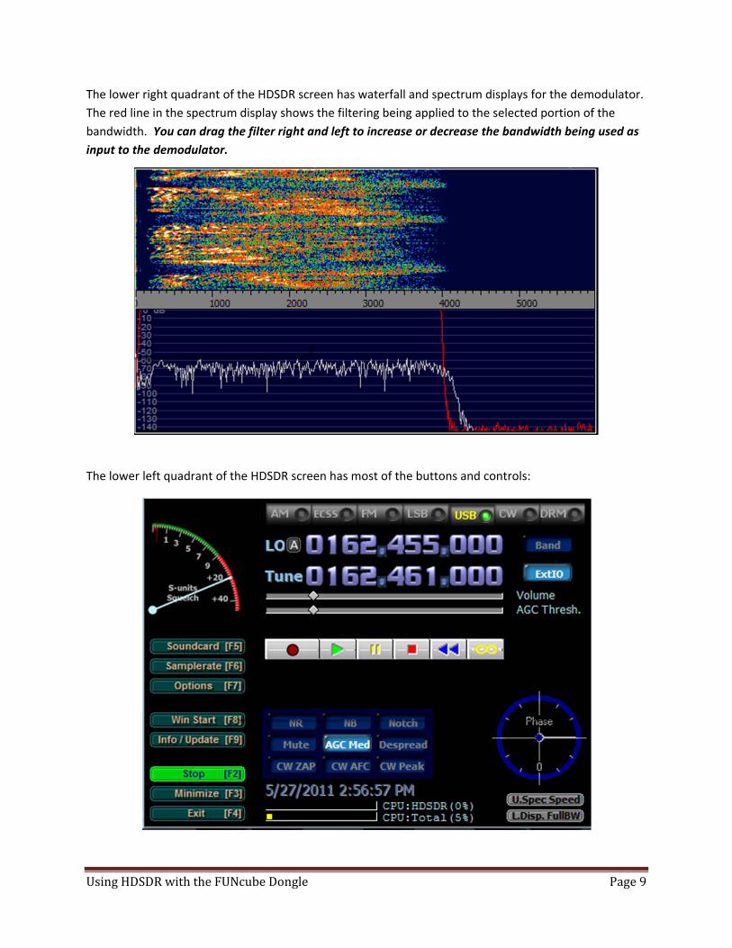
The lower right quadrant of the HDSDR screen has waterfall and spectrum displays for the demodulator.
The red line in the spectrum display shows the filtering being applied to the selected portion of the
bandwidth. You can drag the filter right and left to increase or decrease the bandwidth being used as
input to the demodulator.
The lower left quadrant of the HDSDR screen has most of the buttons and controls:

UsingHDSDRwiththeFUNcubeDongle Page10
Along the top are the buttons to select the demodulation scheme: AM, ECSS, FM, LSB, USB, CW, and
DRM.
Use the LO (Local Oscillator) frequency to set the midpoint of the FCD’s 96 kHz passband. You can
change the frequency by placing the cursor over a digit. Clicking the left mouse button increments that
digit, the right button decrements, and scrolling the mouse wheel allows you to increase or decrease the
digit. If you’d prefer to type the new LO frequency, Ctrl‐O (letter “O”) will bring up this dialog box:
There are two LO registers or memories, “A” and “B”. You can switch to the other LO by clicking on the
A or B to the right of “LO” or by typing Ctrl‐V.
The “Band” button can be used to jump to a particular frequency band. Note that the FCD is specified to
work from 64 MHz to 1.7 GHz. Since HDSDR works with lots of different SDR hardware platforms, it will
allow you to choose frequencies far outside of the operating range for the FCD.
The Tune frequency sets the location of the demodulator, which must be within the passband. You can
change the Tune frequency by clicking in the upper waterfall display, by using the mouse to point to
digits in the frequency display, or by typing Ctrl‐T.
Ctrl‐Q is the “Quick Tune” shortcut which will bring up a dialog box to allow you to type a new Tune
frequency. When you click OK, both the LO and Tune frequencies will be changed with the LO frequency
being set just below the Tune frequency to avoid the center or DC spike.
Under the Tune frequency are two sliders which allow you to change the Volume and adjust the AGC
Threshold. There is also a “Mute” button in the 3x3 button array above the date and time. Note that
the AGC slider will disappear if you choose “FM” demodulation.
Below the sliders are six buttons that control the record and playback functions of HDSDR. From left to
right, they are Record, Play, Pause, Stop, Rewind, and Loop. You can configure the recording settings by
clicking the right mouse button when pointing to the Record button. You can also go to the Options [F7]
menu and select “Recording Settings/Scheduler”.
If everything seems to be working, you can skip the Troubleshooting section and proceed to Step 8.

UsingHDSDRwiththeFUNcubeDongle Page11
Troubleshooting
Here is a list of some of the common problems experienced by FCD owners and suggested solutions.
Problem: On the Select Input menu, the third choice is “Hardware not ready!” instead of “FCD – G0MJW
ExtIO Control”.
Solution: Make sure the FCD is plugged into your computer. Try using a different USB port. Use the
FCHID.exe program to make sure you successfully upgraded the FCD firmware to Version 18f or
later. Version 18b which is installed on the FCD when you receive it will not work with HDSDR.
Problem: On the Select Input menu, the third choice is “No ExtIO DLL found” instead of “FCD – G0MJW
ExtIO Control”.
Solution: Make sure the ExtIO_FCD_G0MJW.dll and HDSDR.exe files are in the same directory, normally
the C:\Program Files\HDSDR. See the section “Step 3: Copy the DLL to your PC” above.
Problem: HDSDR’s “Ext IO” button is greyed out and doesn’t work.
Solution: Make sure the ExtIO_FCD_G0MJW.dll and HDSDR.exe files are in the same directory. Make
sure the FCD is plugged into your computer. Try using a different USB port. Use the FCHID.exe
program to make sure you successfully upgraded the FCD firmware to Version 18f or later.
Problem: HDSDR seems to be receiving, but the waterfall and spectrum displays don’t change when I
change the LO Frequency.
Solution: Make sure the ExtIO_FCD_G0MJW.dll and HDSDR.exe files are in the same directory. Make
sure you’ve selected “FCD – G0MJW ExtIO Control” on the Select Input menu under the Options
[F7] menu. Use the FCHID.exe program to make sure you successfully upgraded the FCD
firmware to Version 18f or later.
Problem: My FCD was working fine, but now I’m seeing images above and below the center frequency.
Solution: When the operating system is restarted without turning off the PC, the FCD does not always
reinitialize correctly and the I and Q samples get out of sync. Simply unplug the FCD from the
USB port, then plug it in again.
Problem: My FCD has images above and below the center frequency. Disconnecting and reconnecting
the FCD didn’t solve the problem.
Solution: See the section below “Minimizing Images”.
Problem: My FCD has a large spike at the center frequency.
Solution: See the section below “Minimizing the Center Spike”.

UsingHDSDRwiththeFUNcubeDongle Page12
Problem: My FCD can only hear very strong signals, and the noise floor is higher than ‐80 dB.
Solution: You are probably getting too much signal, probably from frequencies outside of the current
FCD passband. Too much signal overloads the front end and raises the noise floor. Typical
causes are RFI from the computer or nearby pager and broadcast stations. For computer RFI, try
using a USB extension cable to move the FCD away from the computer. For strong out‐of‐band
transmitters, see the section below “Front‐End Filtering”.
Problem: My FCD can only hear very strong signals, but the noise floor is ‐90 dBm or below.
Solution: Check your antenna. Under normal circumstances, the FCD does require a real antenna. Each
FCD is tested for 0.15uV sensitivity for 12dB SINAD NBFM at 145MHz and 435MHz before
shipping.
Problem: My FCD seems to be working, but the frequency is off.
Solution: See the section below titled “Calibrating the Local Oscillator”.
Problem: The antenna connector on my FCD is very warm.
Solution: This is normal. Most of the power dissipation in the FCD is in the tuner IC and the resulting
heat is conducted to the SMA connector.
Problem: When I tune into an FM broadcast station, the audio is very distorted.
Solution: Make sure that you’ve selected “FM” as the demodulator. Set both the LO and Tune settings
to the frequency of the broadcast station. On the Samplerate [F6] menu, set the output
sampling rate to 96000. Finally, use your mouse to drag the right edge of the filter in the lower
right window all the way to the right. Note that the maximum bandwidth of the FCD is not wide
enough for high‐fidelity FM broadcasts.
Problem: I see and hear a click in the audio every 6‐15 seconds.
Solution: This is a known problem for some FCD caused by the FCD clock and the USB clock being
slightly different which results in a buffer underflow or overflow every 6‐15 seconds. A solution
is being investigated.
Problem: I can’t set the Local Oscillator (LO) to the exact frequency I want.
Solution: While you can set the Tune value to any frequency with 1 Hertz precision, the FCD LO cannot
tune 1Hz steps; the actual step size is determined by the fractional n‐synthesis of the phase‐
locked loop. In general, you can tune the LO from about 52 MHz to 2,100 MHz with a gap
between 1,100 and 1,270 MHz.
Problem: The FCD passband is 96 kHz, but I only see about 80 kHz.
Solution: The analog‐to‐digital converter (ADC) decimation filters limit the usable bandwidth to about
80 kHz.

UsingHDSDRwiththeFUNcubeDongle Page13
If you are still experiencing problems that are not solved by the list above, check the message archive on
the FUNcube Yahoo! group to see if someone else has experienced your problem. If you don’t see your
problem and a solution in the archive, send a message to the FUNcube Yahoo! group. Chances are good
that one or more of the 1000+ members of the group can help you.
Step8:CalibratingtheLocalOscillatorFrequency
If you tune a broadcast station of known frequency with the FCD, you’ll quickly figure out that the LO
and Tune frequencies are off. This is normal and the ExtIO DLL will allow you to enter a correction for
the frequency and save it for future use.
On the HDSDR virtual front panel, just to the right of the Tune frequency, there is a button labeled
“ExtIO”. Clicking on this button will make the FCD Control – G0MJW window visible (it is usually hidden
by the HDSDR window):
Among other things, this shows the version of the firmware on the FCD, 18.08 in the picture above or
version 18h. (“h” is the eighth letter of the alphabet; the “18.08” in the version number means 18h.)
Clicking the “Debug” box will allow you to monitor the results from the FCD in response to LO frequency
change commands from HDSDR.
Clicking the “Expert” box will show the following window, which contains controls similar to those
you’ve seen in the FCHID.exe program:

UsingHDSDRwiththeFUNcubeDongle Page14
Adjusting these settings is covered in this and later sections. One important thing to note is that you can
save the adjustments you make in this window. The “File” menu allows you to “Save Default” (settings
loaded automatically the next time you start HDSDR), “Save As” (settings saved to a file), and “Load” (to
reload settings that you saved).
The crystal offset correction should be a one‐time operation, once you find the offset of your FCD it
should remain valid for the entire frequency range. Before adjusting the crystal offset, allow your
dongle to warm up by connecting it to your computer and running HDSDR for at least 60 minutes.
To correct the frequencies, you can use a service monitor if you’re lucky enough to have one, or just find
a local transmitter whose frequency accuracy you trust. For example, in the United States, the NOAA
weather stations cover most of the country. These are narrowband FM transmitters broadcasting on
one of 7 frequencies: 162400, 162425, 162450, 162475, 162500, 162525, or 162550 kHz.
You adjust the crystal offset correction by changing the number in the “Frequency Offsets Error (ppm)”
box. In this case, “ppm” is an acronym for parts per million.
One method of finding the right crystal offset is to just fiddle with the Error value until the Tune value
shows the correct frequency when the demodulator is tuned to the reference signal; typical numbers
are between ‐200 and +200. (The default for ExtIO is ‐106 because many of the early FCDs were around
this number. The best value for FCD #408 is ‐117.) The Fiddle procedure isn’t the recommended
approach, but a lot of people have done it this way.
Important Note: After you type a new value into the Error (ppm) box, press the Tab key to move the
cursor out of the box, then change the LO in HDSDR and change it back. A change to the Error
correction does not get communicated to the FCD until HDSDR sends a new LO value. Note too that
changes to the Tune frequency are not sent to the FCD. Short cut: If you have LO‐A and LO‐B set to
different frequencies, you can force a LO change by typing Ctrl‐V twice.
A better method to adjust the crystal offset is to simply calculate the error and type it into the Error box.
1. Click the “ExtIO” button make the “FCD Control – G0MJW” window visible, then check the
Expert box so that the Settings window is visible. Now set both Frequency Offsets, IF (kHz) and
Error (ppm) values to 0. Change the LO frequency, then change it back so that the FCD gets the
new crystal offset of 0 (e.g., type Ctrl‐V twice).
2. Type Ctrl‐Q, then type the frequency of your reference signal into the box and click OK. For
example, if your reference broadcast station is at 162475 kHz, use the Ctrl‐Q Quick Tune feature
to enter 162475. This should get you close enough that you can see your reference signal in the
upper waterfall display.
3. Move the mouse cursor over the carrier of your reference signal in the upper waterfall display
and click the mouse button. The Tune frequency display now shows the uncorrected FCD
frequency for the reference signal. In our example, suppose the Tune frequency after this step
is 162456 kHz.
4. Subtract the reference frequency from the Tune frequency to calculate the frequency error. In
our example, the error is 162456 – 162475 = ‐19 kHz at 162475 kHz.

UsingHDSDRwiththeFUNcubeDongle Page15
5. To convert to ppm, divide the error in kHz by the reference in kHz, then multiply by one million.
In our example ‐19 / 162475 x 1000000 = ‐116.941 or ‐117 ppm.
6. Type the computed ppm into the Error (ppm) box, press the Tab key to move the cursor out of
the box, then change the LO in HDSDR and change it back.
7. Check your work by moving the mouse cursor over the carrier of your reference signal in the
upper waterfall display and click the mouse button. The Tune frequency display now shows the
HDSDR frequency for the reference signal. In our example, the Tune frequency should now be
162475 kHz, the same as the actual reference signal.
8. Once you have the crystal offset adjusted to your satisfaction, save it! In the ExtIO Settings
window, select “Save Default” under the File menu. This correction will now be applied
whenever you start HDSDR with the G0MJW ExtIO.
Please note that the FCD LO cannot tune 1Hz steps; the actual step size is determined by the fractional
n‐synthesis of the phase‐locked loop. This means even after calibration you will not often get an exact‐
to‐the‐Hz correction. It is good enough for most purposes but fine tuning ought to be done using the
Tune frequency setting, not by changing the LO.
Step9:MinimizingtheCenterSpike
There is normally a spike in the center of the passband on both the waterfall and spectrum displays.
This is an artifact caused by a small DC (direct current) offset at 0 volts for the I and Q analog‐to‐digital
converters. You can normally reduce, but not eliminate, this spike by adjusting the DC Offset (%)
parameters for I and Q in the ExtIO Settings window.
Like the crystal offset, the DC offset adjustments should be one‐time operations. Before adjusting the
DC offset, allow your dongle to warm up by connecting it to your computer and running HDSDR for at
least 60 minutes.
Unlike the Error (ppm) value, changes to the I and Q adjustment values for DC Offset (%) take effect
almost immediately without having to change the LO or jump through any other hoops.
Unfortunately, the most common way of making the center spike adjustments with HDSDR involves an
iterative trial and error process:
1. Disconnect the antenna from the FCD. If you have one, connect the FCD SMA antenna
connector to a 50‐ohm dummy load.
2. Click the “ExtIO” button make the “FCD Control – G0MJW” window visible, then check the
Expert box so that the Settings window is visible. Move both windows so that you can see the
center spike in the upper spectrum display.
3. Using the up and down arrow buttons next to the “DC Offset (%) I” box, find a number (positive
or negative) that reduces the height of the center spike.
4. Using the up and down arrow buttons next to the “DC Offset (%) Q” box, find a number (positive
or negative) that reduces the height of the center spike.
5. Repeat #3 and #4 above until further changes only make the spike worse.

UsingHDSDRwiththeFUNcubeDongle Page16
6. Once you have the center spike adjusted to your satisfaction, save it! In the ExtIO Settings
window, select “Save Default” under the File menu. This correction will now be applied
whenever you start HDSDR with the G0MJW ExtIO.
Center Spike before Adjustment Center spike after adjustment
For FCD #408, the DC Offset (%) adjustments were I=0.1068 and Q=‐0.0702.
Gary Sanders has a technique for minimizing the DC spike using the phase display that is available using
the SpectraVue program. He writes:
I just received my FCD yesterday, and while unsuccessfully trying to set the DC offset following the
"SpectraVue Configuration for Use with FCD" document instructions, I stumbled upon perhaps an easier
(or at least different) way to do it.
1) Follow the directions in the above document, up through and including clicking "Start‐F12". Make
sure you don't have the unit connected to a signal source or antenna. I connected mine to a 50 ohm
load.
2) Select the "Phase" tab directly below the screen. You'll probably see random noise in a vaguely
circular pattern. In the center of the screen is a crosshair. The noise may or may not be centered in the
crosshair. Mine was substantially offset from the center.
3) Open the Soundcard Input Setup box in SpectraVue.
4) The "I dc" and "Q dc" will move the circular noise pattern.
The "Q dc" will move the pattern Up and Down ‐ Positive numbers move it UP, and Negative numbers
move it Down. At least, that's the directions mine moved in.
The "I dc" will move it Left and Right ‐ Positive numbers move it LEFT, and Negative numbers move it
Right.
The idea is to simply adjust the I and Q adjustments until you have the random noise centered in the
crosshair as best you can. You're done.
Write down the adjustments you made in SpectraVue, as you’ll need to enter them into HDSDR’s ExtIO
Settings window and save them.

UsingHDSDRwiththeFUNcubeDongle Page17
Don't be surprised at the size of the numbers in the adjustment spinners ‐ one of mine was several
HUNDRED! Also, you'll notice that the noise jumps around quite a bit in the window. At least mine
does.
Now go back to the "2D Plot" tab and see if the hump is any better, (or hopefully not any worse!) than
when you started. Mine was quite a bit better than I was able to get using the regular method. Of
course, using the regular method I never tried numbers in the hundreds either....
MinimizingImages
A common problem with SDR radios is images of signals that show up mirrored on either side of the
center of the passband. This is normally caused by the timing relationship between the I and Q samples
being off, both in phase and amplitude. When operating correctly, the FCD rarely suffers from this
problem, which is a credit to the design and designer.
The one exception seems to be when the Windows operating system is restarted without turning the
computer off. The initialization of the FCD on‐board sound card can get out of sync where the I and Q
signals are swapped. The quick solution is to unplug, then reconnect the FCD to its USB port.
If you have trouble with mirror images of signals around the center of the passband, HDSDR provides
tools to compensate for phase and amplitude errors. To quote the HDSDR explanation:
“Some sound cards exhibit the annoying problem of a phase and amplitude skew between channels, i.e.
samples digitized with one channel are delivered to the software sooner or later than those processed
by the other channel and also with some amplitude unbalance. This plays havoc with a program like
HDSDR, that needs a precise phase and amplitude relationship between the I and Q channels, when
working in I/Q mode.
“To compensate for this skew, please feed an I/Q strong, steady carrier, offset by approximately +10 kHz
from the band center, and observe an image response at ‐10 kHz. By using the Amplitude and Phase
(raw and fine) sliders, slowly try to minimize this image response. The controls interact somewhat, so
you will have to repeat two or three times the adjustment. You should be able to get 70 dB of
difference between the desired and the image signals. Move the sliders very slowly. When done, click
on the OK button.
“The settings will be remembered from session to session.”
You can make these adjustments by using the mouse to select the “Options [F7]” button, or press the
“F7” key, then select the “Channel Skew Calibration…” menu choice.

UsingHDSDRwiththeFUNcubeDongle Page18
Front‐EndFiltering
Some people have experienced front end overloading with the FCD, at VHF frequencies in particular.
Although there is fixed and programmable front end filtering already on the FCD, it's not very selective
at VHF. Typical causes are RFI from the computer or nearby pager and broadcast stations.
The symptoms of front end overload are (1) the FCD appears to be deaf, and (2) connecting the antenna
causes the noise floor to rise 20 dB or more when viewed on HDSDR’s upper spectrum display.
FCD deafness is unlikely to be a hardware problem; each FCD is tested for 0.15uV sensitivity for 12dB
SINAD NBFM at 145MHz and 435MHz before shipping.
There are at least three potential solutions:
1. For computer RFI, try using a USB extension cable to move the FCD away from the computer.
2. At the expense of some sensitivity, you can reduce the LNA gain from 20dB to a lower value. In
most cases, this is not a great solution, but it might work for you.
3. For strong out‐of‐band transmitters, the best solution is external filtering options.
Some readily available commercial solutions include Hamtronics' LNP preselector, SSB Electronics SP‐
2000, and DCI's DCI‐145‐2H and DCI‐145‐4H. These filters are effective, but not inexpensive.
The FCD development team has been working on additional ideas that you may like to try; see
http://www.funcubedongle.com/?p=456 . They are also working on a reasonably priced active no‐tune
solution.
SatelliteReception
Mike Rupprecht, DK3WN, has written the program SATCONTROL_FCD.exe to demonstrate Doppler
correction with the FCD. For a satellite you select, this program compensates for the Doppler by sending
LO frequency changes to the FCD using ExtIO_FCD_G0MJW.dll and controls the antenna tracking if you
have an LVB Tracker or similar controller. HDSDR is used to demodulate the received signal.
Go to the Files section of the FUNcube Yahoo! group, and then select the “SATCONTROL_FCD” link.
Copy the latest version of the zip file and the TLE file into your HDSDR directory. Information on
installing the software (using WRPlus which is similar to HDSDR) can be found in the User Guides folder.
In HDSDR, you change the “Select Input” choice to the Sound Card since SATCONTROL_FCD.exe will be
controlling the LO frequency. Start HDSDR first, then start SATCONTROL_FCD.exe.
AdditionalExercises
Some college textbook authors have the annoying habit of suggesting research projects at the end of
each chapter of their textbook in a nearly futile attempt to encourage critical thinking. They do this to
the annoyance the harried student who is cramming in the face of an exam the following day. In this
spirit, “the following exercises are left to the reader.“

UsingHDSDRwiththeFUNcubeDongle Page19
Recording: HDSDR will record the I/Q data or the demodulated signal. Familiarize yourself with the
recording controls and record an analog satellite pass. Create a demonstration file you can use
to show the operation of HDSDR to other hams.
Replaying a recorded session: Taking a recording you’ve made using HDSDR, replay it using HDSDR.
Experiment with tuning in different signals and recognizing the visual signature of different
types of modulation on the waterfall display.
Recording at specific times: HDSDR supports unattended recordings using a schedule. Enter a schedule
to record several satellite passes during your absence, then play them back to see what
happened.
Controlling another radio: HDSDR has built‐in support for OmniRig, a program that will communicate
with your ham radio transceiver (e.g., Yaesu FT‐847 or Icom IC‐910) using CAT control. See
http://www.dxatlas.com/OmniRig/ for information on OmniRig. Select “OmniRig (CAT)” on the
HDSDR Options [F7] menu for information on using OmniRig with HDSDR. Build a hybrid
transceiver that uses your FCD and HDSDR as the receiver and your Icom, Kenwood, or Yaesu
transceiver as the transmitter.
FCD as a Panadapter: Connect your FCD to an IF of your ham or general coverage receiver and use
HDSDR as a panadapter. Note that the IF frequency of your radio will need to have a center
frequency greater than 52 MHz; a 455 kHz or 10.7 MHz IF won’t work.
Receiving packet radio: Use your FCD and HDSDR to receive local APRS packet radio traffic. You can
attach a hardware TNC to the output of your PC’s sound card, or use software decoders like
MixW, AGWPE, UISS, and UIView. You may need to use Virtual Audio Cable (VAC) to connect
between the output of HDSDR and the input of your software decoder, or you may be able to
use the “Stereo Mix” function of the Windows mixer if your sound card supports it.
Receiving weather satellites: Use your FCD and HDSDR to receive weather satellite images. Use a
software decoder like APT Decoder (http://www.poes‐weather.com/) or WXtoImg
(http://www.wxtoimg.com). You may need to use Virtual Audio Cable (VAC) to connect
between the output of HDSDR and the input of your software decoder.
Receiving Morse Code: Use your FCD and HDSDR to receive and decode CW. Use a software decoder
like CW Skimmer; see http://www.dxatlas.com/CwSkimmer/ . You may need to use Virtual
Audio Cable (VAC) to connect between the output of HDSDR and the input of your software
decoder.
IF and Phase Settings: Figure out what the Phase indicator is telling you on the front panel of HDSDR.
Determine the purpose of the IF and Phase boxes in the ExtIO Settings window.
Hidden HDSDR Features: Read the file HDSDR_release_notes.txt file that is in the HDSDR directory. This
file is a list of bugs fixed and features added for each version of HDSDR. It hints at a number of
program features that are otherwise well hidden from the user.

UsingHDSDRwiththeFUNcubeDongle Page20
KeyboardShortcuts
Some people prefer to use the keyboard for some operations, and HDSDR has a bunch of them in
addition to the function keys mentioned during the configuration process. Here is the list from the file
hdsdr_keyboard_shortcuts.htm that is in your HDSDR folder.
Function Keyboard Shortcut
sets the LO frequency equal to the Tune frequency (center) C
enter new LO frequency ctrl O
enter new Tune frequency ctrl T
enter new quick Tune frequency (auto LO) ctrl Q
LO Switch ctrl V
Band Manager ctrl B
increase LO frequency by size of the visible spectrum ctrl + Page Up
decrease LO frequency by size of the visible spectrum ctrl + Page Down
Select MouseWheelStep ctrl + Home or Menu
Tune + MouseWheelstep ctrl + Arrow Up
Tune – MouseWheelstep ctrl + Arrow Down
LO + MouseWheelstep ctrl + Arrow Right
LO – MouseWheelstep ctrl + Arrow Left
switch Mode to AM ctrl + A
switch Mode to CW ctrl + C
switch Mode to DRM ctrl + D
switch Mode to ECSS ctrl + E
switch Mode to FM ctrl + F
switch Mode to LSB ctrl + L
switch Mode to USB ctrl + U
NB – Noise Blanker B

UsingHDSDRwiththeFUNcubeDongle Page21
NR – Noise Reduction R
AGC (fast/mid/slow/off) G
Mute on/off M
Volume +/‐
ZAP Z
AFC F
CW Peak P
Despread D
rewind WAV file shift + W
looping WAV file shift + L
record WAV file shift + R
play WAV file shift + P
stop playback/recording shift + S
pause playback/recording shift + B
shows GUI of ExtIO‐DLL (if availible and hidden) H
start/stop HDSDR F2
minimize HDSDR F3
exit HDSDR F4
open sound card selection dialog F5
open sampling rate dialog F6
open option menu F7
Win Start F8
Info / Update F9
Boss Key pause

UsingHDSDRwiththeFUNcubeDongle Page22
Contacts
Corrections and additions to this document are welcome. Send them to Steve at [email protected] .
If you need assistance, the fastest way to get help is to check the messages on the FUNcube Yahoo!
group:
http://uk.groups.yahoo.com/group/funcube/
All of the common problems and many obscure issues have been discussed and solved already. If your
problem isn’t solved by one of the existing message threads, send an inquiry to the group. You’ll likely
get one or more replies from the 1000+ members of the group.
E‐mail requesting help sent to one of the contributors or the editor of this document is unlikely to be
answered in a timely fashion, if at all. It isn’t that we don’t care, but our personal schedules and
responsibilities typically won’t allow us to respond one on one, and any solution is best shared with the
group.
If you are interested in developing software for the FCD, join the FUNcube Development Yahoo! group:
http://uk.groups.yahoo.com/group/fcdevelopment/
The FUNcube Development group is the appropriate forum for discussing interfaces, finding source
code, dealing with Makefiles, finding libraries, and sharing code for beta testing.