user documentation - influx technology · user documentation influx product pinouts influx...
TRANSCRIPT

User Documentation Influx Product Pinouts
Influx Technology WWW.INFLUXTECHNOLOGY.COM Version 1.3 23/08/2016

1 The Rebel CT Logger (RC-4-5) ............................................................................................................................................... 4
1.1 The USB Connector ...................................................................................................................................................... 4
1.2 The OBD & INST Connector ......................................................................................................................................... 5
1.3 The GPS Connector ...................................................................................................................................................... 7
1.4 The GPRS Connector .................................................................................................................................................... 7
1.5 The WiFi Connector ..................................................................................................................................................... 7
1.6 The FlexRay Connector ................................................................................................................................................ 8
1.7 The Analog H-Box Connector ....................................................................................................................................... 9
2 The Rebel CT Logger (RC3-7) ............................................................................................................................................... 10
2.1 The USB Connector .................................................................................................................................................... 10
2.2 The OBD & INST Connector ....................................................................................................................................... 11
2.3 The GPS Connector .................................................................................................................................................... 13
2.4 The GPRS Connector .................................................................................................................................................. 13
2.5 The WiFi Connector ................................................................................................................................................... 13
3 The Rebel LT Logger (RC4-5) ............................................................................................................................................... 14
3.1 The USB Connector .................................................................................................................................................... 14
3.2 The OBD & INST Connector ....................................................................................................................................... 15
3.3 The GPS Connector .................................................................................................................................................... 17
3.4 The GPRS Connector .................................................................................................................................................. 17
3.5 The WiFi Connector ................................................................................................................................................... 17
4 The Rebel LT Logger (LT 3-3, LT 3-4c) ................................................................................................................................. 18
4.1 The USB Connector .................................................................................................................................................... 18
4.2 The OBD Connector ................................................................................................................................................... 19
5 The Rebel XT ARM Logger (P3-19, B5-15) .......................................................................................................................... 20
5.1 The USB Connector .................................................................................................................................................... 20
5.2 The OBD Connector ................................................................................................................................................... 21
6 The Rebel XT Logger (P3-5, P3-11, P3-17, P3-18c, B5-6, B5-9, B5-12, B5-14c) .................................................................. 22
6.1 The USB Connector .................................................................................................................................................... 22
6.2 The OBD Connector ................................................................................................................................................... 23
7 The K Box ............................................................................................................................................................................ 24
7.1 The CAN Connectors .................................................................................................................................................. 24
7.2 The ADC Connector .................................................................................................................................................... 26
7.3 The Thermocouple Connectors ................................................................................................................................. 27
8 The Rebel Dash ................................................................................................................................................................... 28
8.1 The CAN/PWR Connector .......................................................................................................................................... 28
9 The Multi Connect Cable (C_MC) ....................................................................................................................................... 29
9.1 The CAN0 / PWR Port ................................................................................................................................................ 30
9.2 The AUX / CAN1 Port ................................................................................................................................................. 31
9.2 The Dig & An Port ...................................................................................................................................................... 32
9.3 The LAN Port .............................................................................................................................................................. 33
9.4 The OBD & INST Port ................................................................................................................................................. 34
10 The OBDII to 9 way D Type Cable (C_MC_OBDII_4.5) ................................................................................................... 36
10.1 The 9 way D Type ....................................................................................................................................................... 36

10.2 The OBD Connector ................................................................................................................................................... 37
11 The OBDII to 9 way D Type Cable (C_MC_OBDII_F_4.5) ............................................................................................... 38
11.1 The 9 way D Type ....................................................................................................................................................... 38
11.2 The OBDII Connector ................................................................................................................................................. 39
12 The OBDII to 9 way D Type Cable (C_MC_OBDII_JLR_4.5) ............................................................................................ 40
12.1 The 9 way D Type ....................................................................................................................................................... 40
12.2 The OBDII Connector ................................................................................................................................................. 41
13 The OBDII Type B to 9 way D Type Cable ....................................................................................................................... 42
13.1 The 9 way D Type ....................................................................................................................................................... 42
13.2 The OBDII Connector ................................................................................................................................................. 43
14 The OBDII to 25 way D Type Cable ................................................................................................................................. 44
14.1 The 25 way D Type ..................................................................................................................................................... 44
14.2 The OBDII Connector ................................................................................................................................................. 45
15 The Flexray Breakout Cable (C_MCCF_1-2) .................................................................................................................... 46
15.1 The FlexRay Connector .............................................................................................................................................. 47
15.2 The FR-1 Connector ................................................................................................................................................... 48
15.3 The FR-2 Connector ................................................................................................................................................... 48
15.4 The CAN-2 & LIN Connector ....................................................................................................................................... 49
15.5 The CAN-3 Connector ................................................................................................................................................ 49
15.6 The CAN-4 Connector ................................................................................................................................................ 50
Appendix 1 The Wake Up Pin ............................................................................................................................................... 51
Appendix 2 Digital Input function ........................................................................................................................................ 52
Appendix 3 Digital Output function ..................................................................................................................................... 53
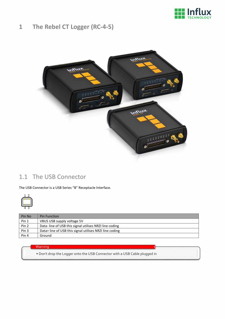
1 The Rebel CT Logger (RC-4-5)
1.1 The USB Connector
The USB Connector is a USB Series “B” Receptacle Interface.
Pin No Pin Function
Pin 1 VBUS USB supply voltage 5V
Pin 2 Data- line of USB this signal utilises NRZI line coding
Pin 3 Data+ line of USB this signal utilises NRZI line coding
Pin 4 Ground
• Don't drop the Logger onto the USB Connector with a USB Cable plugged in
Warning

1.2 The OBD & INST Connector
The OBD&INST connector is a Male 25 pin Standard D Type connector.
Pin No Pin Function
Pin 1 Analog Input 3 - do not apply voltages outside of the -10 to +10V range
Pin 2 Ethernet LAN Receive -
Pin 3 Ethernet LAN Transmit -
Pin 4 Analog Input 1 - do not apply voltages outside of the -10 to +10V range
Pin 5 Wake-Up pin to wake logger from sleep mode (for use see Appendix 1)
Pin 6 CAN Bus 1 (Medium Speed Bus) Low Signal
Pin 7 CAN Bus 0 (High Speed Bus) Low Signal
Pin 8 K-Line (1 wire bus) of ISO 9141
Pin 9 4.5-36V Supply Voltage
Pin 10 +4.5V Instrumentation Supply Voltage, ensure that current draw is not more than 100mA
Pin 11 Digital Input or Output 2 - When used as an input do not apply voltages outside of the 0 to +12V range, when used as an Output ensure that current draw is not more than 100mA. More information on use of this pin can be found in Appendix 2 and 3
Pin 12 Digital Input or Output 0 - When used as an input do not apply voltages outside of the 0 to +12V range, when used as an Output ensure that current draw is not more than 100mA. More information on use of this pin can be found in Appendix 2 and 3
Pin 13 CAN Bus 2 (Instrumentation Bus) Low Signal
Pin 14 Analog Input 2 - - do not apply voltages outside of the -10 to +10V range
Pin 15 Ethernet LAN Transmit +
Pin 16 Ethernet LAN Receive +
Pin 17 Analog Input 0 - - do not apply voltages outside of the -10 to +10V range
Pin 18 Analog Ground
Pin 19 CAN Bus 1 (Medium Speed Bus) High Signal
Pin 20 CAN Bus 0 (High Speed Bus) High Signal
Pin 21 Ground - e.g. to be connected to pin 5 of the OBDII connector
Pin 22 Power Ground - e.g. to be connected to pin 4 of the OBDII connector
Pin 23 Digital Input or Output 3 (can also be uses as a switched power supply +Vd). When used as an input do not apply voltages outside of the 0 to +12V range
Pin 24 Digital Input or Output 1 - When used as an input do not apply voltages outside of the 0 to +12V range, when used as an Output ensure that current draw is not more than 100mA. More information on use of this pin can be found in Appendix 2 and 3
Pin 25 CAN Bus 2 (Instrumentation Bus) High Signal
• Don't short circuit or overload any Digital I/O e.g. If using Digital Input or Output 3 to supply power to power a K-Box or Rebel Dash, do not connect more than 1 K-Box to this output and be careful that no short circuit occurs.
Warning

• Overloading (I > 400mA) of Pin 10 (+4.5V Instrumentation) will result in a drop in the output voltage
Warning
• Each End of the CAN bus must be terminated with a 120ohm resistor accros CAN H and CAN, The Logger has dip switches inside that may be turned on if it is at the end of a CAN bus to allow the bus to be terminated easily
Warning

1.3 The GPS Connector
The Optional GPS connector is a Male SMB connector.
Pin No Pin Function
Pin 1 Radio Frequency Signal Input
Pin 2 Ground
1.4 The GPRS Connector
The Optional GPRS connector is a Male RP-SMA connector.
Pin No Pin Function
Pin 1 Radio Frequency Signal Input
Pin 2 Ground
1.5 The WiFi Connector
The Optional WiFi connector is a Female RP-SMA connector.
Pin No Pin Function
Pin 1 Radio Frequency Signal Input
Pin 2 Ground

1.6 The FlexRay Connector
The Optional FlexRay connector is a Male 15 pin 1.27mm Pitch Micro D connector.
Pin No Pin Function
Pin 1 CAN Bus 4 (Ext 1) Low Signal
Pin 2 CAN Bus 4 (Ext 1) High Signal
Pin 3 CAN Bus 5 (Ext 2) Low Signal
Pin 4 CAN Bus 5 (Ext 2) High Signal
Pin 5 CAN Bus 6 (Ext 3) Low Signal
Pin 6 CAN Bus 6 (Ext 3) High Signal
Pin 7 LIN (Local Interconnect Network) Bus
Pin 8 +Vih Supply Voltage
Pin 9 FlexRay Bus 1 BP Signal
Pin 10 FlexRay Bus 1 BM Signal
Pin 11 FlexRay Bus 2 BP Signal
Pin 12 FlexRay Bus 2 BM Signal
Pin 13 Ground for the FlexRay Buses
Pin 14 Ground for the CAN and LIN Buses
Pin 15 Power Ground
• The connector needs to be tighted properly to make a proper connection and ensure reliable operation.
Warning

1.7 The Analog H-Box Connector
The Optional Analog H-Box connector is a Male 25 pin 1.27mm Pitch Micro D connector.
Pin No Pin Function
Pin 1 Address 2 Signal
Pin 2 Analog Input 0 - do not apply voltages outside of the -20 to +20V range
Pin 3 Analog Input 1 - do not apply voltages outside of the -20 to +20V range
Pin 4 Analog Input 2 - do not apply voltages outside of the -20 to +20V range
Pin 5 Analog Input 3 - do not apply voltages outside of the -20 to +20V range
Pin 6 Analog Input 4 - do not apply voltages outside of the -20 to +20V range
Pin 7 Analog Input 5 - do not apply voltages outside of the -20 to +20V range
Pin 8 Analog Input 6 - do not apply voltages outside of the -20 to +20V range
Pin 9 Analog Input 7 - do not apply voltages outside of the -20 to +20V range
Pin 10 Address 1 Signal
Pin 11 Ground Address Signal Ground
Pin 12 Ground Address Signal Ground
Pin 13 Ground - for the +10.7V power supply
Pin 14 Analog Ground
Pin 15 Analog Ground
Pin 16 Analog Ground
Pin 17 Analog Ground
Pin 18 Analog Ground
Pin 19 Analog Ground
Pin 20 Analog Ground
Pin 21 Analog Ground
Pin 22 Analog Ground
Pin 23 Address 0 Signal
Pin 25 +10.7V
• The connector needs to be tighted properly to make a proper connection and ensure reliable operation.
Warning

2 The Rebel CT Logger (RC3-7)
2.1 The USB Connector
The USB Connector is a USB Series “B” Receptacle Interface.
Pin No Pin Function
Pin 1 VBUS USB supply voltage 5V
Pin 2 Data- line of USB this signal utilises NRZI line coding
Pin 3 Data+ line of USB this signal utilises NRZI line coding
Pin 4 Ground
• Don't drop the Logger onto the USB Connector with a USB Cable plugged in
Warning

2.2 The OBD & INST Connector
The OBD&INST connector is a Male 25 pin Standard D Type connector.
Pin No Pin Function
Pin 1 Analog Ground
Pin 2 Analog Input 3 / Ethernet LAN Receive - when used and an Analog Input do not apply voltages outside of the -10 to +10V range
Pin 3 Analog Input 1 / Ethernet LAN Transmit - when used and an Analog Input do not apply voltages outside of the -10 to +10V range
Pin 4 Analog Ground
Pin 5 Wake-Up pin to wake logger from sleep mode (for use see Appendix 1)
Pin 6 CAN Bus 1 (Medium Speed Bus) Low Signal
Pin 7 CAN Bus 0 (High Speed Bus) Low Signal
Pin 8 K-Line (1 wire bus) of ISO 9141
Pin 9 4.5-36V Supply Voltage
Pin 10 +4.5V Instrumentation Supply Voltage, ensure that current draw is not more than 100mA
Pin 11 Digital Input or Output 2 - When used as an input do not apply voltages outside of the 0 to +12V range, when used as an Output ensure that current draw is not more than 100mA. More information on use of this pin can be found in Appendix 2 and 3
Pin 12 Digital Input or Output 0 - When used as an input do not apply voltages outside of the 0 to +12V range, when used as an Output ensure that current draw is not more than 100mA. More information on use of this pin can be found in Appendix 2 and 3
Pin 13 Ground for the Digital Siganls
Pin 14 Analog Ground
Pin 15 Analog Input 2 / Ethernet LAN Receive + when used and an Analog Input do not apply voltages outside of the -10 to +10V range
Pin 16 Analog Input 0 / Ethernet LAN Transmit - when used and an Analog Input do not apply voltages outside of the -10 to +10V range
Pin 17 Analog Ground
Pin 18 Ground for the Wake Up signal
Pin 19 CAN Bus 1 (Medium Speed Bus) High Signal
Pin 20 CAN Bus 0 (High Speed Bus) High Signal
Pin 21 Ground - e.g. to be connected to pin 5 of the OBDII connector
Pin 22 Power Ground - e.g. to be connected to pin 4 of the OBDII connector
Pin 23 Digital Input or Output 3 - When used as an input do not apply voltages outside of the 0 to +12V range, when used as an Output ensure that current draw is not more than 100mA. More information on use of this pin can be found in Appendix 2 and 3
Pin 24 Digital Input or Output 1 - When used as an input do not apply voltages outside of the 0 to +12V range, when used as an Output ensure that current draw is not more than 100mA. More information on use of this pin can be found in Appendix 2 and 3
Pin 25 Ground for the Digital Signals

• Don't short circuit or overload any Digital I/O e.g. If using Digital Input or Output 3 to supply power to power a K-Box or Rebel Dash, do not connect more than 1 K-Box to this output and be careful that no short circuit occurs.
Warning
• Overloading (I > 400mA) of Pin 10 (+4.5V Instrumentation) will result in a drop in the output voltage
Warning
• Each End of the CAN bus must be terminated with a 120ohm resistor accros CAN H and CAN, The Logger has dip switches inside that may be turned on if it is at the end of a CAN bus to allow the bus to be terminated easily
Warning

2.3 The GPS Connector
The Optional GPS connector is a Male SMB connector.
Pin No Pin Function
Pin 1 Radio Frequency Signal Input
Pin 2 Ground
2.4 The GPRS Connector
The Optional GPRS connector is a Male RP-SMA connector.
Pin No Pin Function
Pin 1 Radio Frequency Signal Input
Pin 2 Ground
2.5 The WiFi Connector
The Optional WiFi connector is a Female RP-SMA connector.
Pin No Pin Function
Pin 1 Radio Frequency Signal Input
Pin 2 Ground

3 The Rebel LT Logger (RC4-5)
3.1 The USB Connector
The USB Connector is a USB Series “B” Receptacle Interface.
Pin No Pin Function
Pin 1 VBUS USB supply voltage 5V
Pin 2 Data- line of USB this signal utilises NRZI line coding
Pin 3 Data+ line of USB this signal utilises NRZI line coding
Pin 4 Ground
• Don't drop the Logger onto the USB Connector with a USB Cable plugged in
Warning
• Each End of the CAN bus must be terminated with a 120ohm resistor accros CAN H and CAN, The Logger has dip switches inside that may be turned on if it is at the end of a CAN bus to allow the bus to be terminated easily
Warning

3.2 The OBD & INST Connector
The OBD&INST connector is a Male 25 pin Standard D Type connector.
Pin No Pin Function
Pin 1 Analog Input 3 - do not apply voltages outside of the -10 to +10V range
Pin 2 Ethernet LAN Receive -
Pin 3 Ethernet LAN Transmit -
Pin 4 Analog Input 1 - do not apply voltages outside of the -10 to +10V range
Pin 5 Wake-Up pin to wake logger from sleep mode (for use see Appendix 1)
Pin 6 CAN Bus 1 (Medium Speed Bus) Low Signal
Pin 7 CAN Bus 0 (High Speed Bus) Low Signal
Pin 8 K-Line (1 wire bus) of ISO 9141
Pin 9 4.5-36V Supply Voltage
Pin 10 +4.5V Instrumentation Supply Voltage, ensure that current draw is not more than 100mA
Pin 11 Digital Input or Output 2 - When used as an input do not apply voltages outside of the 0 to +12V range, when used as an Output ensure that current draw is not more than 100mA. More information on use of this pin can be found in Appendix 2 and 3
Pin 12 Digital Input or Output 0 - When used as an input do not apply voltages outside of the 0 to +12V range, when used as an Output ensure that current draw is not more than 100mA. More information on use of this pin can be found in Appendix 2 and 3
Pin 14 Analog Input 2 - do not apply voltages outside of the -10 to +10V range
Pin 15 Ethernet LAN Transmit +
Pin 16 Ethernet LAN Receive +
Pin 17 Analog Input 0 - do not apply voltages outside of the -10 to +10V range
Pin 18 Analog Ground
Pin 19 CAN Bus 1 (Medium Speed Bus) High Signal
Pin 20 CAN Bus 0 (High Speed Bus) High Signal
Pin 21 Ground
Pin 22 Power Ground
Pin 23 Digital Input or Output 3 (can also be uses as a switched power supply +Vd). When used as an input do not apply voltages outside of the 0 to +12V range
Pin 24 Digital Input or Output 1 - When used as an input do not apply voltages outside of the 0 to +12V range, when used as an Output ensure that current draw is not more than 100mA. More information on use of this pin can be found in Appendix 2 and 3
• Don't short circuit or overload any Digital I/O e.g. If using Digital Input or Output 3 to supply power to power a K-Box or Rebel Dash, do not connect more than 1 K-Box to this output and be careful that no short circuit occurs.
Warning

• Overloading (I > 400mA) of Pin 10 (+4.5V Instrumentation) will result in a drop in the output voltage
Warning
• Each End of the CAN bus must be terminated with a 120ohm resistor accros CAN H and CAN, The Logger has dip switches inside that may be turned on if it is at the end of a CAN bus to allow the bus to be terminated easily
Warning
3.3 The GPS Connector
The Optional GPS connector is a Male SMB connector.
Pin No Pin Function
Pin 1 Radio Frequency Signal Input
Pin 2 Ground
3.4 The GPRS Connector
The Optional GPRS connector is a Male RP-SMA connector.
Pin No Pin Function
Pin 1 Radio Frequency Signal Input
Pin 2 Ground
3.5 The WiFi Connector
The Optional WiFi connector is a Female RP-SMA connector.
Pin No Pin Function
Pin 1 Radio Frequency Signal Input
Pin 2 Ground

4 The Rebel LT Logger (LT 3-3, LT 3-4c)
4.1 The USB Connector
The USB Connector is a USB Series “B” Receptacle Interface.
Pin No Pin Function
Pin 1 VBUS USB supply voltage 5V
Pin 2 Data- line of USB this signal utilises NRZI line coding
Pin 3 Data+ line of USB this signal utilises NRZI line coding
Pin 4 Ground
• Don't drop the Logger onto the USB Connector with a USB Cable plugged in
Warning

4.2 The OBD Connector
The OBD Connector is a Male 25 pin Standard D Type connector.
Pin No Pin Function
Pin 1 Analog Ground
Pin 2 Analog Input 3 - do not apply voltages outside of the -10 to +10V range
Pin 3 Analog Input 1 - do not apply voltages outside of the -10 to +10V range
Pin 4 Analog Ground
Pin 5 Wake-Up pin to wake logger from sleep mode (for use see Appendix 1)
Pin 6 CAN Bus 1 (Medium Speed Bus) Low Signal
Pin 7 CAN Bus 0 (High Speed Bus) Low Signal
Pin 8 K-Line (1 wire bus) of ISO 9141
Pin 9 4.5-36V Supply Voltage Supply Voltage
Pin 10 +4.5V Instrumentation Supply Voltage, ensure that current draw is not more than 100mA
Pin 11 Digital Input or Output 2 - When used as an input do not apply voltages outside of the 0 to +5V range, when used as an Output ensure that current draw is not more than 100mA. More information on use of this pin can be found in Appendix 2 and 3
Pin 12 Digital Input or Output 0 - When used as an input do not apply voltages outside of the 0 to +5V range, when used as an Output ensure that current draw is not more than 100mA. More information on use of this pin can be found in Appendix 2 and 3
Pin 13 Ground for the Digital Signals
Pin 14 Analog Ground
Pin 15 Analog Input 2 - do not apply voltages outside of the -10 to +10V range
Pin 16 Analog Input 0 - do not apply voltages outside of the -10 to +10V range
Pin 17 Analog Ground
Pin 18 Ground for the Wake Up Signal
Pin 19 CAN Bus 1 (Medium Speed Bus) High Signal
Pin 20 CAN Bus 0 (High Speed Bus) High Signal
Pin 21 Ground - e.g. to be connected to pin 5 of the OBDII connector
Pin 22 Power Ground - e.g. to be connected to pin 4 of the OBDII connector
Pin 23 Digital Input or Output 3 - When used as an input do not apply voltages outside of the 0 to +5V range, when used as an Output ensure that current draw is not more than 100mA. More information on use of this pin can be found in Appendix 2 and 3
Pin 24 Digital Input or Output 1 - When used as an input do not apply voltages outside of the 0 to +5V range, when used as an Output ensure that current draw is not more than 100mA. More information on use of this pin can be found in Appendix 2 and 3
Pin 25 Ground for the Digital Signals
• Each End of the CAN bus must be terminated with a 120ohm resistor accros CAN H and CAN, The Logger has dip switches inside that may be turned on if it is at the end of a CAN bus to allow the bus to be terminated easily
Warning

5 The Rebel XT ARM Logger (P3-19, B5-15)
5.1 The USB Connector
The USB Connector is a USB Series “B” Receptacle Interface.
Pin No Pin Function
Pin 1 VBUS USB supply voltage 5V
Pin 2 Data- line of USB this signal utilises NRZI line coding
Pin 3 Data+ line of USB this signal utilises NRZI line coding
Pin 4 Ground
• Don't drop the Logger onto the USB Connector with a USB Cable plugged in
Warning

5.2 The OBD Connector
The OBD&INST connector is a Male 25 pin Standard D Type connector.
Pin No Pin Function
Pin 1 Digital Input 1 - Do not apply voltages outside of the 0 to +12V range
Pin 2 Digital Input 3 - Do not apply voltages outside of the 0 to +12V range
Pin 3 +4.5V Instrumentation Supply Voltage, ensure that current draw is not more than 100mA
Pin 4 Ground for the +4.5V Instrumentation Supply Volatge
Pin 6 CAN Bus 4 (Ext 2) Low Signal
Pin 7 CAN Bus 3 (Ext 1) Low Signal
Pin 8 CAN Bus 2 (Instrumentation Bus) Low Signal
Pin 9 CAN Bus 1 (Medium Speed Bus) Low Signal
Pin 10 CAN Bus 0 (High Speed Bus) Low Signal
Pin 11 Ground - Ground for CAN Bus 2,3 and 5
Pin 12 K-Line (1 wire bus) of ISO 9141
Pin 13 4.5-36V Supply Voltage Supply Voltage
Pin 14 Wake Up and Digital Input 0 - Do not apply voltages outside of the 0 to +12V range.
Pin 15 Digital Input 2 - Do not apply voltages outside of the 0 to +12V range.
Pin 16 Ground for the digital signals
Pin 19 CAN Bus 4 (Ext 2) High Signal
Pin 20 CAN Bus 3 (Ext 1) High Signal
Pin 21 CAN Bus 2 (Instrumentation Bus) High Signal
Pin 22 CAN Bus 1 (Medium Speed Bus) High Signal
Pin 23 CAN Bus 0 (High Speed Bus) High Signal
Pin 24 Ground - - e.g. to be connected to pin 5 of the OBDII connector
Pin 25 Power Ground - e.g. to be connected to pin 4 of the OBDII connector
• Don't short circuit or overload any Digital I/O
Warning
• Overloading (I > 400mA) of Pin 3 (+4.5V Instrumentation) will result in a drop in the output voltage
Warning
• Each End of the CAN bus must be terminated with a 120ohm resistor accros CAN H and CAN, The Logger has dip switches inside that may be turned on if it is at the end of a CAN bus to allow the bus to be terminated easily
Warning

6 The Rebel XT Logger (P3-5, P3-11, P3-17, P3-18c, B5-6, B5-9, B5-12, B5-14c)
6.1 The USB Connector
The USB Connector is a USB Series “B” Receptacle Interface.
Pin No Pin Function
Pin 1 VBUS USB supply voltage 5V
Pin 2 Data- line of USB this signal utilises NRZI line coding
Pin 3 Data+ line of USB this signal utilises NRZI line coding
Pin 4 Ground
• Don't drop the Logger onto the USB Connector with a USB Cable plugged in
Warning

6.2 The OBD Connector
The OBD Connector is a Male 9 pin Standard D Type connector.
Pin No Pin Function
Pin 1 Ground - e.g. to be connected to pin 5 of the OBDII connector (This is Power Ground on XT P3-5 and B5-6 - e.g. to be connected to pin 4 of the OBDII connector)
Pin 2 Power Ground - e.g. to be connected to pin 4 of the OBDII connector
Pin 3 CAN Bus 0 (High Speed Bus) High Signal
Pin 4 K-Line (1 wire bus) of ISO 9141
Pin 5 CAN Bus 0 (High Speed Bus) Low Signal
Pin 6 CAN Bus 1 (Medium Speed Bus) Low Signal
Pin 7 CAN Bus 1 (Medium Speed Bus) High Signal
Pin 8 LIN (Only on XT P3-5, P3-11, B5-6 & B5-9)
Pin 9 4.5-36V Supply Voltage Supply Voltage
• Each End of the CAN bus must be terminated with a 120ohm resistor accros CAN H and CAN, The Logger has dip switches inside that may be turned on if it is at the end of a CAN bus to allow the bus to be terminated easily
Warning

7 The K Box
7.1 The CAN Connectors
(2x DB9 CAN Connectors) The CAN connectors are 1x Male and 1x Female 9 pin Standard D Type connectors.
Pin No Pin Function
Pin 1 Digital Output 4 or +4.5V Instrumentation Supply Voltage, ensure that current draw is not more than 100mA
Pin 2 CAN Bus Low Signal
Pin 3 Ground
Pin 4 Digital Input or Output 1 - When used as an input do not apply voltages outside of the 0 to +12V range, when used as an Output ensure that current draw is not more than 100mA. More information on use of this pin can be found in Appendix 2 and 3
Pin 5 Power Ground
Pin 6 Digital Input or Output 3
Pin 7 CAN Bus High Signal
Pin 8 Digital Input or Output 2 - When used as an input do not apply voltages outside of the 0 to +12V range, when used as an Output ensure that current draw is not more than 100mA. More information on use of this pin can be found in Appendix 2 and 3
Pin 9 4.5-36V Supply Voltage

• Each End of the CAN bus must be terminated with a 120ohm resistor accros CAN H and CAN L.
Warning
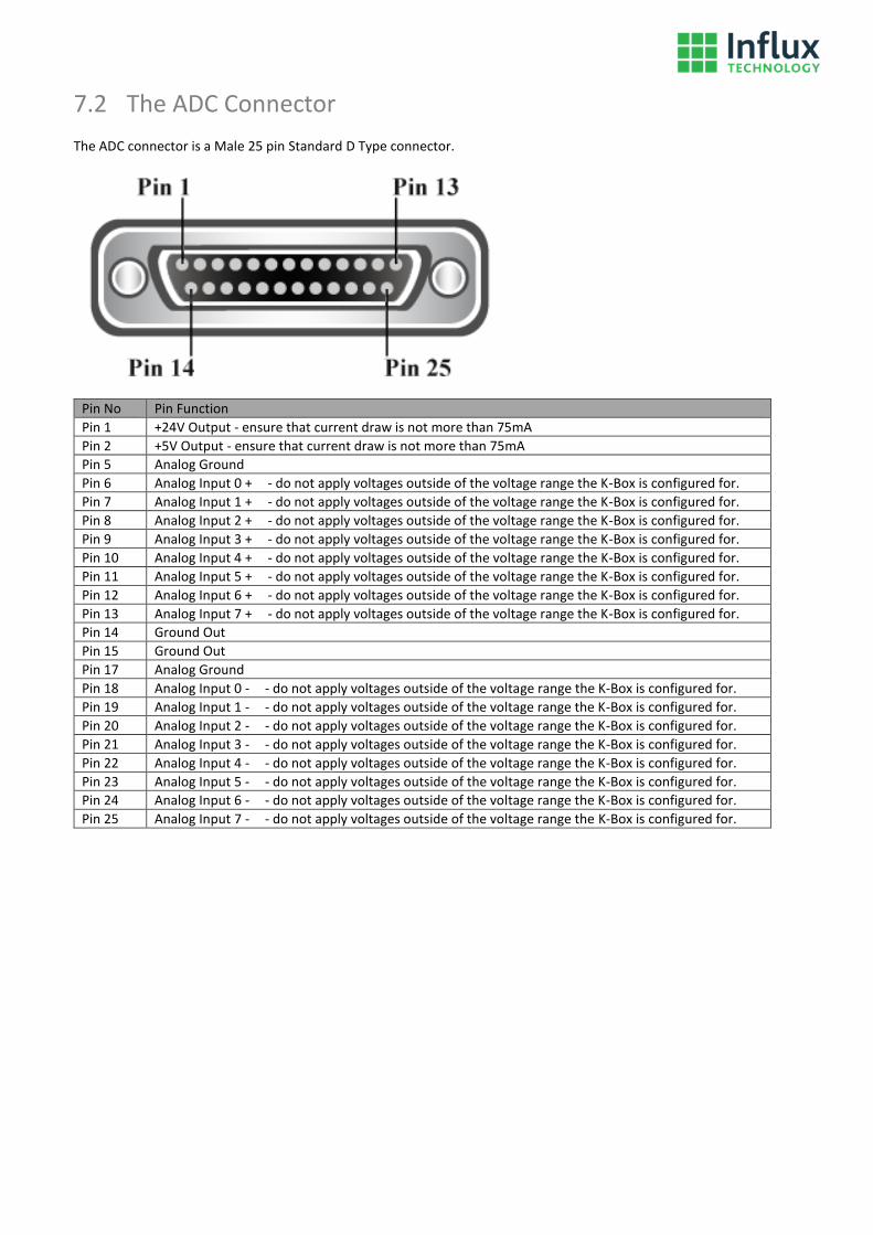
7.2 The ADC Connector
The ADC connector is a Male 25 pin Standard D Type connector.
Pin No Pin Function
Pin 1 +24V Output - ensure that current draw is not more than 75mA
Pin 2 +5V Output - ensure that current draw is not more than 75mA
Pin 5 Analog Ground
Pin 6 Analog Input 0 + - do not apply voltages outside of the voltage range the K-Box is configured for.
Pin 7 Analog Input 1 + - do not apply voltages outside of the voltage range the K-Box is configured for.
Pin 8 Analog Input 2 + - do not apply voltages outside of the voltage range the K-Box is configured for.
Pin 9 Analog Input 3 + - do not apply voltages outside of the voltage range the K-Box is configured for.
Pin 10 Analog Input 4 + - do not apply voltages outside of the voltage range the K-Box is configured for.
Pin 11 Analog Input 5 + - do not apply voltages outside of the voltage range the K-Box is configured for.
Pin 12 Analog Input 6 + - do not apply voltages outside of the voltage range the K-Box is configured for.
Pin 13 Analog Input 7 + - do not apply voltages outside of the voltage range the K-Box is configured for.
Pin 14 Ground Out
Pin 15 Ground Out
Pin 17 Analog Ground
Pin 18 Analog Input 0 - - do not apply voltages outside of the voltage range the K-Box is configured for.
Pin 19 Analog Input 1 - - do not apply voltages outside of the voltage range the K-Box is configured for.
Pin 20 Analog Input 2 - - do not apply voltages outside of the voltage range the K-Box is configured for.
Pin 21 Analog Input 3 - - do not apply voltages outside of the voltage range the K-Box is configured for.
Pin 22 Analog Input 4 - - do not apply voltages outside of the voltage range the K-Box is configured for.
Pin 23 Analog Input 5 - - do not apply voltages outside of the voltage range the K-Box is configured for.
Pin 24 Analog Input 6 - - do not apply voltages outside of the voltage range the K-Box is configured for.
Pin 25 Analog Input 7 - - do not apply voltages outside of the voltage range the K-Box is configured for.

7.3 The Thermocouple Connectors
The Thermocouple connectors on the K-Box are miniature size flat type sockets.
IEC Connector Pin Function
Top + Signal from the Thermocouple
Bottom K Signal from the Thermocouple
The dimensions of the Male Flat Type Miniature Size Thermocouple Plug that you would plug into it is as follows:

8 The Rebel Dash
8.1 The CAN/PWR Connector
The CAN/PWR connector is a Male 9 pin Standard D Type connector.
DB9 Pin Function
Pin 2 CAN Bus Low Signal
Pin 3 Ground (alternatively pin 5 may be used)
Pin 5 Ground (alternatively pin 3 may be used)
Pin 7 CAN Bus High Signal
Pin 9 Power Supply 10-32V
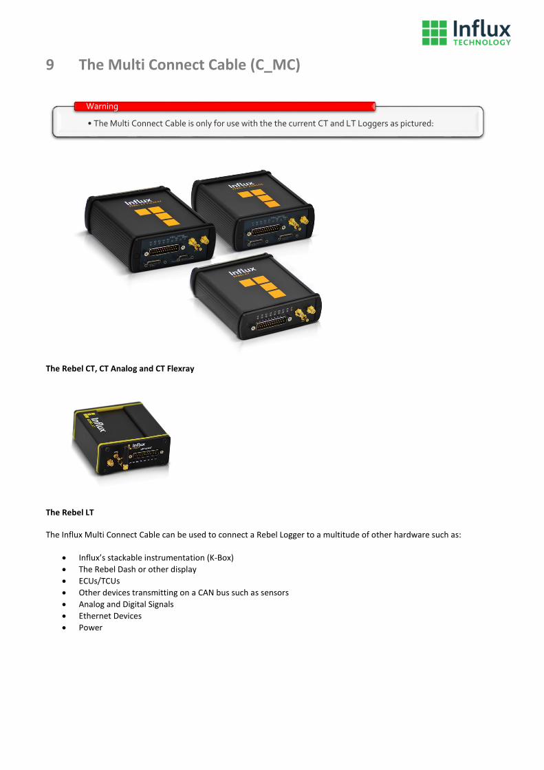
9 The Multi Connect Cable (C_MC)
The Rebel CT, CT Analog and CT Flexray
The Rebel LT The Influx Multi Connect Cable can be used to connect a Rebel Logger to a multitude of other hardware such as:
Influx’s stackable instrumentation (K-Box)
The Rebel Dash or other display
ECUs/TCUs
Other devices transmitting on a CAN bus such as sensors
Analog and Digital Signals
Ethernet Devices
Power
• The Multi Connect Cable is only for use with the the current CT and LT Loggers as pictured:
Warning

The Multi Connect Cable is pictured below:
9.1 The CAN0 / PWR Port
CAN0/PWR (This Connector is used to power the Logger e.g. it could be powered via the diagnostics connector of a vehicle connected to the OBD2 to DB9 Cable) The CAN0/PWR connector is a Male 9 pin Standard D Type connector.
Pin No Pin Function
Pin 1 CAN Bus 1 (Medium Speed Bus) Low Signal
Pin 2 CAN Bus 0 (High Speed Bus) Low Signal
Pin 3 Ground
Pin 4 K-Line (1 wire bus) of ISO 9141
Pin 5 Power Ground
Pin 7 CAN Bus 0 (High Speed Bus) High Signal
Pin 8 CAN Bus 1 (Medium Speed Bus) High Signal
Pin 9 4.5-36V Supply Voltage

9.2 The AUX / CAN1 Port
AUX/CAN1 (The port of the Multi Connect Cable that is normally used with the K-Box and Rebel Dash) The AUX/CAN1 connector is a Female 9 pin Standard D Type connector.
Pin No Pin Function
Pin 2 CAN Bus 1 (Medium Speed Bus) Low Signal
Pin 3 Ground
Pin 5 Ground
Pin 7 CAN Bus 1 (Medium Speed Bus) High Signal
Pin 9 Power Supply Switched
• Don't short circuit or overload Power Supply Switched e.g. do not connect more than 1 K-Box to this output and be careful that no short circuit occurs.
Warning

9.2 The Dig & An Port
Dig & An (This Connector is used to connect Digital and Analog signals to the Logger) The Dig & An connector is a Female 15 pin Standard D Type connector.
Pin No Pin Function
Pin 2 Digital Input or Output 1 - When used as an input do not apply voltages outside of the 0 to +12V range, when used as an Output ensure that current draw is not more than 100mA. More information on use of this pin can be found in Appendix 2 and 3
Pin 3 +4.5V Instrumentation Supply Voltage, ensure that current draw is not more than 100mA
Pin 4 Ground
Pin 6 Analog Ground
Pin 7 Analog Input 1 - do not apply voltages outside of the -10 to +10V range
Pin 8 Analog Input 3 - do not apply voltages outside of the -10 to +10V range
Pin 9 Digital Input or Output 0 - When used as an input do not apply voltages outside of the 0 to +12V range, when used as an Output ensure that current draw is not more than 100mA. More information on use of this pin can be found in Appendix 2 and 3
Pin 10 Digital Input or Output 2 - When used as an input do not apply voltages outside of the 0 to +12V range, when used as an Output ensure that current draw is not more than 100mA. More information on use of this pin can be found in Appendix 2 and 3
Pin 11 Ground
Pin 13 Wake-Up pin to wake logger from sleep mode (for use see Appendix 1)
Pin 14 Analog Input 0 - do not apply voltages outside of the -10 to +10V range
Pin 15 Analog Input 2 - do not apply voltages outside of the -10 to +10V range
• Don't short circuit or overload any Digital I/O e.g. be careful that no short circuit occurs when using an I/O as an output.
Warning
• Don't short circuit or overload Pin 10 (+4.5V Instrumentation)
Warning

9.3 The LAN Port
LAN (Used for connecting CAN2 and Ethernet to the Logger) The LAN connector is a Female 9 pin Standard D Type connector.
Pin No Pin Function
Pin 1 Ethernet LAN Receive -
Pin 2 CAN Bus 2 (Instrumentation Bus) Low Signal
Pin 3 Power Ground
Pin 4 Ethernet LAN Transmit +
Pin 5 Power Ground
Pin 6 Ethernet LAN Receive +
Pin 7 CAN Bus 2 (Instrumentation Bus) High Signal
Pin 8 Ethernet LAN Transmit -
Pin 9 Digital Input or Output 3 (can also be uses as a switched power supply +Vd). When used as an input do not apply voltages outside of the 0 to +12V range
• Don't short circuit or overload Digital Input or Output 3 e.g. if you us it to to supply power to power another device do not overload the power supply and be careful that no short circuit occurs.
Warning

9.4 The OBD & INST Port
OBD&INST (The multi connect cable attaches to the Logger via this connector) The OBD&INST connector is a Female 25 pin Standard D Type connector.
Pin No Pin Function
Pin 1 Analog Input 3 - do not apply voltages outside of the -10 to +10V range
Pin 2 Ethernet LAN Receive -
Pin 3 Ethernet LAN Transmit -
Pin 4 Analog Input 1 - do not apply voltages outside of the -10 to +10V range
Pin 5 Wake-Up pin to wake logger from sleep mode (for use see Appendix 1)
Pin 6 CAN Bus 1 (Medium Speed Bus) Low Signal
Pin 7 CAN Bus 0 (High Speed Bus) Low Signal
Pin 8 K-Line (1 wire bus) of ISO 9141
Pin 9 4.5-36V Supply Voltage
Pin 10 +4.5V Instrumentation Supply Voltage, ensure that current draw is not more than 100mA
Pin 11 Digital Input or Output 2 - When used as an input do not apply voltages outside of the 0 to +12V range, when used as an Output ensure that current draw is not more than 100mA. More information on use of this pin can be found in Appendix 2 and 3
Pin 12 Digital Input or Output 0 - When used as an input do not apply voltages outside of the 0 to +12V range, when used as an Output ensure that current draw is not more than 100mA. More information on use of this pin can be found in Appendix 2 and 3
Pin 13 CAN Bus 2 (Instrumentation Bus) Low Signal
Pin 14 Analog Input 2 - do not apply voltages outside of the -10 to +10V range
Pin 15 Ethernet LAN Transmit +
Pin 16 Ethernet LAN Receive +
Pin 17 Analog Input 0 - do not apply voltages outside of the -10 to +10V range
Pin 18 Analog Ground
Pin 19 CAN Bus 1 (Medium Speed Bus) High Signal
Pin 20 CAN Bus 0 (High Speed Bus) High Signal
Pin 21 Ground
Pin 22 Power Ground
Pin 23 Digital Input or Output 3 (can also be uses as a switced power supply +Vd)
Pin 24 Digital Input or Output 1 - When used as an input do not apply voltages outside of the 0 to +12V range, when used as an Output ensure that current draw is not more than 100mA. More information on use of this pin can be found in Appendix 2 and 3
Pin 25 CAN Bus 2 (Instrumentation Bus) High Signal
• Don't short circuit or overload any Digital I/O e.g. If using Digital Input or Output 3 to supply power to power a K-Box or Rebel Dash, do not connect more than 1 K-Box to this output and be careful that no short circuit occurs.
Warning

• Don't short circuit or overload Pin 10 (+4.5V Instrumentation)
Warning

10 The OBDII to 9 way D Type Cable (C_MC_OBDII_4.5)
The Influx OBD to 9 way D Type Cable can be used to connect power and the Diagnostics CAN bus of a vehicle to the Rebel Dash or a K-Box. It can also be used to connect to the CAN0/PWR port of a Multi Connect Cable to connect power and the Diagnostics CAN bus of a vehicle to a current Rebel CT or LT Logger.
10.1 The 9 way D Type
The 9 way D Type Connector is a Female 9 pin Standard D Type connector.
Pin No Pin Function
Pin 2 CAN Bus 0 (High Speed Bus) Low Signal
Pin 3 Ground
Pin 4 K-Line (1 wire bus) of ISO 9141
Pin 5 Power Ground
Pin 7 CAN Bus 0 (High Speed Bus) High Signal
Pin 9 4.5-36V Supply Voltage

10.2 The OBD Connector
The OBD Connector is a Male 16 pin OBDII connector.
Pin No Pin Function
Pin 4 Power Ground
Pin 5 Ground
Pin 6 CAN Bus 0 (High Speed Bus) High Signal
Pin 7 K-Line (1 wire bus) of ISO 9141
Pin 14 CAN Bus 0 (High Speed Bus) Low Signal
Pin 16 4.5-36V Supply Voltage

11 The OBDII to 9 way D Type Cable (C_MC_OBDII_F_4.5)
The Influx OBDII to 9 way D Type Cable can be used to connect power and the Diagnostics CAN bus of a vehicle to the Rebel Dash or a K-Box. It can also be used to connect to the CAN0/PWR port of a Multi Connect Cable to connect power and the Diagnostics CAN bus of a vehicle to a current Rebel CT or LT Logger.
11.1 The 9 way D Type
The 9 way D Type Connector is a Female 9 pin Standard D Type connector.
Pin No Pin Function
Pin 1 CAN Bus 1 (Medium Speed Bus) Low Signal
Pin 2 CAN Bus 0 (High Speed Bus) Low Signal
Pin 3 Ground
Pin 4 K-Line (1 wire bus) of ISO 9141
Pin 5 Power Ground
Pin 7 CAN Bus 0 (High Speed Bus) High Signal
Pin 8 CAN Bus 1 (Medium Speed Bus) High Signal
Pin 9 4.5-36V Supply Voltage

11.2 The OBDII Connector
The OBDII Connector is a Male 16 pin OBDII connector.
Pin No Pin Function
Pin 3 P CAN Bus 1 (Medium Speed Bus) High Signal
Pin 4 Power Ground
Pin 5 Ground
Pin 6 CAN Bus 0 (High Speed Bus) High Signal
Pin 7 K-Line (1 wire bus) of ISO 9141
Pin 11 CAN Bus 1 (Medium Speed Bus) Low Signal
Pin 14 CAN Bus 0 (High Speed Bus) Low Signal
Pin 16 4.5-36V Supply Voltage
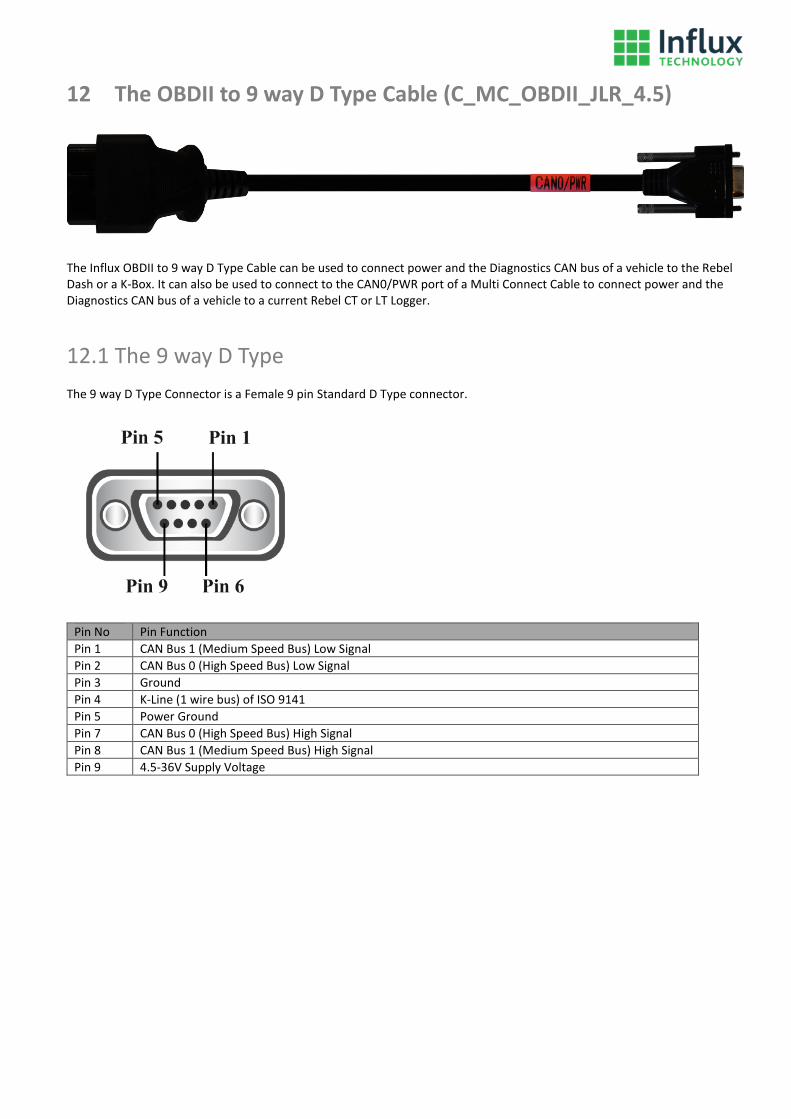
12 The OBDII to 9 way D Type Cable (C_MC_OBDII_JLR_4.5)
The Influx OBDII to 9 way D Type Cable can be used to connect power and the Diagnostics CAN bus of a vehicle to the Rebel Dash or a K-Box. It can also be used to connect to the CAN0/PWR port of a Multi Connect Cable to connect power and the Diagnostics CAN bus of a vehicle to a current Rebel CT or LT Logger.
12.1 The 9 way D Type
The 9 way D Type Connector is a Female 9 pin Standard D Type connector.
Pin No Pin Function
Pin 1 CAN Bus 1 (Medium Speed Bus) Low Signal
Pin 2 CAN Bus 0 (High Speed Bus) Low Signal
Pin 3 Ground
Pin 4 K-Line (1 wire bus) of ISO 9141
Pin 5 Power Ground
Pin 7 CAN Bus 0 (High Speed Bus) High Signal
Pin 8 CAN Bus 1 (Medium Speed Bus) High Signal
Pin 9 4.5-36V Supply Voltage

12.2 The OBDII Connector
The OBDII Connector is a Male 16 pin OBDII connector.
Pin No Pin Function
Pin 2 P CAN Bus 1 (Medium Speed Bus) High Signal
Pin 4 Power Ground
Pin 5 Ground
Pin 6 CAN Bus 0 (High Speed Bus) High Signal
Pin 7 K-Line (1 wire bus) of ISO 9141
Pin 10 CAN Bus 1 (Medium Speed Bus) Low Signal
Pin 14 CAN Bus 0 (High Speed Bus) Low Signal
Pin 16 4.5-36V Supply Voltage

13 The OBDII Type B to 9 way D Type Cable
The Influx OBDII Type B to 9 way D Type Cable can be used to connect power and the Diagnostics CAN bus of a vehicle to the Rebel Dash or a K-Box. It can also be used to connect to the CAN0/PWR port of a Multi Connect Cable to connect power and the Diagnostics CAN bus of a vehicle to a current Rebel CT or LT Logger. Type B connectors may be plugged into both 12V and 24V Vehicles.
13.1 The 9 way D Type
The 9 way D Type Connector is a Female 9 pin Standard D Type connector.
Pin No Pin Function
Pin 2 CAN Bus 0 (High Speed Bus) Low Signal
Pin 3 Ground
Pin 4 K-Line (1 wire bus) of ISO 9141
Pin 5 Power Ground
Pin 7 CAN Bus 0 (High Speed Bus) High Signal
Pin 9 4.5-36V Supply Voltage

13.2 The OBDII Connector
The OBDII Connector is a Male 16 pin OBDII (Type B) connector.
Pin No Pin Function
Pin 4 Power Ground
Pin 5 Ground
Pin 6 CAN Bus 0 (High Speed Bus) High Signal
Pin 7 K-Line (1 wire bus) of ISO 9141
Pin 14 CAN Bus 0 (High Speed Bus) Low Signal
Pin 16 4.5-36V Supply Voltage

14 The OBDII to 25 way D Type Cable
The Influx OBDII to 25 way D Type Cable can be used to connect power and the Diagnostics CAN bus of a vehicle to the current Rebel CT or LT Loggers directly.
14.1 The 25 way D Type
The 25 way D Type Connector is a Female 25 pin Standard D Type connector.
Pin No Pin Function
Pin 6 CAN Bus 1 (Medium Speed Bus) Low Signal
Pin 7 CAN Bus 0 (High Speed Bus) Low Signal
Pin 8 K-Line (1 wire bus) of ISO 9141
Pin 9 4.5-36V Supply Voltage
Pin 19 CAN Bus 1 (Medium Speed Bus) High Signal
Pin 20 CAN Bus 0 (High Speed Bus) High Signal
Pin 21 Ground
Pin 22 Power Ground

14.2 The OBDII Connector
The OBDII Connector is a Male 16 pin OBDII connector.
Pin No Pin Function
Pin 3 CAN Bus 1 (Medium Speed Bus) High Signal
Pin 4 Power Ground
Pin 5 Ground
Pin 6 CAN Bus 0 (High Speed Bus) High Signal
Pin 7 K-Line (1 wire bus) of ISO 9141
Pin 11 CAN Bus 1 (Medium Speed Bus) Low Signal
Pin 14 CAN Bus 0 (High Speed Bus) Low Signal
Pin 16 4.5-36V Supply Voltage

15 The Flexray Breakout Cable (C_MCCF_1-2)
The Influx Flexray Breakout Cable can be used to connect any or all of the following buses to the Rebel CT Flexray:
Flexray 1
Flexray 2
CAN 2
CAN 3
CAN 4
LIN
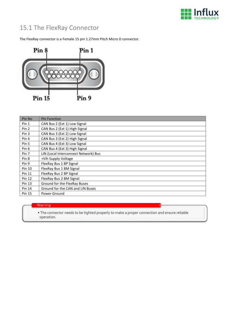
15.1 The FlexRay Connector
The FlexRay connector is a Female 15 pin 1.27mm Pitch Micro D connector.
Pin No Pin Function
Pin 1 CAN Bus 2 (Ext 1) Low Signal
Pin 2 CAN Bus 2 (Ext 1) High Signal
Pin 3 CAN Bus 3 (Ext 2) Low Signal
Pin 4 CAN Bus 3 (Ext 2) High Signal
Pin 5 CAN Bus 4 (Ext 3) Low Signal
Pin 6 CAN Bus 4 (Ext 3) High Signal
Pin 7 LIN (Local Interconnect Network) Bus
Pin 8 +Vih Supply Voltage
Pin 9 FlexRay Bus 1 BP Signal
Pin 10 FlexRay Bus 1 BM Signal
Pin 11 FlexRay Bus 2 BP Signal
Pin 12 FlexRay Bus 2 BM Signal
Pin 13 Ground for the FlexRay Buses
Pin 14 Ground for the CAN and LIN Buses
Pin 15 Power Ground
• The connector needs to be tighted properly to make a proper connection and ensure reliable operation.
Warning

15.2 The FR-1 Connector
The FR-1 connector is a Male 9 pin Standard D Type connector.
Pin No Pin Function
Pin 2 FlexRay Bus 1 BM Signal
Pin 3 Ground for the FlexRay Buses
Pin 5 Power Ground
Pin 7 FlexRay Bus 1 BP Signal
15.3 The FR-2 Connector
The FR-2 connector is a Male 9 pin Standard D Type connector.
Pin No Pin Function
Pin 2 FlexRay Bus 2 BM Signal
Pin 3 Ground for the FlexRay Buses
Pin 5 Power Ground
Pin 7 FlexRay Bus 2 BP Signal

15.4 The CAN-2 & LIN Connector
The CAN-2 & LIN Connector is a Female 9 pin Standard D Type connector.
Pin No Pin Function
Pin 2 CAN Bus 2 (Ext 1) Low Signal
Pin 3 Ground for the CAN and LIN Buses
Pin 4 LIN (Local Interconnect Network) Bus
Pin 5 Power Ground
Pin 7 CAN Bus 2 (Ext 1) High Signal
15.5 The CAN-3 Connector
The CAN-3 Connector is a Female 9 pin Standard D Type connector.
Pin No Pin Function
Pin 2 CAN Bus 3 (Ext 2) Low Signal
Pin 3 Ground for the CAN and LIN Buses
Pin 5 Power Ground
Pin 7 CAN Bus 3 (Ext 2) High Signal

15.6 The CAN-4 Connector
The CAN-4 Connector is a Female 9 pin Standard D Type connector.
Pin No Pin Function
Pin 2 CAN Bus 4 (Ext 3) Low Signal
Pin 3 Ground for the CAN and LIN Buses
Pin 5 Power Ground
Pin 7 CAN Bus 4 (Ext 3) High Signal

Appendix 1 The Wake Up Pin
The Loggers Wake up pin is held high and the logger can be woken up by switching the pin to ground in one of the three ways shown below, if the pin is switched to ground for longer than 20ms it will wake from sleep mode.

Appendix 2 Digital Input function
The Digital Input Output Pins will consider voltages below 1.6V to be low and above 2.5V to be high, examples of how you could utilise the I/O pins if configured as Inputs are shown below.

Appendix 3 Digital Output function
The Digital Input Output Pins will consider voltages below 1.6V to be low and above 2.5V to be high, examples of how you could utilise the I/O pins if configured as Inputs are shown below.