table of contents - cdn.intrepidcs.net · hardware settings ... neovi and valuecan devices include...
TRANSCRIPT

Table of Contents
1Overview ........................................................................................................................................................................................................................................................................................................................2Getting Started ..........................................................................................................................................................................................................................................................................................................3Hardware Basics .....................................................................................................................................................................................................................................................................................................4Connecting to Your PC ...................................................................................................................................................................................................................................................................................5Connecting to Your Vehicle ..........................................................................................................................................................................................................................................................................6ValueCAN Connection ...........................................................................................................................................................................................................................................................................8neoVI Blue Connection .........................................................................................................................................................................................................................................................................
10neoVI FIRE / RED Connection .........................................................................................................................................................................................................................................................12neoVI Yellow .........................................................................................................................................................................................................................................................................................14Application Software ....................................................................................................................................................................................................................................................................................15Hardware Configuration ..............................................................................................................................................................................................................................................................................17Firmware Updates ...............................................................................................................................................................................................................................................................................18In-vehicle Networks ...........................................................................................................................................................................................................................................................................................19CAN networks .................................................................................................................................................................................................................................................................................................20High Speed CAN .................................................................................................................................................................................................................................................................................21Medium Speed CAN ...........................................................................................................................................................................................................................................................................22Single Wire CAN .................................................................................................................................................................................................................................................................................23Low Speed Fault Tolerant CAN ........................................................................................................................................................................................................................................................24CAN Baud Rates and Bit Timing .....................................................................................................................................................................................................................................................25Bit Timing Calculator ...................................................................................................................................................................................................................................................................26Terminating a Dual Wire CAN Network .........................................................................................................................................................................................................................................27Terminating a Low Speed Fault Tolerant CAN Network ............................................................................................................................................................................................................28J1850 VPW (Class 2) ..................................................................................................................................................................................................................................................................................29J1850 PWM (Ford PWM) ..........................................................................................................................................................................................................................................................................31J1708 ..................................................................................................................................................................................................................................................................................................................32UART/ISO9141/KW2K/LIN .......................................................................................................................................................................................................................................................................34UART Timing ........................................................................................................................................................................................................................................................................................35Initialization Waveforms ....................................................................................................................................................................................................................................................................36Error Checking .....................................................................................................................................................................................................................................................................................37Local Interconnect Network (LIN) ...................................................................................................................................................................................................................................................38LIN Slave Table ...........................................................................................................................................................................................................................................................................39Hardware Features ............................................................................................................................................................................................................................................................................................

40neoVI Blue ........................................................................................................................................................................................................................................................................................................41Theory of Operation ............................................................................................................................................................................................................................................................................44LED .........................................................................................................................................................................................................................................................................................................45General Purpose IO ............................................................................................................................................................................................................................................................................47DAQ Pacer Clock ................................................................................................................................................................................................................................................................................48Specifications .......................................................................................................................................................................................................................................................................................50Hardware Settings ...............................................................................................................................................................................................................................................................................51neoVI FIRE / RED .........................................................................................................................................................................................................................................................................................52General Purpose IO ............................................................................................................................................................................................................................................................................54Specifications .......................................................................................................................................................................................................................................................................................56Hardware Settings ...............................................................................................................................................................................................................................................................................57LED Blinking .........................................................................................................................................................................................................................................................................................59neoVI Yellow ....................................................................................................................................................................................................................................................................................................60General Purpose IO ............................................................................................................................................................................................................................................................................62Specifications .......................................................................................................................................................................................................................................................................................63Hardware Settings ...............................................................................................................................................................................................................................................................................57LED Blinking .........................................................................................................................................................................................................................................................................................64ValueCAN 3 .....................................................................................................................................................................................................................................................................................................65General Purpose IO ............................................................................................................................................................................................................................................................................66Specifications .......................................................................................................................................................................................................................................................................................67Related Info ..............................................................................................................................................................................................................................................................................................................68SAE OBD Book ..............................................................................................................................................................................................................................................................................................69Internet Resources ........................................................................................................................................................................................................................................................................................70Glossary ............................................................................................................................................................................................................................................................................................................71Contact .........................................................................................................................................................................................................................................................................................................................
Hardware Overview Main
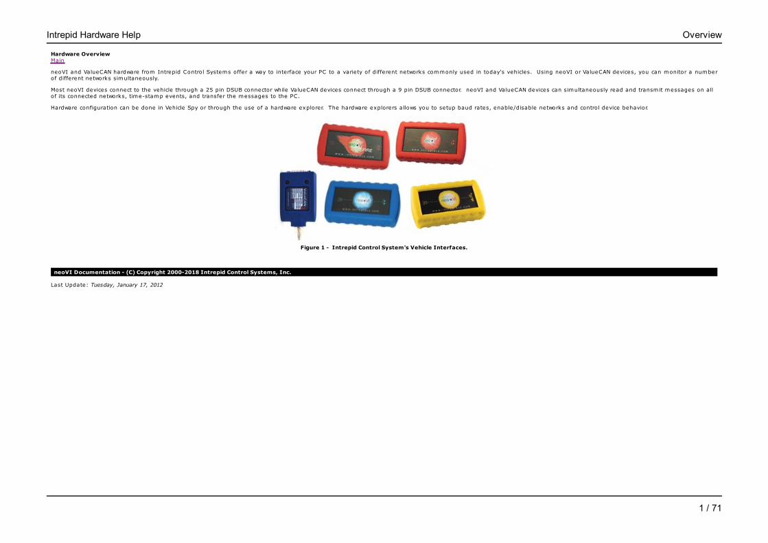
neoVI and ValueCAN hardware from Intrepid Control Systems offer a way to interface your PC to a variety of different networks commonly used in today's vehicles. Using neoVI or ValueCAN devices, you can monitor a numberof different networks simultaneously.
Most neoVI devices connect to the vehicle through a 25 pin DSUB connector while ValueCAN devices connect through a 9 pin DSUB connector. neoVI and ValueCAN devices can simultaneously read and transmit messages on allof its connected networks, time-stamp events, and transfer the messages to the PC.
Hardware configuration can be done in Vehicle Spy or through the use of a hardware explorer. The hardware explorers allows you to setup baud rates, enable/disable networks and control device behavior.
Figure 1 - Intrepid Control System's Vehicle Interfaces.
neoVI Documentation - (C) Copyright 2000-2018 Intrepid Control Systems, Inc.
Last Update: Tuesday, January 17, 2012
Intrepid Hardware Help Overview
1 / 71
Getting StartedMain
Installing Software and Configuration Tools
The first step to using the API, is installing the needed drivers and dlls. This can be done in a few different ways. Installing Vehicle Spy 3 (full and free version) or the API install kit foundon the CD that shipped with the hardware will take care of this step. Software can also be found on support page of Intrepid Control Systems Website.
From the CD that shipped with the unit, run the icsAutoPlay.exe from the root of the disc (if it does not start automatically). This will give you the option of installing Vehicle Spy 3 or theAPI install kit. From the Website, the following links will have the latest software.
-Vehicle Spy 3 Trial includes everything in the API install kit and has Vehicle Spy 3 Trial.-API install kit for RP1210, J2534, and Intrepid Controls Systems' API.
Installing the neoVI device on USB
Next, verify that you have the following minimum system requirements:
One free USB portWindows XP (SP3), Vista, 7, 8, 8.1, or 10 (Windows RT is not supported)
If Vehicle Spy 3 is installed, the hardware drivers are also installed. When a device is plugged in, Windows should recognize it and finish the driver install.
Installation Support
If you have any problems installing neoVI or ValueCAN devices, please call Intrepid Control Systems, Inc. at 810-731-7950.
Vehicle Connections
neoVI and ValueCAN devices include a copy of their pinouts on the device. Also, please see the neoVI user documentation.
Additional Information
Please review the following sources for more information on the neoVI vehicle interface.
Description Location
neoVI Online Documentation Installed with neoVI Explorer
neoVI Website http://www.intrepidcs.com/neovi/
Vehicle Spy 3 website http://www.intrepidcs.com/vspy/
neoVI Documentation - (C) Copyright 2000-2018 Intrepid Control Systems, Inc.
Last Update: Tuesday, May 31, 2016
Intrepid Hardware Help Getting Started
2 / 71

neoVI BasicsMain
Applies to neoVI Blue, neoVI Red, neoVI FIRE, neoVI Yellow, and ValueCAN
To use neoVI or ValueCAN devices the following steps are needed:
1) connect to your PC2) Connect to your vehicle or device 3) setup the device4) use application software to do your task.
neoVI Documentation - (C) Copyright 2000-2018 Intrepid Control Systems, Inc.
Last Update: Thursday, July 09, 2009
Intrepid Hardware Help Hardware Basics
3 / 71
Connecting To Your PC Main
Applies to neoVI Blue, neoVI Red, neoVI FIRE, neoVI Yellow, and ValueCAN
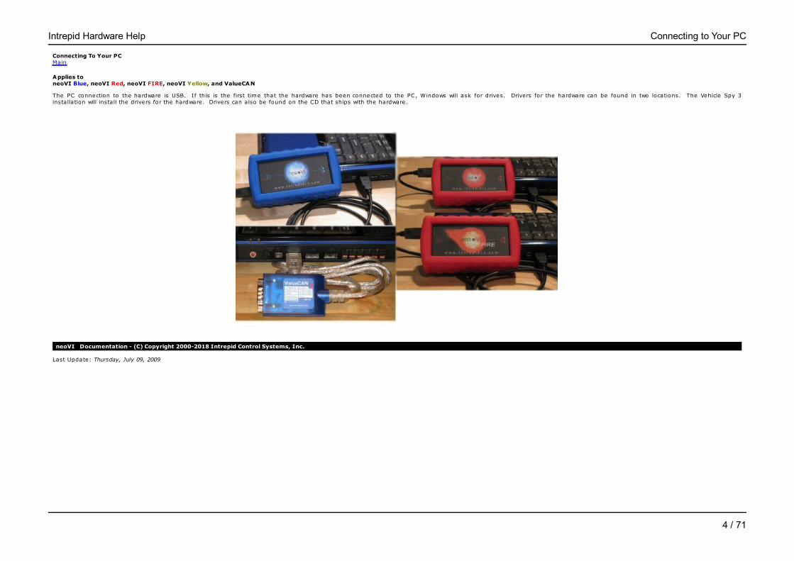
The PC connection to the hardware is USB. If this is the first time that the hardware has been connected to the PC, Windows will ask for drives. Drivers for the hardware can be found in two locations. The Vehicle Spy 3installation will install the drivers for the hardware. Drivers can also be found on the CD that ships with the hardware.
neoVI Documentation - (C) Copyright 2000-2018 Intrepid Control Systems, Inc.
Last Update: Thursday, July 09, 2009
Intrepid Hardware Help Connecting to Your PC
4 / 71
Vehicle Connector - OBD Pin-outMain
Applies to neoVI Blue, neoVI Red, neoVI FIRE, neoVI Yellow, and ValueCAN
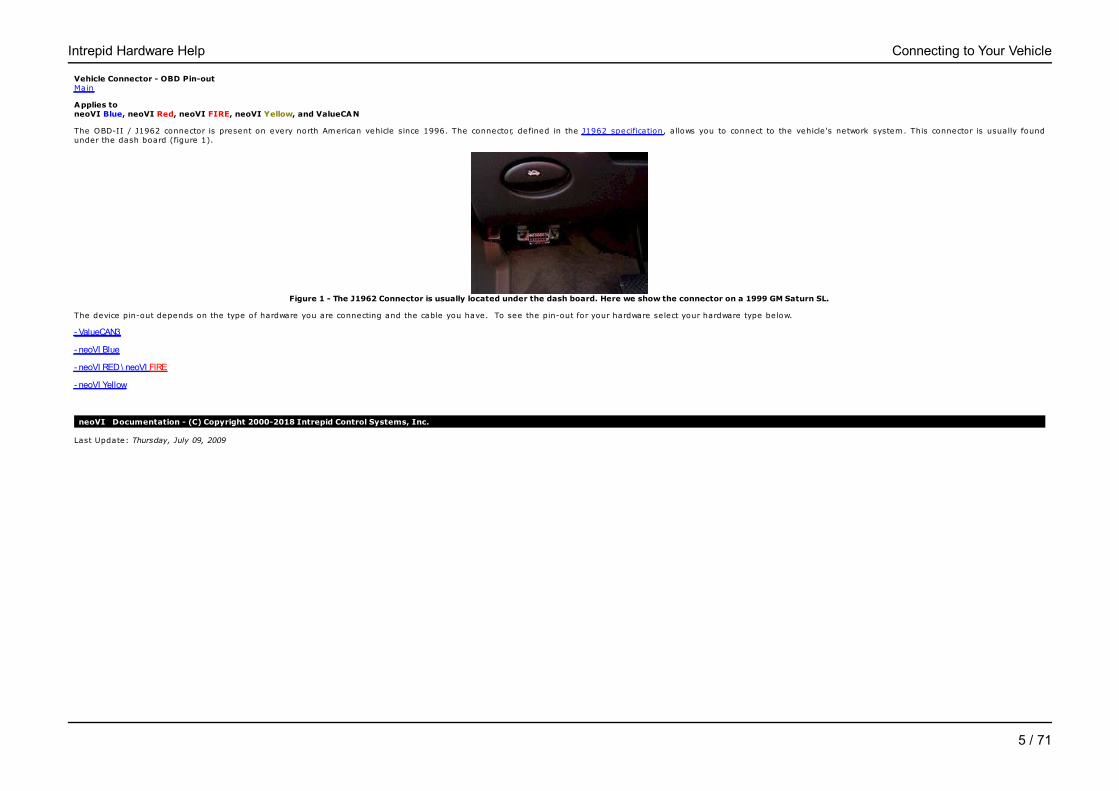
The OBD-II / J1962 connector is present on every north American vehicle since 1996. The connector, defined in the J1962 specification, allows you to connect to the vehicle 's network system. This connector is usually foundunder the dash board (figure 1).
Figure 1 - The J1962 Connector is usually located under the dash board. Here we show the connector on a 1999 GM Saturn SL.
The device pin-out depends on the type of hardware you are connecting and the cable you have. To see the pin-out for your hardware select your hardware type below.
- ValueCAN3
- neoVI Blue
- neoVI RED \ neoVI FIRE
- neoVI Yellow
neoVI Documentation - (C) Copyright 2000-2018 Intrepid Control Systems, Inc.
Last Update: Thursday, July 09, 2009
Intrepid Hardware Help Connecting to Your Vehicle
5 / 71
ValueCAN 3 Vehicle Side ConnectionsMain
Applies to ValueCAN
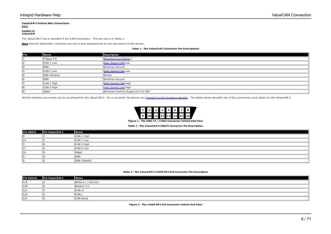
The ValueCAN 3 has a standard 9 pin CAN Connection. This pin-out is in Table 1.
Note that the ValueCAN 3 connector pin-out is also diagrammed on the top sticker of the device.
Table 1 - The ValueCAN 3 Connector Pin Descriptions
Pin Name Description
1 Trigger Pin Miscellaneous Signal 1
2 CAN 1 Low High Speed CAN Low
3 GND Electrical Ground
4 CAN 2 Low High Speed CAN Low
5 GND (Shie ld) Shie ld
6 GND Electrical Ground
7 CAN 1 High High Speed CAN High
8 CAN 2 High High Speed CAN High
9 VBatt Electrical Positive Supply 6.5-40 VDC
Vehicle interface connectors can be purchased for the ValueCAN 3. For a complete list please see Intrepid Control Systems website. The tables below describe two of the commonly used cables for the ValueCAN 3.
Figure 1 - The OBD-II / J1962 Connector Vehicle End View
Table 2 - The ValueCAN 3 OBDII Connector Pin Description
Pin OBDII Pin ValueCAN 3 Name
6 7 CAN 1 High
14 2 CAN 1 Low
3 8 CAN 2 High
11 4 CAN 2 Low
16 9 VBatt
5 3 GND
4 5 GND (Shie ld)
Table 3 - The ValueCAN 3 J1939-RP1210 Connector Pin Description
Pin Vehicle Pin ValueCAN 3 Name
1/A 3 Battery (-) Ground
2/B 9 Battery (+)
3/C 7 CAN_H
4/D 2 CAN L
5/E 5 CAN Sheld
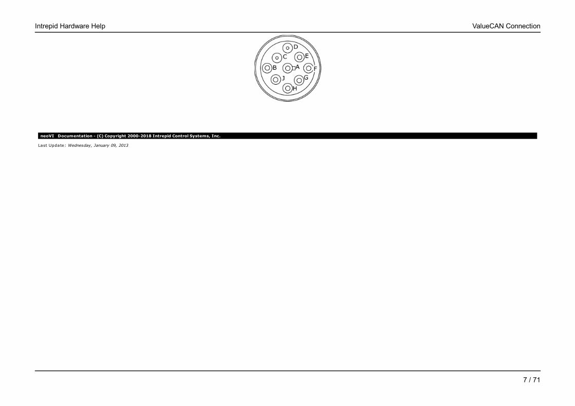
Figure 2 - The J1939-RP1210 Connector Vehicle End View
Intrepid Hardware Help ValueCAN Connection
6 / 71
neoVI Documentation - (C) Copyright 2000-2018 Intrepid Control Systems, Inc.
Last Update: Wednesday, January 09, 2013
Intrepid Hardware Help ValueCAN Connection
7 / 71

neoVI Blue Vehicle Side ConnectionsMain
Applies to neoVI Blue
You can connect neoVI to the Vehicle via the 25 pin D-Sub connector. All of the Vehicle networks and power for the neoVI device itself come from this connector. A listing of the pins of this connector is provided in Table 1 below.
Note that the neoVI connector pin-out is also diagrammed on the bottom of the neoVI device.
Table 1 - The neoVI Connector Pin Descriptions
Pin Name Description
1 SW CAN Single Wire CAN
2 J1850 VPW J1850 VPW (Class 2)
3 LSFT CAN H Low Speed Fault Tolerant CAN High
4 LSFT CAN L Low Speed Fault Tolerant CAN Low
5 J1850 PWM L J1850 PWM (Ford SCP) Low
6 J1850 PWM H J1850 PWM (Ford SCP) High
7 ISO L UART/ISO9141/Keyword Line "L"
8 ISO K UART/ISO9141/Keyword Bi-directional Line "K"
9 MISC 3 Miscellaneous Signal 3
10 MISC 4 Miscellaneous Signal 4
11 MISC 5 Miscellaneous Signal 5
12 MISC 6 Miscellaneous Signal 6
13 PWR GND Electrical Ground
14 HS CAN H High Speed CAN High
15 HS CAN L High Speed CAN Low
16 MS CAN H Medium Speed CAN High
17 MS CAN L Medium Speed CAN Low
18 LIN LIN
19 J1708 H J1708 High
20 J1708 L J1708 Low
21 MISC 1 Miscellaneous Signal 1
22 MISC 2 Miscellaneous Signal 2
23 SCI Tx Not Used
24 SCI Rx Not Used
25 VBATT Electrical Positive Supply 7-25 VDC
Figure 2 - The OBD-II / J1962 Connector Vehicle End View
Table 2 - OBD-II Pins and their corresponding neoVI signal
J1962 Pin J1962 Pin Description neoVI Connection neoVI Pin
1 Discretionary* (GMLAN SW CAN Line) SW CAN 1
2 + line of SAE J1850 J1850 VPW or J1850 PWM H 2 or 6
3 Discretionary* (GMLAN MS CAN H) MS CAN H 16
4 Chassis Ground Do not use for neoVI. 5 Signal Ground PWR GND 13
Intrepid Hardware Help neoVI Blue Connection
8 / 71
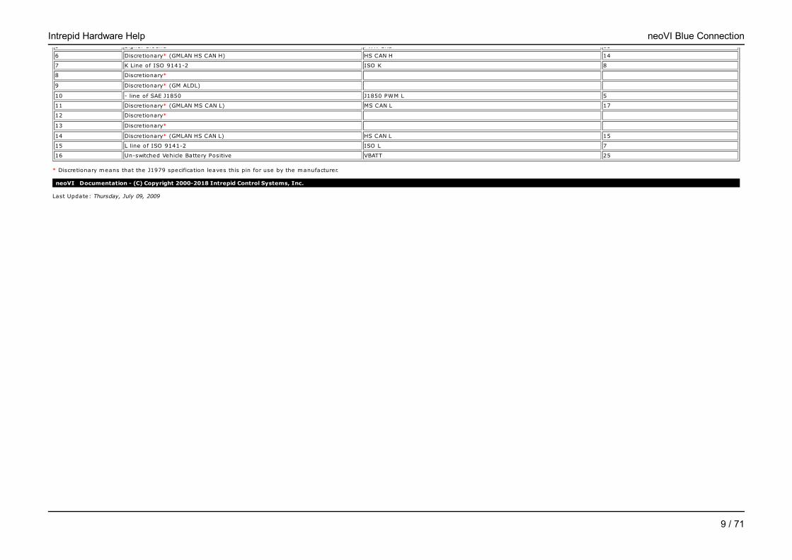
5 Signal Ground PWR GND 13
6 Discretionary* (GMLAN HS CAN H) HS CAN H 14
7 K Line of ISO 9141-2 ISO K 8
8 Discretionary* 9 Discretionary* (GM ALDL) 10 - line of SAE J1850 J1850 PWM L 5
11 Discretionary* (GMLAN MS CAN L) MS CAN L 17
12 Discretionary* 13 Discretionary* 14 Discretionary* (GMLAN HS CAN L) HS CAN L 15
15 L line of ISO 9141-2 ISO L 7
16 Un-switched Vehicle Battery Positive VBATT 25
* Discretionary means that the J1979 specification leaves this pin for use by the manufacturer.
neoVI Documentation - (C) Copyright 2000-2018 Intrepid Control Systems, Inc.
Last Update: Thursday, July 09, 2009
Intrepid Hardware Help neoVI Blue Connection
9 / 71

neoVI FIRE and neoVI RED - Vehicle Side ConnectionsMain
Applies to neoVI Red, and neoVI FIRE
You can connect neoVI to the Vehicle via the 25 pin D-Sub connector. Most of the Vehicle networks and power for the neoVI device itself come from this connector. A listing of the pins of this connector is provided in Table 1below. Additional connections are found on the 9 pin D-Sub connector. A listing of the pins of this connector is provided in Table 2 below
Note that the neoVI connector pin-out is also diagrammed on the bottom of the neoVI device.
Table 2 - NeoVI FIRE and RED 25 pin Connector Pin Descriptions
Pin Name Description
1 SW CAN Single Wire CAN
2 J1850 VPW J1850 VPW (Class 2)
3 LSFT CAN H Low Speed Fault Tolerant CAN High
4 LSFT CAN L Low Speed Fault Tolerant CAN Low
5 MS CAN H Medium Speed CAN High
6 MS CAN L Medium Speed CAN Low
7 ISO L UART/ISO9141/Keyword Line "L"
8 ISO K/LIN 1 UART/ISO9141/Keyword Bi-directional Line "K"
9 DBG CLK Not Used
10 MISC 1 Miscellaneous Signal 1
11 MISC 2 Miscellaneous Signal 2
12 DBG Data Not Used
13 PWR GND Electrical Ground
14 HS CAN H High Speed CAN High
15 HS CAN L High Speed CAN Low
16 HS CAN 2 H High Speed CAN 2 High
17 HS CAN 2 L High Speed CAN 2 Low
18 MISC 4 Miscellaneous Signal 4
19 HS CAN 3 H High Speed CAN 3 High
20 HS CAN 3 L High Speed CAN 3 Low
21 TSYNC CLK H / CGI H CGI High
22 TSYNC CLK L / CGI L CGI Low
23 MISC 3 Miscellaneous Signal 3
24 DBG RESET Not Used
25 VBATT Electrical Positive Supply 6-27 VDC
Table 2 - NeoVI FIRE and RED 9 pin Connector Pin Descriptions
Pin Name Description
1 LIN 1 LIN 1
2 LIN 2 LIN 2
3 LIN 3 LIN 3
4 LIN 4 LIN 4
5 GND Ground Reference
6 MISC 5 Miscellaneous Signal 5
7 MISC 6 Miscellaneous Signal 6
8 NC No Connect
9 VBatt Out No Connect
Intrepid Hardware Help neoVI FIRE / RED Connection
10 / 71
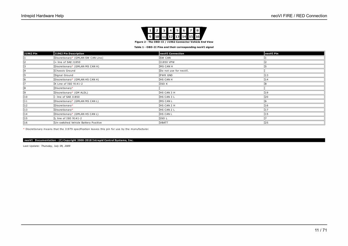
Figure 2 - The OBD-II / J1962 Connector Vehicle End View
Table 1 - OBD-II Pins and their corresponding neoVI signal
J1962 Pin J1962 Pin Description neoVI Connection neoVI Pin
1 Discretionary* (GMLAN SW CAN Line) SW CAN 1
2 + line of SAE J1850 J1850 VPW 2
3 Discretionary* (GMLAN MS CAN H) MS CAN H 5
4 Chassis Ground Do not use for neoVI. 5 Signal Ground PWR GND 13
6 Discretionary* (GMLAN HS CAN H) HS CAN H 14
7 K Line of ISO 9141-2 ISO K 8
8 Discretionary* 9 Discretionary* (GM ALDL) HS CAN 3 H 19
10 - line of SAE J1850 HS CAN 3 L 20
11 Discretionary* (GMLAN MS CAN L) MS CAN L 6
12 Discretionary* HS CAN 2 H 16
13 Discretionary* HS CAN 2 L 17
14 Discretionary* (GMLAN HS CAN L) HS CAN L 15
15 L line of ISO 9141-2 ISO L 7
16 Un-switched Vehicle Battery Positive VBATT 25
* Discretionary means that the J1979 specification leaves this pin for use by the manufacturer.
neoVI Documentation - (C) Copyright 2000-2018 Intrepid Control Systems, Inc.
Last Update: Thursday, July 09, 2009
Intrepid Hardware Help neoVI FIRE / RED Connection
11 / 71
neoVI Yellow Vehicle Side ConnectionsMain
Applies to neoVI Yellow
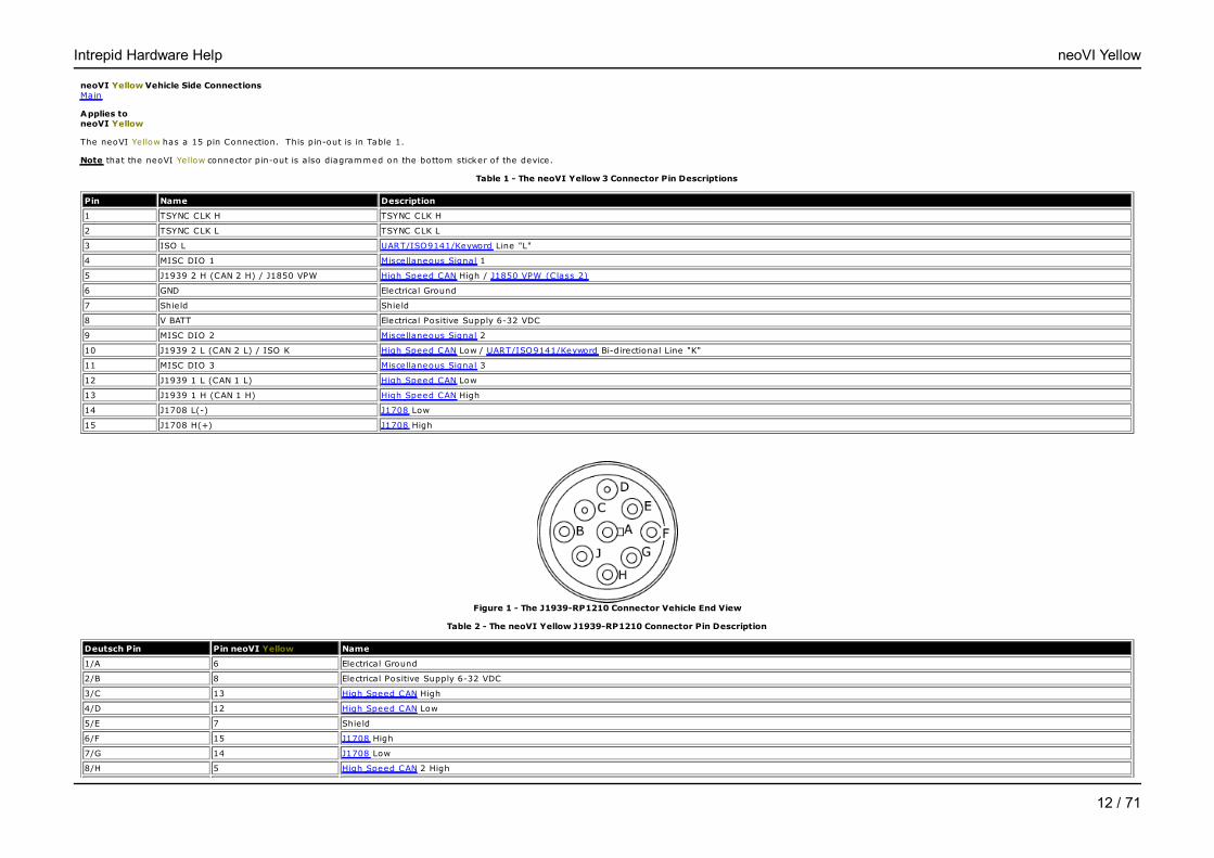
The neoVI Yellow has a 15 pin Connection. This pin-out is in Table 1.
Note that the neoVI Yellow connector pin-out is also diagrammed on the bottom sticker of the device.
Table 1 - The neoVI Yellow 3 Connector Pin Descriptions
Pin Name Description
1 TSYNC CLK H TSYNC CLK H
2 TSYNC CLK L TSYNC CLK L
3 ISO L UART/ISO9141/Keyword Line "L"
4 MISC DIO 1 Miscellaneous Signal 1
5 J1939 2 H (CAN 2 H) / J1850 VPW High Speed CAN High / J1850 VPW (Class 2)
6 GND Electrical Ground
7 Shield Shie ld
8 V BATT Electrical Positive Supply 6-32 VDC
9 MISC DIO 2 Miscellaneous Signal 2
10 J1939 2 L (CAN 2 L) / ISO K High Speed CAN Low / UART/ISO9141/Keyword Bi-directional Line "K"
11 MISC DIO 3 Miscellaneous Signal 3
12 J1939 1 L (CAN 1 L) High Speed CAN Low
13 J1939 1 H (CAN 1 H) High Speed CAN High
14 J1708 L(-) J1708 Low
15 J1708 H(+) J1708 High
Figure 1 - The J1939-RP1210 Connector Vehicle End View
Table 2 - The neoVI Yellow J1939-RP1210 Connector Pin Description
Deutsch Pin Pin neoVI Yellow Name
1/A 6 Electrical Ground
2/B 8 Electrical Positive Supply 6-32 VDC
3/C 13 High Speed CAN High
4/D 12 High Speed CAN Low
5/E 7 Shield
6/F 15 J1708 High
7/G 14 J1708 Low
8/H 5 High Speed CAN 2 High
Intrepid Hardware Help neoVI Yellow
12 / 71

9/J 10 High Speed CAN 2 Low
neoVI Documentation - (C) Copyright 2000-2018 Intrepid Control Systems, Inc.
Last Update: Thursday, July 09, 2009
Intrepid Hardware Help neoVI Yellow
13 / 71

Application Software - neoVIMain
Applies to neoVI Blue, neoVI Red, neoVI FIRE, neoVI Yellow, and ValueCAN
To use neoVI or ValueCAN, you need application software. Application software is software that lets you view Vehicle Network data as well as generate it.
The ultimate application software for working with vehicle networks is Vehicle Spy from Intrepid Control Systems. It lets you use neoVI and ValueCAN as a bus monitor, simulator, and a flight recorder. More information can befound at http://intrepidcs.com/VehicleSpy/.
If a full version of Vehicle Spy is not purchased, a lim ited free version is included with the hardware. This software lets you do the basics -view message traffic and generate it.
Finally, you can write your own application software. neoVI includes an API for you to write your own neoVI applications with LabVIEW, Visual Basic, Borland C++ Builder, LabWindows CVI, or Visual C++. More information on theAPI, including examples, can also be found in the Intrepid API help which is in stalled with Vehicle Spy. This is also installed with the lim ited free version of Vehicle Spy.
neoVI Documentation - (C) Copyright 2000-2018 Intrepid Control Systems, Inc.
Last Update: Thursday, July 09, 2009
Intrepid Hardware Help Application Software
14 / 71
Hardware ConfigurationMain
Applies to neoVI Blue, neoVI Red, neoVI FIRE, neoVI Yellow, and ValueCAN
Overview
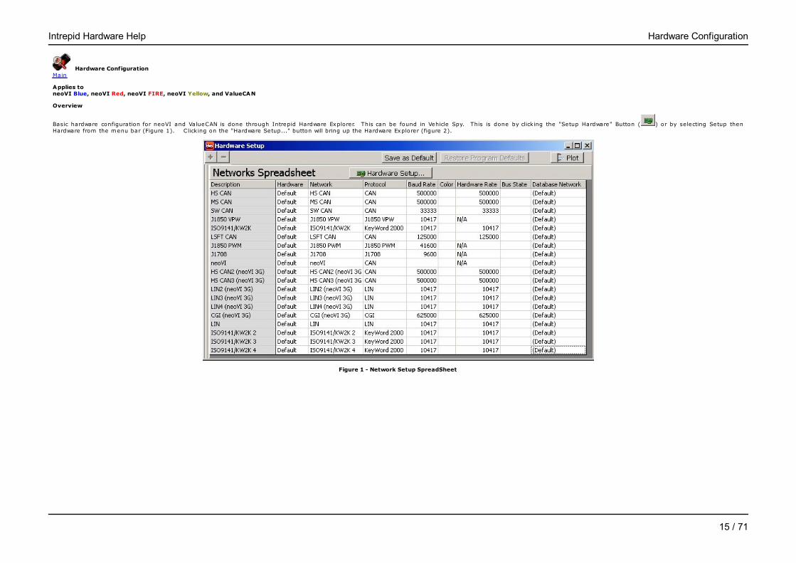
Basic hardware configuration for neoVI and ValueCAN is done through Intrepid Hardware Explorer. This can be found in Vehicle Spy. This is done by click ing the "Setup Hardware" Button ( ) or by selecting Setup thenHardware from the menu bar (Figure 1). Click ing on the "Hardware Setup..." button will bring up the Hardware Explorer (figure 2).
Figure 1 - Network Setup SpreadSheet
Intrepid Hardware Help Hardware Configuration
15 / 71

Figure 2 - neoVI Hardware Explorer
Connecting to a neoVI
You can select the device you want to connect to by selecting it in the list on the left (figure 2 : bubble 1). The "Connect" button (figure 2 : bubble 2) will connect to the hardware and read the settings currently stored in thedevice. The status window (figure 2 : bubble 2) notifies you if there are any issues talk ing to the hardware. The firmware versions are shown under Firmware (figure 2 : bubble 4). Device settings can be set to defaults byclick ing on the Load Defaults button (figure 2 : bubble 5) in the upper right.
neoVI Documentation - (C) Copyright 2000-2018 Intrepid Control Systems, Inc.
Last Update: Thursday, July 09, 2009
Intrepid Hardware Help Hardware Configuration
16 / 71
Firmware Maintenance - neoVIMain
Overview
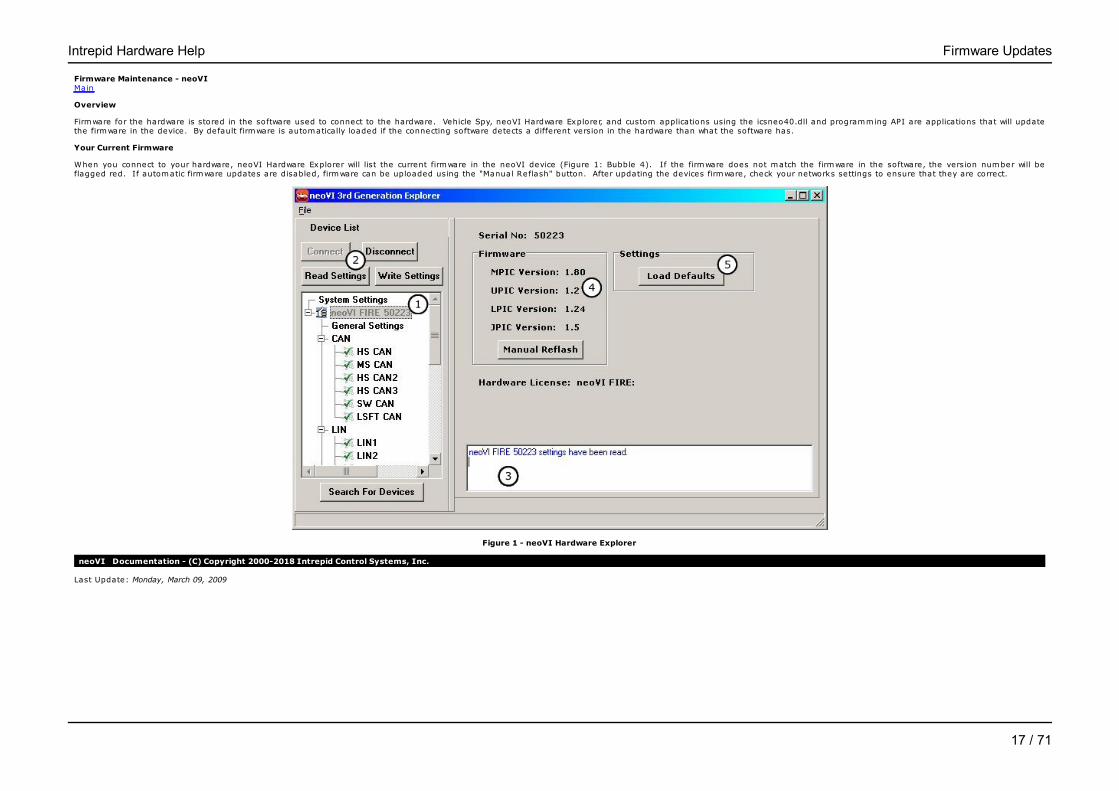
Firmware for the hardware is stored in the software used to connect to the hardware. Vehicle Spy, neoVI Hardware Explorer, and custom applications using the icsneo40.dll and programming API are applications that will updatethe firmware in the device. By default firmware is automatically loaded if the connecting software detects a different version in the hardware than what the software has.
Your Current Firmware
When you connect to your hardware, neoVI Hardware Explorer will list the current firmware in the neoVI device (Figure 1: Bubble 4). If the firmware does not match the firmware in the software, the version number will beflagged red. If automatic firmware updates are disabled, firmware can be uploaded using the "Manual Reflash" button. After updating the devices firmware, check your networks settings to ensure that they are correct.
Figure 1 - neoVI Hardware Explorer
neoVI Documentation - (C) Copyright 2000-2018 Intrepid Control Systems, Inc.
Last Update: Monday, March 09, 2009
Intrepid Hardware Help Firmware Updates
17 / 71
In-vehicle Networks - neoVIMain
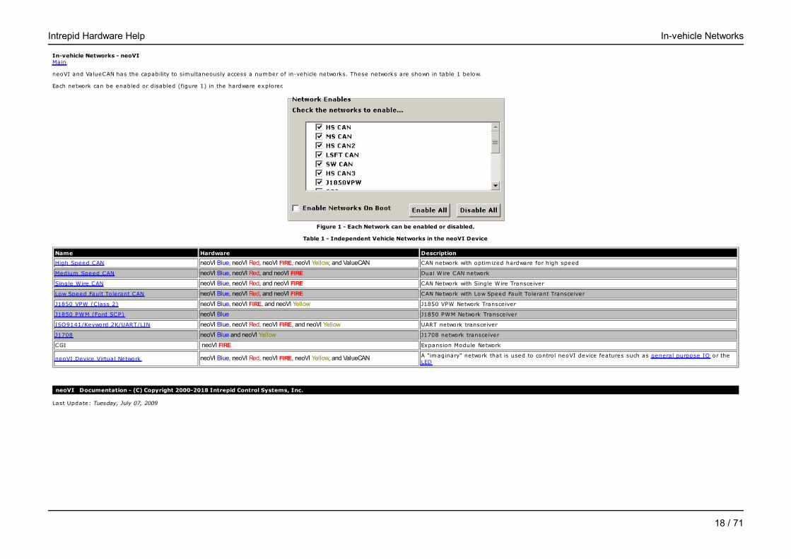
neoVI and ValueCAN has the capability to simultaneously access a number of in-vehicle networks. These networks are shown in table 1 below.
Each network can be enabled or disabled (figure 1) in the hardware explorer.
Figure 1 - Each Network can be enabled or disabled.
Table 1 - Independent Vehicle Networks in the neoVI Device
Name Hardware Description
High Speed CAN neoVI Blue, neoVI Red, neoVI FIRE, neoVI Yellow, and ValueCAN CAN network with optim ized hardware for high speed
Medium Speed CAN neoVI Blue, neoVI Red, and neoVI FIRE Dual Wire CAN network
Single Wire CAN neoVI Blue, neoVI Red, and neoVI FIRE CAN Network with Single Wire Transceiver
Low Speed Fault Tolerant CAN neoVI Blue, neoVI Red, and neoVI FIRE CAN Network with Low Speed Fault Tolerant Transceiver
J1850 VPW (Class 2) neoVI Blue, neoVI FIRE, and neoVI Yellow J1850 VPW Network Transceiver
J1850 PWM (Ford SCP) neoVI Blue J1850 PWM Network Transceiver
ISO9141/Keyword 2K/UART/LIN neoVI Blue, neoVI Red, neoVI FIRE, and neoVI Yellow UART network transceiver
J1708 neoVI Blue and neoVI Yellow J1708 network transceiver
CGI neoVI FIRE Expansion Module Network
neoVI Device Virtual Network neoVI Blue, neoVI Red, neoVI FIRE, neoVI Yellow, and ValueCAN A "imaginary" network that is used to control neoVI device features such as general purpose IO or theLED
neoVI Documentation - (C) Copyright 2000-2018 Intrepid Control Systems, Inc.
Last Update: Tuesday, July 07, 2009
Intrepid Hardware Help In-vehicle Networks
18 / 71
CAN Networks - neoVIMain
Applies to neoVI Blue, neoVI Red, neoVI FIRE, neoVI Yellow, and ValueCAN
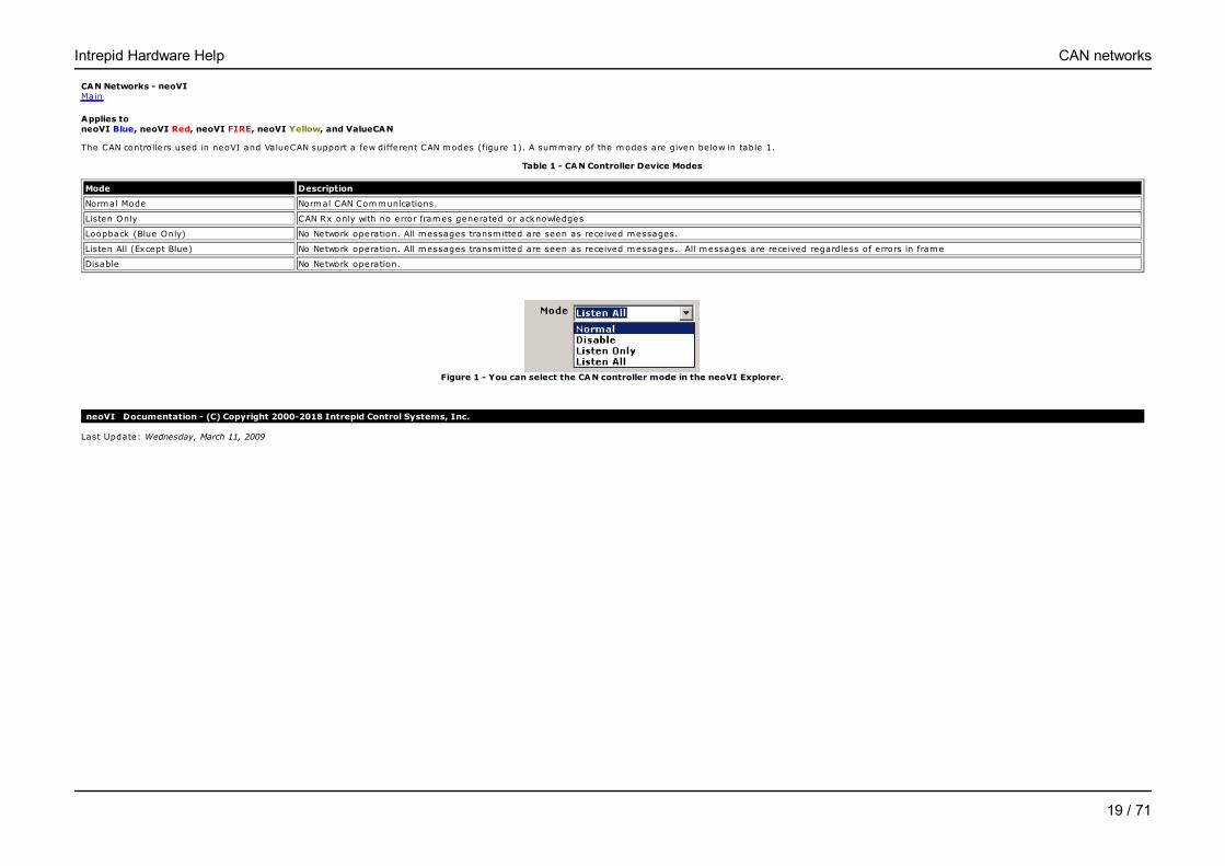
The CAN controllers used in neoVI and ValueCAN support a few different CAN modes (figure 1). A summary of the modes are given below in table 1.
Table 1 - CAN Controller Device Modes
Mode Description
Normal Mode Normal CAN Communications.
Listen Only CAN Rx only with no error frames generated or acknowledges
Loopback (Blue Only) No Network operation. All messages transmitted are seen as received messages.
Listen All (Except Blue) No Network operation. All messages transmitted are seen as received messages. All messages are received regardless of errors in frame
Disable No Network operation.
Figure 1 - You can select the CAN controller mode in the neoVI Explorer.
neoVI Documentation - (C) Copyright 2000-2018 Intrepid Control Systems, Inc.
Last Update: Wednesday, March 11, 2009
Intrepid Hardware Help CAN networks
19 / 71
High Speed CAN - neoVIMain
Applies to neoVI Blue, neoVI Red, neoVI FIRE, neoVI Yellow, and ValueCAN
The neoVI high speed CAN channel is an ISO11898 Dual Wire CAN Physical Layer (82C251) CAN channel. Like all CAN Channels, this channel has programmable baud rate/bit tim ing and CAN device mode. This channel isfunctionality equivalent to the medium speed channel except for that the neoVI circuits for high speed are optim ized.
According to the ISO11898 specification, the ends of the CAN network cabling should be term inated. This is described in a separate topic.
neoVI Documentation - (C) Copyright 2000-2018 Intrepid Control Systems, Inc.
Last Update: Wednesday, March 11, 2009
Intrepid Hardware Help High Speed CAN
20 / 71

Medium Speed CAN - neoVIMain
Applies to neoVI Blue, neoVI Red, and neoVI FIRE
The neoVI medium speed CAN channel is an ISO11898 Dual Wire CAN Physical Layer (82C251) CAN channel. Like all CAN Channels, this channel has programmable baud rate/bit tim ing and CAN device mode. This channel isfunctionality equivalent to the high speed channel except for that the neoVI circuits for the high speed channel are optim ized.
According to the ISO11898 specification, the ends of the CAN network cabling should be term inated. This is described in a separate topic.
neoVI Documentation - (C) Copyright 2000-2018 Intrepid Control Systems, Inc.
Last Update: Thursday, July 09, 2009
Intrepid Hardware Help Medium Speed CAN
21 / 71
Single Wire CAN - neoVIMain
Applies to neoVI Blue, neoVI Red, and neoVI FIRE
The neoVI single wire CAN channel is a GMW3089/ SAE J2411 (Silicon: TLE6255) CAN channel. Like all CAN Channels, this channel has programmable baud rate/bit tim ing and CAN device mode.
The single wire CAN physical layer contains three operational modes. They are the following 1) normal communication mode, 2) high-voltage wake up mode, and 3) high-speed mode. The default baud rate is used for normaland high-voltage modes. For the high-speed mode, you need to specify an additional baud rate (this is done on the High Speed Mode panel).
neoVI provides two modes for the high speed setting, one is used for monitoring high speed and the other is to operate as a test tool. GMW3089 requires a test tool to switch in a specified test tool resistor when transmitting inhigh speed mode.
neoVI Documentation - (C) Copyright 2000-2018 Intrepid Control Systems, Inc.
Last Update: Thursday, July 09, 2009
Intrepid Hardware Help Single Wire CAN
22 / 71

Low Speed Fault Tolerant CAN - neoVIMain
Applies to neoVI Blue, neoVI Red, and neoVI FIRE
The neoVI has an ISO11519 Low Speed Fault Tolerant CAN Physical Layer (TJA1054) CAN channel. Like all CAN Channels, this channel has programmable baud rate/bit tim ing and CAN device mode.
The Low Speed Fault Tolerant CAN network requires term ination with specific resistors. This is described in a separate topic.
neoVI Documentation - (C) Copyright 2000-2018 Intrepid Control Systems, Inc.
Last Update: Wednesday, March 11, 2009
Intrepid Hardware Help Low Speed Fault Tolerant CAN
23 / 71
CAN Bit Timing - neoVIMain
Applies to neoVI Blue, neoVI Red, neoVI FIRE, neoVI Yellow, and ValueCAN
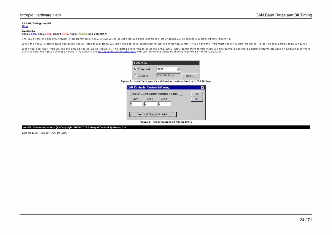
The Baud Rate of each CAN network is programmable. neoVI allows you to select a default baud rate from a list or allows you to specify a custom bit rate (figure 1).
While the neoVI explorer gives you default Baud Rates to pick from, you may need to have specific bit tim ing or another baud rate. If you have this, you must specify custom bit tim ing. To do this click edit as show in figure 1.
When you click "Edit", you will see the CAN Bit Tim ing Dialog (figure 2). This dialog allows you to enter the CNF1, CNF2, CNF3 parameters for the MCP2510 CAN controller. Intrepid Control Systems provides an additional softwareutility to help you figure out these values. This utility is the MCP2510 Bit tim ing calculator, you can launch this utility by click ing "Launch Bit Tim ing Calculator"
Figure 1 - neoVI lets specify a default or custom baud rate/bit timing.
Figure 2 - neoVI Custom Bit Timing Entry
neoVI Documentation - (C) Copyright 2000-2018 Intrepid Control Systems, Inc.
Last Update: Thursday, July 09, 2009
Intrepid Hardware Help CAN Baud Rates and Bit Timing
24 / 71
CAN Bit Timing Calculator - neoVIMain
Applies to neoVI Blue, neoVI Red, neoVI FIRE, neoVI Yellow, and ValueCAN
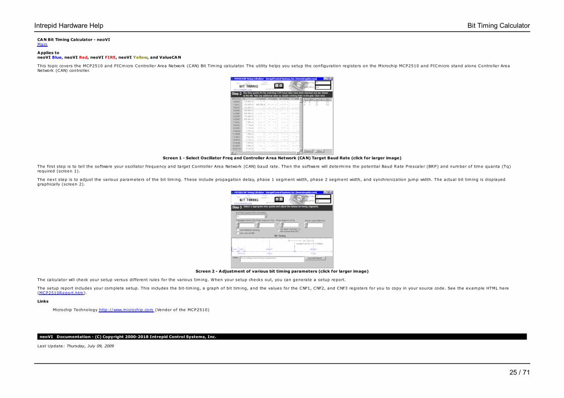
This topic covers the MCP2510 and PICmicro Controller Area Network (CAN) Bit Tim ing calculator. The utility helps you setup the configuration registers on the Microchip MCP2510 and PICmicro stand alone Controller AreaNetwork (CAN) controller.
Screen 1 - Select Oscillator Freq and Controller Area Network (CAN) Target Baud Rate (click for larger image)
The first step is to te ll the software your oscillator frequency and target Controller Area Network (CAN) baud rate. Then the software will determ ine the potential Baud Rate Prescaler (BRP) and number of time quanta (Tq)required (screen 1).
The next step is to adjust the various parameters of the bit tim ing. These include propagation delay, phase 1 segment width, phase 2 segment width, and synchronization jump width. The actual bit tim ing is displayedgraphically (screen 2).
Screen 2 - Adjustment of various bit timing parameters (click for larger image)
The calculator will check your setup versus different rules for the various tim ing. When your setup checks out, you can generate a setup report.
The setup report includes your complete setup. This includes the bit-tim ing, a graph of bit tim ing, and the values for the CNF1, CNF2, and CNF3 registers for you to copy in your source code. See the example HTML here(MCP2510Report.htm).
Links
Microchip Technology http://www.microchip.com (Vendor of the MCP2510)
neoVI Documentation - (C) Copyright 2000-2018 Intrepid Control Systems, Inc.
Last Update: Thursday, July 09, 2009
Intrepid Hardware Help Bit Timing Calculator
25 / 71

Terminating a Dual Wire CAN Network - neoVIMain
Applies to neoVI Blue, neoVI Red, neoVI FIRE, neoVI Yellow, and ValueCAN
Both the High Speed CAN and Medium Speed CAN channels require the ends of the CAN network to be term inated with a 120 ohm resistor.
Typically, if you are connecting to a existing CAN network these term ination resistors will be present. If you are building a test network you may have to install these resistors.
neoVI Documentation - (C) Copyright 2000-2018 Intrepid Control Systems, Inc.
Last Update: Thursday, July 09, 2009
Intrepid Hardware Help Terminating a Dual Wire CAN Network
26 / 71

Terminating a Low Speed Fault Tolerant CAN Network - neoVIMain
Applies to neoVI Blue, neoVI Red, and neoVI FIRE
The Low Speed Fault Tolerant CAN network requires each node to be term inated with two resistors. The size of the resistors are based on the overall number of nodes in the network.
Each nodes term ination resistors are in paralle l. The resulting resistance for all of the resistors should be between 100 and 500 ohms. neoVI ships with 510 ohm resistors installed.
The term ination resistors are installed in sockets on the neoVI printed circuit board. They can be replaced easily. Please see the hardware settings topic for information on how to change the term ination resistors.
Please see the TJA1054 data sheet and related application notes for further information on Low Speed Fault Tolerant CAN network term ination and network design.
neoVI Documentation - (C) Copyright 2000-2018 Intrepid Control Systems, Inc.
Last Update: Thursday, July 09, 2009
Intrepid Hardware Help Terminating a Low Speed Fault Tolerant CAN Network
27 / 71

J1850 VPW (Class 2) - neoVIMain
Applies to neoVI Blue, neoVI FIRE, and neoVI Yellow
The network protocol does not use a specific J1850 protocol chip, it generates the VPW symbols with a software peripheral. There are no settings for this network.
neoVI Documentation - (C) Copyright 2000-2018 Intrepid Control Systems, Inc.
Last Update: Wednesday, March 11, 2009
Intrepid Hardware Help J1850 VPW (Class 2)
28 / 71

J1850 PWM (Ford SCP) - neoVIMain
Applies to neoVI Blue
To implement J1850 PWM communications neoVI uses the Ford SCP LBCC communications IC with the Ford specified physical layer. It optionally lets you monitor the entire network using special monitor mode firmware. TheLBCC IC allows you to setup a number of parameters that control its operation. When enabled, the neoVI Firmware supplies monitor mode and the LBCC provides transmit operations.
First, you can set the bit rate of the SCP network (figure 1 : bubble 1). The standard network bit rate is 41.6 kbps. The higher speed 83.3 kbps is sometimes used on the network for special network operations. Special Monitor mode only supports the 41.6 kbps rate.
The OBD connector used in neoVI connects the J1850 VPW network to the J1850 + line. neoVI contains a relay the can switch the JPWM + signal on to that line instead of JVPW. This allows you to use one connector with both protocols. You can have neoVI default toeither connecting VPW (default) or PWM (Figure 1: bubble 2). You can control the relay at run time using a neoVI virtual network can message.
You can set the Node Address of the Ford SCP node. This is shown in the figure 1: bubble 3. This is used for setting the source id and is used when the LBCC generates In frame responses (IFRs). This address must be unique for each node on the SCP network.
Next, you can set the Network Driver and Receive Control Register (NDRC) of the LBCC. This is shown in figure 1 bubble 4. The NDRC is a register in the LBCC which allows you to transmit or receive on portions of the dual wire network. Normally, theseshould all be checked.
The LBCC allows you to optionally handle two function read data message parameters. These are setup in figure 1 : bubble 5. If you want to handle a function read data message, check the number 1 or 2 and enter thefunction code. These settings are entered in Lookup Table 2 of the LBCC device. You can set the actual data for the function code with the "LBCC Set FRead data" neoVI virtual network command.
You can setup the LBCC look up table 1 (figure 2). Lookup table 1 controls what functional messages the LBCC should receive. You can have up to 31 entries in this table. In figure 2, we setup the LBCC to receive threefunctional messages including 0x1E, 0xF1, and 0x22. Blank spaces in the table are ignored.
Special Monitor mode allows you to monitor all traffic on the SCP network. To enable this node click the check box in figure 1 bubble 6. This enables special firmware in neoVI that monitors and decodes the raw SCP waveform. When this is done, both J1850 VPW andISO/KW2k protocols are disabled. You can still use the Ford LBCC channel. All monitor mode messages come across on the J1850VPW network.
Node Address - The SCP Node address is used for three purposes. First, the node address is the third byte of every transmitted message (the source address). Next, the address is used for node address acknowledgement.Finally, it is used to determ ine which physically addressed SCP messages should be received.
Tx Driver Enable -These two bits enable network drivers A (bus -) and b (bus +). When set, each bit will enable the corresponding output pin driver. When the bit is clear the pin is tristated.
Rx Enable Bits - These three bits control the inputs into the LBCC bit decoder. The receivers are enabled when the bits are a "1". Disabled receivers force a "stuck active" condition to the bit decoders.
Figure 1 - The LBCC Node Address, NDRC, and Function Read Data Codes Setup
Intrepid Hardware Help J1850 PWM (Ford PWM)
29 / 71
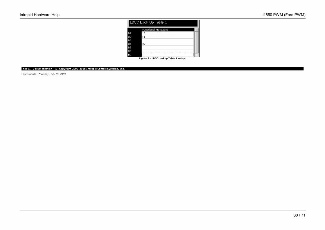
Figure 2 - LBCC Lookup Table 1 setup.
neoVI Documentation - (C) Copyright 2000-2018 Intrepid Control Systems, Inc.
Last Update: Thursday, July 09, 2009
Intrepid Hardware Help J1850 PWM (Ford PWM)
30 / 71

J1708 - neoVIMain
Applies to neoVI Blue, and neoVI Yellow
There are no settings for this network.
neoVI Documentation - (C) Copyright 2000-2018 Intrepid Control Systems, Inc.
Last Update: Wednesday, March 11, 2009
Intrepid Hardware Help J1708
31 / 71
UART/ISO9141/KW2K/LIN - neoVIMain
Applies to neoVI Blue, neoVI Red, neoVI FIRE, and neoVI Yellow
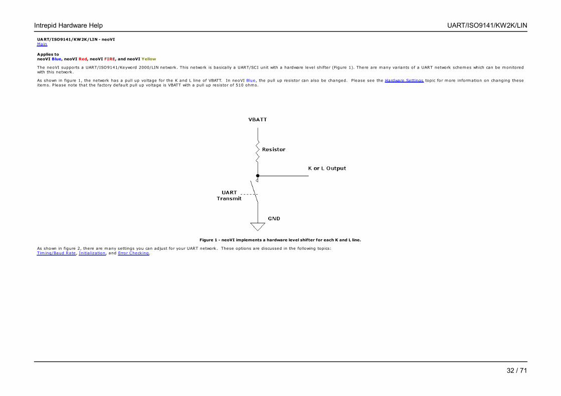
The neoVI supports a UART/ISO9141/Keyword 2000/LIN network. This network is basically a UART/SCI unit with a hardware level shifter (Figure 1). There are many variants of a UART network schemes which can be monitoredwith this network.
As shown in figure 1, the network has a pull up voltage for the K and L line of VBATT. In neoVI Blue, the pull up resistor can also be changed. Please see the Hardware Settings topic for more information on changing theseitems. Please note that the factory default pull up voltage is VBATT with a pull up resistor of 510 ohms.
Figure 1 - neoVI implements a hardware level shifter for each K and L line.
As shown in figure 2, there are many settings you can adjust for your UART network. These options are discussed in the following topics: Tim ing/Baud Rate, Initia lization, and Error Checking.
Intrepid Hardware Help UART/ISO9141/KW2K/LIN
32 / 71
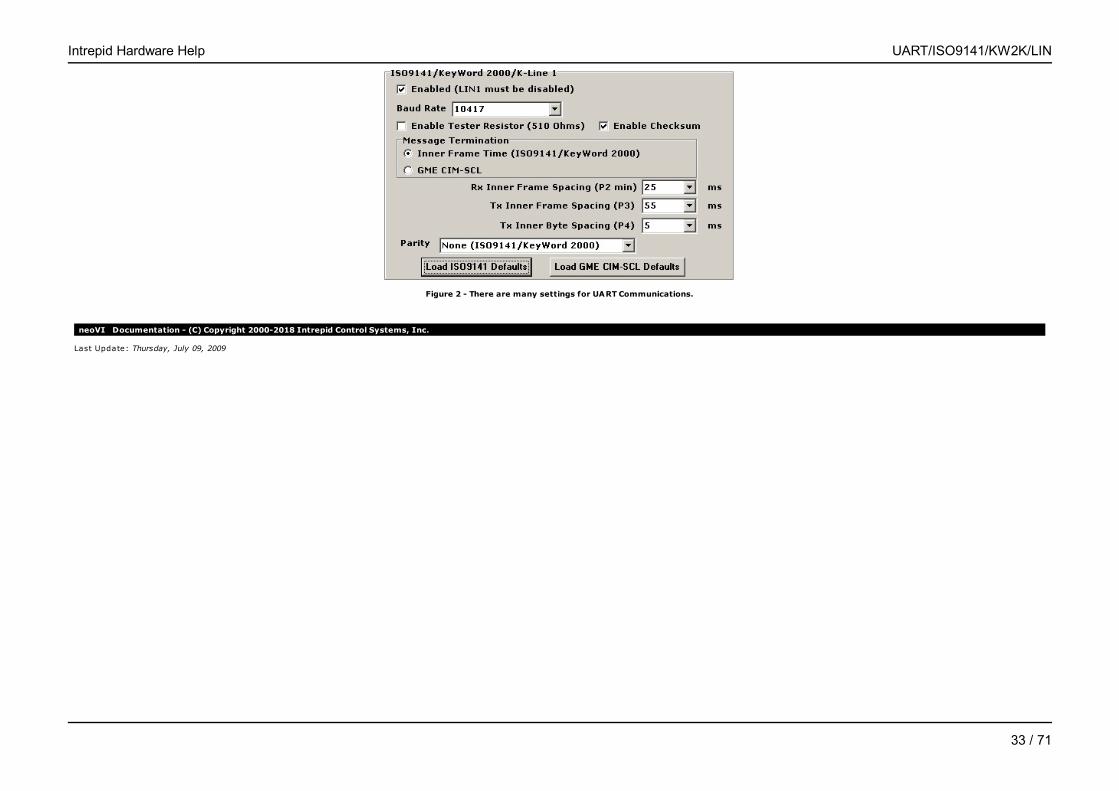
Figure 2 - There are many settings for UART Communications.
neoVI Documentation - (C) Copyright 2000-2018 Intrepid Control Systems, Inc.
Last Update: Thursday, July 09, 2009
Intrepid Hardware Help UART/ISO9141/KW2K/LIN
33 / 71
UART Timing - neoVIMain
Applies to neoVI Blue, neoVI Red, neoVI FIRE, and neoVI Yellow
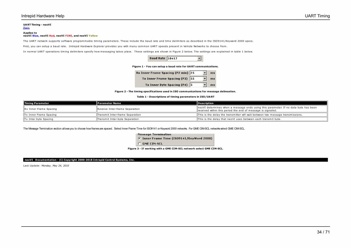
The UART network supports software programmable tim ing parameters. These include the baud rate and time delim iters as described in the ISO9141/Keyword 2000 specs.
First, you can setup a baud rate. Intrepid Hardware Explorer provides you with many common UART speeds present in Vehicle Networks to choose from.
In normal UART operations tim ing delim iters specify how messaging takes place. These settings are shown in Figure 2 below. The settings are explained in table 1 below.
Figure 1 - You can setup a baud rate for UART communications.
Figure 2 - The timing specifications used in ISO communications for message delineation.
Table 1 - Descriptions of timing parameters in ISO/UART
Timing Parameter Parameter Name Description
Rx Inner Frame Spacing Receive Inter-frame SeparationneoVI determ ines when a message ends using this parameter. If no data byte has beenreceived within this period the end of message is signaled.
Tx Inner Frame Spacing Transmit Inter-frame Separation This is the delay the transmitter will wait between two message transmissions.
Tx Inter byte Spacing Transmit Inter-byte Separation This is the delay that neoVI uses between each transmit byte.
The Message Termination section allows you to choose how frames are spaced. Select Inner Frame Time for ISO9141 or Keyword 2000 networks. For GME CIM-SCL networks select GME CIM-SCL.
Figure 3 - If working with a GME CIM-SCL network select GME CIM-SCL.
neoVI Documentation - (C) Copyright 2000-2018 Intrepid Control Systems, Inc.
Last Update: Monday, May 24, 2010
Intrepid Hardware Help UART Timing
34 / 71
UART Initialization Waveforms - neoVIMain
Applies to neoVI Blue, neoVI Red, neoVI FIRE, and neoVI Yellow
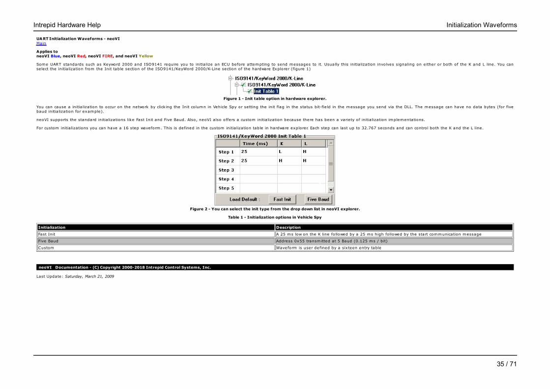
Some UART standards such as Keyword 2000 and ISO9141 require you to initia lize an ECU before attempting to send messages to it. Usually this initia lization involves signaling on either or both of the K and L line. You canselect the initia lization from the Init table section of the ISO9141/KeyWord 2000/K-Line section of the hardware Explorer (figure 1)
Figure 1 - Init table option in hardware explorer.
You can cause a initia lization to occur on the network by click ing the Init column in Vehicle Spy or setting the init flag in the status bit-fie ld in the message you send via the DLL. The message can have no data bytes (for fivebaud initia lization for example).
neoVI supports the standard initia lizations like Fast Init and Five Baud. Also, neoVI also offers a custom initia lization because there has been a variety of initia lization implementations.
For custom initia lizations you can have a 16 step waveform. This is defined in the custom initia lization table in hardware explorer. Each step can last up to 32.767 seconds and can control both the K and the L line.
Figure 2 - You can select the init type from the drop down list in neoVI explorer.
Table 1 - Initialization options in Vehicle Spy
Initialization Description
Fast Init A 25 ms low on the K line followed by a 25 ms high followed by the start communication message
Five Baud Address 0x55 transmitted at 5 Baud (0.125 ms / bit)
Custom Waveform is user defined by a sixteen entry table
neoVI Documentation - (C) Copyright 2000-2018 Intrepid Control Systems, Inc.
Last Update: Saturday, March 21, 2009
Intrepid Hardware Help Initialization Waveforms
35 / 71
UART Error Checking - neoVIMain
Applies to neoVI Blue, neoVI Red, neoVI FIRE, and neoVI Yellow
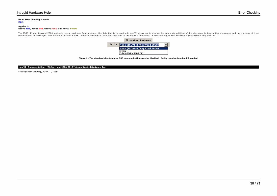
The ISO9141 and Keyword 2000 protocols use a checksum fie ld to protect the data that is transmitted. neoVI allows you to disable the automatic addition of this checksum to transmitted messages and the checking of it onthe reception of messages. This maybe useful for a UART protocol that doesn't use the checksum or calculates it differently. A parity setting is also available if your network requires this.
Figure 1 - The standard checksum for ISO communications can be disabled. Parity can also be added if needed.
neoVI Documentation - (C) Copyright 2000-2018 Intrepid Control Systems, Inc.
Last Update: Saturday, March 21, 2009
Intrepid Hardware Help Error Checking
36 / 71

LIN : Local Interconnect Network - neoVIMain
Applies to neoVI Blue, neoVI Red, neoVI FIRE, and neoVI Yellow
neoVI supports communication on LIN (Local Interconnect Network).
Once detecting a proper Sync Break and Sync fie ld, the neoVI will wait for the Msg Identifier fie ld. The message reception will begin with the Msg ID fie ld. The neoVI will receive the entire message according to the LIN spec. After receiving the message error free, the neoVI will send the received message to the host starting with the Msg ID fie ld.
If there are any errors neoVI will report the errors back to the host. Table 1 below lists the errors checked for by the neoVI device.
neoVI supports acting as a monitor, master, and slave.
Enabling LIN is done in the Hardware Explorer. For neoVI Blue LIN is enabled under the ISO9141/KWord 2K/UART/LIN options. Set the Mode to "LIN Mode" and the "Rx Transceiver" to LIN. Also make sure the baud rate iscorrect for your network (Figure 1).
Figure 1 -LIN mode is entered via the neoVI Explorer.
To Enable LIN on a neoVI FIRE, neoVI Red, and neoVI Yellow is done in Hardware Explorer by Selecting the channel under network Enables and then setting the proper baud rate for that LIN channel (Figure 2)
Figure 2 -LIN mode is enabled via the neoVI 3G Explorer.
Figure 3 - A LIN Message
Table 1 - Errors detected in LIN mode.
Error Description
ISO_LIN_SYNC_BRK_ERR The Sync Break did not have all zero's
ISO_LIN_SYNC_LEN_ERR The Sync Break did not have at least 9 zero's
ISO_LIN_SYNC_WAV_ERR The Sync Waveform received after a valid Sync Break was not 0x55
ISO_LIN_MSG_ID_PRTY The MSG ID fie ld was not valid based on the MSG ID parity bits
neoVI Documentation - (C) Copyright 2000-2018 Intrepid Control Systems, Inc.
Last Update: Monday, June 01, 2009
Intrepid Hardware Help Local Interconnect Network (LIN)
37 / 71
LIN Slave Table - neoVIMain
Applies to neoVI Blue, neoVI Red, neoVI FIRE, and neoVI Yellow
LIN Slave messages sent to the hardware are stored in the hardware's internal slave table until it is requested by a master message request. Data in the internal Slave Table can updated by resending the slave message inyour software application. When a master request is received by the hardware, the latest data for that ID in the LIN Slave table will be sent.
neoVI Documentation - (C) Copyright 2000-2018 Intrepid Control Systems, Inc.
Last Update: Monday, June 01, 2009
Intrepid Hardware Help LIN Slave Table
38 / 71

Hardware Features - neoVIMain
Applies to neoVI Blue, neoVI Red, neoVI FIRE, neoVI Yellow, and ValueCAN
Because of the differences in hardware, these sections are split up between the different hardware types.
- neoVI Blue
- neoVI RED \ neoVI FIRE
- neoVI Yellow
- ValueCAN3
neoVI Documentation - (C) Copyright 2000-2018 Intrepid Control Systems, Inc.
Last Update: Thursday, July 09, 2009
Intrepid Hardware Help Hardware Features
39 / 71
Hardware Features Main
Applies to neoVI Blue
The neoVI device has many configurable features which are not in-vehicle networks. This section details them. This section also contains the neoVI theory of operation. The hardware features discussed in this section includethe following:
1) neoVI LED2) General Purpose IO3) DAQ Pacer Clock4) Specifications5) Hardware Settings
neoVI Documentation - (C) Copyright 2000-2018 Intrepid Control Systems, Inc.
Last Update: Thursday, July 09, 2009
Intrepid Hardware Help neoVI Blue
40 / 71

Theory of Operation - neoVIMain
Applies to neoVI Blue
This section details the theory-of-operation of the neoVI device. A block diagram of the device is shown in figure 1 below.
The neoVI device consists of three independent µControllers which have a total of 20 MIPS (m illions of instructions per second) of processing power. This processing power can read messages from 9 independent networks. Afterreading the messages the neoVI can do one or all of the following things: 1) send them to the PC via RS232 or USB, 2) process the message, or 3) store the message in onboard storage.
The functionality of the neoVI is based on its firmware. All three of the µControllers in the neoVI device have fie ld upgradeable firmware. This means the neoVI device can be updated with new functionality at anytime in thefuture.
The following topics explain the diagram further: 1) Main 51 µController, 2) Main PIC µController, 3) CAN Networks, 4) LBCC Protocol IC, and 5) ISO/J PIC µController section.
Figure 1 - the neoVI block diagram (click for larger image)
Main 51 µController
The Main 51 µController (figure 2) is responsible for collecting messages from the Main PIC µController and processing them. Normally, when neoVI is used as a PC interface this means sending them to the PC via USB orRS232. It also could store the messages on it's MMC (multimedia card storage device). It could also process the messages and do something such as transmit a response or change a general purpose IO bit.
The RS232 port is capable of 115.2 kb, 57.6 kb, 38.4 kb, 28.8 kb, 19.2 kb, 9600 bps, and 4800 bps baud rates. It includes RS232 control lines for hardware handshaking (RTS/CTS) and DTR acting as a DCE (DataCommunication Equipment) device.
The USB port supports USB 1.1 full speed 12 Mega-Bits per second. The device is software programmable to use either Bulk only or Isochronous in/bulk out transfers.
The neoVI device defaults to 56k Baud RS232 communication on power up. The communication can then be changed by the host software by sending commands on USB or RS232.
Figure 2 - The Main 51 µController
Main PIC µController
Intrepid Hardware Help Theory of Operation
41 / 71
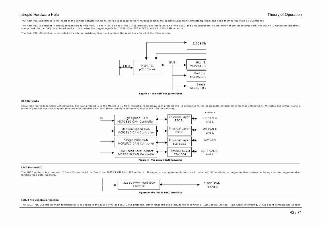
The Main PIC µController is the heart of the Vehicle network functions. Its job is to read network messages from the specific subsections, timestamp them and send them to the Main 51 µController.
The Main PIC µController is directly responsible for the MISC 1 and MISC 2 signals, the J1708 protocol, and configuration of the LBCC and CAN controllers. As the owner of the timestamp clock, the Main PIC generates the time-stamp clock for the DAQ pacer functionality. It a lso owns the trigger signals for J1708, Ford SCP (LBCC), and all of the CAN networks.
The Main PIC µController is protected by a internal watchdog timer and controls the reset lines for all of the other circuits.
Figure 3 - The Main PIC µController
CAN Networks
neoVI has four independent CAN networks. The CAN protocol IC is the MCP2510 IC from Microchip Technology. Each protocol chip, is connected to the appropriate physical layer for that CAN network. All status and control signalsfor each physical layer are mapped to internal µController pins. This allows complete software control of the CAN functionality.
Figure 4 - The neoVI CAN Networks
LBCC Protocol IC
The LBCC protocol is a protocol IC from Visteon which performs the J1850 PWM Ford SCP protocol. It supports a programmable function id table with 31 locations, a programmable network address, and two programmablefunction read data registers.
Figure 5- The neoVI LBCC interface
ISO/J PIC µController Section
The ISO/J PIC µController main functionality is to generate the J1850 VPW and ISO/UART protocols. Other responsibilities include the following: 1) LED Control, 2) Real-Time Clock Interfacing, 3) On-board Temperature Sensor
Intrepid Hardware Help Theory of Operation
42 / 71
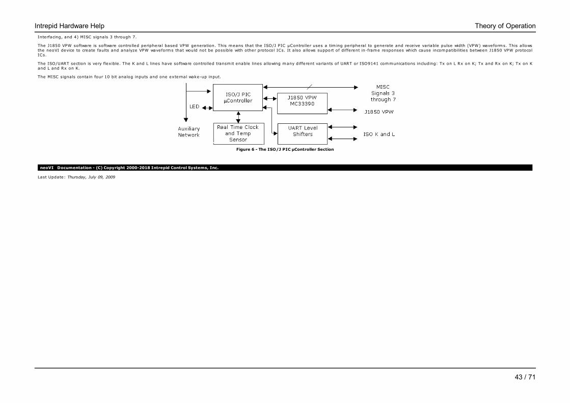
Interfacing, and 4) MISC signals 3 through 7.
The J1850 VPW software is software controlled peripheral based VPW generation. This means that the ISO/J PIC µController uses a tim ing peripheral to generate and receive variable pulse width (VPW) waveforms. This allowsthe neoVI device to create faults and analyze VPW waveforms that would not be possible with other protocol ICs. It also allows support of different in-frame responses which cause incompatibilities between J1850 VPW protocolICs.
The ISO/UART section is very flex ible. The K and L lines have software controlled transmit enable lines allowing many different variants of UART or ISO9141 communications including: Tx on L Rx on K; Tx and Rx on K; Tx on Kand L and Rx on K.
The MISC signals contain four 10 bit analog inputs and one external wake-up input.
Figure 6 - The ISO/J PIC µController Section
neoVI Documentation - (C) Copyright 2000-2018 Intrepid Control Systems, Inc.
Last Update: Thursday, July 09, 2009
Intrepid Hardware Help Theory of Operation
43 / 71

LED - neoVIMain
Applies to neoVI Blue
The behavior of the neoVI LED is programmable. The LED can be setup to activate on network activity, display the state of a MISC pin, or change state according to a script. You can setup this behavior in the neoVI Explorer.
The LED Operating Mode selection (figure 1 : bubble 1) sets the behavior. The LED settings are listed in Table 1 below.
For settings that cause the LED to flash the neoVI provides two additional settings. The first setting is the flash type. You can either have the LED turn green and then turn off or flash green and resume red flashing. The secondsetting is the flash duration. This is the time the green element is active for each flash.
The LED can also be controlled through the neoVI Device virtual network.
Figure 1 - How the neoVI LED works can be set in neoVI explorer.
Table 1 - The LED Operating Modes
LED Operating Mode Description
Standard ModeThe standard LED setting. This setting will cause the LED to toggle between Red and off every 104 ms. You canalso control the LED with scripts using this setting.
Display MISC3 Displays the state of the MISC3 pin. It will display green if the pin is on otherwise it will be off.
Display MISC4 Displays the state of the MISC4 pin. It will display green if the pin is on otherwise it will be off.
Display MISC5 Displays the state of the MISC5 pin. It will display green if the pin is on otherwise it will be off.
Display MISC6 Displays the state of the MISC6 pin. It will display green if the pin is on otherwise it will be off.
Display MISC7 Displays the state of the MISC7 pin. It will display green if the pin is on otherwise it will be off.
neoVI Documentation - (C) Copyright 2000-2018 Intrepid Control Systems, Inc.
Last Update: Wednesday, July 15, 2009
Intrepid Hardware Help LED
44 / 71

General Purpose IO Main
Applies to neoVI Blue
Overview
neoVI has six general purpose 5 VDC IO pins. These are labeled as MISC signals on the neoVI connector. These pins can be used for controlling or monitoring external devices.
Basic Setup
The general purpose IO are setup in the neoVI explorer. The general IO tree node is shown in figure 1. On the panel you can setup the direction, type, and initia l state of each IO pin.
Each MISC signal has a drop down box (figure 1 : bubble 1). In this drop down box you can set if the MISC pin is an input, output initia lly off, or an output initia lly on.
The outputs are capable of LED drive through a current lim iting resistor. The maximum current of all outputs should not exceed 50 mA. For protection, each IO pin has a series 100 ohm resistor and a transient protectiondevice.
Analog Inputs
If setup as input, MISC pins 3 through 6 can be setup as analog inputs. You can setup analog inputs via the "Analog Setting" drop down (figure 1 : bubble 2). The settings are : 1) no analog inputs, 2) analog input on MISC 3,and 3) analog inputs on MISC 3-6.
When setting up MISC3 only, the sampling rate will be once per m illisecond. If the setting is for MISC3-6, the sample rate will be every four m illiseconds.
General IO Reporting
You can setup the general IO to be automatically reported to the host in neoVI explorer (figure 2). You can setup the general IO to be reported at an interval or based on digital inputs changing (figure 2 : bubble 1). Thereport will be sent to the host as a neoVI Device Virtual Network message.
When reporting based on interval is selected you can select the interval from the drop down box shown in bubble 2 in figure 2. You can select an interval from 1 to 125 ms.
If you selected a report based on digital change, you can select both an interval the inputs are tested (figure 2 : bubble 2) and which digital inputs to test (figure 2 : bubble 3). You can select as many as are listed.
The report based on digital change will "de-bounce" the reading by testing the inputs twice. Each test will occur at one-half the time interval.
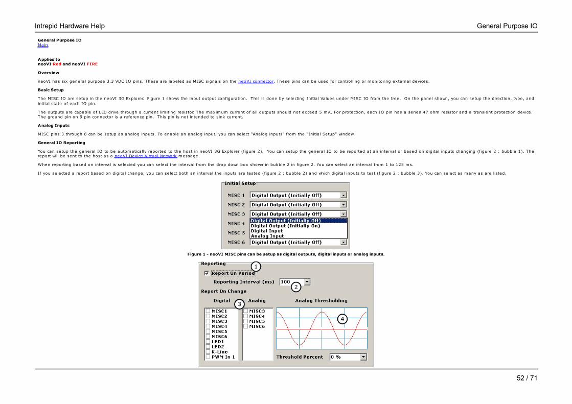
Figure 1 - neoVI MISC pins can be setup as digital outputs, digital inputs or analog inputs.
Intrepid Hardware Help General Purpose IO
45 / 71
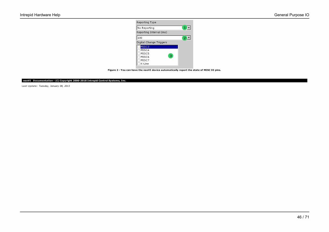
Figure 2 - You can have the neoVI device automatically report the state of MISC IO pins.
neoVI Documentation - (C) Copyright 2000-2018 Intrepid Control Systems, Inc.
Last Update: Tuesday, January 08, 2013
Intrepid Hardware Help General Purpose IO
46 / 71
DAQ Pacer Clock - neoVIMain
Applies to neoVI Blue
Overview
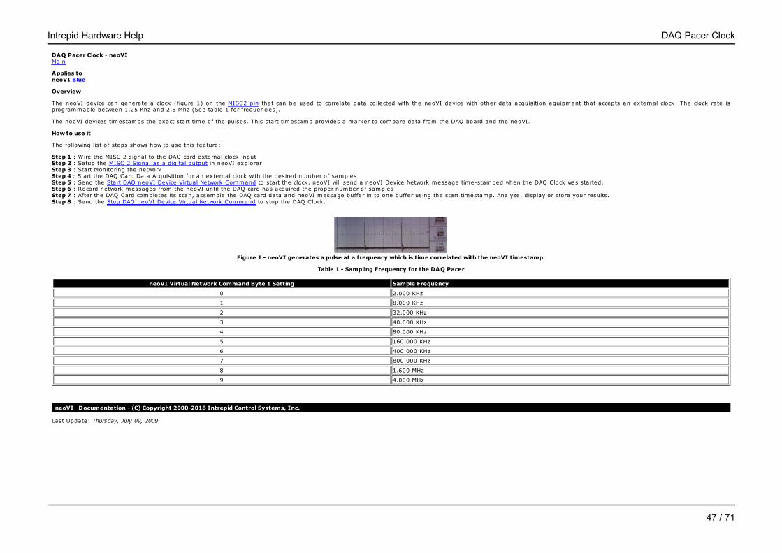
The neoVI device can generate a clock (figure 1) on the MISC2 pin that can be used to correlate data collected with the neoVI device with other data acquisition equipment that accepts an external clock. The clock rate isprogrammable between 1.25 Khz and 2.5 Mhz (See table 1 for frequencies).
The neoVI devices timestamps the exact start time of the pulses. This start timestamp provides a marker to compare data from the DAQ board and the neoVI.
How to use it
The following list of steps shows how to use this feature:
Step 1 : Wire the MISC 2 signal to the DAQ card external clock inputStep 2 : Setup the MISC 2 Signal as a digital output in neoVI explorerStep 3 : Start Monitoring the networkStep 4 : Start the DAQ Card Data Acquisition for an external clock with the desired number of samplesStep 5 : Send the Start DAQ neoVI Device Virtual Network Command to start the clock. neoVI will send a neoVI Device Network message time-stamped when the DAQ Clock was started.Step 6 : Record network messages from the neoVI until the DAQ card has acquired the proper number of samplesStep 7 : After the DAQ Card completes its scan, assemble the DAQ card data and neoVI message buffer in to one buffer using the start timestamp. Analyze, display or store your results.Step 8 : Send the Stop DAQ neoVI Device Virtual Network Command to stop the DAQ Clock.
Figure 1 - neoVI generates a pulse at a frequency which is time correlated with the neoVI timestamp.
Table 1 - Sampling Frequency for the DAQ Pacer
neoVI Virtual Network Command Byte 1 Setting Sample Frequency
0 2.000 KHz
1 8.000 KHz
2 32.000 KHz
3 40.000 KHz
4 80.000 KHz
5 160.000 KHz
6 400.000 KHz
7 800.000 KHz
8 1.600 MHz
9 4.000 MHz
neoVI Documentation - (C) Copyright 2000-2018 Intrepid Control Systems, Inc.
Last Update: Thursday, July 09, 2009
Intrepid Hardware Help DAQ Pacer Clock
47 / 71
Specifications Main
Applies to neoVI Blue
Device
* Power Consumption (typical) : 150mA @ 14.4 VDC* Sleep Mode Power Consumption (typical) : 3mA @ 14.4 VDC * Power Supply: vehicle compatible 5.5-20.0 VDC* Physical Dimensions : 120 x 70 x 25 mm ( 4.8 " x 2.8 " x 1.0" )* Weight: 113 g ( 4 oz )* Non USB Temperature Range: -40 to 85 C* USB Temperature Range: 0 to 70 C * Vehicle Connector : 25 Pin male D-SUB* Standard PC/Host Connectors: USB downstream, RS232 9PIN D-SUB Female* RS232 port capable of 115.2 kb, 57.6 kb, 38.4 kb, 28.8 kb, 19.2 kb, 9600 bps, and 4800 bps baud rates. Control lines include hardware handshaking (RTS/CTS) and DTR acting as a DCE (Data Communication Equipment)device.* Warranty: One year lim ited warranty* Firmware: Fie ld upgradeable design (flash EEPROM)* On board Processing: 20 MIPS RISC based multi-controller design* Expansion: Internal 5Mhz SPI interface and External Device Timestamp Synchronization* Bicolor user notification LED (red-green) is user configurable or can change on network activity, trigger or IO pin.* General Purpose IO: Seven IO configurable as input or output. Four configurable as 10 bit analog inputs. One configurable for external wakeup. ISO K and L Lines available as general purpose outputs. K Line available isgeneral purpose input.* General Purpose IO rate report interval 1-100 ms or based on digital change. Analog input sampling rate is 1 ms per channel.* On board 9-bit IC temperature sensor with a range of -55 to 125 C (-67 to 257 F) .* On board non-volatile storage: 32KByte EEPROM and MMC (Multimedia Card Card) slot for up to 64Mbytes of on board storage.* EMI Shie lded Enclosure* Emulation of General Motors VSI Interface via RS232
Networks - General
* Time stamping to accuracy of 100uS on CAN networks, J1708 network, and Ford SCP network. 250 µs on Class 2 / J1850 VPW and ISO/KW2K. Timestamp rollover is greater than 1 year.* Simultaneous operations on all networks with aggregate bandwidth performance of 2 mega baud over USB.* Transmit message double-buffering on all networks allows back to back message transmission.* Multiple hardware triggers allow bit-wise filter specifications on entire message (first 12 bytes for block type messages)* Generation of scan clock with correlated start message timestamp for synchronization of external data acquisition equipment* Device wake up on network activity on any network.
High Speed CAN
* ISO11898 Dual Wire CAN Physical Layer (82C251)* CAN 2.0B active* MCP2510 CAN controller with support for loop-back and listen-only operation.* Optim ized Rx and Tx circuitry* Up to 1 M-Bit software selectable baud rate* Graphical Bit Time/Baud Rate Calculator
Medium Speed CAN
* ISO11898 Dual Wire CAN Physical Layer (82C251)* CAN 2.0B active* MCP2510 CAN controller with support for loop-back and listen-only operation.* Up to 1 M-Bit software selectable baud rate* Graphical Bit Time/Baud Rate Calculator
Low Speed Fault Tolerant CAN
* ISO11519 Low Speed Fault Tolerant CAN Physical Layer (TJA1054)* CAN 2.0B active* MCP2510 CAN controller with support for loop-back and listen-only operation.* Software selectable baud rate/bit tim ing up to lim itations of physical layer.* Graphical Bit Time/Baud Rate Calculator
Single Wire CAN
* Single Wire CAN physical layer GMW3089/ SAE J2411 (TLE6255)* CAN 2.0B active* MCP2510 CAN controller with support for loop-back and listen-only operation.* High Speed Mode, High Speed Test Tool Mode, and High Voltage Wakeup support
Intrepid Hardware Help Specifications
48 / 71
* Software selectable baud rate/bit tim ing up to lim itations of physical layer.* Graphical Bit Time/Baud Rate Calculator
GM Class 2/ SAE J1850 VPW
* VPW Physical Layer capable of Tx and Rx operations in high speed modes (MC33390)* Software controlled peripheral based VPW generation* Software modifiable bit tim ing acceptance parameters* Software modifiable bit tim ing generation parameters* Trigger generation based on network error or lost arbitration event* Bad CRC generation* 4x high speed mode (lim ited simultaneous operations at 41.6 k-bits)* Block transfer mode* Break generation* Bad Message generation capable
UART/ISO9141/Keyword 2000 (ISO14230)
* K and L lines implemented* UART Based state machine* Initia lization waveforms including Fast Init, Five Baud, CARB and Custom* Programmable tim ing parameters including inter-byte, TX inter-frame, RX inter-frame and initia lization waveforms (0.5 ms resolution)* Software selectable baud rate* Socket selectable pull up resistor on both K and L lines* Jumper selectable pull up voltage either 5V or Battery* K and L have software controlled transmit enable lines allowing many different variants of UART or ISO9141 communications including: Tx on L Rx on K; Tx and Rx on K; Tx on K and L and Rx on K
Ford SCP/ SAE J1850 PWM
* Dual BCC Design : LBCC Communications Protocol IC Tx/Rx with optional "Monitor Mode" performed by a additional processor * Software setup of LBCC including the Node Address, Lookup Table 1 and 2, and the Network Driver and Receive Control Register* Software selectable SCP bit rate of 41.6 kbps or 83.3 kbps* Dynamic Node Address mode: LBCC is reconfigured when a message to be transmitted has a different node address then previously configured
SAE J1708
* SAE J1708 Physical Layer* Software setup of SAE J1708 parameters
neoVI Documentation - (C) Copyright 2000-2018 Intrepid Control Systems, Inc.
Last Update: Wednesday, June 04, 2014
Intrepid Hardware Help Specifications
49 / 71

Hardware Settings - neoVIMain
Applies to neoVI Blue
While most neoVI settings are software programmable a few are set with hardware. The following items are set in hardware: 1) the term ination resistors for low speed fault tolerant CAN, 2) the pull up resistors for theUART/ISO/Keyword 2k network, 3) the J1850 PWM LBCC network, and 4) Lin Master Resistor. Table 1 and Figure 1 explain how to make these settings.
Table 1 - Hardware Settings in the neoVI device
Setting Bubble in Figure 1 Instructions
Low Speed Fault Tolerant CAN Termination AInsert two 0.25 W resistors end to end in the sockets. See term inating aLow Speed Fault Tolerant CAN network for details.
K and L line pull-up resistors BInsert two 0.25 W resistors end to end with desired pull up values (510Ohms are the factory default)
J1850 PWM LBCC CInsert two 0.5 W resistors end to end with the desired term ination. (160Ohms are the factory default)
LIN Master Resistor DInsert a 0.25 resistor end to end in the socket. This resistor is used as themaster resistor. (510 ohms is the factory default)
Figure 1 - The neoVI has three settings inside the box.
neoVI Documentation - (C) Copyright 2000-2018 Intrepid Control Systems, Inc.
Last Update: Thursday, July 09, 2009
Intrepid Hardware Help Hardware Settings
50 / 71
Hardware Features Main
Applies to neoVI Red and neoVI FIRE
The neoVI device has many configurable features which are not in-vehicle networks. This section details them. The hardware features discussed in this section include the following: 1) General Purpose IO and 2) Specifications.
neoVI Documentation - (C) Copyright 2000-2018 Intrepid Control Systems, Inc.
Last Update: Wednesday, July 15, 2009
Intrepid Hardware Help neoVI FIRE / RED
51 / 71
General Purpose IO Main
Applies to neoVI Red and neoVI FIRE
Overview
neoVI has six general purpose 3.3 VDC IO pins. These are labeled as MISC signals on the neoVI connector. These pins can be used for controlling or monitoring external devices.
Basic Setup
The MISC IO are setup in the neoVI 3G Explorer. Figure 1 shows the input output configuration. This is done by selecting Initia l Values under MISC IO from the tree. On the panel shown, you can setup the direction, type, andinitia l state of each IO pin.
The outputs are capable of LED drive through a current lim iting resistor. The maximum current of all outputs should not exceed 5 mA. For protection, each IO pin has a series 47 ohm resistor and a transient protection device. The ground pin on 9 pin connector is a reference pin. This pin is not intended to sink current.
Analog Inputs
MISC pins 3 through 6 can be setup as analog inputs. To enable an analog input, you can select "Analog inputs" from the "Initia l Setup" window.
General IO Reporting
You can setup the general IO to be automatically reported to the host in neoVI 3G Explorer (figure 2). You can setup the general IO to be reported at an interval or based on digital inputs changing (figure 2 : bubble 1). Thereport will be sent to the host as a neoVI Device Virtual Network message.
When reporting based on interval is selected you can select the interval from the drop down box shown in bubble 2 in figure 2. You can select an interval from 1 to 125 ms.
If you selected a report based on digital change, you can select both an interval the inputs are tested (figure 2 : bubble 2) and which digital inputs to test (figure 2 : bubble 3). You can select as many as are listed.
Figure 1 - neoVI MISC pins can be setup as digital outputs, digital inputs or analog inputs.
Intrepid Hardware Help General Purpose IO
52 / 71
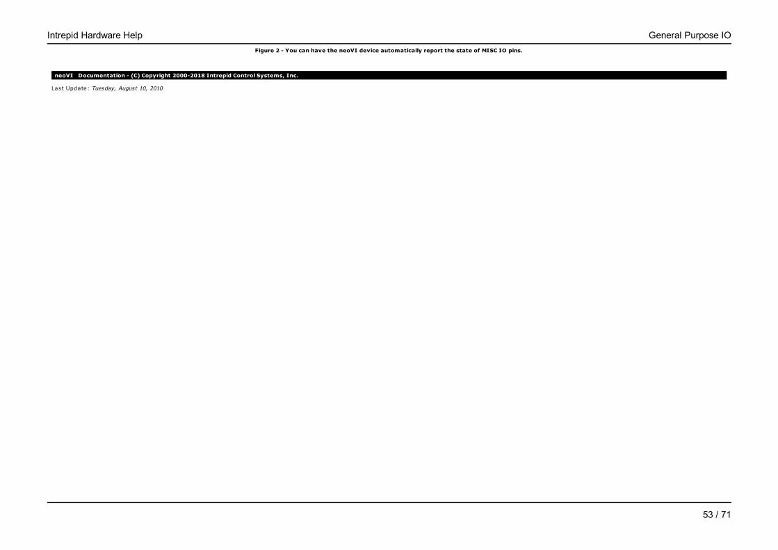
Figure 2 - You can have the neoVI device automatically report the state of MISC IO pins.
neoVI Documentation - (C) Copyright 2000-2018 Intrepid Control Systems, Inc.
Last Update: Tuesday, August 10, 2010
Intrepid Hardware Help General Purpose IO
53 / 71
Specifications - neoVIMain
Applies to neoVI FIRE
Device
Device Specifications• neoVI 3G Architecture over 10x performance over previous devices• 3 DSPs and 1 RISC processor for 125 MIPS of processing• Power Consumption (typical) : 150mA @ 14.4 VDC• Sleep Power Consumption (typical) : 12mA @ 12.0 VDC• Power Supply: 4.5-27 Volt Power Operation (Physical layers non functional under 5.5 volt)• Dual user notification LED (red and green)• Temperature Range: -40C to +85C • Vehicle Connectors : 25 Pin male D-SUB and 9 Pin Male D-SUB• Warranty: One Year Lim ited Warranty• Firmware: Fie ld upgradeable design (flash firmware)• General Purpose IO: 6 MISC IO (0 - 3.3V), 4 IO can be configured as analog• General Purpose IO rate report interval: 10 Hz to 1 Khz or based on digital change• Microsoft Certified USB drivers• Isolated USB• Stand-Alone Mode Including Scripting, Receive Messages, Transmit Messages, Expressions, IO, and Transport Layers• J2534 and RP1210 A/B compatible for CAN/ISO15765, Keyword, ISO9141, and J1850 VPW• microSD card slot support for up to 16 Gigabytes of storage (or up to the lim it of newer SDHC cards). The removable card is formatted using FAT32 for direct usage in a PC.• Battery backed real time clock (RTC)
Networks - General• 64 Bit time stamping to accuracy of 10 m icroseconds on CAN and LIN networks and never overflows. 0.5 m icrosecond accuracy timestamp available if using one network only• Simultaneous operations on all CAN/LIN/J1850 networks• Transmit message double-buffering on all networks allows back to back message transmission
Network Specifications6x CAN Channels• 4 Dedicated ISO11898 Dual Wire CAN Physical Layer (TJA1040)• 1 Dedicated ISO11519 Low Speed Fault Tolerant CAN Physical Layer (TJA1054A) • 1 Dedicated Single Wire CAN Physical Layer GMW3089 / SAE J2411 (MC33897)• CAN 2.0B Active• Up to 1 M-Bit Software Selectable Baud Rate (auto baud capable)• Capable of generating and detecting error frames (With firmware update)• Logic Analysis of CAN Waveform with 25 nanosecond resolution (With firmware update)• Graphical Bit Time / Baud Rate Calculator• Listen only mode support• Unterminated network detection (With firmware update)• High Speed Mode, Test Tool Resistor, and High Voltage Wakeup support
4x LIN (Local Interconnect), ISO9141, Keyword 2000, or K and L Line
• Full support for LIN 1.X, 2.X and J2602• LIN J2602 / 2.X compatible physical layer• Software enabled 1K LIN Master Resistor PER CHANNEL • Capable of Generating LIN Waveforms (Including Errors) Using Dedicated Output Compare Hardware (With firmware update)• LIN Bus Monitor Mode identifies errors: Sync Break Error State and Length, Sync Wave Error, Message ID parity, TFrameMax/Slave Not Responding, Checksum Error and Transmit Bit Errors.• LIN Bus Master Mode operates at same time as LIN Bus Monitor• LIN Bus Slave simulation - with or without an LDF file• LIN Bus hardware schedule table with support for LIN diagnostics• UART Based State Machine• only first channel supports L• Programmable Tim ing Parameters including Inter-Byte, TX Inter-Frame, RX Inter-Frame and Initia lization Waveforms (0.5 ms Resolution)• Initia lization Waveforms including Fast Init, Five Baud, and Custom• Software Selectable Baud Rate• Software enabled 512K Resistor (channel one only)
1x J1850 VPW (GM Class 2)• VPW Physical Layer capable of TX and RX operations (MC33390)• Reception of IFR data during TX and RX
1x GM CGI• Software Enabled (disables LIN2)• Programmable Bit Rate (625K, 115.2K, others)• Full block mode message reception only
Intrepid Hardware Help Specifications
54 / 71
• Transmission Option available in CGI Simulation Toolk it
neoVI Documentation - (C) Copyright 2000-2018 Intrepid Control Systems, Inc.
Last Update: Monday, December 14, 2009
Intrepid Hardware Help Specifications
55 / 71
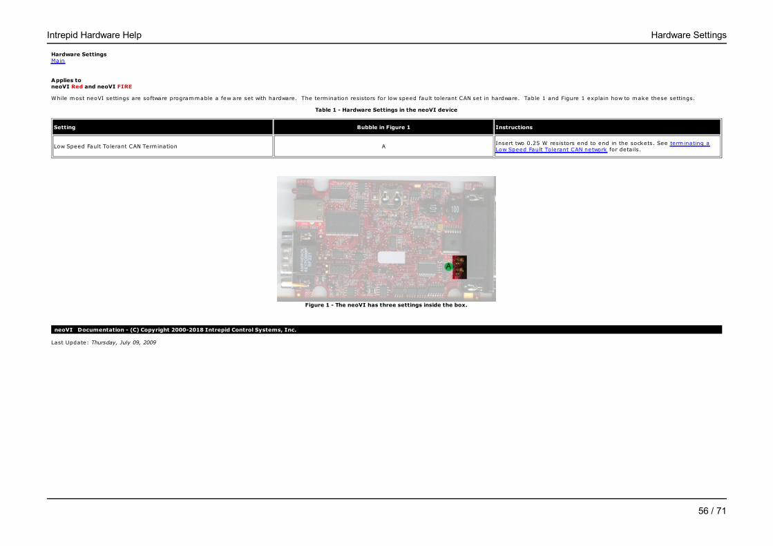
Hardware Settings Main
Applies to neoVI Red and neoVI FIRE
While most neoVI settings are software programmable a few are set with hardware. The term ination resistors for low speed fault tolerant CAN set in hardware. Table 1 and Figure 1 explain how to make these settings.
Table 1 - Hardware Settings in the neoVI device
Setting Bubble in Figure 1 Instructions
Low Speed Fault Tolerant CAN Termination AInsert two 0.25 W resistors end to end in the sockets. See term inating aLow Speed Fault Tolerant CAN network for details.
Figure 1 - The neoVI has three settings inside the box.
neoVI Documentation - (C) Copyright 2000-2018 Intrepid Control Systems, Inc.
Last Update: Thursday, July 09, 2009
Intrepid Hardware Help Hardware Settings
56 / 71

LED Blinking patternsMain
Applies to neoVI Red, neoVI FIRE, and neoVI Yellow
neoVI has 2 LEDs used to report the status of the device. The LEDs on the neoVI can also be control through a script, Vehicle Spy, or custom application. The table below explains and shows the common blink ing patterns thedevice can exhibit.
Name Image Pattern Description
Powered, not running CoreMini Flashing Green This blinking sequence occurs when the device is powered and is not running a CoreMini Script.
PC Mode Flashing Red, Green When Vehicle Spy 3 or other PC based program is connected to the neoVI, the LEDs will alternate Red, Green. Keep in mind that scripts running in VehicleSpy 3 can change the blinking pattern of the device.
CoreMini Mode Flashing Red This is the default blinking pattern when running a CoreMini Script. Keep in mind that the blinking pattern can be changed by VehicleScape Logging or in afunction block.
VehicleScape Standalone Logging Flashing Red. Green blinking. VehicleScape Standalone loggings changes the blinking pattern of the LEDs. The Red LED will flash at a constant rate while the Green will blink with databeing saved to Micro SD card.
VehicleScape Standalone Logging, Post trigger Flashing Red, quickly blinkingGreen
This pattern appears when working with pre/post triggers in VehicleScape Standalone loggings. The Red LED will flash at a constant rate while the Green willblink at a fast rate with data being saved to Micro SD card for the post collection.
Boot loader 3x Green, Red A pattern of Green, Green, Green, Red denotes boot loader mode. This mode is corrected by connecting to Vehicle Spy 3 or an application that can use thehardware. This is a normal blinking pattern.
Table 1 - LED Blinking for neoVI FIRE, neoVI Red, and neoVI Yellow
neoVI Documentation - (C) Copyright 2000-2018 Intrepid Control Systems, Inc.
Intrepid Hardware Help LED Blinking
57 / 71

Last Update: Friday, September 13, 2013
Intrepid Hardware Help LED Blinking
58 / 71
Hardware Features - neoVIMain
Applies to neoVI Yellow
The neoVI device has many configurable features which are not in-vehicle networks. The hardware features discussed in this section include the following: 1) General Purpose IO and 2) Specifications.
neoVI Documentation - (C) Copyright 2000-2018 Intrepid Control Systems, Inc.
Last Update: Wednesday, July 15, 2009
Intrepid Hardware Help neoVI Yellow
59 / 71
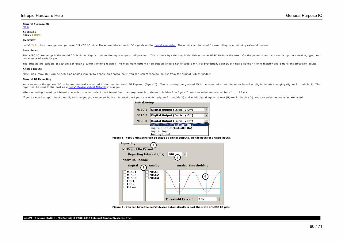
General Purpose IO Main
Applies to neoVI Yellow
Overview
neoVI Yellow has three general purpose 3.3 VDC IO pins. These are labeled as MISC signals on the neoVI connector. These pins can be used for controlling or monitoring external devices.
Basic Setup
The MISC IO are setup in the neoVI 3G Explorer. Figure 1 shows the input output configuration. This is done by selecting Initia l Values under MISC IO from the tree. On the panel shown, you can setup the direction, type, andinitia l state of each IO pin.
The outputs are capable of LED drive through a current lim iting resistor. The maximum current of all outputs should not exceed 5 mA. For protection, each IO pin has a series 47 ohm resistor and a transient protection device.
Analog Inputs
MISC pins through 3 can be setup as analog inputs. To enable an analog input, you can select "Analog inputs" from the "Initia l Setup" window.
General IO Reporting
You can setup the general IO to be automatically reported to the host in neoVI 3G Explorer (figure 2). You can setup the general IO to be reported at an interval or based on digital inputs changing (figure 2 : bubble 1). Thereport will be sent to the host as a neoVI Device Virtual Network message.
When reporting based on interval is selected you can select the interval from the drop down box shown in bubble 2 in figure 2. You can select an interval from 1 to 125 ms.
If you selected a report based on digital change, you can select both an interval the inputs are tested (figure 2 : bubble 2) and which digital inputs to test (figure 2 : bubble 3). You can select as many as are listed.
Figure 1 - neoVI MISC pins can be setup as digital outputs, digital inputs or analog inputs.
Figure 2 - You can have the neoVI device automatically report the state of MISC IO pins.
neoVI Documentation - (C) Copyright 2000-2018 Intrepid Control Systems, Inc.
Intrepid Hardware Help General Purpose IO
60 / 71

Last Update: Tuesday, January 08, 2013
Intrepid Hardware Help General Purpose IO
61 / 71

Specifications Main
Applies to neoVI Yellow
Device Specifications• 2 DSPs and 1 RISC processor for 88 MIPS of processing• 1 MB message buffer* Power Consumption (typical) : 100mA @ 14.4 VDC• Sleep Power Consumption (typical) : 8mA @ 12.0 VDC• Power Supply: 5.5-32 Volt Power Operation• Temperature Range: -40C to +85C• Vehicle Connectors : 15 Pin male D-SUB• General Purpose IO: 3 MISC IO (0 - 3.3V)• General Purpose IO rate report interval: 1 Hz to 10 Khz or based on digital change• Microsoft© Certified USB drivers• Isolated USB 2.0 Full Speed Device backward compatible with USB1.1• Stand-Alone Mode Including Scripting, Receive Messages, Transmit Messages, Expressions, IO, and Transport Layers• RS232 host port with HW handshaking support for scripting and gatewaying network data• ICS TimeSync for Multiple Hardware Synchronization supports all neoVI 3G devices• J2534 and RP1210 A/B compatible for CAN/ISO15765, J1708, Keyword, and ISO9141• m icroSD card slot support up to 12 Gigabytes of storage. The removable card is formatted using FAT32 for direct usage in a PC.• Battery backed real-time clock (RTC)• Warranty: One Year Lim ited Warranty• Firmware: Fie ld upgradeable design (flash firmware)
Networks - General• 64 Bit time stamping to accuracy of 10 m icroseconds on networks and never overflows. 0.5 m icrosecond accuracy timestamp available if using one network only• Simultaneous operations on all networks• Transmit message double-buffering on all networks allows back to back message transmission
Network Specifications2x J1939/CAN Channels• 2 Dedicated ISO11898 Dual Wire CAN Physical Layer (TJA1040)• CAN 2.0B Active• Up to 1 M-Bit Software Selectable Baud Rate (auto baud capable)• Capable of generating and detecting error frames• Logic Analysis of CAN Waveform with 25 nanosecond resolution• Graphical Bit Time / Baud Rate Calculator• Listen only mode support* Unterminated network detection
J1708• High precision time capture of J1708 bus events• Software selectable parameters including baud rate• SAE J1708 Physical layer
K and L Line, 1x LIN (Local Interconnect), ISO9141, or Keyword 2000• UART Based State Machine• Initia lization Waveforms including Fast Init, Five Baud, and Custom• Programmable Tim ing Parameters including Inter-Byte, TX Inter-Frame, RX Inter-Frame and Initia lization Waveforms (0.5 ms Resolution) Full support for LIN 1.X, 2.X and J2602• K and L have software controlled transmit enable lines allowing many different variants of UART or ISO9141 communications including:Tx on L Rx on K (full duplex);Tx and Rx on K (half duplex);Tx on K and L and Rx on K• Socket selectable pull up resistor on both K and L lines• Capable of Generating LIN Waveforms (Including Errors) Using Dedicated Output Compare Hardware• Software Selectable Baud Rate• LIN Bus Monitor Mode identifies errors : Sync Break Error State and Length, Sync Wave Error, Message ID parity, TFrameMax/Slave Not Responding, Checksum Error and Transmit Bit Errors.• LIN Bus Master Mode operates at same time as LIN Bus Monitor• LIN Bus Slave simulation - with or without an LDF file• LIN Bus hardware schedule table with support for LIN diagnostics GM Class 2/ SAE J1850 VPW• VPW Physical Layer capable ofTx and Rx operations in high speed modes (MC33390)• Reception of IFR data during rx and tx• Long Message transmit and reception for ECU flashing
neoVI Documentation - (C) Copyright 2000-2018 Intrepid Control Systems, Inc.
Last Update: Tuesday, January 08, 2013
Intrepid Hardware Help Specifications
62 / 71

Hardware Settings Main
Applies to neoVI Yellow
While most neoVI settings are software programmable a few are set with hardware. The pull up resistors for the UART/ISO/Keyword 2k network
Table 1 - Hardware Settings in the neoVI device
Setting Bubble in Figure 1 Instructions
K and L line pull-up resistors AInsert two 0.25 W resistors end to end with desired pull up values (510Ohms are the factory default)
Figure 1 - The K-Line pull-ups.
neoVI Documentation - (C) Copyright 2000-2018 Intrepid Control Systems, Inc.
Last Update: Thursday, July 09, 2009
Intrepid Hardware Help Hardware Settings
63 / 71
Hardware Features Main
Applies to ValueCAN 3
The ValueCAN 3 has few configurable features which are not in-vehicle network. The General Purpose IO and Specifications sections cover the non network features.
neoVI Documentation - (C) Copyright 2000-2018 Intrepid Control Systems, Inc.
Last Update: Wednesday, July 15, 2009
Intrepid Hardware Help ValueCAN 3
64 / 71

Intrepid Hardware Help General Purpose IO
65 / 71

Intrepid Hardware Help Specifications
66 / 71

Related Info - neoVIMain
The topic of in-vehicle networks can be a complex one. This section details some resources to help learn more about them. The resources are the following: 1) SAE OBD Book, 2) Internet Resources and 3) Glossary.
neoVI Documentation - (C) Copyright 2000-2018 Intrepid Control Systems, Inc.
Last Update: Wednesday, April 11, 2001
Intrepid Hardware Help Related Info
67 / 71

SAE OBD Book - neoVIMain
SAE On-Board Diagnostics for Light and Medium Duty Vehicles Standards Manual 1999 Edition
Edition: 1
Contents include: Electrical/Electronic Systems Diagnostic Terms, Definitions, Abbreviations and Acronyms; Diagnostic Connector; OBD II Scan Tool; E/E Diagnostic Test Modes; Recommended Practice for Diagnostic Trouble CodeDefinitions; E/E Data Link Security; Enhanced E/E Diagnostic Test Modes; Class B Communications Network Interface; Class B Data Communication Network Messages - Detailed Header Formats Physical Address Assignments;Class B Data Communication Network Messages - Part 2: Data Parameter Definitions; Class B Data Communication Network Messages - Part 3: Frame IDs for Single Byte Forms of Headers; Class B Data CommunicationNetwork Messages - Message Definitions for Three Byte Headers; and Bibliography of Related SAE Technical Papers.
This book contains all of the following specifications: J1850, J1962, J1979 and other diagnostic specifications.
ISBN Number: 0-7680-0337-7Date Published: June 1999408 PagesBinding: PaperboundProduct Code: HS-3000/99
Purchase from the SAE website (http://www.sae.org). Search on HS-3000 as there may be updates.
neoVI Documentation - (C) Copyright 2000-2018 Intrepid Control Systems, Inc.
Last Update: Sunday, April 22, 2001
Intrepid Hardware Help SAE OBD Book
68 / 71
Internet Resources - neoVIMain
Intrepid Control Systems, Inc. Sites
Main Website www.intrepidcs.com
neoVI Website www.intrepidcs.com/neovi/
Vehicle Spy Website www.intrepidcs.com/vspy/
In-vehicle Network Specifications
SAE (Society of Automotive Engineers) J1850, J1708, J1939, J1979, J1962, etc. : www.sae.org
LIN (Local Interconnect Network) : www.lin-subbus.org
Bosch (Controller Area Network Specification) : www.can.bosch.com
ISO (International Organization fro Standardization) www.iso.ch
US EPA OBD-II Site www.epa.gov/oms/obd.htm
CARB (California Air Resources Board) www.arb.ca.gov
neoVI Silicon Vendors
Microchip Technology : MCP2510 CAN Controller www.microchip.com
Philips : Dual Wire (82C251) and Low Speed Fault Tolerant (TJA1054) Transceivers www.philips.com
Infineon : Single Wire CAN Transceiver TLE6255 www.infineon.com
Motorola : J1850 VPW Physical Layer MC33390 Transceiver and LBCC Ford SCP Communications IC www.mot-sps.com
neoVI Documentation - (C) Copyright 2000-2018 Intrepid Control Systems, Inc.
Last Update: Tuesday, March 26, 2002
Intrepid Hardware Help Internet Resources
69 / 71

Glossary - neoVIMain
ALDL - Assembly Line Data Link - The pre-OBD-II communications link found on GM vehicles.
Arbitration ID (Arb ID) - The identifier portion of the CAN (Controller Area Network) message.
CARB - California Air Resources Board - Agency in California which sets emission standards which re late to OBD.
CAN - Controller Area Network - A vehicle network which has messages which contain an Arbitration ID (Arb ID) fie ld, a DLC data length code fie ld and an eight byte data fie ld. The Arb ID can be 11 bits or 29 bits. Thisspecification was re leased by Bosch.
Class 2 - General Motors messaging strategy based on the VPW part of the J1850 specification.
Ford SCP - Ford Motor Company messaging strategy based on the PWM part of the J1850 specification
GMLAN - General Motors messaging strategy using CAN. This strategy is planned to replace the Class 2 messaging strategy (J1850).
IDB - Infotainment data bus - Different specifications re lated to in-vehicle information and entertainment data buses. IDB-C is a specification that uses dual wire CAN.
ISO9141 - A UART based protocol which is allowed under OBD-II.
J1587 - Standard which defines messaging packets for J1708 physical layer networks.
J1708 - Physical Layer specification and Protocol for using a RS485 style network. Used in truck and bus applications.
J1850 - Physical Layer and Protocol specification for north American in-vehicle communications. It consists of two physical layers VPW and PWM which share sim ilar data formats. This includes a 11 byte message with a CRC. In-frame responses are also available in the protocol.
J1939 - Specification for communications for Heavy Truck and Bus based on CAN messages using a 29 bit Arb ID.
J1962 - Specification detailing the diagnostic connector found in North American vehicles. This connector is also called the ODB-II connector and the ALDL connector.
J1979 - Specifications which detail ODB-II test modes and data. This includes requesting values from the Vehicle such as RPM, Engine Load, Coolant Temp, Vehicle Speed, Etc.
Keyword 2000 - An enhanced version of ISO9141 which specifies many diagnostics services.
LIN - Local Interconnect Network - A UART based network which consist of a master and many slave nodes.
Messaging Strategy - This is a higher-level protocol which defines how the content of vehicle network messages is used and when messages are transmitted.
OBD - On-board Diagnostics - Software inside the Vehicle which automatically diagnoses the Vehicle. OBD-II specifies diagnostics services required by law in North America.
Physical Layer - The electrical signaling portion of a protocol.
PWM - Pulse Width Modulation - This type of e lectrical coding is used in the J1850 spec PWM protocol.
RS232 - PC communication port which can operate at speeds between 300 and 115k bits per second.
SAE - Society of Automotive Engineers (www.sae.org)
UART - Universal Asynchronous Receiver Transmitter - A network protocol based on a UART found on many microcontrollers.
USB - Universal Serial Bus - A 12 megabits per second bus communication port.
VPW - Variable Pulse Width - This type of e lectrical coding is used in the J1850 spec VPW protocol.
neoVI Documentation - (C) Copyright 2000-2018 Intrepid Control Systems, Inc.
Last Update: Wednesday, April 11, 2001
Intrepid Hardware Help Glossary
70 / 71
Contact Information
Intrepid Control Systems, Inc.31601 Research Park Dr.Madison Heights, MI 48071 USA(ph) 586.731.7950(fax) 586.731.2274(email)
(website) www.intrepidcs.com
neoVI Documentation - (C) Copyright 2000-2018 Intrepid Control Systems, Inc.
Last Update: Monday, September 16, 2013
Intrepid Hardware Help Contact
71 / 71