user and maintenance manual - … manual.pdf · 1 purestream cwt user and maintenence manual.doc...
TRANSCRIPT
1
Purestream CWT User and Maintenence Manual.doc July 2013
USER AND MAINTENANCE MANUAL
Air cooled liquid chillers
R410A refrigerant Cooling capacity 2.1 – 32.2 Tons, scroll and rotary compressors
60 Hz
Dear Customer,
Thank you for the trust you have placed in us. Please read this manual carefully to obtain the best
performance from our product.
In order to avoid incorrect operating conditions and danger for the operators, it is essential that you
follow the directions meticulously as well as the current accident-prevention laws in the country of
use.
Each CWT chiller is rigorously tested before being packed.
This verifies that there are no manufacturing defects and that the machine performs correctly the
functions for which it was designed.
This manual must be kept for future reference and is an integral part of the chiller you have
purchased.
Due to continuous technical development, we reserve the right to make the necessary modifications
without any obligation to give advance notice.
Do not hesitate to contact us if you have any problems or need more information.
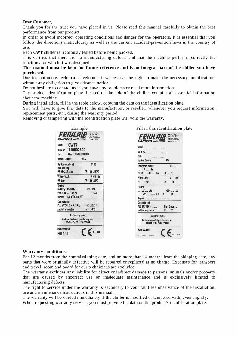
The product identification plate, located on the side of the chiller, contains all essential information
about the machine.
During installation, fill in the table below, copying the data on the identification plate.
You will have to give this data to the manufacturer, or reseller, whenever you request informati on,
replacement parts, etc., during the warranty period.
Removing or tampering with the identification plate will void the warranty.
Example Fill in this identification plate
Warranty conditions: For 12 months from the commissioning date, and no more than 14 months from the shipping date, any
parts that were originally defective will be repaired or replaced at no charge. Expenses for transport
and travel, room and board for our technicians are excluded.
The warranty excludes any liability for direct or indirect damage to persons, animals and/or property
that are caused by incorrect use or inadequate maintenance and is exclusively limited to
manufacturing defects.
The right to service under the warranty is secondary to your faultless observance of the installation,
use and maintenance instructions in this manual.
The warranty will be voided immediately if the chiller is modified or tampered with, even slightly.
When requesting warranty service, you must provide the data on the product's identification plate.

CONTENTS
1 SAFETY RULES ............................................................................................................ 1
1.1 Definitions of the symbols used ........................................................................................ 1 1.2 Warnings .......................................................................................................................... 2 1.3 Proper use of the chiller .................................................................................................... 2 1.4 Instructions for using equipment under pressure conforming to PED Directive 2014/68/EU 3
2 OPERATION AND MAIN COMPONENTS ................................................................... 4
2.1 Refrigerant circuit .............................................................................................................. 4 2.2 Water circuit ...................................................................................................................... 4 2.3 Fans ................................................................................................................................. 5 2.4 Condensation control ........................................................................................................ 5 2.5 Control of the water temperature....................................................................................... 5 2.6 Protecting the integrity of the machine .............................................................................. 5 2.7 CWT units: identification of the main components ............................................................. 6
2.7.1 TA version – Open circuit kit with additional water tank ................................................... 6
2.7.2 BA version – Automatic water bypass valve ....................................................................... 6
2.8 Spare parts ....................................................................................................................... 8
3 INSTALLATION ............................................................................................................. 9
3.1 Transport .......................................................................................................................... 9 3.1.1 Handling the unit with a forklift truck or pallet jack ............................................................. 9
3.1.2 Lifting with belts and tubes .................................................................................................... 9
3.2 Storage ........................................................................................................................... 10 3.3 Place of installation ......................................................................................................... 10
3.3.1 Installation spaces ................................................................................................................ 10
3.4 Water connections .......................................................................................................... 11 3.4.1 Recommended water system ............................................................................................. 11
3.4.2 Use of ethylene glycol as a winter anti-freeze .................................................................. 12
3.4.3 Charging the water circuit .................................................................................................... 13
3.5 Electrical connections ..................................................................................................... 13 3.5.1 Connecting a remote on/off switch and a remote alarm indicator light ......................... 14
4 PRELIMINARY CHECKS AND START-UP ............................................................... 15
4.1 Preliminary checks and preparation for the first start-up ................................................. 15 4.2 Start-up ........................................................................................................................... 15
4.2.1 Start-up under critical conditions ........................................................................................ 16
4.3 Turning off the unit .......................................................................................................... 16
5 ELECTRONIC CONTROLLER ................................................................................... 17
5.1 Main functions of the electronic controller buttons and meanings of the icons ................ 18 5.2 Turning on and off ........................................................................................................... 18 5.3 Water temperature: dead-zone regulation ....................................................................... 19 5.4 Changing the set point ................................................................................................... 19 5.5 Changing the type of restart after a power failure ............................................................ 20 5.6 Changing the serial address (MODBUS and CAN) ......................................................... 20 5.7 Display of inputs and outputs ......................................................................................... 20 5.8 Displaying the software release version of the electronic controller................................. 22 5.9 Displaying the compressor and pump counters............................................................... 22 5.10 Alarms ............................................................................................................................ 22
5.10.1 Displaying and resetting alarms ......................................................................................... 22
5.10.2 Displaying of alarm history .................................................................................................. 22
5.10.3 Table of alarm codes ............................................................................................................ 23
6 SAFETY DEVICES ...................................................................................................... 24
6.1 Calibration of the safety devices and type of rearm ......................................................... 24 6.2 Resetting the high-pressure pressure switch .................................................................. 25
7 OPERATING LIMITS ................................................................................................... 26
7.1 Minimum water flow ........................................................................................................ 27 7.2 Low water temperatures (<32°F//0°C) ............................................................................. 27
7.2.1 Changing the setting of the anti-freeze thermostat and relative parameter ................. 27
8 MAINTENANCE AND INSPECTIONS AND PERIODIC CHECKS ........................... 29
9 TROUBLESHOOTING ................................................................................................ 30
10 DISMANTLING THE CHILLER ................................................................................... 33
11 WATER DIAGRAMS ................................................................................................... 34
12 REFRIGERANT CIRCUITS DIAGRAMS ................................................................... 35
13 DIMENSIONAL DRAWINGS ...................................................................................... 38

1 7425MUM571 Model: CWT - Use and Maintenance Manual Rev. 05
1
SAFETY RULES
1.1 DEFINITIONS OF THE SYMBOLS USED
Read this use and maintenance manual carefully before performing any repairs on the chiller.
Warnings of a general character; risk of danger or possibility of damaging the machine, pay particular attention to the phrase following this symbol.
Risk of electrical danger; the phrase highlights conditions that could be fatal. Follow the instructions provided meticulously.
Risk of danger; component or system under pressure.
Risk of danger; component or system that can reach high temperatures during operation.
Risk of danger; it is absolutely forbidden to use water to extinguish fires near or on the chiller.
Risk of danger; it is absolutely forbidden to operate the machine with the panel open.
Service that can be performed by the machine’s operator, if qualified (1).
Water input connection point.
Water output connection point.
Dispose of each type of material in accordance with the requirements of the country of
use.
NOTE Phrases to be emphasized that do not contain safety rules.
2 7425MUM571 Model: CWT - Use and Maintenance Manual Rev. 05
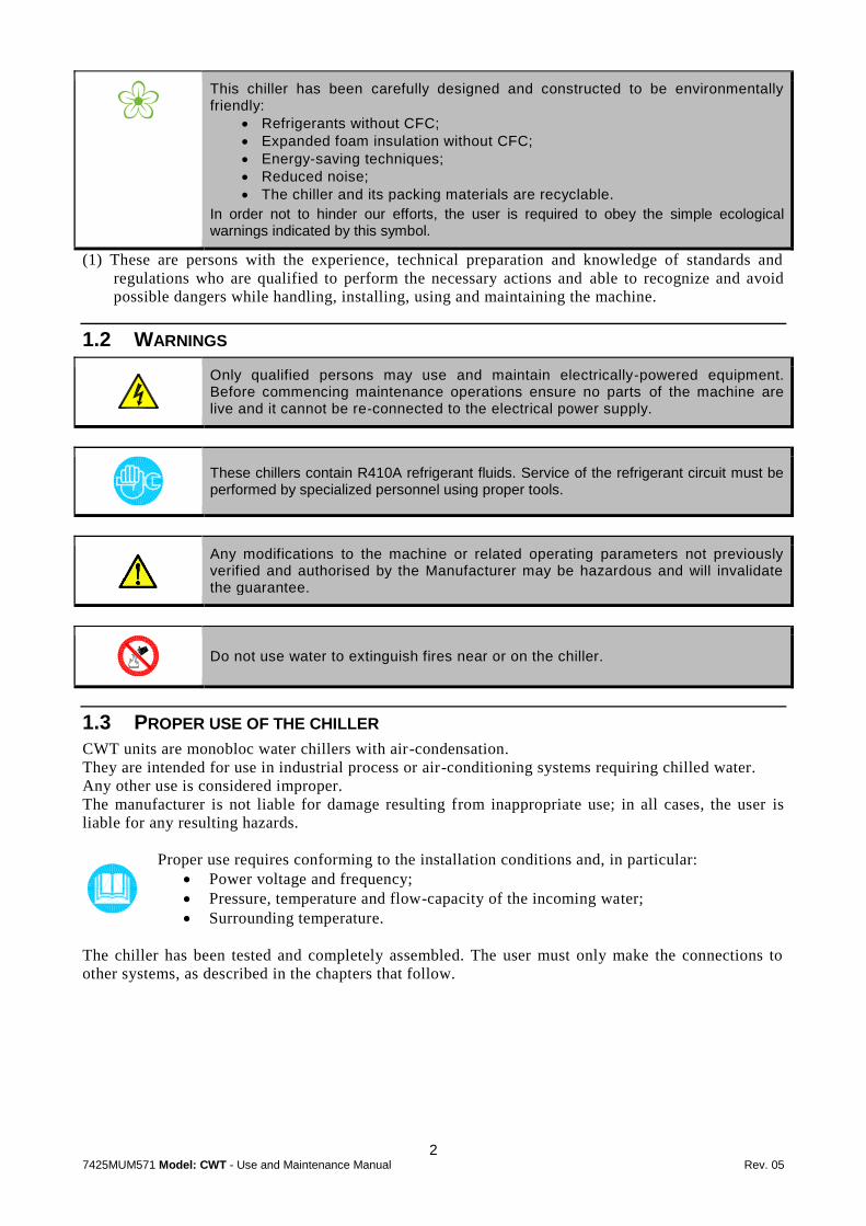
This chiller has been carefully designed and constructed to be environmentally friendly:
Refrigerants without CFC;
Expanded foam insulation without CFC;
Energy-saving techniques;
Reduced noise;
The chiller and its packing materials are recyclable.
In order not to hinder our efforts, the user is required to obey the simple ecological warnings indicated by this symbol.
(1) These are persons with the experience, technical preparation and knowledge of standards and
regulations who are qualified to perform the necessary actions and able to recognize and avoid
possible dangers while handling, installing, using and maintaining the machine.
1.2 WARNINGS
Only qualified persons may use and maintain electrically-powered equipment. Before commencing maintenance operations ensure no parts of the machine are live and it cannot be re-connected to the electrical power supply.
These chillers contain R410A refrigerant fluids. Service of the refrigerant circuit must be performed by specialized personnel using proper tools.
Any modifications to the machine or related operating parameters not previously verified and authorised by the Manufacturer may be hazardous and will invalidate the guarantee.
Do not use water to extinguish fires near or on the chiller.
1.3 PROPER USE OF THE CHILLER
CWT units are monobloc water chillers with air-condensation.
They are intended for use in industrial process or air-conditioning systems requiring chilled water.
Any other use is considered improper.
The manufacturer is not liable for damage resulting from inappropriate use; in all cases, the user is
liable for any resulting hazards.
Proper use requires conforming to the installation conditions and, in particular:
Power voltage and frequency;
Pressure, temperature and flow-capacity of the incoming water;
Surrounding temperature.
The chiller has been tested and completely assembled. The user must only make the connections to
other systems, as described in the chapters that follow.

3 7425MUM571 Model: CWT - Use and Maintenance Manual Rev. 05
1.4 INSTRUCTIONS FOR USING EQUIPMENT UNDER PRESSURE CONFORMING TO
PED DIRECTIVE 2014/68/EU
The proper use of equipment under pressure is an essential prerequisite for ensuring safety.
To this end, the user must proceed as follows:
Use the equipment properly within the temperature limits shown in the operating limits stated
on the manufacturer’s name/data plate;
Do not solder on the exchangers or refrigerant fluid pipes;
Do not install the equipment in insufficiently ventilated rooms, areas exposed to sources of
heat or near inflammable substances;
During operation, the equipment must not be subjected to vibrations that could cause fatigue
failures;
Keep the documentation attached to the equipment (user manual, declaration of conformity,
etc.) for future reference;
The maximum working pressure stated on the manufacturer’s data plate must not be exceeded.
Prior to use, the user must fit safety/pressure relief devices.
4 7425MUM571 Model: CWT - Use and Maintenance Manual Rev. 05
2
OPERATION AND MAIN COMPONENTS
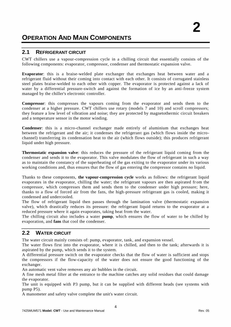
2.1 REFRIGERANT CIRCUIT
CWT chillers use a vapour-compression cycle in a chilling circuit that essentially consists of the
following components: evaporator, compressor, condenser and thermostatic expansion valve.
Evaporator: this is a braise-welded plate exchanger that exchanges heat between water and a
refrigerant fluid without their coming into contact with each other. It consists of corrugated stainless
steel plates braise-welded to each other with copper. The evaporator is protected against a lack of
water by a differential pressure-switch and against the formation of ice by an anti-freeze system
managed by the chiller's electronic controller.
Compressor: this compresses the vapours coming from the evaporator and sends them to the
condenser at a higher pressure. CWT chillers use rotary (models 7 and 10) and scroll compressors;
they feature a low level of vibration and noise; they are protected by magnetothermic circuit breakers
and a temperature sensor in the motor winding.
Condenser: this is a micro-channel exchanger made entirely of aluminium that exchanges heat
between the refrigerant and the air; it condenses the refrigerant gas (which flows inside the micro-
channel) transferring its condensation heat to the air (which flows outside); this produces refrigerant
liquid under high pressure.
Thermostatic expansion valve: this reduces the pressure of the refrigerant liquid coming from the
condenser and sends it to the evaporator. This valve modulates the flow of refrigerant in such a way
as to maintain the constancy of the superheating of the gas exiting to the evaporator under its various
working conditions and, thus ensures that the flow of gas entering the compressor contains no liquid.
Thanks to these components, the vapour-compression cycle works as follows: the refrigerant liquid
evaporates in the evaporator, chilling the water; the refrigerant vapours are then aspirated fr om the
compressor, which compresses them and sends them to the condenser under high pressure; here,
thanks to a flow of forced air from the fans, the high-pressure refrigerant gas is cooled, making it
condensed and undercooled.
The flow of refrigerant liquid then passes through the lamination valve (thermostatic expansion
valve), which drastically reduces its pressure: the refrigerant liquid returns to the evaporator at a
reduced pressure where it again evaporates, taking heat from the water.
The chilling circuit also includes a water pump, which ensures the flow of water to be chilled by
evaporation, and fans that cool the condenser.
2.2 WATER CIRCUIT
The water circuit mainly consists of: pump, evaporator, tank, and expansion vessel.
The water flows first into the evaporator, where it is chilled, and then to the tank; afterwards it is
aspirated by the pump, which sends it to the system.
A differential pressure switch on the evaporator checks that the flow of water is sufficient and stops
the compressors if the flow-capacity of the water does not ensure the good functioning of the
exchanger.
An automatic vent valve removes any air bubbles in the circuit.
A fine mesh metal filter at the entrance to the machine catches any solid residues that could damage
the evaporator.
The unit is equipped with P3 pump, but it can be supplied with different heads (see systems with
pump P5).
A manometer and safety valve complete the unit's water circuit.

5 7425MUM571 Model: CWT - Use and Maintenance Manual Rev. 05
2.3 FANS
The fans force air through the condenser’s fins to remove the heat from the condensation of the
refrigerant gas, thus limiting the pressure inside the condenser.
CWT chillers use external-rotor axial fans with thermal protection inside the motor winding.
2.4 CONDENSATION CONTROL
When the temperature of the surrounding air drops, the cooling capacity of the air flow is significantly
increased, causing the pressure inside the condenser to drop; in order to keep this drop of the
condensation pressure from falling below the tolerable limit for the good functioning of the ch illing
circuit, the fans slow their rotation, reducing the flow of air.
The speed is controlled by an electronic regulator based on the condensation pressure; this allows the
machine to operate properly even when the temperature of the outside ai r is very low (see Chapter 7
Operating Limits) and also maintains a low level of noise with respect to its nominal operating
conditions.
2.5 CONTROL OF THE WATER TEMPERATURE
The purpose of the chiller is to maintain the temperature of the water produced within a des ired
interval as the load on the system varies; this is handled by an electronic controller and a temperature
probe that turn the compressors on and off appropriately (also see paragraph 5.3 Water
temperature: dead-zone regulation).
2.6 PROTECTING THE INTEGRITY OF THE MACHINE
In addition to controlling the temperature, the electronic controller uses pressure switches, thermostats
and timers to prevent and handle situations that could compromise the integrity of the machine (also
see Chapter 6 Safety Devices).
6 7425MUM571 Model: CWT - Use and Maintenance Manual Rev. 05
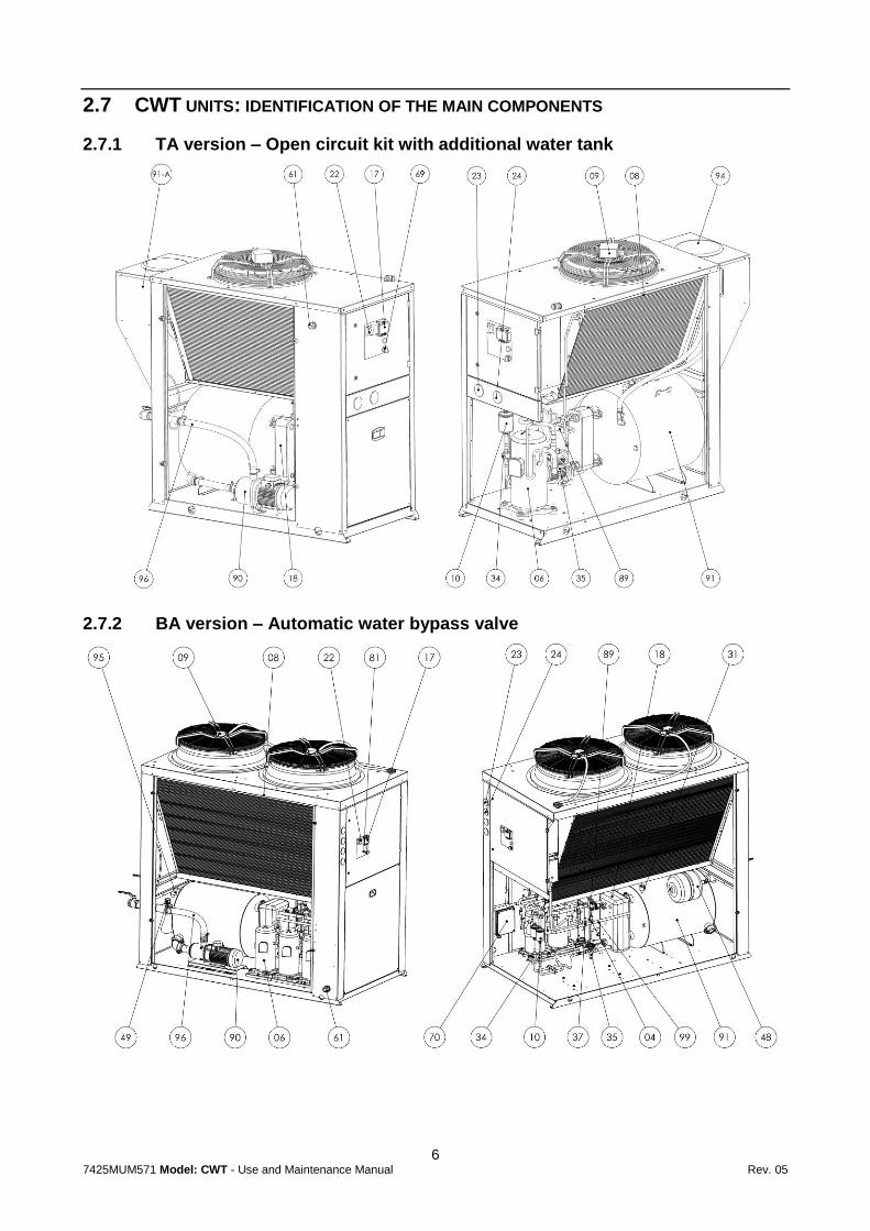
2.7 CWT UNITS: IDENTIFICATION OF THE MAIN COMPONENTS
2.7.1 TA version – Open circuit kit with additional water tank
2.7.2 BA version – Automatic water bypass valve

7 7425MUM571 Model: CWT - Use and Maintenance Manual Rev. 05
04 High pressure switch
06 Compressor
08 Condenser
09 Fan
10 Refrigerant filter
17 Electronic control
18 Evaporator
22 Disconnector switch
23 High pressure manometer
24 Low pressure manometer
31 Safety valve
34 Sight glass
35 Thermostatic expansion valve
37 Pressure transducer
48 Expansion vessel
49 Automatic water bypass valve
61 Power input
69 Selector 1/0/Remote
70 Fan speed regulator (Voltage regulator)
81 Refrigerant diagram
89 Differential pressure switch
90 Pump
91 Water tank
91-A Additional tank
94 Water filler
95 Inlet water
96 Outlet water
99 Pressure plug
8 7425MUM571 Model: CWT - Use and Maintenance Manual Rev. 05
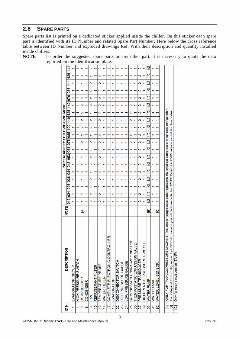
2.8 SPARE PARTS
Spare parts list is printed on a dedicated sticker applied inside the chiller. On this sticker each spare
part is identified with its ID Number and related Spare Part Number. Here below the cross reference
table between ID Number and exploded drawings Ref. With their description and quantity installed
inside chillers.
NOTE To order the suggested spare parts or any other part, it is necessary to quote the data
reported on the identification plate.
9 7425MUM571 Model: CWT - Use and Maintenance Manual Rev. 05
3
INSTALLATION
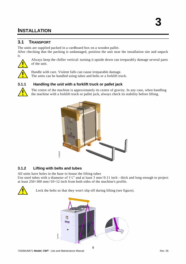
3.1 TRANSPORT
The units are supplied packed in a cardboard box on a wooden pallet.
After checking that the packing is undamaged, position the unit near the installation site and unpack
it.
Always keep the chiller vertical: turning it upside down can irreparably damage several parts
of the unit.
Handle with care. Violent falls can cause irreparable damage.
The units can be handled using tubes and belts or a forklift truck.
3.1.1 Handling the unit with a forklift truck or pallet jack
The centre of the machine is approximately its centre of gravity. In any case, when handling
the machine with a forklift truck or pallet jack, always check its stability before lifting.
3.1.2 Lifting with belts and tubes
All units have holes in the base to house the lifting tubes
Use steel tubes with a diameter of 1¼” and at least 3 mm//0.11 inch - thick and long enough to project
at least 250÷300 mm//10÷12 inch from both sides of the machine's profile.
Lock the belts so that they won't slip off during lifting (see figure).
10 7425MUM571 Model: CWT - Use and Maintenance Manual Rev. 05
3.2 STORAGE
Protect the machine from bad weather, even if packed.
Always keep the chiller vertical, even when in storage. Turning it upside down can irreparably
damage several parts of the unit.
If not used, the chiller can be stored packed in an enclosed place, free of dust, with a maximum
temperature of 50°C//122°F and specific humidity of no higher than 90%.
The packing material is recyclable.
Dispose of each type of material in accordance with the requirements in the country
of use.
3.3 PLACE OF INSTALLATION
The CWT unit can be installed either inside or outside.
To determine the best place to install the unit, it is important to consider the following aspects:
The dimensions and source of the water pipes;
The location of the electricity;
The solidity of the support surface;
Avoid any obstacles to the flow of the fan which could cause the recirculation of air to the
condenser;
Avoid the possible reflection of sound waves: (do not install in narrow or tight spaces);
Provide access for maintenance or repair (see paragraph 3.3.1 Installation spaces);
The air temperatures in the area selected for installation (see Chapter 7 Operating Limits).
Attention! If the machine is installed outside, it could find itself at a temperature lower than
0°C//32°F, when stopped; the formation of ice could damage the evaporator. If
you do not intend to drain the machine during the winter, you must add anti -
freeze to the water circuit (see paragraph 3.4.2 Use of ethylene glycol as a
winter anti-freeze).
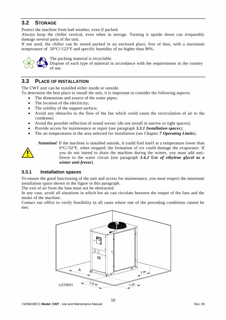
3.3.1 Installation spaces
To ensure the good functioning of the unit and access for maintenance, you must respect the minimum
installation space shown in the figure in this paragraph.
The exit of air from the fans must not be obstructed.
In any case, avoid all situations in which hot air can circulate between the output of the fans and the
intake of the machine.
Contact our office to verify feasibility in all cases where one of the preceding conditions cannot be
met.

11 7425MUM571 Model: CWT - Use and Maintenance Manual Rev. 05
Model A
CWT 007÷015 0.8 m // 32 inches (access for maintenance)
CWT 018÷150 1.5 m // 60 inches
3.4 WATER CONNECTIONS
Connect the machine to the water pipes following the instructions located near its water fittings (see
figures).
Water input to the machine
Water exit from the machine
Use the input and output taps provided with the machine: they allow the machine’s maintenance
without emptying the entire system or emptying the machine during the winter.
Important! Install the mechanical water filter, provided with the machine, on its input: scum
and impurities can seriously damage the evaporator.
Diameters of the water fittings
CWT models 007÷030 038÷065 075÷150
50 Hz 1” GAS FF 1½ ” GAS FF 2” GAS FF
60 Hz 1” NPT FF 1½ ” NPT FF 2” NPT FF
NOTE It is a good rule that the diameters of the arriving and departing pipes be not less than
the water fittings.
We recommend an extraordinary cleaning of the mechanical water filter after the machine
has been running for the first week (also see Chapter 8 Maintenance and periodic
inspections).
3.4.1 Recommended water system
The standard equipment provided with CWT units includes tank, pump, expansion vessel, safety
valve, filter, shut-off taps and automatic vent valve; however, we recommend that the water circuit
also be equipped with:
A mechanical filter and a check valve upstream from the charging tap;
An air vent at the highest point of the system;
A drain tap in the lowest point of the system;
Manometers and thermometers at the machine’s water input and output to check its
functioning;
Vibration damping joints on the pipes to avoid the transmission of vibration to the system.
In the case of water circuits with considerable capacity, we recommend checking whether it is
necessary to supplement the expansion vessel already on the unit with another additional one.
12 7425MUM571 Model: CWT - Use and Maintenance Manual Rev. 05
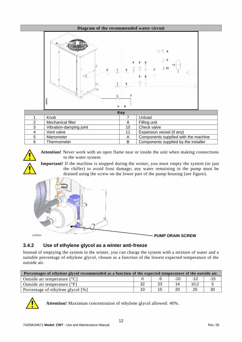
Diagram of the recommended water circuit
Key
1 Knob 7 Unload
2 Mechanical filter 8 Filling unit
3 Vibration-damping joint 10 Check valve
4 Vent valve 11 Expansion vessel (if any)
5 Manometer A Components supplied with the machine
6 Thermometer B Components supplied by the installer
Attention! Never work with an open flame near or inside the unit when making connections
to the water system.
Important! If the machine is stopped during the winter, you must empty the system (or just
the chiller) to avoid frost damage; any water remaining in the pump must be
drained using the screw on the lower part of the pump housing (see figure).
3.4.2 Use of ethylene glycol as a winter anti-freeze
Instead of emptying the system in the winter, you can charge the system with a mixture of water and a
suitable percentage of ethylene glycol, chosen as a function of the lowest expected temperature of the
outside air.
Percentages of ethylene glycol recommended as a function of the expected temperature of the outside air.
Outside air temperature [°C] 0 -5 -10 -12 -15
Outside air temperature [°F] 32 23 14 10,2 5
Percentage of ethylene glycol [%] 10 15 20 25 30
Attention! Maximum concentration of ethylene glycol allowed: 40%.
PUMP DRAIN SCREW
13 7425MUM571 Model: CWT - Use and Maintenance Manual Rev. 05
3.4.3 Charging the water circuit
Check that the drain taps are turned off;
Open all the system’s vent valves;
Turn on the system's shut-off devices;
Start filling by slowly turning on the system's water-charging tap;
When water starts coming out of the vent valves, close them and continue charging until the
manometer shows at least 1 bar;
Check for any leaks by looking at the manometer and inspecting the circuit.
3.5 ELECTRICAL CONNECTIONS
The machine must be connected to the electricity following the electrical diagram and
conforming to the current laws and regulations in the place of installation .
The voltage, frequency and number of phases must conform to the data shown on the
machine's identification plate;
The power supply voltage must not vary by more than ±10% from its nominal value;
The frequency must not vary by more than ±1% from its nominal value (±2% for brief
periods);
The imbalance between power phases must be <2%;
Upstream from the electrical panel, install a differential switch (IDn=0,03A) (main power
switch) and slow-blow fuses with the specifications shown on the electrical diagram and in the
following table;
Use wires of the section shown on the electrical diagram of the unit.
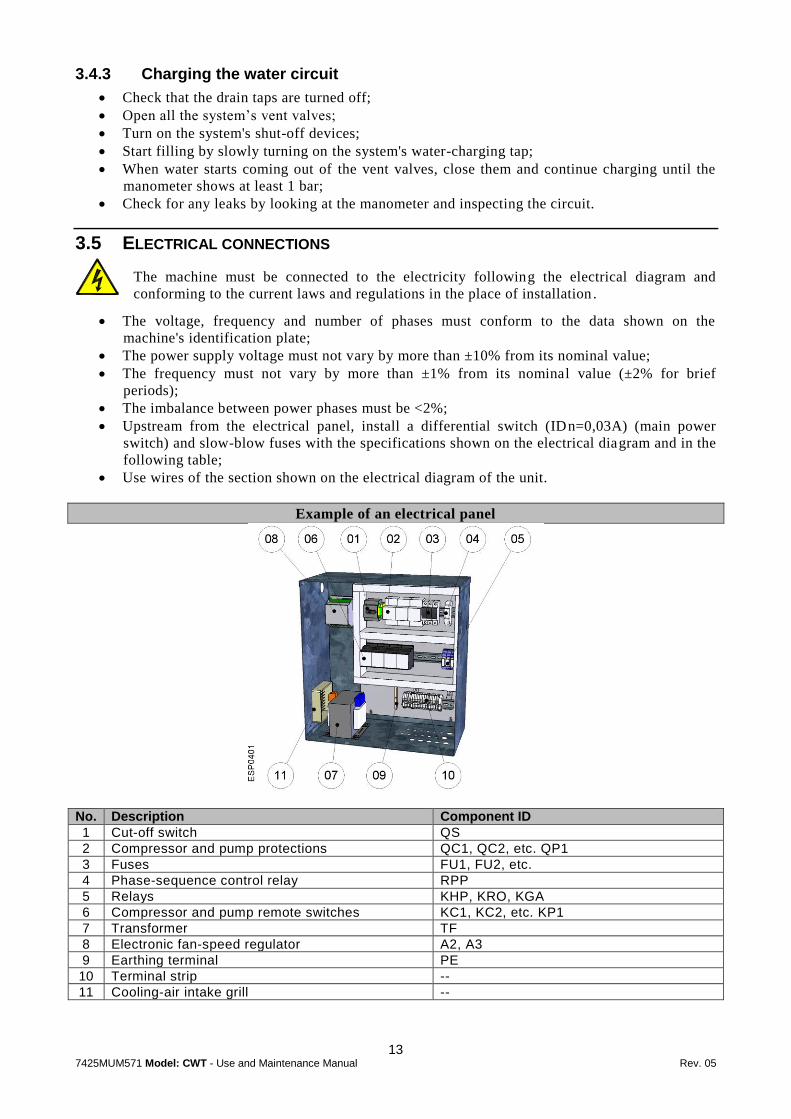
Example of an electrical panel
No. Description Component ID
1 Cut-off switch QS
2 Compressor and pump protections QC1, QC2, etc. QP1
3 Fuses FU1, FU2, etc.
4 Phase-sequence control relay RPP
5 Relays KHP, KRO, KGA
6 Compressor and pump remote switches KC1, KC2, etc. KP1
7 Transformer TF
8 Electronic fan-speed regulator A2, A3
9 Earthing terminal PE
10 Terminal strip --
11 Cooling-air intake grill --

14 7425MUM571 Model: CWT - Use and Maintenance Manual Rev. 05
Attention! Never change the internal electrical connections, as the warranty will be
immediately voided.
Important! Screw the wires solidly to the terminal strip of the cut-off switch and lock the
wire with a cable-gland.
Important! Make the cable entering the machine enters the cable-gland from below: this
prevents rain from dripping inside the machine.
Important! The earth connection is obligatory: connect the earth wire to the terminal
provided in the electrical panel (see the figure of the electrical panel in this paragraph).
The ground wire must be longer than the other wires so that it will be the last one to be pulled if th e
device holding the cable loosens.
3.5.1 Connecting a remote on/off switch and a remote alarm indicator light
A remote on/off switch can be connected to terminal strip in the electrical panel: there are 24V
between the two terminals. To enable a remote switch, move the I/O/REM switch to REM.
An alarm indicator light can be connected to terminal strip (clean contacts) in the electrical panel.
Consult the electrical diagram.
Model Remote on/off Remote alarm indicator
CWT 007÷020 X2.11 – X2.12 X2.13 – X2.14 – X2.15
CWT 025÷030 X2.13 – X2.14 X2.15 – X2.16 – X2.17
CWT 038÷040 X2.13 – X2.14 X2.15 – X2.16 – X2.17
CWT 045÷065 X2.11 – X2.12 X2.13 – X2.14 – X2.15
CWT 075÷090 X2.11 – X2.12 X2.13 – X2.14 – X2.15
CWT 110÷150 X2.11 – X2.12 X2.13 – X2.14 – X2.15
15 7425MUM571 Model: CWT - Use and Maintenance Manual Rev. 05
4
PRELIMINARY CHECKS AND START-UP
4.1 PRELIMINARY CHECKS AND PREPARATION FOR THE FIRST START-UP
Before starting up the unit, it is a good idea to do the following:
Check that the water shut-off valves are open;
Check that the pressure shown on the manometer with the pumps stopped is at least 1 bar (for
closed water systems);
Check that the surrounding temperature is in the range for the machine to function (see
Chapter 7 Operating Limits);
Check that the cut-off on the electrical panel of the machine is open (O position);
Check that the run/stop switch (I/O/REM) in the electrical panel is in the O position;
Check that the mains voltage matches the voltage on the machine's identification plate with a
tolerance of ±10%;
Close the main power supply switch;
Close the cut-off switch on the machine's electrical panel (I position) .
This puts the machine under voltage without starting it up.
Attention! Apply voltage to the machine at least two hours before start -up to give the heating
elements in the compressor housing time to heat the oil inside.
The heating elements limit the quantity of refrigerant dissolved in the oil and prevent the oil from
migrating when the compressors start.
Before start-up, check that the temperature of the lower part of the compressors is at least 10÷15°C
//18÷28°F higher than the surrounding temperature.
4.2 START-UP
To proceed to start-up:
1. Move the remote on/off switch (I/O/REM) on the door of the electrical to position 1;
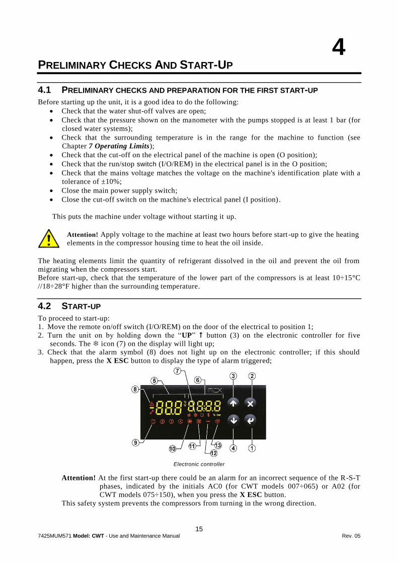
2. Turn the unit on by holding down the “UP” button (3) on the electronic controller for five
seconds. The icon (7) on the display will light up;
3. Check that the alarm symbol (8) does not light up on the electronic controller; if this should
happen, press the X ESC button to display the type of alarm triggered;
Electronic controller
Attention! At the first start-up there could be an alarm for an incorrect sequence of the R-S-T
phases, indicated by the initials AC0 (for CWT models 007÷065) or A02 (for
CWT models 075÷150), when you press the X ESC button.
This safety system prevents the compressors from turning in the wrong direction.
16 7425MUM571 Model: CWT - Use and Maintenance Manual Rev. 05
In this case, turn on the main power supply switch upstream from the machine and
reverse the two phases immediately downstream from the main switch.
Attention! Never reverse the wires downstream from the cut-off switch on the
electrical panel because doing so risks changing the correct sequence of
other devices, such as, for example, the pump and fans.
Repeat the steps from point 1.
4. Check that the pump has started (the pump icon (10) lights up) and check the water pressures
upstream and downstream from the machine on the manometers previously installed;
5. Wait for the electronic controller to verify that the water flow is constant through the signal from
the differential pressure-switch; if the differential pressure-switch intervenes (alarm code A03
when you press the X ESC button), vent the system, check that the shut-off taps and the
functioning of the pump are turned on; reset the alarm by holding down the X ESC button for 5
seconds;
6. Wait for the compressors to start.
4.2.1 Start-up under critical conditions
If the temperatures of the water and air are particularly high and outside operating limits, it is possible
that the chiller is being asked to work in conditions that are too harsh: in this case, the CWT models
with at least two compressors (CWT 025÷150) will partially start, i.e., they will work with only one
compressor until the water slowly returns within operating limits; only then will the machine function
at full load.
For CWT models with one compressor (CWT 007÷020), the consequence of starting up under critical
conditions could be the intervention of the high-pressure pressure switch (to rearm the high-pressure
pressure switch, see paragraph 6.2 Rearming the high-pressure pressure switch).
To overcome this problem, you will have to reduce the thermal load on the machine by shutting off
some of the uses or, if this is not possible, by reducing the flow of water into the evaporator: partially
close the output tap from the chiller and restart the machine.
Operate the chiller under these conditions until the water temperature gradually returns within
operating limits; then, you can turn on the tap completely.
4.3 TURNING OFF THE UNIT
To turn off the chiller, hold down the UP (3) button on the electronic controller for at least 5
seconds or, move the run/stop I/O/REM switch to the O position (see paragraph 5.2 Turning on and
off).
Attention! It is important not to turn the unit off using the main power supply switch or the
cut-off on the machine's electrical panel because this would not provide for the
delayed power-off of the pump regarding the power-off of the compressors, with
the risk of damaging the evaporator; in addition, it would prevent the functioning
of the heating elements in the compressor housing.

17 7425MUM571 Model: CWT - Use and Maintenance Manual Rev. 05
5
ELECTRONIC CONTROLLER
Electronic controller
The electronic controller has two 7-segment displays and a series of icons.
It manages:
The functioning of the compressors to ensure that the water produced has a constant
temperature;
The functioning of the pump;
The speed of the fans;
The prevention of the high-pressure alarm (CWT 025÷150).
Displays:
The state of the unit ( icon) (7);
The state of the compressors (4 compressor icons) (9);
The state of the fans (fan icon) (11);
The state of the pump (pump icon) (10);
The temperature set point (display B) (5);
The temperature of the water produced (display A) (6);
All digital and analogue inputs and outputs (parameters navigation, through displays A and B).
Displays the following alarms:
Water differential pressure switch;
High-pressure pressure switch;
Low-pressure pressure switch;
Anti-freeze thermostat;
Compressor protection - wrong R-S-T phase sequence;
Pump and fan protection - water level in tank insufficient;
Pressure and temperature probe failure.

18 7425MUM571 Model: CWT - Use and Maintenance Manual Rev. 05
5.1 MAIN FUNCTIONS OF THE ELECTRONIC CONTROLLER BUTTONS AND MEANINGS
OF THE ICONS
Button/Icon Functions
ENTER
Accesses the menu.
Goes to the next menu level.
Goes to the mode for editing the selected parameter.
Confirms value entered for a parameter.
ESC
Accesses the list of active alarms.
When navigating the menus, returns to the previous menu level (pressed once).
When navigating the menus, returns to the main page (pressed several times).
Exits from parameter edit mode without saving the changes made.
UP
When pressed for at least 5 seconds, turns the unit on and off.
During menu navigation, scrolls up through the menu items.
Increases the value of the parameter being modified.
Scrolls up through the alarm list.
DOWN
During menu navigation, scrolls down through the menu items.
Decreases the value of the parameter being modified.
Scrolls down through the alarm list.
During the machine’s operation, shows the temperature of the water exiting the evaporator.
During navigation of the menu, indicates the directory above the one where you are.
During the machine’s operation shows the temperature set point for the water.
During navigation of the menu, indicates the directory where you are.
When modifying a parameter, the value to be modified is displayed flashing.
Indicates that the machine is ON, even when the compressors are stopped.
Indicates the presence of one or more active alarms.
They indicate the state of the compressors and, more precisely:
Off: compressor OFF
On: compressor ON
Slow flashing: compressor about to turn on.
Fast flashing: compressor about to turn off.
Indicates the state of the pump, more precisely:
Off: pump OFF
On: pump ON
Fast flashing: pump about to turn off.
Indicates the state of the fans:
On: fans ON
Off: fans OFF.
5.2 TURNING ON AND OFF
To turn the unit on, hold down the UP button (3) for more than five seconds
To turn the unit off, hold down the UP button (3) for more than five seconds
Optionally, once the machine has been turned on using the electronic controller, it can be turned on
and off from the run/stop switch (I/O/REM) on the door of the electrical panel.
Attention! The run/stop I/O/REM switch has precedence over the UP button (3): after
turning the machine office from the run/stop I/O/REM switch, it will not be
possible to restart it with the UP button (3) on the electronic controller.

19 7425MUM571 Model: CWT - Use and Maintenance Manual Rev. 05
5.3 WATER TEMPERATURE: DEAD-ZONE REGULATION
This system is set on three temperature ranges: lower differential - neutral zone - upper differential
and a temperature.
All these values are distributed on the temperature scale as shown in the figure:
The compressors are forced off.
The compressors are progressively turned off as the temperature of the water decreases.
The compressors that are on are kept on and those that are off are kept off.
The compressors are progressively turned on as the temperature of the water increases.
All the compressors are on.
Numerical example:
4°C [39,2°F] 4,5°C
[40,1°F] From 6°C[42,8°F]
to 7°C[44,6°F]
Set point = 7°C [44,6°F]
From 7°C[44,6°F] to 8°C[46,4°F]
From 8°C[46,4°F] to 9°C[48,2°F]
Above 9°C[48,2°F]
4°C [39,2°F] 4,5°C
[40,1°F] From 9°C[48,2°F]
to 10°C[50°F]
Set point = 10°C [50°F]
From 10°C[50°F] to 11°C[51,8°F]
From 11°C[51,8°F] to 12°C[53,6°F]
Above 12°C[53,6°F]
The set point of the water can be changed: the other parameters (differentials and neutral zone) remain
constant and follow the set-point value, moving on the temperature scale (see the numeric examples in
the table above).
5.4 CHANGING THE SET POINT
If, during the offer phase, you did not specify that the chiller must produce water at
temperatures close to 0°C//32°F, or below, you must contact our company. See paragraph 7.2
Low water temperatures.
To change the set point of the exiting water, proceed as follows:
from the main screen, press ENTER ;
use the DOWN button to go to the PAR menu;
Press ENTER and use the DOWN button to go to the REG menu. Press ENTER ;
In the REG SET menu, press ENTER and the set point will be displayed. To change it, press
ENTER and the value will flash. Use the UP and DOWN buttons to set the desired
value. To confirm it, press ENTER ;
To exit without saving it, press X ESC;
Press X ESC again until you return to the main screen.

20 7425MUM571 Model: CWT - Use and Maintenance Manual Rev. 05
5.5 CHANGING THE TYPE OF RESTART AFTER A POWER FAILURE
In the case of a power failure, the chiller can behave in three different ways when power is restored:
Stay off;
Start;
Return to the same condition it was in when the power failed.
To select one of these options, proceed as follows:
From the main screen, press ENTER ;
Use the DOWN to go to the PAR menu. Press ENTER ;
Go to the PAR GEN menu. Press ENTER ;
In the GEN STU menu, press ENTER . In the Y02 menu, the type of restart currently set will
be displayed, which can be one of the following:
EQUA: when the power returns, the machine will work in the same way as before the
power failed;
ON: when the power returns, the machine will start;
OFF: when the power returns, the machine will stay off;
To change the type of restart, press ENTER and the parameter begins to flash. Use the UP
and DOWN buttons to select the desired parameter and confirms with ENTER ;
To return to the main screen, press X ESC four times.
5.6 CHANGING THE SERIAL ADDRESS (MODBUS AND CAN)
If you are installing a serial network with several devices, it may be necessary to change the serial
address of the electronic controller, which is set to 1 at the factory.
From main screen, press ENTER ;
Using the DOWN button, go the PAR menu. Press ENTER . In the PAR GEN menu, press
ENTER ;
Use the DOWN arrow to scroll to the GEN SER menu and press ENTER : the current serial
address is displayed;
From the SER menu, press ENTER : the current value will flash. Use the UP and DOWN
arrows to set the desired value;
To return to the main screen, press X ESC four times.
5.7 DISPLAY OF INPUTS AND OUTPUTS
It is possible to display the analogue and digital outputs to check the operation of the machine and its
main components.
From the main screen, press ENTER ;
Use the DOWN button to move to the I/O menu;
From here, press ENTER to access the I/O IOd menu;
Press ENTER and, using the UP and DOWN buttons, you can display all the values of
the analogue and digital inputs and outputs;
Press X ESC again until you return to the main screen.
The following values can be displayed:

21 7425MUM571 Model: CWT - Use and Maintenance Manual Rev. 05
I/O Numbering Function
Analog Input 1 Evaporator Water Inlet Temperature
2 Evaporator Water Outlet Temperature
3 Discharge Refrigerant Pressure Circuit 1
4 Suction Refrigerant Pressure Circuit 1
5 -------------
6 -------------
7 Discharge Refrigerant Pressure Circuit 2
8 Suction Refrigerant Pressure Circuit 2
Digital Input 1 On/Off
2 High Pressure Switch Circuit 1
3 -------------
4 Water differential Pressure Switch
5 Compressor Overload Circuit 1
6 Pump 1/Fan Overload
7 High Pressure Switch Circuit 2
8 -------------
9 Compressor Overload Circuit 2
10 Reverse Phase Protection
11 -------------
12 -------------
13 -------------
14 -------------
Analog Output 1 Fans Speed Circuit 1
2 -------------
3 -------------
4 -------------
5 -------------
Digital Output 1 General Alarm
2 Compressor 1
3 Compressor 2
4 Compressor 3
5 Pump 1
6 -------------**
7 Compressor 4
8 Compressor 5
9 Compressor 6
10 -------------
11 -------------
12 -------------
** Compressor 4 for CWT with four compressors.

22 7425MUM571 Model: CWT - Use and Maintenance Manual Rev. 05
5.8 DISPLAYING THE SOFTWARE RELEASE VERSION OF THE ELECTRONIC
CONTROLLER
From the main screen, press ENTER ;
Use the DOWN button to go to the SER menu. Press ENTER ;
From the SER INF menu, press ENTER and here you can display the version of the software
release installed in your controller;
Press X ESC again until you return to the main screen.
5.9 DISPLAYING THE COMPRESSOR AND PUMP COUNTERS
From the main screen, press ENTER ;
Use the DOWN button to go to the HRS menu. Press ENTER ;
In the HRS COH menu, press ENTER ;
Use the arrows to display the working hours of the compressors (C01 C02, etc.);
To display the working hours of the pump, after going to the HRS COH menu, use the DOWN
button to scroll down to the HRS EPH menu and press ENTER ;
From here you can display the working hours of the pump (EP1);
To exit, Press X ESC again until you return to the main screen.
5.10 ALARMS
An alarm condition is signalled by the Alarm icon (8).
Some alarms must be rearmed manually while for others, the reset is automatic or semi-automatic.
Manual reset: these alarms must be reset, which can only be done when the alarm condition no
longer exists; only then can the machine resume operation;
Automatic reset: the alarm is automatically deactivated as soon as the alarm condition ceases
and the machine restarts by itself. However, the signal (Alarm icon (8)) remains on the display
until the alarm code is displayed;
Semi-automatic reset: semi-automatic alarms behave like automatic alarms; but if the same
semi-automatic alarm occurs 5 times in 90 minutes, that alarm becomes a manual alarm;
therefore to restart the machine, you will have to remove the cause of the alarm and reset it.
5.10.1 Displaying and resetting alarms
The Alarm icon (8) turns on to indicate an alarm.
To display the code of the alarm that intervened, press the X ESC button; use the UP and DOWN
buttons to display the codes of any other alarms that intervened at the same time.
To reset an alarm, the condition that caused it must no longer exist: for example, if the low -
pressure pressure switch has intervened, the alarm can only be reset when the pressure has
risen beyond the reset value (see paragraph 6.1 Calibrating security devices and type of
rearm).
Then, after displaying the alarm, wait for normal conditions to be restored, press X ESC
again, hold it down for 5 seconds and the alarm will be reset.
5.10.2 Displaying of alarm history
From the main screen, press ENTER ;
Use the DOWN button to go to the ALA menu. Press ENTER ;
Use the DOWN button to go to the ALA AHS menu. Press ENTER ;
Press ENTER and the alarm history is displayed.

23 7425MUM571 Model: CWT - Use and Maintenance Manual Rev. 05
5.10.3 Table of alarm codes
Alarm code for CWT Alarm description Type of rearm
007÷065 075÷150
A01 A01 General alarm Automatic
A02 Phase sequence alarm Automatic
A03 A03 Evaporator flow switch alarm Manual
AP1 AP1 Pump 1 overload alarm and/or fans overload and/or level switch alarm Manual
AP2 AP2 Pump 2 overload alarm Manual
AP9 AP9 Backup pump running Automatic
A07 A07 Low air temperature alarm Automatic
A09 A09 High temperature warning Automatic
AE1 AE1 Evaporator ice alarm Semiautomatic
AH1 AH1 Circuit 1 high pressure alarm Manual
AH2 Circuit 2 high pressure alarm Manual
AL1 AL1 Circuit 1 low pressure alarm Semiautomatic
AL2 Circuit 2 low pressure alarm Semiautomatic
AM1 AM1 Circuit 1 high suction pressure alarm Semiautomatic
AM2 Circuit 2 high suction pressure alarm Semiautomatic
AV1 AV1 Circuit 1 vacuum alarm Manual
AV2 Circuit 2 vacuum alarm Manual
AC1 Circuit 1 compressors overload and/or phase sequence alarm Manual
AC1 Circuit 1 compressors overload Manual
AC2 Circuit 2 compressors overload Manual
A7A A7A Alarm probe inlet temperature evaporator Automatic
A7B A7B Alarm probe outlet temperature evaporator Automatic
A7G A7G Alarm probe discharge pressure circuit 1 Automatic
A7H Alarm probe discharge pressure circuit 2 Automatic
A7K A7K Alarm probe outlet temperature Automatic
A7L A7L Alarm probe remote set Automatic
A7M A7M Alarm probe outlet temperature condenser 1 Automatic
A7N Alarm probe outlet temperature condenser 2 Automatic
A7V A7V Alarm probe suction pressure circuit 1 Automatic
A7W Alarm probe suction pressure circuit 2 Automatic
A8A A8A Alarm probe discharge temperature circuit 1 Automatic
A8B Alarm probe discharge temperature circuit 2 Automatic
A8W A8W Alarm probe suction temperature circuit 1 Automatic
A8X Alarm probe suction temperature circuit 2 Automatic
dT1 dT1 Circuit 1 high discharge temperature Automatic
dT2 Circuit 2 high discharge temperature Automatic
Cn Cn Expansion communication fault Automatic
24 7425MUM571 Model: CWT - Use and Maintenance Manual Rev. 05
6
SAFETY DEVICES
CWT chillers have a series of safety devices that limit the machine's temperature and pressure values
to ensure that it operates within the anticipated limits and to avoid dangerous situations.
When they reach their calibration value, most of the security devices trigger an alarm managed by the
electronic controller.
Here is a list of dangerous situations, including the relative safety device and its location.
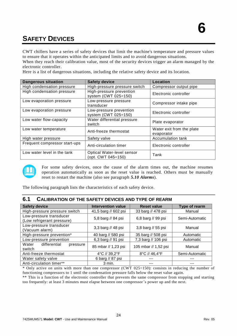
Dangerous situation Safety device Location
High condensation pressure High-pressure pressure switch Compressor output pipe
High condensation pressure High-pressure prevention system (CWT 025÷150)
Electronic controller
Low evaporation pressure Low-pressure pressure transducer
Compressor intake pipe
Low evaporation pressure Low-pressure prevention system (CWT 025÷150)
Electronic controller
Low water flow-capacity Water differential pressure switch
Plate evaporator
Low water temperature Anti-freeze thermostat
Water exit from the plate evaporator
High water pressure Safety valve Accumulation tank
Frequent compressor start-ups Anti-circulation timer Electronic controller
Low water level in the tank Optical Water-level sensor (opt. CWT 045÷150)
Tank
For some safety devices, once the cause of the alarm times out, the machine resumes
operation automatically as soon as the reset value is reached. Others must be manually
reset to restart the machine (also see paragraph 5.10 Alarms).
The following paragraph lists the characteristics of each safety device.
6.1 CALIBRATION OF THE SAFETY DEVICES AND TYPE OF REARM
Safety device Intervention value Reset value Type of rearm
High-pressure pressure switch 41,5 barg // 602 psi 33 barg // 478 psi Manual
Low-pressure transducer (Low refrigerant pressure)
5,8 barg // 84 psi 6,8 barg // 99 psi Semi-Automatic
Low-pressure transducer (Vacuum alarm)
3,3 barg // 48 psi 3,8 barg // 55 psi Manual
High-pressure prevention* 40 barg // 580 psi 35 barg // 508 psi Automatic
Low-pressure prevention 6,3 barg // 91 psi 7,3 barg // 106 psi Automatic
Water differential pressure switch
85 mbar // 1,23 psi 105 mbar // 1,52 psi Manual
Anti-freeze thermostat 4°C // 39,2°F 8°C // 46,4°F Semi-Automatic
Water safety valve 6 barg // 87 psi --- ---
Anti-circulation timer** 3 min. --- ---
* Only active on units with more than one compressor (CWT 025÷150): consists in reducing the number of
functioning compressors to 1 until the condensation pressure falls below the reset value again.
** This is a function of the electronic controller that prevents the same compressor from stopping and starting
too frequently: at least 3 minutes must elapse between one compressor ’s power up and the next.
25 7425MUM571 Model: CWT - Use and Maintenance Manual Rev. 05
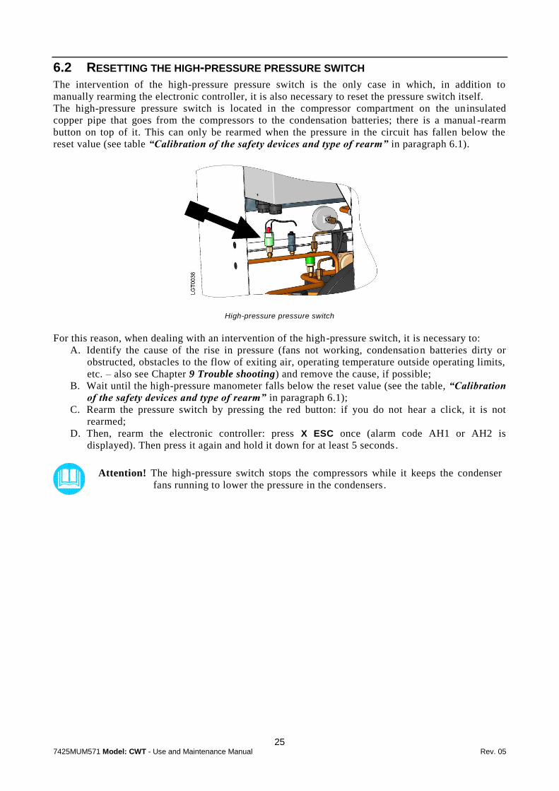
6.2 RESETTING THE HIGH-PRESSURE PRESSURE SWITCH
The intervention of the high-pressure pressure switch is the only case in which, in addition to
manually rearming the electronic controller, it is also necessary to reset the pressure switch itself.
The high-pressure pressure switch is located in the compressor compartment on the uninsulated
copper pipe that goes from the compressors to the condensation batteries; there is a manual -rearm
button on top of it. This can only be rearmed when the pressure in the circuit has fallen below the
reset value (see table “Calibration of the safety devices and type of rearm” in paragraph 6.1).
High-pressure pressure switch
For this reason, when dealing with an intervention of the high-pressure switch, it is necessary to:
A. Identify the cause of the rise in pressure (fans not working, condensation batteries dirty or
obstructed, obstacles to the flow of exiting air, operating temperature outside operating limits,
etc. – also see Chapter 9 Trouble shooting) and remove the cause, if possible;
B. Wait until the high-pressure manometer falls below the reset value (see the table, “Calibration
of the safety devices and type of rearm” in paragraph 6.1);
C. Rearm the pressure switch by pressing the red button: if you do not hear a click, it is not
rearmed;
D. Then, rearm the electronic controller: press X ESC once (alarm code AH1 or AH2 is
displayed). Then press it again and hold it down for at least 5 seconds .
Attention! The high-pressure switch stops the compressors while it keeps the condenser
fans running to lower the pressure in the condensers.
26 7425MUM571 Model: CWT - Use and Maintenance Manual Rev. 05
7
OPERATING LIMITS
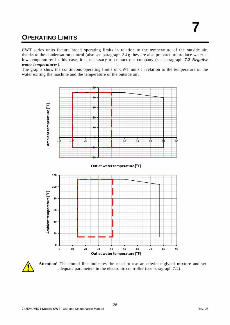
CWT series units feature broad operating limits in relation to the temperature of the outside air,
thanks to the condensation control (also see paragraph 2.4); they are also prepared to produce water at
low temperature: in this case, it is necessary to contact our company (see paragraph 7.2 Negative
water temperatures).
The graphs show the continuous operating limits of CWT units in relation to the temperature of the
water exiting the machine and the temperature of the outside air.
Attention! The dotted line indicates the need to use an ethylene glycol mixture and set
adequate parameters in the electronic controller (see paragraph 7.2).

27 7425MUM571 Model: CWT - Use and Maintenance Manual Rev. 05
7.1 MINIMUM WATER FLOW
It is recommended to grant a minimum water flow to the chiller in order to avoid serious
damages to the evaporator and to the whole machine (see following table).
Modél CWT 007 010 015 018 020 025 030 038 040 045 055 065 075 090 110 130
Minimum water flow
[m3/h]
0.45 0.65 0.85 1.00 1.30 1.30 1.65 2.00 2.55 2.55 2.90 3.60 4.40 4.90 6.20 7.60
Check that water temperature difference between inlet and outlet of the chiller is less than
14.4°F/8°C; higher values could be the symptom of an insufficient water flow.
7.2 LOW WATER TEMPERATURES (<32°F//0°C)
If it was not anticipated that the chiller unit offered was to produce water at temperatures
close to 0°C//32°F, or below, you should contact our company.
To achieve temperatures that are negative, or near zero, it is necessary to use anti-freeze
(ethylene glycol) in percentages that depend on the desired temperature; it is also necessary
to change the calibration of the anti-freeze thermostat and the relative parameters.
CWT units can operate with water and ethylene glycol mixtures up to a concentration of
40%.
NOTE The anti-freeze thermostat setting can only be changed at a higher level of programming of
the electronic control: please request the password by contacting our company.
7.2.1 Changing the setting of the anti-freeze thermostat and relative parameter
Please ask our company for the password for changing the parameters.
For operating with low water temperature, it is recommended to set the following parameters:
Parameter Description Unit Set
Desired water temperature °C [°F]
-10 [14]
-7 [19,4]
-5 [23]
-3 [26,6]
0 [32]
2 [35,6]
5 [41]
7 [44,6]
SCL Setpoint minimum limit °C [°F]
-11 [12,2]
-8 [17,6]
-6 [21,2]
-4 [24,8]
-1 [30,2]
1 [33,8]
4 [39,2]
6 [42,8]
SC1 Cooling temperature setpoint °C [°F]
-10 [14]
-7 [19,4]
-5 [23]
-3 [26,6]
0 [32]
2 [35,6]
5 [41]
7 [44,6]
dd3 Min Temp. for OFF compressor °C [°F]
-13 [8,6]
-10 [14]
-8 [17,6]
-6 [21,2]
-3 [26,6]
-1 [30,2]
2 [35,6]
4.5 [40,1]
AIS Ice alarm setpoint °C [°F]
-14 [6,8]
-11 [12,2]
-9 [15,8]
-7 [19,4]
-4 [24,8]
-2 [28,4]
0 [32]
4 [39,2]
ALt Low pressure alarm setpoint [barg] 3,0 3,5 3,8 4,2 4,6 5,0 5,6 5,8
Percentage of ethylene glycol % 40 30 30 30 25 20 15 0
Follow this path:
From the main screen press ENTER ;
Press ENTER at LOG-Login;
Enter the password1 using UP /DOWN key and ENTER to confirm the value;
Use the DOWN key until the PAR menu is reached, press ENTER ;
Use the DOWN key until the PAR reG menu is reached, press ENTER ;
Use the DOWN key until the reG SEt menu is reached, press ENTER ;
1 Please contact our company.
28 7425MUM571 Model: CWT - Use and Maintenance Manual Rev. 05
Use the DOWN key to reach SCL-Setpoint minimum limit and SC1-Cooling temperature
setpoint for set the two parameters. For set the value press ENTER to select the parameter,
UP /DOWN key to change the value and ENTER to confirm the new value;
Press ESC X to return to previous menu level;
Use the DOWN key until the rEG ddZ menu is reached, press ENTER ;
Use the DOWN key to reach dd3- Min Temp. for OFF compressor and press ENTER for
set the value, UP /DOWN key to change the value and ENTER to confirm the new
value;
Press ESC X two times to return to previous menu level;
Use the DOWN key until the PAR ALA menu is reached, press ENTER ;
Use the DOWN key until the ALA ICE menu is reached, press ENTER ;
At AIS-Ice alarm setpoint press ENTER for set the value, UP /DOWN key to change
the value and ENTER to confirm the new value;
Press ESC X one times to return to previous menu level;
Use the DOWN key until the ALA LP menu is reached, press ENTER ;
Use the DOWN key until the ALt-Low pressure alarm setpoint is reached, press ENTER
for set the value, UP /DOWN key to change the value and ENTER to confirm the new
value;
Press ESC X several times to return to main menu.

29 7425MUM571 Model: CWT - Use and Maintenance Manual Rev. 05
8
MAINTENANCE AND INSPECTIONS AND PERIODIC CHECKS
To keep the machine running properly and providing the guaranteed performance required,
it is necessary to make some periodic checks.
Operation Frequency Execution
Check that the temperature of the water produced is in the required interval.
Daily
User
Check for the presence of any alarm signals. Daily
Check the functioning of the fans. Monthly
Check the pressure of the water circuit with the pump stopped (verify that it is about 1 bar // 15 psi)
Monthly
Check that the temperature of the air is compatible with the operating limits of the machine.
Monthly
Clean the air filters. Monthly(1)
Clean the condensation batteries with a jet of compressed air. Yearly (1)
Clean the water filter. Monthly(2)
Specialised personnel
Check that the refrigerant liquid peep hole is clear or, at most, with a few bubbles (check with the compressor running).
Every 6 months
Check that the undercooling and superheating values are, respectively between 3÷5K // 5,4÷9°F and 5÷7K // 9÷12,6°F.
Every 6 months
Check for traces of oil on the pipes of the chilling circuit (symptom of refrigerant leaks)
Every 6 months
Check the tightness of the electrical terminals both inside the electrical panel and on the terminal strips of the compressors.
Yearly
Check the contacts of the remote switches; if they show signs of deterioration, replace them.
Yearly
Check that the current absorbed by the machine is within the values on the identification plate.
Every 6 months
If the unit will not be used for a long time, drain the water from the pipes and the machine to avoid the formation of ice during the winter (3).
Extraordinary User
(1) It may be necessary to carry this out more frequently in the case of particularly dirty environments.
(2) We recommend an extraordinary cleaning of the filter after the machine has been operating for the first week.
(3) It is not necessary to do this if the system has been charged with an anti-freeze solution (water and a suitable percentage of
glycol) (see paragraph 3.4.2 Use of ethylene glycol as a winter anti-freeze).
Attention! Before carrying out any maintenance on the unit or accessing internal parts, make
sure you have cut-off the electricity.
Attention! The upper part of the compressor housing and the output pipe are hot. Be
especially careful when working near them.

30 7425MUM571 Model: CWT - Use and Maintenance Manual Rev. 05
9
TROUBLESHOOTING
Cause Alarm signal or symptom
Solution Execution
1. The unit does not start
Contacts of the main differential switch open.
Electronic controller off Close the contacts
User
Unit's electrical panel cut-off switch open.
Electronic controller off Close the contacts
User
I/O/REM switch in the O or REM position
Electronic controller on Move the switch to I User
No consent from the water differential switch
A03 Check the functioning of the pump, vent the plumbings
User
Compressor timer active
The compressor icon on the display of the electronic controller is flashing
Wait 3 minutes User
No consent from the service thermostat
Plant water at temperature (see display A)
Apply a thermal load to the machine or lower the set point
User
No consent from the anti-freeze thermostat
AE1
Reset a temperature of the water (set point) compatible with the calibration of the anti-freeze thermostat (see table in paragraph 7.2.1)
User
Service and anti-freeze probe defective
A7K Check contacts and replace, if necessary
Specialised personnel
Entering water temperature probe defective
A7B Check contacts and replace, if necessary
Specialised personnel
Intervention of the main differential switch
Electronic controller off Look for current dispersion inside the machine
Specialised personnel
2. The compressor doesn't start
Intervention of the thermal protection inside the compressor
The contactor of the compressor is on but the compressor is stopped
Wait for cooling: check that the compressor is working under normal conditions. Check for insufficient refrigerant in the circuit (see point 8).
Specialised personnel
Contactor of the compressor open The compressor icon is on but the compressor is stopped
Check the voltage at the coil of the contactor of the compressor and the continuity of the coil itself
Specialised personnel

31 7425MUM571 Model: CWT - Use and Maintenance Manual Rev. 05
Cause Alarm signal or
symptom Solution Execution
2. (continue) The compressor doesn’t start
Magnetothermic protection of the compressors open (QC1, QC2, Etc.)
AC1 (for CWT 007÷150 circuit 1)
AC2 (for CWT 075÷150 circuit 2)
Look for short circuits in the motor windings of the compressor. Check for possible over-absorption of current due to too low voltage; combined with operating conditions near the limits: check the power supply voltage and operating conditions
Specialised personnel
Intervention of the phase-sequence relay
AC1 (for CWT 007÷150)
A02 (for CWT 075÷150)
Reverse the two phases upstream from the cut-off switch of the unit's electrical panel (see paragraph 4.2)
Specialised personnel
3. Intervention of the high-pressure pressure switch
Condenser obstructed or insufficient air flow-capacity
AH1 (for CWT 007÷150 circuit 1)
AH2 (for CWT 075÷150 circuit 2)
Remove dirt from the condenser and any obstacles to the flow of air. Wait for the refrigerant pressure to drop below the reset value (33 bar g), then rearm the high-pressure switch by pressing the button on top of it (see figure in paragraph 6.2)
User
The unit has operated outside its operating limits (such as air or water too hot)
AH1 (for CWT 007÷150 circuit 1)
AH2 (for CWT 075÷150 circuit 2)
If possible, restore conditions that are compatible with the operating limits. Rearm the pressure switch (paragraph 6.2).
User
Fan not working See point 6
Excessive refrigerant charge High subcooling (greater than 18°F//10 K)
Drain excess refrigerant
Specialised personnel
Presence of incondensable gas or air in the refrigerant circuit
Presence of bubbles on the refrigerant sight glass, also with subcooling values greater than 9°F//5 K
Drain the refrigerant circuit, create vacuum and recharge
Specialised personnel
Refrigerant filter clogged or thermostatic valve stuck
Pipe downstream from the component covered with frost.
Check and replace.
Specialised personnel
4. Intervention of the water differential pressure switch Taps of the machine are turned closed A03 Open the taps User
Water circulation pump blocked or defective
A03 Unlock or replace the pump
Specialised personnel
Water pump stopped A03
Pump icon lit.
Check the voltage at the coil of the contactors of the pump and the continuity of the coil itself
Specialised personnel

32 7425MUM571 Model: CWT - Use and Maintenance Manual Rev. 05
Cause Alarm signal or symptom
Solution Execution
5. Intervention of the low pressure transducer
Refrigerant filter clogged or thermostatic valve stuck
Pipe downstream from the component covered with frost.
Check and replace
Specialised personnel
Insufficient refrigerant charge See point 8
6. Fans don't start Very low outside air temperatures and consequent intervention of the condensation control
Fan icon off. Condensation pressure normal
The machine is working anyway
No voltage output from the fan-speed regulator
Fan icon on and fans stopped
Check the voltage output from the regulator and replace, if necessary
Specialised personnel
Intervention of the thermal protection inside the fan
AP1
Check that the working conditions of the machine (outside air temperature) are compatible with the operating limits. Wait for the fan motor to cool.
User
Fan fuse blown. Fan icon on and fans stopped
Look for short circuits in the motor windings of the fans. Check the fan roller bearings.
Specialised personnel
Electrical connections of the fans loose
Fan icon on and fans stopped
Check and tighten Specialised personnel
7. The unit is working without ever stopping
Excessive thermal load
Reduce the thermal load. Reduce the temperature of the incoming water and/or the flow-capacity of the water by closing the exit tap of the unit a little.
User
No refrigerant See point 8
8. Compressor suction pipe covered with frost
No refrigerant
High superheating, low subcooling and high discharge temperature of the compressor. Traces of oil on the refrigerant circuit.
Check the refrigerant circuit with a leak detector. Repair any ruptures and recharge the circuit.
Specialised personnel
9. The pump doesn't start magnetothermic protection of the pump open
Excessive water flow-capacity; the pump is absorbing too much current
AP1 AP2
Reduce the flow-capacity of the water by closing the output tap of the pump a little bit. Rearm the thermomagnetic protection of pump QP1.
User
Short circuit or overcurrent AP1 AP2
Look for a short circuit in the winding of the pump motor. Check for possible over-absorption of current due to too low voltage; check the power supply voltage.
Specialised personnel

33 7425MUM571 Model: CWT - Use and Maintenance Manual Rev. 05
10
DISMANTLING THE CHILLER
If the chiller is being dismantled, you must separate it into parts of homogeneous material.
The following table lists the main materials of the various components of the machine.
Part Material
Refrigerant fluid R410A, Oil
Panelling and supports Carbon steel, epoxy paint
Chiller compressor Steel, Copper, Aluminium, Oil
Plate exchanger (evaporator) Steel, Copper
Condenser Aluminium, Carbon Steel
Pipes Copper
Fan Aluminium, Copper, Steel
Valves Steel, Bronze
Insulation Synthetic rubber without CFC, EPS, Polyurethane
Electrical wires Copper, PVC
Electrical parts PVC, Copper, Bronze
We recommend that you follow current safety norms for the disposal of each single material.
The refrigerant contains particles of lubrication oil from the chiller compressor.
Dispose of refrigerant properly. Remove it from the chiller with suitable tools and
deliver it to authorised collection centres that will treat it and make it reusable

34 7425MUM571 Model: CWT - Use and Maintenance Manual Rev. 05
11
WATER DIAGRAMS
VERSION WITH SINGLE PUMP – TP P3/P5
VERSION WITH DOUBLE PUMP – TP D3/D5
KEY

35 7425MUM571 Model: CWT - Use and Maintenance Manual Rev. 05
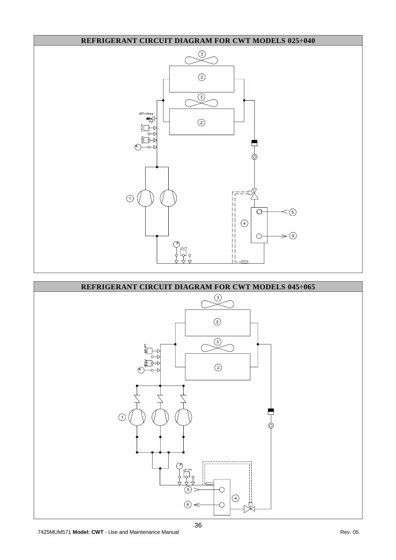
12
REFRIGERANT CIRCUITS DIAGRAMS
KEY
REFRIGERANT CIRCUIT DIAGRAM FOR CWT MODELS 007÷020
36 7425MUM571 Model: CWT - Use and Maintenance Manual Rev. 05
REFRIGERANT CIRCUIT DIAGRAM FOR CWT MODELS 025÷040
REFRIGERANT CIRCUIT DIAGRAM FOR CWT MODELS 045÷065

37 7425MUM571 Model: CWT - Use and Maintenance Manual Rev. 05
REFRIGERANT CIRCUIT DIAGRAM FOR CWT MODELS 075÷150

38 7425MUM571 Model: CWT - Use and Maintenance Manual Rev. 05
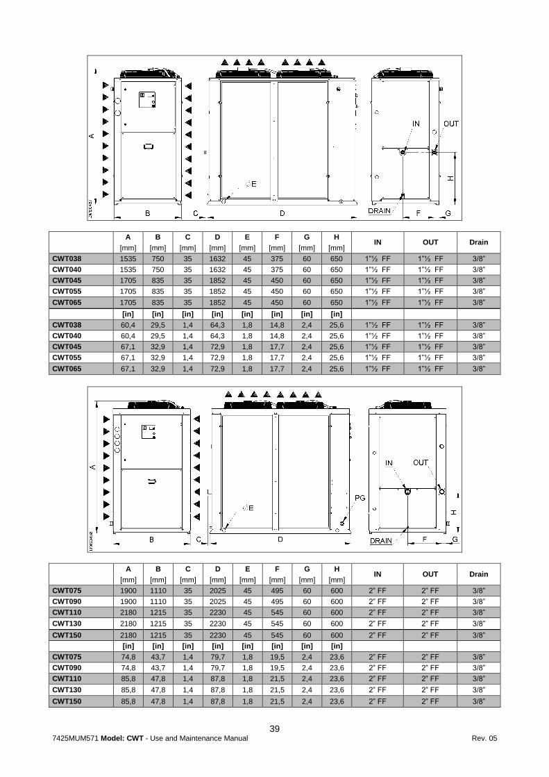
13
DIMENSIONAL DRAWINGS
A B C D E F G H I IN OUT Drain
[mm] [mm] [mm] [mm] [mm] [mm] [mm] [mm] [mm]
CWT007 1335 670 35 995 45 270 50 380 125 1” FF 1” FF 3/8”
CWT010 1335 670 35 995 45 270 50 380 125 1” FF 1” FF 3/8”
CWT015 1335 670 35 995 45 270 50 380 125 1” FF 1” FF 3/8”
[in] [in] [in] [in] [in] [in] [in] [in]
CWT007 52,6 26,4 1,4 39,2 1,8 10,6 2,0 15,0 4,9 1” FF 1” FF 3/8”
CWT010 52,6 26,4 1,4 39,2 1,8 10,6 2,0 15,0 4,9 1” FF 1” FF 3/8”
CWT015 52,6 26,4 1,4 39,2 1,8 10,6 2,0 15,0 4,9 1” FF 1” FF 3/8”
A B C D E F G H IN OUT Drain
[mm] [mm] [mm] [mm] [mm] [mm] [mm] [mm]
CWT018 1425 670 35 1205 45 275 45 505 1” FF 1” FF 3/8”
CWT020 1425 670 35 1205 45 275 45 505 1” FF 1” FF 3/8”
CWT025 1425 670 35 1205 45 275 45 505 1” FF 1” FF 3/8”
CWT030 1425 670 35 1205 45 275 45 505 1” FF 1” FF 3/8”
[in] [in] [in] [in] [in] [in] [in] [in]
CWT018 56,1 26,4 1,4 47,4 1,8 10,8 1,8 19,9 1” FF 1” FF 3/8”
CWT020 56,1 26,4 1,4 47,4 1,8 10,8 1,8 19,9 1” FF 1” FF 3/8”
CWT025 56,1 26,4 1,4 47,4 1,8 10,8 1,8 19,9 1” FF 1” FF 3/8”
CWT030 56,1 26,4 1,4 47,4 1,8 10,8 1,8 19,9 1” FF 1” FF 3/8”
39 7425MUM571 Model: CWT - Use and Maintenance Manual Rev. 05
A B C D E F G H IN OUT Drain
[mm] [mm] [mm] [mm] [mm] [mm] [mm] [mm]
CWT038 1535 750 35 1632 45 375 60 650 1”½ FF 1”½ FF 3/8”
CWT040 1535 750 35 1632 45 375 60 650 1”½ FF 1”½ FF 3/8”
CWT045 1705 835 35 1852 45 450 60 650 1”½ FF 1”½ FF 3/8”
CWT055 1705 835 35 1852 45 450 60 650 1”½ FF 1”½ FF 3/8”
CWT065 1705 835 35 1852 45 450 60 650 1”½ FF 1”½ FF 3/8”
[in] [in] [in] [in] [in] [in] [in] [in]
CWT038 60,4 29,5 1,4 64,3 1,8 14,8 2,4 25,6 1”½ FF 1”½ FF 3/8”
CWT040 60,4 29,5 1,4 64,3 1,8 14,8 2,4 25,6 1”½ FF 1”½ FF 3/8”
CWT045 67,1 32,9 1,4 72,9 1,8 17,7 2,4 25,6 1”½ FF 1”½ FF 3/8”
CWT055 67,1 32,9 1,4 72,9 1,8 17,7 2,4 25,6 1”½ FF 1”½ FF 3/8”
CWT065 67,1 32,9 1,4 72,9 1,8 17,7 2,4 25,6 1”½ FF 1”½ FF 3/8”
A B C D E F G H IN OUT Drain
[mm] [mm] [mm] [mm] [mm] [mm] [mm] [mm]
CWT075 1900 1110 35 2025 45 495 60 600 2” FF 2” FF 3/8”
CWT090 1900 1110 35 2025 45 495 60 600 2” FF 2” FF 3/8”
CWT110 2180 1215 35 2230 45 545 60 600 2” FF 2” FF 3/8”
CWT130 2180 1215 35 2230 45 545 60 600 2” FF 2” FF 3/8”
CWT150 2180 1215 35 2230 45 545 60 600 2” FF 2” FF 3/8”
[in] [in] [in] [in] [in] [in] [in] [in]
CWT075 74,8 43,7 1,4 79,7 1,8 19,5 2,4 23,6 2” FF 2” FF 3/8”
CWT090 74,8 43,7 1,4 79,7 1,8 19,5 2,4 23,6 2” FF 2” FF 3/8”
CWT110 85,8 47,8 1,4 87,8 1,8 21,5 2,4 23,6 2” FF 2” FF 3/8”
CWT130 85,8 47,8 1,4 87,8 1,8 21,5 2,4 23,6 2” FF 2” FF 3/8”
CWT150 85,8 47,8 1,4 87,8 1,8 21,5 2,4 23,6 2” FF 2” FF 3/8”
