use of electrical resistive heating for … · presented by: howard nichols, pe trc ... • nysdec...
TRANSCRIPT

1
USE OF ELECTRICAL RESISTIVE HEATING FOR THE REMEDIATION OF CVOC AND PETROLEUM IMPACTS IN SOIL AND GROUNDWATERNEW YORK CITY, NEW YORK
NEWMOA Conference – June 2012Presented by: Howard Nichols, PE
TRC Environmental Corp.
Introduction
• Site is a former industrial property located in New York City, New York.
• Property is slightly larger than 1 acre .
• Former Site operations included a garage• Former Site operations included a garage.
• TRC was retained in 2008 to
assess remedial alternatives
and advance to site closure.
• Multiple alternatives were
screened to address soil
and ground water impacts.
2
and ground water impacts.
• Electrical Resistive Heating
(ERH) was ultimately selected
and implemented over a 9
month operational period.

2
Site Impacts
• Site was impacted with petroleum products, TCE and daughter products in the soil and groundwater.
– Max TCE soil concentration was >10,000 mg/kg
– Max TCE groundwater concentration >400,000 g/L
• Petroleum impacts had been mostly removed in an earlier remedial excavation; however a 2 foot layer of residual product remained near the water table, which es dua p oduct e a ed ea t e ate tab e, cperiodically manifested greater than 1 foot of free product in on-site monitoring wells.
• Product samples indicated moderately to highly weathered hydraulic and fuel oils.
3
Site Geology
Shallow and intermediate zones separated by organic clay lenses
Clay layer was identified in every boring; however thickness and depth were not consistent.
Complex geology impacted delineation and remedial
4
delineation and remedial technology selection.

3
Treatment Area Description
• The treatment area covered approximately 11,000 square feet (~1/4 acre).
• Targeted treatment depths varied between 25 and 40Targeted treatment depths varied between 25 and 40 feet below grade.
– Shallow treatment was intended to address area impacted only with petroleum hydrocarbons.
– Intermediate treatment area to address chlorinated solvent impacts.
• Total treatment volume of approximately 13 750 cubic• Total treatment volume of approximately 13,750 cubic yards.
• Treatment groundwater volume of 830,000 gallons.
• Anticipated contaminant mass of ~1,500 lbs (TCE) based on soil and ground water concentrations.
5
Remedial Alternative Selection
• NYSDEC directed the client to address both petroleum and CVOC impacts rapidly and effectively.
M lti l lt ti i d i l di• Multiple alternatives were examined including:
– Product recovery
– ISCO and EISB, coupled with ground water recovery
– Excavation
– Thermal treatment
• Thermal treatment was selected for rapid remediation andThermal treatment was selected for rapid remediation and the ability to address both contaminants simultaneously.
• Costs and potential time frames for alternatives are presented on next slide.
6

4
Remedial Alternative Selection
7
Remedial Goals
• Remedial Goals for the project were established with NYSDEC prior to final design and implementation.
• TCE cleanup goals were established for soil and• TCE cleanup goals were established for soil and groundwater:
– Reduce groundwater concentrations to below 400 g/L to allow for continued bioremediation of TCE and daughter compounds after ISTT operations completed.
– Reduce soil impacts to prevent continued impacts to groundwatergroundwater.
• Petroleum treatment goals included the removal of the volatile and mobile constituents to mitigate future vapor intrusion concerns and to remove any observed petroleum products in wells at the Site.
8

5
Technology Selection and Contracting
• In-situ thermal treatment (ISTT) was selected for the remediation program.
• The TRS Group was selected as the technology provider/contractor to implement an Electrical Resistive Heating (ERH) program.
• TRC, TRS and the client entered into a 3 way contract
– TRC did not contract directly with TRS, however each parties’ responsibilities overlapped and directly interacted with each other, resulting in the need for the three party contract.
– TRS provided a fixed priced contract with performance goals.
Th t t t lt d i ll t i f li t b– Three party contract resulted in overall cost savings for client by reducing multiple markups.
9
ERH Description
• The ERH process heats the soil and ground water by passing an electric current through the ground
• Electrodes are arrayed in a triangle, with each point receiving one phase of a three phase current (formerly known as Six Phase Soil Heating)
• The soil matrix’s resistance to the current produces the heat
• The heat volatilizes a portion of the ground water creating steam and evaporating/volatilizing the contaminants
• Steam is created in-situ, not injected
• The buoyancy of the steam causes it to rise through the groundwater y y g gwhere it is recovered at a vapor recovery point
• Permeability of the soil does not greatly impact heating or steam recovery, however a continuous impermeable layer willcomplicate vapor recovery
10
6
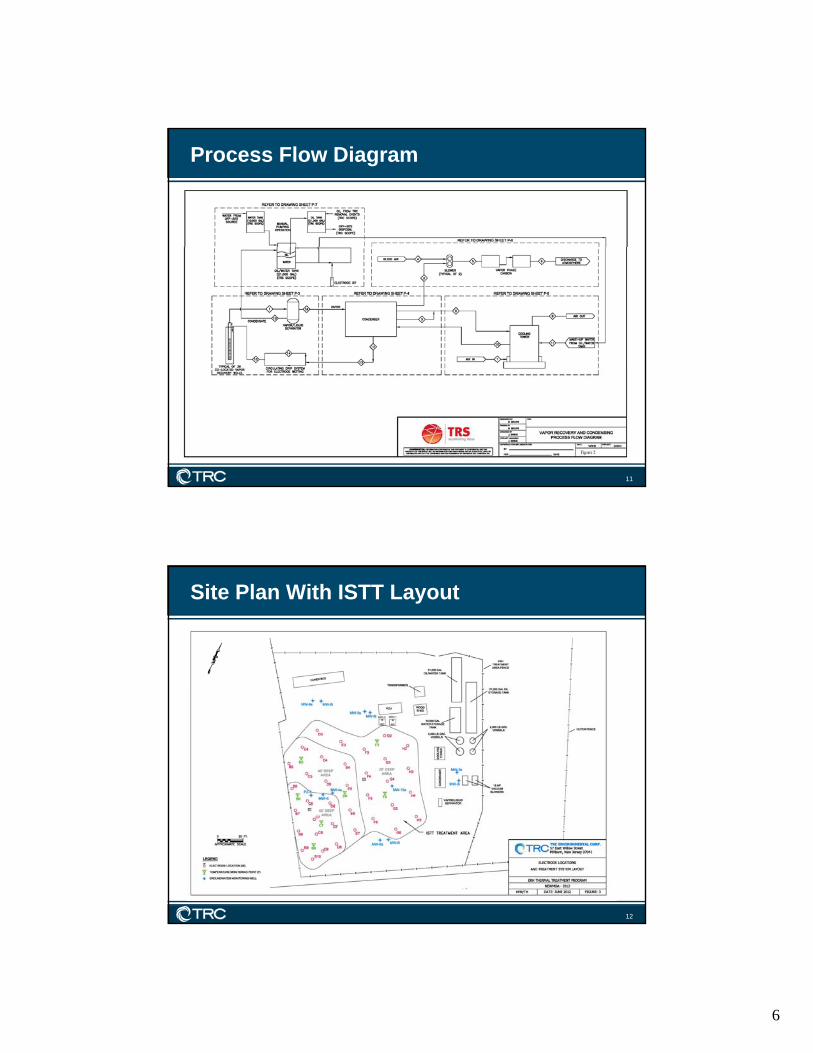
Process Flow Diagram
11
Site Plan With ISTT Layout
12
7
Site Views
Below: Electrode field in the snow
13
Above: Electrical Control Equipment and Power Supply
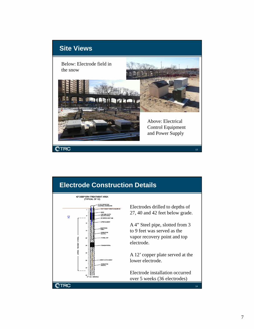
Electrode Construction Details
Electrodes drilled to depths of 27, 40 and 42 feet below grade.27, 40 and 42 feet below grade.
A 4” Steel pipe, slotted from 3 to 9 feet was served as the vapor recovery point and top electrode.
14
A 12’ copper plate served at the lower electrode.
Electrode installation occurred over 5 weeks (36 electrodes)

8
Electrode Photos
15
Above: Conductive Backfill Material (Graphite)Right: Electrode before connections and capping
Getting Hot – Increasing Temperatures
Subsurface Temperatures v. Time and Depth
16

9
Vapor Control
• Extracted vapors were treated using an array of GAC vessels.
• Approximately 30,000 lbs of spent, non-hazardous GAC were consumed during the project.
Alt t t i t t l t h l i ld h b d– Alternate contaminant control technologies could have been used, including the C3 technology and oxidation.
– The use of an oxidation technology would have required pH neutralization due to the presence of chlorine in contaminant.
• Influent and effluent air samples were collected to assess contaminant removal and emission control.
• Ambient air monitoring program was implemented during active ISTT operation to assess potential impacts on local air quality.
• Additional site ambient air surveys were conducted using a sensitive PID (PPB RAE), to identify any sources of air quality impacts on a live basis.
17
Vapor Control - GAC
Early Morning GAC Vessel Delivery
18
Insulated GAC Vessels(2x 5,000 lb vessels and 2x 2,000 lb vessels)

10
Hot Water/Product Safety
•Product gauging was conducted periodically through the system operation. •Gauging operation required lock-out/tag-out
•Incorporation of a full length heavy rain coat, heat resistant gloves and hard hat with face
of electricity to the field, and manual gauging for product.•All hot work required extra PPE.
19
shield were required during all “hot” work.•Ice Baths were incorporated in soil and groundwater sampling programs.
Contaminant Removal Rates
Removal rates peakedrates peaked at over 2.0 lbs/hour in February
283 Days of operation,
20
average flow rate of 390 CFM

11
Cumulative Mass Removal
Over 3,200 lbs of VOCs removed from the site;removed from the site;2,800 lbs of TCE (equivalent to ~230 gallons of pure product)
VOC groundwater concentrations reduced over 99.99%
21
Success!
22

12
Petroleum Remediation
• No separate phase product recovered or observed during treatment duration.
• BTEX compounds were removed during operation• BTEX compounds were removed during operation, however relatively low concentrations were often masked by high TCE and cis-1,2 DCE concentrations in influent air samples.
• Treatment program was able to demonstrate that remaining petroleum product was sufficiently stripped of volatile components and rendered immobilevolatile components, and rendered immobile.
• Post treatment soil samples did not show concentrations of BTEX compounds exceeding RSCO standards.
• Active product recovery event did not accumulate any free phase petroleum.
23
Continued Biodegradation
• Post treatment sampling (90 days after heating stopped) indicated population of TCE degrading bacteria were still present in the on-site groundwaterbacteria were still present in the on-site groundwater.
• ISTT did decrease microbial population, but did not sterilize the groundwater.
• Remaining dechlorinating bacteria are in an ideal geochemical environment for continued reductive dechlorination.
G d t OPR i t l ti– Groundwater OPR is strongly negative.
– Dissolved oxygen concentrations remained depressed after heating stopped.
• Removal of source area should expedite bioremediation of residual dissolved CVOC impacts.
24

13
Lessons Learned
• Get permits early – air permitting was a critical path item
• Prepare for water management
– Storage or discharge options need to be worked outStorage or discharge options need to be worked out prior to startup.
– Shallow groundwater and humid recovered vapors can lead to high water production rates.
• Prolonged peak contaminant recovery during thermal treatment may require alternate vapor treatment technologiestechnologies.
• Site security requirements are necessary during the entire project implementation.
• Groundwater temperatures remain elevated for long duration after completion.
25
Project Team
Special Thanks to the Project Team
• TRC Team:
Nidal Rabah PhD PE LSRP– Nidal Rabah, PhD, PE, LSRP
– Yasemin Kunukcu, PhD
– Brian Ross
– Audra Safter-Myers
– Kevin Lau
• TRS Team:TRS Team:
– Jeffery Brink, PG
– Chris Blundy
– Bradley Morris
– Jacob Seaman26

14
Thank You
• Take Away Points:
– ERH/ISTT is a viable option, but at higher costs.p g
– Health and Safety are paramount in ISTT programs
– ISTT allowed for rapid remediation, with quantifiable results in meeting remedial cleanup goals
– 9 months of active operation removed over 3,200 lbs of VOCslbs of VOCs
– Total project costs of approximately $2.3MM, but placed the project well on the path to closure.
• Questions?
27