university of south florida - usfsoar.com
TRANSCRIPT
University of South Florida
NASA Student Launch
Proposal
September 30, 2016
Society of Aeronautics and Rocketry
14247 Les Palms Circle, Apt. 102
Tampa, Florida 33613
2 Society of Aeronautics and Rocketry
Table of Contents
1. General Information ............................................................................................................4
1.1 Educator Information ....................................................................................................4
1.2 Safety Officer ..................................................................................................................4
1.3 Student Team Leader ....................................................................................................4
1.4 Web Presence ...............................................................................................................4
1.5 Project Organization......................................................................................................5
1.6 NAR/TRA Sections...........................................................................................................5
2. Facilities & Equipment .........................................................................................................6
2.1 Facilities/Equipment.......................................................................................................6
2.2 Personnel .........................................................................................................................7
2.3 Computer Programs ......................................................................................................8
2.3.1 Communication ...................................................................................................8
2.3.2 Design/Analysis .....................................................................................................8
2.3.3 Document Development ....................................................................................9
2.4 Supplies ...........................................................................................................................9
2.4.1Rocket Supplies and Materials ............................................................................9
3. Safety ..................................................................................................................................10
3.1 Safety Plans ...................................................................................................................10
3.1.1 Safety and Hazard Analysis ..............................................................................10
3.1.2 Safety Officer Responsibilities and Duties .......................................................16
3.2 NAR/TAR Personnel ......................................................................................................17
3.3 Safety Briefing ...............................................................................................................18
3.3.1 Hazard Recognition...........................................................................................18
3.3.2 Accident Avoidance ........................................................................................19
3.3.3 Launch Procedures ...........................................................................................19
3.4 Caution Statements.....................................................................................................20
3.5 Legal Compliance .......................................................................................................20
3.6 Purchase/Transportation/Storage of Motor .............................................................20
3.7 Written Statement of Compliance ............................................................................21

3 Society of Aeronautics and Rocketry
4. Technical Design ...............................................................................................................21
4.1 Vehicle Specifications .................................................................................................21
4.2 Projected Altitude ........................................................................................................22
4.3 Projected Parachute System......................................................................................23
4.4 Projected Motor ...........................................................................................................23
4.5 Projected Payload .......................................................................................................23
4.6 Requirements................................................................................................................25
4.6.1 Launch Vehicle Requirements ..........................................................................25
4.6.2 Recovery System Requirements .......................................................................25
4.6.3 Payload Requirements .......................................................................................25
4.7 Major Technical Challenges and Solutions ..............................................................26
5. Educational Engagement ................................................................................................27
6. Project Plan ........................................................................................................................28
6.1 Schedule .......................................................................................................................28
6.2 Budget ...........................................................................................................................29
6.3 Funding Plan .................................................................................................................29
6.4 Sustainability .................................................................................................................29

4 Society of Aeronautics and Rocketry
1. General Information
1.1 Educator Information
Dr. Manoug Manougian
Professor & Director of the STEM Education Center University of South Florida
(813) 974-2349
1.2 Safety Officer
Brooke Salas
Junior Undergraduate
Mechanical Engineering Major
1.3 Student Team Leader
Andrew Huff
Senior Undergraduate
Mechanical Engineering Major
(321) 848-4151
1.4 Web Presence
facebook.com/usfsoar
usfsoar.com

5 Society of Aeronautics and Rocketry
1.5 Project Organization
Figure 1 depicts the hierarchy of each leadership posit ion and overall team
structure.
Figure 1. Project Organization Chart
1.6 NAR/TRA Sections
The Society of Aeronautics and Rocketry at the University of South Florida Team
will ut ilize the nearby rocketry sections as a source of mentoring, launch
assistance, and reviewing. The local Tampa Tripoli Rocketry Associat ion
(prefecture #17) will be the high powered launch sites. In addit ion, the TTRA
location has an alt itude waiver of 12,000 feet.

6 Society of Aeronautics and Rocketry
2. Facilities & Equipment
2.1 Facilities/Equipment
USF Design for X Labs
An engineering lab space dedicated to providing space and tools for
engineering organizat ions and students. This location contains work tables, laser
cutters, 3D printers, and small hand tools. Construct ion and planning will happen
at this location.
Equipment:
- Small Hand Tools
- 3D Printers
- Laser Cutters
- Lathe
Hours: 7:00am - 5:00pm Monday - Friday
CUTR 102
A classroom reserved for weekly general body meetings and individual sections
of the rocket team.
Equipment:
- White Board
- LCD Projector
Hours: 5:00pm - 7:00pm

7 Society of Aeronautics and Rocketry
Offsite Workshop
Equipment:
- Lathe/Mill
- Power Tools
Varn Ranch (Plant City)
Varn Ranch is the official Tampa Tripoli Rocket Associat ion launch site, and also
where SOAR has launched most of its rockets. This will be the primary site for our
test launches. The site has a 10,000ft ceiling, allowing enough overhead for test
launches of the goal alt itude. Though we have much of the equipment we
need to launch, there is also equipment available on site to use as well.
Equipment:
- Launch Rails
- Dedicated Launch System
2.2 Personnel
Dr. Manoug Manougian
Dr. Manougian is Director of the University of South Florida’s STEM Education
Center and a dist inguished Professor of Mathematics. Dr. Manougian is the
organizat ion’s advisor, serving the students as a reference for rocket design,
construct ion, and launching of rocket propulsion systems. He also serves as a
role model and scient ific inspirat ion for the entire student body.
Jim West
Jim West is an experienced member of the hobby rocketry community and
local Tampa TRA. He oversees launches at Varn Ranch on Tripoli launch days

8 Society of Aeronautics and Rocketry
and has acted as a mentor in terms of design and manufacturing of our rockets,
part icularly high powered designs.
2.3 Computer Programs
2.3.1 Communication
Outside of regular meeting t imes, team communication is achieved primarily
through the Slack messaging app and also by email, our website, and text ing
among the officers and team members. An updated roster on USF’s campus
engagement network “Bullsync” will consistent ly keep the email list up to date
and ensure that everyone knows the status of the ongoing project.
2.3.2 Design/Analysis
Our team will ut ilize the 3D rendering software SolidWorks 2015-2016, which is
provided free of charge by the University of South Florida to all students through
the application gateway. ANSYS Simulat ion Software is another resource that will
be employed, and it is also available to all students. These softwares will allow
the team to draft feasible mechanical models as well as engineering analysis
simulat ions.
The USF application gateway also provides students with access to MATLAB, a
resource that will prove invaluable for data processing and mathematical
modelling.
Addit ionally, for precision rocket predict ion and simulat ion we will use a
combination of RockSim, a well-known commercial design and simulat ion
program and OpenRocket, a java-based open-source, free-to-use program

9 Society of Aeronautics and Rocketry
designed for model rocket analysis. Correlat ion between these programs will
provide a model of best fit .
2.3.3 Document Development
For document development, as well as data storage, our team intends to use
our pre-exist ing organizat ional cloud storage, the SOAR Google Drive. This
database allows us to instantaneously communicate and work collaboratively
on documents and presentations.
2.4 Supplies
2.4.1 Rocket Supplies and Materials
Nose cone Public Missiles - FNC-6.00 - Fiberglass nose cone, Material:
Fiberglass
Body tube - Custom, Material: Fiberglass
Main Parachute b2 Rocketry - CERT-3 XLarge - SkyAngle, Material: 1.9 oz.
Ripstop Nylon (SkyAngle)
Alt imeter Bay - Custom, Material: Fiberglass
Tube coupler - Custom, Material: Kraft phenolic
Alt imeters and Batteries - Custom, Material: Custom
Bottom Drogue Parachute b2 Rocketry - CERT-3 Drogue - SkyAngle,
Material: 1.9 oz. Ripstop Nylon (SkyAngle)
Drogue Parachute b2 Rocketry - CERT-3 Drogue - SkyAngle, Material: 1.9
oz. Ripstop Nylon (SkyAngle)
Fin set - Custom, Material: G10 (PML 0.062")
Body tube Public Missiles Ltd. - KS-3.0-GIANT - Giant KwikSwitch MMT
75mm, Material: Kraft phenolic
10 Society of Aeronautics and Rocketry
Bulkhead - Custom, Material: 1/8 Aircraft Plywood
Removable Bulkhead - Custom, Material: 1/8 Aircraft Plywood
Quicklink, Material: Steel
Shock Cord, Material: Kevlar
Forged Eye-Bolts, Material: Steel
3. Safety
Safety is paramount in the Society of Aeronautics and Rocketry and the
University of South Florida in its ent irety. While our Safety Officer actively ensures
the well-being of members and property, our ent ire team is expected to
maintain constant vigil. We brief all members of the potential hazards in our
projects and encourage them to voice any concerns.
3.1 Safety Plans
3.1.1 Safety and Hazard Analysis
Careful observation regarding the team members, rockets, payload components, and
work and launch environment has been done and any hazards observed have been
addressed. Each potential hazard has received a risk assessment level using the risk
assessment matrix found on page 56 of the NASA Student Launch Handbook. Risk levels
are determined by the severity of the potential situations and the probability the
hazards will occur.
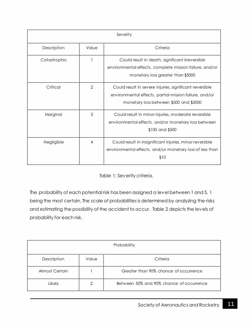
The severity of each potential risk is determined by comparing the possible outcome to
criteria based on human injury, vehicle and payload equipment damage, and
damage to environment. Severity is based on a 1 to 4 scale, 1 being the most severe.
The severity criteria is provided below in Table 1.
11 Society of Aeronautics and Rocketry
Severity
Description Value Criteria
Catastrophic 1 Could result in death, significant irreversible
environmental effects, complete mission failure, and/or
monetary loss greater than $5000
Critical 2 Could result in severe injuries, significant reversible
environmental effects, partial mission failure, and/or
monetary loss between $500 and $5000
Marginal 3 Could result in minor injuries, moderate reversible
environmental effects, and/or monetary loss between
$100 and $500
Negligible 4 Could result in insignificant injuries, minor reversible
environmental effects, and/or monetary loss of less than
$10
Table 1: Severity criteria.
The probability of each potential risk has been assigned a level between 1 and 5, 1
being the most certain. The scale of probabilities is determined by analyzing the risks
and estimating the possibility of the accident to occur. Table 2 depicts the levels of
probability for each risk.
Probability
Description Value Criteria
Almost Certain 1 Greater than 90% chance of occurrence
Likely 2 Between 50% and 90% chance of occurrence

12 Society of Aeronautics and Rocketry
Moderate 3 Between 25% and 50% chance of occurrence
Unlikely 4 Between 1% and 25% chance of occurrence
Improbable 5 Less than 1% chance of occurrence
Table 2: Probability scale
Risk assessment levels are then assigned based on the severity and probability levels. By
following the given risk assessment matrix, each hazard has been assessed and further
observation into each hazard is being considered. For each risk, mitigation has been
detailed. Throughout the progression of the project, new risks will arise, and will be
considered. Completed risk assessments are found below in Table 3.
Hazard Severity of
Risk
Probability
of Risk
Risk Level Mitigation
Using
power
tools
3 3 Low 1. All individuals to use tools with
be trained on each tool. No
individual will attempt to learn
how to use the tool on their own
and no individual will use the
tool who is not trained on that
tool. Safety glasses will be worn
at all times within the lab and
workshop. Lab and workshop will
be kept clean and cleaned
after each use to ensure no
debris is left that may cause
injury
2. Any additional PPE will be
worn as instructed by the tool

13 Society of Aeronautics and Rocketry
manufacturer or as required. All
individuals will be instructed on
proper use of PPE
Working
with
chemical
componen
ts
3 4 Low 1. MSDS documents will be
readily available at all times for
all chemicals. MSDS documents
will be reviewed before each
use of chemicals. Gloves and
safety goggles designed for
chemical splash will be worn at
all times by all personnel when
working with and/or near
hazardous chemicals
2. When working with chemicals
that will generate fumes all work
is to be done in a well-ventilated
area. All personnel will minimize
inhalation by wearing
appropriate PPE which may
include vapor masks when there
is a risk of serious fume inhalation
Motor
ignition
failure
1 3 Moderate 1. Follow TRA safety code and
wait a minimum of 60 seconds
before approaching the rocket
to ensure that the motor is not
just delayed in launching.
2. If there is no activity after 60
seconds, the safety officer will
check the ignition system for a
lost connection or a bad igniter.
3. In the event of a faulty
ematch, the safety officer or

14 Society of Aeronautics and Rocketry
project manager will remove the
ignition system from the rocket
motor, retrieve the motor from
the launch pad and replace the
motor with a spare.
Motor
explodes
upon
ignition on
the launch
pad
1 4 Moderate 1. Assure that all team members
are a safe distance away from
the launch pad upon ignition of
the rocket.Wait a specified
amount of time before
approaching the pad after a
catastrophe. All fires will be
extinguished when it is safe to
approach the pad.
Separation
of rocket
at apogee
and/or
500ft does
not occur
1 3 Moderate 1. Separation sections of
rocket will be designed to
ensure that the black powder
charges provide enough
force to cause the pins to
shear. Ground test will be
done to ensure the correct
amount of black powder is
used
2. Couplings between
components will be sanded
to prevent components from
sticking together. Fittings will
be tested prior to launch to
ensure that no components
are sticking together

15 Society of Aeronautics and Rocketry
In the event that the rocket
does become ballistic, all
indiv iduals at the launch field
will be notified immediately
Parachute
does not
deploy
1 3 Moderate 1. The packing of each
parachute will be checked by
our mentor prior to launch to
ensure proper packing. In
addition the parachute size has
been selected to fin within the
body tube but not so tightly as to
become stuck due to the size of
the parachute.
In the event that the rocket does
become ballistic, all individuals
at the launch field will be
notified immediately
Altimeter
and/or e-
match
failure
1 4 Moderate 1. We will have a redundancy by
including two altimeters each
with their own e-matches and
black powder charges, wired in
series.
In the event that the rocket does
become ballistic, all individuals
at the launch field will be
notified immediately
Table 3: Risk Assessment and Mitigation

16 Society of Aeronautics and Rocketry
3.1.2 Safety Officer Responsibilities and Duties
As mentioned, all members are expected to maintain awareness of the
potential dangers. However, we have nominated Brooke Salas to be our official
Safety Officer. Brooke has earned this role through constant dedication to our
organizat ion as well as consistent procedural vigilance. When the safety officer
is not available, we will turn to our Student Team Leader to oversee the
maintenance of safety.
The roles and responsibilit ies of the safety officer include, but are not limited to:
A. Monitor all team activities with an emphasis on safety, including:
Design of launch vehicle
Creation of launch vehicle
Set-up of launch vehicle
Exhaust ive ground test ing of launch vehicle
Subscale launch test(s)
Full-scale launch test(s)
Competit ion activities and launch
Recovery activities
Educational engagement activit ies
B. Coordinate and implement the safety procedures out lined by the
organizat ion for the design, creation, set -up, launch, and recovery of the
launch vehicle.
C. Finding the relevant Material Safety Data Sheets (MSDS), sharing them with
organizat ion, and maintaining the appropriate folder in the organizat ion’s
Google Drive, Material Safety Data Sheets. The Safety Officer will also ensure

17 Society of Aeronautics and Rocketry
proper and safe condit ions of materials during storage, t ransport, and
implementation.
D. Analyze and record the team’s hazard analysis tests, failure mode analysis,
simulat ions, experimental data, and other relevant information sources for
failures and potentially hazardous trends. As well as coordinating the
compliance with safety procedures and improvements to reduce risk.
E. Assist in the management and development of the team’s hazard analysis,
failure mode analysis, safety simulat ions, safety procedures, and guidelines.
F. Maintaining responsible and appropriate organizat ional behavior at all stages
of design, development, test, t ravel, and launch.
G. Finally, the safety officer is expected to familiarize herself with all local, state,
and federal laws, rules, customs, and regulat ions which apply to the use and
transportation of motors, propellants, and other sources of risk. Based on this
familiarity, the safety officer is expected to ensure compliance with the
aforementioned regulat ions.
3.2 NAR/TAR Personnel
The following launch procedure will be followed during each test launch. This
procedure is designed to outline the responsibilit ies of the NAR/TRA Personnel
and the members of the team.
1. A level 2 cert ified member and an NAR/TRA Personnel will oversee any
test launch of the vehicle and flight tests of the vehicle.
2. The launch site Range Safety Officer will be responsible for ensuring proper
safety measures are taken and for arming the launch system.

18 Society of Aeronautics and Rocketry
3. I f the vehicle does not launch when the ignit ion button is pressed, then
the RSO will remove the key and wait 90 seconds before approaching the
rocket to invest igate the issue. Only the Project Manager and Safety
Officer will be allowed to accompany the RSO in invest igating the issue.
4. The RSO will ensure that no one is within 100 ft . of the rocket and the team
will be behind the RSO during launch. The RSO will use a 10 second
countdown before launch.
5. A cert ified member will be responsible for ensuring that the rocket is
directed no more than 20 degrees from vert ical and ensuring that the
wind speed is no more than 5 mph. This individual will also ensure proper
stand and ground condit ions for launch including but not limited to
launch rail length, and cleared ground space. This member will ensure
that the rocket is not launched at targets, into clouds, near other aircraft,
nor take paths above civilians. Addit ionally, this individual will ensure that
all FAA regulat ions are abided by.
6. Another cert ified member will ensure that flight tests are conducted at a
cert ified NAR/TRA launch site.
7. The safety officer will ensure that the rocket is recovered properly
according to Tripoli and NAR guidelines.
3.3 Safety Briefing
3.3.1 Hazard Recognition
The team Safety Officer will orchestrate all potentially hazardous activit ies, as
well as brief the members who may part icipate in such activities on proper
safety procedures, and ensuring that they are familiar with any personal
protective equipment which must be worn during those activities. If a member
fails to abide by the safety procedures, he/she will not be permitted to

19 Society of Aeronautics and Rocketry
part icipate in the potentially hazardous activit ies. In addit ion to briefing the
members on safety procedures, the team Safety Officer must remain in the
immediate vicinity of the hazardous activity as it is occurring, so as to mit igate
any potentially dangerous incidents and answer any safety quest ions which
may arise.
3.3.2 Accident Avoidance
I t will be the duty of the team Safety Officer to verify, in advance, that
procedures planned for test ing or construct ion of materials by team members
sat isfy safety requirements. In the event that the Safety Officer judges a planned
procedure to be unsafe, said procedure will thus be revised or eliminated.
3.3.3 Launch Procedures
At the team meeting most closely preceding the launch, the Safety Officer will
be given t ime to help the members review launch safety and precautionary
measures. Topics discussed at this t ime include but are not limited to: laws and
regulat ions mandated by the Federal Aviation Administration (FAA), the
National Fire Protection Associat ion (NFPA), and Florida State Statutes;
prohibited launchpad activities and behaviors; maintaining safe distances; and
safety procedures pertaining to any potentially hazardous chemicals which will
be present during the launch. All team leaders must be in attendance at this
briefing, and they are obliged to address the other members with any further
safety concerns they are aware of that were not mentioned by the Safety
Officer. At this t ime, launch procedures will be scrut inized, paying special
attention to the parts involving caution.

20 Society of Aeronautics and Rocketry
3.4 Caution Statements
Any potential safety hazards or concerns that may arise throughout the course
of this project will be documented where relevant. To minimize risks the design
verification process will include a comprehensive invest igation to ensure safety
in manufacturing, test ing, and launching of our rocket. The Safety Officer and
Project Manager will present at all design verification meetings.
3.5 Legal Compliance
The Safety Officer and Project Manager have read all relevant laws and
regulat ions that apply to this project in order to ensure compliance with these
laws. As well, the team members will also be briefed on these laws as they apply
to the project. The material reviewed includes:
- 14 CFR: Aeronautics and Space, Chapter 1, Subchapter F, Part 101,
Subpart C: Amateur Rockets
- 27 CFR: Part 55: Commerce in Explosives
- Florida Statute: Title XXV: Aviation, Chapter 331: Aviation and Aerospace
Facilit ies and Commerce
- Florida Statute: Title XXXII I : Regulat ion of Trade, Commerce, Investments,
and Solicitat ions, Chapter 552: Manufacture, Distribut ion, and Use of
Explosives
- NFPA 1127 “Code for High Power Rocket Motors”
3.6 Purchase/Transportation/Storage of Motor
The motor will be purchased and stored by one of our organizat ion’s mentors.
This person is cert ified for the purchase of high powered rocket propellent and

21 Society of Aeronautics and Rocketry
well versed in storage. The propellent will be stored in an off-campus garage,
where several other rocket components have been stored carefully. There will
be a clear indication that there is propellent in the room, by large lettering on
the magazine and yellow/black cautionary tape. There will also be a clear
indication to keep away, in addit ion to warning about fire in the area. Our
mentor shall maintain primary access to the propellent upon storage and shall
prep it for t ransportation. It will be secured carefully within a vehicle, bound
down to avoid unnecessary motion and without the risk of any other object
rest ing or falling on top of it .
3.7 Written Statement of Compliance
All members of the team agree to abide by all relevant laws and regulat ions set
forth by the FAA, NFPA, and NASA. The team agrees to have the launch site
Range Safety Officer perform a safety inspection before each flight and to
comply with the determinations from the RSO’s safety inspections. All members
recognize that the RSO will determine all final decisions regarding rocket safety
and that this individual has the right to deny the launch of any rocket for safety
reasons. As well all members recognize that noncompliance with the RSO’s
requests will result in the team being unable to launch the rocket.
4. Technical Design
4.1 Vehicle Specifications
The proposed design is shown below. It is 145 inches in length and 6 inches in
diameter. The body tubes are made out of fiberglass with kraft phenolic motor

22 Society of Aeronautics and Rocketry
mount. The fins are G10 fiberglass. We chose fiberglass because of it’s high
tensile and compressive strengths as well as its availability.
To construct the rocket we will begin with the fin can. We will epoxy the fins onto
the motor mount with chopped carbon fiber in the epoxy for added strength.
Once that is complete we will cut slits in the outer tube and slide the fin can into
the aft fiberglass tube. We will add fillets with epoxy on the outer and inside of
the outer tube for increased stability of the fins.A bulkhead will be added to the
end of the motor mount to hold the motor mount in place. Above this bulkhead
is where the landing mechanisms will be placed. Above the mechanisms will be
a removable bulkhead with a forged eyebolt on it to attach to the parachutes.
4.2 Projected Altitude
The projected alt itude is 5,400 feet on an L class motor. Simulat ions of launch
data was completed using Rocksim. We have found that the weights for the
rocket components in Rocksim are lower than what it will actually be. This is
because we, as an organizat ion, usually add more epoxy for safety reasons. This
will, in theory, lower our projected alt itude. The rocket was modeled in Rocksim
and several different motors were tested on it up to an L class motor. Once
each part of the rocket is built we can update the mass of our rocket to get a
more approximate model of ascent and apogee.

23 Society of Aeronautics and Rocketry
4.3 Projected Parachute System
At apogee the alt imeter will blow the bottom section of the rocket off with two
drogue parachutes. It will push out the parachute for the bottom section and
the drogue for the rest of the rocket. The bottom section will be separate from
the rest of the rocket and this section will be the one to land on the target. The
bottom section’s parachute will be attached to a forged eyebolt in the
bulkhead. The other section of the rocket will have the parachute and shock
cord attached to a forged eyebolt in at the alt imeter bay. At 800 feet the main
parachute with shock cord will deploy to slow descent and land safely.
4.4 Projected Motor
The motor selected is a L1100 from Animal Motor Works. The motor has a 75 mm
diameter and a length of 72.8 cm. The average thrust is roughly 1100 N, and the
total impulse is roughly 2600 N-s with a 2.3 second burn t ime.
4.5 Projected Payload
The teams projected payload will consists of a flap design, designated to detect
the projected landing platform on descent and land vert ically upright. The flap
system will be located on the lower stage of the rocket for vert ical landing
purposes. Our system will consist of four flaps, four servo motors, a pixy color
sensor and an accelerometer. The system will communicate with an arduino to
accomplish the experimental goal.
24 Society of Aeronautics and Rocketry
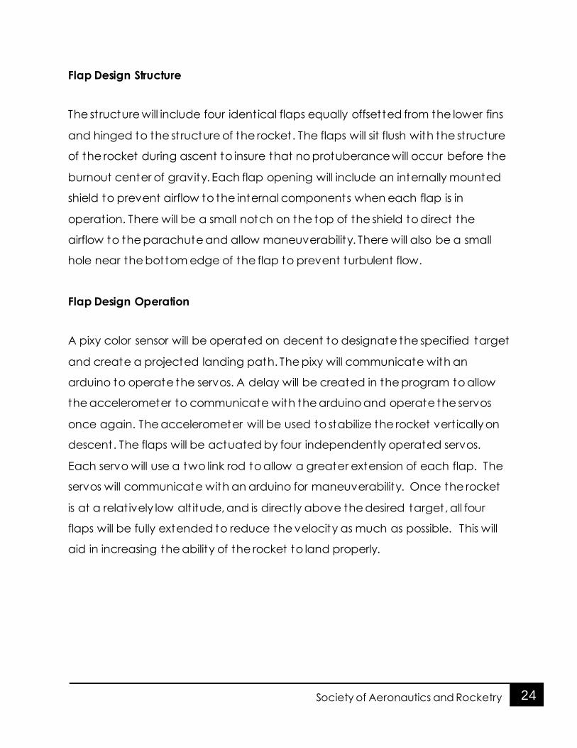
Flap Design Structure
The structure will include four identical flaps equally offsetted from the lower fins
and hinged to the structure of the rocket. The flaps will sit flush with the structure
of the rocket during ascent to insure that no protuberance will occur before the
burnout center of gravity. Each flap opening will include an internally mounted
shield to prevent airflow to the internal components when each flap is in
operation. There will be a small notch on the top of the shield to direct the
airflow to the parachute and allow maneuverability. There will also be a small
hole near the bottom edge of the flap to prevent turbulent flow.
Flap Design Operation
A pixy color sensor will be operated on decent to designate the specified target
and create a projected landing path. The pixy will communicate with an
arduino to operate the servos. A delay will be created in the program to allow
the accelerometer to communicate with the arduino and operate the servos
once again. The accelerometer will be used to stabilize the rocket vert ically on
descent. The flaps will be actuated by four independently operated servos.
Each servo will use a two link rod to allow a greater extension of each flap. The
servos will communicate with an arduino for maneuverability. Once the rocket
is at a relat ively low alt itude, and is direct ly above the desired target, all four
flaps will be fully extended to reduce the velocity as much as possible. This will
aid in increasing the ability of the rocket to land properly.

25 Society of Aeronautics and Rocketry
4.6 Requirements
4.6.1 Launch Vehicle Requirements
The launch vehicle will need to meet the following requirements:
Launch from 5 degree from vert ical
Fly straight with minimal drift ing
Attain an apogee of 5,280 feet
4.6.2 Recovery System Requirements
The recovery system will need to meet the following requirements:
Deploy all parachutes at the correct alt itude
Deploy fully and have the parachutes open quickly
Allow for minimal drift
Slow descent rate to attain a safe landing
4.6.3 Payload Requirements
The payload system will need to meet the following requirements:
Design an onboard camera system on a section of the rocket
Employ a logic system to different iate between the three colored target
zones
Deploy flaps to reduce descent velocity and correct upright orientat ion
Produce a controlled landing with reasonable proof

26 Society of Aeronautics and Rocketry
4.7 Major Technical Challenges and Solutions
Vehicle
One of the challenges involves the containment of the three parachute design,
ensuring all parachutes come out properly and do not tangle. The solut ion to
this is making sure the correct amount of black powder is used by the alt imeter
bay and carefully packing the parachutes, ensuring correct deployment.
Another challenge is ensuring the removable bulkhead for the landing
mechanism is easy to remove, yet strong enough to maintain its hold. A solut ion
to this is to implement metal inserts in the bulkhead allowing the bulkhead to be
mounted and removed.
Payload - Mechanical
The landing detection and upright landing experiment will induce a challenge
when it comes to the mechanical system’s design, functionality and safety
factors. In order to pursue the experimental goal, a stress and strain simulat ion
will be performed using a Fundamental Element Analysis (FEA) program. The
recorded data will then be used to determine the correct selection of
mechanical components and flap design. In order for this all to be
accomplished, the proper programming must be implemented, which will
possibly present the greatest challenge with this design. At any given t ime, the
rocket will need to recognize its orientat ion in flight, and autonomously adjust
itself at a precise magnitude to avoid drast ic changes in its flight pattern.

27 Society of Aeronautics and Rocketry
Payload - Electrical
This project will give us a unique new challenge for handling signal t ransmission
to our rocket. We will be working to ensure we get consistent communication
with our onboard systems, reducing latency and maintaining a design for our
alt imeter/electronics bay that befits proper signal t ransmission.
5. Educational Engagement
SOAR will conduct educational engagement activities with as many local
schools as possible. Two charter schools have been contacted already to
init iate planning of activities. We expect to have several students visit the
schools after their dismissal and work with the students who a part of the after-
school programs. In this sett ing, we’d be able to give the students the attention
they need to learn the material we teach.
We also have plans to part icipate in USF’s Engineering Expo which is the
largest annual engineering event on campus. In February, the event will host
thousands of elementary, middle, and high school students with demonstrations
by student engineering organizat ions, USF research labs, and engineering
companies. In this sett ing, we’ll engage a large amount of students during the
two-day event actively with hands-on activities and passively with information
about rocketry.

28 Society of Aeronautics and Rocketry
6. Project Plan
6.1 Schedule
Task Deadline
Proposal 9/30/2016
Initial Design:
10/15/2016
Rocket
Engineering Systems
Establish Budget 10/20/2016
PDR Report 10/31/2016
Prototype of eng systems 11/30/2016
Subscale fabrication 11/30/2016
Prototype testing 12/15/2016
Subscale test launch 12/17/2016
Final Design
12/20/2016
Rocket
Engineering Systems
CDR Report 1/13/2017
Fullscale fabrication 2/11/2017
Final fabrication of eng
systems 2/15/2017
Fullscale test launch 2/18/2017
FRR Report 2/28/2017
29 Society of Aeronautics and Rocketry
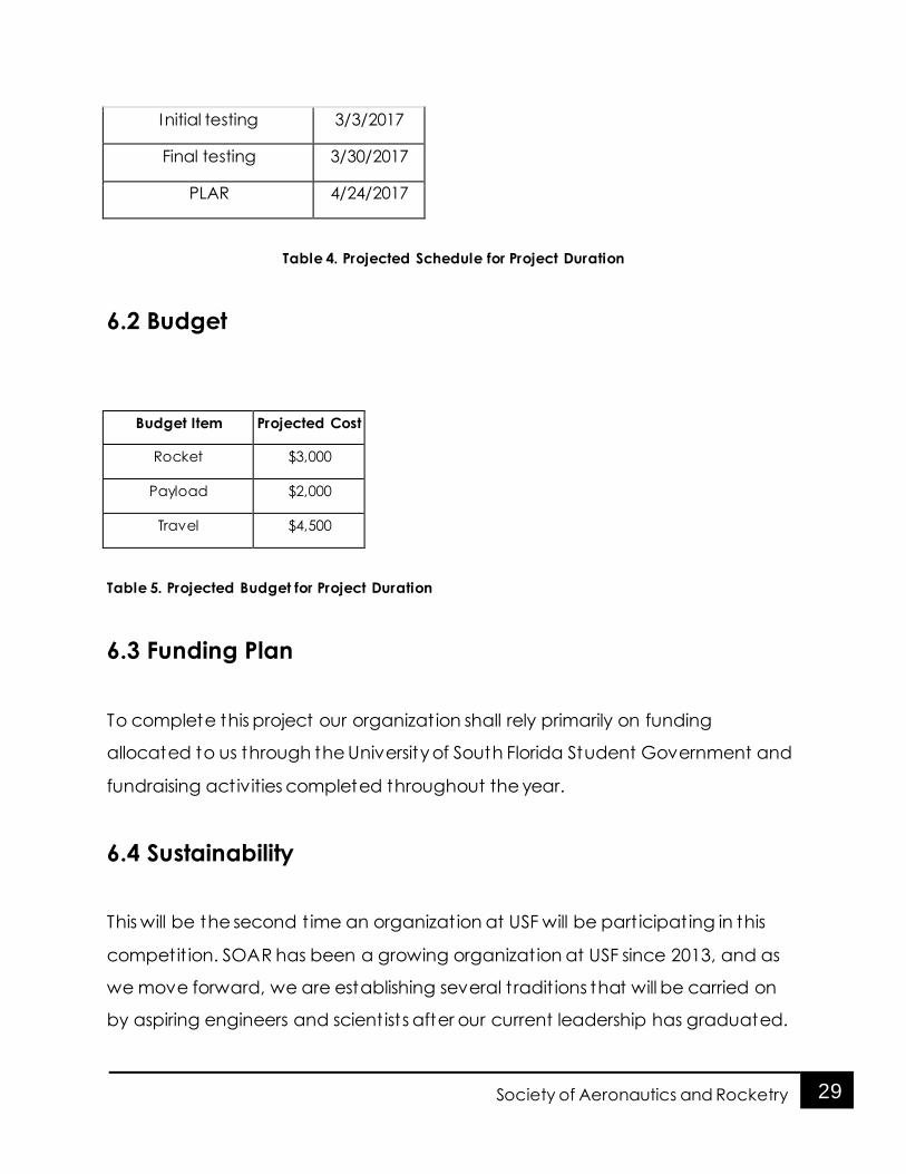
Initial testing 3/3/2017
Final testing 3/30/2017
PLAR 4/24/2017
Table 4. Projected Schedule for Project Duration
6.2 Budget
Budget Item Projected Cost
Rocket $3,000
Payload $2,000
Travel $4,500
Table 5. Projected Budget for Project Duration
6.3 Funding Plan
To complete this project our organizat ion shall rely primarily on funding
allocated to us through the University of South Florida Student Government and
fundraising activities completed throughout the year.
6.4 Sustainability
This will be the second t ime an organizat ion at USF will be part icipating in this
competit ion. SOAR has been a growing organizat ion at USF since 2013, and as
we move forward, we are establishing several t radit ions that will be carried on
by aspiring engineers and scient ists after our current leadership has graduated.

30 Society of Aeronautics and Rocketry
Every year our organizat ion gains new members who are willing to take on
leadership posit ions and help SOAR grow to be more effective.
As a student organization, we have developed a strong relat ionship with student
government based on a history of fiscal responsibility and adherence to
procedure. Our budget is consistent ly awarded annually due to our attention to
detail and a good relat ionship with the administration. Student Government
appreciates our organizat ion’s purpose and supports it . In addit ion to the
university connections, our organizat ion has long last ing relat ionships with our
mentors, who have supported us since the formation of the club.