university of hoxg kong library - hku librariesebook.lib.hku.hk/hkg/b35838504.pdf · university of...
TRANSCRIPT


UNIVERSITY OF HOXG KONGLIBRARY
Hong Kong CollectionGift from
Books Registration Ordinance

CODE OF PRACTICE
OVERALL THERMAL TRANSFER VALUE
IN BUILDINGS
1995
HONG KONG

CODE OF PRACTICE
FOR
OVERALL THERMAL TRANSFER VALUE
IN BUILDINGS
1995
BUILDING AUTHORITY
HONG KONG
April 1995

...IJL'LJ

Foreword
A consultancy study in 1991 that if the of a building was
constructed to a suitable overall thermal transfer value (OTTV),
from air-conditioning and thus the emission of greenhouse
could be reduced. The Government's aim is to establish a
energy code to control the total energy consumption of a building, of which OTTV
controls would form a part. As a first step, legislative control over OTTV has
introduced in the Building (Energy Efficiency) Regulation (Cap. 123 sub. leg.).
This Code of Practice provides technical guidance for authorized
persons, registered structural engineers and other persons responsible for the design
and construction of buildings. Compliance with the provisions in this Code may be
deemed to satisfy the requirement of a suitable OTTV for a building under the Building
(Energy Efficiency) Regulation.
This Code will be regularly reviewed. The Building Authority welcomes
suggestions for improving this Code or for enhancing the energy efficiency of buildings
in general.
Other options for achieving equivalent and better performance standards
are available and will of course be considered in isolation or in combination for the
purpose of establishing acceptability.

CONTENTS
Paragraph Page
1. General Principles of Control of Overall Thermal Transfer 1Value
2. Definitions 2
3. Suitable OTTV 3
4. Principles of OTTV Calculations 4
5. OTTV of External Walls 5
6. OTTV of Roofs 5
7. Calculation of Component Coefficients and Parameters of 6OTTV
8. Windows and Doors 17
9. Submission of Information 17
Schedule - Standard Forms
Appendix - A sample of OTTV calculations for a typical commercial building

I. General Principles of of
1.1 For the design and planning of energy - efficient is
developing a comprehensive energy code to cover alia and air-conditioning.
Overall thermal transfer value (OTTV) is one of conservation*
General approach
1.2 An OTTV is a measure of the energy consumption of a building envelope.
Its formulation allows authorized persons, registered structural engineers and other
persons responsible for the design and construction of buildings freedom to innovate and
vary important envelope components such as type of glazing, window size, external
shading to windows, wall colour and wall type to meet the maximum OTTV criteria.
Any measure to improve energy efficiency or to save energy should be considered in
planning a building.
1.3 Siting a building to avoid extensive glazed facades with a southerly aspect or
introducing shades to window areas can reduce solar heat gain. Appropriate choice of
windows with a low thermal transmittance characteristic will also minimize solar heat
transmission.
1.4 Artificial lighting consumes electricity and creates heat. This increases the
cooling load of a building and in turn increases energy consumption. Consequently,
when determining the size and location of windows as well as choice of glass in the
envelope of a building, efforts should be made to provide as much natural lighting into
the building as possible. For example, with glazing, the visible lighting transmittance
should be acknowledged in addition to its thermal transmittance properties; daylight can
supplement artificial lighting and consequently reduce the cooling load.
1.5 Other measures include more extensive use of energy-efficient building
services equipment and appliances, e.g. energy-saving lamps, low-loss luminaries and
high-efficiency air-conditioning and more sophisticated building services control systems.

Scope
1.6 The provisions in this Code apply to all hotels and commercial buildings as
defined in the Building (Energy Efficiency) Regulation. They aim at reducing heat
transfer through the building envelope and thus the electricity required for air-
conditioning.
1.7 The concept of OTTV is based on the assumption that the envelope of a
building is completely enclosed.
1.8 In the OTTV formulation, the following factors are not addressed or allowed
tor:
(a) Internal shading devices, such as draperies and blinds.
(b) Solar reflection or shading from adjacent buildings.
2, Definitions
In this Code, unless otherwise stated, words and expressions have the
meaning attributed to them by the Building (Energy Efficiency) Regulation. It should
also be noted that:
''building tower11 means that part of a building above the podium of the building;
"fenestration* means any glazed aperture in the building envelope;
"lightweir means a vertical shaft of open air enclosed on all sides by parts of a building;
''opaque* wall or roof means that solid part of the wall or roof which is not part of the
fenestration;

"podium" means that part of a building which,
(a) if having a site coverage exceeding the permitted percentage site coverage,
is -
(i) within 15 m above ground level as permitted under Building (Planning)
Regulation 20(3); or
(ii) within such height as is permitted by the Building Authority by way
of a modification of that regulation granted under section 42 of the
Buildings Ordinance; and
(b) if having a site coverage within the permitted percentage site coverage, is
within 15 m above ground level.
"refuge floor" has the meaning assigned to it in the Code of Practice for Means of Escape
and means a protected floor that serves as a refuge for the occupants of the building
to assemble in case of fire.
3. Suitable OTTV
3.1 The external walls and roofs of a building to which the Building (Energy
Efficiency) Regulation applies should be designed and constructed to have the following
OTTV :
(a) in the case of a building tower; the OTTV should not exceed 35 W/m?; and
(b) in the case of a podium; the OTTV should not exceed m W/irfL
3.2 The maximum OTTV specified in paragraph 3.1 should apply to the overall
building envelope, i.e. all the external walls and roofs, as the case may be, in average
and do not apply to the individual wall or roof.

3.3 The OTTV of the external walls and roofs of a building tower or podium
should be assessed In accordance with methods set out in this Code. A sample of OTTV
calculations for a typical commercial building is set out in Appendix for illustration.
4. Principles of OTTV Calculations
External walls and roofs not included in OTTV calculations
4.1 All external walls and roofs of a building should be included in OTTV
calculations except -
(a) an external wall of a refuge floor;
(b) an external wall or roof of a carparking floor;
(c) an external wall of a lightwell having an area on plan not exceeding 21 m2; and
(d) any wall on any roof.
Party wall
4.2 An external wall of a building which is a party wall should-be included in
OTTV calculations whether an adjoining building exists or not. Shading to the party wall
from adjoining buildings should not be considered in calculating the OTTV.

5. OTTV of
The OTTV of the external walls of a building tower or a podium, OTTVW> be
calculated using the following formula -
(Aw x U x a x TDEQw) + (Afw x SC x x SF)OTTVW =
Aow
where
Aw = Area of opaque wall, m2
U = Thermal transmittance of opaque wall, W/m2°C (See 7.1)
a = Absorptivity of the opaque wall (Table 4)
TDgQw = Equivalent temperature difference for wall, °C (Table 5)
Afw = Area of fenestration in wall, m2
SC = Shading coefficient of fenestration in wall (See para 7.5)
ESM = External shading multiplier (Table 6 and 7)
SF = Solar factor for the vertical surface, W/m2 (Table 8)
Aow = Gross area of external walls, i.e. Aw + Afw, m2
6. OTTV of Roofs
The OTTV of the roofs of a building tower or a podium, OTTVr> should be calculatedusing the following formula :-
(Ar x U x a x TDEQr) + (Afr x SC x SF)OTTVr =
Aor
Where
Ar = Area of opaque roof, m2
U = Thermal transmittance of opaque roof, W/m2°C (See para 7.1)
a = Absorptivity of the opaque roof (Table 4)
TDEQr= Equivalent temperature difference for roof, °C (Table 9)
Afr = Area of fenestration in roof, m2
SC = Shading coefficient of fenestration in roof (See para 7.5)
SF = Solar factor for horizontal surface, W/m2 (Table 8)
= Gross area of roof, i.e. Ar + Afr, m2

6 -
7. Calculation of Component Coefficients and Parameters of OTTV
Thermal transmittance of opaque construction (U)
7.1 Opaque walls and roofs usually involve a composite of materials. Thethermal transmittance of an opaque wall or roof should be derived by the followingformula :
1U = ;
xi X2 xn
ki k2 kn
x = Thickness of building material of the wall or roof or part thereof, m
k = Thermal conductivity of the building material, W/m°C(Table 1)
Rj = Surface film resistance of internal surface of the wall or roof, m2°C/W(Table 2)
RO = Surface film resistance of external surface of the wall or roof, m2°C/W(Table 2)
Ra = Air space resistance, m2°C/W (Table 3)
Component coefficients and parameters of thermal transmittance
7,2 The component coefficients and parameters used in calculating the thermaltransmittance of opaque construction should be assessed as follows :
(a) Thermal conductivity of building materials (k)
The thermal conductivity of the building materials of walls and roofs should beobtained from Table 1.

Table 1 Thermal Conductivity of Building Materials
Material
Asphalt, mastic with 20% grit
Boardsa) corkb) hardboard high densityc) mineral fibred) plasterboard
Brick (common)
Concretea) normal weight aggregateb) lightweight aggregatec) flat roof tiles or slabs
Glass
Mosaic tile cladding
Insulating materialsa) glass fibre mat or quiltb) mineral wool feltc) polystyrene expandedd) polyurethane foam
Metalsa) aluminium alloy typicalb) copper commercialc) steel, carbon
Plaster/rendera) gypsumb) gypsum, sand aggregatec) cement/sand
Screedinga) cement sandb) terrazzo
Stonea) graniteb) marble
Densitykg/m3
2350
1451010265950
1900
240013002100
2500
2500
32502530
280089007800
112015701860
18602435
26502500
ThermalConductivity (k)
W/m°C
1.15
0.0420.1440.0530.16
0.95
2.160.441.10
1.05
1.50
0.0350.0390.0340.026
16020050
0.380.530.72
0.721.59
2.92.0
Note :
If other materials are used the thermal conductivity values shouldbe subject to the acceptance of the Building Authority and thesource of the information from which the thermal conductivityvalues are obtained should be submitted for his consideration forthis purpose.
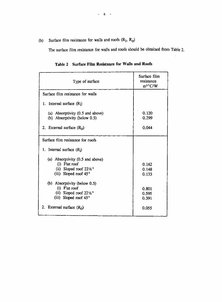
(b) Surface film resistance for walls and roofs (Rj, R0)
The surface film resistance for walls and roofs should be obtained from Table 2.
Table 2 Surface Film Resistance for Walls and Roofs
Type of surfaceSurface filmresistance
m2°C/W
Surface film resistance for walls
1. Internal surface (Rj)
(a) Absorptivity (0.5 and above)(b) Absorptivity (below 0.5)
2, External surface
0.1200.299
0.044
Surface film resistance for roofs
1. Internal surface (Rj)
(a) Absorptivity (0.5 and above)(i) Flat roof
(ii) Sloped roof 22%°(iii) Sloped roof 45°
(b) Absorptivity (below 0.5)(i) Flat roof
(ii) Sloped roof 22%°(iii) Sloped roof 45°
2. External surface (R0)
0.1620.1480.133
0.8010.5950.391
0.055

(c) Air space resistance for walls and (Ra)
The air space resistance for walls and be 3.
Table 3 Air for and
Type of air space
Air space resistancefor walls
Vertical air space (heat flowshorizontally)
(a) Absorptivity (0.5 andabove)
(b) Absorptivity (below 0.5)
Air space resistancefor roofs
Horizontal or sloping air space(heat flows downward)
(a) Absorptivity (0.5 andabove)
(i) horizontal air space(ii) sloped air space 11lh.°
(iii) sloped air space 45°
(b) Absorptivity (below 0.5)
(i) horizontal air space(ii) sloped air space 22V4°
(iii) sloped air space 45°
Air space resistance (Ra) m2°C/W
5mm
0.110
0.250
0.1100.1100.110
0.2500.2500.250
10mm
0.123
0.359
0.1230.1230.123
0.3570.3570.357
20mm
0.148
0.578
0.1480.1480.148
0.5720.5710.570
50mm
0.153
0.589
0.1580.1540.152
0.8910.7680.644
75mm
0.156
0.597
0.1660.1600.155
1.1570.9310.706
100mm
0.160
0.606
0.1740.1650.158
1.4231.0950.768
Absorptivity (a)
73 Energy simulation studies for Hong Kong have shown that the externalsurface and colour of walls and roofs, and therefore their absorptivity, have a significanteffect on chiller energy used. This should be included in the heat gain calculation as amultiplication constant to the equivalent temperature difference. The absorptivity forwall and roof surfaces should be obtained from Table 4.

10
Table 4 Absorptivity for wall and roof surfaces
Material
Black glass
Black concrete
Stafford blue brick
Red brick
Bituminous felt
Blue grey slate
Roofing, green
Brown concrete
Asphalt pavement,weathered
'Wood, smooth
Uncoloured concrete
White marble
White mosaic tiles
Light buff brick
•Built-up roof, white
Bituminous felt,aluminized
Gravel
White on galvanized iron
White glazed brick
Polished aluminiumreflector sheet
Aluminized mylar film
\ Tinned surface
Absorptivitya
1.0
0.91
0.89
0.88
0.88
0.87
0.86
0.85
0.82
0.78
0.65
0.58
0.58.
0.55
0.50
0.40
0.29
0.26
0.25
0.12
0.10
0.05
Paint
Optical flat black paint
Flat black paint
Black lacquer
Dark grey paint
Dark blue lacquer
Black oil paint
Dark olive drab paint
Azure blue or dark greenlacquer
Dark brown paint
Dark blue-grey paint
Medium brown paint
Medium light brown paint
Brown or green lacquer
Medium rust paint
Light grey oil paint
Red oil paint
Medium dull green paint
Medium orange paint
Medium yellow paint
Medium blue paint
Medium kelly green paint
Lighy*reen paint
Aluminium paint
White semi-gloss paint
White gloss paint
Silver paint
White lacquer
Laboratory vapourdeposited coatiiigs
Absorptivitya
0.98
0.95
0.92
0.91
0.91
0.90
0.89
0.88
0.88
0.88
0.84
0.80
0.79
0.78
0.75
0.74
0.59
0.58
0.57
0.51
0.51
0.47
0.40
0.30
0.25
0.25
0.21
0.02
Note: - _ • ' . . . - . ; , . .
Absorptivity for other materials or surfaces should be subject to theaottp&pre of the Building Authority and the source of the informationfrom wMcfe the ajb^rptivity values are obtained should be submitted forhis conslderatioiL

11
Equivalent temperature difference for walk
7-4 Energy simulation studies for Hong Kong have indicated that thermal mass
affects the total heat flow through walls sufficiently to warrant its inclusion in the
formulation of an OTTV. The equivalent temperature difference for walls should take
into account the wall mass, density and orientation. Heavyweight construction gives a
better performance than lightweight construction because it resists the passage of heat.
The equivalent temperature difference for walls should be obtained from Table 5.
Table 5 Equivalent Temperature Difference for Walls
Orientation
N
NNE
NE
ENE
E
ESE
SE
SSE
S
SSW
SW
WSW
W
WNW
NW
NNW
Density of wall construction
less than
22kg/m2
3.70
4.65
5.60
6.55
7.50
7.05
6.60
6.15
5.70
6.15
6.60
6.55
6.50
5.80
5.10
4.40
23-199
kg/m2
3.38
4.21
5.03
5.86
6.68
6.26
5.85
5.43
5.01
5.42
5.82
5.81
5.79
5.19
4.59
3.98
200-379
kg/m2
2.72
3.30
3.86
4.44
5.01
4.65
4.30
3.95
3.60
3.92
4.23
4.29
4.35
3.94
3.54
3.13
380-569
kg/m2
2.05
2.36
2.67
2.98
3.28
3.00
2.71
2.43
2.15
2.37
2.59
2.73
2.86
2.66
2.45
2.25
570 kg/m2
or greater
1.70
1.88
2.05
2.23
2.40
2.15
1.90
1.65
1.40
1.58
1.75
1.93
2.10
2.00
1.90
1.80

12
Shading coefficient of fenestration (SC)
7.5 The shading coefficient of fenestration is the ratio of the solar heat gainthrough a particular type of glass under a specific set of conditions to the solar heat gainthrough double strength sheet clear glass under the same conditions. Allowances forHong Kong's latitude and solar effects have been taken into account in the solar factorand therefore the shading coefficient of glass published by glass manufacturers in HongKong or overseas can be used without modification provided that" the calculations havebeen based on a normal angle of incidence.
External shading multiplier (ESM)
7.6 Shading of windows is of paramount importance in reducing solar heat gainto the building. This shading can be provided by projections over the window, at theside of the window, or a combination of both. For the purpose of simplicity in OTTVcalculations this shading effect is taken into account as an external shading multiplierwhich should be assessed as follows :
(a) Overhang projections to windows
The external shading multiplier for overhang projections to windows should beobtained from Table 6 according to the overhang projection factor (OFF) and theorientation of the window. The OFF should be calculated as follows :
OVERHANG PROJECTION
WINDOW
/ A B
OFF «B

13
Table 6 External Shading Multiplier for Overhang ProjectionsWindows
OFF
0.00
0.05
0.10
0.15
0.20
0.25
0.30
0.35
0.40
0.45
0.50
0.55
0.60
0.65
0.70
0.75
0.80
0.85
0.90
0.95
1.00
ESM
N
1.000
0.975
0.951
0.928
0.905
0.883
0.861
0.840
0.820
0.800
0.781
0.762
0.744
0.726
0.710
0.693
0.678
0.663
0.648
0.634
0.621
NE/NW
1.000
0.969
0.939
0.909
0.880
0.853
0.826
0.800
0.774
0.750
0.726
0.704
0.682
0.661
0.641
0.621
0.603
0.585
0.568
0.552
0.537
S/E/W
1.000
0.962
0.926
0.890
0.856
0.823
0.790
0.759
0.729
0.700
0.672
0.645
0.620
0.595
0.572
0.549
0.528
0.507
0.488
0.470
0.453
SE/SW
1.000
0.962
0.926
0.890
0.856
0.823
0.790
0.759
0.729
0.700
0.672
0.645
0.620
0.595
0.572
0.549
0.528
0.507
0.488
0.470
0.453
Notes :
(i) Should the OFF value fall in between Increments,adopt the multiplier related to the next largerOFF value.
(ii) OFF values above 1.0 are considered to producetoo great an error in estimation.
(iii) ESM for South, East and West orientations arecombined since the figures are very similar.

14
(b) Sidefin projections to windows
The external shading multiplier for sidefin projections to windows should beobtained from Table 7 according to the sidefin projection factor (SPF) and theorientation of the window. The SPF should be calculated as follows :
WINDOW
SIDEFINPROJECTION
-*- -h
SPF=g
Table 7 External Shading Multiplier for SidefinProjections to Windows
SPF
0.00
0.05
0.10
0.15
0.20
0.25
0.30
0.35
ESM
N
1.000
0.955
0.911
0.869
0.828
0.789
0.751
0.714
NE
1.000
0.964
0.929
0.896
0.863
0.832
0.801
0.772
E
1.000
0.974
0.948
0.923
0.898
0.875
0.852
0.829
SE
1.000
0.968
0.937
0.906
0.877
0.848
0.821
0.794
S
1.000
0.962
0.925
0.890
0.855
0.822
0.790
0.759
SW
1.000
0.968
0.936
0.906
0.876
0.848
0.820
0.793
W
1.000
0.968
0.947
0.922
0.897
0.873
0.850
0.828
NW
1.000
0.964
0.929
0.895
0.863
0.831
0.800
0.771
(Cont'd)

15
Table 7 forProjections to
SPF
0.40
0.45
0.50
0.55
0.60
0.65
0.70
0.75
0.80
0.85
0.90
0.95
1.00
1.05
1.10
1.15
1.20
1.25
1.30
1.35
1.40
1.45
1.50
N
0.679
0.645
0.613
0.582
0.553
0.525
0.499
0.473
0.450
0.428
0.407
0.388
0.370
0.354
0.339
0.325
0.313
0.302
0.293
0.286
0.279
0.274
0.271
ESM
NE
0.743
0.716
0.690
0.664
0.640
0.617
0.595
0.574
0.554
0.535
0.517
0.500
0.484
0.470
0.456
0.444
0.432
0.422
0.412
0.404
0.396
0.390
0.385
E
0.807
0.786
0.766
0.746
0.727
0.709
0.691
0.674
0.658
0.642
0.627
0.613
0.599
0.586
0.574
0.562
0.551
0.541
0.531
0.522
0.514
0.506
0.499
SE
0.768
0.743
0.719
0.696
0.674
0.653
0.632
0.613
0.594
0.577
0.560
0.544
0.529
0.515
0.502
0.490
0.478
0.468
0.458
0.450
0.442
0.435
0.429
S
0.729
0.700
0.673
0.646
0.621
0.596
0.573
0.551
0.531
0.511
0.493
0.475
0.459
0.444
0.430
0.417
0.406
0.395
0.386
0.377
0.370
0.364
0.359
SW
0.767
0.743
0.719
0.696
0.674
0.653
0.633
0.613
0.595
0.578
0.561
0.546
0.531
0.518
0.505
0.494
0.483
0.473
0.464
0.456
0.449
0.443
0.438
W
0.806
0.785
0.765
0.746
0.727
0.709
0.692
0.675
0.660
0.645
0.630
0.617
0.604
0.592
0.581
0.570
0.560
0.551
0.543
0.535
0.528
0.522
0.517
NW
0.742
0.715
0.689
0.664
0.640
0.617
0.595
0.574
0.555
0.536
0.519
0.502
0.487
0.473
0.460
0.448
0.437
0.427
0.418
0.410
0.404
0.398
0.394
Notes :
(i) SPF values above 1.5 are considered to produce toogreat an error in estimation.
(ii) Should the SPF value fall in between increments, adoptthe multiplier related to the next larger SPF value.

16
(c) Combination of overhang and sidefin projections
For windows with both overhang and sidefin projections each external
shading multiplier should be calculated separately as described in (a)
and (b) and the smaller of the two values obtained should be used as the
external shading multiplier in the OTTV calculations.
Solar factor (SF)
7.7 The solar factor for vertical surfaces at various orientations and
that for horizontal surfaces should be obtained from Table 8. The solar factors
have been calculated for the Hong Kong climate. Any sloping or angled wall or
roof can be resolved into vertical and horizontal components. The vertical
components of the sloping or angled wall or roof can be treated as a vertical
surface with a solar factor at that respective orientation; whereas the horizontal
component can be treated as a horizontal surface.
Table 8 Solar Factor
orientation
SF for verticalsurface
orientation
SF for verticalsurface
SF forhorizontalsurface
N
104
NNE
121
NE
138
ENE
153
E
168
ESE
183
SE
197
SSE
194
S
191
SSW
197
sw202
WSW
189
W
175
WNW
157
NW
138
NNW
121
264
Equivalent temperature difference for roofs (TDgQr)
7.8 The equivalent temperature difference for roofs should take intoaccount the roof mass and density and should be obtained from Table 9.
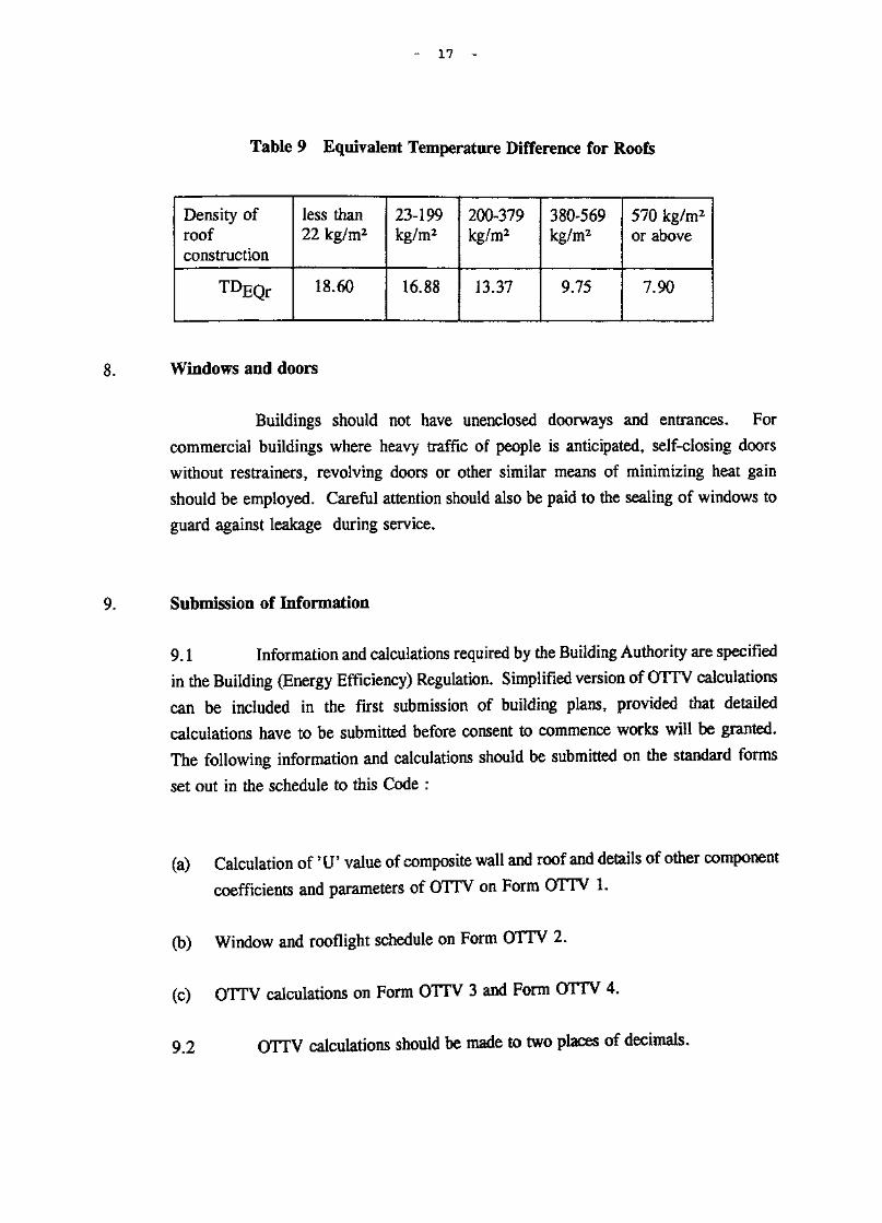
17
Table 9 Equivalent Temperature Difference for Roofs
Density ofroofconstruction
TDEQr
less than22 kg/m2
18.60
23-199kg/m2
16.88
200-379kg/m2
13.37
380-569kg/m2
9.75
570 kg/m2
or above
7.90
Windows and doors
Buildings should not have unenclosed doorways and entrances. For
commercial buildings where heavy traffic of people is anticipated, self-closing doors
without restrainers, revolving doors or other similar means of minimizing heat gain
should be employed. Careful attention should also be paid to the sealing of windows to
guard against leakage during service.
Submission of Information
9.1 Information and calculations required by the Building Authority are specified
in the Building (Energy Efficiency) Regulation. Simplified version of OTTV calculations
can be included in the first submission of building plans, provided that detailed
calculations have to be submitted before consent to commence works will be granted.
The following information and calculations should be submitted on the standard forms
set out in the schedule to this Code :
(a) Calculation of 'IT value of composite wall and roof and details of other component
coefficients and parameters of OTTV on Form OTTV 1.
(b) Window and rooflight schedule on Form OTTV 2.
(c) OTTV calculations on Form OTTV 3 and Form OTTV 4.
9.2 OTTV calculations should be made to two places of decimals.

of S •ta.nclaxrcl I?1 oar mas
OTTV X
Foirm OTTV 2
OTTV 3
OTTV 4

Building (Energy Efficiency) RegulationForm OTTV 1
Calculation of 'IT Value of Composite Wall/Roofand Details of Other Values
Sheet No. A BD Ref 2/ / /Building address
Physical data of Opaque *Wall/RoofFacade Orientation facing ______ Solar Factor (SF) is
*Wall/Roof Code Mo.
Location of Wall/Roof
External Finish Material
Conductivity W/m°CDensity kg/mj
Thickness m
Absorptivity (a)
Intermediate component
Conductivity W/m°CDensity kg/mj
Thickness m
Intermediate component
Conductivity W/m°C
Density kg/mj
Thickness m
Intermediate component
Conductivity W/m°CDensity kg/mj
Thickness m
Intermediate component
Conductivity W/ro°C
Density kg/mj
Thickness m
Internal Finish Material
Conductivity ¥/M0C
Density kg/nr5
Thickness mAbsorptivity a
^U1 value of composite*Wall/Roof
Area of *Wall/Roof m2
Density of composite*Wall/Roof kg/»a
Equivalent temperaturedifference ^TDE(P
*WI/RI *VR2 *W3/R3 *W4/R4
*pelete as appropriateFirst issue April 199J

Building (Energy Efficiency) Regulation
findow/Rooflight Schedule
Mo. BBuilding address
Physical data on *window/roofligfat
Facade Orientation facing
BD Ref 2/
Solar Factor (SF) is
Window/Roof light Code No.
Location of * Window/Roof light
Glazing type
Thickness n
Shading Coefficient (SC)
Type of shading device
External ShadingMultiplier (ESM)
Area of glazing a2
fcFj/RLj *F2/RL2 *F3/RL3 *F4/RL4
Physical data on ^window/rootlight
Facade Orientation facing Solar Factor is
Window/Rooflight Code No.
Location of ^Window/Roof light
Glazing type
Thickness m
Shading Coefficient (SC)
fype of shading device
External ShadingMultiplier (ESM)
Area of glazing m2
*Fl/iLl *VRL2 *F3/RL3 *F4/RL4
* Delete as appropriate
First isstie April 1995

Building (Energy Efficiency) Regulation
Calculation of OTTV of Individual in Building Envelope
Sheet No, C
Building address
Facade Orientation facing
BD Ref II i I
Opaque *Walls/Roofs
CodeNo.
Description
Subtotals
*V*r U a ™EQ
(A) Heat Gain
Stiff!
(C)
Fenestration
CodeNo.
Description
Subtotals
*Af¥/Afr SC ESM SF
(B) Heat Gain
Sura
(D)
Gross Heat Gain (C + D)
Gross Area (A + B)
C + D
A + BOTTV
*.Delete as appropriate
First issue April 1995

Building (Energy Efficiency) Regulation_____^^
of OTTV of Building Envelope
Sheet No. D
Building address
BD Ref. 2/ / _ /
Total Envelope Heat Gain (* Tower/Podium)
r ~ ™" "~™ "~ "•" ""•""'Facade
Orientation1
a*
b.
c .
d.
e.
f.
Subtotal
Roof
: a*
b.
Subtotal
Gross Areafrom
Form 3
(E)
(F)
Gross HeatGain fromForm OTTV3
(G)
(H)
Tower/Podiu« Halls OTTV =
* Tower/Podiu« Roofs OTTV = —
Towdt/Podium OTTf
G
rH
FG + H
W/ra*
W/ffi2
* Delete as appropriate'
First issue April 1995

AppondLxx A
sa.m;pXe; of OTTV calculi <a t xon Iioir
a typxcail commeircxcil t>uilcixngr

Roof.
Offices
external opaquerail finish on,6/F - 26/F is>lack glass
Offices
RefugeFloor
Offices
U
external opaquerail finish on>/F - 14/F is
mosaic tiles
Offices
Podium
Carpark
Carpark
Shops
Shops
Shops
I I
Roof
26/F
16/F
15/F
14/F
5/F
4/F
3/F
2/F
1/F
G/F
1 Basement
East Elevation

S 1 (stairs)
3*0 shops
(stairs)Basement
/
5.0, 6 . 0 . 6 . 0 , 6 . 0 . 6 . 0 , 6 . 0 , 5 . 0 ./ i f I/ I/ I/ I/ i / ! /
v * v • v » w _ %r * vc _
f f-f f
3,0
shops
3.0
{Toilet)
(Duct}
LW
D
(Lightwell)
Lift
Lift ";; Lobby
•n • n/ \
o
VD
G/F
/ / / / . 7\

3 — o • a TJ o—• n—• TJ c
shops
oQ
<\l
ramp
/\
Lift
Lift Lobb
*-* *•3 9.3
CLJ£2 EL _n a l/F
J y U U ' U ' "U O C
3 Carpark IF^
, 1 sI
Ii
1 l
3 i
3 f&
i f
/\
rampup
JK"
t>irampup
/K
•a
i n f t J
t=c
^ c
_ LWT
Lift ;
****** - • •- — L- - i"--"' -"D fift Lobby]
c
S I . ; , p 2/F

ar - a cr — • - TJ
carpark
TT n
3 .n n n n . n 3/F
S podium
O «— — — «f»<|--* — — TT*" r • 'U P — *IJ Sta «==c
i R» — — Ii "ft |
I | D Liift Lobby]D ^>MIM~ •*
. . • • . IiIa cs „,.
1, I " I ,
s
iI1t
[4/P

6.3 6.0 6.3
t f—1 fjo m ipf
office
3
T
D
LW 0.1
T
s
^c§70
Lift '1
Lift Lobby | ]
3
1 ' f , s i
c
f
en
IC\
vO
O
vO
5/F - 14/P
refugefloor
LW , 6.6
Lift
Lift Lobby|
1 15/F

0.1
3.0 2.3
j ti Uoffice
I
3IstT
D
P— s|*|
L,
s
f
Lift ^
Lift Lobby;
3
1 1i s .C
J™ 16/P - 26/F
Roof

Construction of
white semi gloss paint
10 mm gypsum plaster
100 mm concrete wall
10 mm.cement/sand render
5 mm mosaic tiles
PANEL WALLSGROUND - 15TH FLOOR
2 nun steel facing panel
50 mm air gap
75 mm mineral wool insulation
8 mm black glass
white semi gloss paint
CURTAIN WALL16TH FLOOR - 26TH FLOOR
\7\7\25 mm concrete tiles
20 mm asphalt
50 mm cement/sand screed
50 mm expanded polystyrene
150' mm concrete
10 mm gypsum plaster
white semi gloss paint
ROOF

100
500
1600
1000
700
TYPICAL SECTION
5TH FLOOR - 26TH FLOOR

Gross Wall Calculations
Storey heights :Ground and First Floors 4.0 m2nd & 3rd floors 3.5 m4th to 26th floors 3.2 mAll columns 600 x 600 mm All 600 x 600 mm
East Elevation
P G/F1/F
11.0 x 4.0 * 2 + 29 x 4.040 x 4.0 + 23 x 4 x 0.5
138.00 ra2206.00 m* 344.00
T 5/F-14/F 23.0 x 3.2 x 1016/F-26/F 23.0 x 3.2 x 11
736.00 ra«809.60 m* 1,545.60
5/F-14/F 6.3 x 3.2 x 1016-26/F 6.3 x 3.2 x 11
201.60 m*221.76 m* 423.36
North Elevation
P G/F1/F
40.0 x 4.040.0 x 4.0
160.00160.00 320.00
T 5-14/F16-26/F
18.6 x 3.2 x 10(18.6 + 9) x 3.2 x 11
595.20 IB*971.52 nt* 1,566.72
West Elevation
P G/F1/F
40 x 4.040 x 4.0 + 23 x 4 x 0.5
160.00 •>206.00 ra2 366.00 m*
T 5/F-14/F 29.3 x 3.2 x 1016/F-26/F 29.3 x 3.2 x 11
937.60 ta*1,031.36 m* 1,968.96 »*
South Elevation
P G/F Nil = -1/F 40 x 4.0 + (5.4x23.35-5.4x4.0) = 264.49 ra2 264.49 m2
T 5/F-14/F 18.6 x 3.2 x 1016/F-26/F (18.6 + 9) x 3.2 x 11
595.20 HI*971.52 ra* 1,566.72 m2

A10
Window Schedule
Building Address Typical Commercial Building
Orientationof Facade
East
North
West
South
Floor
G/F
1/F
2-4/F
5-14/F
5-14/F
15/F
16-26/F
16-26/F
G/F
1/F
2-4/F
5-14/F
15/F
16-26/F
G/F
1/F
2-4/F
5-14/F
15/F
16-26/F
G/F
1/F
2-4/F
5-14/F
15/F
16-26/F
16-26/F
ClassThickness
m
0.012
0.012
Nil
0.008
0.008
Nil
0.008
0.008
0.012
0.012
Nil
0.008
Nil
0.008
0.012
0.012
Nil
0.008
Nil
0.008
Nil
0.012
Nil
0.008
Nil
0.006
0.008
Type
plain
plain
Nil
tinted
tinted
tinted
tinted
tinted
plain
plain
Nil
tinted
Nil
tinted
plain
plain
Nil
tinted
Nil
tinted
Nil
plain
Nil
tinted
Nil
reflect-ive
tinted
Sizes and no. /floorm
(5.4 x 4 + 4.1) 3.4
(4.1x2 + 5.4x5) 3.4
(4.1+5.7+5.4x2) 1.6
2.7 x 1.6
-
(4.1+5.7+1.4+5.4) 1.6+3.9x0.8
2.7 x 1.6
(4.1+5.4x5+1.7+2.3)3.4
(4.1x2+5.4x5) 3.4
-
(2.3+3.0+5.4x2) 1.6
-
(2.3+3.0+5.4x2) 1.6
(4.1+5.4+2.7) 3.4
(4.1+5.4+2.7) 3.4
-
(5.4x3+4.1) 1.6
-
(5.4x3+4.1) 1.6
-
(4.1x2+2.7+2.6+5.4x3)3.4
-
(5.4x3) 1.6
-
(5.4x3) 1.6
(3.0 + 2.3) 1.6
Total areaper floor
mz
87.38
119.68
-
32.96
4.32
-
29.68
4.32
119.34
119.68
-
25.76
-
25.76
41.48
41.48
-
32.48
-
32.48
-
100.98
-
25.92
-
25.92
8.48

All
East Elevation (Tover) Gross Wall Area 1,545.60 + 423.36 =
Wall composite areas
1,968.96
Beams and Column Areas
5/F - 14/F [0.6 (11.0+5.7+6.3)+(0.6x2.6x4)] 10 = 200.40 m*
15/F Nil
16/F - 26/F [0.6 (11.0+5.4+6.6)+(0.6x2.6x4)3 11 = 220.44 m* 420.84 ra*
Glazing Areas in 100 mm panel/curtain vail from Window Schedule
5/F - 14/F 32.96 x 10 = 329.60 m*
15/F Nil
16/F - 26/F 29.68 x 11 = 326.48 m* 656.08
Glazing Area in 300 mm Structural Walls from Window Schedule
5/F - 14/F 4.32 x 10 = 43.20 m*
15/F 4.32 x 11 = 47.52 •> 90.72 m*
100 mm Panel/Curtain Wall Areas
5/F - 14/F 736.00 - (200.40 + 329.60)
15/F Nil
16/F - 26/F 809.60 - (220.44 + 326.48)
300 mm Structural Walls to Lift & Lift Lobby
5/F - 14/F 0.3 x 3.2 x 3 x 10
16/F - 26/F 0.3 x 3.2 x 3 x 11
300 mm Panel Walls to Lift & Lift Lobby
5/F - 14/F 201.60 - (43.20 + 28.80)
16/F - 26/F 221.76 - (47.52 + 31.68)
Lift shaft vails without gypsum plaster
5/F - 14/F 2.7 x 3.2 x 10
16/F - 26/F 2.7 x 3.2 x 11
Fenestration between 5/F - 14/F
Total Glazing in 100 mm panel walls
(4.1 + 5.7) 1.6 x 10
206.00
262.68 m* 468.68 m*
28.80 m*
31.68 at* 60.48 in*
129.60
142.56 272.16 m*
86.40
95.04 181.44 m*
329.60
156.80 unshaded
172.80 shaded
Fenestration between 16/F - 26/F
Total Glazing in curtain wall
[(4.1+5.7)1.6+(3.9x0.8)] 11
326.48
206.80 unshaded
119.68 shaded

A12
'U' value of composite vail of columns and beams :-G/F, 1/F, 5/F-14/F
Wi for beam and column
external surface film
5 mm white mosaic tiles
10 mm cement/sand render
600 mm concrete beam &column
10 mm gypsum plaster
Internal surface film(absorptivity below 0.5)
Totals
Ro = 0.044
0.005= 0.003
1.5
0.01= 0.014
0.72
0.60- o 278
2.16
0.01= 0.026
0.38
Ri = 0.299
0.664
Weight
0.005 x 2500 = 12.50
0.01 x 1860 = 18.60
0.60 x 2400 = 1440.00
0.01 x 1120 = 11.20
1482.30 kg/mz
0.664= 1.51 W/m*°C
(for west podium wall withouttiles or render %U* value is1.55 W/n*°C}
'U' value of composite wall panels :-G/F, 1/F, 5/F-14/F
«3 for wall panel
external surface film
5 mm white mosaic tiles
10 mm cement/sand render
100 mm concrete panel
10 mm gypsum plaster
Internal surface film
Totals
Ro = 0.044
= 0.003
= 0.014
0.1= 0.046
2.16
= 0.026
Ri - 0.299
0.432
Weight
0.005 x 2500 = 12.50
0.01 x 1860 = 18.60
0.10 x 2400 = 240.00
0.01 x 1120 = 11.20
282.30 kg/m*
U¥ = - 2.320.432
(for west podium wall withouttiles and render *U' value is2.41 W/m*°C)
A13
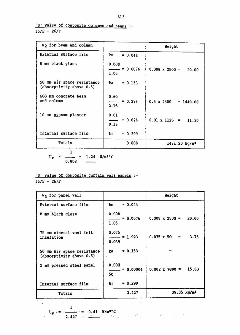
'U' value of composite columns and beams :-16/F - 26/F
¥2 for beam and column
External surface film
8 mm black glass
50 mm Air space resistance(absorptivity above 0.5)
600 mm concrete beamand column
10 mm gypsum plaster
Internal surface film
Totals
Ro = 0.044
0.008= 0.0076
1.05
Ra = 0.153
0.60= 0.278
2.16
0.01= 0.026
0.38
Ri = 0.299
0.808
Weight
0.008 x = 20.00
0.6 x » 1440.00
0.01 x 1120 = 11.20
1471.20
Uw = = 1.24 W/m*°C0.808
'U' value of composite curtain vail panels :-
16/F - 26/F
W4 for panel wall
External surface film
8 mm black glass
75 mm mineral wool feltinsulation
50 mm Air space resistance(absorptivity above 0.5}
2 mm pressed steel panel
Internal surface film
Totals
Ro = 0.044
0.008= 0.0076
1.05
0.075— = 1.923
0.039
Ra =0.153
0.002« 0.00004
50
Ri * 0.299
2.427
Weight
0.008 x 2500 = 20.00
0.075 x 50 - 3.75
—
0,002 x 7800 = 15.60
39.35 kg/m*
- 0.41 W/m*°C2.427

A14
'U' value of structural walls :-G/F, 1/F, 5/F-14/F
Ws for wall panel
external surface film
5 mm white mosaic tiles
10 mm cement/sand render
300 mm concrete wall
10 mm gypsum plaster
Internal surface film(absorptivity below 0.5)
Totals
Ro
0.005
1.5
0.01
0.72
0.30
2.16
0.01
0.38
Ri
= 0.044
= 0.003
= 0.014
= 0.139
=0.026
= 0.299
0.525
Weight
0.005 x 2500 = 12.50
0.01 x 1860 = 18.60
0.30 x 2400 = 720.00
0.01 x 1120 = 11.20
762.3 kg/m2
= 1.9.1 W/m2°C0.525
'U' value of structural walls :•16/F-26/F
(for carpark ramp and walls withouttiles or render %IT value is1.97 W/«a°C)(for lift wall without gypsumplaster %Uf value is 3.13 W/ii2°C)
¥5 for beam and column
external surface film
8 ram black glass
50 mm Air space resistance(absorptivity above 0.5)
300 mm concrete wall
10 mm gypsum plaster
Internal surface film
Totals
Ro
0.008
1.05
Ra
0.30
2.16
0.01
0.38
Ri
= 0.044
= 0.0076
= 0.153
= 0.139
= 0.026
= 0.299
0.669
Weight
o ooft v 9Ron — ?n on
0.3 x 2400 = 720.00
0.01 x 1120 = 11.20
751.20 kg/m2
1 (for lift vail without gypsum~ 1-50 W/<a2°C plaster 'U1 value is 2.16 W/m2°C)
0.669

A15
'U' value of Lift Lobby wall :-
5/F - 14/F
W7 for beam and column
External surface film
5 mm white mosaic tiles
10 mm cement/sand render
*3.0 m concrete lobby vail
Totals
Ro = 0.044
= 0.003
= 0.014
3.00= 1.389
2.16
1.450
Weight
0.005 x = 12.50
0.01 x = 13.60
3.00 x = 7200.00
7231.10
U¥ = a 0.69 i/m2°C1.45
* 3.0 ii length assuredfor simplicity
*Uf value of Lift Lobby vail :-
16/F - 26/F
Ws for beam and column
External surface film
8 mm black glass
50 mm Air space resistance(absorptivity above 0.5}
*3.0 m concrete lobby vail
Totals
Ro = 0.044
= 0.0076
Ra = 0.153
= 1.389
= 1.594
Weight
0.008 x 2500 = 20.00
3.00 x 2400 = 7200.00
7220.00 kg/**
uw = 0.63 W/m*eC1.594

A16
Building (Energy Efficiency) Regulation__ Form OTTV .!_
Calculation of *U' Value of Composite Wall/Roofand Details of Other Values
Sheet No. h iBuilding address Typical Commercial Building
BD Ref 2/
Physical data of Opaque *Wall/Roof
Facade Orientation facing East (Tower) Solar Factor (SF) is 168
*Wal I/Roof Code No.Location of Wall/RoofExternal Finish MaterialConductivity W/m°C
Density kg/m3
Thickness mAbsorptivity (a)Intermediate componentConductivity W/m°C
Density kg/in3
Thickness mIntermediate componentConductivity W/m°CDensity kg/m3
Thickness m
Intermediate component
Conductivity W/m°CDensity kg/m3
Thickness m
Intermediate componentConductivity W/m°CDensity kg/m3
Thickness m
Internal Finish MaterialConductivity W/m°CDensity kg/ra3
Thickness mAbsorptivity a
'U 1 value of composite*iall/RoofArea of *Wall/Roof a*
Density of composite*Wall/Roof kg/it*Eguivalent temperaturedifference (TD«A)
- - — ^
*VRiBeans & Cols5/F-14/F
1.50
25000.005
0.58
cement raider0.72
1860
0.01
r . concrete2.16
2400
0.60
wl
0.381120
0.01
0.30
1.51
200.401482
2.40
*VR2Beams & Cols16/F-26/F
1.05
25000.008
1.00
air gap
0.05
r. concrete2.16
2400
0.60
dte semi glo;on gypsum p!
0.38
1120
0.010.30
1.24
I 220.44
i 1471
: 2.40
*VR3Panel CurtainWalls 5/F-14/F
1.50
25000.005
0.58
cement render0.72
1860
0.01
r. concrete2.16
2400
0.10
is paint
.aster
0.38
1120
0.01
0.30
2.32
206.00
282
5.01
*W4/R4
Panel Curtainfell 16/F-26/F
1.05
2500
0.008
1.00
mineral wool0.03950
0.075
air gap
0.05
white semio*l O^SQ "na i Tit" nn
steel' panel
50
7800
0.0020.30
0.41
262.68
39
6.68
*Delete as appropriateFirst issue April 1995

A17
Building (Energy Efficiency) RegulationForm OTTV 1
Calculation of 'U1 Value of Composite Wall/Roofand Details of Other Values
HA)Sheet No. A _
Building address Typical Commercial BuildingBD Ref 2/ / /
Physical data of Opaque *Wall/Roof
Facade Orientation facing East (Tower) Solar Factor (SF) is 168
*Wall/Roof Code No.
Location of Wall/RoofExternal Finish MaterialConductivity W/m°CDensity kg/m^
Thickness m
Absorptivity (a)
Intermediate component
Conductivity W/m°CDensity kg/in3
Thickness m
Intermediate componentConductivity W/m°CDensity kg/m3
Thickness m
Intermediate component
Conductivity W/m°CDensity kg/m3
Thickness m
Intermediate component
Conductivity W/m°C
Density kg/m3
Thickness mInternal Finish Material
Conductivity W/m°CDensity kg/m^
Thickness m
Absorptivity a4 U ' value of composite*Wall/RoofArea of *Wall/Roof m2
Density of composite*Wall/Roof kg/m*Equivalent temperaturedifference ITDEQJ
*W5/R5
35?F^F fellS
wnrce mosaictiles1.50
2500
0.005
0.58
cement render0.72
1860
0.01
r. concrete2.162400
0.30
white semi gLoen gypsum D!
0.38
1120
0.01
0.30
1.91(3.13}
43.20(86.4)
762(751)
2.40
*VR6
^efcS/F*black glass
1.05
2500
0.008
1.00
air gap
0.05
r . concrete2.162400
0.30
33 paintasterr 0.38
11200.010.30
1.50(2.16)
47.52(95.04)751(740)
2.40
*W7/R?
^P^1white mosaictiles1.50
2500
0.005
0.58
cement render0.72
1860
0.01
r. concrete2.162400
3.00
0.69
28.807231
2.40
*VR8
^y^fp*11
black glass1.0525000.0081.00
air gap
0.05r. concrete
2.1624003.00
0.63
31.687220
2.40
( ) Lift shaft vails without gypsum plaster*Delete as appropriate
First issue April 1995

A18
Building (Energy Efficiency) RegulationForro OTTV 2
Window/Rooflight Schedule
Sheet No. B 1 BD Ref 2/ / /
Building address Typical Commercial Building
Physical data on *vindow/rooflight
Facade Orientation facing East (Tower) Solar Factor (SF) is 168
Window/Roof light Code No*
Location of *Window/Rooflight
Glazing type
Thickness it
Shading Coefficient (SC)
Type of shading device
External ShadingMultiplier (ESM)
Area of glazing m2
*F1/RL1
5/F-14/Fshaded
tinted
0.008
0.70
solidoverhang
0.7
172.80
*VRL2
5/F-14/Funshaded
tinted
0.008
0*70
—
—
156.80
*F3/RL3
16/F-26/Fshaded
tinted
0.008
0.70
aluminiumfoils
0.7
119.68
*F4/RL4
16/F-26/Funshaded
tinted
0.008
0.70
—
—
206.80
Physical data on *windov/roofiight
Facade Orientation facing East (Tower) Solar Factor is 168
iindo /Roof light Code No.
Location of *Window/Rooflight
Glazing type
Thickness m
Shading Coefficient (SC)
Type of shading device
External ShadingMultiplier (ESM)!
Area of glazing m*
*F5/RL5
5/F-14/Funshaded
tinted
0.008
0.70
-
«
43.20
*F6/RL6
16/F-26/Funshaded
tinted
0.008
0.70
-
—
47.52
*F?/RL7 *F8/RL8
* Delete as appropriate
First issue April 1995

119
Building (Energy Efficiency) RegulationForm QTTV 3
Calculation of OTT¥ of Individual Facade in
Sheet No. C BD Ref 2/
Building address Typical Commercial Building
Facade Orientation facing East (Tover)
Opaque ^Walls/Roofs
CodeNo.
Wl
W2
W3
W4
W5
W5A
W6
W6A
W7
W8
Description
Beams & Cols 5/F-14/F
Beams & Cols 16/F-26/F
Panel Curtain Walls5/F-14/F
Panel Curtain Walls16/F-26/F
300 Panel Walls5/F-14/F
300 Lift Walls
300 Panel Walls16/F-26/F
300 Lift Walls
Lift/Lobby wall5/F-14/F
Lift/Lobby wall16/F-26/F
Subtotals
*VAr
200.40
220.44
206.00
262.68
43.20
86.40
47.52
95.04
28.80
31.68
1,222.16
U
1.51
1.24
2.32
0.41
1.91
3.13
1.50
2.16
0.69
0.63
a
0.58
1.00
0.58
1.00
0.58
0.58
1.00
1.00
0.58
1.00
TDEQ
2.40
2.40
5.01
6.68
2.40
2.40
2.40
2.40
2.40
2.40
(A) Heat Gain
Sum
421.22
656.03
1,388.74
719.43
114.86
376.44
171.07
492.69
27.66
47.90
4,416.04 (C)
Fenestration
CodeNo.
FlF2
F3
F4
F5
F6
Description
5/F - 14/F shaded5/F - 14/F unshaded
16/F - 26/F shaded16/F - 26/F unshaded
5/F-14/F unshaded
16/F - 26/F unshadedSubtotals
*Af¥/Afr
172,80156.80
119.68
206.80
43.20
47.52
746.80
SC
0.700.70
0.70
0.70
0.70
0.70
ESM
0.7-
0.7-
-
-
SF
168168
168
168
168
168
(B) Heat Gain
Sum
14,224.9018,439.68
9,852.0624,319.68
5,080.32
5,588.35
77,504.99
Gross Heat Gain (C + D)
Gross Area (A + B)
C + D———_. =A + B
* Delete as appropriate
First issue April 1995
OTTV =
81.921.03
1.968.96f( 41.61 W/m*
(D)

A20
North Elevation (Tover) Gross Wall Area 1,566.72 m2
Wall composite areas
Beams and Column Areas
5/F - 14/F (0.6 x 18.6 + 0.6 x 2.6 x 4) 10 = 174.00 m2
15/F Nil
16/F - 26/F (0.6 x 18.6 + 0.6 x 2.6 x 4) 11 - 191.40 m2 365.40 m*
300 mm Structural Wall to Lift
16/F-26/F 0.3 x 3.2 x 11
300 mm Structural Panel Wallsto Lift
16/F-26/F 9.0 x 3.2 x 11 - 10.56
= 10.56 m2
= 306.24 raa 316.80
Glazing Areas
5/F - 14/F 25.76 x 10
15/F Nil
16/F - 26/F 25.76 x 11
100 nan Staircase Wall
5/F - 14/F 0.1 x 2.6 x 10
16/F - 26/F 0.1 x 2.6 x 11
- 257.60 m»
* 283.36
2.60 HI*
2.86 m2
540.96
5.46 m2
100 mm Wall Panel Areas
5/F - 14/F 595.20 - (174.00 + 257.60 + 2.60} » 161.00 **
15/F Nil =
16/F - 26/F 971.52-U91.40+316.80+283.36+2.86) « 177.10 »* 338.10m2

A21
Building (Energy Efficiency)_____^^
Calculation of 8U S Value of Wall/Roof,and Details of Other Values
Sheet Mo. A BD Ref 2/
Building address Typica. 1 CongercJaJ
Physical data of Opaque *WalI/Roof
Facade Orientation facing North (Tower) Solar Factor (SF) is 104
*Wall/Roof Code No.
Location of Wall/Roof
External Finish MaterialConductivity W/nt°CDensity kg/in3
Thickness m
Absorptivity (a)Intermediate component
Conductivity W/m°C
Density kg/m3
Thickness m
Intermediate component
Conductivity W/m°CDensity kg/m3
Thickness m
Intermediate component
Conductivity W/m°CDensity kg/m3
Thickness m
Intermediate component
Conductivity W/m°C
Density kg/m3
Thickness m
Internal Finish Material
Conductivity W/m°C
Density kg/m3
Thickness m
Absorptivity a
"U f value of composite*Wall/RoofArea of *Wall/Roof m«
Density of composite*Wall/Roof kg/»»Equivalent temperaturedifference ^TDEQ*
*VRIBeams & Oois5/F-14/Fwhite nx)saic
tiles1.50
2500
0.005
0.58
cement render
0.72
1860
0.01
r. concrete2.16
2400
0.60
white
0.38
1120
0.01
0.30
1.51
174.00
1482
1.70
*VR2Beams & Ooii16/F-26/Fblack glass
1.05
2500
0.008
1.00
air gap
0.05
r. concrete2.16
2400
0.60
semi gloss p<gypsum plast<
0.38
1120
0.01
0.30
1.24
191.40
1471
1.70
*VR3'Panel Wails'5/F-14/Fwhite mosaic
tiles1.50
2500
0.005
0.58
cement render
0.72
1860
0.01
r. concrete
2.16
2400
0.10
lint on
ir0.38
1120
0.01
0.302.32
161.00
282
2.72
*W4/R4
Osrtaiyl Wall "oanel1o/F-26/Fblack glass
1.05
2500
0.008
1.00
air gap0.039
50
0.075
air gap
0.05
white semisdoss paint onsteel panel
50
7800
0.002
0.30
0.41
177.10
39
3.38
*Delete as appropriate
First issue April 1995

A22
Building (Energy Efficiency) RegulationForm QTTV 1
Calculation of SU' Value of Composite Wall/Roofand Details of Other Values
Sheet No. A 3Building address Typical Commercial Building
BD Ref 2/ / /
Physical data of Opaque *Wall/Roof
Facade Orientation facing North (Tower) Solar Factor (SF) is 104
* Wai I/Roof Code No.Location of Wall/Roof
External Finish MaterialConductivity W/m°C
' Density kg/m^Thickness mAbsorptivity (a)Intermediate componentConductivity W/m°CDensity kg/m3
Thickness mInterned! ate componentConductivity W/m°CDensity kg/m3
Thickness mIntermediate componentConductivity W/m°CDensity kg/m3
Thickness mIntermediate componentConductivity W/m°CDensity kg/in3
Thickness mInternal Finish MaterialConductivity W/m°CDensity kg/m3
Thickness mAbsorptivity a"IT value of composite*Wall/RoofArea of * Wai I/Roof m2
Density of composite*tfall/Roof kg/in*Equivalent temperaturedifference (TDw))
*VR6300mm Structural
Panel fells16/F-26/Fblade glass
1.05
25000.0081.00
air gap
0.05
r. concrete2.1624000.30
2.16
306.24740
1.70
*W?/R7
1QOmn Staircasewall 5/F-14/Fwhite trasaic
tiles1.50
25000.0050.58
cement render0.72
1860
0.01
r. concrete2.16
24003.00
0.69
2.60
7231
1.70
*VR8lOOnrn Stairwall 16/F-26/Fblack glass
1.0525000.0081.00
air gap
0.05r. concrete
2.1624003.00
0.63
2.867220
1.70
*W8A/R8ABOOnm Structural
Lift tells16/F-26/Fblack glass
1.05
25000.0081.00
air gap
0.05
r. concrete2.1624003.00
0.63
10.567220
1.70
^Delete as appropriateFirst issue April 1995

A23
Building {Energy Efficiency) RegulationForm OTTV 2
Window/Rooflight Schedule
Sheet No* B BB Eef 2/
Building address Typical Commercial Building
Physical data on *windo¥/roofiight
Facade Orientation facing North (Tower) Solar Factor (SF) is 104
Window/Roof light Code No.
Location of *Window/Roof light
Glazing type
Thickness n
Shading Coefficient (SO
Type of shading device
External ShadingMultiplier (ESM)
Area of glazing m2
*F1/RL1
5/F-14/Fshaded
tinted
0.008
0.70
solidoverhang
0.80
257.60
*F9/RL9£3. A
16/F-26/Fshaded
tinted
0.008
0.70
aluminiumfoils
0.80
283.36
*F3/RL3 *F4/RL4
Physical data on *window/rooflight
Facade Orientation facing Solar Factor is
Window/Roof light Code No.
Location of *Window/Rooflight
Glazing type
Thickness m
Shading Coefficient (SC)
Type of shading device
External ShadingMultiplier (ESM)
Area of glazing m2
*F1/RL1 *F2/RL2 *P3/RL3 *F4/Mi4
* Delete as appropriate
First issue April 1995

A24
Building (Energy Efficiency) RegulationForm QTTV 3
Calculation of OTTV of Individual Facade in Building Envelope
Sheet No. C BD Ref 2/
Building address Typical Commercial Building
Facade Orientation facing North (Tover)
Opaque *Walls/Roofs
CodeNo.
Wl
W2
W3
W4
W6
W7
W8
W8A
Description
Beams & Col. 5/F-14/F
Beams & Col. 16/F-26/F
Panels Walls 5/F-14/F
Panels Walls 16/F-26/F
300 mm StructuralPanel 16/F-26/F
100 mm Stair vail5/F-14/F
100 mm Stair wall16/F-26/F
300 mm Lift wall16/F-26/F
Subtotals
*VAr
174.00
191.40
161.00
177.10
306.24
2.60
2.86
10.56
1,025.76
U
1.51
1.24
2.32
0.41
2.16
0.69
0.63
0.63
a
0.58
1.00
0.58
1.00
1.00
0.58
1.00
1.00
TDEQ
1.70
1.70
2.72
3.38
1 . 70
1.70
1 . 70
1.70
(A) Heat Gain
Sum
259.06
403.47
589.27
245.43
1,124.51
1.77
3.06
11.31
2,637.88
Fenestration
(C]
CodeNo.
Fl
F2
Description
5/F - 14/F
16/F - 26/F
Subtotals
*Afw/Afr
257.60
283.36
540.96
SC
0.70
0.70
ESM
0.80
0.80
SF
104
104
(B) Heat Gain
Sum
15,002.62
16,502.89
31,505.51
Gross Heat Gain (C + D) 34,143.39
Gross Area (A + B) 1,566.72
C + DOTTV = 21.79
A + B
* Delete as appropriate
First issue April 1995
(D)
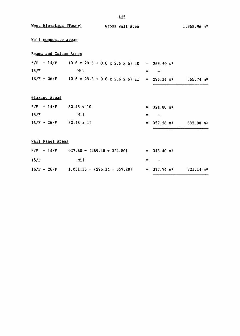
A25
West Elevation (Tower) Gross Wall Area 1,968.96
Wall composite areas
Beams and Column Areas
5/F - 14/F (0.6 x 29.3 + 0.6 x 2.6 x 6) 10 = 269.40 m2
15/F Nil
16/F - 26/F (0.6 x 29.3 + 0.6 x 2.6 x 6} 11 = 296.34 m* 565.74
Glazing Areas
5/F - 14/F 32.48 x 10 = 324.80 m*
15/F Nil
16/F - 26/F 32.48 x 11 = 357.28 m* 682.08
Wall Panel Areas
5/F - 14/F 937.60 - (269.40 + 324.80) = 343.40 m*
15/F Nil
16/F - 26/F 1,031.36 - (296.34 + 357.28) = 377.74 m* 721.14

A26
Building (Energy Efficiency) Regulation_Form OTTV 1 .
Calculation of "II1 Value of Composite Wall/Roofand Details of Other Values
Sheet No. A 3
Building address Typical Commercial Building
BD Ref 2/
Physical data of Opaque *Wall/Roof
Facade Orientation facing West (Tower) Solar Factor (SF) is 175
*Wall/Roof Code No.
Location of Wall/RoofExternal Finish Material
Conductivity W/m°CDensity kg/ra3
Thickness mAbsorptivity (a)Intermediate component
Conductivity W/m°C
Density kg/fit^
Thickness HIIntermediate component
Conductivity i/m°CDensity kg/n3
Thickness IBIntermediate component
Conductivity W/m°CDensity kg/ra3
Thickness mInterned! ate componentConductivity W/m°C
Density kg/m"3"
Thickness mInternal Finish Material
Conductivity W/m°CDensity kg/m^
Thickness mAbsorptivity a
* U f value of composite*Wal I/RoofArea of *Hal I/Roof fi2
Density of composite*Wall/Roof kg/a*Equivalent temperaturedifference (TDPri), , ^y
*v*iBeams & Cols5/F-14/F
white mosaictiles
1.50
2500
0.0050.58
cement render0.72
1860
0.01
r. concrete2.16
2400
0.60
white ;<
0.38
1120
0.01
0.30
1.51
269.40
1482
2.10
*VR2Beams & Cols
16/F-26/Fblack glass
1.05
2500
0.008
1.00
air gap
0.05
r. concrete
2.16
2400
0.60
;emi gloss pa:
sYpsum plaste;
0.38
1120
0.01
0.30
1.24
296.34
1471
2.10
*W3/R3
Panel Ifells5/F-14/Fwhite mosaic
tiles1.50
2500
0.005
0.58
cement render
0.72
1860
0.01
r. concrete2.16
2400
0.10
.nt on
0.38
1120
0.01
0.30
2.32
343.40
282
4.35
*VR4Curtain Wallpanel 16/F-26/F
black glass1.05
2500
0.008
1.00
mineral felt
0.039
50
0.075
air gap
0.05
white semigloss paint onsteel panel
50
7800
0.0020.30
0.41
377.74
39
5.79
*Belete as appropriateFirst issue April 1995

127
Building (Energy Efficiency) RegulationForm 2
Window/Rooflight Schedule
Sheet No, B BD Ref 2/ / /
Building address Typical Commercial Building
Physical data on *window/rooflight
Facade Orientation facing West (Tower) Solar Factor (SF) is 175
Window/Rooflight Code No*
Location of *Window/Rooflight
Glazing type
Thickness m
Shading Coefficient (SC)
Type of shading device
External ShadingMultiplier (ESM)
Area of glazing m2
*F1/RL1
5/F-14/Fshaded
tinted
0.008
0.70
solidoverhang
0*70
324*80
*VRL2
16/F-26/Fshaded
tinted
0.008
0*70
aluminiumfoils
0.70
357.28
*F3/RL3 *F4/RL4
Physical data on *window/rooflight
Facade Orientation facing Solar Factor is
Window/Rooflight Code No.
Location of *Windo¥/Rooflight
Glazing type
Thickness n
Shading Coefficient (SC)
Type of shading device
External ShadingMultiplier (ESM)
Area of glazing »*
*F1/RL1 *F9/RImL &*F3/RL3 *F4/RL4
* Delete as appropriate
First issue April 1995

128
Building (Energy Efficiency) RegulationForm QTTV 3
Calculation of OTTV of Individual Facade in Building Envelope
Sheet No. C BD Ref 2/ / /
Building address Typical Commercial Building
Facade Orientation facing West (Tower)
.Opaque * Wai Is/Roofs
CodeNo.
Wl
W2
W3
W4
Description
Beams & Col. 5/F-14/F
Beams & Col. 16/F-26/F
Panels Walls 5/F-14/F
Curtain Wall Panels16/F-26/F
Subtotals
*Vflr
269.40
296.34
343.40
377.74
1,286.88
U
1.51
1.24
2.32
0.41
a
0.58
1.00
0.58
1.00
TDEQ
2.10
2.10
4.35
5.79
(A) Heat Gain
Sum
495.48
771.67
2,010.04
896.72
4,173.91 CO
Fenestration
CodeNo.
Fl
F2
Description
5/F - 14/F
16/F - 26/F
Subtotals
*Afw/Afr
324.80
357.28
682.08
SC
0.70
0.70
ESM
0.70
0.70
SF
175
175
(B) Heat Gain
Sum
27,851.60
30,636.76
58,488.36 (D)
Gross Heat Gain (C + D) 62,662.27
'Gross Area (A * B) 1,968.96
C + DOTT V =
B31.83
* Delete as appropriate
First issue April 1995

A29
South Elevation (Tower) Gross Wall Area 1,566.72 m*
Wall composite areas
Beam and Column Areas
5/F - 14/F (0.6 x 18.6 + 0.6 x 2.6 x 4) 10 = 174.00 m2
15/F Nil
16/F - 26/F [(0.6 x (18.6+9)+0.6 x 2.6 x 6)] 11 = 285.12 m2 459.12 m2
Glazing Areas
5/F - 14/F 25.92 x 10 = 259.20 m*
15/F Nil
16/F - 26/F 25.92 x 11 = 285.12 m2
16/F - 26/F 8.48 x 11 = 93.28 m2 637.60 m2
100 mm Stair case vail
16/F - 26/F 0.1 x 2.6 x 11 = 2.86 m2 2.86
Wall Panel Areas
5/F - 14/F 595.20 - (174.00 + 259.20) = 162.00 »*
15/F Nil
16/F - 26/F 971.52 - (285.12+285.12+93.28+2.86) = 305.14 m2 467.14 m2
Fenestration between 16/F - 26/F
Total Glazing 285.12 + 93.28 = 378.40 »*
(5.4 x 3) x 1.6 x 11 = 285.12 »* Unshaded
93.28 m2 Shaded
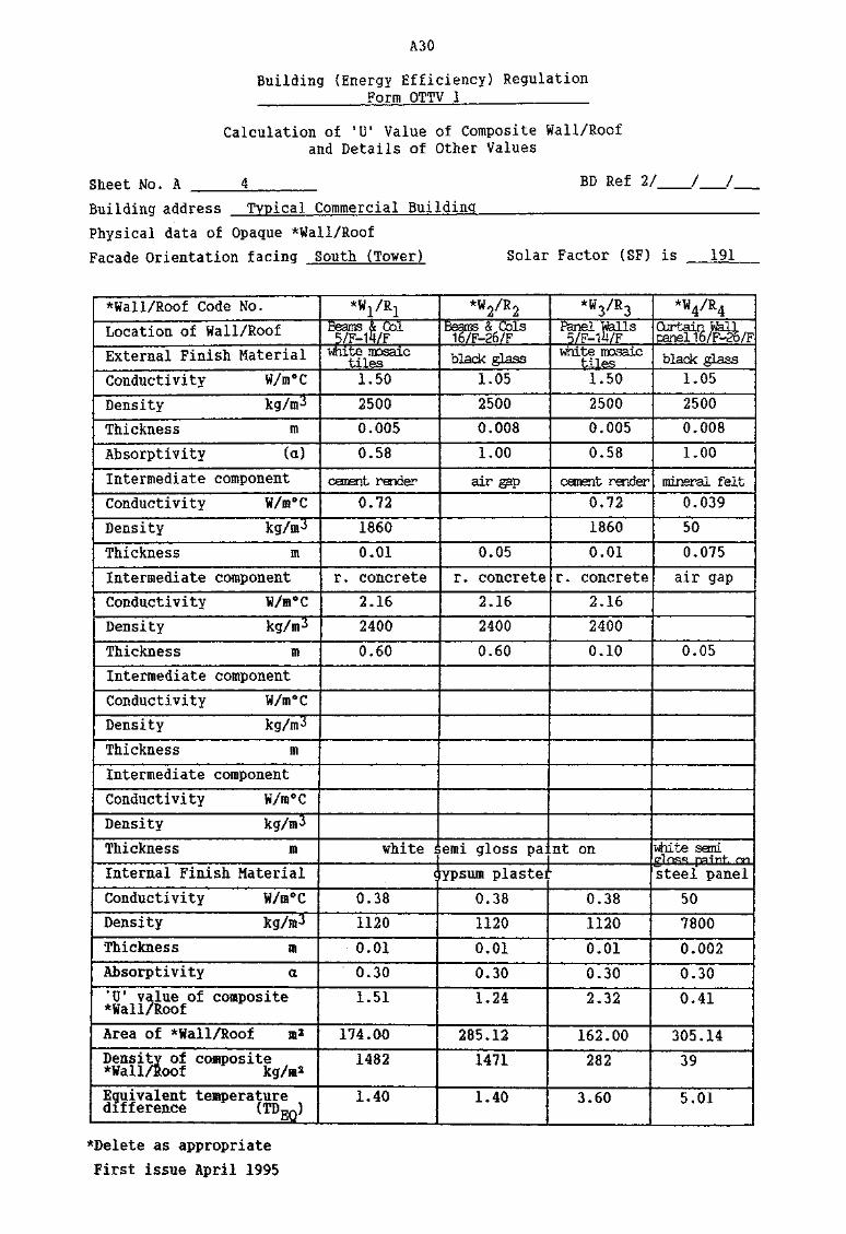
A30
Building (Energy Efficiency) RegulationForm QTTV 1 '
Calculation of S1T Value of Composite Wall/Roofand Details of Other Values
Sheet No. A 4
Building address Typical Commercial Building
BD Ref 2/ / /
Physical data of Opaque *Wall/Roof
Facade Orientation facing South (Tower) Solar Factor (SF) is 191
* Wai I/Roof Code No.Location of Wall/RoofExternal Finish MaterialConductivity W/m°CDensity kg/in3
Thickness m
Absorptivity (a)
Intermediate component
Conductivity W/in°CDensity kg/m3
Thickness m
Intermediate componentConductivity W/m°CDensity kg/it 3
Thickness mIntermediate component
Conductivity W/m°CDensity kg/m3
Thickness m
Intermediate componentConductivity W/m°CDensity kg/m^
Thickness mInternal Finish Material
Conductivity W/m°CDensity kg/m3
Thickness m
Absorptivity a
* U * value of composite*Wall/RoofArea of *Wall/Roof m*Density of composite*Wall/Roof kg/m*Equivalent temperaturedifference (TD™J&U
*wi/RiBeans & Col5/F-14/F
white tBDsaictiles
1.50
25000.005
0.58
cenEnt render0.72
1860
0.01
r . concrete2.16
2400
0.60
white tc
0.38
1120
0.01
0.30
1.51
174.00
1482
1.40
*W2/R2
Beams & Cols16/F-26/Fblack glass
1.05
2500
0.0081.00
air gap
0.05
r. concrete2.16
2400
0.60
emi gloss pa:
[ypsum plastei
0.38
1120
0.01
0.30
1.24
285.121471
1.40
*VR3Panel Walls5/F-14/F
white mosaictiles .1.50
25000.005
0.58
cement render
0.7218600.01
r. concrete2.16
2400
0.10
nt on
0.38
1120
0.01
0.30
2.32
162.00
282
3.60
*W4/R4
black glass1.05
25000.008
1.00
mineral felt0.039
50
0.075
air gap
0.05
white semigloss paint', cmsteel panel
50
7800
0.0020.30
.0.41
305.14
39
5.01
*Delete as appropriate
First issue April 1995

A31
Sheet No. A
Building (Energy Efficiency) RegulationForm QTT¥ 1
Calculation of suf Value of Composite Wall/Roofand Details of Other Values
BD lef 2/ / /Building address Typical Commercial BuildingPhysical data of Opaque *Wall/RoofFacade Orientation facing South (Tower) Solar Factor (SF) is 191
*Wall/Roof Code No.
Location of Wall/RoofExternal Finish MaterialConductivity W/m°C
Density kg/m3
Thickness mAbsorptivity (a)Intermediate componentConductivity W/m°C
Density kg/in3
Thickness in
Intermediate componentConductivity l/m°CDensity kg/m3
Thickness mIntermediate componentConductivity W/m°CDensity kg/m3
Thickness m
Intermediate componentConductivity W/m°C
Density kg/m3
Thickness mInternal Finish Material
Conductivity W/«°CDensity kg/m3
Thickness mAbsorptivity a*U" value of composite*Wall/RoofArea of *Wall/Roof m2
Density of composite*Wall/Roof kg/m*Equivalent temperaturedifference (TIW
*W8/R8
16/F-26/FStaircase vailblack pdass
1.05
2500
0.008
1.00
air gap
0.05
r. concrete2.162400
3.00
0.63
2.867220
1.40
*Delete as appropriateFirst issue April 1995

A32
Building (Energy Efficiency) RegulationForm QTTV 2
Window/Rooflight Schedule
Sheet No. B BD Ref 2/
Building address Typical Commercial Building
Physical data on *¥indov/rooflight
Facade Orientation facing South (Tower) Solar Factor (SF) is 191
Window/Rooflight Code No.
Location of *Window/Roof light
Glazing type
Thickness m
Shading Coefficient (SO
Type of shading device
External ShadingMultiplier (ESM)
Area of glazing m2
*F1/RL1
5/F-14/Funshaded
tinted
0.008
0.70
259.20
*F2/RL2
16/F-26/Funshaded
reflective
0.006
0.40
285.12
*F3/RL3
16/F-26/Fshaded
tinted
0.008
0.70
aluminiumfoils
0.70
93.28
*F4/RL4
Physical data on *window/rooflight
Facade Orientation facing Solar Factor is
lindow/Roof light Code No.
Location of ^Window/Roof light
Glazing type
Thickness in
Shading Coefficient (SO
Type of shading device
External ShadingMultiplier (ESM)
Area of glazing m2
*F1/RL1 *F2/RL2 *F3/RL3 *F4/RL4
* Delete as appropriate
First issue ADril

A33
Building (Energy Efficiency) RegulationForm QTTV 3
Calculation of OTTV of Individual Facade in Building Envelope
Sheet No, C BD Ref 2/
Building address Typical Commercial Building
Facade Orientation facing South (Tower)
Opaque *WalIs/Roofs
CodeNo.
Wl
W2
W3
W4
W8
Description
Beams & Col. 5/F-14/F
Beams & Col. 16/F-26/F
Panels Walls 5/F-14/F
Panels Walls 16/F-26/F
Stair Walls 16/F-26/F
Subtotals
*VAr
174.00
285.12
162.00
305.14
2.86
929.12
U
1.51
1.24
2.32
0.41
0.63
a
0.58
1.00
0.58
1.00
1.00
TDEQ
1.40
1.40
3.60
5.01
1.40
(A) Heat Gain
Sum
213.34
494.97
784.75
626.79
2.52
2,122.37 (C)
Fenestratioa
CodeNo.
Fl
F2
F3
Description
5/F - 14/F unshaded
16/F - 26/F unshaded
16/F - 26/F shaded
Subtotals
*Afy/Afr
259.20
285.12
93.28
637.60
SC
0.70
0.40
0.70
ESM
0.70
SF
191
191
191
(B) Heat Gain
Sum
34,655.04
21,783.17
8,730.08
65,168.29 (D)
Gross Heat Gain (C + D) 67,290.66
Gross Area (A + B) 1,566.72
OTTV =C + D
A + B42.95 W/ffi*
* Delete as appropriate
First issue April 1995
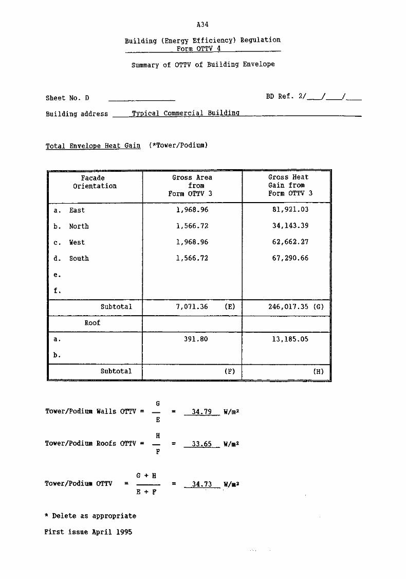
A34
Building (Energy Efficiency) RegulationForm OTTV 4
Summary of OTTV of Building Envelope
Sheet Mo. D
Building address Typical Commercial Building
BD Ref. 2/
Total Envelope Heat Gain (*Tower/Podium)
FacadeOrientation
a. East
b. North
c. West
d . South
e.
f.
Subtotal
Roof
a.
b.
Subtotal
Gross Areafrom
Form OTTV 3
1,968.96
1,566.72
1,968.96
1,566.72
7,071.36 (E)
391.80
(F)
Gross HeatGain fromForm OTTV 3
81,921.03
34,143.39
62,662.27
67,290.66
246,017.35 (G)
13,185.05
(H)
Tower/Podiua Walls OTTV = — = 34*79E
HTower/Podium Roofs OTTV = -— = 33.65
F
Tower/Podiuu OTTVE
34»73
* Delete as appropriate
First issue April 1995

A35
Accountable Roof Areas
Roof
Gross Area = 6.0 x 6.6 + 9.6 x 8.0 •*• 6 x 10.3 + 9.0 x 3.0 +18.6 x 8.0 + (6.3 x 3.0 x 2) = 391.80 m%
Glazed area = 8.4 x 8.0 = 57,20 n2
Beam area = [(15.6 x 2) + (6.0 x 2} + 18.6 + (6.3 x 2) +(5.4 x 9) + 1.4 + (4.1 x 2) -i- (1.7 x 2] +(2,4 x 2 x 0.5) + (3.6 x 0.5)] 0.6 = 84.12 m^
Lift Lobby walls = 0.3 (9+2.7) = 3*51 n2
Panel area = 391.80 - 67.2 - 84.12 - 3.51 = 236.97 n*
15/F
Gross Area = 6.6 x 5.4 + 2.4 x 1.4 = 39,00 ro2
Glazed area = Nil
Beam area , = 0.6. (5.4 x 2) = 6,48 in2
Panel area = ..39.00 - 6.48 = 32.52 Hi2
Podium Roof
Carpark under non-accountable Mil
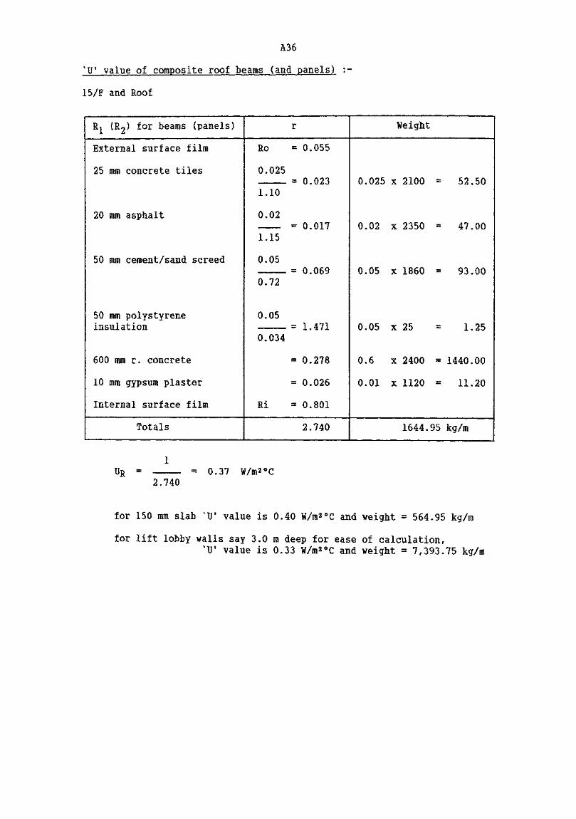
A36
'!)' value of composite roof beams (and panels! :-
15/F and Roof
Rj (R2) for beams (panels)
External surface film
25 mm concrete tiles
20 mm asphalt
50 mm cement/sand screed
50 mm polystyreneinsulation
600 mm r. concrete
10 mm gypsum plaster
Internal surface film
Totals
r
Ro = 0.055
0.025= 0.023
1.10
0.02= 0.017
1.15
0,05= 0 069
0.72
0.05= 1 471
0.034
= 0.278
= 0.026
Ri = 0.801
2.740
Weight
0.025 x 2100 = 52.50
0.02 x 2350 = 47.00
0.05 x 1860 = 93.00
0.05 x 25 = 1.25
0.6 x 2400 = 1440.00
0.01 x 1120 = 11.20
1644.95 kg/m
UR =2.740
= 0.37 W/m2°C
for 150 mm slab %U" value is 0.40 W/m2°C and weight = 564.95 kg/m
for lift lobby walls say 3.0 m deep for ease of calculation,%U' value is 0.33 W/m2°C and weight = 7,393.75 kg/m

A3?
Building (Energy Efficiency) RegulationForm QTTV 1
Calculation of 'IT Value of Composite Wall/Roofand Details of Other Values
Sheet No. A 5
Building address Typical Commercial BuildingBD Ref 2/ / /
Physical data of Opaque *Wall/Roof
Facade Orientation facing Roof (Tower) Solar Factor (SF) is 264
*Wall/Roof Code No.
Location of Wall/Roof
External Finish Material
Conductivity W/m°C
Density kg/nn
Thickness m
Absorptivity (a)
Intermediate component
Conductivity W/m°C
Density kg/m3
Thickness m
Intermediate component
Conductivity W/m°CDensity kg/m^
Thickness m
Intermediate component
Conductivity W/m°CDensity kg/m^
Thickness m
Intermediate component
Conductivity W/m°C
Density kg/m^
Thickness m
Internal Finish Material
Conductivity W/m°CDensity kg/m^
Thickness m
Absorptivity a%U f value of composite*Wall/RoofArea of *Wall/Roof m2
Density of composite*Wall/Roof kg/ra2
Equivalent temperaturedifference ^TDEQ)
*w1/n1Tower- Roof Beamconcrete tiles
1.102100
0.025
0.65
asphalt
1.152350
0.02
cemei
0.72
1860
0.05
6)
0.034
25
0.05
r. concrete
2.16
2400
0.60white semi £
svpsun0.38
1120
0.01
0.30
0.37
84.12
1645
7.90
*VR2Tower Roof Panelsconcrete tiles
1.10
2100
0.025
0.65
asphalt
1.152350
0.02
it/sand screed
0.72
1860
0.05
panded polystyrei
0.034
25
0.05
r. concrete
2.162400
0.15loss paint onBlaster
0.38
1120
0.01
0.30
0.40
236.97
565
9.75
*VR3Tower Eocf Lift fellsconcrete tiles
1.102100
0.025
0.65
asphalt
1.15
23500.02
0.72
1860
0.05
,e0.034
25
0.05
r. concrete
2.16
2400
3.00
0.33
3.51
7394
7.90
*Delete as appropriate
First issue April 1995
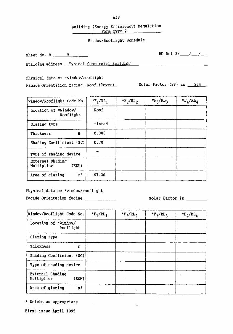
A38
Building (Energy Efficiency) RegulationForm OTTV 2 .
Window/Rooflight Schedule
Sheet No. B BD Ref 2/ / /
Building address Typical Commercial Building
Physical data on *window/rooflight
Facade Orientation facing Roof (Tower) Solar Factor (SF) is 264
Window/Rooflight Code No.
Location of *Window/Roof light
Glazing type
Thickness m
Shading Coefficient (SO
Type of shading device
External ShadingMultiplier (ESM)
Irea of glazing m2
*F1/RL1
Roof
tinted
0.008
0.70
-
67.20
*VRL2 *VRL3 *F4/RL4
Physical data on ^window/rooflight
Facade Orientation facing Solar Factor is
Window/Roof light Code No.
Location of *Window/Roof light
Glazing type
Thickness m
Shading Coefficient (SC)
Type of shading device
External ShadingMultiplier (ESM)
Area of glazing m2
*F1/RL1 *F2/RL2 *VRL3 *F4/RL4
* Delete as appropriate
First issue April 1995

A39
Building (Energy Efficiency) RegulationForm QTTV 3
Calculation of OTTV of Individual Facade in Building Envelope
Sheet No. C
Building address Typical Commercial Building
BD ief 2/
Facade Orientation facing Roof (Tower)
J—J
Opaque *Walls/Roofs
CodeNo.
Rl
R2
R3
Description
Tower Roof Beams
Tower Roof Panels
Tower Roof Stair &Lift Walls
Subtotals
*VAr
84.12
236.97
3.51
324.60
D
0,37
0.40
0.33
a
0.65
0.65
0.65
TDEQ
7.90
9.75
7.90
(A) Heat Gain
Sum
159.82
600.72
5.95
766.49 (C)
Fenestration
CodeNo.
RI
Description
Roof light
Subtotals
*Af¥/Afr
67.20
67.20
SC
0.70
ESM
«•
SF
264
(B) Heat Gain
Sum
12,418.56
12,418,56 ID)
Gross Heat Gain (C + D) 13,185.05
Gross Area (A + B) 391.80
C + DOTTV 33.65
A + B
* Delete as appropriate
First issue April 1995

A40
Building (Energy Efficiency) RegulationForm QTTV 1
Calculation of 'U' Value of Composite Wall/Roofand Details of Other Values
Sheet No. h 5(A) BD Ref 2/ / /
Building address _Tvpical Commercial Building
Physical data of Opaque *Wall/RoofFacade Orientation facing Roof (15/F)... Solar Factor (SF) is 264
*WaI I/Roof Code Mo.Location of Wall/Roof
External Finish Material
Conductivity !/m°C
Density kg?iP~~
Thickness m
Absorptivity (a)Intermediate componentConductivity W/ni0C
Density kg/in3
Thickness mIntermediate component
Conductivity W/m°CDensity kg/m3
Thickness inIntermediate component
Conductivity W/m°CDensity kg/m3
Thickness m
Intermediate component
Conductivity W/m°C
Density kg/m3
Thickness m
Internal Finish Material
Conductivity W/ra°CDensity kg/ra3
Thickness mAbsorptivity a
"U1 value of composite*Hall/RoofArea of *Wall/Roof m*
Density of composite*lall/Roo£ kg/in*
Equivalent temperaturedifference (TDWA)- --- - EQ
*wi/Ri15/F Beams
concrete tiles
1.10
2100
0.025
0.65
asphalt
1.15
2350
0.02
cement/sand sc:
0.72
1860
0.05
expanded polys'
0.034
25
0.05
r. concrete2.16
2400
0.60
white semi gloss pail
0.38
1120
0.010.30
0.37
6.48
1645
7.90
*VR215/F Panels
concrete tiles
1.10
2100
0.025
0.65
asphalt
1.15
2350
0.02
•eed
0.72
1860
0.05
-yrene
0.034
25
0.05
r. concrete
2.16
2400
0.15
it on gypsum plaster
0.381120
0.01
0.30
0.40
32.52
565
9.75
*Delete as appropriateFirst issue ADtil 1995

A41
Building (Energy Efficiency) RegulationForm OTTV 3
Calculation of OTTV of Individual Facade in Building Envelope
Sheet No. C 5(A) BD Ref 2/ / /
Building address Typical Commercial Building
Facade Orientation facing Roof (15/F)
Opaque ^Walls/Roofs
CodeNo.
R3
R4
Description
15/F Beams
15/F Panels
Subtotals
*VAr
6.48
32.52
39.00
U
0.37
0.40
a
0.65
0.65
TDEQ
7.90
9.75
(A) Heat Gain
Sum
12.31
82.44
94.75 (C)
Fenestration
CodeNo.
Description
Subtotals
*Afw/Afr SC ESM SF
(B) Heat Gain
Sun
(D)
Gross Heat Gain (C + D)
Gross Area (A + B)
C •+ D
94.75
39.00
OTTV = 2.43A + B
W/ffi*
* Delete as appropriate
First issue April 1995

A42
East Elevation (Podima) Gross Wall Area 344.00
Wall Composite Areas
Beam and Column Areas
G/F 0.6 x 40.0 + 0.6 (3.4 x 6 + 3.4 x 0.5*) » 37.26 m2
1/F 0.6 x 40.0 + 0.6 (3.4 x 8) » 40.32 ra*
1/F (Ramp) 0.6 x 23.0 + 0.6 (3.4 x 5 x 0.5) = 18.90 m*
2/F - 4/F Nil = - 96.48
Glazing Areas
G/F 87.38 m* = 87.38 m*
1/F 119.68 m* = 119.68 m*
2/F - 4/F Nil = - 207.06
300 mm Retaining Wall
G/F 138.00 - (37.26 + 87.38) » 13.36 m*
300 mm Ramp Wall
1/F 23 x 4 x 0.5 - 18.90 » 27.1 m*
* Only half column considered to contribute

A43
•Building (Energy Efficiency) RegulationForm QTTV 1
Calculation of 'U1 Value of Composite Wall/Roofand Details of Other Values-
Sheet No. A 6
Building address Typical Commercial BuildingBD Ref 2/ / /
Physical data of Opaque *Wall/Roof
Facade Orientation facing East (Podium) Solar Factor (SF) is 168
*Wall/Roof Code No.
Location of Wall/Roof
External Finish Material
Conductivity W/m°C
Density kg/m3
Thickness m
Absorptivity (a)
Intermediate component
Conductivity W/ti°C
Density kg/m3
Thickness m
Intermediate component
Conductivity W/m°C
Density kg/m3
Thickness m
Intermediate component
Conductivity W/m°C
Density kg/m3
Thickness m
Intermediate component
Conductivity tf/m°C
Density kg/m3
Thickness m
Internal Finish Material
Conductivity W/m°C
Density kg/m3
Thickness m
Absorptivity a"U1 value of composite*Wall/RoofArea of *Wal I/Roof m2
Density of composite*Wall/Roof kg/in*Equivalent temperaturedifference ^TDEQ)
*WI/RIBeams & ColsG/F& 1/Fwhite mosai<
1.502500
0.005
0.58cement rei
0.7218600.01
Reinforced <
2.162400
0.60
white semi g'.on gypsum
0.38
1120
0.01
0.30
1.51
96.48
1482
2.40
*VR5Retaining Wall
G/Fi tiles
1.50
2500
0.005
0.58.der
0.7218600.01
oncrete
2.162400
0.30
oss paint
plaster
0.3811200.010.301.91
13.36762
2,40
*W5A/R5A'" Kanp tell
1/F
2.16
2400
0.30
0.65
0.38
1120
0.01
0.30
1.97
27.1
731
2.40
*W /R
*Delete as appropriate
First issue April 1995

A44
Building (Energy Efficiency) RegulationForm OTTV 2
Windo¥/Rooflight Schedule
Sheet No. B BD Ref 2/ / /
Building address Typical Commercial Building
Physical data on *window/rooflight
Facade Orientation facing East (Podium) Solar Factor (SF) is 168
Windov/Roof light Code No.
Location of *Windo¥/Roof light
Glazing type
Thickness ffl
Shading Coefficient (SO
•Type of shading device
External ShadingMultiplier (ESM)
Area of glazing i2
*F1/RL1
G/F&l/Funshaded
plain
0.012
0.90
-
—
207.06
*F2/RL2 *VRL3 *F4/RL4
Physical data on *vindov/rooflight
Facade Orientation facing Solar Factor is
fiindov/Roof light Code No.
Location of *Windo¥/Roof light
Glazing type
Thickness m
Shading Coefficient (SC)
Type of shading device
External ShadingMultiplier (ESM)
Area of glazing i2
*F1/RL1 *F2/RL2 *F3/RL3 *VRL4
* Delete as appropriate
First issue April 1995

A45
Building (Energy Efficiency) RegulationForm QTTV 3
Calculation of OTTV of Individual Facade in Building Envelope
Sheet No. C BD Ref 2/
Building address Typical Commercial Building
Facade Orientation facing East (Podium)
Opaque *WaiIs/Roofs
CodeNo.
Wl
W5
W5
Description
Beams & Col. G/F&l/F
Panels G/F&l/F
Ramp Wall 1/F
Subtotals
*VAr
96.48
13.36
27.10
136.94
U
1.51
1.91
1.97
a
0.58
0.58
0.65
TDEQ
2.40
2.40
2.40
(A) Heat Gain
Sum
202.79
35.52
83.28
321.59 (C)
Fenestration
CodeNo.
Fl
Description
G/F & 1/F
Subtotals
*Afw/Afr
207.06
207.06
SC
0.90
ESM
—
SF
168
(B) Heat Gain
Sum
31,307.47
31,307.47 (D)
Gross Heat Gain (C + D)
Gross Area (A + B)
C + D
31.629.06
344.00
OTTV 91.95 W/ra*A + B
* Delete as appropriate
First issue April 1995
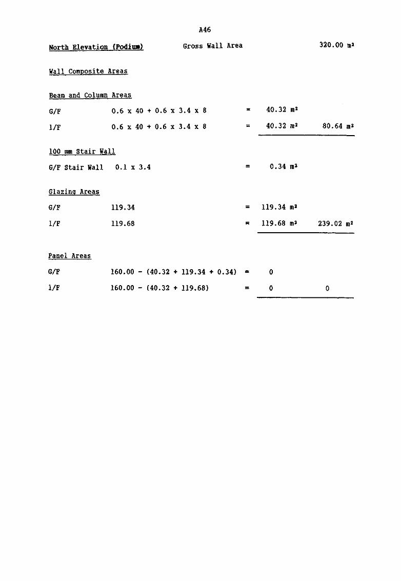
North Elevation (Podiua)
A46
Gross Wall Area
Wall Composite Areas
Beam and Column Areas
G/F 0.6 x 40 + 0.6 x 3.4 x 8
1/F 0.6 x 40 + 0.6 x 3.4 x 8
100 mm Stair Wall
G/F Stair Wall 0.1 x 3.4
Glazing Areas
G/F 119.34
1/F 119.68
Panel Areas
G/F
1/F
160.00 - (40.32 + 119.34 + 0.34) «
160.00 - (40.32 + 119.68) »
40.32 m*
40.32 m*
0.34
119.34 m*
119.68 m2
0
0
320.00 mz
80.64 m*
239.02
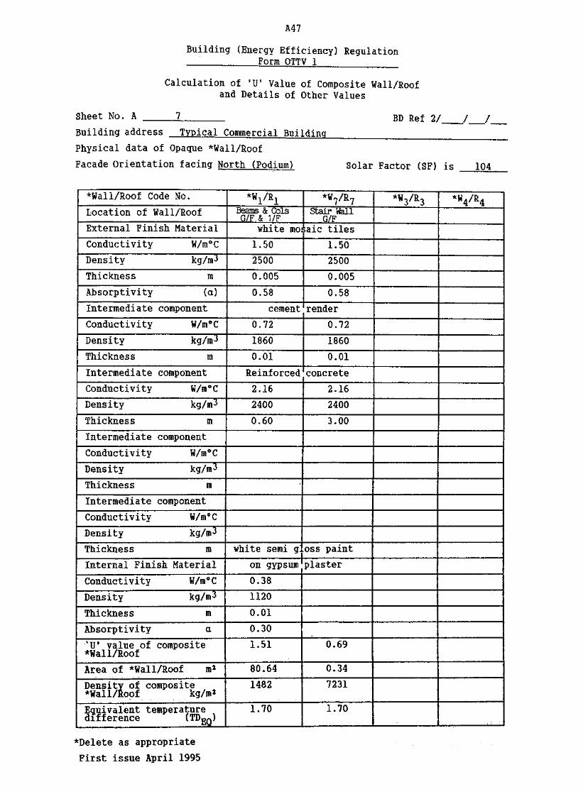
A47
Building (Energy Efficiency) RegulationForm QTTV 1 __
Calculation of 'U1 Value of Composite Wall/Roofand Details of Other Values
Sheet No. A 7
Building address Typical Commercial BuildingBD Ref 2/
Physical data of Opaque *Wall/Roof
Facade Orientation facing North (Podium) Solar Factor (SF) is 104
*Wall/Roof Code No.
Location of Wall/Roof
External Finish Material
Conductivity W/m°C
Density kg/m^
Thickness m
Absorptivity (a)
Intermediate component
Conductivity W/m°C
Density kg/m^
Thickness m
Intermediate component
Conductivity W/m°C
Density kg/m3
Thickness m
Intermediate component
Conductivity W/m0C
Density kg/ra3
Thickness m
Intermediate component
Conductivity W/m*C
Density kg/m3
Thickness m
Internal Finish Material
Conductivity W/m°C
Density kg/m3
Thickness m
Absorptivity a%Uf value of composite*Wal I/Roof
Area of *Wall/Roof m*
Density of composite*Wall/Roof kg/m2
Equivalent temperaturedifference ^TDEQ)
*WI/RIBeams & ColsG/F & 1/F
white moi
1.50
2500
0.005
0.58
cement
0.72
1860
0.01
Reinforced
2.16
2400
0.60
white semi g'.
on gypsum
0.38
1120
0.01
0.30
1.51
80.64
1482
1.70
*W?/R7Stair Wall
G/F;aic tiles
1.50
2500
0.005
0.58
render
0.72
1860
0.01
concrete
2.16
2400
3.00
oss paint
plaster
0.69
0.34
7231
1.70
*W3/R3 *W4/R4
*Delete as appropriate
First issue April 1995

A48
Building (Energy Efficiency) RegulationForm OTTV 2
Window/Rooflight Schedule
Sheet No, B BD Ref 2/ / /
Building address Typical CoBmercial Building
Physical data on *¥indow/rooflight
Facade Orientation facing North (Podium) Solar Factor (SF) is 104
iindow/Roof light Code No*
Location of *iindow/Roof light
Glazing type
Thickness m
Shading Coefficient (SO
Type of shading device
External ShadingMultiplier (ESM)
Area of glazing it2
*F1/RL1
G/F&l/Funshaded
plain
0.012
0.90_
—
239.02
*F,/Rlm4 «
*F3/RL3 *F4/RL4
Physical data on *window/rooflight
Facade Orientation facing Solar Factor is
iindov/Roof light Code No..
Location of *iindow/Roof light
.Glazing type
•.Thickness m
Shading Coefficient (SO
Type of shading device
External ShadingMultiplier (ESM)
Area of glazing n*
*F1/RL1 *F7/RL7£t &*F3/RL3 *F4/RL4
* Delete as appropriate
First issue April 1995
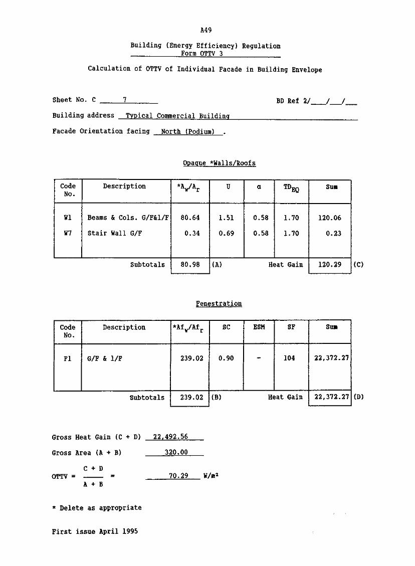
A49
Building (Energy Efficiency) RegulationForro OTTV 3
Calculation of OTTV of Individual Facade in Building Envelope
Sheet No. C BD lef 2/ / /
Building address Typical Commercial Building
Facade Orientation facing North (Podium)
Opaque *Walls/R0ofs
CodeNo.
Wl
W7
Description
Beams & Cols. G/F&l/F
Stair Wall G/F
Subtotals
*VAr
80.64
0.34
80.98
U
1.51
0.69
a
0.58
0.58
TDEQ
1.70
1.70
(A) Heat Gain
Sum
120.06
0.23
120.29 (C)
Fenestratipn
CodeNo.
Fl
Description
G/F & 1/F
Subtotals
*Afw/Afr
239.02
239.02
SC
0.90
ESM
-
SF
104
(B) Heat Gain
Su»
22,372.27
22,372.27 (D)
Gross Heat Gain (C + D) 22,492.56
Gross Area (A > B) 320.00
C + DOTTV =
A + B70.29
* Delete as appropriate
First issue April 1995

A50
West Elevation (Podiim) Gross Wall Area 366.00 m2
—— (with tiles = 112 m2)(Party wall = 208 m2)
Wall Composite Areas
Beam and Column Areas (with tiles)
G/F 0.6 x 14 + 0.6 (3.4 x 3) = 14.52 m2
1/F 0.6 x 14 + 0.6 (3.4 x 3) = 14.52 m2 29.04 m2
300 mm Ramp Wall
1/F 23 x 4 x 0.5 - 18.9 = 27.1 m2
Glazing Areas
G/F 41.48 = 41.48 m2
1/F 41.48 = 41.48 m2 82.96 m2
Beam and Column Areas (Party Wall and Ramp)
G/F 0.6 x 26 + 0.6 (3.4 x 5) » 25.80 m2
1/F 0.6 x 26 + 0.6 (3.4 x 5) « 25.80 m2
1/F Samp 0.6 x 23 + 0.6 (3.4 x 5 x 0.5) = 18.90 m2 70.50 m2
Panel Areas (with tiles)
G/F and 1/F 112.00 - (29.04 + 82.96)
Panel Areas in Party Wall
G/F and 1/F 208 - 51.60 = 156.40 m2 156.40 m2

A51
Building (Energy Efficiency) RegulationForm QTTV 1
Calculation of §U' Value of Composite Wall/Roofand Details of Other Values
Sheet No. A 8 BD Ref 2/
Building address Typical Commercial Building
Physical data of Opaque *Wall/Roof
Facade Orientation facing West (Podium) Solar Factor (SF) is 175
*Wall/Roof Code No.
Location of Wall/Roof
External Finish MaterialConductivity W/m°CDensity kg/m3
Thickness mAbsorptivity (a)Intermediate componentConductivity W/ift°CDensity kg/m3
Thickness m
Intermediate componentConductivity W/m°CDensity kg/m3
Thickness mIntermediate componentConductivity W/m°CDensity kg/m3
Thickness mIntermediate componentConductivity W/m°CDensity kg/m3
Thickness mInternal Finish Material
Conductivity W/m°CDensity kg/m3
Thickness mAbsorptivity a'IT value of composite*Wall/RoofArea of *Wall/Roof m2
Density of composite*Wall/Roof kg/m*Equivalent temperaturedifference (TDEQ)
*W1/R1Beans & ColsG/F & 1/F
white mosaictiles1.50
2500
0.005
0.58
cement render0.72
1860
0.01
Reinforced <2.16
2400
0.60
white semi g.on gypsum
0.38
1120
0.01
0.30
1.51
29.04
1482
2.10
*W1A/R1A •Beams & ColsG/F & 1/FReinforced
2.16
2400
0.60
0.65
:oncrete
oss paintplaster
0.38
1120
0.01
0.30
1.55
70.50
1451
2.10
*W3/R3ijaneisG/F & 1/FConcrete
2.16
2400
0.10
0.65
0.38
1120
0.01
0.30
2.41
156.40
250
4.35
*v%Harp vfell1/F
ReinforcedConcrete
2.16
2400
0.30
0.65
0.38
1120
0.01
0.30
1.97
27.1
731
2.10
*Delete as appropriateFirst issue April 1995

A52
Building (Energy Efficiency) RegulationForm QTTV 2
Window/Rooflight Schedule
Sheet No. B BD Ref 2/ /
Building address Typical Commercial Building
Physical data on *window/rooflight
Facade Orientation facing West (Podium) Solar Factor (SF) is 175
Window/Roof light Code No,
Location of *Window/Roof light
Glazing type
Thickness us
Shading Coefficient (SO
Type of shading device
External ShadingMultiplier (ESM)
Area of glazing ro2
*F1/RL1
G/F&l/Funshaded
plain
0.012
0.90
-
—
82.96
*F2/RL2 *F3/RL3 *F4/RL4
Physical data on *window/rooflight
Facade Orientation facing Solar Factor is
Hindov/Roof light Code Mo.
Location of *Iindow/Roof light
Glazing type
Thickness m
Shading Coefficient (SO
Type of shading device
External ShadingMultiplier (ESM)
Area of glazing m2
*F1/RL1 *F2/RL2 *F3/RL3 *F4/RL4
* Delete as appropriate
First issue April 1995

A53
Building (Energy Efficiency) RegulationForm OTTV 3
Calculation of OTTV of Individual Facade in Building Envelope
Sheet No. C BD lef 2/ / /
Building address Typical Commercial Building
Facade Orientation facing West (Podium)
Opaque ^Walls/Roofs
CodeNo.
Wl
W1A
W3
W5
Description
Beams & Cols. G/F&l/F
Beams & Cols. G/F&l/F
Panels G/F&l/F
Ramp Wall 1/F
Subtotals
*VAr
29.04
70.50
156.40
27.10
283.04
U
1.51
1.55
2.41
1.97
a
0.58
0.65
0.65
0.65
EQ
2.10
2.10
4.35
2.10
(A) Heat Gain
Sum
53.41
149.16
1,065.75
72.87
1,341.19 CO
Fenestration
CodeNo.
Fl
Description.
G/F & 1/F
Subtotals
*Af¥/Afr
82.96
82.96
SC
0.90
ESM
-
SF
175
(B) Heat Gain
Sum
13,066.20
13,066.20 CO)
Gross Heat Gain (C + D) 14,407*39
Gross Area (A + B) 366,00
C + DOTTV =
A + B39,36
* Delete as appropriate
First issue April 1995

154
South.Elevation (Podiu») Gross Wall Area 264.49 m*
Wall Composite Areas
Beam and Column Areas
G/F - = -
1/F 0.6 x 34.6 + 0.6 (3.4 x 8} » 37.08 m2 37.08 m2
1/P Stair Wall 0.1 x 3.4 - 0.34 m2 0.34 m2
Glazing Areas
G/F ~ = -
1/F 100.98 = 100.98 m2 100.98 m2
Eaisp
1/F 5.4 x 23.35 = 126.09 m2 126.09
External wall at rarop omitted 5.4 x 40 » 21.60 m2
Panel Areas
G/F ' . - =
1/F 160.00 - (37.08 + 0.34 + 100.98 + 21.60) «

A55
Building (Energy Efficiency) RegulationForm OTTV 1
Calculation of SU' Value of Composite Hall/Roofand Details of Other Values
Sheet No. A 9
Building address Typical Commercial BuildingBD Ref 2/ / /
Physical data of Opaque *WalI/Roof
Facade Orientation facing South (Podium) Solar Factor (SF) is 191
*Wal I/Roof Code Mo.
Location of Wall/Roof
External Finish Material
Conductivity W/m°C
Density kg/m^
Thickness m
Absorptivity (a)
Intermediate component
Conductivity S/»°C
Density kg/ir5
Thickness m
Intermediate component
Conductivity W/m°C
Density kg/us J
Thickness m
Intermediate component
Conductivity W/m°C
Density kg/mj
Thickness m
Intermediate component
Conductivity W/m°C
Density kg/m-5
Thickness m
Internal Finish Material
Conductivity W/m°C
Density kg/mj
Thickness mAbsorptivity a%Uf value of composite*Wall/Roof
Area of *Wall/Roof m2
Density of composite*Wall/Raof kg/1*
Equivalent temperaturedifference (TDEQ)
*VR1Beams & Cols
1/Fwtiite mosaic
tiles1.50
2500
0.005
0.58
cement render0.72
1860
0.01ReinforcedConcrete
2.16
2400
0.60
white semi g
on gypsum0.38
1120
0.01
0.30
1.51
37.08
1482
1.40
*V*5Ranp 1/F
r. concrete
2.16
2400
0.30
0.65
loss paint
Blaster0.38
1120
0.01
0.30
1.97
126.09
731
4.10
*W7/R?Stair Wall
1/Fwnite ncsaic
tiles1.50
2500
0.005
0.58
cement render0.72
1860
0.01ReinforcedConcrete
2.16
2400
3.00
0.69
0.34
7231
1.40
*W /R
*Delete as appropriate
First issue April 1995

A56
Building (Energy Efficiency) RegulationForm QTTV 2
Windov/Rooflight Schedule
Sheet No. B BD Ref 2/ / /
Building address Typical Commercial Building..
Physical data on *window/rooflight
Facade Orientation facing South (Podiuii) Solar Factor (SF) is 191
Window/Roof light Code No*
Location of *Window/Roof light
Glazing type
Thickness n
Shading Coefficient (SO
Type of shading device
External ShadingMultiplier (ESM)
Area of glazing ra2
*P1/RL1
1/Funshaded
plain
0.012
0.90
-
—
100.98
*F2/RL2 *F3/RL3 *F4/RL4
Physical data on *vindo¥/rooflight
Facade Orientation facing Solar Factor is
lindow/Roof light Code No.
Location of *iindow/Rooflight
Glazing type
Thickness in
Shading Coefficient (SC)
Type of shading device
External ShadingMultiplier (BSM)
Area of glazing m*
*F1/RL1 *F2/RL2 *F3/RL3 *F4/RL4
* Delete as appropriate
First issue April 1995

A57
Building (Energy Efficiency) RegulationForm QTTV 3
Calculation of OTTV of Individual Facade in Building Envelope
Sheet No. C BD let 2/ / /
Building address Typical Commercial Building
Facade Orientation facing South (Podium)
Opaque *WalIs/Roofs
CodeNo.
Wl
W2
W3
Description
Beams and Cols G/F&l/F
Stair Wall 1/F
Ramp 1/F
Subtotals
*V*r
37.08
0.34
126.09
163.51
U
1.51
0.69
1.97
a
0.58
0.58
0.65
TDEQ
1.40
1.40
4.10*
(A) Heat Gain
SUffi
45.46
0.19
611.98
657.63
* Value interpolated from vert* and horizontal conponents,
(C)
Fenestration
CodeNo.
PI
Description
1/F
Subtotals
*Af¥/Afr
100.98
100.98
SC
0.90
ESM
-
SF
191
(B) Heat Gain
Sun
17,358.46
17,358.46 (1)
Gross Heat Gain (C + D) 18.016.09
Gross Area (A + B) 264.49
C + DOTTV = 68.12 W/n*
A + B
* Delete as appropriate
First issue April 1995

A58
Building (Energy Efficiency) RegulationForm OTTV 4
Summary of OTTV of Building Envelope
Sheet No. D
Building address Typical Commercial Building
BD Ref. 2/
Total Envelope Heat Gain (*Tower/Podium)
FacadeOrientation
a. East
b. North
c. West
d. South
e.
f.
Subtotal
Roof
'a. Main
b.. 15/F
Subtotal
Gross Areafront
Fora OTTV3
344.00
320.00
366.00
264.49
1,294.49 (E)
Carpark under - nc
(F)
Gross HeatGain fromForm OTTV3
31,629.06
22,492.56-
14,407.39
18,016.09
86,545.10 (6)
>n accountable
(H)
*Tower/Podium Walls OTTV = — = 66.86 W/m*E
H*Tower/Podium Roofs OTTV = — =
FW/JB*
G + H*Tower/Podium OTTV =
E + FW/m*
* Delete as appropriate
First issue April 1995


HK 693.832 C66
Code of practice forI 1 1 "Hio-rtno 1
/J • "_"?' """" "
Ml1
1
T /•/i LC J "fc,-T--- -A!N
1
