unit 13tiger.ee.nctu.edu.tw/course/logicdesign2017fall/lec13.pdfunit 13 clocked sequential ckt 2...
TRANSCRIPT
UNIT 13ANALYSIS OF CLOCKED SEQUENTIAL CIRCUITS
Spring 2011

© Iris H.-R. Jiang
Clocked Sequential Circuits
Contents Analysis by signal tracing & timing charts State tables and graphs General models for sequential circuits A sequential parity checker
Reading Unit 13
Clocked sequential ckt
2
Basic unitUnit 11: Latch & FFs
Simple sequential CktUnit 12: Registers & Counters
Complex sequential CktUnits 13-15: FSM
Put it all togetherUnit 16: Summary
Basically, no inputs

© Iris H.-R. Jiang
Analysis of Clocked Sequential Circuits
Find the output sequence resulting from a given input one⇒ Draw a timing chart to show inputs, clock, FF states, outputs1. Assume an initial state of FFs (reset to 0)2. Determine the circuit outputs & FF inputs for 1st input pattern3. Determine the new FF states after the next active clock edge4. Determine the outputs for the new states5. Repeat 2—4 for each input pattern
Clocked sequential ckt
3
Current states
…A
Clock
Next states
…A+
Clock
Clock trigger
Current inputs
Current outputs

Two Types of Sequential Circuits & their Timing Charts4
Clocked sequential ckt

© Iris H.-R. Jiang
Type I: Moore Machine
Moore machine: the output depends only on the present state The output which corresponds to a given input appears until after
the active clock edge
Clocked sequential ckt
5
B
DB
B′A
DA
A′
ClockClock
Z = A ⊕ B
AX B′ X
Clock
A
B
Z
X
1 1 0 1 0(0)
(0)
(0)
(0)
0 1 1 0 1
1
0
1
0
1
1

© Iris H.-R. Jiang
Type II: Mealy Machine
Mealy machine: the output depends on both the present state and on the inputs False outputs may occur Glitches and spikes
6
Clock
A
B
Z
X
1 0 0 11
0 1 0 11
“False” 1 output“False” 0 outputClocked sequential ckt
JB
B′
KB
B
CKJA
A′
KA
A
CK
Clock
X AX
ClockX X
B
B
B′ZX
AX′A′
X
(0)
(0)
0
1
0
1
1
1

State Tables and Graphs7
Clocked sequential ckt

© Iris H.-R. Jiang
How to Construct the State Table?
The state table specifies
Procedure to construct the state table for a given circuit1. Determine the flip-flop input equations and the output equations
from the circuit2. Derive the next-state equation for each FF from its input
equations3. Plot a next-state map for each flip-flop4. Combine these maps to form the state table
Clocked sequential ckt
8
Next stateOutput
Present stateInput
© Iris H.-R. Jiang
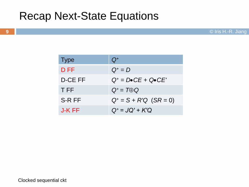
Recap Next-State Equations
Clocked sequential ckt
9
Type Q+
D FF Q+ = DD-CE FF Q+ = D•CE + Q•CE'T FF Q+ = T⊕QS-R FF Q+ = S + R'Q (SR = 0)J-K FF Q+ = JQ′ + K′Q

© Iris H.-R. Jiang
Example: Moore Machine (1/2)
1. DA = X ⊕ B′ DB = A + XZ = A ⊕ B
10
B
DB
B′A
DA
A′
ClockClock
Z
AX B′ X
XAB 0 1
01
11
10
00
0
0
1
1
1
1
0
0
A+
XAB 0 1
01
11
10
00
0
1
1
1
0
1
1
1
B+
2. A+ = X ⊕ B′B+ = A + X
4.
3.
AB00011110
A+B+
X = 0 X = 110000111
01111101
Z0101

© Iris H.-R. Jiang
Example: Moore Machine (2/2)
Clocked sequential ckt
11
AB00011110
A+B+
X = 0 X = 110000111
01111101
Z0101
Present stateS0S1S2S3
Next stateX = 0 X = 1S3S0S1S2
S1S2S2S1
Presentoutput (Z)
0101
State assignment
S3
1
S2
0
S0
0
S1
1
0 1
01
1
0
1
0
Clock
A
B
Z
X
1 1 0 1 0(0)
(0)
(0)
(0)
0 1 1 0 1
1
0
1
0
1
1

© Iris H.-R. Jiang
Example: Mealy Machine (1/3)12
JB
B′
KB
B
CKJA
A′
KA
A
CK
Clock
X AX
ClockX X
B
1.&2. A+ = JAA′ + KA′A = XBA′ + X′AB+ = JBB′ + KB′B = XB′ + (AX)′B
= XB′ + A′B + X′BZ = X′A′B + XA +XB′
3.X
AB 0 1
01
11
10
00
1
0
0
0
0
1
1
1
Z
XAB 0 1
01
11
10
00
0
1
1
1
0
0
0
0
A+
XAB 0 1
01
11
10
00
1
1
0
1
0
0
1
1
B+B
B′ZX
AX′A′
X

© Iris H.-R. Jiang
Example: Mealy Machine (2/3)
Clocked sequential ckt
13X
AB 0 1
01
11
10
00
1
0
0
0
0
1
1
1
Z
XAB 0 1
01
11
10
00
0
1
1
1
0
0
0
0
A+
XAB 0 1
01
11
10
00
1
1
0
1
0
0
1
1
B+
S1
S0
S2 S3
0/0
1/11/1 0/0
0/11/0
1/1
0/0
AB00011110
A+B+
X = 0 X = 100011110
01110001
0100
4. ZX = 0 X = 1
1011
State assignment
Present stateS0S1S2S3
Next stateX = 0 X = 1S0S1S2S3
S1S2S0S1
Presentoutput (Z)X = 0 X = 1
0100
1011
State graph

© Iris H.-R. Jiang
Example: Mealy Machine (3/3)14
Clock
A
B
Z
X
1 0 0 11
0 1 0 11
“False” 1 output“False” 0 output
S1
S0
S2 S3
0/0
1/11/1 0/0
0/11/0
1/1
0/0
Clocked sequential ckt
(0)
(0)
0
1
0
1
1
1

© Iris H.-R. Jiang
Example: Serial Adder15
yi ci ci+1xi si
0 10 011 10 001 00 11
0 01 11
0 00 00
1 11 11
0 11 00
1 01 10
FullAdder
xi
yi
cici+1
si
Q′ CK
Q D
Clock
S0 S1
00/0,01/1,10/1 01/0,10/0,11/1
11/000/1xi yi /si
0 0 1 11
Clock
yi
ci
ci+1
si
xi
Carry_out (ci+1) is latched in the DFFThe latched Carry_out will be added with the next xi and yi
glitch
S0: ci=0; S1: ci=1
© Iris H.-R. Jiang
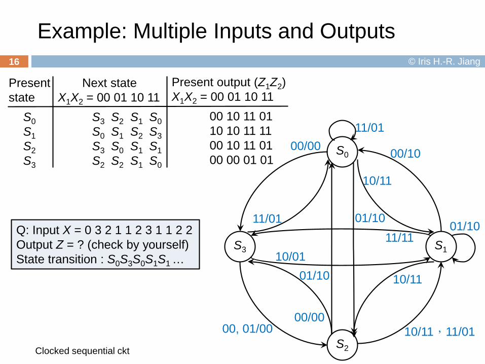
Example: Multiple Inputs and Outputs
Clocked sequential ckt
16
11/01
S1
S2
S0
S3
00/00
11/01 01/10
10/11
00/10
11/1110/01
00, 01/0000/00
01/10 10/11
10/11,11/01
01/10Q: Input X = 0 3 2 1 1 2 3 1 1 2 2Output Z = ? (check by yourself)State transition : S0S3S0S1S1 …
Present state
S0S1S2S3
Next stateX1X2 = 00 01 10 11
S3S0S3S2
S2S1S0S2
Present output (Z1Z2)X1X2 = 00 01 10 11
00 10 11 0110 10 11 1100 10 11 0100 00 01 01
S1S2S1S1
S0S3S1S0

Moore vs. Mealy
General Models17
Clocked sequential ckt

© Iris H.-R. Jiang
General Model for Mealy Machines
An output is a functionof states and inputs
Clocked sequential ckt
18
Clock
Combinational Subcircuit
Z2
Zn
Z1
Q2
Qk
Q1
X2
Xm
X1
Q2
Qk
Q1
CK
CK
CK
Q2+
Qk+
Q1+
D2
Dk
D1
………
…… …

© Iris H.-R. Jiang
General Model for Moore Machines
An output is a function of only states
Clocked sequential ckt
19
Clock
Combinational Subcircuit
(For Outputs)
Q2
Qk
Q1
X2
Xm
X1
Q2
Qk
D2
CK
CK
CK
Q2+
Qk+
Q1+ Q1
Dk
D1Combinational
Subcircuit(For Flip-Flop
Inputs)
Z2
Zn
Z1
…
…
… …
…
… …
… …
…

Case Study: A Sequential Parity Checker20
Clocked sequential ckt

© Iris H.-R. Jiang
Parity Checker (1/3)
Error detection: add an extra bit (parity bit) when transmitting or storing binary data When the total # of 1 bits in the block (data bits + parity bit) is odd
(even), we say the parity is odd (even)
Clocked sequential ckt
21
Odd parity
0000000 10000001 00110110 11010101 10111000 0
Even parity
0000000 00000001 10110110 01010101 00111000 1
Data bits Parity bits

© Iris H.-R. Jiang
Parity Checker (2/3)
Design an odd-parity checker Z=1 if total # of 1’s is odd Z=0 if total # of 1’s is even Z=0 ⇒ an error occurs in odd-parity protocol Initially, Z = 0
Timing chart of the odd parity checker (active-low)
Clocked sequential ckt
22
Clock
Z=Q
X 0 0 1 1 0 1 01
ParityChecker
X(Data Input)
Z
Clock
© Iris H.-R. Jiang
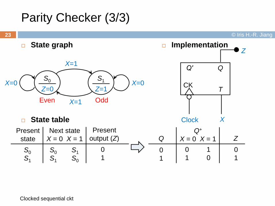
Parity Checker (3/3)
State graph
State table
Clocked sequential ckt
23
Q
CK T
Q′
XClock
Z Implementation
S1
Z=1S0
Z=0
X=1
X=0
X=1
X=0
Even Odd
Present stateS0S1
Next stateX = 0 X = 1S0S1
S1S0
Presentoutput (Z)
01
Q
01
Q+
X = 0 X = 1 Z01
01
10