unit operations of water treatment -...
TRANSCRIPT

P - A - R - T • 2
UNIT OPERATIONS OFWATER TREATMENT

This page is
intentionally blank

CHAPTER 8COAGULATION AND
FLOCCULATION
The processes of coagulation and flocculation are employed to separate suspendedsolids from water whenever their natural subsidence rates are too slow to provideeffective clarification. Water clarification, lime softening, sludge thickening, anddewatering depend on correct application of the theories of coagulation and floc-culation for their success.
Taking surface water clarification as an example, turbid raw water containssuspended matter—both settleable solids, particles large enough to settle quies-cently, and dispersed solids, particles which will not readily settle. A significantportion of these nonsettleable solids may be colloidal. Each particle is stabilizedby negative electric charges on its surface, causing it to repel neighboring particles,just as magnetic poles repel each other. Since this prevents these charged particlesfrom colliding to form larger masses, called floes, they do not settle. Coagulationis the destabilization of these colloids by neutralizing the forces that keep themapart. This is generally accomplished by adding chemical coagulants and applyingmixing energy. Aluminum salts, iron salts, or polyelectrolytes are the chemicalsusually used.
Figure 8.1 illustrates how these chemicals reduce the electric charges on col-loidal surfaces, allowing the colloidal particles to agglomerate into floes. Theseinitially small floes join, creating larger, settleable agglomerates. The destabiliza-tion step is coagulation (charge neutralization); the floe-building stage isflocculation.
The terms coagulation and flocculation are often used interchangeably; how-ever, when seen as two different mechanisms they can provide a better under-standing of clarification and dewatering.
COAGULATION
Colloidal species encountered in raw water and wastewater include clay, silica,iron and other heavy metals, color, and organic solids such as the debris of deadorganisms. Colloids may also be produced in precipitation processes such as limesoftening. Oil in wastewater is frequently colloidal.
Among the wide variety of colloidal materials in water, there is a broad dis-tribution of particle sizes. Table 8.1 shows how particle size affects the tendencyof particles to settle in quiet water. Colloids always require coagulation to achieve

FIG. 8.1 (a) Coagulation: The addition of a coagulant neutralizescharges, collapsing the "cloud" surrounding the colloids so they canagglomerate, (b) Flocculation: The bridging of the flocculant chemicalbetween agglomerated colloidal particles forms large settleable floes.
an effective size and settling rate; but even larger particles, which are not trulycolloidal and would settle if given enough time, may require coagulation to formlarger, faster settling floe.
When insufficient settling time is available in a treatment plant to remove sys-pended solids, coagulation and flocculation may cause them to grow in size andsettle rapidly enough to overcome the physical limitation of the plant design.
Colloids are categorized as hydrophobic (water hating) or hydrophilic (waterloving). Hydrophobic colloids do not react with water; most natural clays arehydrophobic. Hydrophilic colloids react with water; the organics causing color arehydrophilic. Of importance in water treatment, the hydrophiloc colloids may
TABLE 8.1 Sedimentation of Small Particles of Silica of 2.65 Sp. Gr.
Effectiveradius
Colloid
Typical
GravelCoarse sandFine sand
SiltBacteriaColloidal matter
mm
10.1.0.10.010.0010.0001
^m
10,0001,000100
101.0.1
Surface area(total)
3.14cm2
31.4cm2
314cm2
0.314m2
3.14m2
31.4m2
Settling time,1 m fall
1 S
10s125s108 min180hr755 days
NOTE: Particles larger than 100 ̂ m are visible to the naked eye and are considered to be settleablesolids. In the range of 10-100 nm, they are considered to be turbid. Below 10 /*m they are consideredcolloidal. Particles larger than 0.1 /*m are visible by light microscope; below 0.1 ^m, the electron micro-scope is used for detection.
Coag
ulan
tad
ditio
n
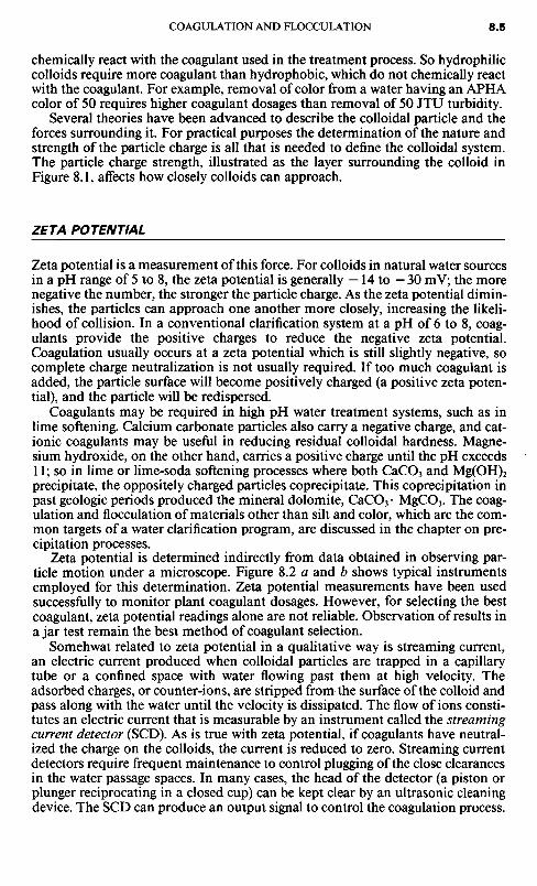
chemically react with the coagulant used in the treatment process. So hydrophiliccolloids require more coagulant than hydrophobic, which do not chemically reactwith the coagulant. For example, removal of color from a water having an APHAcolor of 50 requires higher coagulant dosages than removal of 50 JTU turbidity.
Several theories have been advanced to describe the colloidal particle and theforces surrounding it. For practical purposes the determination of the nature andstrength of the particle charge is all that is needed to define the colloidal system.The particle charge strength, illustrated as the layer surrounding the colloid inFigure 8.1, affects how closely colloids can approach.
ZETA POTENTIAL
Zeta potential is a measurement of this force. For colloids in natural water sourcesin a pH range of 5 to 8, the zeta potential is generally —14 to —30 mV; the morenegative the number, the stronger the particle charge. As the zeta potential dimin-ishes, the particles can approach one another more closely, increasing the likeli-hood of collision. In a conventional clarification system at a pH of 6 to 8, coag-ulants provide the positive charges to reduce the negative zeta potential.Coagulation usually occurs at a zeta potential which is still slightly negative, socomplete charge neutralization is not usually required. If too much coagulant isadded, the particle surface will become positively charged (a positive zeta poten-tial), and the particle will be redispersed.
Coagulants may be required in high pH water treatment systems, such as inlime softening. Calcium carbonate particles also carry a negative charge, and cat-ionic coagulants may be useful in reducing residual colloidal hardness. Magne-sium hydroxide, on the other hand, carries a positive charge until the pH exceeds11; so in lime or lime-soda softening processes where both CaCO3 and Mg(OH)2precipitate, the oppositely charged particles coprecipitate. This coprecipitation inpast geologic periods produced the mineral dolomite, CaCO3- MgCO3. The coag-ulation and flocculation of materials other than silt and color, which are the com-mon targets of a water clarification program, are discussed in the chapter on pre-cipitation processes.
Zeta potential is determined indirectly from data obtained in observing par-ticle motion under a microscope. Figure 8.2 a and b shows typical instrumentsemployed for this determination. Zeta potential measurements have been usedsuccessfully to monitor plant coagulant dosages. However, for selecting the bestcoagulant, zeta potential readings alone are not reliable. Observation of results inajar test remain the best method of coagulant selection.
Somehwat related to zeta potential in a qualitative way is streaming current,an electric current produced when colloidal particles are trapped in a capillarytube or a confined space with water flowing past them at high velocity. Theadsorbed charges, or counter-ions, are stripped from the surface of the colloid andpass along with the water until the velocity is dissipated. The flow of ions consti-tutes an electric current that is measurable by an instrument called the streamingcurrent detector (SCD). As is true with zeta potential, if coagulants have neutral-ized the charge on the colloids, the current is reduced to zero. Streaming currentdetectors require frequent maintenance to control plugging of the close clearancesin the water passage spaces. In many cases, the head of the detector (a piston orplunger reciprocating in a closed cup) can be kept clear by an ultrasonic cleaningdevice. The SCD can produce an output signal to control the coagulation process.

FIG. 8.2 (a) The "Zeta-Reader," an instrument for continuously observingthe mobility of particles in water and measuring zeta potential. (Courtesy ofKomline-Sanderson Engineering Corporation.) (b) The Mobility Meter is abench-type instrument for observation and measurement of average mobility.This is translatable to zeta potential by a standard factor. (Courtesy of PaperChemistry Laboratory, Inc.)
One of the variables that needs study in each system is the time factor; the speedor rate of charge neutralization varies with the type of colloid present and withtemperature. Therefore, a sample taken immediately after coagulant addition isusually inadequate. Typically, an equilibration time of 5 to 10 min is neededbefore putting the sample through the SCD.

Mixing is required to supplement coagulant addition to destroy stability in thecolloidal system. For particles to agglomerate they must collide, and mixing pro-motes collision. Brownian movement, the random motion imparted to small par-ticles by bombardment by individual water molecules, is always present as a nat-ural mixing force. However, additional mixing energy is almost always required.High intensity mixing, which distributes the coagulant and promotes rapid colli-sions, is most effective. The frequency and number of particle collisions are alsoimportant in coagulation. In a low turbidity water, the addition of solids such asclay or the recycle of previously settled solids may be required to increase thenumber of particle collisions.
FLOCCULATION
The floe formed by the agglomeration of several colloids may not be large enoughto settle or dewater at the desired rate. A flocculant gathers together floe particlesin a net, bridging from one surface to another and binding the individual particlesinto large agglomerates as shown in Figure 8.3. Alum, iron salts, and high molec-ular weight polymers are common flocculants. Flocculation is promoted by slowmixing, which brings the floes gently together; too high a mixing velocity tearsthem apart, and they seldom re-form to their optimum size and strength. Floc-culation not only increases the size of floe particles, but it also affects the physicalnature of the floe. Sludges and slurries, when flocculated, dewater at faster rateson sand beds and in mechanical dewatering equipment because of the less gelat-inous structure of the floe.
FIG. 8.3 Photomicrographs illustrating the coagulation process. (Left) Turbid river water, show-ing fine dispersion of tiny solid particles. (Right) Same water treated with coagulant. Particles are"collected" in the floe. (130 X)

It is apparent that the processes of (a) charge neturalization, or coagulation,and (b) floe building, or flocculation, are so different that each system containingthe chemically treated solids being processed has its own physical constraints.These are outlined in Table 8.2.
In an attempt to develop a mathematical procedure to express some of thesevariables, hydraulic engineers have examined this problem of fluid mechanics andhave developed the concepts of velocity gradient and shear rate, or "G factor."
G- FACTOR (shear rate) = °'^n* = 25 s~1
FIG. 8.4 Illustration of velocity gradient and shear rate.
Figure 8.4 illustrates the basis of these concepts. In this illustration, the differen-tial velocity between two particles 0.01 ft apart is 0.25 ft/s, so the shear rate G is25 s"1. Obviously, it is impractical to measure the G factor in this way, but for-tunately further development of the mathematical model shows that shear rate isalso related to rate of energy input (power) per unit volume (equivalent to deten-tion time in the process) and water viscosity. The latter has a direct bearing onthe frequency of particle collisions and explains, in part, the strong influence ofwater temperature on both coagulation and flocculation. The formula is:
Ip/VG factor= \ / — ins'1V M
where P is power input, in ft Ib/s (hp X 550) (watts)V is volume in the process, ft3 (m3)/LI is viscosity, in (Ib) (s)/ft2 (viscosity in centipoises X 2.1 X 10~5 = (lb)(s)/ft2)
The G factor usually recommended for most coagulation units is about 900 s~l
for a 30-s mixing time, varying inversely with time. The required mixing time is
Variable condition
Nature of solids
Type of chemical applied
Energy requirementVelocity gradientTime in process
Coagulation
Numerous, fineparticulates
Low molecular weightcharge neutralizer
Rapid mixingHighSeconds
Flocculation
Scattered, large gels
High molecular weightparticle binder
Slow stirringLowMinutes
TABLE 8.2 Constraints between Coagulation and Flocculation
usually established by bench tests, as described later. The recommended G factorfor flocculation is lower, varying from about 50 for a cold, colored water carryinga very fragile floe, to about 200 for a solids contact lime softener on warm riverwater. Again, the G factor for flocculation must be determined by bench testing,and this should lead to a design of flocculator which can be varied in speed andpower input as river conditions change and lead to fluctuations in solids concen-tation and sensitivity of floe to shear.
COAGULA TION AND FLOCCULA TION CHEMICALS
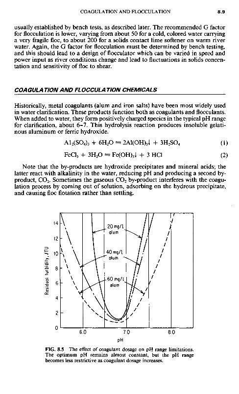
Historically, metal coagulants (alum and iron salts) have been most widely usedin water clarification. These products function both as coagulants and flocculants.When added to water, they form positively charged species in the typical pH rangefor clarification, about 6-7. This hydrolysis reaction produces insoluble gelati-nous aluminum or ferric hydroxide.
A12(SO4)3 + 6H2O — 2Al(OH)3I + 3H2SO4 (1)
FeCl3 + 3H2O - Fe(OH)3J + 3 HCl (2)
Note that the by-products are hydroxide precipitates and mineral acids; thelatter react with alkalinity in the water, reducing pH and producing a second by-product, CO2. Sometimes the gaseous CO2 by-product interferes with the coagu-lation process by coming out of solution, adsorbing on the hydrous precipitate,and causing floe flotation rather than settling.
FIG. 8.5 The effect of coagulant dosage on pH range limitations.The optimum pH remains almost constant, but the pH rangebecomes less restrictive as coagulant dosage increases.
Res
idua
l tu
rbid
ity,
JTU

Polyaluminum chloride, a product in wide use in Japan, avoids the problemof alkalinity reduction. When the material hydrolyzes, the floe formed incorpo-rates the chloride ion into the floe structure so it is not available to produce acid,reduce alkalinity, and form by-product CO2. Even if there are no suspended solidsin the water initially, the metal coagulants form floes which enmesh the destabi-lized colloids. However, the voluminous sludges produced by the addition ofmetal coagulants create disposal problems because they are usually difficult todewater. This is why alum and iron salts are not often used to improve efficiencyof centrifuges, filter presses, and other dewatering devices.
Metal coagulants are particularly sensitive to pH and alkalinity. If pH is notin the proper range, clarification is poor, and iron or aluminum may be solubi-lized and cause problems to the water user. The lower the coagulant dosage, themore sensitive the floe is to pH changes (Figure 8.5). Table 8.3 lists some impor-tant properties of common coagulants.
The introduction of activated silica in the 1940s significantly improved theperformance of alum and iron salts as coagulants and flocculants in water clari-fication. The subsequent development of a variety of organic polymers calledpolyelectrolytes in the next decade was an even more spectacular contribution towater treatment technology.
Polyelectrolytes are large water-soluble organic molecules made up of smallbuilding blocks called monomers, repeated in a long chain. They usually incor-porate in their structures ion exchange sites which give the molecule an ioniccharge. Those having a positive charge are cationic, and those with a negativecharge are anionic. These molecules react with colloidal material in the water byneutralizing charge or by bridging (tying together) individual particles to form avisible, insoluble precipitate or floe.
TAILORING POLYELECTROLYTES
The performance of these materials can be modified to suit the nature of the col-loidal matter to be removed from the water. These modifications include varia-
Common name
Alum
Lime
Ferric chloride
Ferric sulfateCopperasSodium aluminate
Formula
A12(S04)3- 14H2O
Ca(OH)2
FeCl3 -6H2O
Fe2(SO4), -3H2OFeSO4-TH2ONa2Al2O4
Equiv.weight
100
40
91
51.5139100
pHat1%
3.4
12
3-4
3-43-4
11-12
Availability
Lump— 17% Al2O3
Liquid— 8.5% Al2O3
Lump — as CaOPowder— 93-95%Slurry— 15-20%Lump— 20% FeLiquid— 20% FeGranular— 18. 5% FeGranular — 20% FeFlake— 46% Al2O3
Liquid— 26% Al2O3
TABLE 8.3 Properties of Common Coagulants

tions in molecular weight and ion exchange capacity. These materials can also beproduced without an ionic charge; these are called nonionic polymers. Althoughthey are not, strictly speaking, polyelectrolytes, nonionic polymers exhibit manyof the same flocculating properties in solution, and are generally considered aspart of the general polyelectrolyte family of compounds.
Although most polyelectrolytes are synthetic organic materials, nature alsoproduces an endless variety of such materials. Some of these are chemically pro-cessed to improve performance and are commercially available.
The cationic polyelectrolytes are either polyamines or quaternary amines. Inwater, a polyamine hydrolyzes as follows:
RX RXNH + H2O- NH-H+ + OH-
R' R'
Because of the hydrolysis to yield OH ~, at high pH, the reaction is forced tothe left, and the polymer becomes nonionic. This is illustrated by Figure 8.6,which shows loss in exchange capacity for a specific polyamine as pH increases.
FIG. 8.6 Generalized plot showing loss of cationicstrength for tertiary polyamines as pH increases, andrelative pH independence of quaternary aminecoagulants.
In contrast, the quaternary polymers are but slightly affected by pH, remainingpositively charged over a broad pH range (Figure 8.6).
The anionic polymers incorporate a carboxyl group (—COOH) in their struc-ture. These ionize in the following manner:
R-COOH - R-COO- + H+
The hydrogen ion forces the reaction to the left, so anionics become nonionicat low pH.
The ionic nature of polyelectrolytes is only one factor determining the perfor-mance of these materials as coagulants and flocculants. Other factors, such as thepolar nature of nonionic bonds in the molecule, molecular size, and moleculargeometry, also play a large part and may in some cases overshadow the effects ofcharge and charge density. Hence, high molecular weight nonionic polymers are
Tertiary polyamine
Quaternarypolyamine'
Coa
gula
nt
char
ge(e
xcha
nge
capa
city
)
effective flocculants in many systems because of their ability to attract and holdcolloidal particles at polar sites on the molecule. Furthermore, because of theirmolecular size, they can bridge together many small particles. Less sludge is gen-erated by organic polymers than by inorganic salts, since they do not add weightor chemically combine with other ions in the water to form a precipitate. Organicpolymers do not affect the pH of the water and generally do not require pH adjust-ment for effective use.
So, as a general rule, cationics are designed to work at lower pH values, anion-ics at higher. Nonionics and quaternaries are only slightly infleunced by pH. Thegeneral rule should not be interpreted to mean that anionic polymers do not workat low pH value; it simply means they are no longer ionic. They may producegood results in flocculating solids at low pH simply because of their nonionicbonds. The same applies to cationics; even though they are not charged at highpH, they may act as effective coagulants because of their polar groups.
Organic polymers overcome many of the problems inherent in the use of alumor iron salts. These polymers are long chain organic molecules made up of smallbuilding blocks, called monomers, repeated along the chain. Depending on theselection of monomers and processing methods, a wide variety of polymers canbe made of various configurations and molecular weights. Molecular weight isproportional to polymer chain length; the wide selection of structures and molec-ular weights makes it possible to design a polymer specifically for a given coagu-lation or flocculation problem, but this is seldom practical for economic reasons.
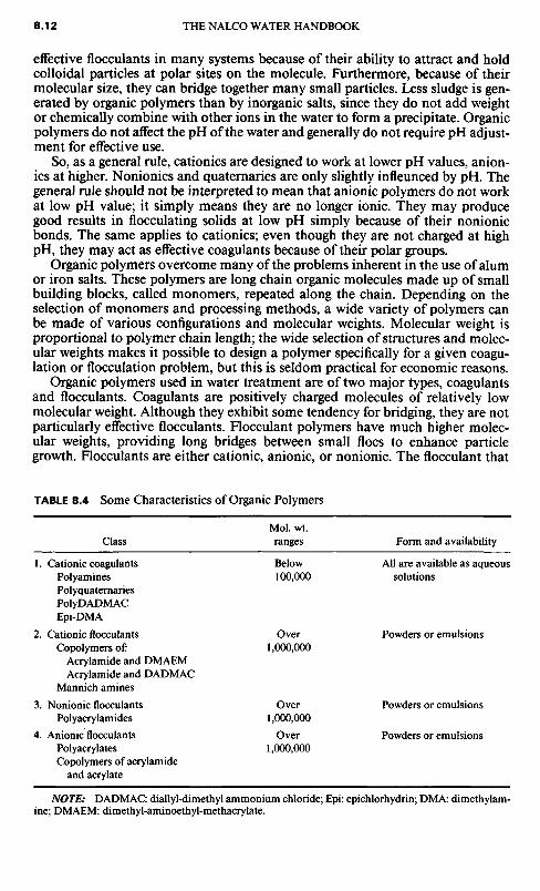
Organic polymers used in water treatment are of two major types, coagulantsand flocculants. Coagulants are positively charged molecules of relatively lowmolecular weight. Although they exhibit some tendency for bridging, they are notparticularly effective flocculants. Flocculant polymers have much higher molec-ular weights, providing long bridges between small floes to enhance particlegrowth. Flocculants are either cationic, anionic, or nonionic. The flocculant that
TABLE 8.4 Some Characteristics of Organic Polymers
Class
1. Cationic coagulantsPolyaminesPolyquaternariesPoIyDADMACEpi-DMA
2. Cationic flocculantsCopolymers of:
Acrylamide and DMAEMAcrylamide and DADMAC
Mannich amines
3. Nonionic flocculantsPolyacrylamides
4. Anionic flocculantsPolyacrylatesCopolymers of acrylamide
and acrylate
MoI. wt.ranges
Below100,000
Over1,000,000
Over1,000,000
Over1,000,000
Form and availability
All are available as aqueoussolutions
Powders or emulsions
Powders or emulsions
Powders or emulsions
NOTE: DADMAC: diallyl-dimethyl ammonium chloride; Epi: epichlorhydrin; DMA: dimethylam-ine; DMAEM: dimethyl-aminoethyl-methacrylate.
works best in any system can be determined only through laboratory screeningand in-plant testing. Polymer flocculants, unlike coagulants, are not selected forneutralization. Table 8.4 lists some characteristics of commonly used organiccoagulants and flocculants used in water treatment.
Unlike inorganic salts, polymers do not produce voluminous, gelatinous floe.In applications where additional solids improve results, inorganic coagulants orclay may be required to supplement the use of polymers. Polymers do not affectpH, nor is their performance as sensitive to the pH of the treated water as metalcoagulants.
ACTIVATED SILICA
Some inorganic compounds can be polymerized in water to form inorganic poly-mer flocculants. Activated silica (sometimes identified as "SiO2") is an example.When sodium silicate, which contains alkali, is diluted to 1.5 to 2.0% and thenpartially neutralized (usually with chlorine or sodium bicarbonate), the silicabecomes colloidal and then begins to slowly polymerize. After aging for 15 to 30min, the solution is diluted to about 0.5 to 1.0% SiO2 arresting further polymeri-zation, producing activated silica. Although this preparation procedure is com-plicated, this is a very effective flocculant for such applications as assisting alumtreatment for color removal and improving the softening of organic-containingwaters, such as some of the colored well waters in Florida.
APPLICA TIONS OF COAGULA TION ANDFLOCCULATION
A sample of turbid water in a graduated cone separates into two layers, the settle-able and the colloidal solids (Figure 8.7.) In raw water clarification a coagulant isalmost always used since the colloidal haze must be removed to produce the lowturbidity demanded by most water-using processes. In wastewater clarification, acoagulant is required only where the suspended solids create a problem in meetingeffluent guidelines; here a flocculant may be required to speed the settling rate.
Two types of laboratory tests are used to select the best chemical and approx-imate dosage level required for clarification: (1) the jar test, and (2) the cylindertest. The jar test is used when the stream to be clarified has less than approxi-mately 5000 mg/L suspended solids. Raw water clarification, settling of biologicalsolids, and most primary waste streams are in this category. The cylinder test isused for heavy slurry streams where suspended solids exceed approximately 5000mg/L. Coal and mineral processing wastes and the sludge resulting from a pri-mary clarification are examples of heavy slurries.
The jar test simulates the types of mixing and settling conditions found in aclarification plant. The laboratory unit for running these tests (Figure 8.8) allowsup to six individual tests to be run simultaneously. The jar tester has a variablespeed motor that allows control of the mixing energy in the jars.
Clarification results are sensitive to chemical dosage, mixing energy, andlength of mixing. Figure 8.9 shows a typical sequence in jar testing where a col-loidal haze is removed. The coagulant is added with high energy to disperse it inthe water and promote increased frequency of collisions. The duration may be

FIG. 8.8 This type of gang-stirrer is widely used for jar testing both as a researchtool and a plant control device.
FIG. 8.7 The solid particles in the left coneare a conglomeration of materials of variousparticle sizes, identified as suspended solids.After settling for 30 min, two fractions areobtained (right cone): settleable solids,expressed as milliliters per liter, and turbidity,expressed in nephelometric units.

FIG. 8.9 (a) The coagulant is measured into a sample of turbid water with a high degree ofmixing, (b) After coagulant addition, particle growth occurs because of charge neutralization.Additional coagulant or a high molecular flocculant may then be added, (c) After flocculation, ata very low stirring speed—10 to 15 r/min, for example—the sample is examined after an estab-lished time period. Note the fine, pinpoint floe which has escaped entrapment by the larger floe.(d) The supernatant is examined and tested after 5 to 10 min settling time, and the nature andvolume of the floe may be recorded. In some cases, the floe is reclaimed for use in the next seriesof jar tests.

short, less than 1 min. The actual mixing time is refined as the test regimen pro-ceeds—in essence, defining the optimum G factor. A polymer flocculant, ifrequired, is added during the last few seconds of the rapid mix. In the slow mixperiod which follows, floe building proceeds until the floe becomes so big thatshear forces finally overcome the bridging forces, breaking the floe apart. Thislimits the size of the floe. After slow mixing for an optimum period of time, foundonly by repeated tests (usually 5 to 20 min), the jars are allowed to settle for 5 to10 minutes.
Jars with different chemicals or the same chemical at different dosages are runside by side and the results compared. Floe settling rate, final clarity or suspendedsolids, and volume of sludge produced (if measurable) are contrasted betweenjars. Although clarity can be judged by the eye, the more accurate standard mea-
FIG. 8.10 Turbidimeter used for continuously monitoring a raw water streamto assist in the control of coagulant dosage. (Courtesy of Hack Company.)
Flow Diagram Photocell Lens
Light Beam Lamp
OverflowingSampleTurbidimeter
BodyRe racted Light •
lnst Dram Sample In Drain
Reflected Light Scattered Light

TimeFIG. 8.11 Cylinder tests on a coal slurry. After chemical treatment, the 500-mLcylinder is inverted several times to mix and induce flocculation, and the drop insolids interface is measured at fixed time intervals, as shown above.
surement is made with a turbidimeter (Figure 8.10). Other quality tests such aspH, BOD, color, COD, and soluble metals, are run on the settled water to estab-lish performance standards.
The cylinder test, designed to indicate how fast the suspended solids will settle,employs a 500-mL stoppered graduated cylinder, stopwatch, and labware for dos-ing the chemical being evaluated. The slurry sample is placed in the cylinder,chemical is added, and the cylinder gently inverted several times. Mixing is muchless severe than in the jar test because solids are present at much higher levels, sothat frequent collisions can occur at the lower mixing energy. After mixing, thecylinder is set upright, and the interface between the water and the settling solidsobserved. Time and solids level are recorded, and the data are plotted on a graph.As in the jar test, a number of analytical tests can be run on the clear water; how-ever, rapid settling rate is usually the goal. By running coagulants and flocculantsat different dosages and comparing settling rates, the most effective products areselected. Figure 8.11 illustrates the results of cylinder tests conducted on a coalslurry.
Sample withouttreatment
Treated sample
CQIQA? REMOVAL
The selection of an effective chemical program for the removal of color fromwater is accomplished by jar testing as in the case of suspended solids removal,but there are pronounced differences in results: The floe produced from coagu-lated organic matter is fragile, so it is very important that the jar test device beoperated in a manner that duplicates mixing energy and flocculation shear cor-responding to what would prevail in full-scale equipment.
For the most part, color in water is a mixture of colloidal organic compoundsthat represent breakdown products of high molecular weight substances producedby living cells. (See Chapters 4 and 6.) These materials are analagous to the poly-electrolytes used in water treatment—as a matter of fact, natural organics likestarch have been used both as dispersants and flocculants since the earliest daysof water treatment science. They are variously identified as humic acid (a polymercontaining phenolic groups), polysaccharides (polymers similar to sugar and cel-lulose), polypeptides (protein polymers), and lignins and tannins (other relativesof cellulose). For the most part, these substances are anionic or nonionic poly-mers. It is not surprising, then, that they are coagulated by cationic materials, andthe amount of coagulant needed is directly proportional to the color.
Alum is commonly selected as the first coagulant to be evaluated in the jartest. After the alum demand has been satisfied, excess alum produces a floe thatties the coagulated particles together. The pH range is extremely narrow, usuallyabout 4.8 to 5.5, and variation in pH usually disperses the floe and creates a haze.Most natural colored waters are low in alkalinity, so the alum used for coagulationoften destroys the natural alkalinity, and the addition of an alkali may be neededfor pH adjustment. After coagulation and formation of the alum floe, an anionicpolymer is usually used to strengthen the floe and to hasten sedimentation. Acomplicating factor is temperature; many colored waters are found in Canada andthe northern United States, and the selected program must be effective at 320F,where viscosity greatly increases shear forces and hinders sedimentation; thiscomplicates the jar test procedure. Another potential complication is the usualneed for pH correction of the finished water to render it less corrosive than waterat pH 5.5. The color matter in water behaves much like an acid-base indicator,and an increase in pH usually results in a color increase—which may not be aserious problem in most cases.
Certain of the cationic polyelectrolytes are useful for the partial replacementof alum in the color removal process, permitting treatment at a higher pH andreducing the destruction of alkalinity by the high alum dosage otherwise required.
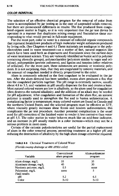
TABLE 8.5 Chemical Treatment of Colored Water
(Florida swamp drainage at 400 APHA color)
Variable
Alum dosage, mg/LAluminate dosage, mg/LNonionic polymer, mg/LPolyamine, mg/LFinal results
PHColor
Conventionalalum program
55400.5
none
5.25-10
Alum-polyamineprogram
3530none
5
6.55-10
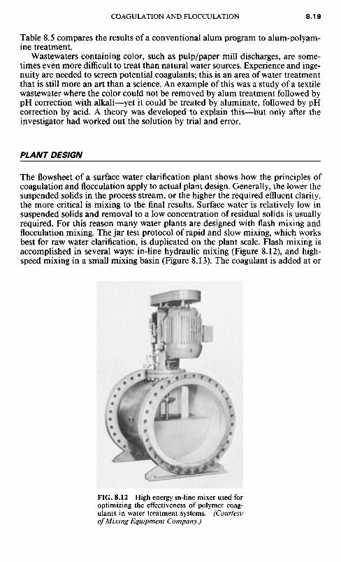
Table 8.5 compares the results of a conventional alum program to alum-polyam-ine treatment.
Wastewaters containing color, such as pulp/paper mill discharges, are some-times even more difficult to treat than natural water sources. Experience and inge-nuity are needed to screen potential coagulants; this is an area of water treatmentthat is still more an art than a science. An example of this was a study of a textilewastewater where the color could not be removed by alum treatment followed bypH correction with alkali—yet it could be treated by aluminate, followed by pHcorrection by acid. A theory was developed to explain this—but only after theinvestigator had worked out the solution by trial and error.
PLANT DESIGN
The flowsheet of a surface water clarification plant shows how the principles ofcoagulation and flocculation apply to actual plant design. Generally, the lower thesuspended solids in the process stream, or the higher the required effluent clarity,the more critical is mixing to the final results. Surface water is relatively low insuspended solids and removal to a low concentration of residual solids is usuallyrequired. For this reason many water plants are designed with flash mixing andflocculation mixing. The jar test protocol of rapid and slow mixing, which worksbest for raw water clarification, is duplicated on the plant scale. Flash mixing isaccomplished in several ways: in-line hydraulic mixing (Figure 8.12), and high-speed mixing in a small mixing basin (Figure 8.13). The coagulant is added at or
FIG. 8.12 High energy in-line mixer used foroptimizing the effectiveness of polymer coag-ulants in water treatment systems. (Courtesyof Mixing Equipment Company.)

FIG. 8.13 Flash mixers are designed to disperse chemicals throughoutthe water instantaneously, prior to flocculation. (Courtesy of FMCCorporation, Material Handling Division.)
FIG. 8.14 Reel-type paddle flocculator in a municipal water treatment plant. (Courtesy ofEnvi-rex, a Rexnord Company.)
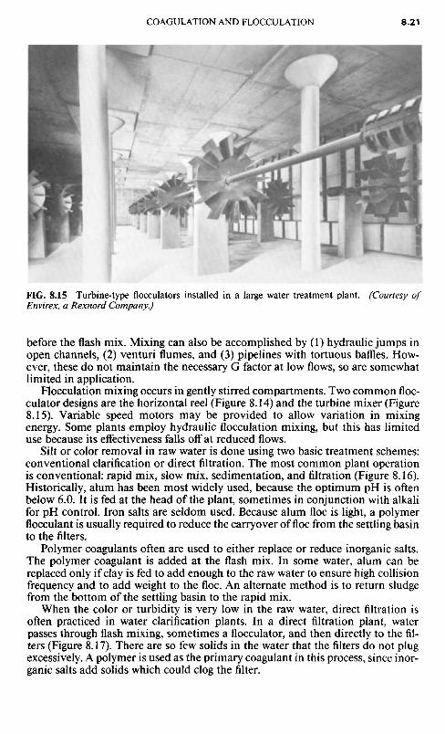
FIG. 8.15 Turbine-type flocculators installed in a large water treatment plant. (Courtesy ofEnvirex, a Rexnord Company.)
before the flash mix. Mixing can also be accomplished by (1) hydraulic jumps inopen channels, (2) venturi flumes, and (3) pipelines with tortuous baffles. How-ever, these do not maintain the necessary G factor at low flows, so are somewhatlimited in application.
Flocculation mixing occurs in gently stirred compartments. Two common floc-culator designs are the horizontal reel (Figure 8.14) and the turbine mixer (Figure8.15). Variable speed motors may be provided to allow variation in mixingenergy. Some plants employ hydraulic flocculation mixing, but this has limiteduse because its effectiveness falls off at reduced flows.
Silt or color removal in raw water is done using two basic treatment schemes:conventional clarification or direct filtration. The most common plant operationis conventional: rapid mix, slow mix, sedimentation, and filtration (Figure 8.16).Historically, alum has been most widely used, because the optimum pH is oftenbelow 6.0. It is fed at the head of the plant, sometimes in conjunction with alkalifor pH control. Iron salts are seldom used. Because alum floe is light, a polymerflocculant is usually required to reduce the carryover of floe from the settling basinto the filters.
Polymer coagulants often are used to either replace or reduce inorganic salts.The polymer coagulant is added at the flash mix. In some water, alum can bereplaced only if clay is fed to add enough to the raw water to ensure high collisionfrequency and to add weight to the floe. An alternate method is to return sludgefrom the bottom of the settling basin to the rapid mix.
When the color or turbidity is very low in the raw water, direct filtration isoften practiced in water clarification plants. In a direct filtration plant, waterpasses through flash mixing, sometimes a flocculator, and then directly to the fil-ters (Figure 8.17). There are so few solids in the water that the filters do not plugexcessively. A polymer is used as the primary coagulant in this process, since inor-ganic salts add solids which could clog the filter.
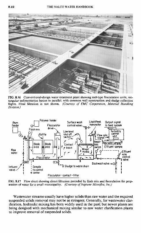
FIG. 8.17 Flow sheet showing direct filtration preceded by flash mix and flocculation for prep-aration of water for a small municipality. (Courtesy of Neptune Microfloc, Inc.)
Wastewater streams usually have higher solids than raw water and the requiredsuspended solids removal may not be as stringent. Generally, for wastewater clar-ification, hydraulic mixing has been widely used in the past; but newer plants arebeing designed with mechanical mixing similar to raw water clarification plantsto improve removal of suspended solids.
FIG. 8.16 Conventional-design water treatment plant showing reel-type flocculation units, rec-tangular sedimentation basins in parallel, with common wall construction and sludge collectionflights. Final filtration is not shown. (Courtesy of FMC Corporation, Material HandlingDivision.)
Influent,valve
Rawwater
Bladearea
Bladearea
Contactbasin
Flocculator
Sampleto controlcenter
Flocculator-contact-fi lter
Sludge to waste drainBackwash valve
Effluentratecontrolvalve
Mixedmedia
Head-lossswitch Effluent sample
Raw water sample
Flow ratesignal
Turbiditycontrolunit
Liquid leveltransmitter
Output signalto feed system
Surface washcontrol valve
Polymer feeder
Flash mixBaffle
Flocculatordrive
Low-levelshut offswitch
Alumfeeder

SUGGESTED READING
AWWA: Water Quality and Treatment, McGraw-Hill, New York, 1971.Water Treatment Handbook, Infilco-Degremont, Inc., Halsted Press, New York, distribu-tors, 1979.
Nordell, Eskel: Water Treatment for Industrial and Other Uses, Reinhold, New York, 1961.Void, M. J., and R. D. VoI,: Colloid Chemistry: The Science of Large Molecules, SmallParticles, and Surfaces, Reinhold, New York, 1964.