design of distributors - ssussu.ac.ir/cms/fileadmin/user_upload/daneshkadaha/dbehdasht/markaz... ·...
TRANSCRIPT

10 Design of distributors
Chapters 6 to 9 have shown how indispensable distributors are in packed columns - fordistributing either the liquid at the head or the gas at the bottom of the column or for redis-tributing the phases at given heights -. Their design is governed by the principle on whichthey operate (cf. Fig. 10.1). It merits great importance because distributors serve to over-come maldistribution, which - according to Eqn (8-25) - may greatly impair the efficiency oflarge-diameter columns. Allowance must be made in design for differences in liquid load,because it is obviously more difficult to distribute small than large amounts of liquid (cf.Table 10.1).
Distributor Principle Design
Capillary
Profiled
slot qpSieve
or
tube
Y///A ' X/////1
^SZ_c3ir
Slot
Liquid transport
by capillary
forces
passage
as liquid jetsCL)
C L
• o
ID
Liquid discharge
as jets
Overflow
as liquid
jets
Nozzle30°-160° Liquid
distributed
as droplets
Per-
forated
Fig. 10.1. The principles of liquid distribution
SOFTbank E-Book Center Tehran, Phone: 66403879,66493070 For Educational Use.

tube or boxperfor. plate or boxprofiled slotcapillary
> 20> 10> 20.05-0.5
230 10 Design of distributors
Table 10.1. Ranges of liquid loads for various distributors and the flow rates per outlet
Liquid load uL [m3/m2h] Type of distributor Liquid per feed point103l [m3/h]
5 - large1 - medium0.5 - very large0.5 - 10
10.1 Fundamental design aspects and relationships
Distributors must be accurately finished and correctly installed to avoid differences inliquid level. They should be fitted with drip edges, which prevent coalescence of the liquidon the underside and thus ensure trouble-free operation.
Capillary plates are suitable distributors for very low liquid loads, viz. uL > 0.5 m3/m2h,and allow flow rates of about 0.05-0.5 1/h through each outlet. Profiled-slot distributors per-mit liquid loads of uL = 0.5-200 m3/m2h, and the flow rate through each outlet is higherthan 2 1/h. Perforated-plate and trough-type distributors with liquid discharge are recom-mended for moderate liquid loads, viz. uL > 1 m3/m2h. The volumetric flow rate / throughan outlet in a trough-type distributor is higher than 10 1/h.
A crucial parameter in the selection or design of a distributor is the liquid load uL
required for the separation process. Together with the head ho (cf. Fig. 10.2), it allows theflow velocity at an outlet uo, and thus the number of outlets required, to be determined indistributors with liquid discharge or overflow. In this case, the usual equation for flowthrough orifices applies, i.e.
uo = yJ2gho (10-1)
Usually, the head ho is higher than 5-10 mm.Since the cross-sectional area a of the outlet is known, the volumetric flow rate / can be
obtained from
1 = auo (10-2)
If the outlets are of the shapes shown in Fig. 10.2, q can be easily determined. Accordingto H. Ulrich, W. Deeke and W. Geipel, the following equations apply for outlets in trough-type distributors:
(1) For filleted rectangular slots:
2I = X — b \[2~g}Q (10-3)
(2) For triangular notches:o
^ = X — yJ2gh$ tan 6 (10-4)
Packed Towers in Processing and Environmental Technology. Reinhard BilletCopyright © 1995 VCH Verlagsgesellschaft mbH, WeinheimISBN: 3-527-28616-0
SOFTbank E-Book Center Tehran, Phone: 66403879,66493070 For Educational Use.

10.1 Fundamental design aspects and relationships 231
-Liquid head
Width of slots
I = Liquid flow rate per feeder
Notch angle
Fig. 10.2. Schematic graph of distributors with outlets for liquid discharge
where Xh the constriction factor (for vena contracta).According to H. Ulrich et al., allowance for the effect of surface tension o on the con-
striction factor X can be made by means of a characteristic value Nz for the number offeeders, which is given by
Nz = —QLg dh hn (10-5)
where QL is the liquid density, a is the surface tension, and dh is the hydraulic diameter,which depends on the outlet's effective cross-sectional area a and wetted periphery P, i.e.
a (10-6)
Values of Nz for open box-type or trough-type distributors can be read off against theconstriction factor in Fig. 10.3.
The flow rate / of liquid through a circular outlet with a diameter d on the lower side of aperforated-plate or trough-type distributor is given by
jt
T gho-QL I
(10-7)
If the outlets have been carefully rounded off, the constriction factor is X = 0.9-1. Theterm Apv allows for the pressure drop in the vapour as it passes through the distributor; it isthe amount by which the pressure at the outlet exceeds the pressure at the surface of theliquid.
SOFTbank E-Book Center Tehran, Phone: 66403879,66493070 For Educational Use.

232 10 Design of distributors
0.6
0.5
><b 0.4
I 0.3
0.2
0.1
1
I1
/1
/
\y
//
Liquid (
/y
/
Dutlet slots
//
/
^̂
y
0.4 0.8 1.2 1.6 2 2.4 2.8 3.2
Characteristic for No. of outlets Nz
3.6
Fig. 10.3. Diagram for the determination of the constriction factor for the outlets in distributors ofthe type shown in Fig. 10.2
Experiments have shown that all the outlets in distributors with liquid overflow will bereliably fed if the feeder characteristic, as defined by Eqn (10-5), is Nz > 2. This figure cor-responds to a liquid flow rate of / = ca. 0.01 m3/h per slot in trough-type distributors withrectangular slots of 5-mm width; and of / = ca. 0.005 m3/h per notch, in those with tri-angular notches.
Once / is known, the number Z of distributor outlets per square metre of column cross-section that is required to cope with a liquid load uL in m3/m2h can be obtained from
z < I(10-8)
Liquid distributors that operate on the principles outlined in Fig. 10.2 can be quite easilydesigned with the aid of Eqns (10-3) to (10-8) and Fig. 10.3. Deviations from the tolerancesspecified in manufacture and assembly are responsible for differences in the head ho andflow rate /. Consequently, it would be an advantage to instal some means of adjustment inthe components of a distributor. For instance, differences in head of Aho = 1 mm betweenthe lowermost and uppermost ends of the distributor would lead to maldistribution of about10%, i.e. M = 0.1, or more depending on the design. It is evident from Eqns (8-25) and(8-28) that the associated reduction in column efficiency Ec represents the borderline casethat can be barely disregarded. However, as can be easily proved, differences in head ofAho = 4 mm simply cannot be tolerated.
Experiments with the various types of distributors illustrated in Fig. 10.2 have verifiedthe relationships expressed in Eqns (10-4) to (10-7) and Fig. 10.3. The breadth b of the slotswas varied between 4 and 6 mm, the notch angle 2 6 was 90°, and the head was variedbetween 20 and 40 mm.
SOFTbank E-Book Center Tehran, Phone: 66403879,66493070 For Educational Use.

10.2 Types of phase distributors 233
Obviously, uniform distribution can be achieved more easily at high rather than at lowliquid flow rates. Thus, if the liquid load is uL ~ 1 m3/m2h and the head is ho = 1 mm, thenumber of liquid outlets Z required per square metre of column cross-section would beZ = 150 in a plate distributor with perforations of d = 3 mm diameter. In the same columnoperating at the same load but under a head of ho = 3 mm, the number required would beZ = 80. If the column were fitted with a profiled-slot distributor, the number of outletsrequired would be Z = 200/m2. At such low loads, capillary-plate distributors would accountfor the highest number of outlets.
Plates with spouts or trough-type distributors with liquid overflow that permit flow ratesof 20 1/h per outlet are suitable for liquid loads ranging from uL = 5 m3/m2h to very highvalues.
It is general practice to predistribute the liquid in the designs described above. By thismeans, perfect hydrodynamic functioning of the distributor itself and thus optimum liquiddistribution over the column cross-section can be ensured.
Predistribution is unnecessary in pipe distributors, in which the liquid is discharged eitherthrough perforations or by nozzles. These distributors are suitable for liquid loads rangingfrom low to very high.
Distributors consisting simply of spray nozzles fitted above the bed obviously have a com-paratively restricted operating range in which the sprays can be uniformly distributed overthe column cross-section.
10.2 Types of phase distributors
There are numerous designs of phase distributors. The few that have been selected fordiscussion here are characteristic of those used in industrial-scale columns.
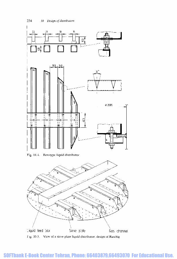
The trough-type distributors shown in Fig. 10.4 are suitable for average to high liquidloads in columns of 0.6 m diameter or larger. If the liquid loads are small, bolts should beinstalled to allow alignment of the individual troughs.
If the liquid load is less than 5 m3/m2h, perforated plates (cf. Fig. 10.5) or distributorswith spouts (cf. Chapter 3) are recommended.
Perforated-pipe distributors (cf. Fig. 10.6) still give satisfactory performance at liquidloads of 0.75 m3/m2h in columns of any given diameter. If they are properly designed, theyalso allow very low liquid loads of about 25 m3/m2h to be uniformly distributed. The sameapplies to distributors consisting of spray nozzles, but these are not depicted here.
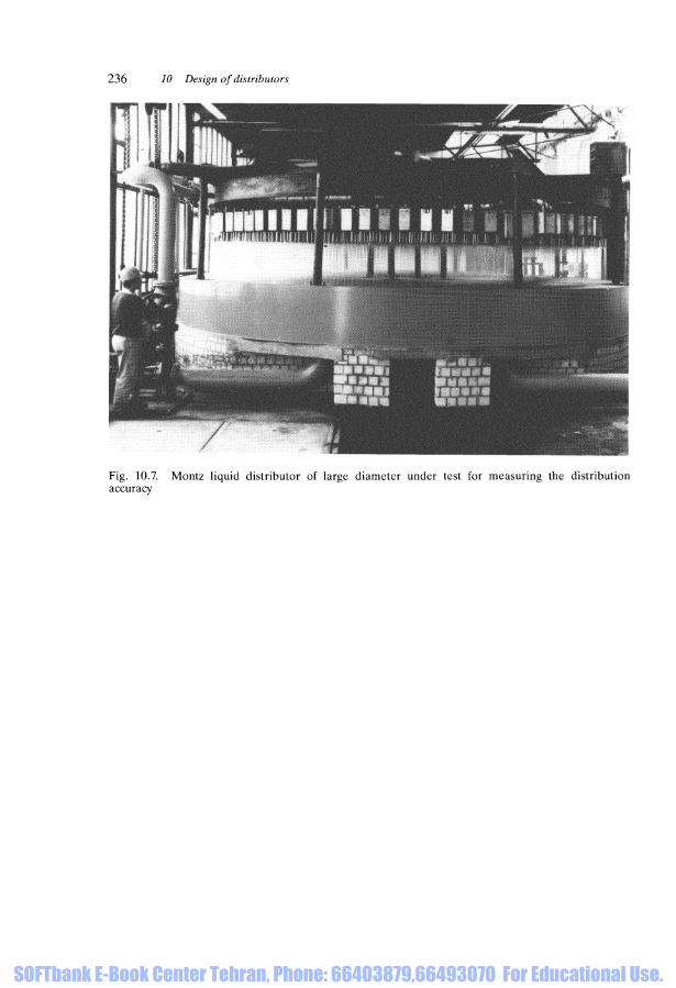
Before they are installed, liquid distributors for columns of very large diameter should besubjected to experiments on a test rig in order to determine the standard deviation in liquiddistribution (cf. Fig. 10.7).
Devices for liquid redistribution are advisable in many separation tasks. An integratedstructure consisting of support plates, liquid collectors, and phase distributors (i.e. for theliquid and gas phases) can be used for this purpose (Fig. 10.8).
The dimensions entered in Fig. 10.9 are useful for arranging distribution within a column.Other column fittings, e.g. support plates, packing retainers, and liquid collectors for
product withdrawal are shown schematically in Fig. 10.10.
SOFTbank E-Book Center Tehran, Phone: 66403879,66493070 For Educational Use.
234 10 Design of distributors
22
—i i
21 18 15
- 1 1 - I 1
1
0611
•160 140
30°
VT7
-H+l
at-
lil
Fig. 10.4. Box-type liquid distributor
0 2600
Liquid feed box Sieve plate Gas channelFig. 10.5. View of a sieve plate liquid distributor, design of Raschig
SOFTbank E-Book Center Tehran, Phone: 66403879,66493070 For Educational Use.

10.2 Types of phase distributors 235
Fig. 10.6. Pipe-type liquid distributor
SOFTbank E-Book Center Tehran, Phone: 66403879,66493070 For Educational Use.
236 10 Design of distributors
Fig. 10.7. Montz liquid distributor of large diameter under test for measuring the distributionaccuracy
SOFTbank E-Book Center Tehran, Phone: 66403879,66493070 For Educational Use.

12
0-2
70
-
Fig.
10.
8.
Dra
win
g of
a r
edis
trib
utor
for
bot
h liq
uid
and
gas
phas
es,
incl
udin
g su
ppor
t tra
y an
d liq
uid
colle
ctor
Fig.
10.
9.
Cha
ract
eris
tic d
imen
sion
s fo
rth
e ar
rang
emen
t of
pha
se d
istr
ibut
ors
SOFTbank E-Book Center Tehran, Phone: 66403879,66493070 For Educational Use.

238 10 Design of distributors
Vapour
Liquid distributor-
Cover plate
Packing
Support tray
Liquid collector
Distributor
Cover plate
Packing
Redistributor
Packing
Support tray
Reflux
nnnn
^Vapour
Fig. 10.10. Schematic diagram indicating the location of internals for packed towers
SOFTbank E-Book Center Tehran, Phone: 66403879,66493070 For Educational Use.