unit-1(comp)
TRANSCRIPT
8/4/2019 Unit-1(comp)
http://slidepdf.com/reader/full/unit-1comp 1/44
Unit -1 Introduction & Behavioral Moeling:
Topics to be covered in this unit:
Introduction to HDLs: Difference between HDL and other software languages, Overview of Digital
System esign using HDL.Basic VHDL language Elements: Identifiers Data Objects, scalar & composite Data Types, Operators.Behavioral Modeling with example: Entity Declaration, Architecture Body, Process Statement andsequential statements, Inertial & transport delay models, creating signal waveforms, signal drivers, effectof inertial & transport delay on signal drivers.
1.1 Introduction to HDLs:
1.1.1: Difference Between HDL and Other Software Languages: VHDL was developed toaddress a number of recurrent problems in the development, exchange and documentationof digital hardware. For instance, a typical delivery of hardware to the government wouldinclude tens of thousands of pages of documentation that needed to be shifted through
during acceptance and testing and referred to throughout the maintenance life of thecomponent. When the component needed to be replaced it took a large amount of effortto reconstruct the intended behavior of the component. A good hardware descriptionlanguage solves this problem because the documentation is executable and all elementsare tied into a single model.
While there are many hardware description languages, there was, prior to VHDL,no accepted standard in the industry. Many of the existing languages are developed toserve the simulators that run them, and are often proprietary developments of particular companies. Others target a particular technology, design level, or design methodology.VHDL is technology independent, is not tied to a particular simulator or value set, anddoes not enforce a design methodology on a designer. What it does do is allow the
designer the freedom to choose technologies and methodologies while remaining within asingle language. No one can foresee the changes that will take place in digital hardwaretechnology in the future. Therefore, VHDL provides abstraction capabilities that facilitatethe insertion of new technologies into existing designs.
VHDL thus offers a number of benefits over other hardware descriptionlanguages.1.1.1.1 Public Availability: VHDL was developed under a Government contract and isnow an IEEE standard. The Government has a strong interest in maintaining VHDL as a public standard. The advantages of this status are apparent; without it, many of the other benefits described below would not exist.
1.1.1.2 Design Methodology and Design Technology Support: VHDL was designed tosupport many different design methodologies (e.g., top-down versus library-based) anddesign technologies (e.g. synchronous versus asynchronous, or PLA versus randomlogic). In this way, the language manages to provide design assistance to organizationsthat operate in very different ways, and that have very different design needs. VHDL isappropriate for use by a CAD/CAE house that sells library-based design tools, and isequally appropriate for an aerospace company that does a large amount of ASIC design.
8/4/2019 Unit-1(comp)
http://slidepdf.com/reader/full/unit-1comp 2/44
1.1.1.3 Technology and Process Independence: VHDL was designed to be independentof both technology and process. By this we mean that VHDL does not have embeddedwithin it an understanding of particular technologies or processes. However, suchinformation can be written using VHDL. Thus, a working (i.e., simulatable) descriptionof a system may developed above the gate level, and then, decompose into gate level
implementation depending on the chosen implementation technology (e.g. CMOS,nMOS, GaAs). The advantages of this capability for second sourcing are apparent.
1.1.1.4 Wide Range of Descriptive capability: VHDL supports behavioral descriptionof hardware from the digital system (e.g., box) level to the gate level. One of the primaryadvantages of VHDL lies in the ability to capture the operation of a digital system on anumber of these descriptive levels at once, using a coherent syntax and semantics acrossthese levels, and to simulate that system using any mixture of those levels of description.It is therefore possible to simulate designs that mix high-level behavioral descriptions of some subsystems with detailed implementations of other subsystems in the model.
This facilitates the development of a design that correctly reflects the intention of the original specification of the system. During maintenance of the system, redesigns or alternations to the system can be verified by replacing the VHDL in the description andresimulating with the test set.
Many existing hardware description languages operate best at the logic and gatelevel; for this reason, hardware designers may be most familiar with the use of HDL’s nosupport low-level logic design. While VHDL is perfectly suited to this level of description, it extends well beyond that level. Therefore, the larger examples in this book have been purposely chosen to show VHDL in contexts beyond the logic level of digitalhardware.
1.1.1.5 Design Exchange: VHDL is standard and, as a result, VHDL models areguaranteed to run on any system that conforms to that standard. This means that modelsdeveloped at one location will run at other locations (and produce the same simulationresults) whether or not both locations use the same VHDL tool sets. This has manyimplications for the use of VHDL. As VHDL models of common components becomeavailable, designers will simulate their design with those model descriptions. In this waydesigners can try a number of different components and choose those that best fit theconstraints and requirements of the system being designed.
Another aspect of this capability is that teams can exchange high-leveldescriptions of the subsystems of a digital system, which then allows each subsystem to be developed independent of progress on the other subsystems.
For example, suppose an organization was developing a digital system andwanted to contract out a subsystem to another organization. The contracting organizationcould develop a high level VHDL description of the system with the subsystems brokenout into design entities. The high level description would then be given to the contractor for development. The contractor could develop the subsystem in VHDL while all alonghaving a simulatable description of the rest of the system. The contracting organizationwould also be able to develop its portion of the system and test without waiting for the

8/4/2019 Unit-1(comp)
http://slidepdf.com/reader/full/unit-1comp 3/44
subsystem to be developed. This greatly reduces the integration effort and reduces thetime of the entire development significantly.
1.1.1.6 Large Scale Design and Design Reuse: VHDL was modeled on a philosophysimilar to that of many modem programming languages- that design decomposition aids
are just as important as detailed descriptive capabilities when it comes to supporting thedevelopment of large designs being executed by multi-person teams. There are severalelements of the language specifically targeted at this goal. Packages, configurationdeclarations, and the concept of multiple bodies exhibiting different implementation of anentity are all present in the language to support design sharing, experimentation, anddesign management.
These elements of the language also tend to support design re-use, since they promote the encapsulation of design information and the ability to be flexible inconforming to others’ design conventions when using an already designed part.
1.1.1.7 Government Support: The VHSIC Program Office developed VHDL with a
clear vision of how it itself wanted to use VHDL. VHDL can be used throughout the lifecycle of a digital system, and is likely to become a major component of the procurement process. The Department of Defense is currently requiring VHDL descriptions on allcontracts that develop ASIC’s.
1.1.2 Overview of Digital System Design Using HDL: VHDL is a acronym which standsfor VHSIC (Very High Speed Integrated Circuit) Hardware Description Language.VHDL language can be regarded as an integrated amalgamation of the followinglanguages:Sequential Language, Concurrent language, net-list language, timing specification, &wave generation language.
VHDL is case insensitive i.e. upper case letters are equivalent to lower case letters.Statements are terminated in VHDL with a semicolon. That means as many line breaks or other constructs as wanted can be inserted or left out. Only the semicolons are considered by the VHDL compiler. Lists are normally separated by commas. Signal assignments arenotated with the composite assignment operator’<=’.VHDL is used for documentation, verification & synthesis of large digital design. VHDLcan be used to take three different approaches for describing hardware. These threedifferent approaches are the structural, behavioral & dataflow models of hardwaredescription. VHDL is a standard (VHDL – 1076) developed by IEEE (Institute of Electrical & Electronics Engineers). Currently the most widely used version is the 1987(Std. 1076-1987) version which is sometimes referred to as VHDL’87 or VHDL. There is
also a newer version of language called VHDL’93.VHDL is a hardware description language that can be used to model a digital
system at many levels of abstraction, ranging from the algorithmic level to the gate level.VHDL has constructs that enables to express the concurrent or sequential behavior of adigital system with or without timing. VHDL also allows to model the system asinterconnections of components. Models written in VHDL can be verified using VHDLsimulator.
8/4/2019 Unit-1(comp)
http://slidepdf.com/reader/full/unit-1comp 4/44
VHDL provides high level language constructs that enables designers to describe largecircuits. VHDL provides portability of codes between synthesis & simulation tools.The major capabilities of VHDL are:
1.1.2.1 Power & Flexibility: VHDL has powerful language constructs with which to
write succinct code descriptions of complex control logics. It supports design libraries &creation of reusable components. It provides for design hierarchies to create modular designs. It is one language for design & simulation. It has multiple level of designdescription for controlling design implementation i.e. top-down, bottom-up or mixed.
• Top-Down Approach: In this approach, firstly the top level behavior is designed& then it is partitioned into smaller subsystems & then it is reduced to simplecomponents suitable for large designs.
• Bottom-Up Approach: It is used when a library of known low level component isavailable. We build medium subsystems from them & then finally interconnectthem to realize the overall system. This approach is suitable for small systemsusing standard components.
• Mixed Approach: In this approach, one starts from top level but does not go rightupto the component level. One can stop when finds suitable medium level entitiesfor realizing the design.
1.1.2.2 Device Independent Design: VHDL permits to create a design without having afirst choose a design for implementation. With one design description one can targetmany design architectures. VHDL also permits multiple style of design descriptions.
1.1.2.3 Portability: VHDL is a standard, design descriptions can be taken from onesimulator to another, one synthesis tool to another, & one platform to another i.e. VHDLdesign descriptions can be used in multiple projects.
1.2 Basic VHDL Language Elements:
1.2.1 Identifiers: Identifiers can be defined as the identification of any data type. InVHDL identifiers are used as reserved words and as programmer defined names.Identifiers are simple names starting with a letter and may have letters and digits. Self defined identifier as defined by the VHDL 87 standard may contain letters, numbers andunderscores and must begin with a letter. In VHDL there two types of identifiers:Basic IdentifiersExtended Identifiers
1.2.1.1 Basic Identifier:Basic Identifier as defined by the VHDL 87 standard may contain following:
• Must begin with alphabetic characters (a-z or A-Z)
• Can contain alphanumeric (a-z, A-Z, 0-9) or underscore (_) characters
• Can be up to 1024 characters long
• Case insensitive
• No two consecutive underscores
8/4/2019 Unit-1(comp)
http://slidepdf.com/reader/full/unit-1comp 5/44
• Cannot contain white space
• No VHDL keyword
ExamplesmySignal_23 --Valid --Basic Identifier
RDY, rdy, Rdy --Valid --Identical Identifier Vector_&_vector --Invalid --special Identifier Last of Zout --Invalid --White spacesIdle__state --Invalid --consecutive underscores24ma_signal --Invalid --Begins with a numeralopen, register --Invalid --VHDL keywords
1.2.1.2 Extended Identifier:
Extended Identifier as defined by the VHDL 93 standard may contain following:
• Enclosed in back slashes
• Case sensitive• Graphical characters allowed
• May contain spaces and consecutive underscores
• VHDL keywords allowed
Examples\mySignal_23\ --Valid --Basic Identifier \RDY\,\ rdy\,\ Rdy\ --Valid --Identical Identifier \Vector_&_vector\ --Valid --special Identifier \Last of Zout\ --Valid --White spaces\Idle__state\ --Valid --consecutive underscores
\24ma_signal\ --Valid --Begins with a numeral\open\,\register\ --Valid --VHDL keywords\AL\\LU\ --Valid --Represents ALLU
1.2.2 Data Objects: For holding a value of a specified type, we are required Data Object.A VHDL data object belongs to one of the following classes:
1.2.2.1 Constants
A constant associates a value to a symbol of a given data type. The use of constants mayimprove the readability of VHDL code and reduce the likelihood of making errors. Thedeclaration syntax is:
constant symbol: type := value;Examples constant Vcc: signal:= '1'; --logic 1 constant constant zero4: bit_vector(0 to 3) := ('0','0','0','0');
constant Vcc: integer; --deffered constant
8/4/2019 Unit-1(comp)
http://slidepdf.com/reader/full/unit-1comp 6/44
Numeric Constants: Numeric constants can be defined, and can be of any base(default is decimal). Numbers may include embedded underscores to improvereadability.
Format: base#digits# -- base must be a decimal number Examples
16#9FBA# (hexadecimal)2#1111_1101_1011# (binary)16#F.1F#E+2 (floating-point, exponent is decimal)= (F.1F)16 (16)2
Bit String Literals: Bit vector constants are specified as literal strings.Examples
X"FFE" (12-bit hexadecimal value)o"777" (9-bit octal value)b"1111_1101_1101" (12-bit binary value)
1.2.2.2 Variables
A variable is declared within a blocks, process, procedure, or function, and is updatedimmediately when an assignment statement is executed. A variable can be of any scalar or aggregate data type, and is utilized primarily in behavioral descriptions. It canoptionally be assigned initial values (done only once prior to simulation). The declarationsyntax is:variable symbol: type [:= initial_value];Examples
processvariable count: integer := 0;variable rega: bit_vector(7 downto 0);
begin...count := 7; -- assign values to variablesrega := x"01";...
end;
1.2.2.3 Signals
A signal is an object with a history of values (related to "event" times, i.e. times at whichthe signal value changes).Signals are declared via signal declaration statements or entity port definitions, and may
be of any data type. The declaration syntax is:signal sig_name: data_type [:=initial_value];Examples
signal clock: bit;signal GND: bit := '0';signal databus: std_ulogic_vector(15 downto 0);signal addrbus: std_logic_vector(0 to 31);
8/4/2019 Unit-1(comp)
http://slidepdf.com/reader/full/unit-1comp 7/44
1.2.2.4 File
A file is an object which contains a sequence of values which can be read or written tothe file using read & write procedures.Files are declared via file declaration statements. The declaration syntax is:
file file_name: file_type [[ open mode] is str_exp];
str_exp is interpreted by the host environment as the physical name of file. File can beopened in Read only, Write only and Append mode.
Examplefile maths: text open Read_mode;
1.2.3 Data Type:
In VHDL, signals must have a data type associated with them that limits the number of possible values. Data types allowed in VHDL consists of everything from scalar numeric
types to composite arrays and records to file types. Each VHDL objects must beclassified as being of a specific data type. VHDL includes a number of predefined datatypes, and allows users to define custom data types as needed. This type has to be fixedwhen the signal is declared, either as entity port or an internal architecture signal, andcannot be changed during runtime. Whenever signal values are updated, the data types on both sides of the assignment operator ‘<=’ have to match.
Predefined Scalar Data Types (single objects)
VHDL Standard:
•
bit values: '0', '1'• boolean values: TRUE, FALSE• integer values: -(231) to +(231 - 1) {SUN Limit}• natural values: 0 to integer'high (subtype of integer)• positive values: 1 to integer'high (subtype of integer)• character values: ASCII characters (eg. 'A')• time values include units (eg. 10ns, 20us)
A number of data types are already defined in the standard package which is alwaysimplicitly referenced ‘Boolean’ is usually used to control the flow of the VHDLexecution while ‘bit’ uses level values (‘0’,’1’) instead of truth values (‘false’,’true’) andis therefore better suited to model wires. Number values can be communicated via signalsof type ‘integer’ or ‘real’. The actual range and accuracy depends on the platformimplementation and only lower bounds are defined, e.g. integers are guaranted to be atleast 32 bits wide. Floating point operations can not be synthesized automatically, yet, i.e.the use of ‘real’ data types is restricted to test bench applications. The same applies to‘character’ and ‘time’. Time is a special type as it consists out of a numerical value and a physical unit. It is used to delay the execution of statement for a certain amount of time,e.g. in test benches or to model gate and propagation delays. Signals of data types ‘time’

8/4/2019 Unit-1(comp)
http://slidepdf.com/reader/full/unit-1comp 8/44
can be multiplied or divided by ‘integer’ and ‘real’ values. The result of these operationsremains of data type ‘time’. The internal resolution of VHDL simulators is set to femtoseconds (fs).
IEEE Standard 1164 (package ieee.std_logic_1164.all)
std_ulogic values: 'U','X','1','0','Z','W','H','L','-'
‘U’ = uninitialized
‘X’ = unknown
'W' = weak 'X'
'Z' = floating
'H'/'L' = weak '1'/'0'
'-' = don't care
• std_logic resolved "std_ulogic" values• X01 subtype {'X','0','1'} of std_ulogic• X01Z subtype {'X','0','1','Z'} of std_ulogic• UX01 subtype {'U','X','0','1'} of std_ulogic• UX01Z subtype {'U','X','0','1','Z'} of std_ulogic
Subtype is a type with a constraint.
Data types are classified into four categories.
1. Scalar types2. Composite types3. Access types4. File types
1.2.3.1 Scalar types
Scalar types have exactly one value. Scalar types do not have distinguishable elements.
Scalar types encompass these four classes of types.
a) Integer types b) Physical typesc) Floating typesd) Enumerated types
8/4/2019 Unit-1(comp)
http://slidepdf.com/reader/full/unit-1comp 9/44
Integer, physical and floating types are classified as numeric types, as the valuesassociated with these types are numeric.
1.2.3.1.1 Integer Types
An integer type is a range of integer values within a specified range. The syntax for
specifying integer types is:
integer_type_definition ::= range_constraintrange_constraint ::= range rangerange ::= simple_expression direction simple_expressiondirection ::= to | downto
The expressions that specify the range must of course evaluate to integer numbers. Typesdeclared with the keyword to are called ascending ranges, and those declared with thekeyword downto are called descending ranges.
The VHDL standard allows an implementation to restrict the range, but requires that itmust at least allow the range –2147483647 to +2147483647. Some examples of integer type declarations:
type byte_int is range 0 to 255;type signed_word_int is range –32768 to 32767;type bit_index is range 31 downto 0;
There is a predefined integer type called integer . The range of this type is implementationdefined, though it is guaranteed to include –2147483647 to +2147483647.
Values belonging to integer type are called integer literal.
1.2.3.1.2 Physical Types:
A physical type is a numeric type for representing some physical quantity, such as mass,length, time or voltage. The declaration of a physical type includes the specification of a base unit, and possibly a number of secondary units, being multiples of the base unit. Thesyntax for declaring physical types is:
physical_type_definition ::= range_constraint units
base_unit_declaration { secondary_unit_declaration }end units
base_unit_declaration ::= identifier ;secondary_unit_declaration ::= identifier = physical_literal ; physical_literal ::= [ abstract_literal ] unit _name
Some examples of physical type declarations:(a) type length is range 0 to 1E9
units

8/4/2019 Unit-1(comp)
http://slidepdf.com/reader/full/unit-1comp 10/44
um;mm = 1000 um;cm = 10 mm;m = 1000 mm;in = 25.4 mm;
ft = 12 in;yd = 3 ft;rod = 198 in;chain = 22 yd;furlong = 10 chain;
end units;
(b) type resistance is range 0 to 1E8units
ohms;kohms = 1000 ohms;
Mohms = 1E6 ohms;end units;
The predefined physical type time is important in VHDL, as it is used extensively tospecify delays in simulations. Its definition is:
(c) type time is range implementation_definedunits
fs;ps = 1000 fs;ns = 1000 ps;us = 1000 ns;ms = 1000 us;sec = 1000 ms;min = 60 sec;hr = 60 min;
end units;
To write a value of some physical type, you write the number followed by the unit. For Example:10 mm, 1200 ohm, 23 ns
1.2.3.1.3 Floating Point Types
A floating point type is a discrete approximation to the set of real numbers in a specifiedrange. The precision of the approximation is not defined by the VHDL languagestandard, but must be at least six decimal digits. The range must include at least –1E38 to+1E38. A floating point type is declared using the syntax:
floating_type_definition := range_constraint
8/4/2019 Unit-1(comp)
http://slidepdf.com/reader/full/unit-1comp 11/44
Some examples are:
type signal_level is range –10.00 to +10.00;type probability is range 0.0 to 1.0;
There is a predefined floating point type called real. The range of this type isimplementation defined, though it is guaranteed to include –1E38 to +1E38.
1.2.3.1.4 Enumeration Types
An enumeration type is an ordered set of identifiers or characters. The identifiers andcharacters within a single enumeration type must be distinct, however they may be reusedin several different enumeration types.The syntax for declaring an enumeration type is:
enumeration_type_definition ::= ( enumeration_literal { , enumeration_literal } )
enumeration_literal ::= identifier | character_literal
Examples:type logic_level is (unknown, low, undriven, high);type alu_function is (disable, pass, add, subtract, multiply, divide);type octal_digit is ('0', '1', '2', '3', '4', '5', '6', '7');
There are a number of predefined enumeration types, defined as follows:
type severity_level is (note, warning, error, failure);type boolean is (false, true);type bit is ('0', '1');type character is(NUL, SOH, STX, ETX, EOT, ENQ, ACK, BEL,BS, HT, LF, VT, FF, CR, SO, SI,DLE, DC1, DC2, DC3, DC4, NAK, SYN, ETB,CAN, EM, SUB, ESC, FSP, GSP, RSP, USP,' ', '!', '"', '#', '$', '%', '&', ''','(', ')', '*', '+', ',', '-', '.', '/','0', '1', '2', '3', '4', '5', '6', '7','8', '9', ':', ';', '<', '=', '>', '?','@', 'A', 'B', 'C', 'D', 'E', 'F', 'G','H', 'I', 'J', 'K', 'L', 'M', 'N', 'O','P', 'Q', 'R', 'S', 'T', 'U', 'V', 'W','X', 'Y', 'Z', '[', '\', ']', '^', '_','`', 'a', 'b', 'c', 'd', 'e', 'f', 'g','h', 'i', 'j', 'k', 'l', 'm', 'n', 'o','p', 'q', 'r', 's', 't', 'u', 'v', 'w','x', 'y', 'z', '{', '|', '}', '~', DEL);

8/4/2019 Unit-1(comp)
http://slidepdf.com/reader/full/unit-1comp 12/44
Note that type character is an example of an enumeration type containing a mixture of identifiers and characters. Also, the characters '0' and '1' are members of both bit andcharacter. Where '0' or '1' occurs in a program, the context will be used to determinewhich type is being used.
1.2.3.2 Composite types
Composite types usually hold a collection of values. It is classified into two class.a) Array b) Record
This collection is called an array if all values are of the same type and called a record if all values are of different types. Composite type can be of scalar type, access type or composite type itself.
1.2.3.2.1 Arrays
An array in VHDL is an indexed collection of elements all of the same type. Arrays may be one-dimensional (with one index) or multidimensional (with a number of indices). Inaddition, an array type may be constrained, in which the bounds for an index areestablished when the type is defined, or unconstrained, in which the bounds areestablished subsequently. Example:
Type V_I is array (0 to 10) of BIT;
OR
Type V_I is array (10 to 0) of BIT;
In the above two examples, V_I is an array of 11 elements indexed from 0 to 10 of thetype BIT. Both the examples are same except that the elements are indexed in ascendingand descending order in first and second example respectively. Once we have defined anarray type, we can define objects of that type, including constant, variable and signals.Example:
Type V_I is array (0 to 10) of BIT;
variable VI_I: V_I;
VI_I is a variable of type V_I. Elements of an array can be accessed by specifying their index value. For example, VI_I(4) refers to the third element of VI_I array object.In VHDL, we can define multidimensional arrays
Example:Type V_I is array (0 to 10, 0 to 10) of BIT;
In the above examples, the array range i.e. number of elements in the array, are specifiedexplicitly. They are known as constrained array declarations. Unconstrained array typesare the array types in which the array range is not specified in the type declaration. Thenumber of elements in the array is specified in the object declaration or in the subtypedeclaration.
8/4/2019 Unit-1(comp)
http://slidepdf.com/reader/full/unit-1comp 13/44
Example:
Type V_I is array (Integer range <>) of BIT; -- <> is called as box
variable VI_I1: V_I (-127 to 127);
In this example, V_I is an unconstrained type array in which the index of the array is
specified as an integer type. The element type of V_I is BIT i.e. V_I is an array whichcontains elements of the range from lowest value of integer type (Integer’Low) to highestvalue of integer type (Integer’High) and each element is of type BIT.
1.2.3.2.2 Records
Records in VHDL comprises of named elements of possibly different types. Eachelement name is unique within the record. This name is used to select the element fromthe record value. Records provide abstract modeling capability. The syntax for declaringrecord types is:record_type_definition ::= record element_declaration { element_declaration }
end recordelement_declaration ::= identifier_list : element_subtype_definition ;identifier_list ::= identifier { , identifier )element_subtype_definition ::= subtype_indication
Example:
Type V_I is
Record
N1 : Integer;
N2 : Time;
N3 : Real;
End record;
variable V1: V_I ;
V1:= (22, 10ns, 1.0);
In the above example, type V_I is a record type. Variable V1 is record object. The secondstatement implies that 22 is assigned to N1, 10ns to N2 and 1.0 to N3. Values can beassigned from one record object to another record object of the same type using a singleassignment statement.Example:
signal V2: V_I ;
V2 <= V1;
In the above example, each value of V2 is assigned to V1. We can also assign value toany element of the record individually by using element name.Example:
V1.N1 := 22;
OR

8/4/2019 Unit-1(comp)
http://slidepdf.com/reader/full/unit-1comp 14/44
V3 := V1.N1;
1.2.3.3 Access types
Access types provide very powerful programming language type operations. An accesstype in VHDL is very similar to a pointer in a language like Pascal or C. It is an address,
or a handle, to a specific object. Access types provides access to other objects andcomparable with pointers. Example of access type declaration is: Example:
Type V_I is array (0 to 10) of BIT;
Type VI_I is access V_I ;
In the above example, VI_I is an access type whose values are addresses that point toobjects of type V_I. Access type may have value null which means that it does not pointto any object. The most common operation using an access type is creating andmaintaining a linked list. Only variables can be declared as access types.Example:
Variable V1: VI_I;
In this example, the default value of the variable V1 is NULL. By the nature of accesstypes, they can only be used in sequential processing. Access types are currently notsynthesizable because they are usually used to model the behavior of dynamically sizedstructures such as a linked list.When an object is declared to be of an access type, two predefined functions areautomatically available to manipulate the object. The functions are named NEW andDEALLOCATE.Functions NEW allocate memory of the size of the object in bytes and return the accessvalue. Function DEALLOCATE takes in the access value and returns the memory back
to the system. Example:
V1 : NEW V_I;
DEALLOCATE V1;
In the first statement, keyword NEW causes an object of type V_I to be created and the pointer to this object is returned. In the second statement, keyword DEALLOCATEcauses the storage occupied by the object to which V1 points, to be deallocated, and V1 isset to NULL. Initial values can be assigned to a newly created object by explicitlyspecifying the values. Example:
V1 : NEW V_I (22, 10ns, 1.0);
Access types are very powerful tools for modeling complex and abstract types of systems. Access types bring programming language types of operations to VHDL processes.
1.2.3.4 File types
8/4/2019 Unit-1(comp)
http://slidepdf.com/reader/full/unit-1comp 15/44
File type provides access to other objects and it is used to read or store data in a file. Afile type allows declarations of objects that have a type FILE. A file object type isactually a subset of the variable object type. A variable object can be assigned with avariable assignment statement, while a file object cannot be assigned. A file object can beread from, written to, and checked for end of file only with special procedures and
functions.Files consist of sequential streams of a particular type. A file whose base object type isINTEGER consists of a sequential stream of integers.A file whose object type is a complex record type consists of a sequential stream of complex records. At the end of the stream of data is an end of file mark. Two proceduresand one function allow operations on file objects.Example:type identifier is file of type_mark ; type my_text is file of string ; type word_file is file of word ; file output : my_text;
file_open(output, "my.txt", write_mode);write(output, "some text"&lf);file_close(output);
file test_data : word_file;file_open(test_data, "test1.dat", read_mode);read(test_data, word_value);
1.2.3.5 Predefined VHDL Aggregate Data Types
• bit_vector array (natural range <>) of bit• string array (natural range <>) of char • text file of "string"
1.2.3.6 IEEE Standard 1164 Aggregate Data Types
(From package: ieee.std_logic_1164.all)
• std_ulogic_vector array (natural range <>) of std_ulogic• std_logic_vector array (natural range <>) of std_logic
1.2.3.7 User-Defined Enumeration Types
An enumerated data type can be created by explicitly listing all possible values.
Example
type opcodes is (add, sub, jump, call); -- Type with 4 valuessignal instruc: opcodes; -- Signal of this type...
if instruc = add then -- test for value 'add'
8/4/2019 Unit-1(comp)
http://slidepdf.com/reader/full/unit-1comp 16/44
1.2.3.8 Other user-defined types
Custom data types can include arrays, constrained and unconstrained, and recordstructures.
• Constrained array: Upper and lower indexes are specified.
Example
type word is array (0 to 15) of bit;
• Unconstrained array: Indexes are specified when a signal or variable of thattype is declared.
Examples
type memory is array (integer range <>) of bit_vector(0 to 7);-- a type which is an arbitrary-sized array of 8-bit vectors
variable memory256: memory(0 to 255); -- a 256-byte memory arrayvariable stack: memory(15 downto 0); -- a 16-byte memory array
• Subtypes: A selected subset of values of a given type. Elements of differentsubtypes having the same base type may be combined in expressions (elements of different types cannot). Subtypes can be used to detect out-of-range values duringsimulation. The use of a subtype allows the values taken on by an object to berestricted or constrained subset of some base type. The syntax for declaring asubtype is:
subtype_declaration ::= subtype identifier is subtype_indication ;
subtype_indication ::= [ resolution_function_ name ] type_mark [ constraint ]type_mark ::= type_ name | subtype_ nameconstraint ::= range_constraint | index_constraint
There are two cases of subtypes. Firstly a subtype may constrain values from ascalar type to be within a specified range (a range constraint).
Example:subtype pin_count is integer range 0 to 400;subtype digits is character range '0' to '9';
Secondly, a subtype may constrain an otherwise unconstrained array type by specifying bounds for the indices. For example:
subtype id is string(1 to 20);subtype word is bit_vector(31 downto 0);
There are two predefined numeric subtypes, defined as:

8/4/2019 Unit-1(comp)
http://slidepdf.com/reader/full/unit-1comp 17/44
subtype natural is integer range 0 to highest_integer subtype positive is integer range 1 to highest_integer
1.2.4 OPERATORS
Operators are basically meant for constructing expressions. Expressions in VHDL aremuch like expressions in other programming languages. An expression is a formulacombining primaries with operators. Primaries include names of objects, literals, functioncalls and parenthesized expressions. Operators are listed below in order of decreasing precedence. The logical operators and, or , nand, nor , xor and not operate on values of type bit or boolean, and also on one-dimensional arrays of these types. For arrayoperands, the operation is applied between corresponding elements of each array,yielding an array of the same length as the result. For bit and highest precedence:
** abs not
* / mod rem
+ (sign) – (sign)+ – &= /= < <= > >=Lowest precedence: and or nand nor xor xnor
The expressions are evaluated from left to right, operations with higher precedence areevaluated first. If the order of the operators is different from the one resulting from thisrule, parenthesis can be used.The operands, connected with each other by an operator, are evaluated before theoperation, described by that the final operation is carried out. For some operators, theright operand is evaluated only when the left operand has a certain value assigned to it.The logical operators such as AND, OR, NAND, NOR defined for the BIT andBOOLEAN operands belong to those operators. The operators for the predefined typesare defined in the STANDARD package in the STD library. These operators arefunctions, which always return the same value when they are called with the same valuesof the actual parameters. These functions are known as pure functions. Priority list are presented in Table 1.1
Miscellaneous Operators ** , abs, not
Multiplying Operators * , /, mod, rem
Sign Operators + , –
Adding Operators +, –, &
Shift Operators sll, srl, sla, sra, rol, ror
Other shift operators =, /=, <, <=, >, >=Logical Operators And, Or, Nand, Nor, Xor, Xnor
Table 1.1: Operator Priority
Operators are classified into the following six categories:1. Logical operators2. Relational operators3. Shift operators
8/4/2019 Unit-1(comp)
http://slidepdf.com/reader/full/unit-1comp 18/44
4. Adding operators5. Multiplying operators6. Miscellaneous operators
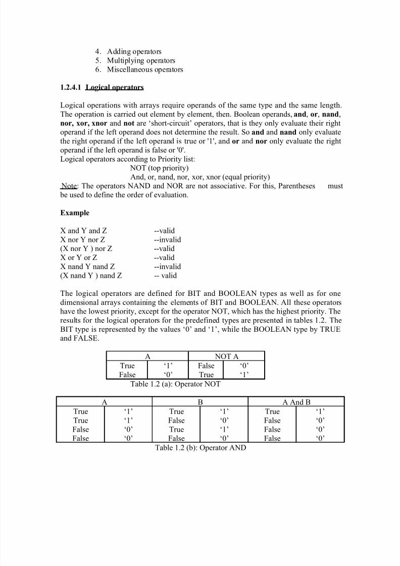
1.2.4.1 Logical operators
Logical operations with arrays require operands of the same type and the same length.The operation is carried out element by element, then. Boolean operands, and, or, nand,nor, xor, xnor and not are ‘short-circuit’ operators, that is they only evaluate their rightoperand if the left operand does not determine the result. So and and nand only evaluatethe right operand if the left operand is true or '1', and or and nor only evaluate the rightoperand if the left operand is false or '0'.Logical operators according to Priority list:
NOT (top priority)And, or, nand, nor, xor, xnor (equal priority)
Note: The operators NAND and NOR are not associative. For this, Parentheses must
be used to define the order of evaluation.
Example
X and Y and Z --validX nor Y nor Z --invalid(X nor Y ) nor Z --validX or Y or Z --validX nand Y nand Z --invalid(X nand Y ) nand Z -- valid
The logical operators are defined for BIT and BOOLEAN types as well as for onedimensional arrays containing the elements of BIT and BOOLEAN. All these operatorshave the lowest priority, except for the operator NOT, which has the highest priority. Theresults for the logical operators for the predefined types are presented in tables 1.2. TheBIT type is represented by the values ‘0’ and ‘1’, while the BOOLEAN type by TRUEand FALSE.
A NOT A
TrueFalse
‘1’‘0’
FalseTrue
‘0’‘1’
Table 1.2 (a): Operator NOT
A B A And B
TrueTrueFalseFalse
‘1’‘1’‘0’‘0’
TrueFalseTrueFalse
‘1’‘0’‘1’‘0’
TrueFalseFalseFalse
‘1’‘0’‘0’‘0’
Table 1.2 (b): Operator AND
8/4/2019 Unit-1(comp)
http://slidepdf.com/reader/full/unit-1comp 19/44
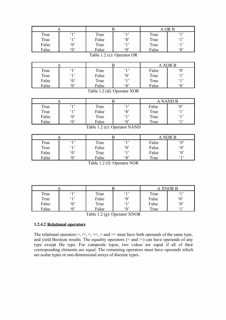
A B A OR B
TrueTrueFalseFalse
‘1’‘1’‘0’‘0’
TrueFalseTrueFalse
‘1’‘0’‘1’‘0’
TrueTrueTrueFalse
‘1’‘1’‘1’‘0’
Table 1.2 (c): Operator OR
A B A XOR B
TrueTrueFalseFalse
‘1’‘1’‘0’‘0’
TrueFalseTrueFalse
‘1’‘0’‘1’‘0’
FalseTrueTrueFalse
‘0’‘1’‘1’‘0’
Table 1.2 (d): Operator XOR
A B A NAND B
True
TrueFalseFalse
‘1’
‘1’‘0’‘0’
True
FalseTrueFalse
‘1’
‘0’‘1’‘0’
False
TrueTrueTrue
‘0’
‘1’‘1’‘1’
Table 1.2 (e): Operator NAND
A B A NOR B
TrueTrueFalseFalse
‘1’‘1’‘0’‘0’
TrueFalseTrueFalse
‘1’‘0’‘1’‘0’
FalseFalseFalseTrue
‘0’‘0’‘0’‘1’
Table 1.2 (f): Operator NOR
A B A XNOR B
TrueTrueFalseFalse
‘1’‘1’‘0’‘0’
TrueFalseTrueFalse
‘1’‘0’‘1’‘0’
TrueFalseFalseTrue
‘1’‘0’‘0’‘1’
Table 1.2 (g): Operator XNOR
1.2.4.2 Relational operators
The relational operators =, /=, <, <=, > and >= must have both operands of the same type,and yield Boolean results. The equality operators (= and /=) can have operands of anytype except file type. For composite types, two values are equal if all of their corresponding elements are equal. The remaining operators must have operands whichare scalar types or one-dimensional arrays of discrete types.
8/4/2019 Unit-1(comp)
http://slidepdf.com/reader/full/unit-1comp 20/44
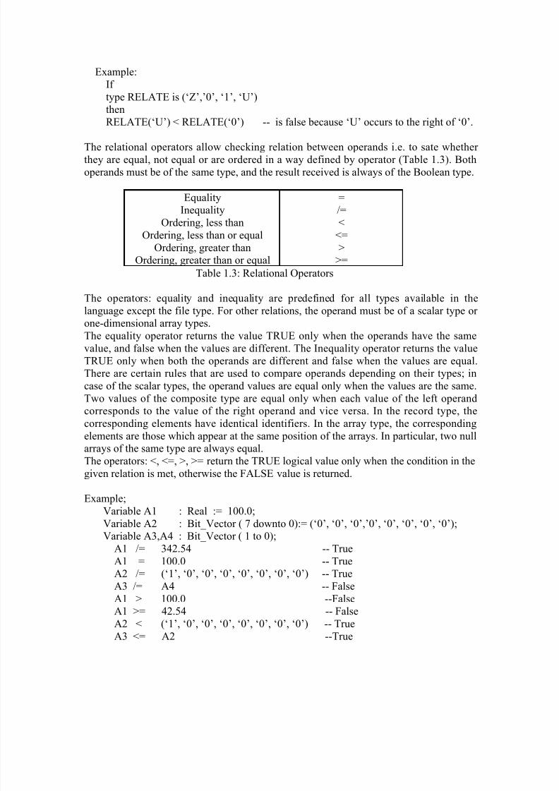
Example:If type RELATE is (‘Z’,’0’, ‘1’, ‘U’)thenRELATE(‘U’) < RELATE(‘0’) -- is false because ‘U’ occurs to the right of ‘0’.
The relational operators allow checking relation between operands i.e. to sate whether they are equal, not equal or are ordered in a way defined by operator (Table 1.3). Bothoperands must be of the same type, and the result received is always of the Boolean type.
EqualityInequality
Ordering, less thanOrdering, less than or equal
Ordering, greater thanOrdering, greater than or equal
=/=<
<=>
>=
Table 1.3: Relational Operators
The operators: equality and inequality are predefined for all types available in thelanguage except the file type. For other relations, the operand must be of a scalar type or one-dimensional array types.The equality operator returns the value TRUE only when the operands have the samevalue, and false when the values are different. The Inequality operator returns the valueTRUE only when both the operands are different and false when the values are equal.There are certain rules that are used to compare operands depending on their types; incase of the scalar types, the operand values are equal only when the values are the same.Two values of the composite type are equal only when each value of the left operand
corresponds to the value of the right operand and vice versa. In the record type, thecorresponding elements have identical identifiers. In the array type, the correspondingelements are those which appear at the same position of the arrays. In particular, two nullarrays of the same type are always equal.The operators: <, <=, >, >= return the TRUE logical value only when the condition in thegiven relation is met, otherwise the FALSE value is returned.
Example;Variable A1 : Real := 100.0;Variable A2 : Bit_Vector ( 7 downto 0):= (‘0’, ‘0’, ‘0’,’0’, ‘0’, ‘0’, ‘0’, ‘0’);Variable A3,A4 : Bit_Vector ( 1 to 0);
A1 /= 342.54 -- TrueA1 = 100.0 -- TrueA2 /= (‘1’, ‘0’, ‘0’, ‘0’, ‘0’, ‘0’, ‘0’, ‘0’) -- TrueA3 /= A4 -- FalseA1 > 100.0 --FalseA1 >= 42.54 -- FalseA2 < (‘1’, ‘0’, ‘0’, ‘0’, ‘0’, ‘0’, ‘0’, ‘0’) -- TrueA3 <= A2 --True
8/4/2019 Unit-1(comp)
http://slidepdf.com/reader/full/unit-1comp 21/44
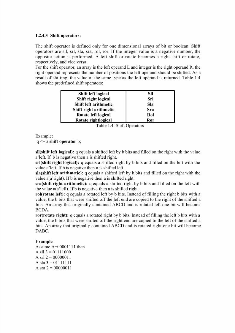
1.2.4.3 Shift operators:
The shift operator is defined only for one dimensional arrays of bit or boolean. Shiftoperators are sll, srl, sla, sra, rol, ror. If the integer value is a negative number, the
opposite action is performed. A left shift or rotate becomes a right shift or rotate,respectively, and vice versa.For the shift operator, an array is the left operand L and integer is the right operand R. theright operand represents the number of positions the left operand should be shifted. As aresult of shifting, the value of the same type as the left operand is returned. Table 1.4shows the predefined shift operators:
Shift left logical
Shift right logical
Shift left arithmetic
Shift right arithmetic
Rotate left logicalRotate rightlogical
Sll
Srl
Sla
Sra
RolRor
Table 1.4: Shift Operators
Example:q <= a shift operator b;
sll(shift left logical): q equals a shifted left by b bits and filled on the right with the valuea’left. If b is negative then a is shifted right.srl(shift right logical): q equals a shifted right by b bits and filled on the left with thevalue a’left. If b is negative then a is shifted left.
sla(shift left arithmetic): q equals a shifted left by b bits and filled on the right with thevalue a(a’right). If b is negative then a is shifted right.sra(shift right arithmetic): q equals a shifted right by b bits and filled on the left withthe value a(a’left). If b is negative then a is shifted right.rol(rotate left): q equals a rotated left by b bits. Instead of filling the right b bits with avalue, the b bits that were shifted off the left end are copied to the right of the shifted a bits. An array that originally contained ABCD and is rotated left one bit will becomeBCDA.ror(rotate right): q equals a rotated right by b bits. Instead of filling the left b bits with avalue, the b bits that were shifted off the right end are copied to the left of the shifted a bits. An array that originally contained ABCD and is rotated right one bit will becomeDABC.
Example
Assume A=00001111 thenA sll 3 = 01111000A srl 2 = 00000011A sla 3 = 01111111A sra 2 = 00000011

8/4/2019 Unit-1(comp)
http://slidepdf.com/reader/full/unit-1comp 22/44
A rol 3 = 00111100A ror 2 = 11000011A sll -1 = A srl 1 = 00000111A srl -4 = A sll 4 = 11110000A sla -1 = A sra 1 = 00000111
A sra -4 = A sla 4 = 11111111A rol -1 = A ror 1 = 10000111A ror -4 = A rol 4 = 11110000
Example:
Variable A5 : Bit_vector (3 downto 0):= (‘1’, ‘0’, ‘1’, ‘1’);
A5 sll 1 = (‘0’, ‘1’, ‘1’, ‘0’);A5 sll 3 = (‘1’, ‘1’, ‘1’, ‘1’);A5 sll -3 = A5 srl 3;
A5 srl 1 = (‘0’, ‘1’, ‘0’, ‘1’);A5 srl 3 = (‘0’, ‘0’, ‘0’, ‘1’);A5 srl -3 = A5 sll 3;A5 sla 1 = (‘0’, ‘1’, ‘1’, ‘1’);A5 sla 3 = (‘1’, ‘1’, ‘1’, ‘1’);A5 sla -3 = A5 sra 3;A5 sra 1 = (‘1’, ‘1’, ‘0’, ‘1’);A5 sra 3 = (‘1’, ‘1’, ‘1’, ‘1’);A5 sra -3 = A5 sla 3;A5 rol 1 = (‘0’, ‘1’, ‘1’, ‘1’);A5 rol 3 = (‘1’, ‘1’, ‘0’, ‘1’);A5 rol -3 = A5 ror 3;A5 ror 1 = (‘1’, ‘1’, ‘0’, ‘1’);A5 ror 3 = (‘0’, ‘1’, ‘1’, ‘1’);A5 ror -3 = A5 rol 3;
1.2.4.4 Adding operators
Adding operators consists of addition, subtraction and concatenation. The addingoperators are shown in table 1.5
AdditionSubtraction
Concatenation
+-&
Table 1.5: Adding Operators
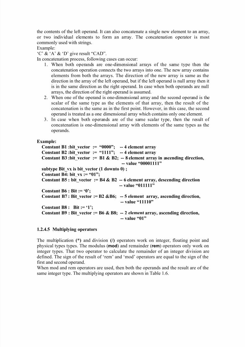
The sign operators (+ and –) and the addition (+) and subtraction (–) operators have their usual meaning on numeric operands. The concatenation operator (&) operates on one-dimensional arrays to form a new array with the contents of the right operand following
8/4/2019 Unit-1(comp)
http://slidepdf.com/reader/full/unit-1comp 23/44
the contents of the left operand. It can also concatenate a single new element to an array,or two individual elements to form an array. The concatenation operator is mostcommonly used with strings.Example:‘C’ & ‘A’ & ‘D’ give result “CAD”.
In concatenation process, following cases can occur:1. When both operands are one-dimensional arrays of the same type then theconcatenation operation connects the two arrays into one. The new array containselements from both the arrays. The direction of the new array is same as thedirection in the array of the left operand, but if the left operand is null array then itis in the same direction as the right operand. In case when both operands are nullarrays, the direction of the right operand is assumed.
2. When one of the operand is one-dimensional array and the second operand is thescalar of the same type as the elements of that array, then the result of theconcatenation is the same as in the first point. However, in this case, the secondoperand is treated as a one dimensional array which contains only one element.
3. In case when both operands are of the same scalar type, then the result of concatenation is one-dimensional array with elements of the same types as theoperands.
Example:
Constant B1 :bit_vector := “0000”; -- 4 element array
Constant B2 :bit_vector := “1111”; -- 4 element array
Constant B3 :bit_vector := B1 & B2; -- 8 element array in ascending direction,
-- value “00001111”
subtype Bit_vx is bit_vector (1 downto 0) ;
Constant B4: bit_vx := “01”;
Constant B5 : bit_vector := B4 & B2 -- 6 element array, descending direction
-- value “011111”
Constant B6 : Bit := ‘0’;
Constant B7 : Bit_vector := B2 &B6; -- 5 element array, ascending direction,
-- value “11110”
Constant B8 : Bit := ‘1’;
Constant B9 : Bit_vector := B6 & B8; -- 2 element array, ascending direction,
-- value “01”
1.2.4.5 Multiplying operators
The multiplication (*) and division (/) operators work on integer, floating point and physical types types. The modulus (mod) and remainder (rem) operators only work oninteger types. That two operator to calculate the remainder of an integer division aredefined. The sign of the result of ‘rem’ and ‘mod’ operators are equal to the sign of thefirst and second operand.When mod and rem operators are used, then both the operands and the result are of thesame integer type. The multiplying operators are shown in Table 1.6.
8/4/2019 Unit-1(comp)
http://slidepdf.com/reader/full/unit-1comp 24/44
MultiplicationDivisionModulus
Remainder
*/
modrem
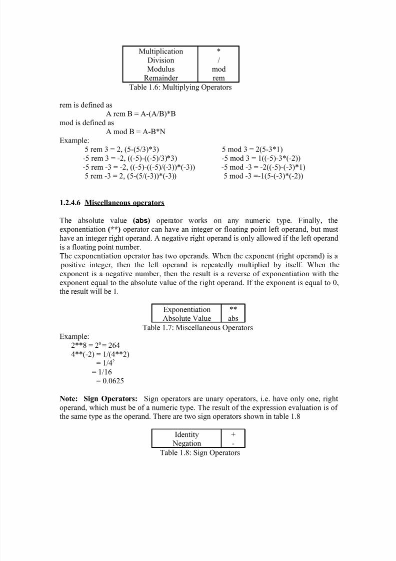
Table 1.6: Multiplying Operators
rem is defined asA rem B = A-(A/B)*B
mod is defined asA mod B = A-B*N
Example:5 rem 3 = 2, (5-(5/3)*3) 5 mod 3 = 2(5-3*1)-5 rem 3 = -2, ((-5)-((-5)/3)*3) -5 mod 3 = 1((-5)-3*(-2))-5 rem -3 = -2, ((-5)-((-5)/(-3))*(-3)) -5 mod -3 = -2((-5)-(-3)*1)5 rem -3 = 2, (5-(5/(-3))*(-3)) 5 mod -3 =-1(5-(-3)*(-2))
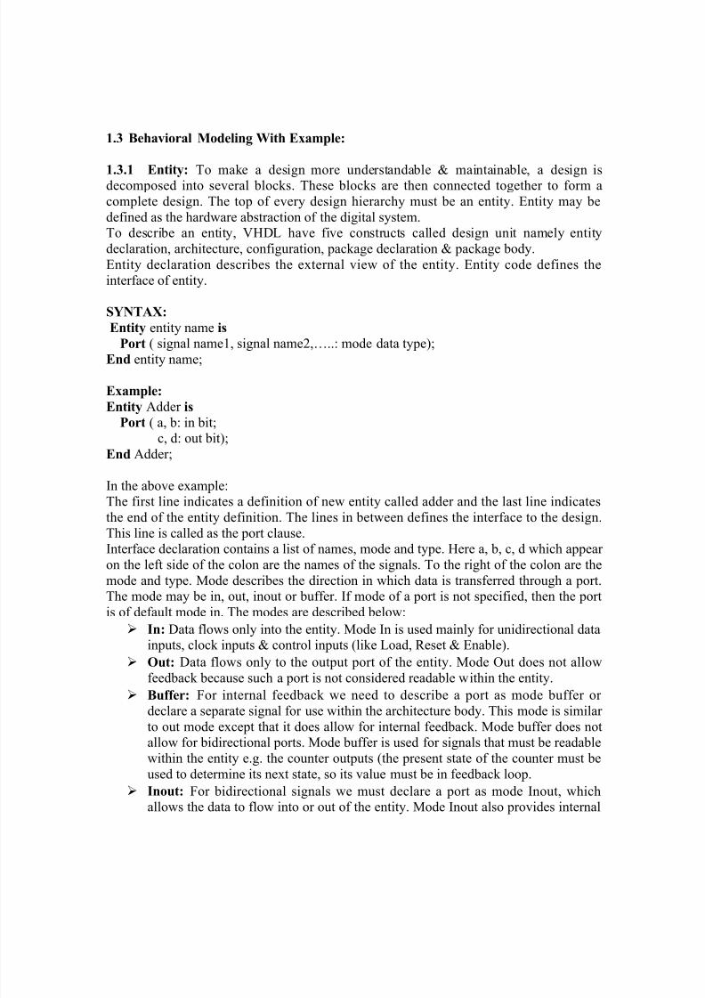
1.2.4.6 Miscellaneous operators
The absolute value (abs) operator works on any numeric type. Finally, theexponentiation (**) operator can have an integer or floating point left operand, but musthave an integer right operand. A negative right operand is only allowed if the left operandis a floating point number.The exponentiation operator has two operands. When the exponent (right operand) is a positive integer, then the left operand is repeatedly multiplied by itself. When theexponent is a negative number, then the result is a reverse of exponentiation with theexponent equal to the absolute value of the right operand. If the exponent is equal to 0,
the result will be 1.
ExponentiationAbsolute Value
**abs
Table 1.7: Miscellaneous OperatorsExample:
2**8 = 28 = 2644**(-2) = 1/(4**2)
= 1/42
= 1/16= 0.0625
Note: Sign Operators: Sign operators are unary operators, i.e. have only one, rightoperand, which must be of a numeric type. The result of the expression evaluation is of the same type as the operand. There are two sign operators shown in table 1.8
Identity Negation
+-
Table 1.8: Sign Operators
8/4/2019 Unit-1(comp)
http://slidepdf.com/reader/full/unit-1comp 25/44
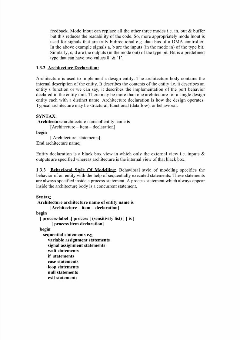
1.3 Behavioral Modeling With Example:
1.3.1 Entity: To make a design more understandable & maintainable, a design isdecomposed into several blocks. These blocks are then connected together to form acomplete design. The top of every design hierarchy must be an entity. Entity may bedefined as the hardware abstraction of the digital system.To describe an entity, VHDL have five constructs called design unit namely entitydeclaration, architecture, configuration, package declaration & package body.Entity declaration describes the external view of the entity. Entity code defines theinterface of entity.
SYNTAX:
Entity entity name is
Port ( signal name1, signal name2,…..: mode data type);End entity name;
Example:
Entity Adder isPort ( a, b: in bit;
c, d: out bit);End Adder;
In the above example:The first line indicates a definition of new entity called adder and the last line indicatesthe end of the entity definition. The lines in between defines the interface to the design.This line is called as the port clause.Interface declaration contains a list of names, mode and type. Here a, b, c, d which appear on the left side of the colon are the names of the signals. To the right of the colon are themode and type. Mode describes the direction in which data is transferred through a port.The mode may be in, out, inout or buffer. If mode of a port is not specified, then the portis of default mode in. The modes are described below:
In: Data flows only into the entity. Mode In is used mainly for unidirectional datainputs, clock inputs & control inputs (like Load, Reset & Enable).
Out: Data flows only to the output port of the entity. Mode Out does not allowfeedback because such a port is not considered readable within the entity.
Buffer: For internal feedback we need to describe a port as mode buffer or declare a separate signal for use within the architecture body. This mode is similar to out mode except that it does allow for internal feedback. Mode buffer does notallow for bidirectional ports. Mode buffer is used for signals that must be readablewithin the entity e.g. the counter outputs (the present state of the counter must beused to determine its next state, so its value must be in feedback loop.
Inout: For bidirectional signals we must declare a port as mode Inout, whichallows the data to flow into or out of the entity. Mode Inout also provides internal
8/4/2019 Unit-1(comp)
http://slidepdf.com/reader/full/unit-1comp 26/44
feedback. Mode Inout can replace all the other three modes i.e. in, out & buffer but this reduces the readability of the code. So, more appropriately mode Inout isused for signals that are truly bidirectional e.g. data bus of a DMA controller.In the above example signals a, b are the inputs (in the mode in) of the type bit.Similarly, c, d are the outputs (in the mode out) of the type bit. Bit is a predefined
type that can have two values 0’ & ‘1’.
1.3.2 Architecture Declaration:
Architecture is used to implement a design entity. The architecture body contains theinternal description of the entity. It describes the contents of the entity i.e. it describes anentity’s function or we can say, it describes the implementation of the port behavior declared in the entity unit. There may be more than one architecture for a single designentity each with a distinct name. Architecture declaration is how the design operates.Typical architecture may be structural, functional (dataflow), or behavioral.
SYNTAX:
Architecture architecture name of entity name is
[Architecture – item – declaration]begin
[ Architecture statements]End architecture name;
Entity declaration is a black box view in which only the external view i.e. inputs &outputs are specified whereas architecture is the internal view of that black box.
1.3.3 Behavioral Style Of Modelling: Behavioral style of modeling specifies the behavior of an entity with the help of sequentially executed statements. These statementsare always specified inside a process statement. A process statement which always appear inside the architecture body is a concurrent statement.
Syntax: Architecture architecture name of entity name is
[Architecture – item – declaration]
begin
[ process-label :] process [ (sensitivity list) ] [ is ]
[ process item declaration]
begin
sequential statements e.g.
variable assignment statements
signal assignment statements
wait statements
if statements
case statements
loop statements
null statements
exit statements
8/4/2019 Unit-1(comp)
http://slidepdf.com/reader/full/unit-1comp 27/44
next statements etc
End process [ process-label];
End architecture name;
In this syntax, process label is a name given to the process & is optional. Sensitivity list is
the list of signals to which the process is sensitive i.e. whenever there is an event on anyof the elements of the sensitivity list, the process starts executing. Process never ends, italways suspends. After the last sequential statement process enters into wait state andwaits for another event to occur on any of the elements of the sensitivity list.Process item declaration is optional & can be used only within the process.
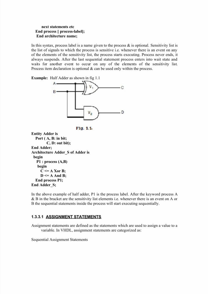
Example: Half Adder as shown in fig 1.1
Entity Adder is
Port ( A, B: in bit;
C, D: out bit);
End Adder;
Architecture Adder_S of Adder is
begin
P1 : process (A,B)
begin
C <= A Xor B;
D <= A And B;
End process P1;
End Adder_S;
In the above example of half adder, P1 is the process label. After the keyword process A& B in the bracket are the sensitivity list elements i.e. whenever there is an event on A or B the sequential statements inside the process will start executing sequentially.
1.3.3.1 ASSIGNMENT STATEMENTS
Assignment statements are defined as the statements which are used to assign a value to avariable. In VHDL, assignment statements are categorized as:
Sequential Assignment Statements
8/4/2019 Unit-1(comp)
http://slidepdf.com/reader/full/unit-1comp 28/44
Concurrent Assignment Statements
1.3.3.2 SEQUENTIAL STATEMENTS
Sequential statements execute in the sequence in which they appear in a program. Incontrast to concurrent statements, sequential statements are not event triggered.
Sequential statements are identical to concurrent statements in terms of its behavior. If astatement appears outside a process in a architecture body, it is a concurrent statementwhereas the same statement is sequential when appears inside a process statement.Sequential statements are used to define algorithms to express the behavior of a designentity. These statements appear in process statements and in subprograms (proceduresand functions).
1.3.4 PROCESS STATEMENT
An independent sequential process represents the behavior of some portion of a design.The body of a process is a list of sequential statements, but itself, process statement is a
concurrent statement.
Syntax: label: process (sensitivity list)
local declarations
begin
sequential statements
end process label;
Example:
DFF: process (clock)begin
if clock = '1' then
Q <= D after 5ns;
QN <= not D after 5ns;
end if;
end process DFF;
The sequential statements in the process are executed in order, commencing with the beginning of simulation. After the last statement of a process has been executed, the process is repeated from the first statement, and continues to repeat until suspended. If
the optional sensitivity list is not given, a wait on ... statement is inserted after the lastsequential statement, causing the process to be suspended at that point until there is anevent on one of the signals in the list, at which time processing resumes with the firststatement in the process.In the above example, after keyword process the sensitivity list consists of clock i.e.whenever there is an event on clock the process executes. DFF is the process label whichis optional. Process body starts after keyword begin & ends at keyword End Process.The statements between begin & End are sequential statements. If there are any

8/4/2019 Unit-1(comp)
http://slidepdf.com/reader/full/unit-1comp 29/44
declaration between keyword process & begin they are called local declarations as theyare available only inside the process. If there is no sensitivity list elements after thekeyword process i.e. the bracket after keyword process is empty, then we use waitstatements to suspend the process. If both sensitivity list & the wait statements are notspecified, then the process will execute infinitely. It is an error to use both the sensitivity
list & the wait statements together in one process.The sequential statements used in process are:
1.3.4.1 Variable Assignment Statements: Variable assignment statements are used for assigning a value to a variable. The variableassignment statement replaces the current value of a variable with the new valuespecified by the expression. The variable and the expression must be of the same basetype. In VHDL, local variables can only be declared in the declaration part of a processstatement and a subprogram.
Syntax:
Variable-object := expression;
When the statement is executed & the expression is evaluated, its value is assigned to thevariable object instantaneously i.e. without any delay. The variable holds its value for theentire simulation time as the process never exits, & is either active or waiting for an eventto occur & become active.
Example:
entity ASSIGN is
-- Port declaration statement
end ASSIGN;
architecture arch of VARASSIGN is
signal A, B, C: std_logic_vector (3 downto 0);
begin
P0: process (A, B, C)
variable x, y, z: std_logic_vector (3 downto 0);
variable x: bit;
begin
---- Some concurrent statements
end process p0;
end arch;
1.3.4.2 Signal assignment statements: Signal assignment statements are used for assigning a value to a signal. The signal assignment statement has unique properties whenused sequentially.
Syntax:
Signal-object := expression [ after delay-value] ;

8/4/2019 Unit-1(comp)
http://slidepdf.com/reader/full/unit-1comp 30/44
The value expression in the right-hand side of the signal assignment statement is similar to the variable assignment statement. Unlike a variable object, signal object is assignedthe value after a delay. This delay is either defined by using a after clause or will take thedefault value i.e. delta delay. Outside the process this statement is a concurrent statement
whereas when used inside a process it is a sequential statement.
Example:
Sig <= Sa and Sb or Sc;
sig3 <= transport sig4 after 3 ns;
Local variable are different from signal in writing VHDL code. They are summarized asfollows:1. Local variables are declared and only visible inside a process or subprogram. Signalscannot be declared inside a process or a subprogram.
2. The new value of a local variable is immediately updated when the variableAssignment statement is executed. A Signal assignment statement is updated as afunction of the signal drivers when the process is suspended.3. Only signals can be used to communicate among concurrent statements. Ports declaredin the entity are signals. Subprogram arguments can be signals or Variables.
1.3.4.3 Wait statements: As we have seen in the above example that wait statement isused as an alternative for sensitivity list in a process. It is used to suspend a process after last sequential statement in a process. Basically there are three types of wait statementsi.e.
1) Wait on sensitivity list;
Example: process()
………
………
Wait on A,B;
End process;
2) Wait until Boolean expression
In this type of wait statement the process remains suspended until a givencondition is not fulfilled.Example:
Wait until A=B;
3) Wait for time expression
Example: Wait for 2ns;
8/4/2019 Unit-1(comp)
http://slidepdf.com/reader/full/unit-1comp 31/44
In this type of wait statement the process remains suspended for the timespecified as in the above example process remains suspended for 2ns.
1.3.5 Conditional Statements:
Standard if..then and case constructs can be used for selective operations.
1.3.5.1 If Statements: If statements are used to implement the decision controlinstruction. It selects a sequence of statements for execution based on the value of acondition.
Syntax:
If Boolean expression then
Sequential statements
[ elsif Boolean expression then
Sequential statements ]
[ else
Sequential statements ]End if;
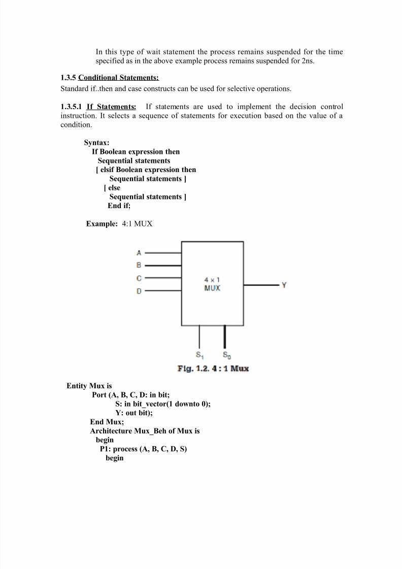
Example: 4:1 MUX
Entity Mux is
Port (A, B, C, D: in bit;S: in bit_vector(1 downto 0);
Y: out bit);
End Mux;
Architecture Mux_Beh of Mux is
begin
P1: process (A, B, C, D, S)
begin
8/4/2019 Unit-1(comp)
http://slidepdf.com/reader/full/unit-1comp 32/44
if S = “00 ” then
Y<= A;
elsif S = “01 ” then
Y<= B;
elsif S = “10 ” then
Y<= C;else
Y<= D;
End if;
End process P1;
End Mux_Beh;
1.3.5.2 Case statements: Case statements allow to make a decision from a number of choices. They are used to specify a set of statements to execute based on the value of agiven selection signal.
Syntax: Case expression is
When choices => sequential statements
When choices => sequential statements
.
.
[ When others => sequential statements ]
End case;
Example: 4:1 MUX (shown in fig 1.2)
Entity Mux is
Port ( A, B, C, D: in bit;
S: in bit_vector(1 downto 0);
Y: out bit);
End Mux;
Architecture Mux_Beh of Mux is
begin
P1: process (A, B, C, D, S)
begin
Case S is
When “00” => Y<= A;
When “01” => Y<= B;
When “10” => Y<= C;
When “11” => Y<= D;
When others => null;
End case;
End process P1;
End Mux_Beh;

8/4/2019 Unit-1(comp)
http://slidepdf.com/reader/full/unit-1comp 33/44
More than one values may be specified by separating by a symbol “|” e.g. “00”| “01”.
1.3.5.3 Loop Statements: The versatility of a programming language lies in its ability to perform a set of instructions repeatedly. This repetitive operation is done through acontrol loop structure. A loop statement is used to iterate through a set of sequential
statements. There are three kinds of iteration statements.
1) The first form of the iteration scheme is for the scheme.
Syntax:
[ label: ] for variable in range loop
sequence-of-statements
end loop [ label ] ;
Example:
A := 1;
for I in 1 to 10 loop
A := A +I;end loop;
In this example, loop executes for 10 times & each time the value of I is incremented by 1.
2) The second form of the iteration scheme is the while scheme.
Syntax:
[ label: ] while condition loop
sequence-of-statements
end loop [ label ] ;
Example:
A := 1,B:=1;
while A <10 loop
B := B +1;
end loop;
In this example, loop executes for 10 times & each time the value of A is incremented by 1
3) The third form of the iteration scheme is the one where no iteration scheme isspecified.
Syntax:
[ label: ] loop
sequence-of-statements
end loop [ label ] ;
8/4/2019 Unit-1(comp)
http://slidepdf.com/reader/full/unit-1comp 34/44
Example:
A := 1,B:=1;
Loop
B := B +1;
A := A +1;
exit when A > 10;end loop;
All kinds of the loops may contain the 'next' and 'exit' statements.
1.3.5.4 Null Statements: These statements are used when nothing is required to be done.Execution continues with the statement which is appearing next to the null statement.Wherever in the program, we need to use this statement, we simply write
null
The example for null statement is the same as used for case statement. This statement
can be used in if statement or in case statement where certain condition is to be satisfied.Null statement can be used to indicate that when some conditions are met, no action isto performed.
Example:
Case ABC is
When “001” => Y1 := A and B;
When “010” => Y2:= A or B;
When “100” => Y3:= Not A;
When others => null;
1.3.5.5 Exit statements: A statement that may be used in a loop to immediately exit theloop.
Syntax: [ label: ] exit [ label2 ] [ when condition ] ;
Label2 identifies the loop from which the execution jumps out. If no label is defined, theexecution jumps out of the innermost loop.
Example:
exit;
exit outer_loop;
exit when A>B;
exit this_loop when C=D or done; -- done is a Boolean variable
The exit statement terminates entirely the execution of the loop in which it is located. Theexecution of the exit statement depends on a condition placed at the end of statementright after the WHEN reserved word. When the condition is TRUE (or if there is no
8/4/2019 Unit-1(comp)
http://slidepdf.com/reader/full/unit-1comp 35/44
condition at all), the exit statement is executed and the control is passed to the firststatement after the end loop.
1.3.5.6 Next statements: A statement that may be used in a loop to cause the nextiteration. This statement can only be used inside a loop & it replaces the keyword exit.
Next statement skips the remaining statements and execution goes to next iteration of theloop.Syntax :
[ label: ] next [ label2 ] [ when condition ] ;
Example:
next; next outer_loop;
next when A>B;
next this_loop when C=D or done; -- done is a Boolean variable
The NEXT statement allows to skip a part of an iteration loop. If the condition specifiedafter the WHEN reserved word is TRUE, or if there is no condition at all, then thestatement is executed. This results in skipping all the statements below it until the end of the loop & passing the control to the first statement in the next iteration.A NEXT statement may specify the name of the loop it is expected to influence. If nolabel is supported, then the statement applies to the innermost enclosing loop.The NEXT statement is often confused with the EXIT statement. The difference betweenthe two is that the EXIT statement “exits” the loop entirely, while the NEXT statementskips to the “next” loop iteration (in other words, it “exits” the current iteration of theloop.
1.3.5.7 Assertion statement: Assertion statement is used for internal consistency check or error message generation.
Syntax :
[ label: ] assert
boolean_condition
[ report string ][ severity name ] ;
Example: assert a=(b or c);
assert j<i report "internal error, tell someone";
assert clk='1' report "clock not up" severity WARNING;
Predefined severity names are: NOTE, WARNING, ERROR, FAILURE.Default severity for assert is ERROR.
8/4/2019 Unit-1(comp)
http://slidepdf.com/reader/full/unit-1comp 36/44
The assertion statement has three optional fields and usually all three are used. Thecondition specified in an assertion statement must evaluate to a Boolean value (TRUE or FALSE). If it is FALSE, it is said that an assertion violation occurred. The expressionspecified in the report clause must be of predefined type STRING and is a message to bereported when assertion violation occurred.
If the severity clause is present, it must specify an expression of predefined typeSEVERITY_LEVEL, which determines the severity level of the assertion violation. TheSEVERITY_LEVEL type is specified in the standard package and contains the followingvalues: NOTE, WARNING, ERROR and FAILURE.
If the severity clause is omitted it is implicitly assumed to be ERROR.When an assertion violation occurs, the report clause is issued and displayed on thescreen. The supported severity level supplies information to the simulator. The severitylevel defines the degree to which the violation of the assertion affects the operation of the process.
NOTE can be used to pass information messages from simulation.
WARNING can be used in unusual situation in which the simulation can becontinued, but the results may be unpredictable.
ERROR can be used when the assertion violation makes continuation of thesimulation not feasible.
FAILURE can be used when the assertion violation is a fatal error & thesimulation must be stopped at once.
Assertion statements are not only sequential, but can be used as concurrent statements aswell. A concurrent assertion statement represents a passive process statement containingthe specified assertion statement.
1.3.5.8 R eport statement: Report statement is used to output messages. It is similar toassertion statement except that it does not have the assertion check.
Syntax :
[ label: ] report string [ severity name ] ;
report "finished pass1"; -- default severity name is NOTE
report "Inconsistent data." severity FAILURE;
The report statement is very much similar to assertion statement. The main difference isthat the message is displayed unconditionally. Its main purpose is to help in thedebugging process. The expression specified in the report clause must be of predefinedtype STRING, and it is a message that will be reported when the assertion violationoccurred.The report statement was introduced as late as in VHDL’93 and is equivalent to the assertfalse statement. The latter form was the only acceptable form in VHDL’83.
1.3.5.9 Procedure call statement:
8/4/2019 Unit-1(comp)
http://slidepdf.com/reader/full/unit-1comp 37/44
Procedure call statement invoke an externally-defined subprogram in the same manner asa concurrent procedure call. A procedure call statement can either be a sequentialstatement or concurrent statement. If the statement is inside a process statement or another subprogram, it is sequential procedure call statement otherwise concurrent procedure call statement
Syntax :
[ label: ] procedure-name [ ( actual parameters ) ] ;
Actual parameters specifies the list of formal parameters for the procedure. Actuals may be specified using positional association or named association.
Example:
do_it; -- no actual parameters
compute(stuff, A=>a, B=>c+d); -- positional association first,-- then named association of
-- formal parameters to actual parameters
1.3.5.10 Return Statement:
Return statement is a special STATEMENT allowed only within subprograms. It is arequired statement in a function, optional in a procedure.
Syntax :
[ label: ] return [ expression ] ;
Return statement causes the subprogram to terminate & control to be returned to thecalling program.
return; -- from somewhere in a procedure
return a+b; -- returned value in a function
The return statement ends the execution of a subprogram (Procedure or function) inwhich it appears. It causes an unconditional jump to the end of the subprogram.If a return statement appears inside nested subprogram it applies to the innermostsubprogram (i.e. the jump is performed to the next end procedure or end function clause).This statement can only be used in a procedure or function body. The return statement in
a procedure may not return any value, while a return in a function must return a value (anexpression) which is of the same type as specified in the function after the returnkeyword.
1.3.6 Delays:
8/4/2019 Unit-1(comp)
http://slidepdf.com/reader/full/unit-1comp 38/44
Delay is a mechanism allowing to introduce timing parameters of specified systems. Thedelay mechanism allows introducing propagation times of described systems. Delays arespecified in signal assignment statements. It is not allowed to specify delays in variableassignment.
In an actual digital system when a input changes, output changes only after a delay. InVHDL delay is specified by using a delay statement. The delay is of two types:
• Inertial Delay
• Transport Delay 1.3.6.1 Inertial Delay: Inertial delay is defined using the reserved word Inertial and is used to model the devices,which are inherently inertial. In practice, this means, that impulses shorter that specifiedswitching time are not transmitted.Inertial delay specifications may contain a reject clause. This clause can be used to
specify the minimum impulse width that will be propagated, regardless of the switchingtime specified. If the delay mechanism is not specified then by default it is inertial.If a narrow pulse having width less than the delay time appears at the input then the pulseis not passed to the output i.e. if the input is not stable for the specified limit, no outputchange occurs. The limit or duration for which the input must be stable is called as the pulse rejection limit.
SYNTAX:
Signal-object <= [ [ reject pulse rejection limit] inertial] expression after inertial-
delay- value;
If no rejection limit is specified, the default limit is the inertial delay value itself.Rejection limit value cannot be negative or greater than inertial delay value.
Example: Z <= reject 5ns inertial Y after 12ns;In this example, input pulse will not be passed to the output if it is not stable for at least5ns & will be rejected.
Z <= inertial Y after 12ns;In this example, no rejection limit is specified so the limit is of inertial delay value itself i.e. input pulse will not be passed to the output if it is not stable for at least 12ns & will berejected. This statement is similar to the statement given below i.e. both will have the
same impact
Z <= Y after 12ns;
1.3.6.2 Transport Delay:
Transport delay is specified using the reserved word transport and is characteristic for transmission line. New signal value is assigned with specified delay independently fromthe width of the impulse in the waveform.

8/4/2019 Unit-1(comp)
http://slidepdf.com/reader/full/unit-1comp 39/44
Unlike Inertial delay, transport delay repeats the input waveform after the specified delayirrespective of the pulse width. It is a pure propagation delay. The keyword transportmust be used in the signal assignment statement to represent transport delay. This is theideal type of delay model as the spikes are also propagated to the output which areignored in inertial delay. If not specified then the delay is of inertial type. This delay
statement can be expressed as :Z<= Transport Y after 12 ns;
If no delay ( i.e. after clause) is specified or a delay of 0ns is specified, a default type of delay called delta delay is assumed. It represents an infinitesimally small delay which islogically equivalent to one evaluation cycle.
Examples
B <= A after 5ns; -- inertial delayC <= transport A after 5 ns; -- transport delay
Where there are multiple drivers for one signal, a "resolution function" must be providedto determine the value to be assigned to the signal from the values supplied by themultiple drivers. This allows simulation of buses with multiple sources/drivers.
NOTE: The std_logic and std_logic_vector types from the ieee library have predefinedresolution functions:
Example:
signal data_line: std_logic;
begin
block1:
data_line <= '1'; -- one driver
...
block2:
data_line <= 'Z'; -- 2nd driver
8/4/2019 Unit-1(comp)
http://slidepdf.com/reader/full/unit-1comp 40/44
The resolved value is '1' since '1' overrides a 'Z' (floating) value. If the two values had been '1' and '0', the resolved value would have been 'X', indicating an unknown result.
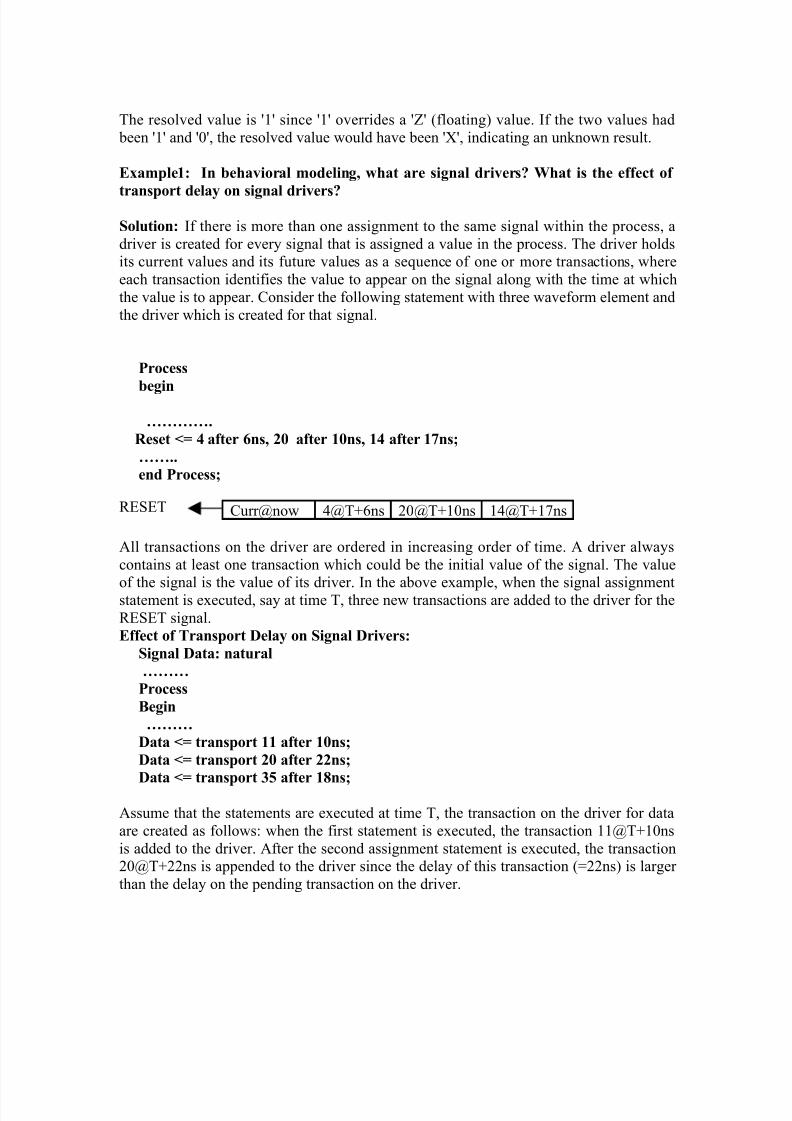
Example1: In behavioral modeling, what are signal drivers? What is the effect of
transport delay on signal drivers?
Solution: If there is more than one assignment to the same signal within the process, adriver is created for every signal that is assigned a value in the process. The driver holdsits current values and its future values as a sequence of one or more transactions, whereeach transaction identifies the value to appear on the signal along with the time at whichthe value is to appear. Consider the following statement with three waveform element andthe driver which is created for that signal.
Process
begin
………….
Reset <= 4 after 6ns, 20 after 10ns, 14 after 17ns;
……..
end Process;
Curr@now 4@T+6ns 20@T+10ns 14@T+17ns
All transactions on the driver are ordered in increasing order of time. A driver alwayscontains at least one transaction which could be the initial value of the signal. The value
of the signal is the value of its driver. In the above example, when the signal assignmentstatement is executed, say at time T, three new transactions are added to the driver for theRESET signal.Effect of Transport Delay on Signal Drivers:
Signal Data: natural
………
Process
Begin
………
Data <= transport 11 after 10ns;
Data <= transport 20 after 22ns;
Data <= transport 35 after 18ns;
Assume that the statements are executed at time T, the transaction on the driver for dataare created as follows: when the first statement is executed, the transaction 11@T+10nsis added to the driver. After the second assignment statement is executed, the transaction20@T+22ns is appended to the driver since the delay of this transaction (=22ns) is larger than the delay on the pending transaction on the driver.
RESET
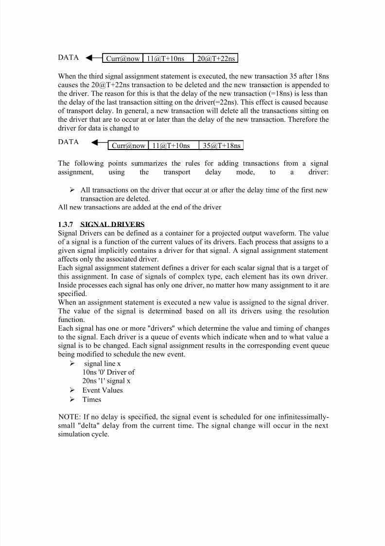
8/4/2019 Unit-1(comp)
http://slidepdf.com/reader/full/unit-1comp 41/44
Curr@now 11@T+10ns 20@T+22ns
When the third signal assignment statement is executed, the new transaction 35 after 18nscauses the 20@T+22ns transaction to be deleted and the new transaction is appended to
the driver. The reason for this is that the delay of the new transaction (=18ns) is less thanthe delay of the last transaction sitting on the driver(=22ns). This effect is caused becauseof transport delay. In general, a new transaction will delete all the transactions sitting onthe driver that are to occur at or later than the delay of the new transaction. Therefore thedriver for data is changd to
Curr@now 11@T+10ns 35@T+18ns
The following points summarizes the rules for adding transactions from a signalassignment, using the transport delay mode, to a driver:
All transactions on the driver that occur at or after the delay time of the first newtransaction are deleted.
All new transactions are added at the end of the driver
1.3.7 SIGNAL DRIVERS
Signal Drivers can be defined as a container for a projected output waveform. The valueof a signal is a function of the current values of its drivers. Each process that assigns to agiven signal implicitly contains a driver for that signal. A signal assignment statementaffects only the associated driver.Each signal assignment statement defines a driver for each scalar signal that is a target of this assignment. In case of signals of complex type, each element has its own driver.
Inside processes each signal has only one driver, no matter how many assignment to it arespecified.When an assignment statement is executed a new value is assigned to the signal driver.The value of the signal is determined based on all its drivers using the resolutionfunction.Each signal has one or more "drivers" which determine the value and timing of changesto the signal. Each driver is a queue of events which indicate when and to what value asignal is to be changed. Each signal assignment results in the corresponding event queue being modified to schedule the new event.
signal line x10ns '0' Driver of
20ns '1' signal x Event Values
Times
NOTE: If no delay is specified, the signal event is scheduled for one infinitessimally-small "delta" delay from the current time. The signal change will occur in the nextsimulation cycle.
DATA
DATA
8/4/2019 Unit-1(comp)
http://slidepdf.com/reader/full/unit-1comp 42/44
Example:
(Assume current time is T)
clock <= not clock after 10ns; -- change at T + 10ns
databus <= mem1 and mem2 after delay; -- change at T + delay
x <= '1'; -- change to '1' at time T + "delta";
Summary:
• VHDL stands for VHSIC (Very High Speed Integrated Circuit) HardwareDescription language
Modeling of digital system
Concurrent and sequential statement
Machine readable specification
Design life time>designer life time
• VHDL is a case insensitive language
• VHDL History
Early ‘70s: initial discussions
Late ‘70s: definitions of requirements
Mid ’82: contract of development with IBM, intermetrics and TI
Mid ’84: version 7.2
Mid ’86: IEEE – standard
1987 DoD adopts the standard-> IEEE.1076
mid ’88: increasing support by CAE manufacturers
late ’91: revision 1993: new standard
1999: VHDL – AMS extension
• VHDL is a CAD tool
• VHDL is technology independent i.e. it does not enforce a design methodology ona designer.
• VHDL is suitable for the design phases from system level to gate level
• VHDL provides abstraction capabilities
• VHDL is used for documentation, verification & synthesis of large digital design.
• Basic & extended are the two types of identifiers used in VHDL
• Data Object are used for holding a value of a specified type

8/4/2019 Unit-1(comp)
http://slidepdf.com/reader/full/unit-1comp 43/44
• Data Object can belong to any of the following various classes:1. Constant 2. Variable3. Signal 4. File
•Any variables used in the program must be declared before using it. This is donewith the help of data types.
• Data type are classified into four categories1. Scalar type 2. Composite type3. Access type 4. File type
• A scalar type encompasses four classes of types.1. Integer type 2. Physical type3. Floating type 4. Enumerated type
• Composite types encompasses two classes of types.1. Array 2. Record
• Array is a collection of values of similar type whereas record is a collection of values of different types.
• Operators are classified into the following six categories:o Logical operators
o Relational operators
o Shift operatorso Adding operators
o Multiplying operators
o Miscellaneous operators
• In VHDL, delays are of two types :
1. Inertial Delay 2. Transport Delay
• In VHDL, the default type of delay is Delta delay which is equivalent to oneevaluation cycle.
• Entity is the hardware abstraction or external view of a digital system.
• Architecture declaration is the external view or implementation of design entity.
• Architecture declaration can be modeled using any of the following four styles of modeling:
8/4/2019 Unit-1(comp)
http://slidepdf.com/reader/full/unit-1comp 44/44
1. Structural Style of Modelling2. Data Flow Style of Modelling3. Behavioral Style of Modelling4. Mixed Style of Modelling
Exercise:
1. What is the role of HDL in digital system design? How do HDL differ from other software language?
2. List out the capabilities of VHDL.[MDU, DSD Dec 2004, 2006]
3. What is the Data Object? Explain its all categories.4. Define Data type and discuss its types in brief.5. What is the operator? Define its all types. Explain shift operators in detail.
[MDU, DSD Dec 2004]
6. Why do we require signal driver? Explain with example.7. How does transport delay differ from inertial delay?8. Explain entity with syntax and example.9. What is the architecture declaration? Define its all types.
10. What are the steps involved in implementation and analysis of digital system?[MDU, DSD Dec 2004]
11. What are the different specifications for the design of digital system?[MDU, DSD May 2005]
12. What is VHDL? Who formulated the rules for VHDL? What are its specific
capabilities?[MDU, DSD May 2006]
13. What are identifiers? How many types of identifiers are there? How do we useidentifiers? Explain with example.
[MDU, DSD May 2005, 2006, Dec 2006]14. Enumerate the difference between Data Object and Data Types?
[MDU, DSD May 2005]15. What are Data Types? Explain all its types with program examples.
[MDU, DSD Dec 2005]16. Differentiate between sub and scalar types of data types.
[MDU, DSD May2006] 17. In behavioral modeling, explain inertial and transport delay
[MDU, DSD Dec 2005]