ultrasound basics - conquest imaging...ultrasound transducers used in diagnostic imaging employ an...
TRANSCRIPT

Ultrasound Basics
Presented by: Matt [email protected] Imagingwww.conquestimaging.com
© 2016 Conquest Imaging
Agenda
Introduction and Welcome
Ultrasound Basics
Ultrasound Types
Building Blocks of a Diagnostic Ultrasound System
© 2016 Conquest Imaging

Welcome to Ultrasound Basics training presented by Conquest Imaging. After completing this training you will:
Understand the basic principles of diagnostic ultrasound.
Be able to identify transducer types and their use.
Understand the trade-offs with regard to image quality and resolution.
Understand the different imaging modes.
Be familiar with the basic building blocks of any ultrasound system.
Be familiar with different systems and their intended use.
Introduction and Welcome
© 2016 Conquest Imaging

© 2016 Conquest Imaging
Introduction to Ultrasound
This module provides a basic review of ultrasound theory topics. After completing this module you will be familiar with the basic concepts needed to understand how ultrasound works.
What is Ultrasound?
Sound Types by Frequency Range
What is the Piezoelectric Effect?
Ultrasound Transducers
Tissue Interactions
Image Quality

© 2016 Conquest Imaging
What is Ultrasound?
It’s a sound wave with frequency higher than 20,000 Hz.

© 2016 Conquest Imaging
What is Ultrasound?
Humans can hear sound in the frequency range between 20 to 20,000 Hz or 20 KHz.
Sound is a mechanical, longitudinal pressure wave that travels through a medium such as air, water or metal.
What is the average speed of ultrasound waves in human tissue? 1540 m/s
What is the average speed of ultrasound waves in outer space?
Outer space has no medium for sound to travel through; it is a vacuum therefore: 0 m/s

© 2016 Conquest Imaging
Frequency Range (Hertz)
Designation Examples
0-16 Hz Infrasound Seismic waves
16Hz-20KHz Audible Sound Speech, music
20KHz-10GHz Ultrasound Dolphins, medicine
1MHz-20MHz Medical Ultrasound Ultrasound Imaging
!0GHz-10TH Hyper sound Acoustic Microscopy
500 Hz 1000 Hz
20000 Hz
22000 Hz
Sound Types by Frequency Range

© 2016 Conquest Imaging
Ultrasound Applications
Clinical Application Imaging Modes Used For:
Radiology 2D Gall bladder, kidney, liver, spleenbreast and thyroid
Cardiology 2D, CW, AUX CW, PW Doppler and Color Doppler
Noninvasive evaluation of heart function
Vascular 2D, Color Doppler and PW Doppler Detection of blood flow and evaluation of any abnormalities
OB/GYN 2D, M, PW Doppler, and Color Doppler
Viewing fetal structures such as heart, kidneys and maternal structures such as ovaries, fallopian tubes and uterus

© 2016 Conquest Imaging
By using piezoelectric elements that generate an ultrasound wave in response to an electrical pulse.
The ultrasound wave then travels through a medium such as the human body.
Some of its energy gets reflected back toward the source.
How Do We Generate an Ultrasound Wave?

© 2016 Conquest Imaging
Piezoelectricity is the ability of certain materials to generate an electric potential in response to applied mechanical stress.
The word is derived from the Greek piezo or piezein, which means to squeeze or press.
The Curie brothers discovered piezoelectricity on quartz crystals. This material is still in use today for precise timing and resonator applications. Quartz is a naturally occurring single-crystal material.
In 1954 the discovery of Lead Zirconate Titanate (PZT) ceramics led to a family of synthetic materials suitable for many applications. These materials are the most popular choice for ultrasound imaging transducers and arrays.
What is the Piezoelectric Effect?

© 2016 Conquest Imaging
The most important property of a piezoelectric material is how it can convert electric energy to acoustic energy and vice versa.
What is the Piezoelectric Effect?

© 2016 Conquest Imaging
Ultrasound transducers used in diagnostic imaging employ an array of piezoelectric elements.
Each element is wired to allow the application of short high voltage pulses during the transmission of ultrasound waves and the reception of the electronic signal generated during the receive phase.
The average 2D transducer utilizes 128 piezoelectric elements.
Diagnostic ultrasound imaging range of frequencies is between 1 to 20 MHz.
Ultrasound Transducers

© 2016 Conquest Imaging
The higher the frequency of the ultrasound wave, the less it can penetrate, and the lower the frequency, the deeper it can penetrate.
The higher the frequency, the higher the axial resolution resulting in better image quality.
The lower the frequency, the lower the axial resolution resulting in lower image quality.
Ultrasound Transducers
Probe
Axial
Lateral

© 2016 Conquest Imaging
Phased
Array
Linear
Array
Curved
Linear
Array
Standard Array Formats

© 2016 Conquest Imaging
Linear Probe Piezoelectric Linear Array
Linear Ultrasound Transducer

© 2016 Conquest Imaging
Phased Array Probe
Piezoelectric Phased Array
Phased Array Ultrasound Transducer
© 2016 Conquest Imaging
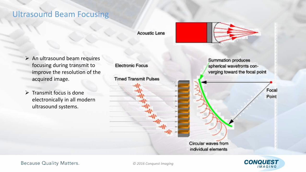
An ultrasound beam requires focusing during transmit to improve the resolution of the acquired image.
Transmit focus is done electronically in all modern ultrasound systems.
Ultrasound Beam Focusing

© 2016 Conquest Imaging
The timing of the transmit pulses to each element is aligned so that the wave fronts from all the piezoelectric elements arrive at a selected spatial point at the same time.
This is accomplished by introducing a curve into the timing delays, whose center is the desired focal point.
Electronic focus is the same as using an acoustic lens; however, using electronic instead of physical focus allows the transmit focal point to be changed simply by changing the delay pattern.
Ultrasound Beam Focusing

© 2016 Conquest Imaging
The wave fronts propagate once they leave the transducer, and there is no way to alter the transmit energy pattern.
During the receive mode, dramatic enhancement of the focal capabilities of the system can be achieved.
As the ultrasound wave strikes various interfaces/tissues in the body, some of its energy is transmitted and some is reflected toward the transducer.
Ultrasound Receive Focusing
Reflected Energy
Transducer

© 2016 Conquest Imaging
During the receive phase, an electronic lens is continuously reshaped as the focal point moves away from the array at half the velocity of ultrasound to maintain precise focus along each scan line.
“Receive Dynamic Focus” maintains superior resolution throughout the ultrasound image, and the resolution is not limited by a small transducer aperture (number of active elements used to generate one scan line) or by a fixed focal zone.
Receive Dynamic Focus
Dynamic focus is achieved by controlling the delay of each signal arriving at each element through each channel, such that only signals from the computed sliding focal point arrive at a final summation point at the same time.

© 2016 Conquest Imaging
Dynamic focus is achieved by controlling the delay of each signal arriving at each element through each channel, such that only signals from the computed sliding focal point arrive at a final summation point at the same time.
Receive Dynamic Focus

© 2016 Conquest Imaging
The ultrasound system applies high voltage pulses to the transducer elements. This produces ultrasound waves that travel through the human body and interact with various organs.
The reflected energy travels back to the transducer where each of its elements acts as a receiver. The reflected ultrasound energy is converted into tiny electrical signals.
The ultrasound system processes these signals to produce an image that represents these reflections on the monitor.
Gray-scale Imaging / 2D Imaging Dynamic Focus

© 2016 Conquest Imaging
When an ultrasound wave travels through a medium, it causes expansion and compression of the medium.
Ultrasound waves interact with tissue in these five basic manners:
Transmission
Reflection
Scattering
Attenuation
Refraction
Tissue Interactions

© 2016 Conquest Imaging
Transmission: Sound energy transmitted from the transducer enters the body.
Some of the ultrasound energy continues deeper into the body.
These waves will reflect from deeper tissue structures.
Tissue Interactions
Transducer

© 2016 Conquest Imaging
Reflection: This is the source for the ultrasound image.
Some waves reflect off different tissues and return back to the ultrasound transducer.
Tissue Interactions
Transducer

© 2016 Conquest Imaging
Scattering:
The signal that reaches the transducer is a much weaker than the transmitted one and is typically 100-1000 (40 - 60 dB) less than the transmitted signal.
Most scattering occurs with red blood cells, which have a width of 7-10 µm, which is 20 times smaller than the ultrasound wavelength (0.2 to 1 mm).
Tissue Interactions

© 2016 Conquest Imaging
Attenuation: is the decreasing intensity of a sound wave as it passes through a medium. It is the result of energy absorption of tissue, as well as reflection and scattering that occurs between the boundaries of tissue with different densities.
Tissue absorption of sound energy contributes most to the attenuation of an ultrasound wave in tissues.
The deeper the ultrasound wave travels in the body, the weaker it becomes.
Deep reflections require extra amplification when used to build an ultrasound image.
Tissue Interactions

© 2016 Conquest Imaging
The American Institute of Ultrasound in Medicine (AIUM) guidelines for limits below which ultrasound clearly has been demonstrated to be safe:
A diagnostic exposure that produces a 1°C or less temperature elevation above normal.
An exposure intensity less than 1 W/cm2 for focused ultrasound beams.
Diagnostic ultrasound systems generally have outputs ranging from 10 mW/cm2 for imaging to as high as 430 mW/cm2 for pulsed Doppler ultrasound. There has been no evidence to date to suggest adverse effects at these ultrasonic outputs.
Ultrasound Attenuation Effects
Ultrasound attenuation by tissue produces heat energy and this property is used for some non-diagnostic treatments.
Extreme prolonged exposure without movement of the transducer could cause harm to tissues.
© 2016 Conquest Imaging
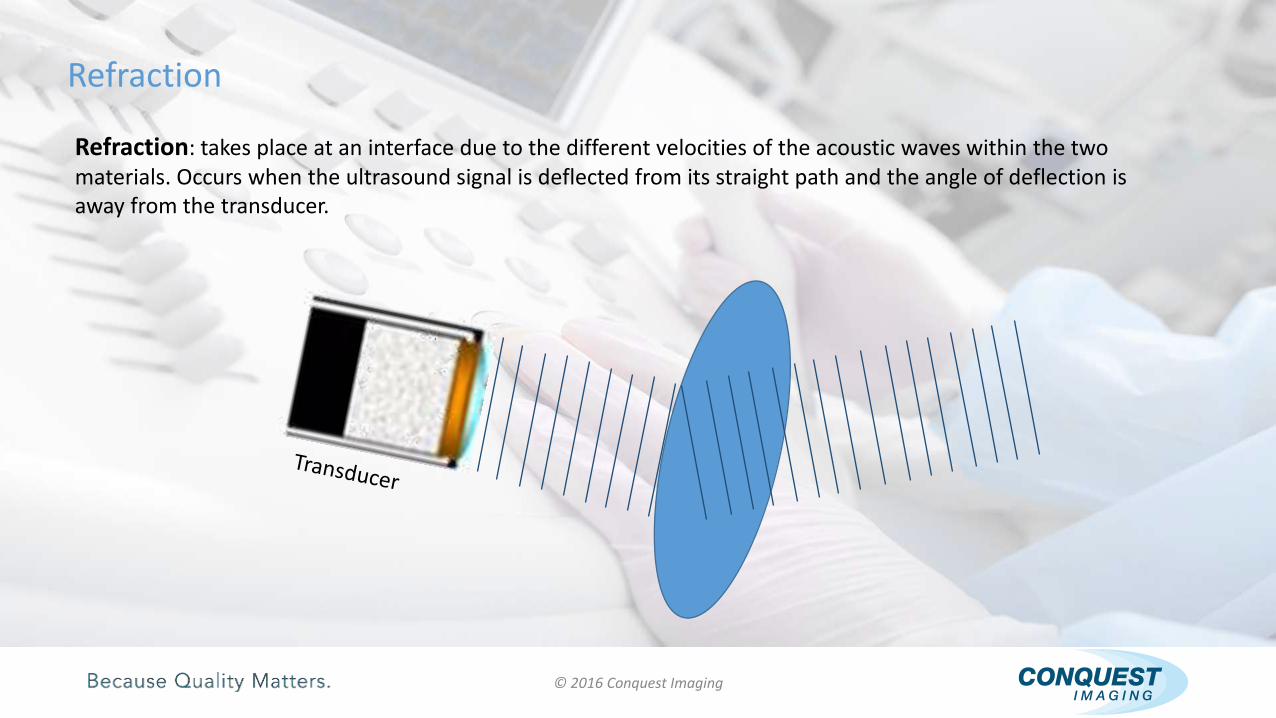
Refraction: takes place at an interface due to the different velocities of the acoustic waves within the two materials. Occurs when the ultrasound signal is deflected from its straight path and the angle of deflection is away from the transducer.
Refraction

© 2016 Conquest Imaging
Refraction: Ultrasound waves are only refracted at a different medium interface of different acoustic impedance.
Refraction
Refraction allows enhanced image quality by using acoustic lenses.
Refraction can result in ultrasound double-image artifacts.

© 2016 Conquest Imaging
Image Quality
The following parameters influence ultrasound image quality:
Detail/Spatial Resolution: The ability to distinguish small structures (axial and lateral resolution).
Image Uniformity: Comparable detail and contrast throughout the image.
Contrast resolution: The ability to differentiate different tissue types without introducing noise.
Temporal Resolution/Frame rate: The rate to acquire frames and display them.
Dynamic range: Largest and smallest signals acquired and displayed.
Spatial Discrimination: The ability to limit artifacts and reflections from other locations.
Bandwidth: The system ability to reproduce signals appropriately.

© 2016 Conquest Imaging
Image Resolution
Axial Resolution:
Axial resolution is the minimum separation between two structures the ultrasound beam can distinguish parallel to the beam path.
Axial Resolution
The ability to separate structures parallel to the ultrasound beam

© 2016 Conquest Imaging
Image Resolution
Would be seen as one structure
Would be seen as two structures
Would be seen as one structure
LateralResolution
Linear Array
Lateral Resolution: Lateral Resolution is the minimum separation from other tissue the ultrasoundbeam can distinguish in a plane perpendicular to the ultrasound beam.
© 2016 Conquest Imaging
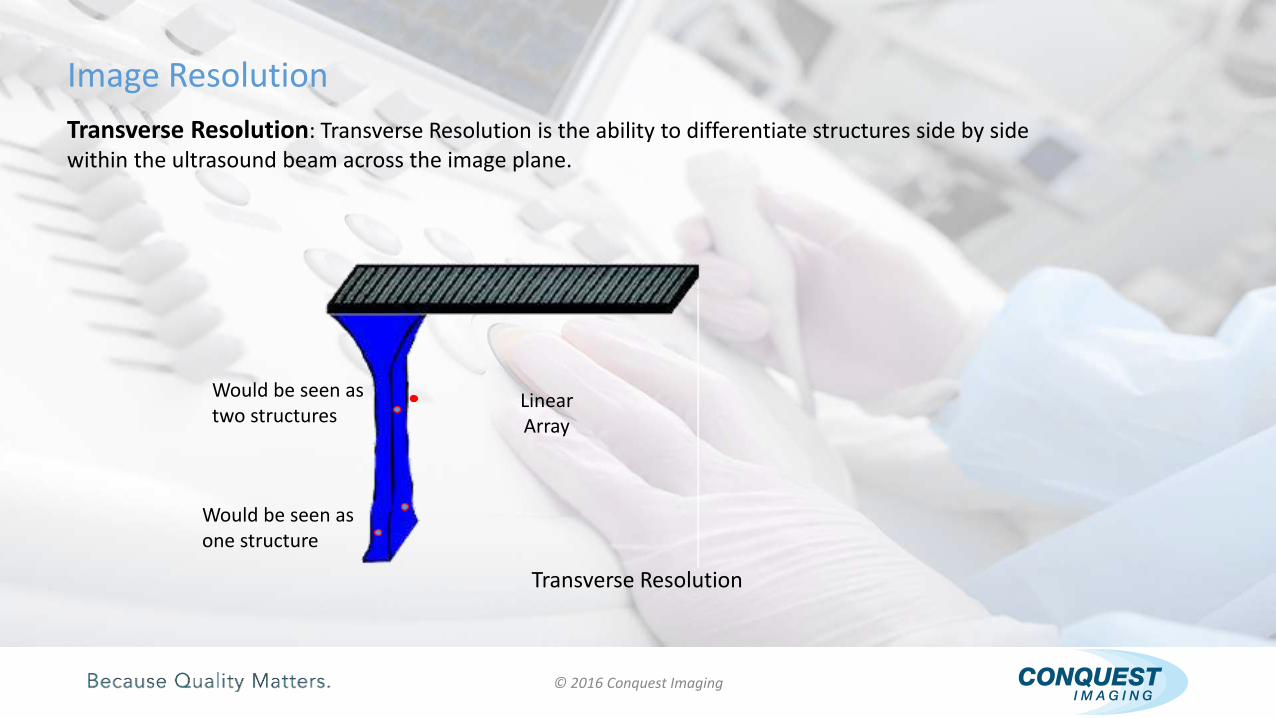
Image Resolution
Would be seen as two structures
Would be seen as one structure
Linear Array
Transverse Resolution
Transverse Resolution: Transverse Resolution is the ability to differentiate structures side by side within the ultrasound beam across the image plane.

© 2016 Conquest Imaging
Image Resolution
Linear Array
Contrast Resolution: The ability to differentiate different tissue types without introducing noise. The use of a tissue mimicking phantom allows the user to qualify the contrast resolution of the ultrasound system. The system should be able to resolve structures with contrast level differences as low as 3 dB.

© 2016 Conquest Imaging
Image Resolution
Contrast Resolution:

© 2016 Conquest Imaging
Ultrasound Modes
This module provides an overview of ultrasound modes. After completing this module you will be familiar with the different modes of ultrasound and their appropriate uses.
Doppler Ultrasound
Pulsed Wave Doppler (PW)
AUX Continuous Wave Doppler (CW)

© 2016 Conquest Imaging
Doppler Ultrasound
What is the Doppler Effect?
A change in the observed frequency of a wave, as of sound or light, occurring when the source and observer are in motion relative to each other, with the frequency increasing when the source and observer approach each other and decreasing when they move apart. Also called Doppler Shift.
© 2016 Conquest Imaging
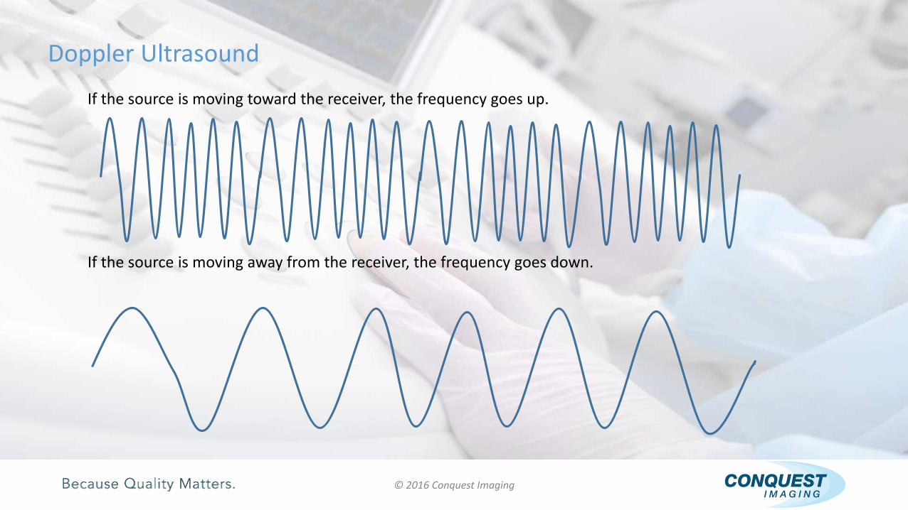
Doppler Ultrasound
If the source is moving toward the receiver, the frequency goes up.
If the source is moving away from the receiver, the frequency goes down.

© 2016 Conquest Imaging
Doppler Use in Ultrasound
Doppler is used to evaluate blood flow where the ultrasound transducer is both the source and receiver of ultrasound waves.
The blood flow is in motion relative to the imaging transducer.

© 2016 Conquest Imaging
Pulsed Wave Doppler (PW)
The system produces short bursts of ultrasound waves (TX) and listens to the reflected waves (RX) in between.
The same crystals are being used for transmit and receive of the ultrasound waves.
It uses the same pulse-echo technique in 2D imaging mode.
TX RX TX RXTXRX TX

© 2016 Conquest Imaging
Pulsed Wave Doppler (PW)
PW allows us to sample at a specific depth along the Doppler line. This is represented by the sample volume ( Gate )
The velocity that PW can represent is limited.
Spectral Data is a representation of
the blood flow
© 2016 Conquest Imaging
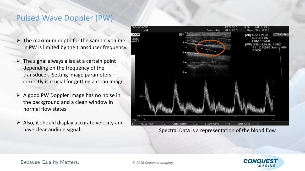
Pulsed Wave Doppler (PW)
The maximum depth for the sample volume in PW is limited by the transducer frequency.
The signal always alias at a certain point depending on the frequency of the transducer. Setting image parameters correctly is crucial for getting a clean image.
A good PW Doppler image has no noise in the background and a clean window in normal flow states.
Also, it should display accurate velocity and have clear audible signal. Spectral Data is a representation of the blood flow

© 2016 Conquest Imaging
Pulsed Wave Doppler (PW)
Blood flow is towards the transducer
Velocity
Time
Spectral data in a PW image mode provides information about the direction, velocity and quality of the flow.
© 2016 Conquest Imaging
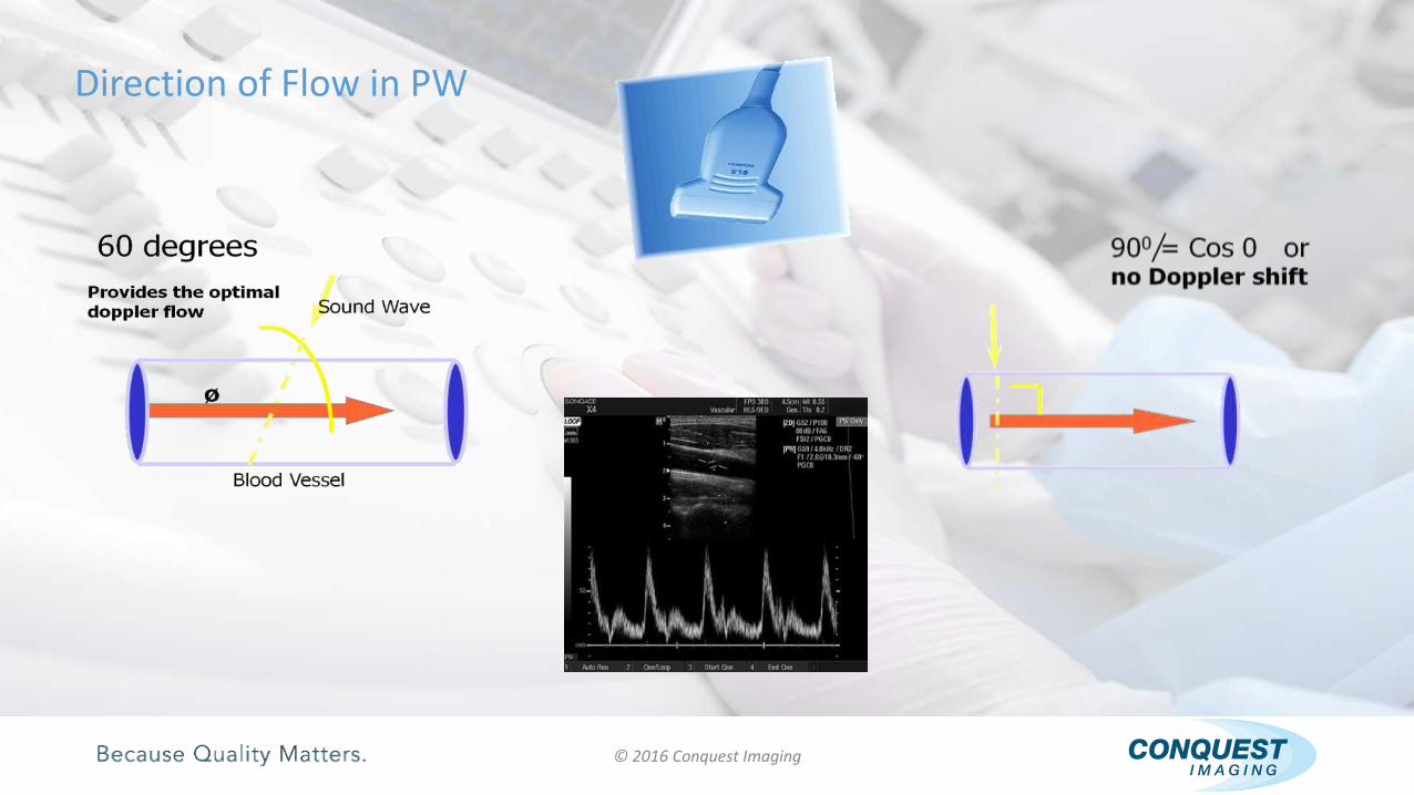
Direction of Flow in PW

© 2016 Conquest Imaging
Aliasing
Aliasing happens when Doppler sample rate is not adequate enough for high frequency shift.
When the velocity of the flow is too high to be displayed in the spectral window, the peaks are cut off and displayed below the baseline.

© 2016 Conquest Imaging
Aliasing
Aliasing:
Mirroring:

© 2016 Conquest Imaging
AUX Continuous Wave Doppler (AUX CW)
Uses different piezoelectric elements to send and receive ultrasound waves.
One element constantly sends ultrasound waves of a single frequency while another constantly receives the reflected waves.
No B-mode image is acquired or displayed.

© 2016 Conquest Imaging
AUX Continuous Wave Doppler (AUX CW)
AUX CW Doppler can display flow at any velocity without aliasing.
AUX CW Doppler cannot position the sample to listen at a specific depth.
Samples everything along the Doppler line.

© 2016 Conquest Imaging
Steered CW Doppler (CW)
This imaging mode is available on cardiac systems.
It utilizes an imaging transducer (phased array) to generate a CW Doppler image.

© 2016 Conquest Imaging
Color Doppler Ultrasound
Color Doppler provides a method to visualize blood flow and differentiate it from surrounding tissue.
It provides information about the presence of blood flow, its direction and speed.
Color Doppler utilizes pulse-echo Doppler flow principles to generate a color image.

© 2016 Conquest Imaging
Color Doppler Ultrasound
This color image is superimposed on the 2D grayscale image.
The red and blue colors provide an indication of the flow velocity and direction.

© 2016 Conquest Imaging
Color Doppler Ultrasound
The upper part of the color bar represents flow toward the transducer.
The bottom part of the color bar represents flow away from the transducer.

© 2016 Conquest Imaging
Color Doppler Ultrasound
54
The color box in Color Doppler imaging mode must approach the vessel or heart chambers at an angle other than 90 degrees.
Otherwise, based on Doppler principles there will be little or no color at perpendicular incidence.

© 2016 Conquest Imaging
Velocity of Flow in Color Doppler UltrasoundColor Doppler is different from PW or CW because it provides an estimation of the average velocity using a technique called “Autocorrelation.”
Every reflected echo is correlated with the corresponding echo from the previous pulse to determine the motion that took place during that pulse.

© 2016 Conquest Imaging
Velocity of Flow in Color Doppler Ultrasound
The shade of the color determines the velocity of the flow.
For both red and blue colors, the darker the shade, the slower the flow. And, the lighter the shade, the faster the flow.
© 2016 Conquest Imaging
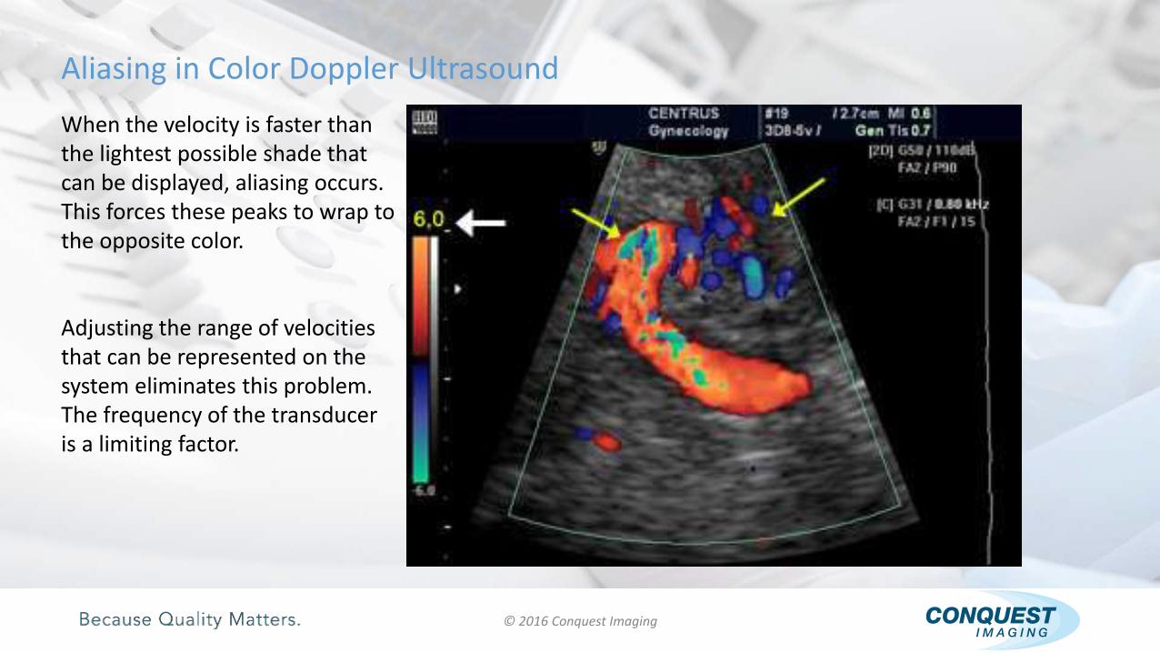
Aliasing in Color Doppler Ultrasound
When the velocity is faster than the lightest possible shade that can be displayed, aliasing occurs. This forces these peaks to wrap to the opposite color.
Adjusting the range of velocities that can be represented on the system eliminates this problem. The frequency of the transducer is a limiting factor.
© 2016 Conquest Imaging
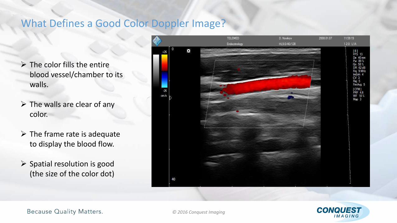
What Defines a Good Color Doppler Image?
The color fills the entire blood vessel/chamber to its walls.
The walls are clear of any color.
The frame rate is adequate to display the blood flow.
Spatial resolution is good (the size of the color dot)

© 2016 Conquest Imaging
Power Doppler Ultrasound
Power Doppler Imaging (PDI) visualizes the integrated power of the Doppler signal instead of its frequency shift used in Color Doppler Imaging.
PDI does not carry directional or velocity information.
Power Doppler Imaging is also called Color Power Angio (CPA).

© 2016 Conquest Imaging
Passive LPF
TX
Beamformer
(FPGA)
Beamformer
Central
Control Unit
HV MUX/
DEMUX
T/R
Swithces
DAC
ADC
LNA TGCRx Buffer
Amp
Passive LPF
RX
Beamformer
(FPGA)
ADCCW (analog)
Beamformer
Spectral
Doppler
Processing (D-
Mode)
Image &
Motion
Processing (B-
Mode)
Color Doppler
(PW)
Processing (F-
Mode)
Data
Transmission
Audio
Amp
Audio
Output
* Texas Instruments
FET
Driver
Tx Buffer
AmpTransducer
Ultrasound Block Diagram

© 2016 Conquest Imaging
SonoCT Imaging
SonoCT Real-time Compound Imaging technology is a unique approach to overcome the inherent artifacts of conventional ultrasound that compromise image quality.
SonoCT imaging technology uses transmit beam-steering techniques to obtain co-planar, tomographic images from different viewing angles, then combines these micro-angulated images into a single compounded image at real-time frame rates.

© 2016 Conquest Imaging
SonoCT Imaging
Real-time spatial compound imaging (SonoCT) uses electronic beam steering of a transducer array to acquire multiple (3 to 9) overlapping scans of an object from different viewing angles.
The single-angle scans are averaged to form a multi-angle compound image that is updated in real time with each subsequent scan.
Compound imaging shows improved image quality compared with conventional ultrasound, primarily because of reduction of speckle, clutter and other acoustic artifacts.
Early clinical experience suggests that real-time spatial compound imaging can provide improved contrast resolution and tissue differentiation that is beneficial for imaging the breast, peripheral blood vessels and musculoskeletal injuries.

© 2016 Conquest Imaging
SonoCT Imaging
SonoCT imaging enables clinicians to acquire up to nine times more tissue information than the orthogonal beams used in conventional ultrasound, without any unusual manipulation of the transducer and without sacrificing frame rates.
SonoCT reduces angle-generated and speckle noise artifacts.
Structures with curved and irregular borders are more readily visualized.
Contrast resolution is improved and tissue margins are more discernable.
This powerful imaging technology is available on linear, curved and volumetric array transducers.
SonoCT produces images superior to conventional imaging in up to 94% of patients.

© 2016 Conquest Imaging
Harmonic Imaging
It’s an ultrasound imaging method in which the higher harmonic echoes (usually the second harmonic) of the fundamental (first harmonic) transmitted frequency are selectively detected and used for imaging.
Simulated beam profiles from the fundamental up to thefifth harmonic for a focused single element transducer.

© 2016 Conquest Imaging
Harmonic Imaging
The higher harmonics may have been created by non-linear scattering, e.g. from gas micro-bubbles or by non-linear propagation of the ultrasound pulse.
A large transducer bandwidth is needed for harmonic imaging since the receiver center frequency must be set to twice the center frequency of the transmitted pulse.
Ignoring original transmitted signal and receiving 4 MHz signal

© 2016 Conquest Imaging
Harmonic Imaging
When harmonic B-mode imaging is used to improve image quality and contrast resolution of tissues, the technique is called Tissue Harmonic Imaging (THI).
When harmonic Doppler ultrasound is used with micro-bubble contrast media (ultrasound contrast medium), the purpose is to improve detection of flow in small vessels by selectively enhancing the Doppler signal from blood and at the same time suppressing the echoes from surrounding tissue.

© 2016 Conquest Imaging
Panoramic Imaging
Panoramic Imaging is a feature of most contemporary ultrasound systems.
It is an imaging process that produces a panoramic image using conventional transducers and provides both qualitative and quantitative information.
Panoramic imaging broadens the scope of spatial relationships, thereby sequentially aligning individual images in their anatomical context.
Panoramic imaging has the ability to display an entire abnormality and show its relationship to adjacent structures on a single static image.

© 2016 Conquest Imaging
Panoramic Imaging
When producing a panoramic image, the transducer needs to be moved smoothly and in a precise direction.
If the object scanned is off plane or off the desired path, forward motion is discontinued and orientation can be corrected.
Image registration stops if the transducer is stationary.
Once the region of interest has been scanned, the panoramic image is saved and can be viewed on the monitor.

© 2016 Conquest Imaging
3D Ultrasound Imaging
In 3D mode the ultrasound waves are sent at different angles. The returning echoes are processed by the ultrasound system to reconstruct a three dimensional volume image of the internal organs. 3D ultrasound images allow us to see width, height and depth but no real time movement.

© 2016 Conquest Imaging
3D Ultrasound Imaging
3D ultrasound is a series of 2D images, rendered by the ultrasound system. The transducer sweeps left and right, collecting a series of 2D images.
“Surface rendering” allows for this series of images to be digitally interpreted by the system and displayed on the monitor.

© 2016 Conquest Imaging
Real Time 3D or 4D Ultrasound Imaging
Real-Time 3D or 4D imaging provides instant three dimensional images live. These images allow us to see width, height, depth and real-time movement.
This image can be captured using 3D matrix array transducers. Also, they can be generated using 3D mechanical array transducers.
Images shown are generated using 3D mechanical array transducers

© 2016 Conquest Imaging
Real Time 3D Ultrasound Imaging
Real-time 3D imaging is sometime called 4D imaging.
Recent advancements in computer technology and software engineering make 4D ultrasound imaging possible. Images shown below were generated using 3D matrix array transducers

Ultrasound System Blocks
© 2016 Conquest Imaging
This module covers the basic building blocks of any ultrasound system followed by some examples of various systems. Building Blocks of a Diagnostic Ultrasound System

Front End, Scanner, Coherent Image Former, or Acquisition Subsystem
Back End, Scan Converter, DIMAQ Workstation, or Platform Subsystem
Power Supply Subsystems – Low voltage and High Voltage Power Supplies
Operating System (OS) and Ultrasound Application Software
Ultrasound Transducers
User Interface or Control Panel
Display Monitor – LCD or CRT based
© 2016 Conquest Imaging
Building Blocks of a Diagnostic Ultrasound System
© 2016 Conquest Imaging
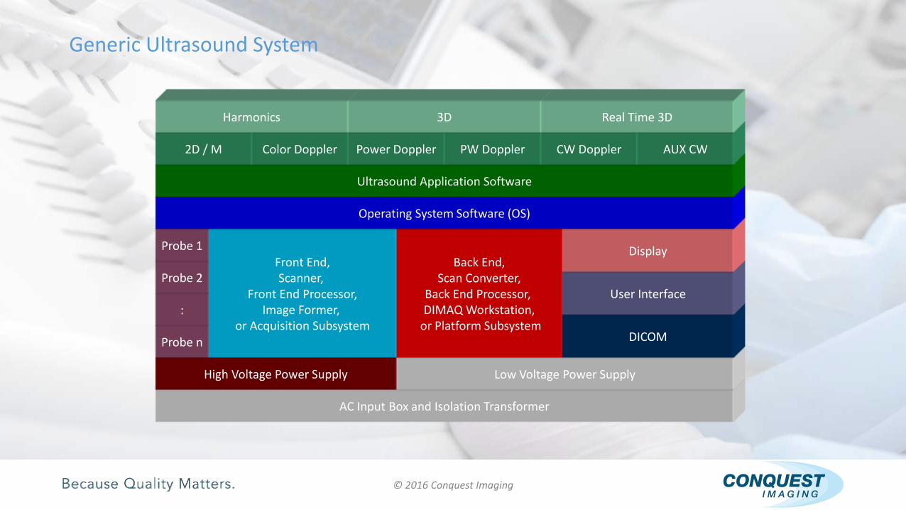
Generic Ultrasound System
AC Input Box and Isolation Transformer
High Voltage Power Supply Low Voltage Power Supply
Probe n
:
Probe 2
Probe 1Front End,Scanner,
Front End Processor,Image Former,
or Acquisition Subsystem
Back End,Scan Converter,
Back End Processor, DIMAQ Workstation,
or Platform SubsystemDICOM
User Interface
Display
Operating System Software (OS)
Ultrasound Application Software
2D / M Color Doppler Power Doppler PW Doppler CW Doppler AUX CW
Harmonics 3D Real Time 3D

© 2016 Conquest Imaging
Probe Interface
Transmitter
Receiver
Beam former
Front End Controller
Probe Interface
Transmitter
Receiver
Beam Former
Front EndController
A generic front end contains the following components:
Front End subsystem

© 2016 Conquest Imaging
Back End Subsystem
A generic back end contains the following components:
System Master Controller
2D/M Signal Processor
PW/CW/Color Doppler Signal Processor
Image Memory & Video Layout
Video Processor
Peripheral Interface
PW/CW/ColorDoppler
Processor
2D/M Processor
ImageMemory
PeripheralInterface
VideoProcessor
System MasterController

© 2016 Conquest Imaging
Modular Block Diagram
AC Input Box and Isolation Transformer
High Voltage Power Supply Low Voltage Power Supply
Probe n
:
Probe 2
Probe 1
ProbeInterface
TransmitterFront End Controller
ReceiverBeam
Former
PW/CW/Color Doppler
Processor
ImageMemory
PeripheralInterface
2D/MProcessor
SystemMaster
Controller
VideoProcessor
DICOM Touch Panel
User Interface
Display
Operating System Software (OS)
Ultrasound Application Software
2D/M Color Doppler Power Doppler PW Doppler CW Doppler AUX CW
Harmonics 3D Real Time 3D

© 2016 Conquest Imaging
Front End Interconnections
Probe Interface
Receiver
Transmitter
Front EndController
Beam Former
Interface with the Back End
High VoltagePower Supply
HV TX Pulses
(-100/+100 V)
Ultrasound Signal
Multi Channels Ultrasound Signal (2D/M/Color/PW
Modes)
Programmable HV Output
HV Power Supply Control Signals
Line
Image
Ultrasound
Signal
Control Signals
HV Power Supply Input Voltages
TX/RX Signals
Front End Power from Main Power
Supply

© 2016 Conquest Imaging
Back End Interconnections
PW/CW/Color
DopplerProcessor
ImageMemory
SystemMaster
ControllerInterface with Front End
2D/MMode
Processor
VideoProcessor
PeripheralInterface
Low VoltagePower Supply
Ultrasound Signal (2D/M/Color/PW/CW Modes)
Ultrasound
Signal
Color/PW/
CW Mode
2D/M Mode
Video
Signal
Video Signal
Power to HV Power SupplyPower to all
Back End modules
Power to all Front End modules
Control
Signals

© 2016 Conquest Imaging
Four Channel Front End
HV Switchers
Frame 1
Linear Array
Probe
RX Amp
RX Amp
RX Amp
RX Amp
TX Amp
TX Amp
TX Amp
TX Amp
Active TX
Channels
RX Focus Pattern
Ch1 to 4
Transmitter
Receiver
TX Focus Pattern
Ch1 to 4
HV Pulses
A/D Converter
Data for 1st
Vertical Line
Control Signals from Back End
Line
1
Line
13
Front End Control
4 Channel Ultrasound Front EndInterfaced with a Linear Array Probe
Active RX Channels

© 2016 Conquest Imaging
Eight Channel Front EndHV SwitchersActive RX Channels
Active TX Channels
RX Focus
Pattern
Ch1 to 8
Transmitter
Receiver
TX Focus Pattern Ch1 to 8
Front End Control
HV Pulses
A/D Converter
Data for 1st
Image Line
Control Signals from Back End
Line
1
Line
N
Frame 1
RX AmpTX Amp
RX AmpTX Amp
RX AmpTX Amp
RX AmpTX Amp
RX AmpTX Amp
RX AmpTX Amp
RX AmpTX Amp
RX AmpTX Amp
TX Time Delay 8 Channel Ultrasound Front End Interfaced with a Phased Array Probe
Phased Array
Probe

© 2016 Conquest Imaging
RX Dynamic FocusHV Switchers
Active RX Channels
Active TX Channels
RX Focus
Pattern
Ch1 to 4
Transmitter
Receiver
TX Focus Pattern Ch1 to 8
Front End Control
HV Pulses
A/D Converter
Data for 1st
Image Line
Control Signals from Back End
Line
1
Line
N
Frame 1
RX AmpTX Amp
RX AmpTX Amp
RX AmpTX Amp
RX AmpTX Amp
RX AmpTX Amp
RX AmpTX Amp
RX AmpTX Amp
RX AmpTX Amp
Rx Time Delay
Amplitude
RX Dynamic Focus for a Front End interfaced with a Phased Array Probe
Phased Array
Probe
Line 1
Line 2
Line 3
Line N

© 2016 Conquest Imaging
RX Dynamic Focus
Image Line 1
Frame 1
Frame 2
Frame 3
Frame NImage
Memory
Image Line 2
Image Line (X)
Image Line N
Digital Scan
Converter
VideoProcessor
System MasterController
Image Lin
e 1
Image Lin
e 2
Image Lin
e (X)
Image Lin
e N
System
DisplayFrame N-1
Frame 1
Frame N
Frame 1
Basic Back End Processor

© 2016 Conquest Imaging
Power Subsystems
High Voltage Power Supply:
Provides voltages to drive the probe’s elements (array) in the range of +150V/-150V.
Low Voltage Power Supply:
Provides +3.3/+5/-5/+12/-12/+15/-15 VDC to the Back End & Front End subsystems.

Ultrasound System Block Diagrams
© 2016 Conquest Imaging
Acuson Sequoia
GE Voluson 730
GE VIVID7
Philips iU22

© 2016 Conquest Imaging
Acuson Sequoia 512 Ultrasound System

© 2016 Conquest Imaging
Acuson Sequoia 512 Ultrasound System

© 2016 Conquest Imaging
Acuson Sequoia 512 Ultrasound System
APODZ./ DELAY/ GAIN
ACQUISITION BUS
TX APODZ. / DELAY
XDCR
TRANSMIT MULTIPLEXER
RECEIVE
MULTIPLEXER
TX / RX SWITCHING CONTROL
MP
AUX AMP
IMAGE FORMERSubsystem
SEQUOIA 512
MX
RX
LOW NOISE
VARIABLE GAIN
AMP
RX CONTROL
GAIN
SPECTRAL DOPPLER
PROCESSOR
MAINCLOCK
CW/PW
B/M/COLOR
BF
BF
ANALOG TO DIGITAL
CONVERTERBFP SUMMING
ANALOG TO DIGITAL
CONVERTERBFP SUMMING
TX-A
TX-B
H.V. Output Amp
DIGITAL TO ANALOG
CONVERTER
PROGRAMABLE WAVE
GENERATOR
H.V. Output Amp
DIGITAL TO ANALOG
CONVERTER
PROGRAMABLE WAVE
GENERATOR
RI
89

© 2016 Conquest Imaging
Acuson Sequoia 512 Ultrasound System
B / M DATA
F DATA
ACQUISITION CONTROL BUS
CN BDM
CSD
SYSTEM CENTRAL BUS
DIMAQ Integrated
Workstation
SEQUOIA 512
ACQUISITION CONTROL
FOCUS CONTROL
FILTERING
SUMMING
DMA
B/M
COLOR
DOPPLER
DATA
COLOR
SPECTRAL
AUDIOSYSTEM
DATA MEMORY
B/M ACQ. & PRE-
PROCESSING
SYSTEM DATA
MANAGER

© 2016 Conquest Imaging
Acuson Sequoia 512 Ultrasound System
VIDEO
DISPLAY
BUFFER
IMAGE
RECONSTRUCTION
SYSTEM SUPERVISORY PROCESSOR
RDP
IOV
I/O
PROCESSOR
VIDEOSTANDARDSCONVERTER
B/M/D/F/VCR DATA
AUDIO
AUDIO/ VCR PLAYBACK / PHYSIO
ETHERNET
JPEG
COPMRESSION/
DECOMPRESSIOE
PROGRESSIVE
VIDEO
PIC
SCSI
HD
MO
INTERNET CONNECTION
AEGIS
VCR PLAYBACK
SYSTEM AUDIO
PHYSIO
FPP
SWITCH ASSY
DISPLAY
USER INTERFACE
PPS
H.V.
MDI
POWER SUBSYSTEM
SEQUOIA 512
SPEAKERS
FIZ Module
VCR
Color Printer
Fan Tray

© 2016 Conquest Imaging
GE Voluson 730 Expert/Pro Ultrasound System

© 2016 Conquest Imaging
GE Voluson 730 Expert/Pro Block Diagram
CPK: Motherboard of GEF Module
CPN:
Main Power Supply Module
CRW:
CW
Doppler
Board
(Optional)
CRS: (BT03+)
This board replaces:
CPG, CPF,
CPC & CCM
Boards in
BT02 Expert
/Pro
CPR: Beamformer
32 CPD sub board
CPZ: Cover Board
CPV/CPU:
Probe Board
Provides
three probe
connectors
and an
optional
CW
connector
CPP:
Power Supply
Provides
+3.3/+5/+12/
+15/-15
+Fan(17-24)
TX Power
(-90/+90)
DC voltages
CPM:
PC Motherboard
CKV: Video Card-DMA Controller
CPE: Backplane
SBC: Single Board Computer
DVI:
Card (Expert only)
59 VDC CPE CPP
110 V AC
Front End Back End
H.D.
v
Monitor
User
Interface
CCFCPH
CPY
Standby Switch
GEM
59 VDC

© 2016 Conquest Imaging
GE Vivid 7 Ultrasound System

© 2016 Conquest Imaging
GE Vivid 7 Ultrasound System
TXPower Supply
DCPower Supply
Display
Patient I/O
Internal I/O
AC Controller
TransformerBox
UPS
AC Input
Probe
BackEnd
Processor
FrontEnd
Processor
OperatorPanel
ExternalI/O

© 2016 Conquest Imaging
GE Vivid 7 Ultrasound System
RX128
Relay
Board
TX128
BF64
BF64
FEC RFT SDP IMP
XD Bus Board
XD Bus Board
Backplane
Digital Signal Processors Subsystem
Pipe Link

© 2016 Conquest Imaging
Philips iU22 Ultrasound System

© 2016 Conquest Imaging
Philips iU22 Ultrasound System
PSA
CB3
CB2
CB0
CB1
Scanhead Select
Acq Frontplane
NA I
M
FEC
Transducer
Platform Power Supply(PPS)
Acquisition Power Supply(APS)
AC Try
Power System & Battery Controller (PSBC)
Includes HV Switcher Function
DebugPort
HostUMB
DSC
HD0
UAVIO
HD1
HD2
USB
Touch Panel
Control Panel DVD Drive
Speakers
BypassPort
RFA & RFB
Control
PCI-E
PCI-E
DVI-D Video, 20 Inch Wide Screen
Signal and PowerDistribution (SPD)
OEMs
USBx6 to OEMs
CPC CPM

© 2016 Conquest Imaging
Philips iU22 Ultrasound System

© 2016 Conquest Imaging
Glossary of Acronyms
AC – Alternating CurrentASIC – Application Specific Integrated CircuitADC – Analog to Digital Converter ATX – Advanced Technology eXtendedBF – Body FloatingCF – Cardiac FloatingCLA – Curved Linear Array (transducer)CPA – Color Power AngioCW – Continuous Wave (transducer)CMOS – Complementary Metal OxideDAC – Digital to Analog ConverterDGC – Depth Gain Control (same as TGC)DICOM – Digital Imaging and Communications in MedicineDNS – Domain Name ServerECG – ElectrocardiogramESU – Electo Surgical UnitFOV – Field of View
FPGA – Field Programmable Gate ArrayHV – High VoltageLNA – Low Noise AmplifierMRI – Magnetic Resonance ImagingPDI – Power Doppler Imaging PWT – Pulsed Wave TransducerPZT – Lead Zirconate Titanate (P=Pb)RIS – Radiology Information SystemRF – Radio FrequencyRLE – Run Length EncodingROI – Region of InterestTGC – Time Gain Control or Time Gain Compensation

© 2016 Conquest Imaging
GlossaryAcoustic energy – The amount of heat generated by the transmission of ultrasound. It is measured in joules.Acoustic power – The amount of acoustic energy generated per unit time. It is measured in watts. The biological effects of ultrasound in terms of power are in the milliwatt range.Acoustic output power – The rate at which acoustic energy leaves the transducer.Acoustic intensity – The acoustic power per unit cross-sectional area of the pulse. It is measured in watts per meter squared (W/m2) or in milliwatts per centimeter squared (mW/cm2).Apodization – A weighting function used as means of reducing side lobes in the beam.Application Entity – A node in a DICOM network.Axial resolution – Is also known as longitudinal resolution or azimuthal resolution is resolution in the direction parallel to the ultrasound beam. The resolution at any point along the beam is the same; therefore axial resolution is not affected by depth of imaging.Back End – System block on the user interface side that contains master controller, signal processing, image memory and video layout, peripheral and user interface.Beamforming – A common signal processing technique used to enable directionally or spatially selected signals to be sent or received from sensor arrays.B Mode – Brightness Mode Brightness Mode is the default mode that comes on when any ultrasound / echo machine is turned on. It is a 2 dimensional cross sectional view of the underlying structures made up of numerous B-mode scan lines.

© 2016 Conquest Imaging
Glossary
Cine – The cine mode is a series of rapidly recorded images taken sequentially and displayed in a dynamic movie display format.Digital Imaging and Communications in Medicine – A medical imaging standard for file format and network communications protocol for file sharing between entities capable of sending and receiving patient data and images in DICOM format.DisplayPort – A digital display interface standard administered by the Video Electronics Standards Association (VESA).Doppler effect – Change in the frequency of a periodic event (such as sound waves) due to a change in distance between the source and the observer.Doppler Range Gating – Range gate circuit only allows Doppler shift data from a user specified area to be displayed as output.Dynamic Host Configuration Protocol – A standardized network protocol used on IP networks for dynamically distributing network configuration parameters. IP addresses and networking parameters are requested automatically from a DHCP server, reducing the need to configure these settings manually.Electromagnetic Interference – (EMI) is when a radio frequency (RF) transmitting device interferes with the operation of another electronic device. In a healthcare environment wireless EMI can cause medical equipment to malfunction.Front End – System block that collects data; probe interface, transmitter/receiver, beamformer, front end controller.Harmonics – Ultrasound method that generates images using twice the frequency of the transmitted sound.

© 2016 Conquest Imaging
GlossaryI2C – Inter-IC bus, a two wire serial bus for communication between integrated circuits. Developed by Philips in the 1980’s it is now an industry standard.In Plane Switching – A type of thin film transistor LCD screen that has particularly good wide viewing angle and accurate color reproduction.Loops – Multiframe objects (e.g. video)M Mode – Motion ModeModality Performed Procedure Step – The modality provides information about a performed study, the number of images that were scanned and the status of the exam. The information is shared between a digital modality and the PACS and RIS.Multiplexing – Multiple signals transmitted over a single medium.Picture Archive and Communications Systems – DICOM Medical imaging storage server that stores images from diagnostic devices such as MRI, ultrasound and X-rays.Phased Array Ultrasound (3D imaging) – Sound waves are transmitted at different angles to obtain image.Physio – Refers to ECG inputs.Protocol Data Units – Message formats exchanged between peer entities within a layer. A PDU consists of protocol control information and user data.PS_ON – Refers to an active low signal used with all ATX and newer power supplies that use 20-24 pin motherboard connector. When high all voltages except 5V stand-by are disabled.Run-Length Encoding – A lossless compression method implemented by specifying the number of times a particular intensity value is repeated.

© 2016 Conquest Imaging
Glossary
Synthetic Aperture – An imaging method that improves resolution and depth of ultrasound images.Time Gain Compensation – Uses an array of sliding tabs which control the gain, which compensates for the difference of the strength of the ultrasound returning from varied distances to make the ultrasound image appear uniformly lit from top to bottom.Thin Film Transistor – A type of LCD display that uses active matrix technology.

© 2016 Conquest Imaging
Thank you for attending!
Question and Answer