type ar auxiliary relay high speed instruction leaflet · 2018-05-09 · ar high speed auxiliary...
TRANSCRIPT

41-759LAR High Speed Auxiliary Relay
The target is reset from the outside of the case by apush-rod located at the bottom of the cover.
The front spring, in addition to holding the target, pro-vides restraint for the armature and thus controls thepickup value of the switch.
3.0 CHARACTERISTICSThe AR unit without a series resistor has a sensitivityof 500 milliwatts. By the proper combination of theAR unit and a series resistor, an optimum speed of 2milliseconds can be obtained for an energy input of10 watts.
Typical operating times and effective contact bounceare outlined in the Tables 1 and 2.
All relays are capable of being energized continu-ously. All high speed relays will pick up at 80% ofrated voltage or less; and drop out at 5% of ratedvoltage or higher.
Relays with delayed dropout are available with a min-imum dropout time of 0.1 second and also availablewith a minimum dropout time of 0.2 seconds.
3.1 CONTACT RATING (Table 3)
Each relay contact is rated 3 amps continuous and30 amps long enough to trip a breaker.
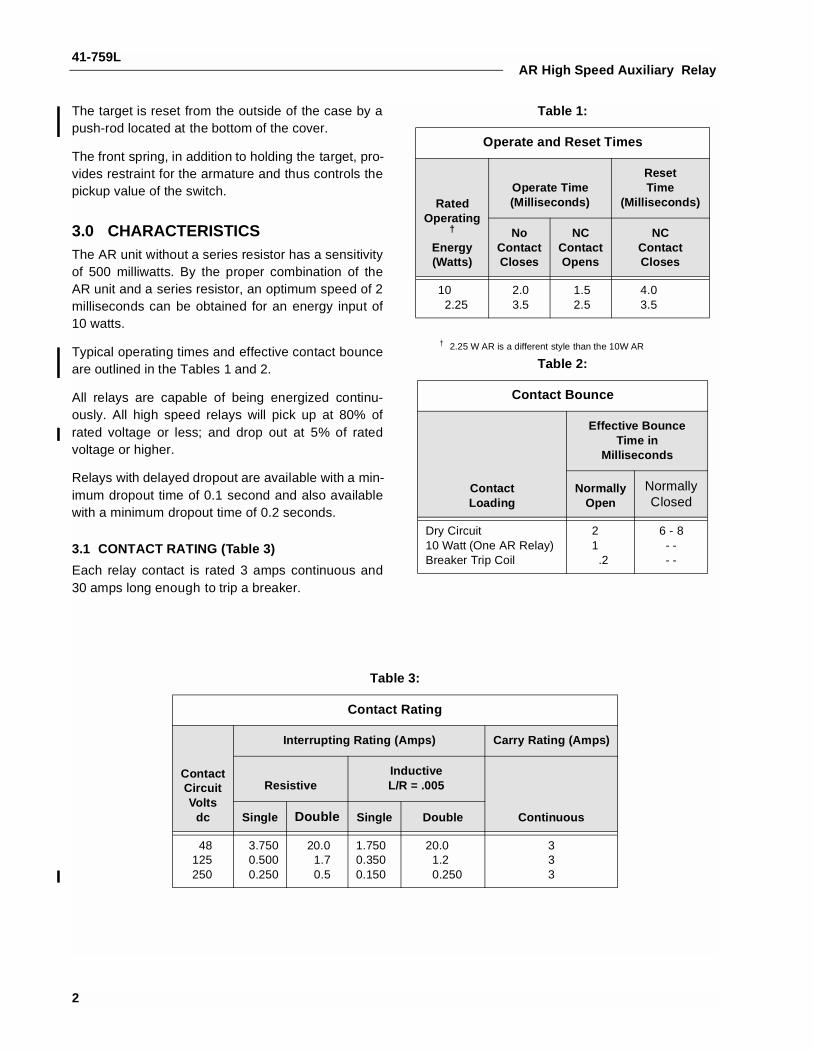
Table 1:
Operate and Reset Times
RatedOperating
†
Energy(Watts)
† 2.25 W AR is a different style than the 10W AR
Operate Time(Milliseconds)
ResetTime
(Milliseconds)
NoContactCloses
NCContactOpens
NCContactCloses
102.25
2.03.5
1.52.5
4.03.5
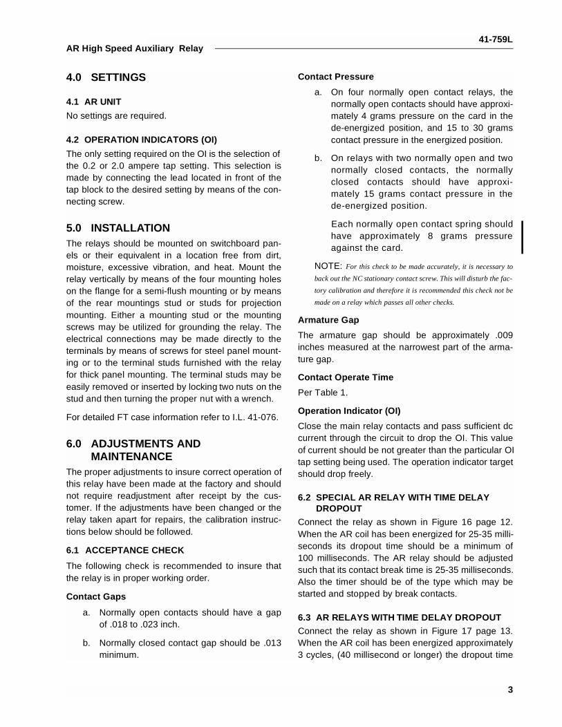
Table 2:
Contact Bounce
ContactLoading
Effective BounceTime in
Milliseconds
NormallyOpen
NormallyClosed
Dry Circuit10 Watt (One AR Relay)Breaker Trip Coil
21
.2
6 - 8- - - -
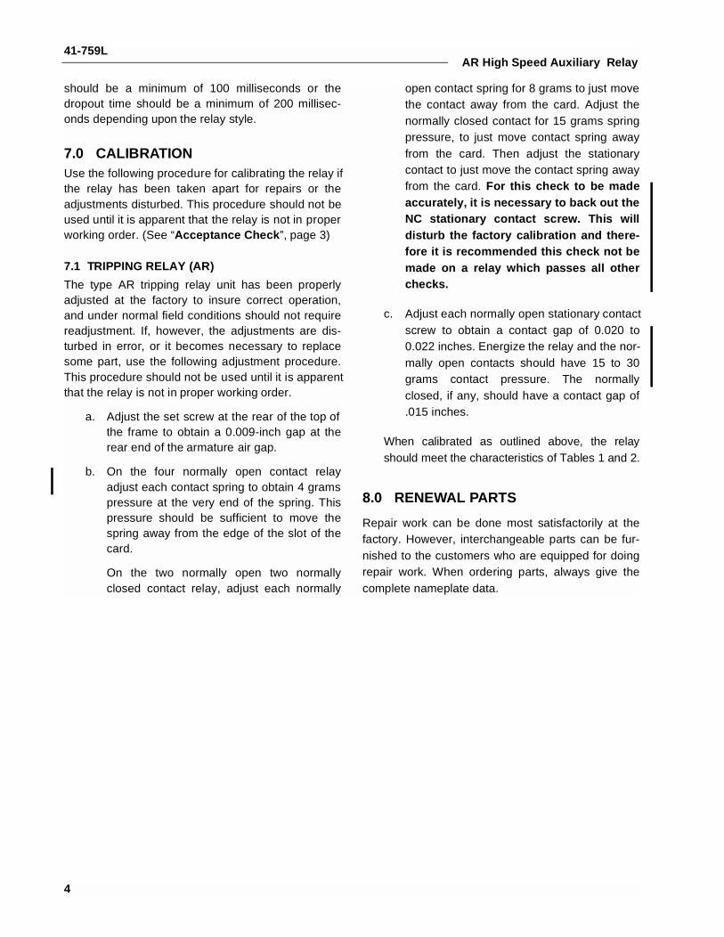
Table 3:
Contact Rating
ContactCircuitVolts
dc
Interrupting Rating (Amps) Carry Rating (Amps)
ResistiveInductiveL/R = .005
ContinuousSingle Double Single Double
48125250
3.7500.5000.250
20.01.70.5
1.7500.3500.150
20.01.20.250
333
2
41-759LAR High Speed Auxiliary Relay
4.0 SETTINGS
4.1 AR UNIT
No settings are required.
4.2 OPERATION INDICATORS (OI)
The only setting required on the OI is the selection ofthe 0.2 or 2.0 ampere tap setting. This selection ismade by connecting the lead located in front of thetap block to the desired setting by means of the con-necting screw.
5.0 INSTALLATIONThe relays should be mounted on switchboard pan-els or their equivalent in a location free from dirt,moisture, excessive vibration, and heat. Mount therelay vertically by means of the four mounting holeson the flange for a semi-flush mounting or by meansof the rear mountings stud or studs for projectionmounting. Either a mounting stud or the mountingscrews may be utilized for grounding the relay. Theelectrical connections may be made directly to theterminals by means of screws for steel panel mount-ing or to the terminal studs furnished with the relayfor thick panel mounting. The terminal studs may beeasily removed or inserted by locking two nuts on thestud and then turning the proper nut with a wrench.
For detailed FT case information refer to I.L. 41-076.
6.0 ADJUSTMENTS AND MAINTENANCE
The proper adjustments to insure correct operation ofthis relay have been made at the factory and shouldnot require readjustment after receipt by the cus-tomer. If the adjustments have been changed or therelay taken apart for repairs, the calibration instruc-tions below should be followed.
6.1 ACCEPTANCE CHECK
The following check is recommended to insure thatthe relay is in proper working order.
Contact Gaps
a. Normally open contacts should have a gapof .018 to .023 inch.
b. Normally closed contact gap should be .013minimum.
Contact Pressure
a. On four normally open contact relays, thenormally open contacts should have approxi-mately 4 grams pressure on the card in thede-energized position, and 15 to 30 gramscontact pressure in the energized position.
b. On relays with two normally open and twonormally closed contacts, the normallyclosed contacts should have approxi-mately 15 grams contact pressure in thede-energized position.
Each normally open contact spring shouldhave approximately 8 grams pressureagainst the card.
NOTE: For this check to be made accurately, it is necessary to
back out the NC stationary contact screw. This will disturb the fac-
tory calibration and therefore it is recommended this check not be
made on a relay which passes all other checks.
Armature Gap
The armature gap should be approximately .009inches measured at the narrowest part of the arma-ture gap.
Contact Operate Time
Per Table 1.
Operation Indicator (OI)
Close the main relay contacts and pass sufficient dccurrent through the circuit to drop the OI. This valueof current should be not greater than the particular OItap setting being used. The operation indicator targetshould drop freely.
6.2 SPECIAL AR RELAY WITH TIME DELAY DROPOUT
Connect the relay as shown in Figure 16 page 12.When the AR coil has been energized for 25-35 milli-seconds its dropout time should be a minimum of100 milliseconds. The AR relay should be adjustedsuch that its contact break time is 25-35 milliseconds.Also the timer should be of the type which may bestarted and stopped by break contacts.
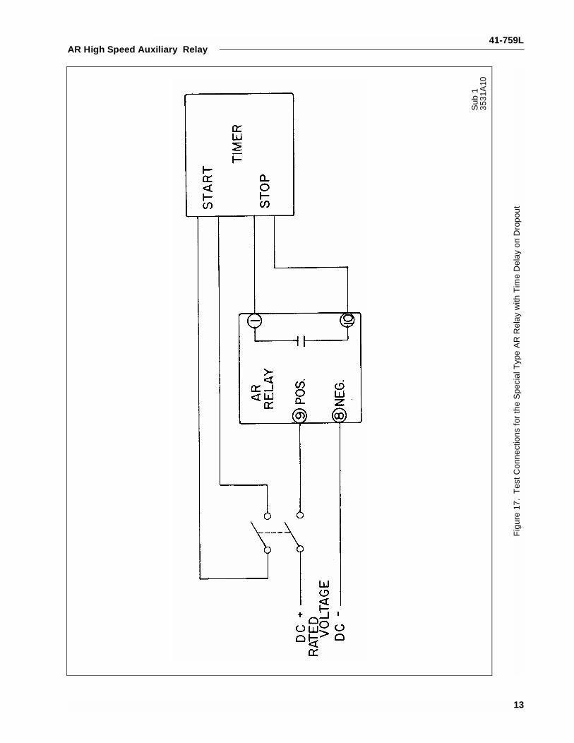
6.3 AR RELAYS WITH TIME DELAY DROPOUT
Connect the relay as shown in Figure 17 page 13.When the AR coil has been energized approximately3 cycles, (40 millisecond or longer) the dropout time
3
41-759LAR High Speed Auxiliary Relay
should be a minimum of 100 milliseconds or thedropout time should be a minimum of 200 millisec-onds depending upon the relay style.
7.0 CALIBRATIONUse the following procedure for calibrating the relay ifthe relay has been taken apart for repairs or theadjustments disturbed. This procedure should not beused until it is apparent that the relay is not in properworking order. (See “Acceptance Check”, page 3)
7.1 TRIPPING RELAY (AR)
The type AR tripping relay unit has been properlyadjusted at the factory to insure correct operation,and under normal field conditions should not requirereadjustment. If, however, the adjustments are dis-turbed in error, or it becomes necessary to replacesome part, use the following adjustment procedure.This procedure should not be used until it is apparentthat the relay is not in proper working order.
a. Adjust the set screw at the rear of the top ofthe frame to obtain a 0.009-inch gap at therear end of the armature air gap.
b. On the four normally open contact relayadjust each contact spring to obtain 4 gramspressure at the very end of the spring. Thispressure should be sufficient to move thespring away from the edge of the slot of thecard.
On the two normally open two normallyclosed contact relay, adjust each normally
open contact spring for 8 grams to just movethe contact away from the card. Adjust thenormally closed contact for 15 grams springpressure, to just move contact spring awayfrom the card. Then adjust the stationarycontact to just move the contact spring awayfrom the card. For this check to be madeaccurately, it is necessary to back out theNC stationary contact screw. This willdisturb the factory calibration and there-fore it is recommended this check not bemade on a relay which passes all otherchecks.
c. Adjust each normally open stationary contactscrew to obtain a contact gap of 0.020 to0.022 inches. Energize the relay and the nor-mally open contacts should have 15 to 30grams contact pressure. The normallyclosed, if any, should have a contact gap of.015 inches.
When calibrated as outlined above, the relayshould meet the characteristics of Tables 1 and 2.
8.0 RENEWAL PARTS
Repair work can be done most satisfactorily at thefactory. However, interchangeable parts can be fur-nished to the customers who are equipped for doingrepair work. When ordering parts, always give thecomplete nameplate data.
4

41-759LAR High Speed Auxiliary Relay
1
4
6
3 52
1.N
orm
ally
cl
osed
st
atio
nary
cont
act s
crew
s2.
Nor
ma
lly
open
st
atio
nary
cont
act s
crew
s
3.L
eaf s
prin
g m
ovin
g co
nta
cts
4.M
ovin
g c
ard
asse
mb
ly5.
Re
lay
coil
6.M
old
ed is
olat
ion
bloc
k
23
6
4
5
1
1.N
orm
ally
cl
osed
st
atio
nary
cont
act s
cre
ws
2.N
orm
ally
op
en
stat
iona
ryco
ntac
t scr
ew
s3.
Mov
ing
Arm
atur
e
4.U
-sha
ped
lam
inat
ed
core
5.A
rma
ture
gap
adj
ustm
ent
set
scre
w6.
Arm
atu
re G
ap
Fig
ure
1.T
ype
AR
Uni
t with
2 M
ake
– 2
Bre
ak C
onta
cts
(Fro
nt V
iew
).F
igur
e 2.
Typ
e A
R U
nit w
ith 2
Mak
e –
2 B
reak
Con
tact
s (S
ide
Vie
w).
5
41-759L
6
AR High Speed Auxiliary Relay
Sub
462
9A49
6S
ub
283
7A11
3
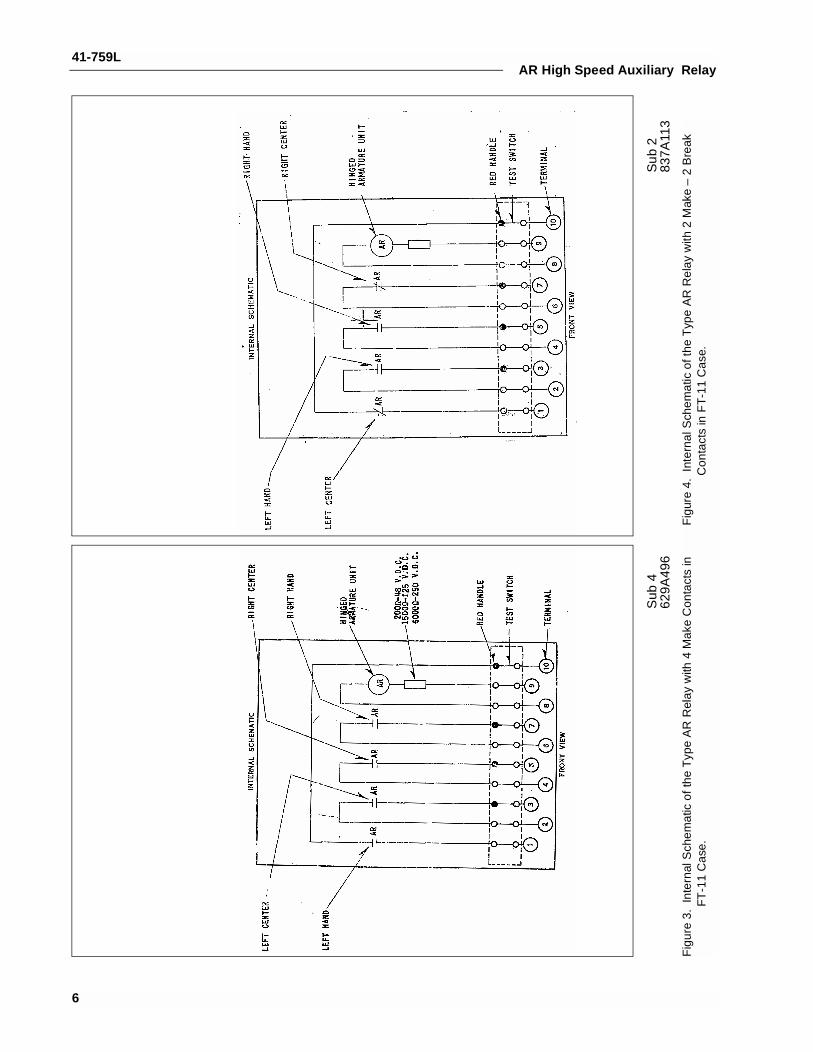
Fig
ure
3.In
tern
al S
chem
atic
of t
he T
ype
AR
Rel
ay w
ith 4
Mak
e C
onta
cts
in
FT
-11
Cas
e.F
igur
e 4.
Inte
rnal
Sch
emat
ic o
f the
Typ
e A
R R
elay
with
2 M
ake
– 2
Bre
ak
Con
tact
s in
FT
-11
Cas
e.
41-759LAR High Speed Auxiliary Relay
*Su
b 5
629
A49
5S
ub 2
762A
529
Fig
ure
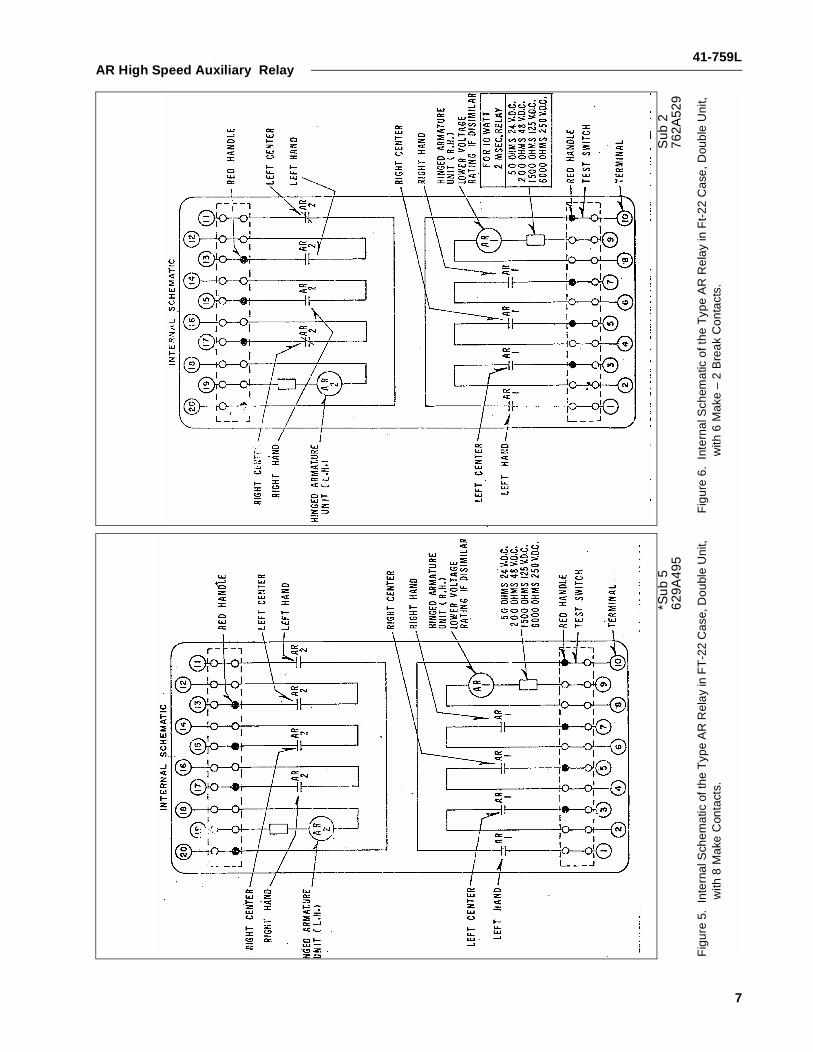
5.In
tern
al S
chem
atic
of t
he T
ype
AR
Rel
ay in
FT
-22
Cas
e, D
oubl
e U
nit,
with
8 M
ake
Con
tact
s.F
igur
e 6.
Inte
rnal
Sch
emat
ic o
f the
Typ
e A
R R
elay
in F
t-22
Cas
e, D
oubl
e U
nit,
with
6 M
ake
– 2
Bre
ak C
onta
cts.
7
41-759L
8
AR High Speed Auxiliary Relay
*Sub
476
2A58
0*S
ub 4
629A
899
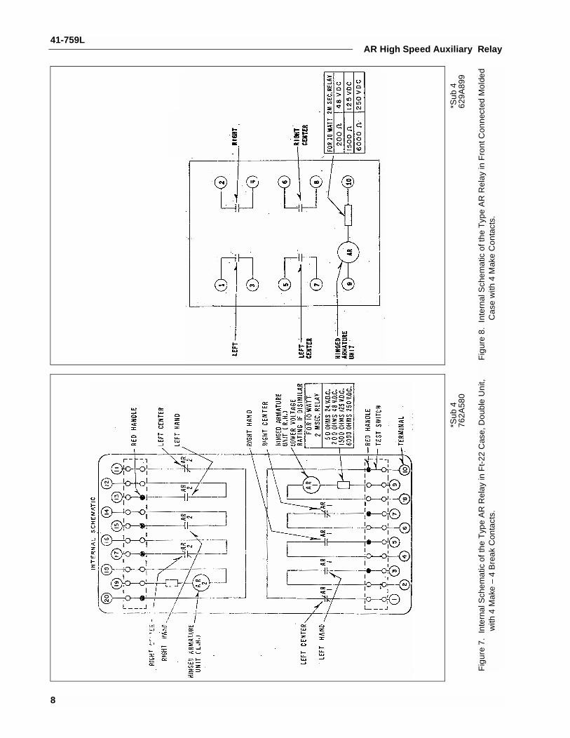
Fig
ure
7.In
tern
al S
chem
atic
of t
he T
ype
AR
Rel
ay in
Ft-
22 C
ase,
Dou
ble
Uni
t, w
ith 4
Mak
e –
4 B
reak
Con
tact
s.F
igur
e 8.
Inte
rnal
Sch
emat
ic o
f the
Typ
e A
R R
elay
in F
ront
Con
nect
ed M
olde
d C
ase
with
4 M
ake
Con
tact
s.
41-759LAR High Speed Auxiliary Relay
*Sub
483
7A11
2S
ub 2
836A
646
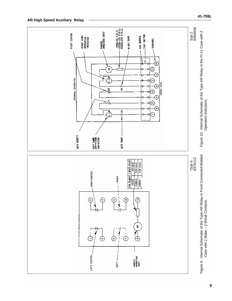
Fig
ure
9.In
tern
al S
chem
atic
of t
he T
ype
AR
Rel
ay in
Fro
nt C
onne
cted
Mol
ded
Cas
e w
ith 2
Mak
e –
2 B
reak
Con
tact
s.F
igur
e 10
.In
tern
al S
chem
atic
of t
he T
ype
AR
Rel
ay in
the
Ft-
11 C
ase
with
2
Ope
ratio
n In
dica
tors
.
9
41-759L
10
AR High Speed Auxiliary Relay
Sub
383
6A91
7S
ub 3
836A
859
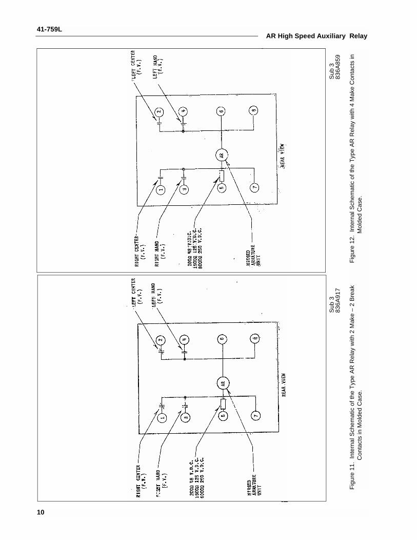
Fig
ure
11.
Inte
rnal
Sch
emat
ic o
f the
Typ
e A
R R
elay
with
2 M
ake
– 2
Bre
ak
Con
tact
s in
Mol
ded
Cas
e.F
igur
e 12
.In
tern
al S
chem
atic
of t
he T
ype
AR
Rel
ay w
ith 4
Mak
e C
onta
cts
in
Mol
ded
Cas
e.

41-759LAR High Speed Auxiliary Relay
Sub 4836A840
Figure 13. Internal Schematic of the Type AR Relay in the FT-11 Case with Time Delay Dropout.
Sub 1
3500A06
Figure 14. Internal Schematic of the Type AR Auxiliary Tripping Relay with Time Delay on Dropout in FT-11 Case, 125 Vdc.
11

41-759L
12
AR High Speed Auxiliary Relay
NO
TE
S:
1. A
rel
ay m
ust b
e se
t suc
h th
at th
e br
eak
cont
acts
ope
n in
25-3
5 m
illis
econ
ds.
2. T
imer
mus
t be
able
to b
e st
arte
d by
con
tact
bre
ak a
ndst
oppe
d by
con
tact
bre
ak.
*Sub
335
30A
29S
ub 2
836A
744
Fig
ure
15.
Inte
rnal
Sch
emat
ic o
f the
Typ
e A
R R
elay
in T
ype
FT
-22
Cas
e w
ith
Tim
e D
elay
on
Rel
ease
, 6 m
ake
– 2
Bre
ak C
onta
cts.
Fig
ure
16.
Tes
t Con
nect
ions
for
the
Spe
cial
Typ
e A
R R
elay
with
Tim
e D
elay
on
Dro
pout
.
41-759LAR High Speed Auxiliary Relay
Sub
135
31A
10
Fig
ure
17.
Tes
t Con
nect
ions
for
the
Spe
cial
Typ
e A
R R
elay
with
Tim
e D
elay
on
Dro
pout
13
41-759L
14
AR High Speed Auxiliary Relay
Sub
2
836A
753
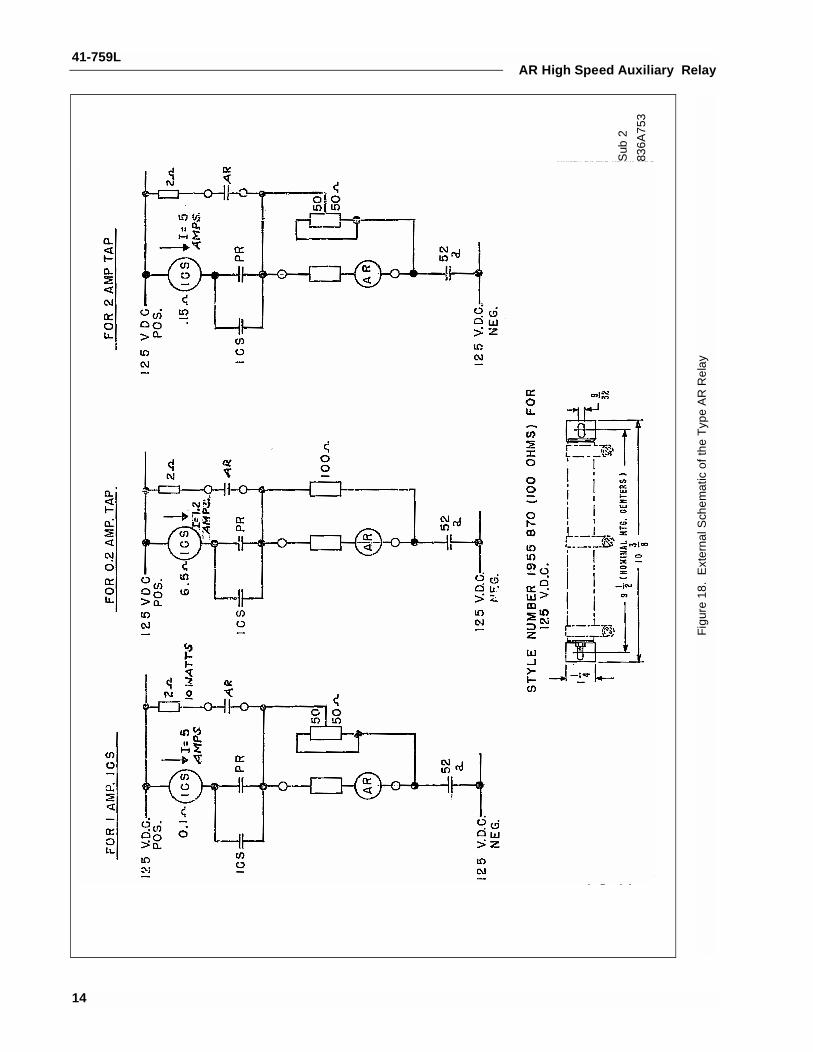
Fig
ure
18.
Ext
erna
l Sch
emat
ic o
f the
Typ
e A
R R
elay

41-759LAR High Speed Auxiliary Relay
Sub 2836A991
Figure 19 .Outline and Drilling Plan for the Type AR Relay in the Front Connected Molded Case.
15
41-759LAR High Speed Auxiliary Relay
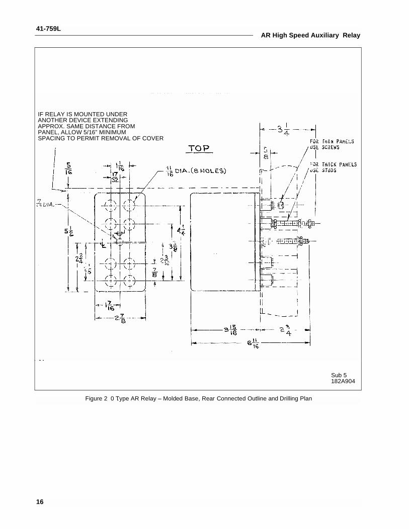
IF RELAY IS MOUNTED UNDERANOTHER DEVICE EXTENDINGAPPROX. SAME DISTANCE FROMPANEL, ALLOW 5/16” MINIMUMSPACING TO PERMIT REMOVAL OF COVER
Sub 5182A904
Figure 2 0 .Type AR Relay – Molded Base, Rear Connected Outline and Drilling Plan
16

41-759LAR High Speed Auxiliary Relay
*Sub 2057D7900
Figure 21. Outline and Drilling Plan for the Type AR Relay in the Ft-11 Case.
17
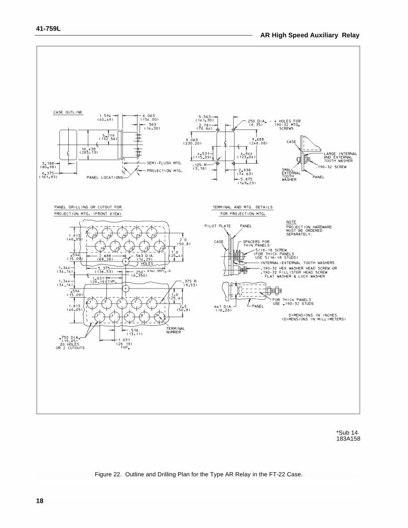
41-759LAR High Speed Auxiliary Relay
*Sub 14183A158
Figure 22. Outline and Drilling Plan for the Type AR Relay in the FT-22 Case.
18

41-759L
19
AR High Speed Auxiliary Relay
NOTES

ABB Inc.4300 Coral Ridge DriveCoral Springs, Florida 33065Telephone: +1 954-752-6700Fax: +1 954-345-5329www.abb.com/substation automation
IL 4
1-75
9 - R
evis
ion
L
ABB