rps lj manual april 2017 - relaypowersystems.com · rps instruction manual type lj - high speed...
TRANSCRIPT
INSTRUCTION MANUAL Relay Associates Type LJ - High Speed Auxiliary Relays
LJ12 LJ22 LJ32
Relay Associates brand is owned by Relay & Power Systems
APRIL 2017 | VERSION 1.3
Page 1 of 21
TABLE OF CONTENTS
GENERAL DESCRIPTION
LJ RELAY CONFIGURATION AND ORDERING INFORMATION
APPLICATION
SPECIFICATIONS AND RATINGS
CONTACT RATING FOR LJ RELAYS PER ANSI C37.90
RELAY COIL AND OPERATING SPECIFICATIONS
TARGET
ELECTRICAL SEAL-IN OPTION
RECEIVING
INSTALLATION
ADJUSTMENTS
TESTING PROCEDURES
ELECTRICAL OPERATION
MANUAL OPERATION
TEST SWITCHES
TYPICAL TERMINAL BLOCKS
STANDARD WIRING DIAGRAM
ELECTRIC SEAL IN WIRING SCHEMATIC
PANEL CUTOUT AND DRILLING FOR SEMI-FLUSH CASES
PROJECTION UNIT MOUNTING FOOTPRINTS
ABOUT US
Page 2 of 21
LIST OF TABLES
TABLE 1: MODEL IDENTIFICATION / ORDERING INFORMATION
TABLE 2: AVAILABLE LJ RELAY MODEL NUMBERS
TABLE 3: EXAMPLES 48V DC STANDARD MODELS
TABLE 4: EXAMPLES 125V DC STANDARD MODELS
TABLE 5: EXAMPLES 250V DC STANDARD MODELS
TABLE 6: CONTACT RATINGS
TABLE 7: RELAY SPECIFICATIONS
TABLE 8: CUTOUT DIMENSIONS (INCHES) FOR FLUSH CASES
LIST OF FIGURES
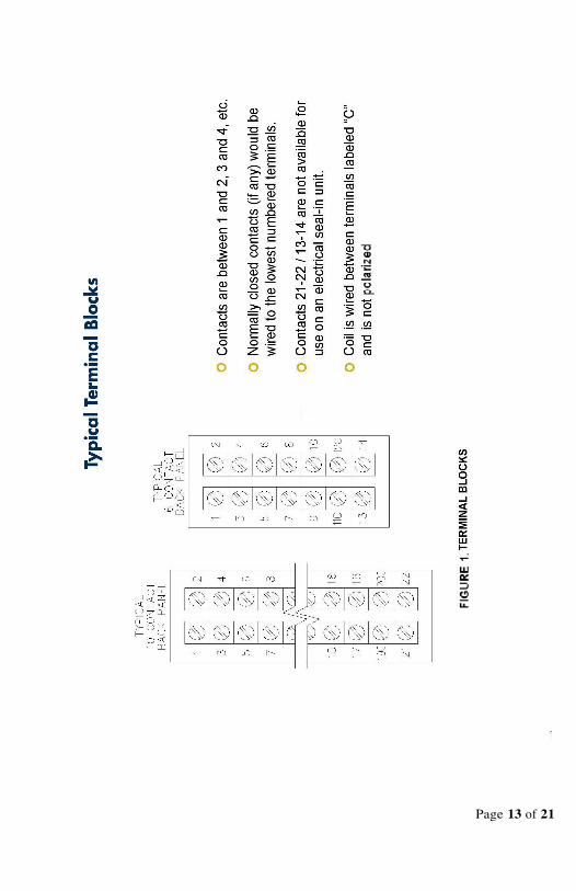
FIGURE 1: TERMINAL BLOCKS
FIGURE 2: STANDARD WIRING DIAGRAM (EXCLUDING LJ4X
SERIES)
FIGURE 3: ELECTRICAL SEAL IN WIRING SCHEMATIC
FIGURE 4: PANEL CUTOUT
FIGURE 5: PROJECTION MOUNT DRILLING DIMENSIONS
FIGURE 6: SCHEMATIC OF LJ41, LJ42, AND LJ43
Page 3 of 21
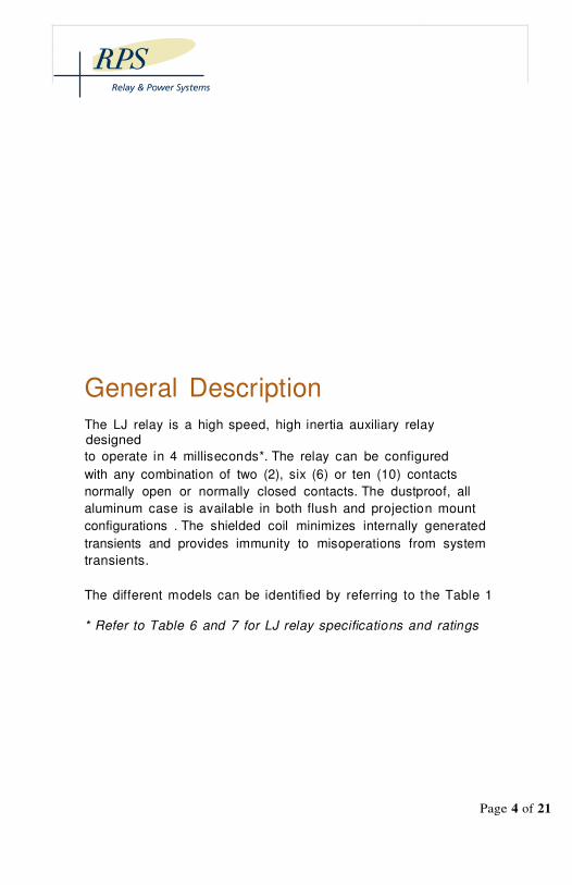
General Description
The LJ relay is a high speed, high inertia auxiliary relay designed
to operate in 4 milliseconds*. The relay can be configured
with any combination of two (2), six (6) or ten (10) contacts
normally open or normally closed contacts. The dustproof, all
aluminum case is available in both flush and projection mount
configurations . The shielded coil minimizes internally generated
transients and provides immunity to misoperations from system
transients.
The different models can be identified by referring to the Table 1
* Refer to Table 6 and 7 for LJ relay specifications and ratings
LJ Relay Configuration & Ordering Information
Page 4 of 21
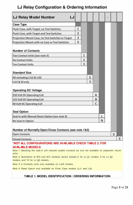
LJ Relay Configuration & Ordering Information
LJ Relay Model Number LJ
Case Type
Flush Case, with Target, no Test Switches 1
Flush Case, with Target and Test Switches 2
Projection Mount Case, no Test Switches or Target 3
Projection Mount with no Case or Test Switches 4
Number of Contacts
Two Contact Units (see note 3)
Six Contact Units
Ten Contact Units
Standard Size
All excluding LJ12 & LJ32
LJ12 & 32 only
Operating DC Voltage
250 Volt DC Operating Coil
125 Volt DC Operating Coil
48 Volt DC Operating Coil
Seal Option
Seal-In with Manual Reset Option (see note 4)
No Seal-In Option
Number of Normally Open/Close Contacts (see note 1&2)
Open Contacts
Closed Contacts
*NOT ALL CONFIGURATIONS ARE AVAILABLE CHECK TABLE 2. FOR
AVAILABLE MODELS Note 1. Selecting the seal-in unit reduces usable contacts by one not available on projec tion mount
uni ts
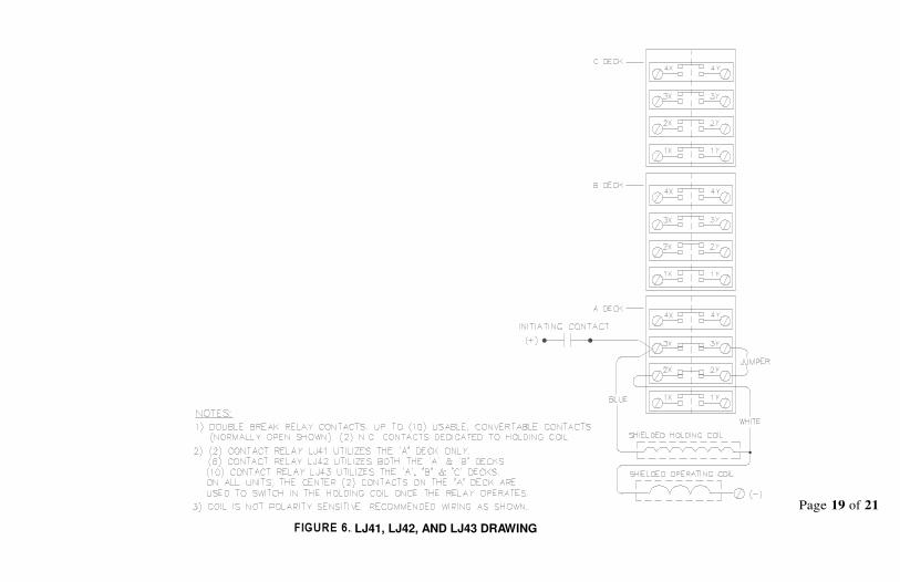
Note 2. Summation of N/O and N/C contacts cannot exceed 2 for LJ X1 models, 6 for LJ X2
model s, and 10 for LJ X3 model s.
Note 3. 2 Contacts units only available on LJ4X models.
Note 4. Reset Option only available on Flush Case models (LJ1 and LJ2)
TABLE 1. MODEL IDENTIFICATION / ORDERING INFORMATION
Page 5 of 21
-
E
S
A
B
C
L
N
X
X
1
2
3

LJ X X X X X - [XX]
1 2 S A N - [42], [60], [33]
1 2 S B N - [33], [42], [51], [60]
1 2 S C N - [33], [51]
1 3 E A N - [100], [82]
1 3 E B L - [100], [64]
1 3 E B N - [100], [46] ,[55], [64], [73], [82], [91]
1 3 E C N - [100], [55], [64]
2 2 E A N - [42], [51], [60]
2 2 E B N - [33], [42], [51], [60]
2 3 E A N - [100], [64], [73], [82]
2 3 E B L - [100], [46], [64]
2 3 E B N - [010], [100], [55], [64], [73], [82], [91]
2 3 E C N - [55], [73]
3 2 S B N - [33], [51], [42], [60]
3 2 S C N - [60], [33], [42]
3 3 E B N - [100], [55], [64], [73], [82], [91]
4 2 E B N - [33], [42], [24], [06], [60]
4 3 E B N - [100], [73], [55], [64]
4 3 E C N - [100], [73], [82]
TABLE 2. AVAILABLE LJ RELAY MODEL NUMBERS
LJ 1 3 E C N - 5 5
1 - Flush Case, with Target, N o Test Switches
3 - Ten Contacts
E - Standard Size
C - 48 Volt DC Operating Coil
N - No Seal-In Option
5 - Five Normally Open Conta cts
5 - Five Normally Closed Contacts
LJ 3 2 S C N - 3 3
3 - Projection Mount Case, No Test Switches or Target
2 - Six Contacts
S - Standard Size (LJ12 & LJ32 only)
C - 48 Volt DC Operating Coil
N - No Seal-In
3 - Three Normally Open Contacts
3 - Three Normally Closed Contacts
TABLE 3. EXAMPLES 48V DC STANDARD MODELS
Page 6 of 21

LJ 4 3 E B N - 6 4
4 - Projection Mount with No Case o r Test Switches
3 - Ten Co nta cts
E - Standard Size
B - 125 Volt DC Operating Coil
N - No Seal-In
6 - Six Normally Open Contacts
4 - Fo ur Normally Closed Contacts
LJ 2 3 E B L - 10 0
2 - Fl ush Case, with Target a nd Test Switches
3 - Ten Co nta cts
E - Standard Size
B - 125 Volt DC Operating Coil
L - Seal-In with Ma nual Reset
10 - Ten Norma lly Open Co ntacts
0 - Zero Normally Closed Co ntacts
TABLE 4. EXAMPLES 125V DC STANDARD MODELS
LJ 1 2 S A N - 4 2
1 - Flush Case, with Target, no Test Switches
2 - Six Co ntacts
S - Standard Size (LJ12 & LJ32 only)
A - 250 Volt DC Operating Coil
N - No Seal-In
4 - Four Normally Open Conta cts
2 - Two Normally Closed Co ntacts
LJ 2 3 E A N - 8 2
2 - Flush Case, with Target a nd Test Switches
3 - Ten Co ntacts
E - Standa rd Size
A - 250 Volt DC Operating Coil
N - No Seal-In
8 - Eight Normall y Open Co ntacts
2 - Two Normally Closed Contacts
TABLE 5. EXAMPLES 250V DC STANDARD MODELS
Page 7 of 21
Application
LJ auxiliary relays are mainly applied in protective relay
high speed tripping schemes in electric utility and industrial
substations .
general purpose applications.
Specifications
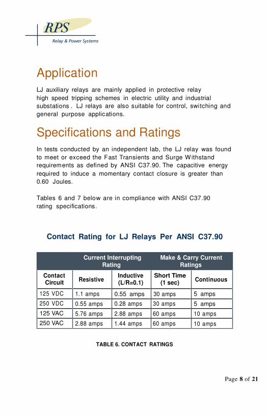
In tests conducted by an independent lab, the LJ relay was found
to meet or exceed the Fast Transients and Surge Withstand
requirements as defined by ANSI C37.90. The capacitive energy
required to induce a momentary contact closure is greater than
0.60 Joules.
Tables 6 and 7 below are in compliance with ANSI C37.90
rating specifications.
Rating for LJ Relays Per ANSI C37.90
Current Interrupting Make & Carry Current
Rating Ratings
Inductive Short Time (L/R=0.1) (1 sec)
0.55 amps 30 amps
0.28 amps 30 amps
2.88 amps 60 amps
1.44 amps 60 amps
TABLE 6. CONTACT RATINGS
LJ relays are also suitable for control, switching and
and Ratings
Contact
Contact Circuit
125 VDC
250 VDC
125 VAC
250 VAC
Continuous
5 amps
5 amps
10 amps
10 amps
Page 8 of 21
Resistive
1.1 amps
0.55 amps
5.76 amps
2.88 amps
Type LJ - High Speed Auxiliary Relays
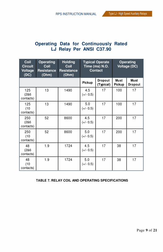
Operating Data for Continuously Rated LJ Relay Per ANSI C37.90
Coil Operating Holding
Circuit Coil Coil
Voltage Resistance Resistance
(DC) (Ohm) (Ohm)
125 13 1490 (2&6
contacts)
125 13 1490 (10
contacts)
250 52 8600 (2&6
contacts)
250 52 8600 (10 (+/- 0.5)
contacts)
1.9 1724 4.5 (+/- 0.5)
1.9 1724 5.0 (10 (+/- 0.5)
contacts)
TABLE 7. RELAY COIL AND OPERATING SPECIFICATIONS
Page 9 of 21
RPS INSTRUCTION MANUAL
Typical Operate Operating Time (ms) N.O. Voltage (DC)
Contact
Dropout Must Must
(Typical) Pickup Dropout
17 100 17
17 100 17
17 200 17
17 200 17
17 38 17
17 38 17
Pickup
4.5 (+/- 0.5)
5.0 (+/- 0.5)
4.5 (+/- 0.5)
5.0
48 (2&6
contacts)
48
Target
Operation
A direct driven, manually resettable target is standard on flush
mount units. When the relay operates, a bright orange target and
a small black reset tab are exposed.
Reset
After de-energizing the relay, pushing up the black tab will reset
the target. Target reset can only be accomplished manually.
Electrical Seal-In Option An LJ relay with this option will pick up and seal-in continuously
using a rated voltage source until reset by one of the methods
below. The recommended wiring for this option is shown in Figure
3. Due to internal space requirements, an LJ12 which is ordered
with this option will be supplied in a LJ13 case. (note: reduces
number of usable contacts by one)
Local Reset
When reset is desired, depress the small push-button located on
the front panel of the relay. This will interrupt the seal-in circuit
allowing the relay to reset.
Remote Reset
Remote reset of the coil can also be accomplished by connecting
a SCADA controlled normally closed contact, in series with the
electrical seal-in circuit (see Figure 3).
Page 10 of 21
RPS INSTRUCTION MANUAL Type LJ - High Speed Auxiliary Relays
Receiving
Upon receipt of the relay, inspect the relay to verify that its model
number agrees with the requisition. Also check for damage which
may have been sustained in transit. If damage is evident, file a
claim with the transportation company and notify your supplier or
Relay & Power Systems directly at 610-941-2900. If the unit is to
be stored, Relay & Power Systems recommend keeping the relay
in its original packaging to protect the unit. W hen handling the
relay, exercise reasonable care as to avoid severe impacts.
Installation
The relay is shipped from the factory pre-configured to
the customer’s specifications and should not require any
modifications on site. Mount the relays vertically on switchboard
instrument and control panels for proper target operation. Refer
to Figures 4 & 5 for LJ panel cutout and drilling dimensions,
respectively. Panel fasteners are included in the shipping
carton. Recommended terminal block and wiring connections for
different LJ models are shown in figures 1, 2, 3 and 6).
Adjustments LJ relays have been designed with no maintenance or
adjustments required to maintain reliable operability within
specified ratings.
Page 11 of 21
Testing Procedures
Electrical Operation
The relay can be tested by applying a rated DC voltage source
to the coil circuit. W hen the voltage source is applied, a
low resistance “operate” coil is energized to enable the high
speed operation. W hen the relay picks up, a high resistance
“holding” coil is switched into the circuit and allows the LJ to
be continuously energized with minimal current until the power
source has been removed.
Manual Operation
For testing purposes, the relay can also be operated manually by
inserting a small probe (e.g. #2 Phillip head screwdriver) through
the center hole of the nameplate. Pushing in on this probe will move
the armature, and thereby operate the contacts and target assembly
(note: Not applicable on LJ32 or LJ33).
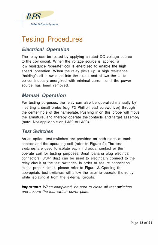
Test Switches
As an option, test switches are provided on both sides of each
contact and the operating coil (refer to Figure 2). The test
switches are used to isolate each individual contact or the
operate coil for testing purposes. Small banana plug electrical
connectors (3/64” dia.) can be used to electrically connect to the
relay circuit at the test switches. In order to assure connection
to the proper circuit, please refer to Figure 2. Opening the
appropriate test switches will allow the user to operate the relay
while isolating it from the external circuits.
Important: When completed, be sure to close all test switches
and secure the test switch cover plate.
Page 12 of 21
Page 13 of 21
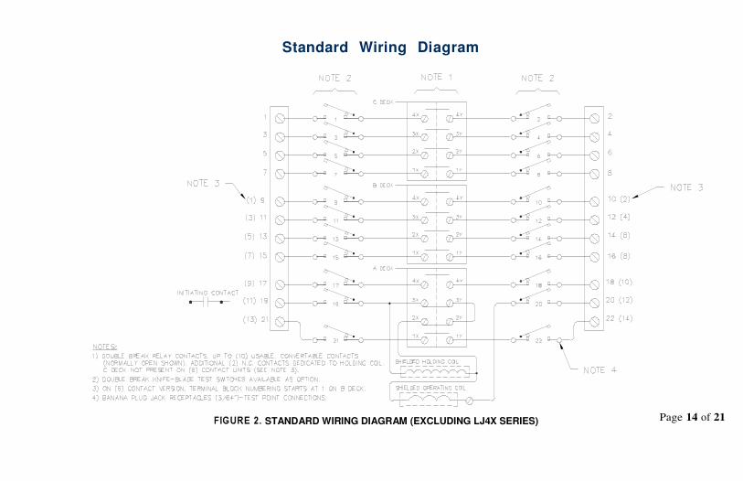
Standard Wiring Diagram
FIGURE 5. STANDARD WIRING DIAGRAM (EXCLUDING LJ4X SERIES) Page 14 of 21

Electric Seal in Wiring Schematic
FIGURE 6. ELECTRICAL SEAL IN WIRING DIAGRAM
Page 15 of 21
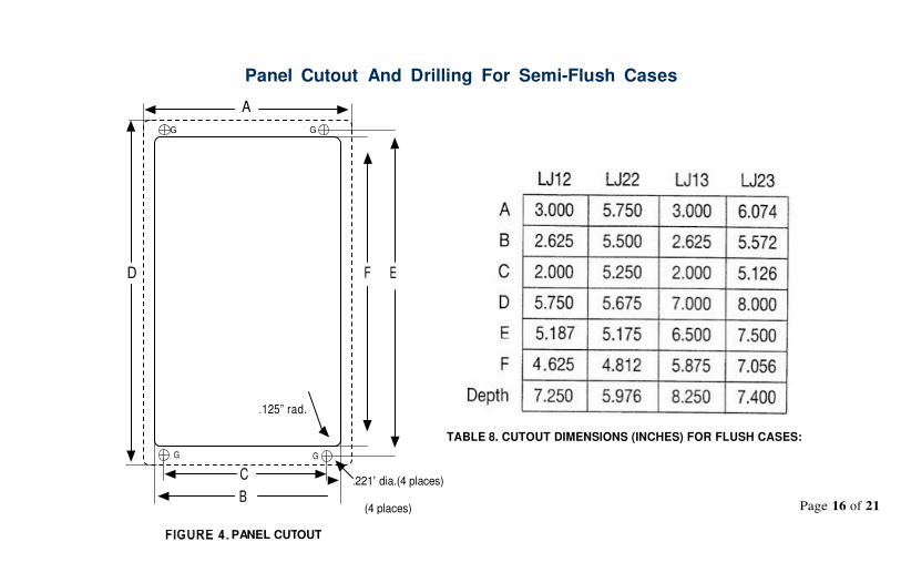
Panel Cutout And Drilling For Semi-Flush Cases
G
F E
.125” rad.
TABLE 8. CUTOUT DIMENSIONS (INCHES) FOR FLUSH CASES:
G
Page 16 of 21
A
G
D
G
C
B
FIGURE 7. PANEL CUTOUT
.221” dia.(4 places)
(4 places)

Projection Unit Mounting Footprints
FIGURE 8. PROJECTION MOUNT DRILLING DIMENSIONS
Page 17 of 21
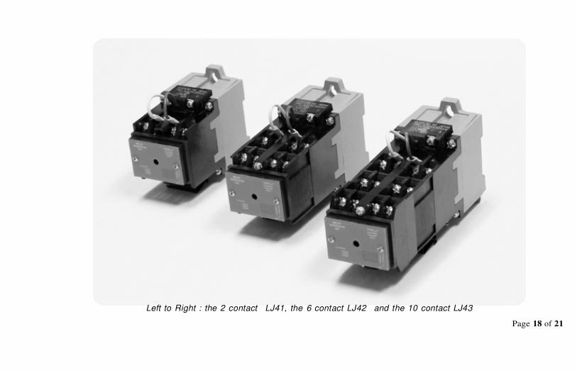
Left to Right : the 2 contact LJ41, the 6 contact LJ42 and the 10 contact LJ43
Page 18 of 21
Page 19 of 21
FIGURE 9. LJ41, LJ42, AND LJ43 DRAWING

Notes:
Page 20 of 21

RPS INSTRUCTION MANUAL
About Us
Relay & Power Systems
(RPS) is a full-service engineering and registered ISO
manufacturing resource, serving clients who produce, deliver and
consume medium & high voltage electrical power throughout the
Northeast and Mid-Atlantic US.
We offer a full range of services for delivering relay systems,
integrated power systems and control houses including:
engineering, system design, fabrication, testing, and
commissioning.
Relay & Power Systems – formally Relay Associates Inc - is a
wholly-owned subsidiary of Rumsey Electric. Since its founding
in 1895, Rumsey Electric has been a leading provider of
products and services to users and consumers of power in the
Northeastern United States.
17 Colwell Lane
Conshohocken, PA 19428
(P) 610.941.2900 (F) 610.941.3910
APRIL 2017 | VERSION 1.3 WWW.RELAYPOWERSYSTEMS.COM
Page 21 of 21
Type LJ - High Speed Auxiliary Relays