type 3766 pneumatic positioner type 3767 electropneumatic
TRANSCRIPT

Application
Single-acting or double-acting positioners for attachment topneumatic control valves. Supplied with a pneumatic inputsignal 0.2 to 1 bar or 3 to 15 psi (Type 3766) or an electricinput signal from 0/4 to 20 mA or 1 to 5 mA (Type 3767).
Rated travels from 7.5 to 120 mm or opening angle up to 90°
The positioners ensure a fixed assignment between the valve stemposition (controlled variable x) and the pneumatic or electric in-put signal (reference variable w). They compare the input signalreceived from the control unit with the travel of the control valveand, issue the corresponding output signal pressure pst (outputvariable y). A reversing amplifier for double-acting actuatorsproduces two opposed signal pressures.
Special features
• Arbitrary mounting position; suitable for normal orsplit-range operation; excellent dynamic response; negligiblysmall influence of supply air; adjustable proportional band(P-band); adjustable air output capacity; low air supply con-sumption; very insensitive to mechanical vibrations; low-maintenance compact design
• Versions for hazardous areas in type of protection "IntrinsicSafety" II 2G Ex ia IIC T6 or II 3G Ex nA II T6 for Zone 2(see "Summary of approvals")
• Type of protection "Flameproof Enclosure" Ex d withType 3766 Positioner and Type 6116 i/p Converter (Fig. 2)
• Special version with CrNiMo steel housing available
• Direct attachment to Type 3277 Pneumatic Actuator (Fig. 4)
• Attachment to actuators according to IEC 60534-6 (Fig. 3)
• Attachment to rotary actuators acc. to VDI/VDE 3845 (Fig. 5)
Benefits of integral positioner attachment (Fig. 4)
• Tight and exact mechanical connection between actuator andpositioner. No misalignment during shipping
• Concealed linkage protected against touch and external in-fluences to fulfill requirements of accident prevention regula-tions UVV (VBG 5)
• Simple pneumatic connection between actuator and positioner
• Presetting of the unit: Actuator with positioner
Optional pressure gauge for monitoring the input and outputsignal pressure (dial range from 0 to 6 bar and 0 to 90 psi).
Refer to Information Sheet T 8350 EN for details on the selectionand application of positioners, converters, limit switches and so-lenoid valves.
Versions
– Type 3766 · Pneumatic positioner
– Type 3767 · Electropneumatic positioner
Refer to article code for details on possible configurations.
Associated Information Sheet T 8350 EN Edition January 2010
Data Sheet T 8355 EN
Type 3766 Pneumatic Positioner
Type 3767 Electropneumatic Positioner
Fig. 1 · Type 3767 Electropneumatic Positioner
Fig. 3 · Attachment acc. toIEC 60534(NAMUR)
JIS
Fig. 2 · Type 3766 Ex d Positioner withType 6116 i/p Converter
Fig. 4 · Direct attachment toType 3241-7 ControlValve
Fig. 5 · Attachment toType 3278 Rotary Actuator
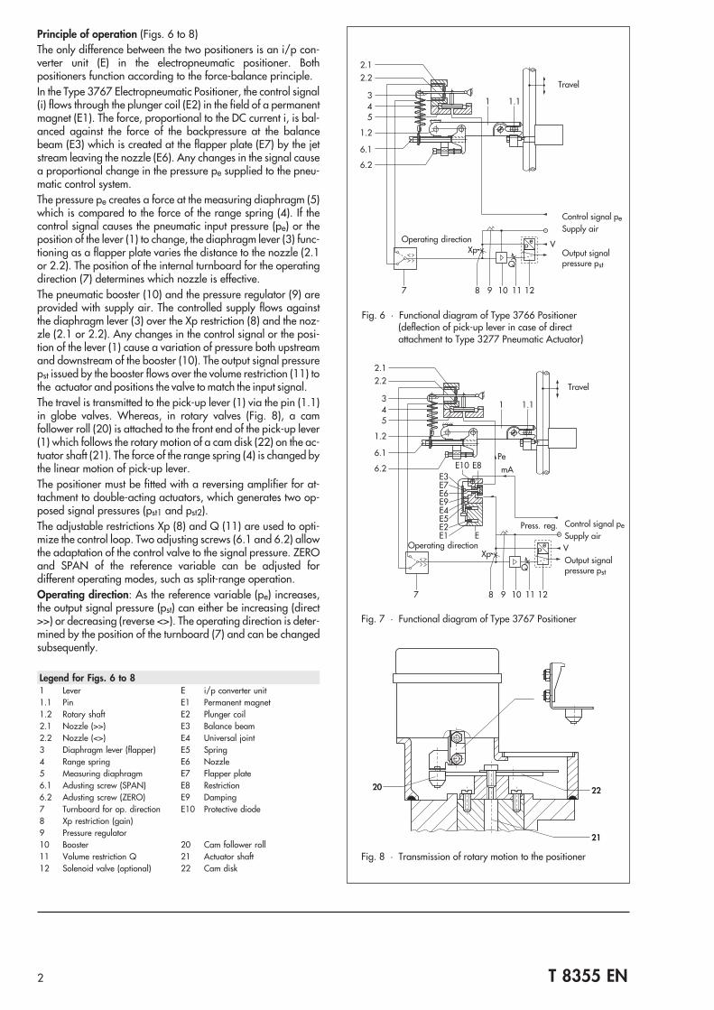
Principle of operation (Figs. 6 to 8)The only difference between the two positioners is an i/p con-verter unit (E) in the electropneumatic positioner. Bothpositioners function according to the force-balance principle.
In the Type 3767 Electropneumatic Positioner, the control signal(i) flows through the plunger coil (E2) in the field of a permanentmagnet (E1). The force, proportional to the DC current i, is bal-anced against the force of the backpressure at the balancebeam (E3) which is created at the flapper plate (E7) by the jetstream leaving the nozzle (E6). Any changes in the signal causea proportional change in the pressure pe supplied to the pneu-matic control system.
The pressure pe creates a force at the measuring diaphragm (5)which is compared to the force of the range spring (4). If thecontrol signal causes the pneumatic input pressure (pe) or theposition of the lever (1) to change, the diaphragm lever (3) func-tioning as a flapper plate varies the distance to the nozzle (2.1or 2.2). The position of the internal turnboard for the operatingdirection (7) determines which nozzle is effective.
The pneumatic booster (10) and the pressure regulator (9) areprovided with supply air. The controlled supply flows againstthe diaphragm lever (3) over the Xp restriction (8) and the noz-zle (2.1 or 2.2). Any changes in the control signal or the posi-tion of the lever (1) cause a variation of pressure both upstreamand downstream of the booster (10). The output signal pressurepst issued by the booster flows over the volume restriction (11) tothe actuator and positions the valve to match the input signal.
The travel is transmitted to the pick-up lever (1) via the pin (1.1)in globe valves. Whereas, in rotary valves (Fig. 8), a camfollower roll (20) is attached to the front end of the pick-up lever(1) which follows the rotary motion of a cam disk (22) on the ac-tuator shaft (21). The force of the range spring (4) is changed bythe linear motion of pick-up lever.
The positioner must be fitted with a reversing amplifier for at-tachment to double-acting actuators, which generates two op-posed signal pressures (pst1 and pst2).
The adjustable restrictions Xp (8) and Q (11) are used to opti-mize the control loop. Two adjusting screws (6.1 and 6.2) allowthe adaptation of the control valve to the signal pressure. ZEROand SPAN of the reference variable can be adjusted fordifferent operating modes, such as split-range operation.
Operating direction: As the reference variable (pe) increases,the output signal pressure (pst) can either be increasing (direct>>) or decreasing (reverse <>). The operating direction is deter-mined by the position of the turnboard (7) and can be changedsubsequently.
2.1
4
2.2
3
5
1.2
6.1
6.2
1
Pe
mAE10E3E7E6E9E4E5E2E1 E
E8
1.1
V
Q
Xp
7 8 9 10 11 12
ep
Fig. 7 · Functional diagram of Type 3767 Positioner
2 T 8355 EN
2.1
4
2.2
3
5
1.2
6.1
6.2
1 1.1
V
Q
Xp
7 8 9 10 11 12
ep
Fig. 6 · Functional diagram of Type 3766 Positioner(deflection of pick-up lever in case of directattachment to Type 3277 Pneumatic Actuator)
Travel
Operating direction
Control signal pe
Supply air
Output signalpressure pst
Fig. 8 · Transmission of rotary motion to the positioner
Legend for Figs. 6 to 81 Lever E i/p converter unit1.1 Pin E1 Permanent magnet1.2 Rotary shaft E2 Plunger coil2.1 Nozzle (>>) E3 Balance beam2.2 Nozzle (<>) E4 Universal joint3 Diaphragm lever (flapper) E5 Spring4 Range spring E6 Nozzle5 Measuring diaphragm E7 Flapper plate6.1 Adusting screw (SPAN) E8 Restriction6.2 Adusting screw (ZERO) E9 Damping7 Turnboard for op. direction E10 Protective diode8 Xp restriction (gain)9 Pressure regulator10 Booster 20 Cam follower roll11 Volume restriction Q 21 Actuator shaft12 Solenoid valve (optional) 22 Cam disk
Travel
Press. reg. Control signal pe
Supply air
Output signalpressure pst
Operating direction

3 T 8355 EN
Table 1 · Technical data · All pressures in bar (gauge)
Type 3766 and Type 3767 Positioners
Travel rangeDirect attachment to Type 3277 Actuator: 7.5 ... 30 mmAttachment acc. to IEC 60534 (NAMUR): 7.5 ... 120 mm
Opening angle 70°, 75° or 90° depending on cam diskReference variablewType 3766
Signal range bar (psi) 0.2 ... 1 bar (3 ... 15 psi)Span bar (psi) 0.4 ... 0.8 bar (6 ... 12 psi)Overloadabe max. 2 bar (29 psi)
Reference variablewType 3767
Signal range Two-wire device, reverse polarity protection0/4 ... 20 mA 1 ... 5 mA
Span 8 ... 20 mA 2 ... 4 mAInternal resistance Ri at 20 °C 200 Ω 880 Ω
Supply air Supply air range 1.4 ... 6 bar (20 ... 90 psi)Air quality acc. toISO 8573-1 (2001-02)
Maximum particle size and density: Class 4 · Oil contents: Class 3; Pressure dew point:Class 3 or at least 10 K below the lowest ambient temperature to be expected
Output signal pressure pst Can be limited between 0 ... approx. 2.5 and 0 ... 6 bar (0 ... approx. 35 and 0 ... 90 psi)
CharacteristicLinear
Deviation from terminal-based conformity: ≤ 1 %Hysteresis ≤ 0.3 %Sensitivity ≤ 0.1 %Operating direction ReversibleProportional band Xp 0.5 ... 2.5 % (proportional-action coefficient Kp: > 200 ... 40)Air consumption With air supply of 1.4 bar With air supply of 6 bar
Type 3766 ≤ 230 In/h ≤ 230 In/h 1)
Type 3767 ≤ 280 In/h ≤ 280 In/h 1)
Air delivery Actuator filled with air 3.0 mn3/h 8.5 mn3/hActuator vented 4.5 mn3/h 14.0 mn3/h
Permissibleambienttemperature 7)
Type 3766 Standard –20...80 °C: Optional limit switches/solenoid valve/position transmitterwith plastic cable gland
–40...80 °C: Optional limit switches/solenoid valve with metal cable glandLow temperature version –50...80 °C: Optional limit switches/solenoid valve with metal cable glandType 3767 Standard –20...80 °C: Optional limit switches/solenoid valve/position transmitter
with plastic cable gland–40...80 °C: Optional limit switches/solenoid valve with metal cable gland
Low temperature version –45...80 °C: Optional limit switches/solenoid valve with metal cable glandInfluence Temperature: ≤ 0.3 %/10 K · Supply air: ≤ 1 % between 1.4 ... 6 barElectromagnetic compatability Requirements specified in EN 61000-6-2 and EN 61000-6-3 are metVibrations No influence between 10 und 150 Hz and 4 gExplosion protection 2) Type of protection II 2G Ex ia IIC T6 or II 3G Ex nA II T6 for Zone 2Degree of protection IP 54 (IP 65 and NEMA 4 possible by fitting a filter check valve (see accessories))Weight Approx. 1 kgAdditional equipmentLimit switches2 inductive proximity switches Type SJ 2-SNControl circuit Specifications corresponding to the connected switching amplifierHysteresis at rated travel ≤ 1 %
Solenoid valveInput Binary DC voltage signalNominal signal 6 V DC 12 V DC 24 V DCSignal “0” (off) 3) ≤ 1.2 V ≤ 2.4 V ≤ 4.7 VSignal “1” (on) 4) ≥ 5.4 V ≥ 9.6 V ≥ 18.0 VMaximum permissible signal 28 V 25 V 32 VInternal resistance Ri at 20 °C 2909 Ω 5832 Ω 11714 Ω
Air consumption in steady state In addition to the positioner “Off” ≤ 60 ln/h · “On” ≤ 10 ln/h 1)
Closing time forrated travel andsignal pressurerange (KVS 0.14)
Type 3277 Actuator 120 cm² 240 cm² 350 cm² 700 cm²0.2 ... 1 bar ≤ 0.5 s ≤ 0.8 s ≤ 1.1 s ≤ 4 s0.4 ... 2 bar ≤ 0.5 s ≤ 2 s ≤ 2.5 s ≤ 8 s0.6 ... 3 bar 6) ≤ 1 s ≤ 1.5 s ≤ 5 s
Analog position transmitter 8)
Output Two-wire device 4 ... 20 mAAuxiliary power
Minimum terminal voltage: 12 Vmaximum: 45 V
The position transmitter may only beconnected to a certified intrinsically safe
circuit 5)
1) With pressure regulator at minimum setting 2) Refer to Table 2 for explosion-protected version3) DC voltage signal at –25 °C 4) DC voltage signal at +80 °C5) e.g. over SAMSOMATIC 994-0103-KFD2-STC4-Ex1 Loop Isolator 6) Actuator 120 cm² for all signal pressure ranges: ≤ 0.5 s7) The limits specified in the EC Type Examination Certificate additionally apply to explosion-protected devices.8) Available until March 2011

Additional equipment
The positioners can optionally be equipped with the followingadditional equipment.
Positioner with inductive proximity switches (Fig. 9)This positioner version has a rotary shaft (1.2) with two adjust-able metal tags (33) for inductively actuating the proximityswitches (34). The switches are continuously adjustable and canbe overridden.To operate them, corresponding switching amplifier must beconnected in the output circuit.
The proximity switches can also be retrofitted.
Positioner with solenoid valve (Fig. 10)The positioners can be fitted with an intrinsically safe, pi-lot-operated solenoid valve also in combination with the induc-tive limit switches. When the positioner is equipped with this so-lenoid valve, the control valve can be moved to the fail-safe po-sition regardless of the positioner's output signal.
The solenoid valve essentially consists of an electropneumaticconverter (12.1) and a 3/2-way solenoid valve (12.2). If a con-trol signal corresponding to the binary signal 0 (off) is appliedto the input, the nozzle (12.3) of the electropneumatic converteris opened, the signal pressure pst is blocked and air is vented outof the actuator. The force of the compression springs in the actu-ator move the control valve to its fail-safe position.
If a control signal corresponding to binary signal 1 (on) is ap-plied to the input, the relay coil (12.4) is energized, and theflapper plate (12.5) closes the nozzle (12.3). The increasingcascade pressure switches over the 3/2-way valve (12.2). Inthis switching position, the output signal pressure pst is appliedto the actuator. The control valve is in control operation.
The solenoid valve can also be retrofitted.
Legend to Figs. 9 and 10
1.2 Rotary shaft 12.5 Flapper plate
12 Solenoid valve 12.6 Restriction
12.1 i/p converter
12.2 3/2-way valve 32 Adjusting screw
12.3 Nozzle 33 Metal tag
12.4 Relay coil 34 Proximity switch
4 T 8355 EN
Table 2 · Technical data for Type of Protection Ex ia IIC
i/p converter (Type 3767 only)
Maximum values for For connection to certified intrinsicallysafe circuits
U0 28 V 25 V
I0 85 mA 100 mA 120 mA
P 0.7 W 0.7 W 0.7 W
Temperature class T6(–45 to 60 °C)
T5(–45 to 70 °C)
T4(–45 to 80 °C)
Internal inductance and capacitance are negligibly small
Inductive proximity switches
Maximum values for For connection to certified intrinsicallysafe circuits
U0 16 V
I0 52 mA/25 mA
P 169 mW/64 mW
Internal inductance Li = 100 µH
Internal capacitance Ci = 30 nF
Solenoid valve
Nominal signal 6 V 12 V 24 V
Maximum values for For connection to certified intrinsicallysafe circuits
U0 (V) 25 27 28 30 32
I0 (mA) 150 125 115 100 90
Internal inductance and capacitance are negligibly small
Analog position transmitter
Maximum values for For connection to certified intrinsicallysafe circuits
U0 28 V
I0 115 mA
P 1 W
Ci 5.3 nF
Internal inductance negligibly small
Permissible ambient temperatures
Specifications as stated in the EC Type Examination CertificatePTB 01 ATEX 2167 and the Statement of Conformity PTB 01 ATEX2170 X.
Fig. 9 · Inductive proximity switches
12.5
12.3
12.1
12.4+
– u[V]
12.6
12.2
Fig. 10 · Functional diagram of the solenoid valve
32 1.2 33 34
34
32
1.2
Switch B Switch AMetal tag for switch B
Metal tag forswitch A
Input
Auxiliary power
Venting intopositioner housing
Signal pressure toactuator
Signal pressure frompositioner

Positioner with analog position transmitter
Due to the amount of space that the position transmitter re-quires, please note that this option cannot be combined withlimit switches or a solenoid valve!
The position transmitter allows the position of the closure mem-ber of the valve (i.e., valve travel or opening angle) to be con-verted into a proportional output signal from 4 to 20 mA. Limitpositions such as “Valve open” or “Valve closed” are indicatedas well as all intermediate positions.
Attachment (Figs. 12 and 13)The positioner can be attached to linear actuators either directly(Type 3277 Pneumatic Actuator) or according to IEC 60534(NAMUR) (Type 3271 Pneumatic Actuator). Rotary actuatorswith an interface according to VDI/VDE 3845 require an inter-mediate piece to mount the positioner.
Arrangement of the positioner and the actuator (Fig. 11)How the positioner and actuator can be arranged depends onthe operating direction of the input signal (pe) and the outputsignal pressure (pst) as well as the fail-safe action of the actua-tor:
“Actuator stem extends”
“Actuator stem retracts”
Direct attachment to Type 3277 Pneumatic Actuator (Fig. 4)This method of attachment provides the benefit of being aself-contained, preset actuator and positioner unit. A connec-tion block is required for direct attachment to actuators with240, 350 and 700 cm² effective diaphragm areas (Fig. 11).
With an actuator with fail-safe action “Actuator stem extends”,the output signal pressure pst issued by the positioner is routedto the bottom diaphragm case over the connection block and ahole in the actuator yoke. In case the spring chamber needs befilled with the exhaust air from the positioner, the air can be con-nected to the connection block using a ready-made pipe.
With an actuator with fail-safe action “Actuator stem retracts”the output signal pressure pst issued by the positioner isconnected to the top diaphragm case over a ready-made pipe.The bottom diaphragm chamber (spring chamber) can be filledwith the exhaust air from the positioner without additional mea-sures over an internal hole.
The signal pressure connection is located at the back of thepositioner for Type 3277-5 Pneumatic Actuator (120 cm² dia-phragm area), therefore eliminating the need for external pip-ing.
5 T 8355 EN
Fig. 11.3 · Operating direction <> Left attachment Fig. 11.4 · Operating direction >> Right attachment
Fig. 11 · Direct attachment to Type 3277 Actuator
Fig. 11.1 · Operating direction >> Left attachment Fig. 11.2 · Operating direction<> Right attachment
Fail-safe action: Actuator stem retracts
Fail-safe action: Actuator stem extends
Table 3 · Direct attachment: Assignment of travel and rangespring
Actuator size in cm² Travel in mm Range spring
120/240/350 7.5 2
120/240/350 15 1
700 15 2
700 30 1
The positioner is delivered with range spring 1. Range spring 2is included in the accessories.
Signal pressurepiping pst
Connection block
Connection block
Internal signalpressure connection

Attachment according to IEC 60534 (Figs. 3 and 12)The positioners can be attached to actuators with cast yokes(Fig. 3) (e.g. Series 240, 250 and 280) and valves withrod-type yokes (Fig. 12) using an adapter (15). A clampingplate (15.1) is additionally required for valves with rod-typeyokes.
By selecting the appropriate lever (1) and link point on the lever(16), the positioners can be matched to different travels rangingfrom 7.5 to 120 mm.
There is no prescribed mounting position for the positioner. Theoperating direction is determined by how the positioner and theadapter are arranged and how the internal turnboard is posi-tioned.
Select the range spring according to Table 4.
Attachment to rotary actuators (Fig. 13)The positioners can be attached to the Type 3278 Rotary Actua-tor or any rotary actuators with an interface according toVDI/VDE 3845 over an intermediate piece (2). The rotary mo-tion of the actuator is converted into a linear motion required bythe positioner by the cam disk (7). A cam follower roll (3) is at-tached to the lever (5) of the positioner to trace the motion of thecam disk. Various cams disks are available depending on thecontrol valve characteristic required (e.g. linear or equal per-centage).
Double-acting, springless actuators require additionally apneumatic reversing amplifier which produces two opposedsignal pressures.
Select the range spring as follows:
Reference variable for split-range operation: Range spring 1
Reference variable for normal signal range: Range spring 2
The positioner is always delivered with range spring 1; rangespring 2 is included in the mounting kit for rotary actuators.
6 T 8355 EN
Table 4 · Assignment of travel and range springfor attachment according to IEC 60534
Travel mm Range spring
7.5 ≤ 15 2
> 15 ≤ 60 1
22 ≤ 120 1
The positioner is delivered with range spring 1. Range spring 2is included in the accessories.
Fig. 13 · Attachment to rotary actuators
Fig. 12 · Attachment to valves with rod-type yoke
9
1
2
5
3
4
11
10
8 67
1
16
15 15.1
Legend for Fig. 13
1 Positioner 8 Actuator shaft
2 Intermediate piece 9 Plate
3 Lever with cam follower roll 10 Mounting bracket
4 Adapter 11 Coupling
5 Feedback lever 15 Adapter
6 Scale 15.1 Plate
7 Cam disk 16 Slide
For SAMSON Type 3278
Acc. to VDI/VDE 3845

7 T 8355 EN
+ –
+ – A
+51 –52 +81 –82 +31 –32
(B) A
(A) B
+41 –42
GEi
+11 –12 +41 –42 +51 –52 +81 –82
AEi
+11 –12 +31 –32
AEi G
Ei
+ – Us
+ –
(B) A
(A) B
+ –
Input
Switching amplifieracc. to EN 60947-5-6
Output Aux. power
Fig. 14.1 · Type 3766Marking(A), (B) on rear
Us
Power supply unit
Control signal i [mA]Switching amplifier
acc. to EN 60947-5-6
Solenoid valve
Output Aux. power
Control signal i [mA] Power supply unit for optional
position transmitter
Fig. 14.2 · Type 3767
Materials
Housing
Special version
Die-cast aluminumchromated and plastic coatedCrNiMo steel, 1.4404 (316 L)
External parts Stainless steel 1.45711.4305
Measuring diaphragm Fluorosilicone rubber
Electrical connections
Dimensions in mm
36
N1 = 113N2 = 200
58
56
68185
29
16
4
76
15
0
50
Attachment acc. toIEC 60534and NAMUR
44
19.5
3935
68185
164
29
50
46 76
50
150
82
56 66
28.5
28.5
Output 1 (A1)
Output 2 (A2)
Supply (Z)Attachment to rotary actuators(with pneum. reversing amplifier)
Fulc
rum
28
14
29
15
0
16
41
9.5
37
68185
76
Supply(9)
Output(36)
M20x1.5
Direct attachment toType 3277 Actuator

8 T 8355 EN
Summary of explosion protection approvals for Type 3766 Positioner
Type of approval Certificate number Date Comments
EC Type Examination Certificate PTB 01 ATEX 2171 2001-11-26 II 2G Ex ia IIC T6, Type 3766-1
Statement of Conformity PTB 01 ATEX 2195 X 2002-03-07 II 3G Ex nA II T6, Zone 2,Type 3766-8
IECEx approval IECEx TSA 05.0004X 2005-05-24 Ex ia I/IIC T6 IP 65,Ex n l/IIC T6 IP 65,without solenoid valve module with inductive limit switches,Type 3766-6
GOST certificate POCC DE 08.B00045 2012-02-28 Ex approval; valid until 2015-02-27
CSA approval 1607848 2005-09-16 Ex ia IIC T6; Class I, Zone 0Class I, Div. 1, Groups A, B, C; Class IIISolenoid valve, position transmitter, inductive limit switchesType 3766-3
FM approval 3020228 2005-07-21 Class I, II, III Div. 1; Groups A, B, C, D, E, F, GCl. I, Zone 0 AEx ia IIC T6;Cl. I, Div. 2, Gr. A, B, C, DCl. II; Div. 2, Gr. F, G; Cl. III;NEMA 4X; with position feedback, solenoid valve, inductivelimit switchesType 3766-3
Refer to Data Sheet T 6116 EN for Ex d approvals for Type 6116 i/p Converter (Fig. 2)
Summary of explosion protection approvals for Type 3767 Positioner
Type of approval Certificate number Date Comments
EC Type Examination Certificate PTB 01 ATEX 2167 2001-11-29 II 2G Ex ia IIC T6; Type 3767-1
Statement of ConformityFirst Addendum
PTB 01 ATEX 2170 X 2002-03-072003-05-28
II 3G Ex nA II T6; Zone 2;Type 3767-8
IECEx approval IECEx TSA 05.0004X 2005-05-24 Ex ia I/IIC T6 IP 65, Ex nl/IIC T6 IP 65,without solenoid valve module with inductive limit switches,Type 3767-6
GOST certificate POCC DE 08.B00045 2012-02-28 Ex approval; valid until 2015-02-27
CSA approval 1607848 2005-09-16 Ex ia IIC T6; Class I, Zone 0Class I, Div. 1, Groups A, B, C; Class IIISolenoid valve, position transmitter, inductive limit switchesType 3767-3
FM approval 3020228 2005-07-21 Cl. I, II, III, Div. 1; Gr. A, B, C, D, E, F, GCl. I, Zone 0 AEx ia IIC T6;Cl. I, Div. 2; Gr. A, B, C, DCl. II, Div. 2; Gr. F, G; Cl. III; NEMA 4X;with position feedback, solenoid valve, inductive limitswitches;Type 3766-3
JIS approval TC-13674 2005-07-09 Ex ia IIC T6; Type 3767-7
KOSHA 13-KB4BO-0037 2013-01-31 Ex ia IIC T6/T5/T4; Type 3767-1

9 T 8355 EN
Article code
Pneumatic Positioner Type 3766- x x x 0 1 x x x x 1 x 0 x 0
Explosion protection
Without 0 2
II 2G Ex ia IIC T6 acc. to ATEX 1
FM/CSA intrinsically safe / non incendive 3
Ex ia / Ex n I/IIC T6 IP 65 IECEx TSA Australia 6
II 3G Ex nA II T6 acc. to ATEX 8
Additional equipment
Without 0
Limit switch, inductive, 2x SJ2 SN 2
Analog position transmitter 4 to 20 mA* 6 0 0
3/2-way solenoid valve
Without 0
6 V DC 2
12 V DC 3
24 V DC 4
Pneumatic connections
¼-18 NPT 1
ISO 228/1 - G ¼ 2
Electrical connections
Without (without additional equipment, without solenoid valve) 0 0 0 0
Cable gland
M20 x 1.5, blue (plastic) 1 0 0
M20 x 1.5, black (plastic) 2 0 0
M20 x 1.5 (nickel-plated brass) 2 1 3
Housing version
Die-cast aluminum 0
Stainless steel (CrNiMo) 2
Temperature range
Standard 0
Low temperature
Tmin ≥ –50 °C; optional limit switches, solenoid valve 2 1 3
Special version
None 0 0 0
GOST approval 1 0 1 0
* Available until March 2011
Device functioning only as analog position transmitter: 3766-x60 000xxx00 000 0

10 T 8355 EN
Article code
Electropneumatic Positioner Type 3767- x x x 0 1 x x x x x x 0 x 0
Explosion protection
Without 0 2
II 2G Ex ia IIC T6 acc. to ATEX 1
FM/CSA intrinsically safe/non incendive 3
II 3G Ex nA II T6 acc. to ATEX 8
Additional equipment
Without 0
Limit switch, inductive, 2x SJ2 SN 2
Analog position transmitter 4 to 20 mA* 6 0
3/2-way solenoid valve
Without 0
6 V DC 2
12 V DC 3
24 V DC 4
Type of mounting
Standard range spring 0 1
Pneumatic connections
¼-18 NPT 1
ISO 228/1 - G ¼ 2
Electrical connections
Cable gland
M20 x 1.5, blue (plastic) 1 0
M20 x 1.5, black (plastic) 2 0
M20 x 1.5 (nickel-plated brass) 2 1
Housing version
Die-cast aluminum 1
Stainless steel (CrNiMo) 2
Reference variable
4 to 20 mA 1
0 to 20 mA 2
1 to 5 mA 3
Temperature range
Standard 0
Low temperature
Tmin ≥ –45 °C; optional limit switches, solenoid valve 2 1 2
Special version
None 0 0 0
GOST approval 1 0 1 0
* Available until March 2011

Ordering text
Type 3766 Pneumatic Positioner
or
Type 3767 Electropneumatic Positioner
Accessories
– Adapter NPT for electrical connections
– Range spring 2
– Filter check valve in housing with G ¼ thread made of
– Polyamide, IP 65
– 1.4301, IP 65
– Polyamide, NEMA 4
– 1.4301, NEMA 4
Additional specifications
– Without/with pressure gauge for output signal pressure andsupply air
For mounting to the control valve:
– Reference variable preset
Operating direction: Increasing/increasing orincreasing/decreasing
– Positioner with inductive limit switches:
Metal tag outside the pick-up field – Contact closed/
Metal tag inside the pick-up field – Contact open
– Direct attachment to Type 3277 Actuator (120 to 700 cm²)
– Attachment acc. to IEC 60534-6 (NAMUR)
Travel: ... mm, if applicable, rod diameter: ... mm
– Attachment to Type 3278 Rotary Actuator (160 or 320 cm²)
– Attachment to rotary actuators acc. to VDI/VDE 3845,single-acting or double-acting
– Linear or equal percentage valve characteristic
– Opening angle 70°/75°/90°
Refer to the Mounting and Operating InstructionsEB 8355-1 EN (for Type 3766) or EB 8355-2 EN (forType 3767) concerning the mounting parts required when thepositioner is delivered unattached to a control valve.
Specifications subject to change without notice
11 T 8355 EN

T 8355 EN
SAMSON AG · MESS- UND REGELTECHNIKWeismüllerstraße 3 · 60314 Frankfurt am Main · GermanyPhone: +49 69 4009-0 · Fax: +49 69 4009-1507Internet: http://www.samson.de 2
01
4-0
1