type 3766 pneumatic positioner · type 3767 ... · pdf filethe only difference between...
TRANSCRIPT

Data Sheet T 8355 EN
Associated Information Sheet T 8350 Edition December 2016
Fig. 1: Type 3766/Type 3767 Positioner
Fig. 2: Type 3766 Ex d Positioner with Type 6116 i/p Converter
Fig. 3: Attachment according to IEC 60534 (NAMUR)
Fig. 4: Direct attachment to Type 3241-7 Control Valve
Fig. 5: Attachment to Type 3278 Rotary Actuator
The positioners ensure a predetermined assignment of the valve position (controlled variable x) to the input signal (refer-ence variable w). They compare the input signal received from a control system to the travel of the control valve and issue a corresponding output signal pressure pst (output variable y). A reversing amplifier for double-acting actuators produces two opposed signal pressures.
Special features • Any mounting position possible, suitable for normal or
split-range operation, excellent dynamic response, negligi-bly small influence of supply air, adjustable proportional band (P band), adjustable air output capacity, low air supply consumption, very insensitive to mechanical vibra-tions, low-maintenance compact design.
• Versions for use in hazardous areas in type of protection intrinsic safety II 2G Ex ia IIC T6 or II 3G Ex nA II T6 for Zone 2
• Type of protection "Flameproof enclosure" Ex d with Type 3766 Positioner and Type 6116 i/p Converter (Fig. 2)
• Direct attachment to Type 3277 Actuator (Fig. 4) • Attachment to actuators according to IEC 60534-6 (Fig. 3) • Attachment to rotary actuators according to VDI/
VDE 3845 (Fig. 5)
Benefitsofdirectpositionerattachment(Fig. 4) • Tight and exact mechanical connection between actuator
and positioner. No misalignment during shipping. • Travel pick-off protected against touching and external in-
fluences, meeting the requirements of the German Acci-dent Prevention Regulations (VBG 5)
• Simple pneumatic connection between actuator and posi-tioner
• Ready-adjusted unit: actuator with positionerOptionally with pressure gauge for monitoring the supply air and signal pressure (dial range from 0 to 6 bar and 0 to 90 psi).For more information on the selection and application of posi-tioners, converters, limit switches, and solenoid valves, refer to Information Sheet u T 8350.
Type 3766PneumaticPositionerType 3767ElectropneumaticPositioner
ApplicationSingle-acting or double-acting positioners for attachment to pneumatic control valves. These positioners use a pneumatic input signal from 0.2 to 1 bar or 3 to 15 psi (Type 3766) or an electric input signal from 0/4 to 20 mA or 1 to 5 mA (Type 3767).Ratedtravelsfrom7.5to120 mmoropeninganglesupto90°

2 T 8355 EN
Principleofoperation(Fig. 6)The positioners are used to assign the valve position (controlled variable x) to the input signal (reference variable w). The posi-tioners compare the control signal of a control system to the travel of the control valve and issues a signal pressure (output variable) for the pneumatic actuator.Both positioners function according to the force-balance princi-ple. The only difference between the two positioners is an i/p converter unit in the Type 3767 Electropneumatic Positioner.
Type 3766·PneumaticpositionerThe positioner consists of a lever for travel pick-up, a measur-ing diaphragm, and the pneumatic control system with noz-zle, diaphragm lever (flapper plate), and booster.The valve travel, i.e. the valve position, is transmitted to the pick-up lever (1) over the pin (1.1) and determines the force of the range spring (4). This force is compared to the position-ing force generated by the pressure pe at the measuring dia-phragm (5).If either the control signal or the valve position changes, the diaphragm lever (3) moves, altering the distance to the nozzle (2.1 or 2.2), depending on the adjusted direction of action of the positioner.The supply air is supplied to the booster (10) and the pressure regulator (9). The controlled supply air flows through the Xp restriction (8) and the nozzle (2.1, 2.2) and hits the dia-phragm lever (flapper plate).
Type 3767·ElectropneumaticpositionerThe positioner consists of an electropneumatic converter and a pneumatic unit equipped with a lever for travel pick-up, a measuring diaphragm, and the pneumatic control system with nozzle, diaphragm lever (flapper plate), and booster.The control signal, e.g. 4 to 20 mA, issued by the controller is transmitted to the electropneumatic converter (13) where it is converted into a proportional pressure signal pe.The valve travel, i.e. the valve position, is transmitted to the pick-up lever (1) over the pin (1.1) and determines the force of the range spring (4). This force is compared to the posi-tioning force generated by the pressure pe at the measuring diaphragm (5).If either the control signal or the valve position changes, the diaphragm lever (3) moves, altering the distance to the nozzle (2.1 or 2.2), depending on the adjusted direction of action of the positioner.The supply air is supplied to the booster (10) and the pressure regulator (9).The controlled supply air flows through the Xp restriction (8) and the nozzle (2.1, 2.2) and hits the diaphragm lever (flap-per plate).
Type 3766andType 3767Any change in the reference variable or the valve position causes the pressure to change upstream or downstream of the booster.The air controlled by the booster (signal pressure pst) flows through the volume restriction (11) to the pneumatic actuator, causing the plug stem to move to a position corresponding to the reference variable.The adjustable Xp restriction (8) and volume restriction (11) are used to optimize the positioner control loop.The pick-up lever (1) and the range spring (4) must be select-ed to match the rated valve travel and the nominal span of the reference variable.The positioner can be additionally equipped with either induc-tive limit contacts and/or a solenoid valve or position trans-mitter.
Additional equipment
PositionerwithinductivelimitcontactsIn this version, the rotary shaft of the positioner carries two adjustable tags which actuate the built-in proximity switches.
PositionerwithsolenoidvalveWhen the positioner is equipped with a solenoid valve, the valve can be moved to the fail-safe position, regardless of the positioner's output signal. If a control signal corresponding to the binary signal '0' (OFF) is applied to the input, the signal pressure pst is shut off and the actuator is vented. The actuator springs move the valve to its fail-safe position.When a control signal corresponding to the binary signal '1' (ON) is applied to the input, the signal pressure pst is applied to the actuator, allowing the valve to move according to the input signal issued by the control equipment.
PositionerwithpositiontransmitterA positioner containing a position transmitter cannot be equipped with integrated inductive limit contacts or a solenoid valve since the position transmitter requires most of the space inside.The position transmitter is used to assign the valve position, i.e. the valve travel, to an output signal of 4 to 20 mA.The tuning of the position transmitter ensures that both end positions "valve CLOSED" and "valve OPEN" as well as all in-termediate positions can be signalized. Since the valve posi-tion is signalized independently of the input signal to the posi-tioner, the position transmitter is a suitable option for checking the actual valve position.
Versions – Type 3766 · Pneumatic positioner – Type 3767 · Electropneumatic positioner
Refer to article code for details on possible configurations.

T 8355 EN 3
1 Lever1.1 Pin1.2 Clamp2.1 Nozzle >>2.2 Nozzle <>3 Diaphragm lever4 Range spring5 Measuring diaphragm6.1 Span adjuster6.2 Zero adjuster7 Turnboard8 Xp restriction9 Pressure regulator10 Booster11 Volume restriction12 Solenoid valve (option)13 i/p converter
4
13 6.1 6.2
3 7 8 9 11
7 8 9 10 11 12
6.1 4 6.2
2.13
2.2
51
1.1 1.2Pe
Supply 9
V
PstQXp
ep
Travel
FunctionaldiagramofType 3766PneumaticPositioner
7 8 9 10 11 12
6.1 4 6.2
2.13
2.2
51
1.1
1.2
Pe
Supply 9
V
PstQXp
pi mA13
Travel
FunctionaldiagramofType 3767ElectropneumaticPositioner
Fig. 6: Design and principle of operation

4 T 8355 EN
Table 1: Technical dataType 3766andType 3767Positioners
Travel range Direct attachment to Type 3277 Actuator: 7.5 to 30 mm
Attachment acc. to IEC 60534 (NAMUR): 7.5 to 120 mm
Opening angles 70°, 75° or 90° depending on the cam disk
Reference variable w (Type 3766)
Signal range 0.2 to 1 bar (3 to 15 psi)
Span 0.4 to 0.8 bar (6 to 12 psi)
Overloadable up to max. 2 bar (29 psi)
Reference variable w (Type 3767) Signal range
Two-wire device, reverse polarity protection
0/4 to 20 mA 1 to 5 mA
Span 8 to 20 mA 2 to 4 mA
Coil resistance Ri at 20 °C 200 Ω 880 Ω
Supply air Supply air 1.4 to 6 bar (20 to 90 psi)
Air quality acc. to ISO 8573-1 (edition 2001-02)
Maximum particle size and density: Class 4 · Oil content: Class 3Pressure dew point: Class 3 or at least 10 K below the lowest ambient temperature to be expected.
Signal pressure pst (output) Can be limited between 0 to approx. 2.5 bar and 0 to 6 bar (0 to approx. 35 psi and 0 to 90 psi)
Characteristic Linear characteristic · Deviation from characteristic according to terminal point method: ≤ 1 %
Hysteresis ≤ 0.3 %
Sensitivity ≤ 0.1 %
Direction of action Reversible
Proportional band Xp 0.5 to 2.5 % (proportional-action coefficient Kp: > 200 to 40)
Air consumptionType 3766
At 1.4 bar supply pressure At 6 bar supply pressure
≤ 230 In/h ≤230 In/h 1)
Type 3767 ≤ 280 In/h ≤280 In/h 1)
Air output capacity To fill actuator with air 3.0 mn³/h 8.5 mn³/h
To vent actuator 4.5 mn³/h 14.0 mn³/h
Permissible ambient temperature 3)
Type 3766Standard
–20 to 80 °COptional limit contacts/solenoid valve/position transmitter with plastic cable gland
–40 to 80 °COptional limit contacts/solenoid valve with metal cable gland
Low-temperature version –50 to 80 °COptional limit contacts/solenoid valve with metal cable gland
Type 3767Standard
–20 to 80 °COptional limit contacts/solenoid valve/position transmitter with plastic cable gland
–40 to 80 °COptional limit contacts/solenoid valve with metal cable gland
Low-temperature version –45 to 80 °COptional limit contacts/solenoid valve with metal cable gland
Influence Temperature: ≤ 0.3 %/10 K · Supply air: ≤ 1 % between 1.4 and 6 bar
Electromagnetic compatibility According to EN 61000-6-2 and EN 61000-6-3
Effect of vibration None between 10 and 150 Hz and 4 g
Explosion protection 2) Type of protection II 2G Ex ia IIC T6 or II 3G Ex nA II T6 for Zone 2
Degree of protection IP 54 (IP 65 and NEMA 4X possible by fitting a filter check valve. See accessories)
Compliance ·
Weight Approx. 1 kg
Materials
Housing Die-cast aluminum, chromated and plastic coatedSpecial version: CrNiMo steel 1.4404 (316 L)
External parts Stainless steel 1.4571, 1.4305
Measuring diaphragm Fluorosilicone (FVMQ)
1) With lowest setting of pressure regulator2) See summary of explosion protection certificates, Table 3 and Table 43) The limits in the type examination certificate additionally apply to explosion-protected versions

T 8355 EN 5
Table 2: Additional equipmentLimit contacts
Two inductive proximity switches SJ2-SN
Control circuit Values according to downstream transistor relay
Hysteresis at rated travel ≤ 1 %
Solenoid valve
Input Binary DC voltage signal
Nominal signal 6 V DC 12 V DC 24 V DC
Signal '0' (no response) 2) ≤ 1.2 V ≤ 2.4 V ≤ 4.7 V
Signal '1' (response) 3) ≥ 5.4 V ≥ 9.6 V ≥ 18.0 V
Maximum permissible signal 28 V 25 V 32 V
Coil resistance Ri at 20 °C 2909 Ω 5832 Ω 11714 Ω
Air consumption in steady state In addition to that of the positioner: OFF ≤60 ln/h · ON ≤10 ln/h 1)
Closing time for rated travel and signal pressure range (KVS 0.14)
Type 3277 Actuator 120 cm² 240 cm² 350 cm² 700 cm²
≤ 0.5 s ≤ 0.8 s ≤ 1.1 s ≤ 4 s
≤ 0.5 s ≤ 2 s ≤ 2.5 s ≤ 8 s5) ≤ 1 s ≤ 1.5 s ≤ 5 s
0.2 to 1 bar
0.4 to 2 bar
0.6 to 3 bar
Analog position transmitter 6)
Output Two-wire connection 4 to 20 mA
Supply air Minimum terminal voltage: 12 V, max.: 45 VThe position transmitter must only be connected to a certified intrinsically safe circuit. 4)
1) With lowest setting of pressure regulator2) DC voltage signal at –25 °C3) DC voltage signal at +80 °C4) e.g. using a SAMSOMATIC Type 994-0103-KFD2-STC4-Ex1 Loop Isolator5) 120 cm² actuator in all signal pressure ranges: ≤0.5 s6) Available until March 2011
Table 3: Summary of explosion protection approvals for Type 3766
Type Certification Type of protection
3766-1
Number PTB 01 ATEX 2171
II 2G Ex ia IIC T6Date 2001-11-26EC type examination certificate
Number RU C DE.08.00697 Type 3766-1: 1Ex ia IIC T6/T5/T4 Gb XType 3766-8: 2Ex nA IIC T6/T5/T4 Gc X
Date 2014-12-15
Valid until 2019-12-14
3766-3
®Number 1607848 Ex ia IIC T6; Class I Zone 0;
Class I, II, Div. 1, Groups A, B, C, D, E, F, G;Class I, II, Div. 2, Groups A, B, C, D, E, F, G;Date 2005-09-16
Number 3020228 Class I, Zone 0 AEx ia IICClass I, II, III, Div. 1, Groups A, B, C, D, E, F, GClass I, Div. 2, Groups A, B, C, D;Class II, Div. 2 Groups F, G; Class III;
Date 2005-02-28
3766-6 IECExNumber IECEx TSA 05.0004X Ex ia I/IIC T6 IP 65,
Ex nI/IIC T6 IP 65Date 2005-05-24
3766-8
Number RU C DE.08.00697 Type 3766-1: 1Ex ia IIC T6/T5/T4 Gb XType 3766-8: 2Ex nA IIC T6/T5/T4 Gc X
Date 2014-12-15
Valid until 2019-12-14
Number PTB 01 ATEX 2195 XII 3G Ex nA II T6Date 2002-03-07
Statement of conformity

6 T 8355 EN
Table 4: Summary of explosion protection approvals for Type 3767
Type Certification Type of protection
3767 STCCNumber 974 0Ex ia IIC T6 X
2Ex s II T6 XValid until 2017-10-01
3767-1
Number RU C DE.08.006971Ex ia IIC T6/T5/T4 Gb XEx tb IIIC T 80°C Db XDate 2014-12-15
Valid until 2019-12-14
Number 13-KB4BO-0037
Ex ia IIC T6/T5/T4Date 2013-01-31
Valid until 2017-01-31
Number PTB 01 ATEX 2167
II 2G Ex ia IIC T6Date 2001-11-29EC type examination certificate
3767-3
®Number 1607848 Ex ia IIC T6: Class I, Zone 0;
Class I, II, Div. 1, Groups A, B, C, D, E, F, G;Class I, II, Div. 2, Groups A, B, C, D, E, F, G;Date 2005-09-16
Number 3020228 Class I, Zone 0 AEx ia IICClass I, II, III, Div. 1, Groups A, B, C, D, E, F, GClass I, Div. 2, Groups A, B, C, D;Class II, Div. 2 Groups F, G; Class III;
Date 2005-02-28
3767-6 IECExNumber IECEx TSA 05.0004X Ex ia I/IIC T6 IP 65,
Ex nI/IIC T6 IP 65Date 2005-05-24
3767-8
Number RU C DE.08.00697
2Ex nA ic IIC T6/T5/T4 Gc XDate 2014-12-15
Valid until 2019-12-14
Number PTB 01 ATEX 2170 XII 3G Ex nA II T6Date 2003-05-28
Statement of conformity
Mountingthepositioner(Type 3766andType 3767)The Type 3766 and Type 3767 Electropneumatic Positioners can be attached directly to the Type 3277 Actuator (175 to 750 cm²) over a connection block. In actuators with “actuator stem extends” fail-safe action, the signal pressure is routed over an internal hole in the actuator yoke to the actuator. In actuators with “actuator stem retracts” fail-safe action, the sig-nal pressure is routed to the actuator over ready-made exter-nal piping.Using the appropriate bracket, the positioner can also be at-tached according to IEC 60534-6-1 (NAMUR recommenda-tion). The positioner can be mounted on either side of the con-trol valve.A pair of universal brackets is used for the attachment to Type 3278 Rotary Actuators or other rotary actuators accord-ing to VDI/VDE 3845. The rotary motion of the actuator is transferred to the positioner over a cam disk with travel indi-cation.
A special version of the positioner allows it to be attached ac-cording to VDI/VDE 3847. This type of attachment allows the positioner to be replaced quickly while the process is running by blocking the air in the actuator. The positioner can be at-tached directly to the Type 3277 Actuator using an adapter bracket or adapter block. Alternatively, it can be attached to the NAMUR rib of a control valve using an additional NAMUR connection block.A reversing amplifier is necessary for double-acting, spring-less actuators for the second opposing signal pressure.
T 8355 EN 7
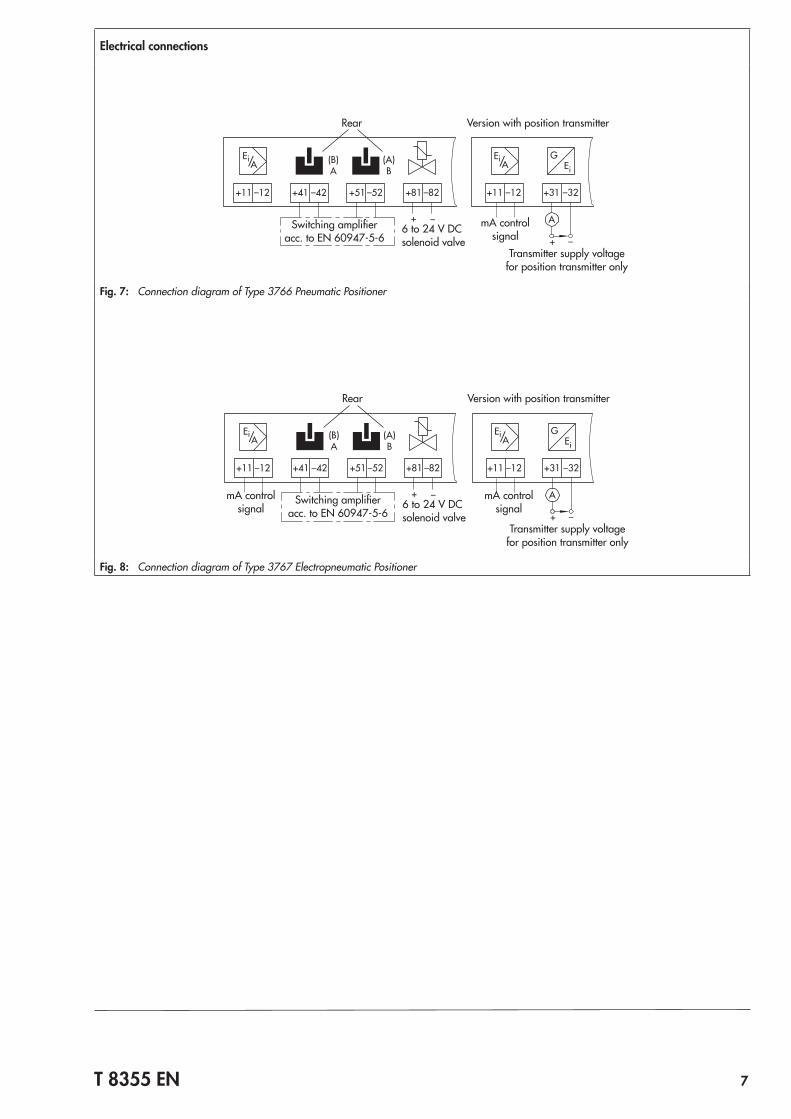
Electrical connections
+41 –42 +51 –52 +81 –82 +31 –32
GEi
+ –
+ –
(B)A
(A)B
A
+11 –12 +11 –12
Ei/Ei/ AA
mA control signal6 to 24 V DC
solenoid valveTransmitter supply voltage
for position transmitter only
Rear Version with position transmitter
Switching amplifier acc. to EN 60947-5-6
Fig. 7: Connection diagram of Type 3766 Pneumatic Positioner
+41 –42 +51 –52 +81 –82 +31 –32
GEi
+ –
+ –
(B)A
(A)B
A
+11 –12 +11 –12
Ei/Ei/ AA
mA control signal
mA control signal6 to 24 V DC
solenoid valveTransmitter supply voltage
for position transmitter only
Rear Version with position transmitter
Switching amplifier acc. to EN 60947-5-6
Fig. 8: Connection diagram of Type 3767 Electropneumatic Positioner

8 T 8355 EN
ArticlecodeforType 3766PneumaticPositionerPneumaticpositioner Type 3766- x x x 0 1 x x x x 1 x 0 x 0
Explosion protection
Without 0 2
II 2G Ex ia IIC T6 according to ATEX 1
CSA/FM intrinsically safe/non incendive 3
Ex ia/Ex n I/IIC T6 IP 65 IECEx TSA Australia 6
II 3G Ex nA II T6 acc. to ATEX 8
Additional equipment
Without 0
Inductive limit contacts 2x SJ2-SN 2
(Analog position transmitter 4 to 20 mA) 1) 6 0 0
3/2-way solenoid valve
Without 0
6 V DC 2
12 V DC 3
24 V DC 4
Pneumatic connections
¼-18 NPT 1
ISO 228/1-G ¼ 2
Electrical connections
Without (no additional equipment or solenoid valve) 0 0 0 0
Plastic cable gland M20 x 1.5, blue 1 0 0
Plastic cable gland M20 x 1.5, black 2 0 0
Cable gland M20 x 1.5, nickel-plated brass 2 1 3
Housing version
Die-cast aluminum 0
CrNiMo steel 2
Temperature range
Standard 0
Low-temperature version
Tmin ≥ –50 °C; optional limit contacts, solenoid valve 2 1 3
Special versions
Without 0 0 0
GOST Ex approval 0Ex ia IIC T8 X 1 0 1 0
1) Available until March 2011Device functioning only as analog position transmitter: 3766-x60 000xxx00 000 0

T 8355 EN 9
ArticlecodeforType 3767ElectropneumaticPositionerElectropneumatic positioners Type 3767- x x x 0 1 x x x x x x 0 0 0
Explosion protection
Without 0 2
II 2G Ex ia IIC T6 according to ATEX 1
CSA/FM intrinsically safe/non incendive 3
II 3G Ex nA II T6 acc. to ATEX 8
Additional equipment
Without 0
Inductive limit contacts 2x SJ2-SN 2
(Analog position transmitter 4 to 20 mA) 1) 6 0 0
3/2-way solenoid valve
Without 0
6 V DC 2
12 V DC 3
24 V DC 4
Type of mounting
Standard range spring 0 1
Pneumatic connections
¼-18 NPT 1
ISO 221/1-G ¼ 2
Electrical connections
Plastic cable gland M20 x 1.5, blue 1 0
Plastic cable gland M20 x 1.5, black 2 0
Cable gland M20 x 1.5, nickel-plated brass 2 1
Housing version
Die-cast aluminum 1
CrNiMo steel 2
Reference variable
4 to 20 mA 1
0 to 20 mA 2
1 to 5 mA 3
Temperature range
Standard 0
Low-temperature version
Tmin ≥ –45 °C; optional limit contacts, solenoid valve 2 1 2
Special versions
Without 0 0 0
1) Available until March 2011

10 T 8355 EN
Dimensions in mm
28
1429
150
164
19.5
37
68185
76
Supply(9)Output(36)
Direct attachment to Type 3277 Actuator
Attachment according toDIN EN 60534and NAMUR
Attachment to rotary actuators(with pneumatic reversing amplifier)
36N1 = 113N2 = 200
5856
68185
29
164
76
150
50
44
19.5
393568
185
164
29
50
46 7650
150
82
56 66
28.5
28.5
Output 1(A1)
Output 2(A2)
Supply (Z)
Fulcr
um

T 8355 EN 11
Ordering textType 3766 Pneumatic Positioner or Type 3767 Electropneumatic PositionerAccessories – NPT adapter for electrical connections – Range spring 2 – Filter check valve in housing with G ¼ thread
– Polyamide, IP 65 degree of protection – 1.4301, IP 65 degree of protection – Polyamide, NEMA 4 degree of protection – 1.4301, NEMA 4 degree of protection
Additionalspecifications – Without/with pressure gauges for signal pressure and sup-
ply air – For mounting on the control valve
– Adjusted reference variable – Direction of action: increasing/increasing or increas-
ing/decreasing – Positioners with inductive proximity switches:
– Metal tag outside the inductive field: contact closed – Metal tag inside the inductive field: contact open
– Direct attachment to Type 3277 Actuator (120 to 700 cm²) – Attachment according to IEC 60534-6 (NAMUR)
– Travel: ... mm, if applicable, rod diameter: … mm – Attachment to Type 3278 Rotary Actuator (160 or
320 cm²) – Attachment to rotary actuators according to VDI/
VDE 3845 – Single acting or double acting
– Linear or equal percentage characteristic – Opening angle 70°/75°/90°
Refer to the Mounting and Operating Instructions u EB 8355-1 (for Type 3766) or u EB 8355-2 (for Type 3767) concerning the mounting parts required when the positioner is delivered separately and not mounted onto a control valve.

Specifications subject to change without notice
SAMSON AG · MESS- UND REGELTECHNIK Weismüllerstraße 3 · 60314 Frankfurt am Main, Germany Phone: +49 69 4009-0 · Fax: +49 69 4009-1507 [email protected] · www.samson.de T8355EN 20
16-1
2-21
· En
glish