series 3725 type 3725 electropneumatic positioner · series 3725 electropneumatic positioner type...
TRANSCRIPT

Series 3725Electropneumatic PositionerType 3725
Mounting andOperating Instructions
EB 8394 EN (1300-1621)Firmware version 1.0xEdition February 2012
Fig. 1 · Type 3725 Positioner

2 EB 8394 EN
WARNING!indicates a hazardous situation which, if notavoided, could result in death or seriousinjury.
NOTICEindicates a property damage message.
Note: Supplementary explanations,information and tips
Definitions of the signal words used in these instructions

Contents Page
1 Safety instructions . . . . . . . . . . . . . . . . . . . . . . . . . . . 6
2 Article code . . . . . . . . . . . . . . . . . . . . . . . . . . . . . . 7
3 Design and principle of operation. . . . . . . . . . . . . . . . . . . . 83.1 Technical data. . . . . . . . . . . . . . . . . . . . . . . . . . . . . 10
4 Attachment to the control valve – Mounting parts and accessories . . . 124.1 Direct attachment . . . . . . . . . . . . . . . . . . . . . . . . . . . 144.1.1 Type 3277-5 Actuator . . . . . . . . . . . . . . . . . . . . . . . . . 144.1.2 Type 3277 Actuator . . . . . . . . . . . . . . . . . . . . . . . . . . 174.2 Attachment according to IEC 60534-6 . . . . . . . . . . . . . . . . . 204.3 Attachment to Type 3372 Actuator (V2001) . . . . . . . . . . . . . . 234.4 Attachment to rotary actuators . . . . . . . . . . . . . . . . . . . . . 244.5 Mounting parts and accessories . . . . . . . . . . . . . . . . . . . . 26
5 Connections . . . . . . . . . . . . . . . . . . . . . . . . . . . . . . 285.1 Pneumatic connections . . . . . . . . . . . . . . . . . . . . . . . . . 285.1.1 Signal pressure gauges . . . . . . . . . . . . . . . . . . . . . . . . 285.1.2 Supply pressure . . . . . . . . . . . . . . . . . . . . . . . . . . . . 285.2 Electrical connections . . . . . . . . . . . . . . . . . . . . . . . . . 29
6 Operation. . . . . . . . . . . . . . . . . . . . . . . . . . . . . . . 326.1 Operator controls . . . . . . . . . . . . . . . . . . . . . . . . . . . 32
7 Start-up – Settings. . . . . . . . . . . . . . . . . . . . . . . . . . . 337.1 Enabling configuration. . . . . . . . . . . . . . . . . . . . . . . . . 347.2 Setting the volume restriction Q . . . . . . . . . . . . . . . . . . . . 357.3 Adapting the display. . . . . . . . . . . . . . . . . . . . . . . . . . 357.4 Entering the opening direction . . . . . . . . . . . . . . . . . . . . . 367.5 Defining the direction of action. . . . . . . . . . . . . . . . . . . . . 367.6 Limiting the signal pressure. . . . . . . . . . . . . . . . . . . . . . . 367.7 Setting other parameters . . . . . . . . . . . . . . . . . . . . . . . 377.8 Initialization . . . . . . . . . . . . . . . . . . . . . . . . . . . . . . 387.9 Zero calibration . . . . . . . . . . . . . . . . . . . . . . . . . . . . 397.10 Manual mode . . . . . . . . . . . . . . . . . . . . . . . . . . . . . 407.11 Reset . . . . . . . . . . . . . . . . . . . . . . . . . . . . . . . . . 41
EB 8394 EN 3
Contents

7.12 Faults . . . . . . . . . . . . . . . . . . . . . . . . . . . . . . . . . 42
8 Code list . . . . . . . . . . . . . . . . . . . . . . . . . . . . . . . 43
9 Maintenance . . . . . . . . . . . . . . . . . . . . . . . . . . . . . 47
10 Servicing explosion-protected devices . . . . . . . . . . . . . . . . . 47
11 Dimensions in mm . . . . . . . . . . . . . . . . . . . . . . . . . . 4811.1 Fixing levels according to VDI/VDE 3845 (September 2010) . . . . . . 49
Test certificates . . . . . . . . . . . . . . . . . . . . . . . . . . . . 50
4 EB 8394 EN
Contents

EB 8394 EN 5
Firmware revisions
Firmware revisions
1.02 (previous) 1.03 (new)
Internal revisions
1 Safety instructions
For your own safety, follow these instructions concerning the mounting, start up and opera-tion of the positioner:
� The positioner is to be mounted, started up or operated only by trained and experi-enced personnel familiar with the product.According to these Mounting and Operating Instructions, trained personnel refers toindividuals who are able to judge the work they are assigned to and recognize possi-ble dangers due to their specialized training, their knowledge and experience as wellas their knowledge of the relevant standards.
� Explosion-protected versions of this positioner may only be operated by personnelwho have undergone special training or instructions or who are authorized to workon explosion-protected devices in hazardous areas.
� Any hazards that could be caused by the process medium, the operating pressure, thesignal pressure or by moving parts of the control valve are to be prevented by meansof the appropriate measures.
� If inadmissible motions or forces are produced in the actuator as a result of the supplypressure, the supply pressure must be restricted by means of a suitable supply pres-sure reducing station.
� Proper shipping and appropriate storage are assumed.
To avoid damage to any equipment, the following also applies:
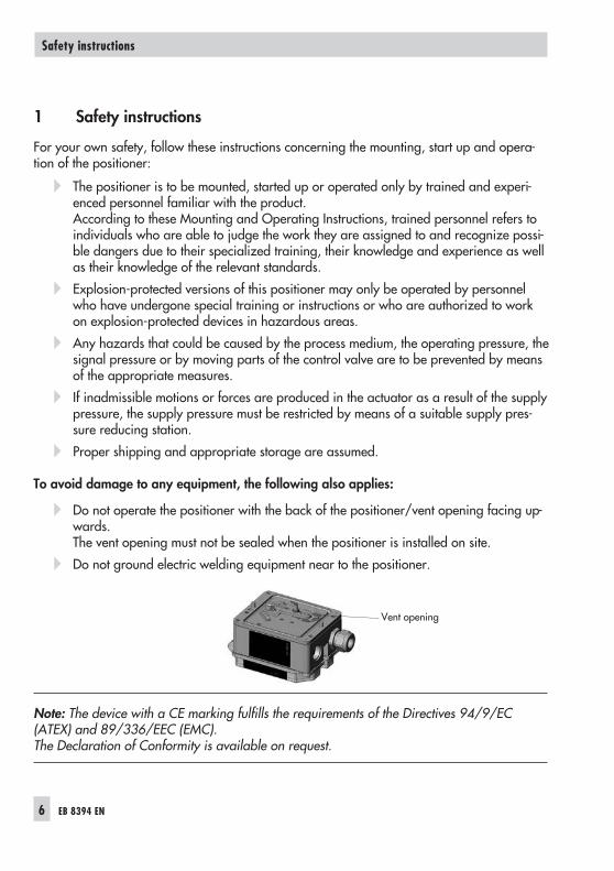
� Do not operate the positioner with the back of the positioner/vent opening facing up-wards.The vent opening must not be sealed when the positioner is installed on site.
� Do not ground electric welding equipment near to the positioner.
Note: The device with a CE marking fulfills the requirements of the Directives 94/9/EC(ATEX) and 89/336/EEC (EMC).The Declaration of Conformity is available on request.
6 EB 8394 EN
Safety instructions
Vent opening

2 Article code
EB 8394 EN 7
Article code
Positioner Type 3725- x x x 0 0 0 0 0 0 0 9 9 9 9
With LCD and autotune, 4 to 20 mA reference variable
Explosion protection*
Without 0 0 0
II 2 G Ex ia IIC T4 acc. to ATEX 1 1 0 0
* Other approvals in preparation

3 Design and principle ofoperation
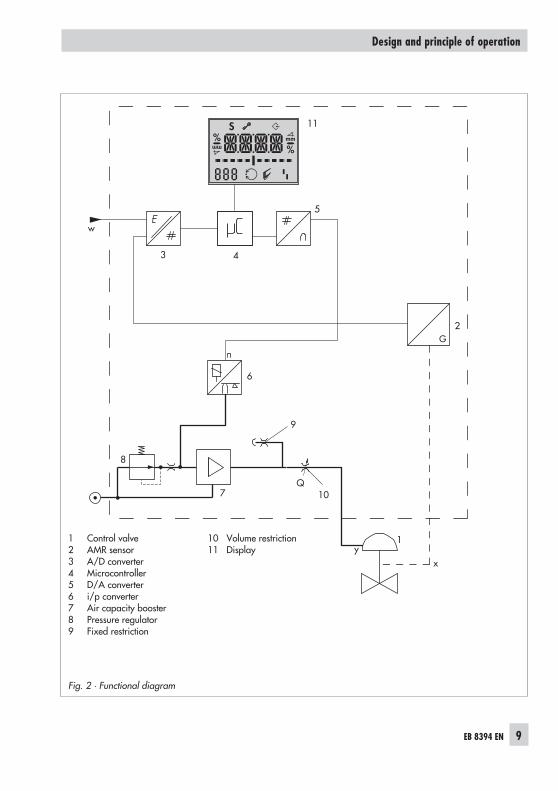
The electropneumatic positioner is mountedon pneumatic control valves. It is used to as-sign the valve stem position (controlled vari-able x) to the control signal (reference vari-able w). The electric control signal receivedfrom a control system is compared to thetravel or rotational angle of the control valveand a signal pressure (output variable y) isproduced for the pneumatic actuator.
The positioner consists of an anisotropicmagnetoresistive (AMR) sensor (2), an ana-log i/p converter (7) with a downstreambooster and the electronics unit withmicrocontroller (4).
The travel or opening angle is measured bythe pick-up lever connected to a magnet anda non-contact AMR sensor (2) installed inthe housing and the electronics.
The motion of the pick-up lever causes thedirection of the magnetic field to change.This change is sensed by the AMR sensor.The microprocessor determine the momen-tary valve position from this information.
The position of the valve is transmitted to themicrocontroller (4) over the A/D converter(3). The PD control algorithm in the micro-processor (4) compares this actual positionto the 4 to 20 mA control signal (referencevariable) after it has been converted by theA/D converter (3).
In case of a system deviation, the operationof the i/p converter (6) is changed so thatthe actuator (1) is filled or vented by thedownstream air capacity booster (7).
The pneumatic air capacity booster (7) andthe pressure regulator (8) are supplied withsupply air.The output signal pressure supplied by thebooster can be limited to 2.4 bar by soft-ware.
The volume restriction Q (10) is used to opti-mize the positioner by adapting it to the ac-tuator size.
Tight-closing function
The pneumatic actuator is completely filledwith air or vented as soon as the referencevariable falls below 1 % or exceeds 99 %(see end positions set over parameter codesP10 and P11).
Air to open (ATO): P10 � ON; P11 � OFFAir to close (ATC): P10 � OFF; P11 � ON
8 EB 8394 EN
Design and principle of operation
EB 8394 EN 9
Design and principle of operation
%
Smm
%mm
Q
3 4
11
6
7
8
10
1
w
9
xy
2
5
Fig. 2 · Functional diagram
1 Control valve2 AMR sensor3 A/D converter4 Microcontroller5 D/A converter6 i/p converter7 Air capacity booster8 Pressure regulator9 Fixed restriction
10 Volume restriction11 Display

3.1 Technical data
10 EB 8394 EN
Technical data
Type 3725 Positioner
Travel, adjustable Direct attachment to Type 3277 Actuator: 3.75 to 30 mmAttachment acc. to IEC 60 534-6-1 (NAMUR): 3.75 to 50 mmAttachment to Type 3372 Actuator: 15/30 mmAttachment to rotary actuators: 24 to 100°
Referencevariable w
Signal range 4 to 20 mA · Two-wire device with reverse polarity protection
Split rangeoperation 4 to 11.9 mA and 12.1 to 20 mA
Static destructionlimit �33 V
Minimum current 3.8 mA
Load impedance � 6 V (corresponds to 300 � at 20 mA)
Supply air
Supply pressure 1.4 to 7 bar (20 to 105 psi)
Air qualityacc. to
ISO 8573-1 (2001)
Max. particle size and density: Class 4 · Oil content: Class 3Pressure dew point: Class 3 or at least 10 K below the lowest ambient temperatureto be expected
Signal pressure (output) 0 bar up to the capacity of the supply pressure · Can be limited to approx. 2.4bar by software
Characteristics 3 characteristics for globe valves · 9 characteristics for rotary valves
Hysteresis � 0.3 %
Sensitivity � 0.1 %
Transit time < 0.5 s not permissible for initialization, adaptation using volume restriction
Direction of action w/x reversible
Air consumption � 100 ln/h with a supply pressure up to 6 bar and a signal pressure of 0.6 bar
Air outputcapacity
Actuator pressurized At �p = 6 bar: 8.5 mn³/h · At �p = 1.4 bar: 3.0 mn³/h · KVmax (20 °C) = 0.09
Actuator vented At �p = 6 bar: 14.0 mn³/h · At �p = 1.4 bar: 4.5 mn³/h · KVmax (20 °C) = 0.15
Permissible ambient temperature –25 to +80 °CLimits in test certificates additionally apply for explosion-protected devices.
Influences
Temperature � 0.15 %/10 K
Supply air None
Vibrations � 0.25 % up to 2000 Hz and 4 g according to IEC 770
Electromagnetic compatibility Complying with the requirements of EN 61000-6-2, EN 61000-6-3, EN 61326-1and NAMUR Recommendation NE 21
Electrical connections One M20x1.5 cable gland for 6 to 12 mm clamping rangeCage clamp terminals for 0.2 to 1.5 mm² wire cross-sections
Explosion protection II 2 G Ex ia IIC T4
Degree of protection IP 66
EB 8394 EN 11
Technical data
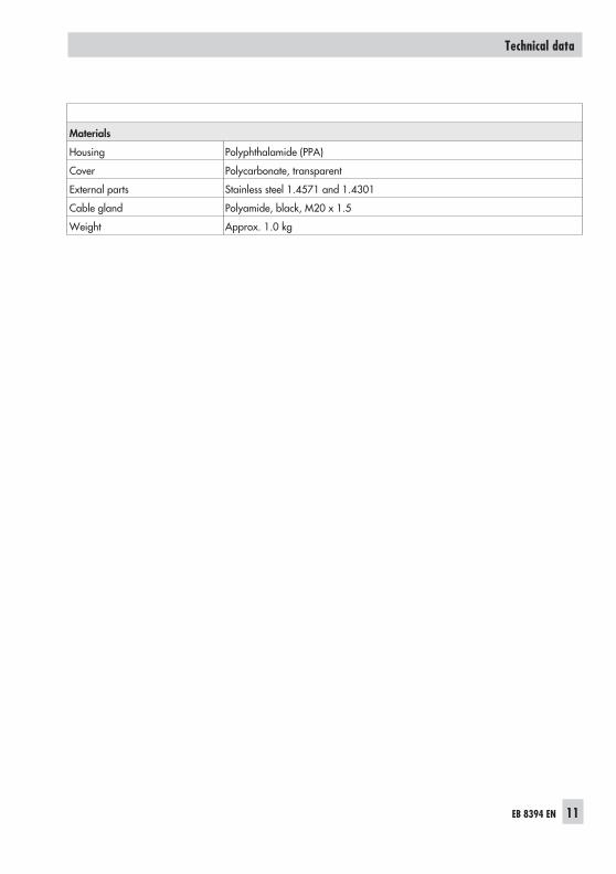
Materials
Housing Polyphthalamide (PPA)
Cover Polycarbonate, transparent
External parts Stainless steel 1.4571 and 1.4301
Cable gland Polyamide, black, M20 x 1.5
Weight Approx. 1.0 kg

4 Attachment to the controlvalve – Mounting parts andaccessories
WARNING!Attach the positioner, keeping the followingsequence:1. Mount the positioner on the control valve2. Connect the supply air3. Connect the electrical power4. Perform the start-up settings
The positioner is suitable for the followingtypes of attachment:
� Direct attachment to SAMSONType 3277 Actuator
� Attachment to actuators according toIEC 60534-6 (NAMUR)
� Attachment to Type 3372 Linear Actua-tor (V2001 Valve Series)
� Attachment to rotary actuators accordingto VDI/VDE 3845
NOTICEAttach the positioner to the control valve,observing the following instructions to avoiddamaging the positioner.– Use only the mounting parts/accessories
listed in the table (section 4.5). Observethe type of attachment!
– Observe the assignment between leverand pin position!
Lever and pin position
The positioner is adapted to the actuatorand to the rated travel by the lever on the
back of the positioner and the pin insertedinto the lever.
The travel tables show the maximum adjust-ment range at the positioner. The travel thatcan be implemented at the valve is addition-ally restricted by the selected fail-safe posi-tion and the required compression of the ac-tuator springs.
The positioner is standard equipped with thelever M (pin position 35).
NOTICEWhen undoing the lever, e.g. with a screw-driver, do not move the shaft by moving thelever past the mechanical stops. Otherwise,the internal stops may be damaged.
12 EB 8394 EN
Attachment to the control valve – Mounting parts and accessories
Fig. 3 · Lever M with pin position 35
Fig. 4 · Stop for lever

EB 8394 EN 13
Attachment to the control valve – Mounting parts and accessories
Travel tables
Note: The lever M is included in the scope of delivery.
Direct attachment to Type 3277-5 and Type 3277 Actuators
Actuator size Rated travel Adjustment range at positioner Requiredlever
Assignedpin position[cm²] [mm] Min. Travel Max.
120 7.5 5.3 to 15.0 M 25
120/240/350 15 7.5 to 21.2 M 35
355/700 30 10.6 to 30.0 M 50
Attachment according to IEC 60534-6 (NAMUR)
SAMSON Type 3271 Actuator Travel of other valves [mm] Requiredlever
Assignedpin position
Actuator size[cm²]
Rated travel[mm]
min. max.
120 7.5 3.75 10.6 S 17
120 7.5 5.3 25.0 M 25
120/240/350 155.0 35.0 M 35
700 7.5
700 15 10.8 50.0 M 50
Attachment to rotary actuators according to VDI/VDE 3845
Rotary actuators Requiredlever
Assignedpin positionMin. Opening angle Max.
24 to 100° M 90°

4.1 Direct attachment
4.1.1 Type 3277-5 Actuator
Refer to Table 1 on page 26 for requiredmounting parts and accessories.
Note the travel table on page 13!
Actuator with 120 cm²
Depending on the type of positioner attach-ment, the signal pressure is routed either leftor right of the yoke through a bore to theactuator diaphragm.
Depending on the fail-safe action of the ac-tuator "Actuator stem extends" or "Actuatorstem retracts" (valve closes or opens if thesupply air fails), the switchover plate (9)must first be attached to the actuator yoke.Align the switchover plate with the corre-sponding symbol for left or right attachmentaccording to the marking (view looking ontothe switchover plate).
1. Mount connecting plate (6) or pressuregauge bracket (7) with pressure gaugesonto the positioner, making sure bothseal rings (6.1) are seated properly.
2. Insert the screw (4) on the back of thepositioner into the hole below it (parkposition) (see Fig. 6) and seal the signalpressure output on the connecting plate(6) or on the pressure gauge bracket (7)with the stopper (5) included in the ac-cessories.
3. Place follower clamp (3) on the actuatorstem, align and screw tight so that themounting screw is located in the grooveof the actuator stem.
4. 15 mm travel: Keep the follower pin (2)at lever M (1) on the back of thepositioner in the pin position 35 (deliv-ered state).7.5 mm travel: Remove the follower pin(2) from the pin position 35, reposition itin the hole for pin position 25 and screwtight.
5. Insert formed seal (15) into the groove ofthe positioner housing.
6. Place positioner on the actuator in sucha manner that the follower pin (2) restson top of the follower clamp (3). Duringwhich, press on the ribbed area shownin Fig. 5 to lock the pick-up lever in thetop position.The lever (1) must rest on the followerclamp with spring force.Mount the positioner on the actuator us-ing the two fixing screws.
7. Mount cover (11) on the other side.Make sure that the vent plug pointsdownwards when the control valve is in-stalled to allow any condensed waterthat collects to drain off.
14 EB 8394 EN
Attachment to the control valve – Mounting parts and accessories
Fig. 5 · Locking the pick-up lever in position
EB 8394 EN 15
Attachment to the control valve – Mounting parts and accessories
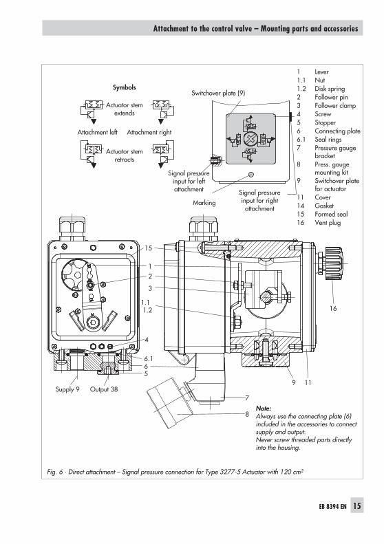
Symbols
Actuator stemextends
Attachment left Attachment right
Actuator stemretracts
1 Lever1.1 Nut1.2 Disk spring2 Follower pin3 Follower clamp4 Screw5 Stopper6 Connecting plate6.1 Seal rings7 Pressure gauge
bracket8 Press. gauge
mounting kit9 Switchover plate
for actuator11 Cover14 Gasket15 Formed seal16 Vent plug
Switchover plate (9)
Signal pressureinput for right
attachmentMarking
Signal pressureinput for leftattachment
Note:Always use the connecting plate (6)included in the accessories to connectsupply and output.Never screw threaded parts directlyinto the housing.
9 11Supply 9 Output 38
56
7
3
21
15
6.1
1.11.2
8
4
16
Fig. 6 · Direct attachment – Signal pressure connection for Type 3277-5 Actuator with 120 cm²

Additional solenoid valve
If a solenoid valve is additionally mountedonto the actuator, the signal pressure port atthe back of the positioner must be sealed. Todo this, unscrew the screw located in themiddle hole (screw in park position) andscrew it into the signal pressure port to sealit.
In this case, the signal pressure must berouted from the signal pressure output to theactuator over the connecting plate (6) orpressure gauge bracket (7). The connectingplate (accessories for the actuator) replacesthe switchover plate (9).
Note: The switchover plate or connectingplate are accessories for the actuator(120 cm²) listed in Table 1 on page 26.
16 EB 8394 EN
Attachment to the control valve – Mounting parts and accessories
Fig. 7 · Signal pressure port and screwpark position
Screw plug (4)(signal pressure port)
Park position
Mounting screw

4.1.2 Type 3277 Actuator
Refer to Table 2 on page 26 for the requiredmounting parts as well as the accessorieswith their order numbers.Note the travel table on page 13!
Note: The actuators with 240 to 700 cm² ef-fective areas are described on the followingpages.
EB 8394 EN 17
Attachment to the control valve – Mounting parts and accessories
Fig. 8 · Type 3277 Actuator with Type 3725Positioner (direct attachment)

Actuators with 240 to 700 cm²
The positioner can be mounted either on theleft or right side of the yoke. The signal pres-sure is routed to the actuator over the con-nection block (12), for actuators withfail-safe action "Actuator stem extends" in-ternally through a bore in the valve yokeand for "Actuator stem retracts" through ex-ternal piping.
1. Place follower clamp (3) on the actuatorstem, align it and screw tight so that themounting screw is located in the grooveof the actuator stem.
2. For actuators 240 and 350 cm² with15 mm travel, keep the follower pin (2)in pin position 35.For actuators with 355 or 700 cm², re-move the follower pin (2) at lever M (1)on the back of the positioner from pinposition 35, reposition it in the bore forpin position 50 and screw tight.
3. Insert formed seal (15) in the groove ofthe positioner housing.
4. Place positioner on the actuator in sucha manner that the follower pin (2) restson top of the follower clamp (3). Duringwhich, press on the ribbed area to lockthe pick-up lever in the top position(Fig. 9).The lever (1) must rest on the followerclamp with spring force.Mount the positioner on the actuator us-ing the two mounting screws.
5. Make sure that the tip of the gasket (16)projecting from the side of the connec-tion block (12) is positioned above theactuator symbol that corresponds with
the actuator with fail-safe action "Actua-tor stem extends" or "Actuator stem re-tracts". If necessary, remove the threemounting screws and the cover. Then re-position the gasket (16) turned by 180°.
6. Place the connection block (12) with theassociated seal rings against thepositioner and the actuator yoke andfasten using the screw (12.1).For actuators with fail-safe action "Actu-ator stem retracts", additionally removethe stopper (12.2) and fit on the externalsignal pressure piping.
7. Mount cover (11) on the other side.Make sure that the vent plug pointsdownwards when the control valve is in-stalled to allow any condensed waterthat collects to drain off.
18 EB 8394 EN
Attachment to the control valve – Mounting parts and accessories

EB 8394 EN 19
Attachment to the control valve – Mounting parts and accessories
1 Lever1.1 Nut1.2 Disk spring2 Follower pin3 Follower clamp11 Cover12 Connection block12.1 Screw12.2 Stopper or connection for
external piping15 Formed seal16 Gasket
2
10 15 1 2 3 11
1.11.2
12.11216
16
12.2SUPPLY
A
Ansicht A
1
Fig. 9 · Direct attachment – Signal pressure connection for Type 3277 Actuator with 240 to 700 cm²
View A

4.2 Attachment according toIEC 60534-6
The positioner is attached to the controlvalve with a NAMUR bracket (10).
Refer to Table 3 on page 26 for the requiredmounting parts as well as the accessorieswith their order numbers.Note the travel table on page 13!
1. Screw the two bolts (14) to the bracket(9.1) of the stem connector (9), place thefollower plate (3) on top and use thescrews (14.1) to tighten.
2. Mount NAMUR bracket (10) using theM8 screw (11) and toothed lock washerdirectly to the yoke bore.Align the NAMUR bracket (10) accord-ing to the embossed scale so that the slotof the follower plate (3) is centrallyaligned with the NAMUR bracket at midvalve travel.
3. Mount connecting plate (6) or pressuregauge bracket (7) with pressure gauges(8) on the positioner, making sure bothseal rings (6.1) are seated properly.
4. Place positioner on the NAMUR bracketin such a manner that the follower pin(2) rests in the slot of the follower plate(3). Adjust the lever (1) correspondingly.Screw the positioner to the NAMURbracket using both its mounting screws.
20 EB 8394 EN
Attachment to the control valve – Mounting parts and accessories

EB 8394 EN 21
Attachment to the control valve – Mounting parts and accessories
10
11
14.1
3
14
11.21.12
9.1
9
6.1 6 7 8
Fig. 10 · Attachment according to IEC 60534-6 (NAMUR)
1 Lever1.1 Nut1.2 Disk spring2 Follower pin3 Follower plate6 Connecting plate6.1 Seal rings7 Pressure gauge bracket8 Pressure gauge
mounting kit9 Stem connector9.1 Bracket10 NAMUR bracket11 Screw14 Bolt14.1 Screw

22 EB 8394 EN
Attachment to the control valve – Mounting parts and accessories

4.3 Attachment to Type 3372Actuator (V2001)
The Type 3725 Positioner is already in-cluded in the scope of delivery for V2001valve series (Type 3372 Actuator).
The attachment is briefly described below toallow conversion work to be performed.
Actuator 120 and 350 cm², stem extends
The signal pressure is routed through thecorresponding port in the support element tothe actuator diaphragm.
Thread the screw on the positioner into thehole below (park position) (Fig. 7).
Actuator 120 and 350 cm², stem retracts
The signal pressure is routed through pipingat the side of the support element to the ac-tuator diaphragm.
Attachment including solenoid valve
The signal pressure is routed from the outputport of the positioner to the solenoid valveand through a corresponding hole on thesupport element to the actuator diaphragm.
EB 8394 EN 23
Attachment to the control valve – Mounting parts and accessories
Type 3372 Actuator, 350 cm²
Type 3372 Actuator, 120 cm²
Fig. 11 · Attachment to Type 3372 Actuator

4.4 Attachment to rotaryactuators
The positioner is mounted to the rotary actu-ator using a mounting bracket.
Refer to Table 4 on page 27 for the re-quired mounting parts as well as the acces-sories.
Before attaching the positioner onto theSAMSON Type 3278 Rotary Actuator(160 cm²) or VETEC Type S160 Actuator,first mount the adapter (13) to the free endof the shaft end using four screws (11, 12).
NOTICEOn attaching the positioner as described be-low, it is imperative that the actuator's direc-tion of rotation is observed.
1. Place follower clamp (3) on the slottedactuator shaft or adapter (13).
2. Place coupling wheel (4) with flat sidefacing the actuator on the followerclamp (3). Refer to Fig. 12 to align slotso that it matches the direction of rota-tion when the valve is in its closed posi-tion.
3. Fasten the coupling wheel (4) and fol-lower clamp (3) tightly onto the actuatorshaft using screw (4.1) and disk spring(4.2).
4. Mount connecting plate (6) or pressuregauge bracket (7) with pressure gaugesto the positioner, making sure bothO-rings are seated properly.
5 Fasten the mounting bracket (10) to theactuator using four screws (10.1).
6. Unscrew the standard follower pin (2)from the positioner's lever M (1). Use themetal follower pin (Ø5) included in themounting kit and screw tight into thebore for pin position 90°.
7. Place positioner on the mounting bracket(10) and screw tight. Considering theactuator's direction of rotation, adjust le-ver (1) so that it engages in the slot ofthe coupling wheel (4) with its followerpin (see Fig. 13). It must be guaranteedthat the lever (1) is parallel to the longside of the positioner when the actuatoris at half its angle of rotation.
8. Stick the scale label on the couplingwheel so that the arrow tip indicates theclosed position and it can be easily readwhen the valve is installed.
24 EB 8394 EN
Attachment to the control valve – Mounting parts and accessories
Fig. 12 · Direction of rotation

EB 8394 EN 25
Attachment to the control valve – Mounting parts and accessories
8050
60
30
66.178
11.11.2
2
4.1
3
10.1
10
5
4
4.2
Attachment according to VDI/VDE 3845, level 2
30
5080
66.178
11.11.2
2
4.1
3
10.1
10
5
13
10.1
4
4.2
Attachment to SAMSON Type 3278 Rotary Actuator(160 cm²) or VETEC Type S160 Actuator
1 Lever1.1 Nut1.2 Disk spring2 Follower pin3 Follower clamp4 Coupling wheel4.1 Screw4.2 Disk spring5 Actuator shaft
6 Connecting plate6.1 Seal rings7 Pressure gauge
bracket8 Pressure gauge
mounting kit10 Mounting bracket10.1 Screw13 Adapter
Fig. 13 · Attachment to rotary actuators

4.5 Mounting parts and accessories
26 EB 8394 EN
Attachment to the control valve – Mounting parts and accessories
Table 1 · Direct attachment to Type 3277-5 Actuator (see section 4.1) Order no.
Mounting parts Mounting parts for actuators 120 cm² or smaller 1402-0239
Accessories forthe actuator
Switchover plate for Type 3277-5xxxxxx.01 Actuator 1400-6822
Connecting plate for additional attachment of, e.g. a solenoid valve: G 18 1400-6820
Accessories forthe positioner
Connecting plate (6)G ¼ 1402-0235
¼ NPT 1402-0236
Pressure gauge bracket (7)G ¼ 1402-0237
¼ NPT 1402-0238
Pressure gauge mounting kit (8) up to max. 6 bar(output/supply)
St. steel/brass 1400-6950
St. steel/st. steel 1400-6951
Table 2 · Direct attachment to Type 3277 (see section 4.1.2) Order no.
Mounting parts Attachment to actuators 240, 350, 355 and 700 cm² 1402-0240
Accessories
Connection block with seals and screwG ¼ 1402-0241
¼ NPT 1402-0242
Pressure gauge mounting kit up to max. 6 bar(output/supply)
St. steel/brass 1400-6950
St. steel/st. steel 1400-6951
Table 3 · Attachment to NAMUR ribs according to IEC 60534-6 (see section 4.2)
Travel [mm] Lever For actuators Order no.
3.75 to 50Without,already onpositioner
Actuators from other manufacturers and Type 3271 with120 to 700 cm² 1402-0330
Accessories
Connecting plateG ¼ 1402-0235
¼ NPT 1402-0236
Pressure gauge bracketG ¼ 1402-0237
¼ NPT 1402-0238
Pressure gauge mounting kit up to max. 6 bar(output/supply)
St. steel/brass 1400-6950
St. steel/st. steel 1400-6951

EB 8394 EN 27
Attachment to the control valve – Mounting parts and accessories
Table 4 · Attachment to rotary actuators (see section 4.4) Order no.
Mounting parts Attachment according to VDI/VDE 3845 (level 2*), 20 mm shaft height 1402-0243
Attachment according to VDI/VDE 3845 (level 2*), 30 mm shaft height 1402-0244
Attachment to VETEC Type S160 Actuator or SAMSON Type 3278 RotaryActuator, 160 cm² (level 2*) 1402-0294
Accessories
Connecting plateG ¼ 1402-0235
¼ NPT 1402-0236
Pressure gauge bracketG ¼ 1402-0237
¼ NPT 1402-0238
Pressure gauge mounting kit up to max. 6 bar(output/supply)
St. steel/brass 1400-6950
St. steel/st. steel 1400-6951
*) Designation since 2010: For sizes AA1 and AA2 (see section 11.1)
Table 5 · General accessories Order no.
Cable gland M20 x 1.5, blue 8808-1012
Brief instruc-tions insidecover
DE/EN (delivered state) 0190-6173/0190-6174

5 Connections
5.1 Pneumatic connections
NOTICEThe threaded connections in the positionerhousing are not designed for the direct con-nection of pneumatic fittings!
The screw fittings must be screwed into theconnecting plate, the pressure gauge mount-ing block or the connection block from theaccessories.The pneumatic connections are optionallydesigned as a bore with ¼ NPT or G ¼thread.The customary fittings for metal and copperpipes or plastic hoses can be used.
Keep the length of the line as short as possi-ble to avoid delays in control signal trans-mission.
Note: The supply air must be dry and freefrom oil and dust.The maintenance instructions for upstreampressure reducing stations must be ob-served.Blow through all air pipes and hoses thor-oughly prior to connecting them.
If the positioner is attached directly to theType 3277 Actuator, the connection of thepositioner's output pressure to the actuator isfixed.
For attachment according to IEC 60534-6(NAMUR), the signal pressure can be routedto either the top or bottom diaphragm
chamber of the actuator, depending on theactuator's fail-safe action "Actuator stem ex-tends" or "Actuator stem retracts".
For rotary actuators, the manufacturer'sspecifications for connection apply.
5.1.1 Signal pressure gauges
To monitor the supply air (Supply) and sig-nal pressure (Output), we recommendmounting pressure gauges (see accessoriesin section 4.5).
5.1.2 Supply pressure
The required supply air pressure depends onthe bench range and the actuator's operat-ing direction (fail-safe action).The bench range is registered on the name-plate either as spring range or signal pres-sure range depending on the actuator. Thedirection of action is marked FA or FE, or bya symbol.
Actuator stem extends FA (Air to open)
Fail-safe position "Valve Closed"(for globe and angle valves):
Required supply pressure = Upper benchrange value + 0.2 bar, minimum 1.4 bar.
Actuator stem retracts FE (Air to close)
Fail-safe position "Valve Open"(for globe and angle valves):For tight-closing valves, the maximum signalpressure pstmax is roughly estimated as fol-lows:
pstmax = F + d pA
2
4� �
�
� � [bar]
28 EB 8394 EN
Connections

d = Seat diameter [cm]�p = Differential pressure across the valve
[bar]A = Actuator diaphragm area [cm²]F = Upper bench range value [bar]
If there are no specifications, calculate asfollows:
Required supply pressure =Upper bench range value + 1 bar.
Note: The signal pressure at the output (38)of the positioner can be restricted to approx.2.4 bar by setting parameter code P9 toON.
5.2 Electrical connections
DANGER!Risk of electric shock and/orthe formation of an explosiveatmosphere!
– For electrical installation, observe the rel-evant electrotechnical regulations andthe accident prevention regulations thatapply in the country of use.
– The following regulations apply tomounting and installation in hazardousareas: EN 60079-14: 2008 Explosiveatmospheres – Part 14: Electrical instal-lations design, selection and erection.
Risk of explosion due to electrostaticcharging
Avoid electrostatic charging of the plastichousing when mounting and servicing thepositioner in hazardous areas.
NOTICE– Adhere to the terminal assignment!
Switching the assignment of the electricalterminals may cause the explosion pro-tection to become ineffective!
– Do not loosen enameled screws in or onthe housing.
– The maximum permissible values speci-fied in the national EC type examinationcertificates apply when interconnectingintrinsically safe electrical equipment(Ui, Ii, Pi, Li and Ci).
EB 8394 EN 29
Connections

Selecting cables and wires:
Observe Clause 12 of EN 60079-14: 2008when installing intrinsically safe circuits.The Subclause 12.2.2.7 applies when run-ning multi-core cables containing more thanone intrinsically safe circuit.
In particular, the radial thickness of the con-ductor insulation for common insulation ma-terials, such as polyethylene, must have aminimum radial thickness of 0.2 mm.
The diameter of an individual wire in afine-stranded conductor must not be smallerthan 0.1 mm. Protect the conductor endsagainst splicing, e.g. by using wire-end fer-rules.
Equipment for use in zone 2
In equipment operated with type of protec-tion Ex nA II (non-sparking equipment) ac-cording to EN 60097-15: 2003, circuitsmay be connected, interrupted or switchedwhile energized only during installation,maintenance or repair.
Cable entries
The M20 x 1.5 cable gland is designed fora clamping range of 6 to 12 mm.The cage clamp terminals hold wirecross-sections of 0.2 to 1.5 mm² and addi-tionally have test connections for 1 mmprobe tips.
To remove the cable, press the tip of ascrewdriver into the cage clamp terminaland pull out the wire at the same time.
The wires for the reference variable must beconnected to the terminals 11 and 12 lo-cated in the housing. Only use a currentsource!
NOTICEThe static destruction limit of the positioner isat � 33 V.Do not allow the input signal to fall belowthe lowest permissible value of 3.8 mA forpositioner operation.
30 EB 8394 EN
Connections
Fig. 14 · Cage clamp terminal with test contact

Accessories:
Plastic cable gland M20 x 1.5:– Black Order no. 8808-1011– Blue Order no. 8808-1012
EB 8394 EN 31
Connections
+11 -12
Fig. 15 · Electrical connections
mA control signal

6 Operation
Three capacitive keys and a LCD are used tooperate the positioner.To adapt the air capacity, the volume restric-tion must be adjusted (section 7.2).
6.1 Operator controls
Press or to select parameter codes(P0 to P20). Press to confirm the se-lected code.
NOTICEAny parameter code settings that have beenchanged are first saved in a non-volatilememory after the display has returned to thedisplay with status indication. Go to CodeP0 by pressing or or wait three min-utes until the display returns automatically.The icon on the display indicates that thechanged parameter settings have not yetbeen saved in the non-volatile memory.
Note: After changing settings in parametercodes P2, P3, P4, P8 and P9, the positionermust be re-initialized.
32 EB 8394 EN
Operation
%
Smm
%mm
Fig. 16 · Capacitive keys and display
Confirm
UpDown
Fail-safe position active
Parameter/error code
Unit
Bar graph for system deviation
Fault
Closed-loop operation
Settings not yet saved in anon-volatile memory
Manual mode
Operation locked

Volume restriction Q
The volume restriction is used to adapt theair delivery to the actuator size. Two fixedsettings are possible depending on how theair is routed to the actuator. Refer to sec-tion 7.2.
Display
Reading on display Meaning
ESC Cancel
Err Error
LOW w too small
MAN Manual mode
MAX Maximum range
RST Reset
INIT Initialization
ON/OFF Activated/deactivated
ZERO Zero calibration
Icons assigned to certain codes and func-tions are indicated on the display. The barelements indicate the system deviation thatdepends on the sign (+/–) and the value.One bar element appears per 1 % systemdeviation.
If the positioner has not yet been initialized,the lever position in degrees in relation tothe longitudinal axis is indicated. One barelement corresponds to approximately a 5°angle of rotation.If the fault indication icon appears onthe display, press or until ERR appe-ars on the display to view the error code(s)E0 to E15. Refer to section 7.11 for detailsand the code list in section 8).
7 Start-up – Settings
WARNING!Do not perform a start-up while the processis running.On applying supply air and the electric con-trol signal, the control valve may movethrough its entire travel range/rotational an-gle range depending on the setting.
� Connect the supply air (Supply 9).� Connect the 4 to 20 mA signal (terminals
+11/–12). Do not touch the key panel!
Note: After connecting the electrical signal(power supply), the positioner performs acalibration of the capacitive keys whichtakes approx. three seconds. During thistime, do not touch the key panel. Otherwise,the keys will not work properly.Disconnect and reconnect the electrical sig-nal to restart the calibration of keys.
LOW on the display indicates that the refer-ence variable is lower than 4 mA (0 %).
The positioner is ready for operation with itsdefault settings for most applications, pro-vided it has been mounted properly.
Note: The positioner needs to be initializedagain after the position of the volume re-striction has been changed.The positioner also needs to be initializedagain after the setting for the fail-safe posi-tion has been changed.
EB 8394 EN 33
Start-up – Settings

Display after connecting the electrical sig-nal
The fault indication icon and S (fail-safeposition) appear on the display when thepositioner has not yet been initialized. Thereading indicates the lever positioner in de-grees relative to the longitudinal axis.
� Code 0 appears on the display after con-necting the electrical signal to an initial-ized positioner. The positioner goes tothe last active operating mode.
7.1 Enabling configuration
Note: Before changing parameter settings,configuration must be enabled first by select-ing Code P19.
If no settings are entered within threeminutes, the enabled configuration functionbecomes invalid.
Press or until Code P19 appears.
Press to confirm selected code. P19blinks.
Press until OPEN appears on the display.
Press to confirm unlocking.
WARNING!During start-up the actuator stem moves.Do not touch the actuator stem or obstruct itto avoid risk of injury to hands or fingers.
If the left or right outer bar element blinks(reading > 30°), the permissible angle of ro-tation has been exceeded.
The positioner goes to the fail-safe position(SAFE).
Make sure that the lever and pin positionmatch the details as described in section 4.
Note: The positioner has a function to moni-tor the working range.If the lever moves too close to the mechani-cal stops (risk of mechanical damage), thepositioner vents the actuator and the valvemoves to its fail-safe position (S displayedtogether with error code E8).In this case, check the positioner attachment.Reset the displayed error code by selectingRST (see section 7.12).
34 EB 8394 EN
Start-up – Settings
S
Display when the positionerhas not yet been initialized
Enabling configurationover Code 19
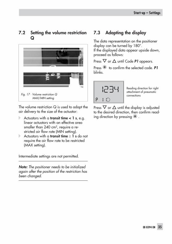
7.2 Setting the volume restrictionQ
The volume restriction Q is used to adapt theair delivery to the size of the actuator:
� Actuators with a transit time < 1 s, e.g.linear actuators with an effective areasmaller than 240 cm², require a re-stricted air flow rate (MIN setting).
� Actuators with a transit time 1 s do notrequire the air flow rate to be restricted(MAX setting).
Intermediate settings are not permitted.
Note: The positioner needs to be initializedagain after the position of the restriction hasbeen changed.
7.3 Adapting the display
The data representation on the positionerdisplay can be turned by 180°.If the displayed data appear upside down,proceed as follows:
Press or until Code P1 appears.
Press to confirm the selected code. P1blinks.
Reading direction for rightattachment of pneumaticconnections
Press or until the display is adjustedto the desired direction, then confirm read-ing direction by pressing .
EB 8394 EN 35
Start-up – Settings
Fig. 17 · Volume restriction QMAX/MIN setting

7.4 Entering the openingdirection
� AIR TO OPEN/ATO applies to a valveopening as the signal pressure increases.
� AIR TO CLOSE/ATC applies to a valveclosing as the signal pressure increases
The signal pressure is the pneumatic pres-sure at the output of the positioner appliedto the actuator.
Enable configuration (refer to section 7.1).
Standard ATO
Press or until Code P2 appears.
Press to confirm the selected code.P2 blinks.
Press or to select the required fail-safe position.
Press to confirm setting.
Note: The changed opening direction firstbecomes effective after the positioner hasbeen re-initialized.
7.5 Defining the direction ofaction
The direction of action is set to increas-ing/increasing by default.
For checking purposes:After successfully completing initialization,the positioner display should read 0 % when
the valve is closed and 100 % when thevalve is open.
If necessary, the direction of action can bechanged either before or after initialization.
The following correlation applies:
Valve CLOSED OPEN
Display 0 % 100 %
ATO�� 4 mA 20 mA
�� 20 mA 4 mA
ATC�� 4 mA 20 mA
�� 20 mA 4 mA
� � Increasing/increasing� � Increasing/decreasing
7.6 Limiting the signal pressure
If the maximum actuator force may causedamage to the valve, the signal pressuremust be limited.
Set Code P9 to ON. This limits the signalpressure to approx. 2.4 bar.
Enable configuration at the positioner beforeactivating the pressure limit function (refer tosection 7.1)
36 EB 8394 EN
Start-up – Settings

7.7 Setting other parameters
The following table lists all the parametercodes and their default settings.If you want to change the default setting of aparameter, proceed in the same manner aspreviously described.
Note: The selected parameter code remainsactive until you change the setting or exit theparameter code.
More details concerning the parametercodes can be found in section 8.
EB 8394 EN 37
Start-up – Settings
Parameter codesCodes marked with * can be changed without having to re-initialize the positioner[...] Default setting
P0 Display with status indication P11 End position w > [OFF]
P1 Reading direction P14 Display of reference variable w
P2* Fail-safe position [ATO] P15 INIT Start initialization
P3* Pin position [35] P16 ZERO Start zero calibration
P4* Nominal range [MAX] P17 Manual mode
P5 Characteristic [1] P18 Reset
P6 Reference variable [4 to 20 mA] P19 Enable configuration
P7 w/x direction of action [>>] P20 Read firmware
P8* Gain Kp [50]
P9* Pressure limit 2.4 bar [OFF]
P10 End position w < [ON]
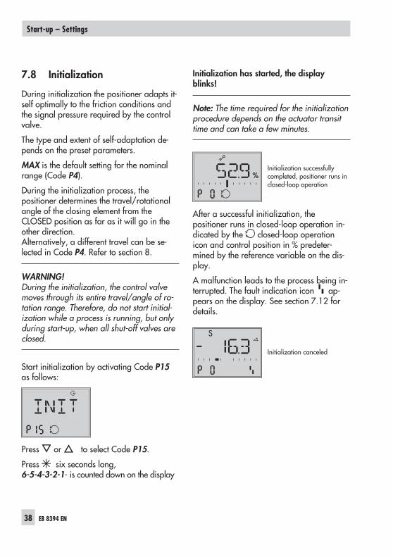
7.8 Initialization
During initialization the positioner adapts it-self optimally to the friction conditions andthe signal pressure required by the controlvalve.
The type and extent of self-adaptation de-pends on the preset parameters.
MAX is the default setting for the nominalrange (Code P4).
During the initialization process, thepositioner determines the travel/rotationalangle of the closing element from theCLOSED position as far as it will go in theother direction.Alternatively, a different travel can be se-lected in Code P4. Refer to section 8.
WARNING!During the initialization, the control valvemoves through its entire travel/angle of ro-tation range. Therefore, do not start initial-ization while a process is running, but onlyduring start-up, when all shut-off valves areclosed.
Start initialization by activating Code P15as follows:
Press or to select Code P15.
Press six seconds long,6-5-4-3-2-1- is counted down on the display
Initialization has started, the displayblinks!
Note: The time required for the initializationprocedure depends on the actuator transittime and can take a few minutes.
Initialization successfullycompleted, positioner runs inclosed-loop operation
After a successful initialization, thepositioner runs in closed-loop operation in-dicated by the closed-loop operationicon and control position in % predeter-mined by the reference variable on the dis-play.
A malfunction leads to the process being in-terrupted. The fault indication icon ap-pears on the display. See section 7.12 fordetails.
Initialization canceled
38 EB 8394 EN
Start-up – Settings
%
S

Canceling initialization
The initialization can be canceled by press-ing .
Canceling initialization
� ESC blinks on the display.
� Press to confirm the code.
Note: This code must be confirmed by press-ing . Otherwise, the code remains active.
Example 1: A positioner that has not yetbeen initialized goes to the fail-safe positionafter the initialization process has been can-celed.
Example 2: The initialized positioner goes toAUTO mode after the re-initialization pro-cess has been canceled. The settings of theprevious initialization are used.
A new initialization can be started directlyafterwards.
7.9 Zero calibration
In case of inconsistencies in the closing posi-tion of the valve, e.g. with soft-sealed plugs,it might be necessary to recalibrate zero.
Enable configuration (refer to section 7.1).
Start the zero calibration by activatingCode P16 as follows:
Press or until Code P16 appears.
Press button six seconds long,6-5-4-3-2-1 is counted down on the display.
Zero calibration has started, the displayblinks!
The positioner moves the control valve to theCLOSED position and recalibrates the inter-nal electric zero point.
When the zero calibration has been suc-cessfully completed, the positioner returns toclosed-loop operation (display with statusindication).
EB 8394 EN 39
Start-up – Settings

Canceling zero calibration
The zero calibration can be canceled bypressing .
� ESC blinks on the display
� Press to confirm the code.
Note: This code must be confirmed by press-ing . Otherwise, this code remains active.
The positioner returns to closed-loop opera-tion without performing a zero calibration.
A new zero calibration can be started di-rectly afterwards.
7.10 Manual mode
The valve position can be moved as followsusing the Manual mode function:
Enable configuration (refer to section 7.1).
Press or until Code P17 appears.
Press for six seconds, the display countsdown 6-5-4-3-2-1.
P17 blinks.
The manual set point (w man) is indicatedon the display of an initialized positioner.
The lever position in degrees in relation tothe longitudinal axis is indicated on the dis-play of a positioner that has not been ini-tialized.
Press or to change the manual setpoint.
Initialized positioner
The manual mode starts using the last setpoint of the automatic mode, ensuring abumpless changeover.The bar elements on the display indicate the
40 EB 8394 EN
Start-up – Settings
%

system deviation between the manual andautomatic set point while manually movingthe valve in Code P17.The manual set point is adjusted in steps of0.1 %. You can move the valve controlledwithin its range.
Positioner that has not been initialized
Keep or pressed to move the valvemanually.
The valve is only moved in one direction un-controlled. The bar elements on the displayindicate the change in direction.
Press to deactivate the manual adjust-ment function.
Note: The Manual mode function can onlybe exited as described. The positioner doesnot automatically exit this function and re-turn to the display with status indication.
7.11 Reset
The positioner is in closed-loop operationafter the initialization has been successfullycompleted.
A reset causes an initialization to be can-celed and all parameters settings are reset tothe default settings (refer to the code list insection 8).
Enable configuration (refer to section 7.1).
Press or until Code P18 appears.
Press for six seconds, the display countsdown 6-5-4-3-2-1.RST blinks.
After the positioner has been reset, the dis-play automatically returns to status indica-tion (P0). In this display, the angle is indi-cated in degree relative to the longitudinalaxis.
EB 8394 EN 41
Start-up – Settings
S

7.12 Faults
On the occurrence of a fault, the faultindication icon appears at the bottom ofthe display.
If the fault indication icon appears after aparameter code setting has been changed,this indicates that these settings do notmatch the values determined during initial-ization. See Code E1 (refer to section 8).
Press or past Code P 0 or P 20, therespective error code E0 to E15 togetherwith ERR appear on the display.Refer to the code list in section 8 for thecause of the errors and the recommendedaction.
Example:If, for instance, a travel has been enteredover Code P4 (nominal range) which islarger than the maximum valve travel possi-ble, the initialization process would be inter-rupted (error code E2) because the ratedtravel would not have been reached (errorcode E6). The valve moves to the fail-safeposition (S indicated on the display).
Display of the faultindication
The nominal range (Code P4) must bechanged and the positioner re-initialized toremedy this problem.
Reset error codes
The error codes E0 and E8 can be reset asfollows:
Press or until the error code appears.
Press , ESC appears.
Press or , RST appears.
Press to reset error.
The resetting procedure can be canceled bypressing when ESC appears.
42 EB 8394 EN
Start-up – Settings
S
SS

8 Code list
Code Display, values[default setting] Description
Parameter codes Codes marked with * can be changed without having to re-initialize the positioner
P0 Status indication mode of the display showing basic informationThe reading indicates the valve position or the angle of rotation in %when the positioner is initialized.The position of the lever in relation to the mid-axis is indicated in de-grees (°) when is pressed and the positioner has not yet been ini-tialized.
P1 * Reading direction The reading direction of the display is turned by 180°.
P2 ATO / ATC[ATO]
Parameter to adapt the positioner to how the control valve functions:ATO – Air to open (valve CLOSED in fail-safe position)ATC – Air to close (valve OPEN in fail-safe position)
P3 Pin position25/[35]/50/90°
The follower pin must be inserted into the correct pin positionaccording to the valve travel/angle of rotation (select as per traveltables on page 13).
P4 Nominal range[MAX]
Values withdefault setting [35]:e.g.7.5/8.92/10.6/12.6/15.0/17.8/21.2/25.2/30 mm
The possible adjustment range can be selected in stages dependingon the selected pin position:17 from 3.75 to 10.625 from 5.3 to 15.035 from 7.5 to 21.250 from 10.6 to 30.0For 90° Maximum range only, if P3 = 90°
MAX Maximum possible travel
P5 * Characteristic0 to 8[1]
Characteristic selection: Characteristic 0, 1, 2 for globe valves,Characteristic 0 to 8 with rotary actuators(P3 = 90°)
0 Linear1 Equal percentage2 Reverse equal percentage3 SAMSON butterfly valve, linear4 SAMSON butterfly valve, equal percentage5 VETEC rotary plug valve, linear6 VETEC rotary plug valve, equal percentage7 Segmented ball valve, linear8 Segmented ball valve, equal percentage
EB 8394 EN 43
Code list
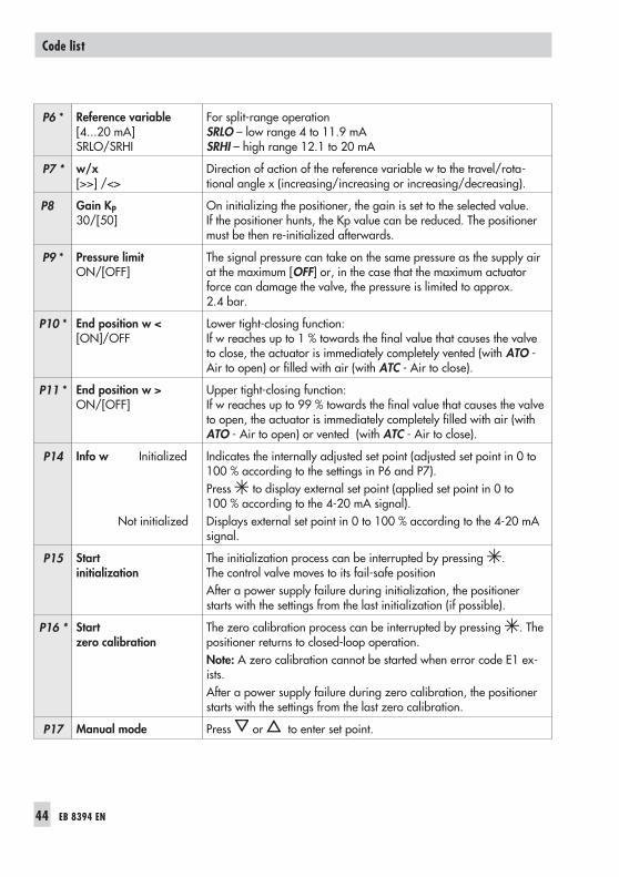
P6 * Reference variable[4...20 mA]SRLO/SRHI
For split-range operationSRLO – low range 4 to 11.9 mASRHI – high range 12.1 to 20 mA
P7 * w/x[>>] /<>
Direction of action of the reference variable w to the travel/rota-tional angle x (increasing/increasing or increasing/decreasing).
P8 Gain KP30/[50]
On initializing the positioner, the gain is set to the selected value.If the positioner hunts, the Kp value can be reduced. The positionermust be then re-initialized afterwards.
P9 * Pressure limitON/[OFF]
The signal pressure can take on the same pressure as the supply airat the maximum [OFF] or, in the case that the maximum actuatorforce can damage the valve, the pressure is limited to approx.2.4 bar.
P10 * End position w <[ON]/OFF
Lower tight-closing function:If w reaches up to 1 % towards the final value that causes the valveto close, the actuator is immediately completely vented (with ATO -Air to open) or filled with air (with ATC - Air to close).
P11 * End position w >ON/[OFF]
Upper tight-closing function:If w reaches up to 99 % towards the final value that causes the valveto open, the actuator is immediately completely filled with air (withATO - Air to open) or vented (with ATC - Air to close).
P14 Info w Initialized
Not initialized
Indicates the internally adjusted set point (adjusted set point in 0 to100 % according to the settings in P6 and P7).Press to display external set point (applied set point in 0 to100 % according to the 4-20 mA signal).Displays external set point in 0 to 100 % according to the 4-20 mAsignal.
P15 Startinitialization
The initialization process can be interrupted by pressing .The control valve moves to its fail-safe positionAfter a power supply failure during initialization, the positionerstarts with the settings from the last initialization (if possible).
P16 * Startzero calibration
The zero calibration process can be interrupted by pressing . Thepositioner returns to closed-loop operation.Note: A zero calibration cannot be started when error code E1 ex-ists.After a power supply failure during zero calibration, the positionerstarts with the settings from the last zero calibration.
P17 Manual mode Press or to enter set point.
44 EB 8394 EN
Code list

P18 Reset Parameters are reset to their default setting.The positioner can only return to closed-loop operation after it hasbe re-initialized.
P19 Enable configuration Enable configuration to change parameter settings.This function is automatically canceled when none of the keys arenot pressed within three minutes.
P20 Display firmware Installed firmware version is shown.The last four digits of the serial number are shown when ispressed.
Error codes
E0 Zero error(operational error)
Only with tight-closing function P10 w < set to ONThe zero point has shifted by more than 5 % compared to initializa-tion. The error may arise when the mounting position/linkage of thepositioner moves or when the valve seat trim is worn, especially withsoft-sealed plugs.
Recommended action Check valve and mounting of the positioner. If OK, perform a zerocalibration over Code P16 (see section 7.9)or reset the error code (see section 7.12).
E1 Displayed and INITvalues are not identical(operational error)
Parameter code settings were changed after the initialization hadbeen completed.
Recommended action Reset parameters or perform initialization.
E2 Positioner has not beeninitialized
Recommended action Set parameters and initialize the positioner over Code P15.
E3 KP setting(initialization error)
Positioner hunts.Volume restriction set incorrectly, too much gain.
Recommended action Check the volume restriction setting as described in section 7.2.Limit gain KP in Code P8. Re-initialize the positioner.
E4 Transit time is too fast(initialization error)
The transit times of the actuator determined during initialization areso short (under 0.5 second) that the positioner cannot adapt itselfwell enough.
Recommended action Check the volume restriction setting as described in section 7.2.Re-initialize the positioner.
EB 8394 EN 45
Code list
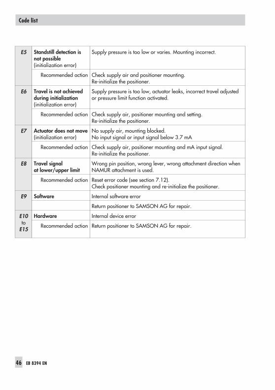
E5 Standstill detection isnot possible(initialization error)
Supply pressure is too low or varies. Mounting incorrect.
Recommended action Check supply air and positioner mounting.Re-initialize the positioner.
E6 Travel is not achievedduring initialization(initialization error)
Supply pressure is too low, actuator leaks, incorrect travel adjustedor pressure limit function activated.
Recommended action Check supply air, positioner mounting and setting.Re-initialize the positioner.
E7 Actuator does not move(initialization error)
No supply air, mounting blocked.No input signal or input signal below 3.7 mA
Recommended action Check supply air, positioner mounting and mA input signal.Re-initialize the positioner.
E8 Travel signalat lower/upper limit
Wrong pin position, wrong lever, wrong attachment direction whenNAMUR attachment is used.
Recommended action Reset error code (see section 7.12).Check positioner mounting and re-initialize the positioner.
E9 Software Internal software error
Return positioner to SAMSON AG for repair.
E10to
E15
Hardware Internal device error
Recommended action Return positioner to SAMSON AG for repair.
46 EB 8394 EN
Code list

9 Maintenance
The positioner does not require any mainte-nance.
There are filters with a 100 m mesh size inthe pneumatic connections for supply andoutput which can be removed and cleaned,if required.
The maintenance instructions of any up-stream supply air pressure reducing stationsmust be observed.
10 Servicing explosion-protecteddevices
If a part of the device on which the explo-sion protection is based needs to be ser-viced, the device must not be put back intooperation until a qualified inspector has as-sessed it according to explosion protectionrequirements, has issued an inspection cer-tificate or given the device a mark of confor-mity.
Inspection by a qualified inspector is not re-quired if the manufacturer performs a rou-tine test on the device prior to putting it backinto operation. The passing of the routinetest must be documented by attaching amark of conformity to the device. Replaceexplosion-protected components only byoriginal, routine-tested components from themanufacturer.
Devices that have already been operatedoutside hazardous areas and are intendedfor future use inside hazardous areas mustcomply with the safety requirements placedon serviced devices. Before being used in-
side hazardous areas, test the devices ac-cording to the specifications for servicingexplosion-protected devices.
EB 8394 EN 47
Maintenance

11 Dimensions in mm
48 EB 8394 EN
Dimensions in mm
1422
M 20x1.5
157.5
108
87
42
21
62.50
25
Fig. 18 · Dimensional drawing of Type 3725

11.1 Fixing levels according to VDI/VDE 3845 (September 2010)
Dimensions in mm
Size A B C �d Mmin �D *
AA1 80 30 20 5.5 for M5 96 50
AA2 80 30 30 5.5 for M5 96 50
* Flange type F05 according to DIN EN ISO 5211
EB 8394 EN 49
Dimensions in mm
A
M6
C
B
25
Mmin
Ød
ØD
Level 2 (bracket surface)
Level 1 (actuator surface)
Actuator

50 EB 8394 EN

EB 8394 EN 51

52 EB 8394 EN

EB 8394 EN 53

54 EB 8394 EN

EB 8394 EN 55

SAMSON AG · MESS- UND REGELTECHNIKWeismüllerstraße 3 · 60314 Frankfurt am Main · GermanyPhone: +49 69 4009-0 · Fax: +49 69 4009-1507Internet: http://www.samson.de EB 8394 EN 20
12-0
6