tube mill vs plant ect (od vs. id) bop od vs id ect testing 2014 r2.pdftube mill vs plant ect (od...
TRANSCRIPT

1
Tube Mill vs Plant ECT (OD vs. ID) – Addressing Manufacturing Related Tube Indications Authors: Dan Janikowski – Plymouth Tube Eric Wennerstrom – Babcock & Wilcox Co. (Intech) Iver Jacobson - True North Consulting
13th EPRI BOP Heat Exchanger NDE Symposium

2
NPP Tube Quality Expectations: - Typically quite lofty NPP Tube Quality Required by
Specifications: - Often fairly minimal
Heat Exchanger Tube Quality

3
Communication issues with tube supplier: “Tubes are 100% Eddy Current Tested” Utility engineers may incorrectly interpret this to mean:
1. Tube ID ECT they are familiar with from HX PM actions 2. Assume tube mill ECT flaw detection and sizing will be similar 3. Assume similar rejection/acceptance criteria as utility applies
Utility engineers involved with replacement HX tube
specification generally lack familiarity with tube mill OD ECT and other NDE options such as UT, as well as their impact on tube quality.
Heat Exchanger Tube Quality

4
Fabrication flaws/indications for seam-welded tubes: Raw Materials
– Laminations/inclusions – Break marks – Scratches
Seam Weld:
o Cracks o Mismatch o Inadequate deburring/rough edges at weld o Weld darts o Lack of penetration o Etc.
Heat Exchanger Tube Quality
5
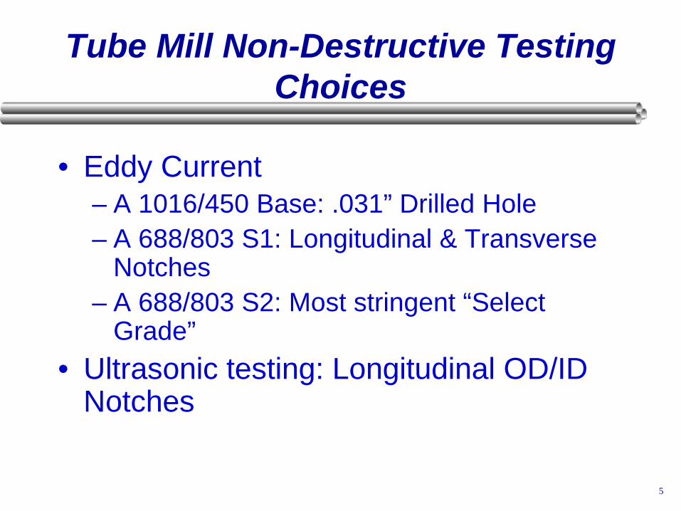
Tube Mill Non-Destructive Testing Choices
• Eddy Current – A 1016/450 Base: .031” Drilled Hole – A 688/803 S1: Longitudinal & Transverse
Notches – A 688/803 S2: Most stringent “Select
Grade” • Ultrasonic testing: Longitudinal OD/ID
Notches

6
Mill ECT –Strengths & Weaknesses
• Differential technique sensitive to abrupt imperfections (transverse)
• Signal is volume related • Can find non-through wall imperfections • Attenuation reduces sensitivity on ID
surface – results can be very different from ID testing
• Won’t detect gradually growing imperfections (longitudinal) – Gradual weld defects may not
provide rejectionable signal • Uses a single frequency that does not
allow depth sizing

7
Typical Tube Mill ECT • Uses encircling coil differential technique • Almost all use full magnetic saturation to eliminate
noise caused by delta ferrite in austenitic welds • If welded, most do testing either in-line on welding
mill • Some mills have capability to do off-line testing to
provide more flexibility • Mills will only use A1016/450 requirements unless
otherwise specified

8
A1016/ A450 ECT Testing
• Almost all mills choose a through-wall drilled hole not exceeding .031” (0.8 mm) diameter for heat exchanger sizes
• Tubing is centered by drilling multiple holes around circumference or rotating standard
• Recalibration is every 4 hours • There is no requirement to prove full ECT penetration! • Signals can be ignored from the following
imperfections provided they can be proven to not exceed .004” or 12.5% of minimum thickness: – Scratches, surface roughness, dings, straightener marks,
loose ID bead and cutting chips, steel die stamps, stop marks, tube reducer ripple, or chattered flash trim

9
A688/803-S1 ECT Testing
• Requires longitudinal and transverse OD and ID notches!
• Provides a test that is 6 to 10 dB more stringent than 0.031” drilled hole.
• Tubing is centered by rotating standard. • Recalibration is every 1/2 hours. • Full ECT penetration is proven by demonstrating ID
notches. • Tube with signals exceeding signals from either OD
notch shall be rejected! ID notches are often negotiated.
• Cannot be done in-line with welder.

10
A688/803-S2 ECT Testing
• Most requirements identical to A688/803-S1. • On most walls, notch width restriction is much more
stringent. • Provides a test that is about 6 dB more stringent than S1
on walls above 0.035” (0.9 mm). • Due to tube background noise, can usually be offered on
cold drawn tubing only.

11
Ultrasonic – Strengths & Weaknesses
• Sensitive to longitudinal defects • Signal related to reflected area of
imperfection • Defects do not need to have volume. • Sensitive to both OD and ID
imperfections • Imperfections do not need to be
through-wall • Acceptance criteria is often 12.5%
deep OD and ID longitudinal notches

12
Tube Mill NDE Tests
Pass / Fail Criteria – No Report: • Rejection threshold per ASTM
std unless other value in spec. • UT & pressure test also used for
tube quality

13
Utility HX Tube NDE
Baseline NDE inspection: • Quality “hand-off” to buyer • Pre-service benchmark of
indications: – Manufacturing indications
• Below rejection threshold at tube mill • Non-leaking (i.e. passed hydro)
– Assembly related indications • Allows future NDE inspections
to identify active vs inactive (i.e. service-related vs mfg-related)
• Basis to adjust plugging criteria

14
ID ECT has high detection capability for most flaws.
1. Numerous indications may exist in “new” tubes – Most – detected by tube mill NDE but below rejection limit – Some - not detected by tube mill NDE
2. Rejection threshold at tube mill may not be consistent
with tube plugging criteria used by utility – Indication “Passes” at tube mill – Same indication “Fails” utility plugging threshold
3. The reported depth of mfg flaws may be less accurate.
– The flaw type and shape may differ from the service-related flaw types on the ECT calibration standard
ID Eddy Current Testing at NPP

15
Objective / Purpose of utility NDE of HX Tubes:
Avoid Leaks = high reliability
To maximize HX service life and thermal performance margin, it is desirable to differentiate between:
Active tube damage (service related) vs.
Inactive Flaws/Indications (include mfg. flaws)
Tube fabrication flaws which pass tube mill NDE and testing are very unlikely to result in a leak, unless the flaw initiates an active degradation mechanism. In the vast majority of cases neither the mfg-related flaw type nor the service conditions support transition to active damage.
ID Eddy Current Testing at NPP

16
“Ideal World” 1. Preventatively plug tubes prior to leakage 2. Only plug tubes with credible failure risk 3. Avoid “unnecessary” tube plugging Historical over reliance only on % Through Wall (i.e. depth)
when making plugging decisions has resulted in many instances of plugging inactive MFG related indications. – Loss of thermal margin/efficiency – Reduced service life – False appearance of reliability risk – May result in more frequent NDE than justified by actual risk
ID Eddy Current Testing at NPP
17
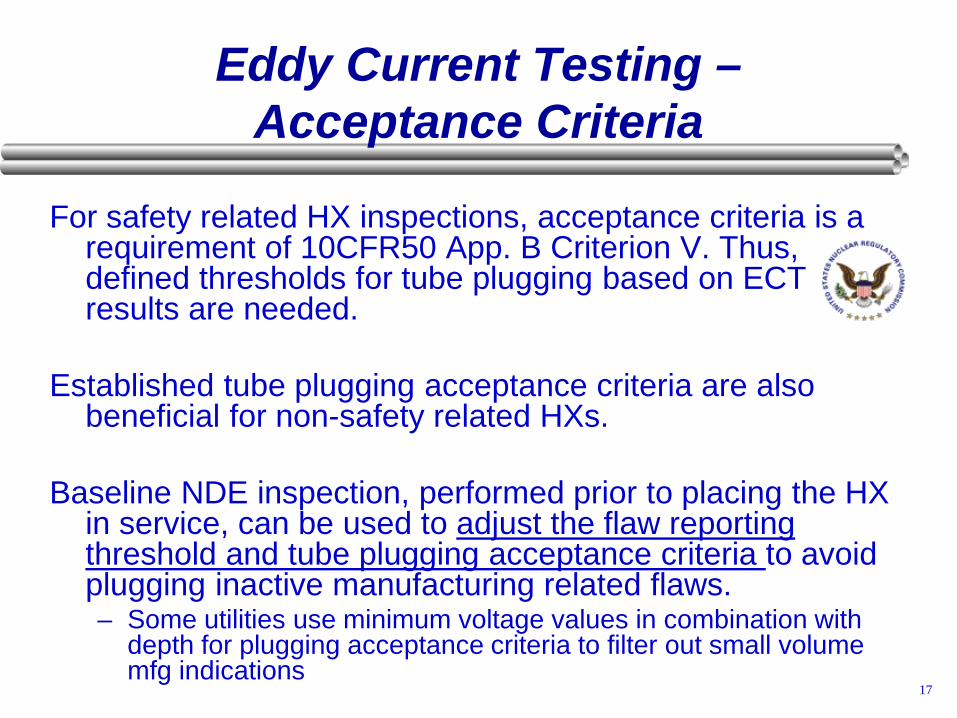
For safety related HX inspections, acceptance criteria is a requirement of 10CFR50 App. B Criterion V. Thus, defined thresholds for tube plugging based on ECT results are needed.
Established tube plugging acceptance criteria are also
beneficial for non-safety related HXs. Baseline NDE inspection, performed prior to placing the HX
in service, can be used to adjust the flaw reporting threshold and tube plugging acceptance criteria to avoid plugging inactive manufacturing related flaws. – Some utilities use minimum voltage values in combination with
depth for plugging acceptance criteria to filter out small volume mfg indications
Eddy Current Testing – Acceptance Criteria
18
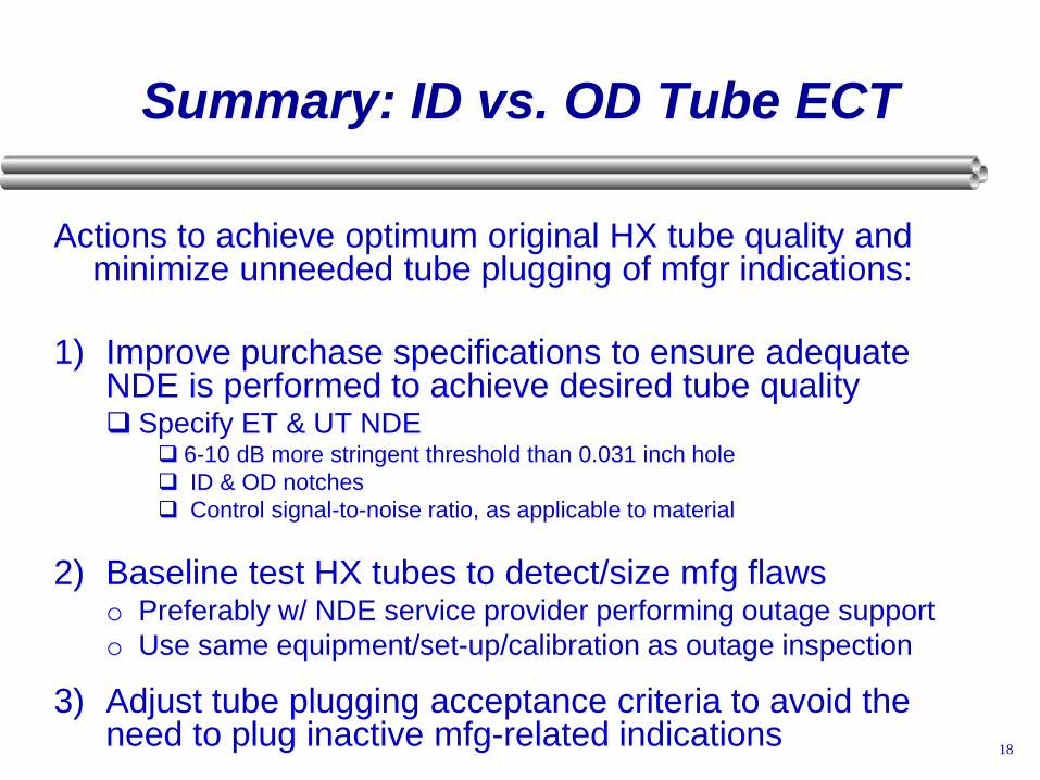
Actions to achieve optimum original HX tube quality and minimize unneeded tube plugging of mfgr indications:
1) Improve purchase specifications to ensure adequate
NDE is performed to achieve desired tube quality Specify ET & UT NDE
6-10 dB more stringent threshold than 0.031 inch hole ID & OD notches Control signal-to-noise ratio, as applicable to material
2) Baseline test HX tubes to detect/size mfg flaws o Preferably w/ NDE service provider performing outage support o Use same equipment/set-up/calibration as outage inspection
3) Adjust tube plugging acceptance criteria to avoid the need to plug inactive mfg-related indications
Summary: ID vs. OD Tube ECT