tremron keystone samples
DESCRIPTION
First Coast Pavers and TremronTRANSCRIPT

THE TREMRON GROUPKeystone® Collection& Installation Guide

2 Keystone Stonegate Country Manor / Top Right: Keystone Palazzo Stone
3
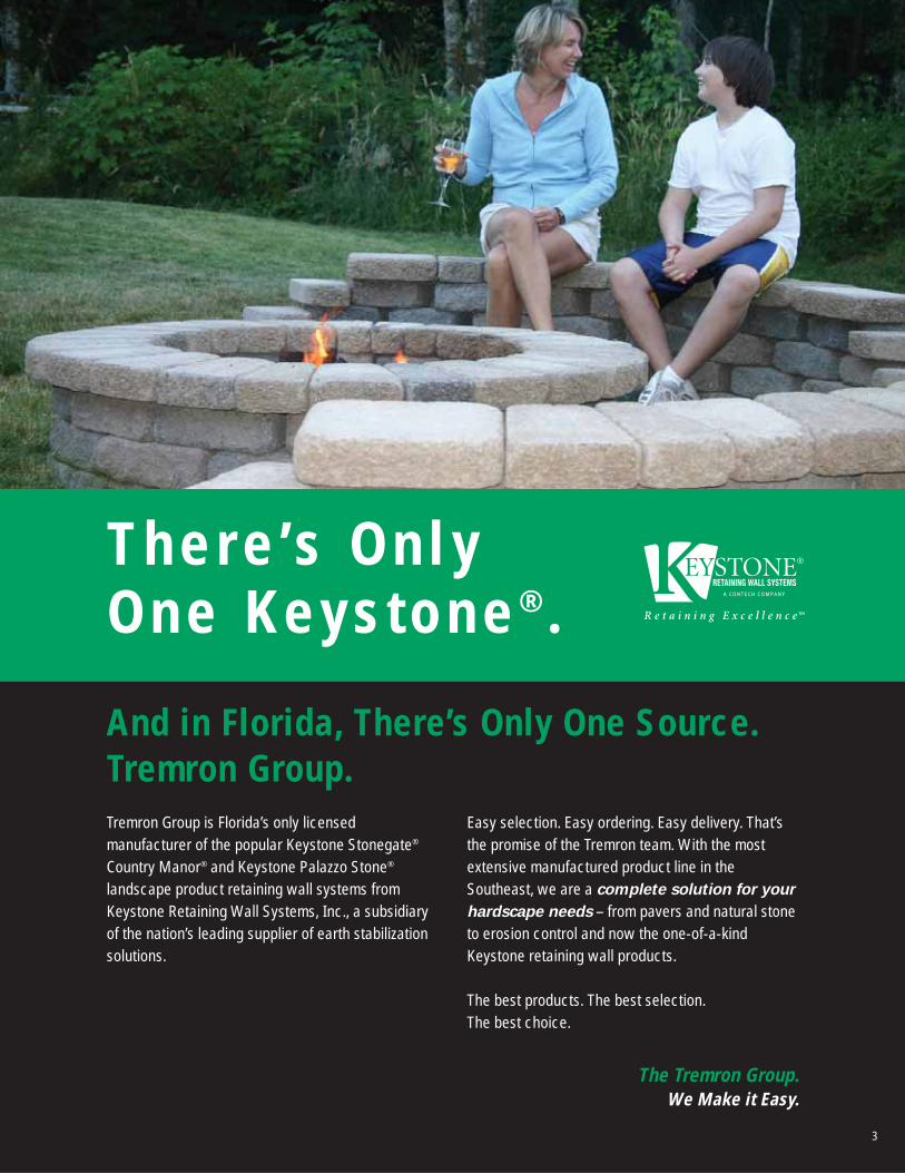
T h e r e ’s O n l y O n e K e y s t o n e ®.
And in Florida, There’s Only One Source.Tremron Group.Tremron Group is Florida’s only licensedmanufacturer of the popular Keystone Stonegate®
Country Manor® and Keystone Palazzo Stone®
landscape product retaining wall systems fromKeystone Retaining Wall Systems, Inc., a subsidiaryof the nation’s leading supplier of earth stabilizationsolutions.
Easy selection. Easy ordering. Easy delivery. That’sthe promise of the Tremron team. With the mostextensive manufactured product line in theSoutheast, we are a complete solution for your
hardscape needs – from pavers and natural stoneto erosion control and now the one-of-a-kindKeystone retaining wall products.
The best products. The best selection. The best choice.
The Tremron Group.We Make it Easy.

4 Top and Right: Keystone Stonegate Country Manor / Inset: Keystone Palazzo Stone
5

K e y s t o n eS t o n e g a t e ®
C o u n t r y M a n o r ®
Product shown in Oak Run.
6
Featuring the look of smooth, weatheredstone you might find in a quaint Europeantown, Keystone Stonegate Country Manor hasall the best features of the original KeystoneCountry Manor®, but with a twist!
Keystone Stonegate Country Manor’s smooth face looks like cut stone and presents amore refined look. Utilizing Keystone’s patented fiberglass pin connection method,Keystone Stonegate Country Manor offers the same freestanding wall options asKeystone Country Manor and is also suitable for larger, structural projects.
For castle or cottage, if you want the beauty of natural stone and sophisticated, easy-to-use technology, think Keystone Stonegate Country Manor.
tremrongroup.com

7
6"h x 10"d x 12"/10"w40 lbs.
6"h x 10"d x 6"/4"w25 lbs.
6"h x 10"d x 16"/14"w60 lbs.
Shade variation is inherent in all-natural materials. Colors may vary depending upon manufacturing location. Individual productmeasurements given are rounded. Contact your Tremron Sales Representative or visit our website for exact dimensions.
CAP UNIT3"h x 12"d x 10"w
22 lbs.
FIBERGLASS PINS5-1/4" total length
1-1/4" shoulder length1/2" diameter at pin shaft3/4" diameter at shoulder
we make it easy
Available colors:
Tan
Granite
Oak Run
Sante Fe
Timberwood
Keystone interlocking connectionand alignment pins are madefrom high strength pultrudedfiberglass. Minimum short beamshear strength is 6400 psi.
finished wall side
retained soil side
closed
alignmentopen
alignment
drainage fill 12" (300mm)
In addition to providing strength and beauty, Keystone Stonegate CountryManor can create signature hardscape designs that set your projectapart from all others. The ability to create freestanding walls allows forthe creation of barbeques, fireplaces, outdoor kitchens, bench seating,and the concealment of outdoor lighting and speaker systems. UseKeystone Stonegate Country Manor to provide detail and accent to alarge lawn or green space, add grandeur to a drive or walkway, or createa truly unique pool/patio area.

tremrongroup.com
8
The closed channel end at theunit bottom allows for finishedend aesthetics on 90° cor-ners, pilasters and wall end
conditions. As required for pininterlock, remove the solid closed
end of the receiving channel.Remove only if pin from unit belowstrikes this area.
The receiving channel on the bottomsurface of each unit connects overthe pins from the course below.Walls can be built with positivemechanical connection in 90°corners, curves and straight wallgeometry without loss of connectionor strength.
F e a t u r e s & B e n e f i t sThree or More Face Dimensions• Provides the greatest degree of random layout due to
variations from unit side dimensions.• Each unit has two side dimensions.
Colors• Keystone Stonegate Country Manor is produced in color
blends that enhance the natural stone-like appearance.
Three Textured Sides on Each Unit• Weathered or antiqued finish to provide a more natural stone
look to the units.• Allows each unit to be used in multiple positions within the
wall.• Each unit can be used as an exposed end unit or a 90° corner
unit.• Allows construction of small freestanding walls, parapet walls,
pilasters and columns in addition to retaining walls.
Shape• Each unit has a 90° angle and a tapered (angled) side, allowing
the units to be used in 90° corners, tight fitting straight linewalls, and radii at curves.
Units are Packaged in Sets• Eliminates the need for the contractor to pull from multiple
pallets to maintain random appearance.• Provides for a simple method of construction and a random
appearance to the wall system.
High Strength Pins with Shouldered Cap• Multiple pin positions allow for near vertical, 9.5° batter
(setback), and the opportunity to randomly pull a unit forwardto accent the wall.

we make it easy
9
Pattern &Appearance
“Rule of Thumb” for bondpattern between courses:Construct the wall using theunits as they come off eachshipping pallet. Randomly uti-lize the various unit shapestrying to avoid a repetition ofsame unit size frequencyalong a horizontal line (someunit repetition is unavoid-able).
Avoid stack bonding of unitjoints (vertical joint linebetween adjoining units) formore than two courses verti-cally.
If some units seem to have ablemish or too much textur-ing in a specific area, orientthem so the blemish facesthe soil side of the wall tohide imperfections or usethese units along the wallbase.
I n s t a l l a t i o n S t e p sS
TE
P 1
ST
EP
2S
TE
P 3
ST
EP
4S
TE
P 5
ST
EP
6
PREPARE THE BASE LEVELING PADRemove all surface vegetation and debris. Do not use this material as backfill. Afterselecting the location and length of the wall, excavate the base trench to the designedwidth and depth (min. 20" W x 12" D)[500mm x 300mm]. Start the leveling pad at the low-est elevation along wall alignment. Step up in 6" (150mm) increments with the base asrequired at elevation changes in the foundation. Level the prepared base with 6" (150mm)of well-compacted granular fill (gravel, road base, or 1/2" to 3/4" [10-20 mm] crushedstone). Compact to 95% Standard Proctor or greater. Do not use PEA GRAVEL or SANDfor leveling pad.
INSTALL THE BASE COURSEPlace the first course of Keystone Stonegate Country Manor units end to end (with frontcorners touching) on the prepared base. The long groove (receiving channel) on the unitshould be placed down and the three pin holes should face up, as shown. Make sureeach unit is level - side to side and front to back. Leveling the first course is critical foraccurate and acceptable results. For alignment of straight walls, use a string line alignedon the unit pin holes for accuracy. Minimum embedment of base course is 6" belowgrade.
INSERT THE FIBERGLASS PINSPlace the shouldered fiberglass pins into the holes of the Keystone Stonegate CountryManor Units (note: place one pin only per each grouping of three holes). Place pins in themiddle hole for near vertical alignment or the holes nearest the embankment for a 9.5° ±setback per course. According to wall requirements and design, the front pin hole(towards the face of the wall) can be used randomly to allow a forward projection of aspecific unit for accent and variation in the wall appearance.
INSTALL FILL & COMPACTIONOnce the pins have been installed, provide 1/2"- 3/4" (10-20mm) crushed stone drainagefill behind the units to a minimum depth of 12" (300mm). Fill open spaces between unitsand open cavities/cores with the same drainage material. Proceed to place backfill inmaximum 6" (150mm) layers (lifts) and compact to 95% Standard Proctor with the appro-priate compaction equipment. Do not use heavy ride-on compaction equipment within 3'(1m) from back of wall. Do not use jumping or ramming type compaction.
INSTALL ADDITIONAL COURSESPlace the next course of Keystone Stonegate Country Manor units over the fiberglasspins, fitting the pins into the long receiving channel recess of the units above (Note:Some removal of debris in the pin holes and channel may be necessary prior to place-ment). Push the Keystone Stonegate Country Manor units toward the face of the walluntil they make full contact with the pins. If pins do not connect with channel but align inopen core of upper unit, place drainage fill in core to provide unit interlock with pin. Fornear vertical alignment, center the unit above over the center placed pins below.
CAPPING THE WALLContinue all steps until ready to place the wall cap. Clean off the last course of KeystoneStonegate Country Manor in preparation for the cap or coping to finalize the wall. Withunits dry and clean, use construction adhesive (Keystone Kapseal™) for a mechanicalbond. Install the Keystone Stonegate Country Manor 3" (75mm) capping unit, architectur-al precast concrete or cut stone as a coping element. Cap may be flush or overhangingas required by aesthetics and design. Note: For taller, more critical walls, refer to geogridsoil reinforcement instructions on the following page.
Embedment
Unit embedment below thegrade line shall be a mini-mum of one unit buried,under all conditions, alongwith a general provision ofH/20 (wall height divided by20) for total wall embedmentof taller walls. Note H=totalheight of wall from top ofbase leveling pad to top ofwall.
Consult a qualified engineerfor sloping grade conditionsin front of wall or steepslopes and surcharge loadson top of wall.
Deeper embedment may berequired in areas prone tosurface scouring where baseerosion is possible, or inareas where freestandingwalls are desired and frostdepths require deeper foun-dations.

tremrongroup.com
10
G e o g r i d S o i lR e i n f o r c e m e n tTaller walls or walls supporting surcharge loads require the use ofgeogrid reinforcement material to reinforce a cohesive soil massdirectly behind the retaining wall and provide connection to theconcrete facing units. Geogrid properties and wall design requireknowledge of wall heights, soil properties (Phi angle and moist unitweight), surcharge loads and manufacturer’s requirements forspecific geogrid types and strength capabilities. For general design oflimited height walls, refer to the "Design Charts" in the back of thisbrochure. For conditions beyond these basic charts, consult aqualified engineer. To install geogrid into your wall, continue theinstallation process with the following steps.
Excavate Reinforced Soil Area: Remove existing soil in thereinforced soil zone to the maximum embedment length of thegeogrid design. Level and compact soil behind the wall prior toplacement of each geogrid layer.
Cut Geogrid: Cut sections from the geogrid roll to the specifiedlength (embedment length) by design charts or engineers designanalysis. Check manufacturer’s criteria for biaxial or uniaxialgeogrids. In most cases, the correct orientation is to roll the geogridperpendicular to the wall face.
Install Geogrid: Place geogrid over the Keystone Stonegate CountryManor shouldered pins already in place. NOTE: Allow approximately3" (75mm) of geogrid material to rest on the unit top surface ahead ofthe pin (from pin to face of wall). This will ensure that the next courseabove will be fully supported on geogrid. Place all sections ofgeogrid, abutting each other side-to-side as per manufacturersinstructions.
Secure Geogrid: Pull the pinned geogrid taut to eliminate loosefolds. Stake or secure the back edge of geogrid before backfill andcompaction. As possible, compact from back of wall area towardsembankment to avoid loosening geogrid or putting compactionpressure on wall. Remove stakes, as required, once backfill is placed.
Install the next course of Keystone Stonegate Country ManorUnits: Follow steps 3-5 (on page 9) until next geogrid layer orcompletion of wall.
sloping gradelevel grade
keystone stonegate
country manor
unit step up grade
in 6" (150mm) lifts
note: maintain a minimum one unit of base course
buried or H/20 (see below).
6"
(150 mm)
Stepped Footing (Leveling Pad)
Leveling pad options:• Compacted free draining granular fill
(inorganic)• Crushed stone road base • 3/8"-3/4" crushed stone• Non-reinforced concrete (2000 psi)
Leveling pad thickness: 6" (150mm) ± granular materials3" (75mm) ± concrete option
Always start wall at lowest elevation of sitelocation where wall is to be constructed.Build step-ups in leveling pad to match 6"Keystone Stonegate Country Manor unitthickness. When using non-reinforced con-crete for the leveling pad option, it is criti-cal that the step-ups exactly match theKeystone Stonegate Country Manor unitthickness! With a concrete leveling pad,there are few options for correction if thestep-up is built higher than the unit height.
General Notes
• Units may vary due to texturing processes and unit sizes byregion. Verify unit type, size, weight availability by region. Unitsmay vary up to 1" + (25mm) due to texture variations.
• Clean out pin holes and receiving channel as required toassemble wall. During manufacturing, some concrete crumbsmay deposit in these areas and should be removed to permit pinsto be placed in the appropriate holes and receiving channel.
• Cut or split units as required (with a mason saw, hydraulic breakor chisel and hammer) for corners, caps or wherever units needto be altered to allow construction to be finalized. (Cuts producesmooth finish; splits produce textured finish.)
• When cutting concrete units, always wear safety goggles,gloves and filter mask per manufacturer’s recommendations.
• Use Keystone Kapseal construction adhesive for all units inparapet walls, columns, etc. where wall is built freestanding (notretaining soil). Use vertical bead of adhesive between units infreestanding wall to avoid daylight view through wall units. Useadhesive as required at 90° corners or where pins do notinterconnect units.

we make it easy
11
S t e p D e s i g n s
Keystone Stonegate Country Manor can be used on your step/stair projects
with the following considerations:
• Provide the same material at the step foundation as used on the Keystone StonegateCountry Manor wall leveling pad.
• Compact leveling pad material to a minimum 95% Standard Proctor. Note: addingcement can provide the additional benefit of firming up this area in a cemented soilcomposite.
• Double stack the base support units to create a foundation for the stair "tread" units.Use pins and construction adhesive as required for a unified step assembly. Note: A cemented soil composite can help shape the step/stair foundation andeliminate the need to double stack the "tread" units.
Handrails
Provide handrail/railing asper local building code. Coredrill for handrail and securewith non-shrink grout asrequired. Core drill throughcap unit into the base sup-port units for handrail sup-port.
10"250 mm
leveling
pad
fasten tread
securely with
keystone kapseal
adhesive or mortar9"(2
25 m
m)
6"(1
50m
m)
6"(1
50m
m)
3"75
mm
1" nosing(25mm)
grade line
double stack
stair support units
treads:
cut 12"cap
depth to 11"
to allow 1"
overhang
at nosing
cap units at wall beyond
11"275 mm
grade
line
6"(1
50m
m)
tremrongroup.com
12
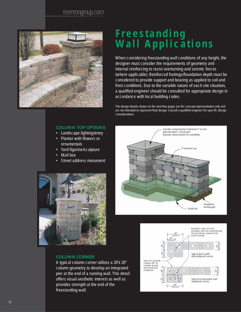
F r e e s t a n d i n g Wa l l A p p l i c a t i o n sWhen considering freestanding wall conditions of any height, thedesigner must consider the requirements of geometry andinternal reinforcing to resist overturning and seismic forces(where applicable). Reinforced footings/foundation depth must beconsidered to provide support and bearing as applied to soil andfrost conditions. Due to the variable nature of each site situation,a qualified engineer should be consulted for appropriate design inaccordance with local building codes.
The design details shown on the next few pages are for concept representation only andare not intended to represent final design. Consult a qualified engineer for specific designconsiderations.
COLUMN CORNER
A typical column corner utilizes a 20"x 20"column geometry to develop an integratedpier at the end of a running wall. This detailoffers visual aesthetic interest as well asprovides strength at the end of thefreestanding wall.
COLUMN TOP OPTIONS
• Landscape lighting/entry• Planter with flowers or
ornamentals• Yard figurine/sculpture• Mail box • Street address monument
Consider using Keystone KapStones™ to com-plete the pillars. consult your keystone representative for availability.
3" universal cap
Grade line
Foundation leveling pad
units at column
turned 90° to
course below
for interlock
strength
possible core out for
internal vertical reinforcing
or electrical conduit for
light fixture.
20"(500 mm)
10"
(250
mm
)
20"(500 mm)
10"(250 mm)
10"
(250
mm
)
10"
(250
mm
)10
"(2
50 m
m)
10"
(250
mm
)
10"
(250
mm
)
Typical base and/or odd numbered courses
Typical second and/or even numbered courses

we make it easy
13
Wa l l E n d C o l u m nThe wall end column is a larger version of the “ColumnCorner” detail. The benefit of this design option is thedevelopment of internal reinforcement to provide for greaterstrength and height, along with a larger footprint dimensionfor aesthetic purposes. Additionally, for markets where the10"/8" unit is available, this can be combined with the 12"/10"unit to create a 20" long segment of the 30" x 30" column.
Internal column reinforcing should provide for steel re-bar andsolid concrete grouting in connection with a reinforced con-crete foundation.
3" universal cap
Optional cappingpattern
grade line
foundation - leveling pad
Cut caps to fit againstperpendicular surface
30" x 30" end column allows
for a reinforced pier to support
gates, light poles, etc.
30"(750 mm)
30"
(750
mm
)
10"
(250
mm
)
10"(250 mm)
30"(750 mm)
10"(250 mm)
30"
(750
mm
)
30"(750 mm)
10"(250 mm)
10"
(250
mm
)
10"
(250
mm
)
10"
(250
mm
)
10"
(250
mm
)
10"
(250
mm
)
F r e e s t a n d i n gB o r d e r Wa l lWith Keystone Stonegate Country Manor, you have theadded option of building unreinforced freestanding wallsto various plan geometry and limited heights. From lowborder walls, which define the edge of patios and decks tofreestanding entry monuments, pilasters and parapetswalls, Keystone Stonegate Country Manor uses thisinterlocking geometry to achieve wider wall areas whichprovide strength and resistance to overturning forces.
10"
12"
2'-0"(0.6m)max.
3" cap
Base Leveling
Pad
(75mm)
(150mm)
(250mm)
(300mm)
6" (150mm)
6"min.
Typical base and/or odd numbered courses
Typical second and/or even numbered courses

tremrongroup.com
14
Wa l l O f f s e t• Wider wall geometry (footprint) provides greater
strength for parapet walls to resist overturning.• Offsets allow for graceful changes in wall
direction.• Offsets are an opportunity for aesthetic
geometry and landscape feature areas.
" L " R e t u r n E n dSimilar to column corners, this detail offers stabilityand strength to resist overturning forces at the endof a freestanding wall.
Foundation leveling pad
Grade line
3"2'
-0" m
ax.
6"(6
00m
m)
(150m
m)
MIN
.
Notes
• The minimum offset for two parallel walls, as shown in the detailson this page, is 10". Continuous offsets @ maximum 10'-0" O.C. willprovide strength at parapet walls in coordination with constructionadhesive (Keystone Kapseal) and/or vertical reinforcement asrequired by engineer.
• It is important to use overlapping unit combinations at the offsetlocation where two units combined together equal 20" in length (see plan geometry on the right).
• Details showing freestanding wall applications show partialsections of walls. The unfinished ends, with channel openingsvisible, are not meant to portray a finished condition.
10"
10"
10"
(250
mm
)(2
50m
m)
(250mm)
10"
wall offset condition
is strengthened when
units are overlapped
versus stacked.
10"
10"(250mm)
(250
mm
)(2
50m
m)
Grade line
Foundation leveling pad
3" universal cap shown Options: cut stone, precast concrete or othermasonry materials
10"(250 mm)
20"
(500
mm
)20
"(5
00 m
m)
10"(250 mm)
20"
(500
mm
)
BASE
COURSE
Typical base and/or odd numbered courses
Typical second and/or even numbered courses

we make it easy
15
P i l a s t e r D e t a i lThe pilaster detail creates a deeper wall sectionwithin the wall which can provide stability for aretaining structure, freestanding wall or parapet.
L1
H1
H
grade
grade
grade
leveling pad
geogrid soil
reinforcement
L1 < H1 x 2
Te r r a c e sTerraces are a pleasing way to build a taller retaining wall whereaesthetics dictate the separation of walls to reduce the wall heightand large mass appearance. Closely spaced terraces need to bereviewed by a qualified engineer to avoid global instability issuesand to make sure soil reinforcement (geogrids) are properlydesigned to handle the loads for the entire wall structure.
Terraced walls should be analyzed as a complete wall systemversus individual walls unless they are spread apart greater thantwice the wall height of each terrace and the soils are freedraining and granular in nature.
3" universal cap
Split universal cap as necessary to create 90° end cap condition. Overhang unit by 1" to match overhang along unit sides.
Typical base course
Typical second and/or even course(s)
TERRACE WALL PROXIMITY
EVALUATION
For walls where L1 is less than or equal to H1 x 2, then the walls are to beconsidered as a composite and the entire wall height (H) needs to beconsidered in the design.
L1
H1
grade
leveling pad
geogrid soil
reinforcement
grade
grade
L1 < H1 x 2
For walls where L1 is greater than or equal to H1 x 2, then the walls typically are analyzed separately.Walls built on slopes greater than or equal to 3:1 or on soft soils need to be analyzed for "global stability".Consult a qualified engineer.

tremrongroup.com
16
D e s i g n C o n s i d e r a t i o n s10" 12"
no surcharge/
level grade
height
varies
3" cap
backfill
drainage
material
base leveling pad
(250mm) (300mm)
(75mm)
6" (150mm)
Design Assumptions
• Friction angle (PHI) for earth pressure calculations of geogrid reinforcedwalls is evaluated at 26°, 30° and 34° only. For other soil type analysis, referto KeyWall Software program or consult with a qualified engineer.
• Moist weight of three soil types indicated is 120 lb./ft.3 (19kN/m2).• Sliding calculations use 6" (150mm) crushed stone leveling pad as
compacted foundation material.• All backfill materials are compacted to 95% Standard Proctor density.• The term "vertical" is a wall built to a near vertical alignment having a slight
positive setback (1° ±).• The information provided herein is for preliminary design use only. A
qualified engineer should be consulted for design and analysis of structures.Keystone Retaining Wall Systems, Inc. assumes no liability for the improperuse of this information.
GRAVITY WALL
Near Vertical Detail
10" 12"
no surcharge/
level grade
height
varies
3" cap
backfill
drainage
material
base leveling pad
(250mm) (300mm)
(75mm)
9.5
+/-
6" (150mm)
GRAVITY WALL
Setback Detail 9.5° ± Batter
MAXIMUMHEIGHT
NEAR VERTICAL
Sand / gravelphi= 34°
Silty sandphi = 30°
Silt / lean clayphi = 26°
level
2'-0"(0.6m)
1'-6"(0.45m)
1'-6"(0.45m)
1'-6"(0.45m)
1'-6"(0.45m)
1'-0"(0.3m)
3'-0"(0.9m)
2'-6"(0.75m)
2'-0"(0.6m)
1'-6"(0.45m)
2'-0"(0.6m)
2'-6"(0.75m)
level3h:1v 3h:1v
9.5° ± BATTER
GRAVITY WALLS (maximum unreinforced wall height) Design Notes
For low (non-structural) landscape retain-ing walls, Keystone Stonegate CountryManor can be constructed as a non-rein-forced gravity wall as shown in the chart tothe left. This chart is for retaining walls inthe "near vertical" option. Note: use pinsand construction adhesive at lowborder/parapet walls.
reinforced fill
parapet
(max. 1'-0" [300mm])
height
varies
drainage material
(crushed stone 1/2" - 3/4")
base leveling pad
geogrid
reinforcement
3" cap
10" 12"
12"
note: wall geometry with
90° corners or serpentine
curves is necessary for
stability and resistance
to overturn of parapet.
(250mm)
(300mm)
(75mm)
(300mm)
(10 - 20 mm)
6" (150mm)
embedment depth below grade minimum
1 unit or H/20
REINFORCED WALL
Near Vertical Detail
reinforced fill
drainage material
(crushed stone 1/2" - 3/4")
base leveling pad
geogrid
reinforcement
3" cap
10" 12"
12"
embedment depth below grade minimum
1 unit or H/20
(250mm)
(300mm)
(75mm)
(150mm)
(300mm)
(10 - 20 mm)
9.5+/-
height
Varies
6"
REINFORCED WALL
Setback Detail 9.5° ± Batter

we make it easy
17
D e s i g n C h a r t sThe following charts assume the use of a coated polyester geogrid with a minimumallowable design strength of: LTDS = 750 plf (10.9 kN/m) or Tal = 500 plf (7.3 kN/m) Silt/Lean Clay: f=26°, g=120 pcf (19kN/m3)
H
No Surcharge
ReinforcedSoil Zone
4.0'
4.0'
4.0'
4.0'
4.0'
4.0'
6.0'
5.0'5.0'
5.0'
5.0'
5.0'
5.0'
5.0'
5.0'
4.0'
4.0'
4.0'
5.0'
6.0'6.0'
7.0'
5.0'
2.25' (0.7m) 3.25' (1.0m) 4.25' (1.3m) 5.25' (1.6m) 6.25' (1.9m) 7.25' (2.2m) 8.25' (2.5m)
H
100 psf Surcharge
ReinforcedSoil Zone
4.0'
4.0'
4.0'
5.0'5.0'
5.0'
5.0'
6.0'
7.0'
5.0'
5.0'
5.0'5.0'
5.0'
6.0'
6.0'
6.0'
6.0'
7.0'
6.0'
6.0'
6.0'
6.0'
7.0'
8.0'
2.25' (0.7m) 3.25' (1.0m) 4.25' (1.3m) 5.25' (1.6m) 6.25' (1.9m) 7.25' (2.2m) 8.25' (2.5m)
H
31
ReinforcedSoil Zone 4.0'
4.0'
4.0'
4.0'
4.0'
7.0'
7.0'
5.0'
5.0'
5.0'
5.0'
5.0'
4.0'
4.0'
4.0'
4.0'
7.0'
7.0'
8.0'
8.0'
8.0'
8.0'
8.0'
7.0'7.0'
8.0'8.0'
2.25' (0.7m) 3.25' (1.0m) 4.25' (1.3m) 5.25' (1.6m) 6.25' (1.9m) 7.25' (2.2m) 8.25' (2.5m)
ReinforcedSoil Zone
H
No Surcharge
4.0'
4.0'
4.0'
4.0'
4.0'
4.0'
4.0'
4.0'
5.0'
5.0'
5.0'
5.0'
5.0'
5.0'
5.0'
4.0'
6.0'
4.0'
5.0'
5.0'
5.0'
5.0'
2.25' (0.7m) 3.25' (1.0m) 4.25' (1.3m) 5.25' (1.6m) 6.25' (1.9m) 7.25' (2.2m) 8.25' (2.5m)
ReinforcedSoil Zone
H
100 psf Surcharge
4.0'
5.0'
4.0'
4.0'
4.0' 5.0'5.0'
5.0'
5.0'
5.0'
6.0'
5.0'
5.0'
5.0'
4.0'
5.0'
4.0'
4.0'6.0'
6.0'
6.0'
6.0'
6.0'
7.0'
2.25' (0.7m) 3.25' (1.0m) 4.25' (1.3m) 5.25' (1.6m) 6.25' (1.9m) 7.25' (2.2m) 8.25' (2.5m)
H
31
ReinforcedSoil Zone
5.0'
4.0'
4.0'
4.0'
4.0'
4.0'
5.0'
5.0'
5.0'
5.0'
6.0'
6.0'
6.0'
6.0'
6.0'
6.0'
4.0'
4.0' 5.0'
5.0'
5.0'
5.0'
2.25' (0.7m) 3.25' (1.0m) 4.25' (1.3m) 5.25' (1.6m) 6.25' (1.9m) 7.25' (2.2m) 8.25' (2.5m)
Reinforced walls - (near vertical)
Reinforced walls - (near vertical)
Reinforced walls - (near vertical)
Reinforced walls - (9.5° + setback)
Reinforced walls - (9.5° + setback)
Reinforced walls - (9.5° + setback) Case 3
Case 2
Case 1
Case 3
Case 2
Case 1
H=
H=
H=
H=
H=
The information provided herein is for preliminary design use only. A qualified engineer should be consulted for design andanalysis of structures. Keystone Retaining Wall Systems, Inc. assumes no liability for the improper use of this information.*Information on specific geogrids is available from the geogrid manufacturer.
H=

tremrongroup.com
18
D e s i g n C h a r t sThe following charts assume the use of a coated polyester geogrid with a minimum
allowable design strength of: LTDS = 750 plf (10.9 kN/m) or Tal = 500 plf (7.3 kN/m)Silty Sand: f=30°, g=120 pcf (19kN/m3)
H
No Surcharge
ReinforcedSoil Zone
3.0'
2.25' (0.7m)
3.0'
3.0'
4.0'
4.0'
4.0'
4.0'
4.0'
5.0'
4.0'
4.0'
4.0'
6.0'
5.0'
5.0'
5.0'
5.0'
3.25' (1.0m) 4.25' (1.3m) 5.25' (1.6m) 6.25' (1.9m) 7.25' (2.2m) 8.25' (2.5m)
5.0'
5.0'
5.0'
5.0'
5.0'
6.0'
H
100 psf Surcharge
ReinforcedSoil Zone
4.0'
4.0'
4.0'
4.0'
4.0'
4.0'
4.0'
5.0'4.0'
4.0'
4.0'
6.0'
6.0'
5.0'
5.0'
5.0'
5.0'
7.0'
5.0'
5.0'
5.0'
5.0'
5.0'
2.25' (0.7m) 3.25' (1.0m) 4.25' (1.3m) 5.25' (1.6m) 6.25' (1.9m) 7.25' (2.2m) 8.25' (2.5m)
H
31
ReinforcedSoil Zone
3.0'
4.0'
4.0'
4.0'
4.0'
4.0'
4.0'
4.0'
4.0'
4.0'
4.0'
5.0'
6.0'
5.0'
5.0'
5.0'
5.0'
6.0'
5.0'
5.0'
5.0'
5.0'
5.0'
2.25' (0.7m) 3.25' (1.0m) 4.25' (1.3m) 5.25' (1.6m) 6.25' (1.9m) 7.25' (2.2m) 8.25' (2.5m)
ReinforcedSoil Zone
H
No Surcharge
3.0'
3.0'
4.0'
4.0'
4.0'
4.0'
4.0'
4.0'
4.0'
4.0'
4.0'
5.0'
5.0'
5.0'
5.0'
5.0'
5.0'
5.0'
5.0'
5.0'
5.0'
5.0'
2.25' (0.7m) 3.25' (1.0m) 4.25' (1.3m) 5.25' (1.6m) 6.25' (1.9m) 7.25' (2.2m) 8.25' (2.5m)
ReinforcedSoil Zone
H
100 psf Surcharge
3.0'
4.0'
5.0'
4.0'
4.0'
4.0'
4.0'
4.0'
4.0'
4.0'
4.0'
4.0' 5.0'
5.0'
5.0'
5.0'
5.0'
5.0'
5.0'
5.0'
5.0'
5.0'
5.0'
2.25' (0.7m) 3.25' (1.0m) 4.25' (1.3m) 5.25' (1.6m) 6.25' (1.9m) 7.25' (2.2m) 8.25' (2.5m)
H
31
ReinforcedSoil Zone
3.0'5.0'
4.0'
3.0'
3.0'
4.0'
4.0'
4.0'
4.0'
4.0'
4.0'
4.0'
4.0'
5.0'
5.0'
5.0'
5.0'
5.0'
5.0'
5.0'
5.0'
5.0'
5.0'
2.25' (0.7m) 3.25' (1.0m) 4.25' (1.3m) 5.25' (1.6m) 6.25' (1.9m) 7.25' (2.2m) 8.25' (2.5m)
Reinforced walls - (near vertical)
Reinforced walls - (near vertical)
Reinforced walls - (near vertical)
Reinforced walls - (9.5° + setback)
Reinforced walls - (9.5° + setback)
Reinforced walls - (9.5° + setback) Case 3
Case 2
Case 1
Case 3
Case 2
Case 1
H=
H=
H=
H=
H=
The information provided herein is for preliminary design use only. A qualified engineer should be consulted for design andanalysis of structures. Keystone Retaining Wall Systems, Inc. assumes no liability for the improper use of this information.
*Information on specific geogrids is available from the geogrid manufacturer.
H=

we make it easy
19
D e s i g n C h a r t sThe following charts assume the use of a coated polyester geogrid with a minimumallowable design strength of: LTDS = 750 plf (10.9 kN/m) or Tal = 500 plf (7.3 kN/m) Sand/Gravel: f=34°, g=120 pcf (19kN/m3)
H
No Surcharge
ReinforcedSoil Zone
3.0'
3.0'
4.0'
4.0'
4.0'
4.0'
4.0'
4.0'
4.0'
4.0'
4.0'
5.0'
5.0'
5.0'
5.0'
5.0'
5.0'
5.0'
5.0'
5.0'
2.25' (0.7m) 3.25' (1.0m) 4.25' (1.3m) 5.25' (1.6m) 6.25' (1.9m) 7.25' (2.2m) 8.25' (2.5m)
H
100 psf Surcharge
ReinforcedSoil Zone
3.0'
4.0'
4.0'
4.0'
4.0'
4.0'
5.0'5.0'
5.0'
5.0'
5.0'
2.25' (0.7m) 3.25' (1.0m) 4.25' (1.3m) 5.25' (1.6m) 6.25' (1.9m) 7.25' (2.2m) 8.25' (2.5m)
4.0'
4.0'
4.0'
4.0'
4.0'
5.0'
5.0'
5.0'
5.0'
5.0'
H
31
ReinforcedSoil Zone
3.0'
3.0'
3.0'
4.0'
4.0'
4.0'
4.0'
4.0'
5.0'
5.0'
5.0'
5.0'
5.0'
5.0'
2.25' (0.7m) 3.25' (1.0m) 4.25' (1.3m) 5.25' (1.6m) 6.25' (1.9m) 7.25' (2.2m) 8.25' (2.5m)
4.0'
4.0'
4.0'
4.0'
5.0'
5.0'
5.0'
5.0'
5.0'
ReinforcedSoil Zone
H
No Surcharge
3.0'
3.0'
4.0'
4.0'
4.0'
4.0'
4.0'
4.0'
4.0'
4.0'
4.0'
5.0'
5.0'
5.0'
5.0'
5.0'
5.0'
5.0'
5.0'
5.0'
2.25' (0.7m) 3.25' (1.0m) 4.25' (1.3m) 5.25' (1.6m) 6.25' (1.9m) 7.25' (2.2m) 8.25' (2.5m)
ReinforcedSoil Zone
H
100 psf Surcharge
3.0'
4.0'
4.0'
4.0'
4.0'
4.0'
4.0'
4.0'
4.0'
4.0'
4.0'
5.0'
5.0'
5.0'
5.0'
5.0'
5.0'
5.0'
5.0'
5.0'
2.25' (0.7m) 3.25' (1.0m) 4.25' (1.3m) 5.25' (1.6m) 6.25' (1.9m) 7.25' (2.2m) 8.25' (2.5m)
4.0'
H
31
ReinforcedSoil Zone 4.0'
4.0'
4.0'
4.0'
4.0'
4.0'
4.0'
4.0'
4.0'
4.0'
4.0'
5.0'
5.0'
5.0'
5.0'
5.0'
5.0'
5.0'
5.0'
5.0'
2.25' (0.7m) 3.25' (1.0m) 4.25' (1.3m) 5.25' (1.6m) 6.25' (1.9m) 7.25' (2.2m) 8.25' (2.5m)
Reinforced walls - (near vertical)
Reinforced walls - (near vertical)
Reinforced walls - (near vertical)
Reinforced walls - (9.5° + setback)
Reinforced walls - (9.5° + setback)
Reinforced walls - (9.5° + setback) Case 3
Case 2
Case 1
Case 3
Case 2
Case 1
H=
H=
H=
H=
H=
The information provided herein is for preliminary design use only. A qualified engineer should be consulted for design andanalysis of structures. Keystone Retaining Wall Systems, Inc. assumes no liability for the improper use of this information.*Information on specific geogrids is available from the geogrid manufacturer.
H=

Top, Right:, and Inset: Keystone Stonegate Country Manor 20

21
tremrongroup.com
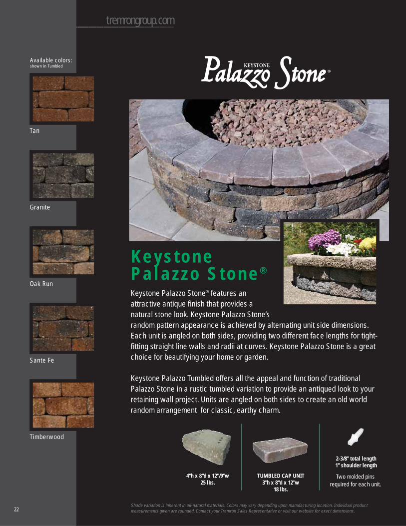
Shade variation is inherent in all-natural materials. Colors may vary depending upon manufacturing location. Individual productmeasurements given are rounded. Contact your Tremron Sales Representative or visit our website for exact dimensions.
TUMBLED CAP UNIT3"h x 8"d x 12"w
18 lbs.
4"h x 8"d x 12"/9"w25 lbs.
2-3/8" total length1" shoulder length
Available colors:shown in Tumbled
Tan
Granite
Oak Run
Sante Fe
Timberwood
Two molded pins required for each unit.
K e y s t o n eP a l a z z o S t o n e ®
Keystone Palazzo Stone® features anattractive antique finish that provides anatural stone look. Keystone Palazzo Stone’srandom pattern appearance is achieved by alternating unit side dimensions.Each unit is angled on both sides, providing two different face lengths for tight-fitting straight line walls and radii at curves. Keystone Palazzo Stone is a greatchoice for beautifying your home or garden.
Keystone Palazzo Tumbled offers all the appeal and function of traditionalPalazzo Stone in a rustic tumbled variation to provide an antiqued look to yourretaining wall project. Units are angled on both sides to create an old worldrandom arrangement for classic, earthy charm.
22

O u r L o c a t i o n s
23
2885 St. Clair StreetJacksonville, FL 32254866.358.5900 or904.359.5900Fax 904.359.5901
3144 N.E. Hwy. 17Arcadia, FL 34266877.490.0990 or863.491.0990Fax 863.491.8990
11321 N.W. 138th StreetMiami, FL 33178800.567.1480 or305.825.9000Fax 305.823.6614
JACKSONVILLE
ARCADIA
MIAMI

11321 N.W. 138th StreetMiami, FL 33178800.567.1480 or305.825.9000Fax 305.823.6614
2885 St. Clair StreetJacksonville, FL 32254866.358.5900 or904.359.5900Fax 904.359.5901
3144 N.E. Hwy. 17Arcadia, FL 34266877.490.0990 or863.491.0990Fax 863.491.8990
MIAMI
JACKSONVILLE
ARCADIA
tremrongroup.com
Cover Photo: Keystone Stonegate Country Manor
www.keystonewalls.com