travel trailer fifth wheel owners manual table of contents introduction ..... .....a
TRANSCRIPT

1
TRAVEL TRAILERFIFTH WHEEL
OWNERS MANUAL
This Quality Recreational Vehicle Built By:

2
SKYLINE CUSTOMER SATISFACTION
Skyline Customer Satisfaction is more than just a promise — We
believe you deserve quality in every aspect of ownership. To ensure
your continued satisfaction we’re dedicated to providing you with
a quality product along with the very best service available in our
industry. Skyline’s “C ommitment of Excellence” will be a source of
pride and satisfaction for you.
Commitment of ExcellenceOWNER
SATISFIED CUSTOMER
ORIGINAL DEL. DATE DEALER NO.
11-15-93 045454
VEHICLE ID NO. MODEL NO.
7653-0398J 2955
SAMPLE
WARRANTY
CARD
3
TABLE OF CONTENTS
Introduction .........................................................................................................................A
Warranty ..............................................................................................................................B
Skyline Cares About You ....................................................................................................C
Your Travel Trailer — A True Recreational Vehicle ............................................................1
Do’s and Don’ts for Equipment Selection and
Preparation for Towing .....................................................................................................1
Trailer Loading ....................................................................................................................2
Hitching Up ..........................................................................................................................7
Hitching Procedures for Conventional Trailers ...................................................................7
Hitching Procedures for Fifth Wheel Trailers ......................................................................9
Tires .....................................................................................................................................9
Changing Tires ...................................................................................................................11
The Braking System ...........................................................................................................12
Trailer Driving Techniques ................................................................................................15
Stabilization .......................................................................................................................17
Utility Systems ...................................................................................................................19
Utility Diagrams .................................................................................................................25
Ventilation and Condensation ............................................................................................31
The Exterior of Your Travel Trailer ...................................................................................35
The Interior of Your Travel Trailer ....................................................................................39
Fire and Emergency Procedures ........................................................................................53
Emergency Exits .............................................................................................................53
Reporting Safety Defects ...................................................................................................55
Travel Trailer and Fifth Wheel Slide-Out Room
Adjustment and Operation .............................................................................................57
Slide-Out Rooms — Hydraulic ..........................................................................................60
Winterize Checklist for Travel Trailer ...............................................................................61
Travel Checklist .................................................................................................................66
Camping Checklist .............................................................................................................67
Recommended Maintenance Schedule ..............................................................................68
Warranty Information .........................................................................................................69
Skyline Recreational Vehicle Division Directory ..............................................................70
Index ..................................................................................................................................71

4

5
INTRODUCTION
We’re delighted that you chose to invest in a Skyline-built trailer. Your
new travel trailer is designed and constructed to make each trip as safe
and carefree as possible, and we won’t be satisfi ed until you’re completely
happy with it.
Before your fi rst trip, please take the time to read this manual and the ap-
pliance and other manuals that come with it. They will help you to get the
most enjoyment out of your purchase.
All manuals should be kept available for easy reference.
NOTE: Some equipment and features described or shown in this manual
may be optional on some Skyline models. The term “travel trailer” as used
in this manual includes fi fth wheel travel trailers unless otherwise indi-
cated.

6
HOW TO OBTAIN SERVICE
Your continued satisfaction with your travel trailer is of utmost importance to Skyline. Please fol-
low these steps for fast, effi cient warranty service.
1. Inspect your travel trailer thoroughly to determine exactly what service is required.
2. Make a list of the required service. Be sure to sign it.
3. Call, write or visit your dealer.
If your request is not resolved to your satisfaction, make sure it is brought to the attention of
the owner or general manager of the dealership. They will obtain factory assistance, if needed.
NOTE: Your appliances are warranted both by the appliance manufacturer and by Skyline.
All appliances furnished with your travel trailer are “name-brands”, and the manufacturer
may have a service facility near you. If so, you may be able to obtain even faster service by
requesting service directly from the appliance manufacturer.
4. Factory: If your request has not been resolved to your satisfaction within a reasonable time,
write (include the complete serial number of your travel trailer and your telephone number
with a copy of your list of required service) and/or call the factory service representative
below, or E-Mail us at, [email protected].
5. In those rare cases in which your dealer and the factory service representative have been un-
able to resolve the problem, write the Director of Consumer Relations, Skyline Corporation,
P.O. Box 743, Elkhart, Indiana 46515-0743, or at [email protected]. Include the
complete serial number of your travel trailer, your telephone number and a complete list of the
required manufacturer’s warranty service. Your request will receive prompt attention.
All service under your Skyline warranty will be performed without charge for either parts or
labor. Whether service is performed by the dealer, the factory or others, Skyline accepts fi nal
responsibility for fulfi llment of all its warranty obligations. Skyline will use its best efforts to
see that all manufacturer’s warranty service is completed as expeditiously as possible.
Warranty service requests must be made within the warranty period and should ordinarily go to
your dealer.
FULL ONE-YEAR WARRANTY
Manufacturing defects reported to Skyline within one year after original retail delivery of your new Travel Trailer by an authorized dealer will be corrected without charge and within reasonable times. Excluded are misuse (including lack of reasonable maintenance), minor imperfections, alterations, and dealer or owner improper transportation, installation or hookup.
This warranty gives you specifi c legal rights. You may have other rights which vary from state to state.

7
SKYLINE CARES ABOUT YOU
Skyline is a leader in the recreational vehicle industry because Skyline cares about its
RV owners. Your investment in your Skyline-built travel trailer is protected by Skyline’s
extensive six-point program:
1. Product design and engineering. Skyline maintains a complete staff of professional
engineers and designers.
2. Code construction. Every travel trailer built by Skyline meets or exceeds code stan-
dards and features quality components including name brand appliances.
3. Underwriters Laboratories. The UL label on your trailer means that America’s
most respected independent testing agency has reviewed the plans and inspected the
travel trailer during production.
4. Full one-year warranty. It’s the no-nonsense guarantee printed in this manual. We
urge you to read it.
5. Full fi eld service. Skyline and its dealers are pledged to back up the warranty with
prompt, courteous service that takes care of problems quickly and effectively.
6. Financial strength. Skyline is one of America’s soundest companies fi nancially. You
can rely on Skyline today — and tomorrow.
To further ensure your satisfaction:
1. Your travel trailer is inspected by your dealer after it leaves the factory and before it
is delivered to you.
2. Upon taking delivery, have your dealer go over your travel trailer with you and
instruct you concerning the appliances and other working parts. Be sure to ask your
dealer to demonstrate the operation of any appliance or item of equipment which you
do not understand.
3. As with your other vehicles, your travel trailer will require regular care and main-
tenance. This manual, together with the information provided by manufacturers of
various components, provides a maintenance schedule that you can and should fol-
low to ensure safe, trouble-free service from your trailer. Studying these instructions
carefully and maintaining a good working knowledge of your trailer and how to care
for it will help you enjoy it for many miles and many years.
If you should have a problem that is not resolved to your satisfaction by your local dealer,
call or write the service manager at the factory nearest you. A list of factories can be
found in this manual.
All of us at Skyline join with your dealer in wishing you every happiness in your new
travel trailer.

8
YOUR TRAVEL TRAILER — A TRUE RECREATIONAL VEHICLE
Your travel trailer is a vacation home on wheels. It is carefully designed for every normal recreational use and activity including travel. It is not designed or intended to be used as long-term or permanent, full-time housing. Long-term or full-time occupancy may lead to premature deterioration and may, under the terms of the warranty, constitute misuse and reduce your warranty protection.
Please refer to page 31 of this manual and review the section relating to ventilation and condensation problems that may occur due to long-term occupancy.
WARNING: Never ride in your recreational vehicle.
Skyline strongly recommends that your recreational vehicle not be occupied while travel-ing. It is unsafe and illegal to ride in a travel trailer in all states and it is illegal to ride in a fi fth wheel in most states. Your recreational vehicle is not equipped with seat belts or other highway safety provisions commonly required for passenger vehicles. Also in some emergency conditions cargo could shift suddenly resulting in injury or even death.
DO’S AND DON’TS FOR EQUIPMENT SELECTION AND PREPARATION FOR TOWING
• Be sure the tow vehicle is large enough for your trailer or fi fth wheel and has the needed power and heavy duty running gear. It must be rated by its manufacturer to tow the gross weight, and to carry the hitch weight of the fully loaded trailer or fi fth wheel.
NOTE: Heavy duty commercial vehicles larger than one ton may be used only if an energy absorbing hitch, such as the Air Ride Hitch™, is used to couple the recreational vehicle to the tow vehicle. The rough ride of the larger trucks can cause structural prob-lems to develop in recreational vehicles if an energy absorbing hitch is not utilized.
• Use a weight distributing hitch rated not less than the trailer Gross Vehicle Weight Rating (GVWR). Follow the tow vehicle and hitch manufacturers' instructions. Install the hitch ball as close as practical to the rear bumper to minimize rear overhang. (Does not apply to fi fth wheels.)
• Do not overtighten the weight distributing hitch spring bars. Follow the instructions of the hitch manufacturer. When in doubt, use the less tight spring bar setting. (Does not ap-ply to fi fth wheels.)
• Use a sway control system. Install and adjust according to the instructions of the sway control manufacturer. (Does not apply to fi fth wheels.)
• Use a brake controller that automatically applies the brakes in proportion to the tow vehicle brakes and also has a hand control for applying the trailer brakes only.
• Adjust the brake controller so that the brakes of the trailer come on as quickly as possible without sliding the tires of the loaded trailer during strong braking.
• Infl ate the rear tires of the tow vehicle to their maximum cold pressure. (See the maxi-mum pressure rating on the rear tire sidewalls.)
• Load heavy objects and goods as close to the trailer axle(s) as possible. Do not place heavy objects on the rear bumper or on the tongue.
Your trailer may be equipped with an optional spare tire mounted on the bumper. The bumper is designed only to carry the spare tire, approximately 65 pounds. If the trailer is not equipped with a spare, no load greater than 65 pounds shall be placed on the bumper.

9
The following label has been affi xed to the bumper:
CAUTION: THE BUMPER IS DESIGNED TO CARRY THE SPARE TIRE ONLY.
DO NOT PLACE ADDITIONAL CARGO ON THE BUMPER.
• If possible, totally fi ll or empty the water tank to minimize “sloshing,” which may
affect towing stability.
• If possible, empty holding tanks to minimize “sloshing,” which may affect towing
stability.
• Be careful to load the trailer to comply with the specifi ed maximum and minimum
tongue weight percentages. Weigh the fully loaded trailer from time to time to verify
tongue weight.
• Adjust the hitch ball height so that the fully loaded trailer is level front-to-rear when
attached to the fully loaded tow vehicle with hitch spring bars tightened. Do not
permit the front to be lower than the rear on trailers with tandem axles. (Fifth wheel
trailers are less sensitive to altitude, but should be towed near level to achieve best
stability and avoid the possibility of overloading one of the trailer axles.)
• Do not exceed the trailer Gross Axle Weight Rating(s) (GAWR), or Gross Vehicle
Weight Rating (GVWR). The fully loaded trailer should be weighed from time to
time to verify that trailer GAWR(s) and GVWR are not exceeded, and that the loads
on the right and left wheels are approximately equal. When weighing to determine
axle loading, the trailer must be fully loaded and hitched to the fully loaded tow
vehicle, with spring bars tightened. (Spring bars do not apply to fi fth wheels.)
• Do not exceed the tow vehicle Gross Axle Weight Rating(s) (GAWR) or Gross
Vehicle Weight Rating (GVWR). Weigh the tow vehicle from time to time to verify
these loadings. When weighing, the tow vehicle must be fully loaded with goods,
passengers, and driver, and must be hitched to the fully loaded trailer, with spring
bars tightened. (Spring bars do not apply to fi fth wheels.)
TRAILER LOADING
Proper trailer positioning and loading are important not only for ease of hauling, but for safety. The correct loaded weight on the hitch is a minimum of eight percent of trailer weight. Fifth wheel trailers should carry higher hitch loads (15 to 25 percent). If insuf-fi cient weight is placed on the hitch, the trailer will tend to move from side to side, or to “fi shtail”, which can be dangerous. Towed trailers are designed to have proper weight on the hitch for balance when the trailer fl oor is level.
All objects should be held securely in place. Loose items can cause interior damage and erratic trailer movements. They can even be a hazard to others if they fall out. Load shifts can affect driving and handling enough to cause serious, unexpected danger. Inspect tie-downs and fastenings, as well as the load at regular intervals every hour or two, depend-ing on roads, curves, hills, and speed. The fi rst check should be made within a half hour after the trip is started or after the fi rst 25 miles, since some initial settling is likely.
10
If you are going on a long trip, take a “shakedown cruise” of a few miles the weekend
before you leave. This will test your load, safety equipment, hitch, and might reveal
things you missed or forgot. By getting everything in order before you leave home, you
can prevent delays and annoyances that could take the fun out of your trip.
Many owners place luggage, camping equipment, bicycles, and other items in the travel
trailer. The weight of everything put on or in a trailer, whether temporarily or permanent-
ly built-in, must be included in fi guring the total load.
CAUTION: OVERLOADING OR IMBALANCED LOADING OF YOUR TRAV-
EL TRAILER CAN AFFECT HANDLING OR CAUSE AN ACCIDENT THAT
COULD RESULT IN SERIOUS INJURY OR DEATH.
Follow procedures on the “Caution” label located on your kitchen overhead door to deter-
mine actual weight of the loaded trailer.
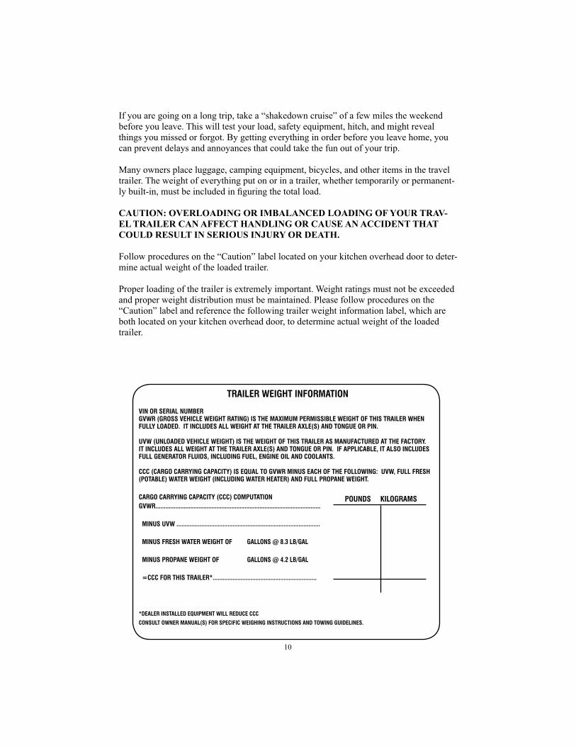
Proper loading of the trailer is extremely important. Weight ratings must not be exceeded
and proper weight distribution must be maintained. Please follow procedures on the
“Caution” label and reference the following trailer weight information label, which are
both located on your kitchen overhead door, to determine actual weight of the loaded
trailer.
TRAILER WEIGHT INFORMATION
VIN OR SERIAL NUMBERGVWR (GROSS VEHICLE WEIGHT RATING) IS THE MAXIMUM PERMISSIBLE WEIGHT OF THIS TRAILER WHEN FULLY LOADED. IT INCLUDES ALL WEIGHT AT THE TRAILER AXLE(S) AND TONGUE OR PIN.
UVW (UNLOADED VEHICLE WEIGHT) IS THE WEIGHT OF THIS TRAILER AS MANUFACTURED AT THE FACTORY. IT INCLUDES ALL WEIGHT AT THE TRAILER AXLE(S) AND TONGUE OR PIN. IF APPLICABLE, IT ALSO INCLUDES FULL GENERATOR FLUIDS, INCLUDING FUEL, ENGINE OIL AND COOLANTS.
CCC (CARGO CARRYING CAPACITY) IS EQUAL TO GVWR MINUS EACH OF THE FOLLOWING: UVW, FULL FRESH (POTABLE) WATER WEIGHT (INCLUDING WATER HEATER) AND FULL PROPANE WEIGHT.
CARGO CARRYING CAPACITY (CCC) COMPUTATIONGVWR....................................................................................................
MINUS UVW ....................................................................................... MINUS FRESH WATER WEIGHT OF GALLONS @ 8.3 LB/GAL
MINUS PROPANE WEIGHT OF GALLONS @ 4.2 LB/GAL
=CCC FOR THIS TRAILER*...............................................................
*DEALER INSTALLED EQUIPMENT WILL REDUCE CCC
CONSULT OWNER MANUAL(S) FOR SPECIFIC WEIGHING INSTRUCTIONS AND TOWING GUIDELINES.
POUNDS KILOGRAMS

11
The following defi nitions have been provided for reference:
Gross Axle Weight Rating (GAWR) means the value specifi ed by the vehicle manufactur-er as the load-carrying capacity of a single axle system, as measured at the tire / ground interfaces.
Gross Vehicle Weight Rating (GVWR) means the maximum permissible weight of this trailer when fully loaded. It includes all weight at the trailer axle(s) and tongue or pin. The GVWR is equal to or greater than the sum of the Unloaded Vehicle Weight (UVW) plus the Cargo Carrying Capacity (CCC).
Dry or Unloaded Vehicle Weight (UVW) means the weight of this trailer as built at the factory. It includes all weight at the trailer axle(s) and tongue or pin. If applicable, it includes full generator fuel, engine oil, and coolants. The UVW does not include cargo, fresh water, Propane, or dealer installed accessories.
Cargo Carrying Capacity (CCC) is equal to GVWR minus each of the following: UVW, full fresh (potable) water weight (including water heater), full Propane weight. Cargo Carrying Capacity (CCC) means the maximum permissible weight of personal belong-ings, food, fresh water, Propane, tools, and dealer installed accessories. (CCC is equal or less than GVWR minus UVW.)
The total weight, including liquids, groceries, clothing, etc. must not exceed the Gross Vehicle Weight Rating (GVWR) stated on the label on the left front of your trailer. The total load on the front and rear wheels must not exceed the respective Gross Axle Weight Rating (GAWR) shown on the label.
1. The total trailer weight (dry weight of standard unit plus options added plus water stored plus liquid wastes in holding tanks plus all cargo) must not exceed the GVWR stated on the label of your trailer.
2. The total load of your fully loaded trailer on the tires when connected to the towing vehicle must not exceed the combined total Gross Axle Weight Rating (GAWR). The GAWR is also stated on the tag on the front left side of your trailer.
3. Establish the weight of your fully loaded trailer by weighing at a public scale. Con-tact the police department for the location of the nearest one. Weigh separately:
a. The load on the front jack.
b. The total weight on the wheels and jack when disconnected from the towing vehicle.
c. The weight on the wheels when connected to the towing vehicle.
4. Do not permit tongue weight (“3-a” above) to exceed your hitch manufacturer’s recommendation. It should be eight to 15 percent of the total travel trailer weight.
5. Weight “3-b” must not exceed the GVWR.
6. Weight “3-c” must not exceed the combined total GAWR.
7. Equalize side to side loading. Store heavy objects on or near the fl oor.

12
8. Avoid towing with waste holding tank(s) full or partially full. If unavoidable, drive
slowly until one or both tanks can be dumped.
9. Keep water tank either completely full or empty when towing to avoid the shifting of
weight of a partially fi lled tank.
For Fifth Wheel Travel Trailers
1. Use a fi fth wheel hitch for a two-inch SAEJ 700 king pin; an Atwood (or equivalent)
25,000 pound 2-5/16 inch diameter folding ball plate for units equipped with the
Atwood 25,000 pound GVW gooseneck coupler; and a truck capable of towing the
trailer GVWR.
2. The total of your fully loaded trailer on the tires when connected to the towing
vehicle must not exceed the combined total Gross Axle Weight Rating (GAWR). The
GAWR is stated on the tag on the front left side of your trailer.
3. Establish the weight of your fully loaded trailer by weighing it at a public scale.
Contact the police department for the location of the nearest one. Weigh separately:
a. The load on your truck rear wheels when connected to your trailer.
b. The total weight on the wheels and jacks when disconnected from the towing
vehicle.
c. The weight on the wheels when connected to the towing vehicle.
4. Do not permit the rear axle load (“3-a” above) to exceed your truck manufacturer’s
GAWR for the rear axle or your fi fth wheel manufacturer’s recommendations.
5. Weight “3-b” must not exceed your trailer GVWR.
6. Weight “3-c” must not exceed your trailer combined total GAWR.
7. The weight on the hitch, derived from subtracting the weight on the wheels (3c)
from the total weight of the fi fth wheel (3b), should be between 15 - 25% of the total
weight (3b) for good towing.
See your dealer if you have any questions on these rules and other towing tips.
These procedures should be repeated whenever there is any change in vehicles or loading
to ensure that you do not exceed the ratings.
STORAGE
The storage facilities in your trailer have been designed to remain secure while in motion.
Exterior compartments have key operated locks. Drawers rest in small notches or dents
when closed; to open lift slightly to clear the dent, then pull open. When storing articles:

13
• Always keep tools and equipment stored in areas where they will not shift while
traveling.
• Wherever possible, place heavy articles in storage compartments which are low and near the axles for better weight distribution.
• Pack articles carefully in the storage compartments to minimize shifting. If nec-essary, use straps to prevent movement.
• Be sure liquid containers are capped and cannot tip or spill. Secure all glass containers and dishes before traveling.
• Secure all free standing furniture.
• Exterior storage compartments may not be watertight in all climate conditions. Carry any articles which could be damaged by water inside the trailer.
WARNING: OUTSIDE STORAGE COMPARTMENTS ARE NOT SEALED. They are vented enclosures, and are accessible from inside the trailer. Therefore, DO NOT STORE FLAMMABLE, VOLATILE LIQUIDS, HAZARDOUS CHEMICALS OR EQUIPMENT IN THESE AREAS.
SPECIAL TRANSPORTATION PROVISIONS
If your recreational vehicle has been equipped with an entrance door greater than 36 inches in width and an access ramp for that door, only then can your recreational vehicle be used to store motorized vehicles or equipment.
WARNING: ONLY TRAILERS CONSISTING OF BOTH A DOOR (WIDTH GREATER THAN 36 INCHES) AND AN ACCESS RAMP ARE CAPABLE OF TRANSPORTING OR STORING MOTORIZED VEHICLES OR EQUIPMENT.
DANGER: ANY MOTORIZED VEHICLE OR ANY MOTORIZED EQUIPMENT POWERED WITH FLAMMABLE LIQUID CAN CAUSE FIRE, EXPLOSION, OR ASPHYXIATION IF STORED OR TRANSPORTED WITHIN THE RECRE-ATIONAL VEHICLE.
The following steps should be taken to aid in reducing the risks associated with transport-ing, storing, or cohabitation with motorized equipment and vehicles:
1. Do not allow passengers to ride inside the vehicle storage area while vehicles are present.
2. Doors and windows in walls of separation are to be closed while the vehicles are present.
3. Run fuel out of engine of stored vehicles after shutting off fuel at the tank.
4. Do not store or transport motor fuel inside this vehicle.
5. Ventilate the interior of the trailer to reduce the risk of fi re, explosion, or asphyxiation.

14
6. Do not operate gas appliances, pilot lights, or electrical equipment when motorized vehicles or motorized equipment are inside the vehicle.
FAILURE TO COMPLY COULD RESULT IN AN INCREASED RISK OF FIRE, EXPLOSION OR ASPHYXIATION.
WARNING: IT IS NOT SAFE COHABITING IN THE INTERNAL COMBUSTION ENGINE VEHICLE STORAGE AREA WHILE
VEHICLES ARE PRESENT. FAILURE TO FOLLOW THESE IMPORTANT PRECAUTIONS MAY RESULT IN SERIOUS INJURY OR DEATH.
7. Load and store your motorized vehicles and equipment according to the trailer loading and trailer storage sections in this manual.
WARNING: DO NOT EXCEED THE TRAILER GVWR WHEN LOADING YOUR TRAILER.
8. During transit, secure motorized vehicles and motorized equipment so that items do not move while in transit.
9. Remove carpet from section where fueled vehicles or motorized equipment will be stored.
10. Disconnect 12-volt and 120-volt wiring when transporting motorized equipment by use of the 12-volt cutoff switch and 120-volt circuit breakers.
HITCHING UP
Hitching your trailer to the tow vehicle will become routine with experience. Make it a habit to examine all hitch components before hitching the trailer. If you have a conven-tional ball hitch, check for cracked or bent parts, cracked welds, deformed or stripped bolts. Inspect the spring bars and chains. Be sure the ball is tight and well lubricated. Check the trailer tongue for cracks. Be sure the ball locking device works freely. Inspect the safety chains. If you fi nd a defect in any hitch component, correct it before towing the trailer.
If you have a fi fth wheel trailer, check all truck-mounted hitch components. Check for worn, cracked, or bent parts. Be sure the locking device works properly. Inspect the pin box assembly on the trailer. Check the king pin. If you fi nd any defective components, repair or replace them before towing. Be sure all moving parts of the hitch are well lubri-cated.
HITCHING PROCEDURE FOR CONVENTIONAL TRAILERS
Before attempting to hitch up your trailer, read the instructions provided by the manufac-turer of the hitch. Some Skyline trailers accept a 2 inch ball, while others accept a 2-5/16 inch ball. The following instructions apply in most cases. If the instructions provided with your hitch are different from these instructions, follow those of the hitch manufacturer:
1. Turn the tongue jack crank clockwise. This will raise the tongue and coupler. Raise the tongue suffi ciently to clear the hitch ball on the tow vehicle.
2. Back the tow vehicle until the hitch ball is under the hitch ball socket. If you are working alone, a backing aid mirror may be helpful.

15
3. The coupler latch locking lever on the tongue should be fully open. Lower the tongue jack until the ball is fi rmly seated in the socket. Close the coupler latch and secure it with a locking pin or bolt.
4. Raise the tow vehicle and trailer with the tongue jack high enough to allow room to install the hitch spring bars.
5. Attach the spring bars according to the hitch manufacturer’s instructions.
WARNING: FOLLOW THE INSTRUCTIONS OF THE HITCH MANUFAC-TURER FOR ADJUSTING THE WEIGHT DISTRIBUTING HITCH. OVER-TIGHTENING OF HITCH SPRING BARS WILL REDUCE CORNERING AND STOPPING ABILITY AS WELL AS TOWING STABILITY.
6. After adjusting the spring bars, raise the jack to its highest level. Note that the trailer must be relatively level front to back. Tilt in either direction must be kept to an absolute minimum. Having the front lower than the rear reduces towing stability on tandem axle trailers.
7. Install the sway control system according to the manufacturer’s instructions.
8. Connect all safety chains.
WARNING: NEVER ATTACH SAFETY CHAINS TO THE HITCH BALL OR ANY REMOVABLE PART OF THE HITCH.
Safety chains are extremely important, and should be added to your trailer to protect your investment as well as other people’s lives and property. As a trailer owner, it is your responsibility to be familiar with these devices and their correct use. The hitch on your tow vehicle must be equipped with two chain attachment eyes, on each side of the vehicle’s centerline. Install the chains by threading each one through its attachment eye and hooking it back on itself. Adjust each chain length so that it is as short as possible, but still permits full “jackknife” turns without becoming tight. Both chains should be the same length and crossed under the trailer’s tongue to hold the tongue off the ground if the trailer accidentally becomes uncoupled.
9. Connect the breakaway switch lanyard.
WARNING: DO NOT CONNECT THE BREAKAWAY SWITCH LANYARD TO THE HITCH BALL OR ANY REMOVABLE PART OF THE HITCH.
10. Plug in the 12-volt electrical connector.
11. Check stop lights, turn lights, running lights, and electric brakes before driving off. See ELECTRICAL SYSTEM section in this manual for details of the
electrical system and wiring.
12. Reverse the procedure for unhitching, placing blocks at the front and rear of the trailer tires prior to uncoupling the trailer from the tow vehicle to ensure the trailer does not roll away when the coupling is released.

16
HITCHING PROCEDURE FOR FIFTH WHEEL TRAILERS
1. Raise or lower the front of the trailer so that the king pin height matches that of the
coupler assembly in the truck.
2. Open the coupler locking device so the pin will engage the hitch plate jaws.
3. Drop the truck tailgate.
4. Slowly back the truck keeping the king pin and coupler aligned. Fully engage the
king pin and coupler.
5. Close the locking device. Engage the safety latch.
6. Close the truck tailgate.
7. Raise the fi fth wheel jacks.
8. Plug in the 12-volt connector.
9. Connect the breakaway switch lanyard.
WARNING: DO NOT CONNECT THE BREAKAWAY SWITCH LANYARD
TO ANY REMOVABLE PART OF THE HITCH.
10. Run an operational check of stop lights, turn lights, running lights, and electrical
brakes before driving off. See “ELECTRICAL SYSTEM” section of this manual for
details of the electrical system and wiring.
TIRES
The tires are covered by the tire manufacturer’s warranty. In order to get maximum wear
and trouble-free travel, the following maintenance and care is recommended:
1. Maintain proper tire pressure. Improper infl ation is the most common cause of tire
failure. Keep an accurate tire gauge in your tool kit. Check tires cold. Infl ate to the
maximum pressure shown on the tire sidewalls for the load the tire is carrying. DO
NOT BLEED AIR OUT OF WARM TIRES.
2. WARNING: CHECK TIRE PRESSURES OFTEN. ALWAYS CHECK PRES-
SURE WHEN TIRES ARE COLD. DO NOT EXCEED MAXIMUM RECOM-
MENDED PRESSURE.
3. Infl ate the rear tires of the tow vehicle to the maximum cold infl ation pressure
stamped on the tire sidewalls. This improves the stability of the tow vehicle.
4. Avoid overinfl ating; it causes tire damage, and weakens the cord body by reducing
the ability to absorb road shocks. It may also cause rim damage.

17
Figure 3 NEVER USE BUMPER JACKS
Figure 2 TYPICAL SCISSOR JACK
Figure 1 TYPICAL WHEEL CHOCKS

18
5. Avoid underinfl ating; it causes rapid tread wear and often premature failure.
6. Raise the jack to take some of the weight off the tire.
WARNING: WHEEL LUGS MUST BE PROPERLY TORQUED. Tighten all lug nuts before fi rst movement and at 10, 25, and 50 miles. See item number 12 under CHANGING A TIRE for proper torque specifi cations. CAUTION: UNDERTIGHTENENING OR OVERTIGHTENING MAY CAUSE LOSS OR DAMAGE TO WHEELS, HUBS, OR BRAKING CAPABILITY, WHICH COULD RESULT IN SERIOUS PERSONAL INJURY OR DEATH. Please refer to the instruction and maintenance manual for running gear.
REMEMBER: Overinfl ating of tires, oversized tires, and travel over chuck holes and large objects will cause rims to split or crack, and could create serious hazards on the highway.
Check the certifi cation label at the front of the trailer (hitch-end, roadside) for informa-tion on tire replacement (GVW, etc.). All your trailer tires should be the same type, size, and construction — do not mix bias-belted and radial tires. In selecting tires for your trailer, buy the size, type, and load range found on the trailer's certifi cation label.
CHANGING A TIRE
1. Turn on the tow vehicle’s hazard warning fl ashers.
2. Set up fl ares or warning lights.
3. Chock the opposite tire and unhitch the trailer from the tow vehicle, or reduce ten-sion on equalizer bars, if applicable. (See Figure 1)
4. DO NOT use a bumper jack; it may damage the sidewalls or fl oorboard of the trailer. (See Figure 3)
5. Place scissors-type or hydraulic jack on a block of wood, directly UNDER THE FRAME, close to the tire you intend to change. (See Figure 2)
6. Raise the jack to take some of the weight off the tire.
7. Loosen the lug nuts.
8. Raise the jack until the tire clears the ground.
9. Remove the lug nuts, pull off the old tire, and put the spare on the hub.
10. Replace and tighten the nuts.
11. Lower the jack until the tire just touches the ground.
12. Tighten the lug nuts as specifi ed below. 14" Wheel — 85 ft-lbs. 15" Wheel — 120 ft-lbs. 16" — 6 Lug Wheel — 120 ft-lbs. 16" — 8 Lug Wheel — 130 ft-lbs. 16" — 6 Lug Aluminum Wheel — 180 ft-lbs.
13. Lower and remove the jack.
14. BE SURE TO STOP AT THE NEAREST SERVICE FACILITY AND HAVE THE TORQUE CHECKED.

19
THE BRAKING SYSTEM
The electric brakes on your trailer are operated by 12-volt current from the tow vehicle.
The brakes have been factory-calibrated for smooth, positive response. During the break-
in period, brakes may squeak. This is normal, and will cease after a few miles.
BRAKE SYSTEM COMPONENTS
1. Tow Vehicle Battery. This is the primary power source for the trailer braking sys-
tem. The connection is made at the positive post of the battery, or at the tow vehicle
starter solenoid battery terminal.
2. Brake Controller. The electric trailer brakes are automatically applied by the brake
controller, which is usually mounted within easy reach of the tow vehicle driver.
Some controllers are connected to the tow vehicle’s hydraulic brake system, and are
actuated when tow vehicle brakes are applied. Most experienced drivers prefer to
have the trailer brakes set to engage slightly before those of the tow vehicle.
This is particularly helpful during rainy weather or slippery conditions. If the tow ve-
hicle brakes fi rst, the trailer will have a tendency to push the tow vehicle or possibly
“jackknife.” Lag time can be adjusted by turning the brake controller knob according
to the instructions provided with the controller. The new setting will be retained until
a new adjustment is made. Brake controllers usually have a manual feature, which al-
lows you to apply the trailer brakes independently of the tow vehicle brakes. Connect
the controller to the brakes with 12-gauge stranded wire.
7-CIRCUIT RECEPTACLE
VIEW LOOKING INTO TOW VEHICLE RECEPTACLE
STOP &RH TURN
CLEARANCE &TAIL LIGHTS
STOP &LH TURN
GROUND
BATTERYCHARGE
BRAKES
AUXILIARY
BLUE
YELLOW
BR
OW
N
BLACKR
ED
WHITE
GREEN
1
3
5
4
6
2
7

20
WARNING: DO NOT INSTALL A FUSE IN THE CIRCUIT BETWEEN THE TOW VEHICLE BATTERY AND AN ELECTRIC OR ELECTRONIC BRAKE CONTROLLER. A BLOWN FUSE WOULD CAUSE THE CONTROLLER TO CEASE FUNCTIONING BOTH AUTOMATICALLY AND MANUALLY, CAUSING LOSS OF TRAILER BRAKING WITH NO ADVANCE WARNING. PROVIDE CIRCUIT PROTECTION PER INSTRUCTIONS PROVIDED BY THE MANUFACTURER OF THE BRAKE CONTROLLER. 3. Connector Plug. The seven-pin connector on the trailer hitch transfers electrical
power from the tow vehicle battery to the trailer brakes, exterior lighting system, and battery. Keep the plug clean, tight, and protected from the elements. Inspect it carefully every time you hitch up. Be certain that your dealer has run a “charge line” from the alternator on the tow vehicle to terminal number four on the trailer’s 12-volt connector. This wire should be 10-gauge stranded, insulated copper. A 30 amp circuit protector should be installed near the alternator connection. This charge line will keep the trailer battery charged as you travel.
Because the wiring systems of many tow vehicles use separate wires for turn signals and stop lights, you may need to purchase a taillight converter. This converter will combine these wires so that they can be connected to the trailer lighting sys-tem. Most factory-installed towing packages include a trailer wire harness that will perform this function if required. If you tow more than one type of trailer, you also may need to purchase an adapter to accommodate differences in the wiring systems.
4. Breakaway Switch. The breakaway switch is located on the trailer tongue. It has a steel cable (lanyard) fastened to it which will reach to the frame of the tow vehicle. This device is one of the most vital components on your trailer’s braking system. It automatically applies the trailer brakes if the tow vehicle and trailer become uncou-pled while in motion. The breakaway switch operates when a pull pin linked by the cable to the tow vehicle is separated from the switch. When the switch closes, power for brake application is supplied by the on-board trailer battery. The steel lanyard must be anchored to the tow vehicle when the trailer is hitched up. Secure this cable loop to the permanent frame of the tow vehicle, or a part of the hitch that is non-re-movable. DO NOT FASTEN THE BREAKAWAY SWITCH LANYARD TO THE HITCH BALL OR ANY OTHER REMOVABLE PART OF THE HITCH.
Test breakaway switch operation before each trip, as follows:
a. Hitch the trailer to the tow vehicle.
b. Pull out the breaker switch actuating pin.
c. Test the breaker by attempting to drive away. If the breakaway switch is functioning properly, the trailer brakes will be activated.
d. If the brakes are not activated, check to make sure that the trailer battery is connected and fully charged, and the trailer brakes are properly adjusted.
e. If the trailer brakes do not operate after making these checks, see your dealer for repair.
f. Reinsert the breakaway switch actuating pin before towing the trailer.
WARNING: DO NOT TOW A TRAILER WITH A MALFUNCTIONING BREAKAWAY SWITCH. DO NOT LEAVE THE PULL PIN OUT OF THE
BREAKAWAY SWITCH FOR MORE THAN A FEW MINUTES, OR THE BATTERY WILL BE DRAINED. DO NOT USE THE BREAKAWAY SWITCH
FOR A PARKING BRAKE.

21
5. Trailer Brakes. Your trailer’s brakes are actuated by electrical energy, which is con-
verted to mechanical energy to provide the braking power for smooth, safe stops. The
greater the electrical current from the brake controller, the greater the braking force
applied to the trailer brake drums.
6. Grounding. The electrical circuit that operates your trailer brakes can be completed
only by proper grounding back to the tow vehicle. A POOR GROUND CIRCUIT
FROM THE BRAKES TO THE TOW VEHICLE BATTERY CAN BE AS DETRI-
MENTAL TO EFFICIENT BRAKING AS A POOR PRIMARY CIRCUIT FROM
THE BATTERY TO THE BRAKES. Do not rely on the hitch ball/coupler for a good
ground. Run a ground in the 12 volt connector to the tow vehicle battery negative
post, or the tow vehicle frame. The ground conductor must be the same wire size as
the charge line.
BRAKE INSPECTION
Inspect all external braking system components before moving your trailer. Also, inspect
all wiring connections, and test the breakaway switch as outlined above. Inspect the
brake drums and internal components each time the wheel bearings are lubricated. (See
MAINTENANCE CHART at the back of this manual.) The magnets and linings should
not show excessive or uneven wear. The magnets should move freely in and out on their
mounts. After replacing the hubs on the axle, adjust the brakes as outlined below.
BRAKE ADJUSTMENT
Brakes should be adjusted after the fi rst 200 miles of operation and every 3,000 miles
thereafter. Adjust the brakes as follows using a standard automotive brake tool:
1. Remove the rubber plug from the adjustment hole at the base of the brake drum
backing plate.
2. Raise the wheel off the ground. Place the jack under the axle only.
3. With the adjusting tool, turn the adjusting screw while spinning the wheel. When the
wheel begins to drag heavily, back off the screw just enough for the wheel to spin
freely.
4. Replace the adjustment hole plug. Lower the wheel, remove the jack, and repeat the
sequence for the other wheels.
BRAKING TIPS
1. Never use the trailer brakes alone for extended periods. They were designed to stop
the trailer, not the tow vehicle. Such use places excessive loads on the brakes causing
overheating, fading, and premature wear of magnets, brake shoe linings, and drums.

22
2. Never use the tow vehicle brakes alone. The added weight of your trailer more than
doubles the load placed on the vehicle’s brakes, with the same results as using trailer
brakes alone. Driving control is also severely affected when tow vehicle brakes are
used alone, due to the force of the trailer pushing against the tow vehicle. This is
especially true on slippery pavement or loose gravel, and “jackknifi ng” can occur.
3. Always use the automatic brake controller. The synchronized braking system enables
you to drive in a safe manner with both hands on the steering wheel. If the brake
controller is properly adjusted, there will be a slight “lead” on the trailer brakes. This braking resistance, combined with the tow vehicle’s engine pulling power, will help keep the two vehicles correctly aligned and help bring them to a safe, straight stop.
TRAILER DRIVING TECHNIQUES
TOWING SPEED
Reasonable speed is probably the greatest factor in safe and pleasant towing. Towing stability is increased and emergency stopping distances are reduced with a reduction in speed. Reduce your driving speed substantially while towing. Slow down for grades and turns. Towing stability is reduced downhill and around bends. With experience, you will develop the special driving skills needed for safe trailer towing.
WARNING: TOW AT MODERATE SPEEDS ALLOWING FOR ADVERSE
HIGHWAY AND WIND CONDITIONS. INCREASED SPEED REDUCES TRAIL-
ER TOWING STABILITY, AND HANDLING AND STOPPING ABILITY.
STABILITY IN TOWING
Speed, cargo weight distribution, and wind conditions are the principal factors affecting trailer towing stability. It is an indication of reduced stability if the trailer sways from side to side after quick course changes, in cross winds, or while being passed by trucks or buses.
If the trailer begins to sway strongly from side to side, make as little steering correc-tion as possible while maintaining vehicle control. Oversteering to counter trailer sway will increase sway and cause loss of control. Reduce speed gradually by using the hand control on the brake controller. Forceful tow vehicle braking may increase trailer sway. Locking tow vehicle wheels will cause loss of control.
WARNING: DO NOT ATTEMPT TO STOP THE TRAILER SWAYING BY MAK-
ING QUICK STEERING CHANGES, OR BY FORCEFULLY APPLYING THE
TOW VEHICLE BRAKES.
Stop as soon as possible after any sign of reduced stability. Make sure all tires are fully infl ated, the sway control is properly adjusted, and the hitch bars are adjusted according to the hitch manufacturer’s instructions. Check for mechanical failures. If cargo is not properly loaded, shift some weight forward in the trailer. If you can’t stop immediately, reduce speed until control can be maintained.

23
Heavy cross winds, particularly gusts in canyons or at other exposed locations, can cause excessive trailer swaying or loss of control. Under these conditions, reduce speed to maintain control.
Small but sudden course changes can occur when a vehicle towing a trailer is passed by a large fl at-fronted vehicle such as a truck or bus. This happens when the side wind from the fl at front of the truck blows against the side of the trailer. As the truck's front passes the rear of the trailer, the tow vehicle will tend to turn away from the truck; as the truck's front passes the trailer wheels, the tow vehicle will turn back toward the truck.
When a large fl at-fronted vehicle passing from behind causes your vehicle to change course, make as little steering correction as possible. The tow vehicle will be turned back toward its original course as soon as the truck's front passes the trailer wheels. Avoid quick steering corrections that can magnify these course changes and start trailer sway-ing.
PASSING
When passing another vehicle, remember that acceleration will be slower than usual because of the added weight of the trailer. Allow ample time and distance when pass-ing. Once past the other vehicle, allow for clearance of the trailer before returning to the original lane. Use your outside rear view mirror and proper turn signals to assure safe maneuvering.
TURNING
Make wider turns at curves and corners. Because your trailer's wheels are closer to the inside of a turn than the wheels of your tow vehicle, they are likely to hit or ride up over curbs.
STOPPING
The increased weight of the tow vehicle-trailer combination requires greater stopping distances. Maintain at least twice the normal following distance while towing your trailer. Avoid strong braking on turns and prolonged braking on downgrades.
BACKING UP
Place your hand at the bottom of the steering wheel. To turn the trailer to the left, move your hand to the left, turning the steering wheel clockwise. To turn the trailer to the right, move your hand to the right, turning the steering wheel counterclockwise. Your tow vehicle should go the opposite way that you want the trailer to turn. In time, and with a little practice, you will be able to back your trailer with little effort. Always be aware that you have poor visibility to the rear. Have someone stand outside at the rear of the trailer to guide you.
DOWNGRADES AND UPGRADES
1. Downshift to assist with braking on downgrades and to add power for climbing hills.
2. On long downgrades, apply brakes at intervals to keep speed in check. Never leave brakes on for extended periods of time or they may overheat.
3. Some tow vehicles have specifi cally calibrated transmission tow-modes. Be sure to use the tow-mode recommended by the manufacturer.

24
3. When the wheel chocks are in place and the assistant is clear, release the brakes until the chocks absorb the load.
4. Apply the parking brake.
5. Shift the transmission to “P” (PARK, with automatic transmission) or low or reverse with manual transmissions.
If the vehicle is parked on a grade, don’t shift the transmission to “P” (PARK) until the trailer wheels are chocked and the parking brake is set. If you do, the weight of the vehicle and trailer may put so much strain on the transmission that it may be hard to shift out of “P” (PARK).
When starting after being parked on a grade:
1. Apply the foot brake and hold.
2. Start engine in “P” (for automatic transmission).
3. Shift into gear and release the parking brake.
4. Release the foot brake and drive until the chocks are free.
5. Apply the foot brake and have someone remove the chocks.
MIRRORS
There are many types of outside mirrors that can be used on tow vehicles. Most states require mirrors extending on both sides of the tow vehicle to provide the driver a clear view when passing or being passed. Check specifi c requirements in the states where you will travel. Install mirrors as close to the driver as possible to provide the maximum fi eld of view. STABILIZATION
SETUP
Leveling your trailer can greatly enhance your comfort. More importantly, the unit must be level in order for the refrigerator and drainage system, both of which function by grav-ity, to operate properly. Place a level on the bottom of the refrigerator’s freezer compart-ment or in a normally level location inside the vehicle.
NOTE: AFTER THE TRAILER HAS BEEN LEVELED SIDE-TO-SIDE AND FRONT-TO-BACK, YOU MAY WISH TO PERMANENTLY ATTACH LEVELS ON THE FRONT AND/OR BACK AND SIDES OF THE RV. THIS WILL ALLOW YOU TO TELL AT A GLANCE IF YOU HAVE PARKED ON A LEVEL SITE AND WILL HELP SPEED UP THE LEVELING PROCESS.
PARKING ON A GRADE
You should not park vehicles with trailers on a grade or hill. However, if you must park
on a grade, follow these steps:
1. Apply the tow vehicle foot brake.
2. Have someone place wheel chocks under the trailer wheels.

25
If side-to-side leveling is required, dig a shallow hole under the tire(s) on the high side, or make a step leveling ramp using 1" x 6" or 2" x 6" boards of varying lengths. Pull forward or back onto the leveling ramp until the tire(s) on the low side are level.
If front-to-back leveling is required, unhitch the trailer from the tow vehicle, install the jack pad and crank or run the front jack down. The front jack should always rest on the jack pad and if the ground or surface is soft, place a board under the jack pad. Disconnect the safety chains, the pigtail, and breakaway cable from the tow vehicle. Move the front jack up or down until the trailer is level.
If the trailer is not equipped with stabilizing jacks, jack stands (available from your dealer) may be placed under the frame to eliminate sway when persons move about inside the trailer. When using jack stands, lower the front jack about 2 inches below level. Place a jack stand under both main frame members—NEVER AGAINST THE FLOOR—at the rear of the trailer. Raise each jack until it touches the frame. Raise the front jack about 2 inches above level and place jack stands under the main frame members near the front of the trailer. Raise the jacks until they touch the frame, then lower the front jack to level. (See Figure 4)
If your trailer is equipped with a power front jack, you may have to run the jack up or down. The switch is spring-loaded and will return to the OFF position when released. If your power jack has a switch cover, be certain to replace it when not using the switch. Familiarize yourself with the direction of travel of the jack post and the corresponding switch direction.
If the trailer has permanently-mounted stabilizing jacks, (See Figure 5), level the trailer as outlined above, lower the stabilizers to the ground, and fi rm up. Before moving your trailer, crank stabilizers to the FULLY CLOSED position, then give another quarter turn to snug up.
CAUTION: Stabilizer jacks are designed for FINE LEVELING AND STABILIZ-ING ONLY. Do not attempt to use them for jacking purposes or to support the full weight of the trailer.
To level the fi fth wheel, lower front jacks, place a board under each jack skid on soft or frozen ground. Disconnect the pin hitch, pigtail, and breakaway cable. Drive the tow vehicle away. Level the unit by moving the jack up or down. Install jack stands at the rear of the fi fth wheel by lowering the front jacks 2 inches below level and placing jacks un-der the rear main frame members — NEVER AGAINST THE FLOOR. Raise the jacks until they touch the frame, then raise the front jacks to level.
Figure 4 TYPICAL JACK STAND Figure 5 TYPICAL STABILIZING JACK

26
REAR DOOR OPERATION (Rampage Models)If your recreational vehicle has been equipped with a rear entrance door/loading ramp,
the following steps should be taken in operating the door to prevent injury or damage.
CAUTION: CAPACITY OF REAR DOOR/LOADING RAMP IS 3000
POUNDS.
1. Select a parking site where the edge of the rear door/loading ramp will rest
entirely on a fl at, level surface.
2. Level the trailer according to the Stabilization section of this manual.
NOTE: ALL STABILIZER JACKS MUST BE USED.
3. Unlock the rear door/loading ramp and carefully lower it to the ground.
CAUTION: REAR DOOR WEIGHS APPROXIMATELY 200 POUNDS
AND IS DESIGNED FOR TWO PERSON OPERATION.
4. Use caution while loading or unloading items from the cargo area so as not to
damage the door seals.
5. Make certain that the door seals and the hinge area are cleared of any debris,
such as sand or snow, before closing the rear door/loading ramp.
6. Before moving the trailer, make certain the rear door/loading ramp is closed
and securely locked.
7. Inspect the hinges, assist springs, and latch mechanism before each trip for
signs of wear or damage, and make any needed repairs for safe operation and
towing.
UTILITY SYSTEMS
The utility systems in your travel trailer have been carefully engineered for maximum
effectiveness and trouble-free operation. This section of your Owner’s Manual outlines
these systems to clarify their operation and function. It is not intended to be a service
guide. If you have a problem, contact your Skyline dealer.
WATER SYSTEM (Self-Contained Models)
You can now have clean, fresh water anywhere you go with a minimum of trouble and
diffi culty. This is due, more than anything else, to modern developments in plastics. Your
water tank and fresh water lines, as well as the drain lines, are made of durable, tough,
lightweight plastics which are impervious to the corrosion and chemical reactions of
other materials. They are clean and highly leak resistant. (See Diagram 1)
The fi tting for fi lling the water storage tank is located on the side of your travel trailer and
has a plastic sanitary closure.
All fresh water pressure lines are listed high pressure plastic tubing.
The water pump is the demand type. When a faucet is opened, the pump automatically
pumps until the faucet is closed and the demand is met. This pump is electrically operated
on the 12-volt system and is protected by its own fuse.
27
While away from your travel trailer or while sleeping, the pump should be switched OFF
in order to avoid having it run unnecessarily.
If any of the listed conditions arise, try the following step-by-step procedures. If these do
not solve the problem, consult a service center.
1. Pump will not prime (it should do this automatically):
a. Check to be sure that there is water in the tank.
b. Check to be sure that the battery is not run down.
c. Check water pump fuse.
2. Pressure drops:
a. Check faucets and connections for leaks.
b. Check to be sure faucet aerators are clean.
c. Check to be sure there is water in the tank.
d. Check to be sure that the battery is not run down.
e. Check storage tank vent.
3. Pump runs when there is no apparent demand for water:
a. Check all faucets and fi xtures to make sure they are shut off and not leaking.
b. Check to be sure there is water in the tank.
c. Check lines for leaks.
The water system may also be supplied from “city water”. A connection is built into the
side of your unit, so that water can be piped in to bypass the pump and the water storage
tank. The water pump should be switched OFF in order to avoid having it run unneces-
sarily.
This connection has a sanitary plastic cover for protection when not in use. Carry a clean
50 foot section of good potable water hose for hookup in parks.
SANITIZING POTABLE WATER SYSTEMS
WARNING: A CONTAMINATED WATER SUPPLY CAN CAUSE SERIOUS IN-
JURY OR DEATH.
To assure complete sanitation of the potable water system, perform the following proce-
dures:

28
1. Prepare a chlorine solution using one gallon of water and one-quarter cup of house-hold bleach (fi ve percent sodium hypochlorite solution). Pour one gallon of solution into the tank for each 15 gallons of tank capacity. The tank capacity equals the capac-ity of the fresh water tanks plus the water heater capacity.
NOTE: One brand of household bleach is now six percent sodium hypochlorite solution. When using bleach with six percent sodium hypochlorite prepare solution as above and add to tank at a rate of one gallon for each 18 gallons of tank capacity.
2. Complete fi lling the tank with fresh water. Turn on the pump and open each faucet and drain until the air has been released from the pipes and entire system is fi lled. Do not forget the hot water taps.
3. Allow to stand for four hours.
4. COMPLETELY drain and thoroughly fl ush with potable fresh water.
DRAINAGE SYSTEM OPERATION (Self-Contained Models)
The key to the entire drainage system is the valve(s) located under the travel trailer on the traffi c side. This valve(s) has its own attached cap closure which should be kept in place whenever your travel trailer is moving or not attached to a sewer drain or container. All wastes are contained in your holding tank(s) on most units. (See Diagram 2)
The holding tank should not be allowed to drain directly into the sewer drain continu-ously. Otherwise, only liquid waste may drain out, while solids collect and harden in the bottom of the tank. The surging movement of normal travel usually prevents this if the holding tank valve is kept closed and opened only for dumping and cleaning. The slide valve has a fully-closed and locked position that should be used while traveling to prevent accidental opening.
An adapter is used to connect the sewer hose to the drain opening. This hose may be stored in the rear bumper on most models; other models have a separate compartment.
The holding tank should be emptied every two or three days when in use and cleaned well before storage to avoid solidifi cation of waste. Antifreeze should be added to the tank if temperatures are expected to go below freezing (See WINTERIZING PROCE-DURES).
The following is a helpful procedure for dumping: To completely evacuate the tank be sure the unit is level. Drain the solid waste tank fi rst and proceed with the liquid waste tank(s). After draining, close the gates and partially refi ll the solid waste holding tank with water. Do this simply by going into the bathroom and depressing the toilet foot pedal, allowing enough water to run into the tank to fi ll it one-quarter to one-half full. Then go back outside to reopen the gate. This not only fl ushes the tank but cleans the hose and the outlet nozzle, making them less objectionable to handle.
To locate the most convenient dumping station, consult your copy of Woodall’s Travel Directory or a nearby recreational vehicle dealer or campground.
TROUBLESHOOTING TIPS FOR THE DRAINAGE SYSTEMS
If the toilet will not fl ush:
1. Holding tank may be full and need dumping, or toilet needs mechanical servicing.
2. Drains may be clogged. Use a good plunger or remove and clean the drain trap.

29
If holding tank will not dump or only partially dumps:
1. Be sure unit is level before dumping.
2. Waste may have solidifi ed and clogged drain valve. Partially fi ll tank with water and
soap and tow unit for about 10 miles. Surging motion of soapy water in tank should
loosen the solid matter and allow dumping. Always rinse tank thoroughly after
dumping.
3. Check handle on slide dump valve to be sure it is operative.
For problems with marine toilet, consult manufacturer’s manual.
PROPANE SYSTEM (Self-Contained Models)
The refrigerator, furnace, oven, range, and water heater all operate on Propane. Propane is
stored in your tank under very high pressure. Before it is used in the appliances it passes
through a regulator which reduces it to less than one pound of pressure. (See Diagram 3)
Propane burns readily and yields a great deal of energy. Under proper conditions and
careful handling it is safe, economical, and ideally suited for use where conventional
fuels are not easily utilized. A strong odor has been added to the gas for safety.
Your travel trailer heating, refrigeration, and cooking system are equipped to operate best
on Propane. Make sure your Propane tanks are NOT FILLED WITH STRAIGHT BU-
TANE, which has a higher boiling point than Propane. Butane will convert to a gas only
at temperatures above 32 degrees Fahrenheit and will not function as a fuel below that.
On the other hand, Propane can be used as a fuel at temperatures down to -44 degrees
Fahrenheit.
Both butane and Propane are heavier than air. When released they fl ow downhill like
water and will tend to fi ll depressions. Both diffuse readily and will dissipate quickly into
the atmosphere if not allowed to be trapped in a depression or closed chamber.
CAUTION: PROPANE IS HIGHLY FLAMMABLE AND DANGEROUS. It is not
poisonous, BUT WILL INDUCE DROWSINESS AND MAY CAUSE SUFFOCA-
TION. Under ordinary circumstances, breathing small amounts should not be
harmful. Use extreme caution — and see that others do — when fi lling the storage
tank(s). There should be no fl ame or spark or anything which might induce a spark
within at least 25 feet of the fi lling operation.
WARNING: Do not bring or store Propane containers, gasoline, or other fl ammable
liquids inside the vehicle because a fi re or explosion may result.
Propane containers are equipped with safety devices which relieve excessive pressure by
discharging gas to the atmosphere.

30
A warning label has been located near the Propane container. This label reads:
WARNING: DO NOT FILL PROPANE CONTAINER(S) TO MORE
THAN 80 PERCENT OF CAPACITY. FAILURE TO COMPLY
COULD RESULT IN A FIRE OR PERSONAL INJURY.
Overfi lling the Propane container can result in uncontrolled gas fl ow which can cause fi re or explosion THAT COULD CAUSE SERIOUS INJURY OR DEATH. A properly fi lled
container will contain approximately 80 percent of its volume as liquid Propane.
CAUTION: CLOSE THE GAS SHUT-OFF VALVE ON YOUR PROPANE TANK WHEN TRAVELING. THIS IS REQUIRED BY LAW IN SOME STATES AND IS A GOOD SAFETY PRACTICE. FAILURE TO SHUT OFF THE VALVE WHILE TRAVELING MAY RESULT IN EXPLOSION OR ACCIDENT AND SERIOUS INJURY OR DEATH.
DANGER: WHEN FILLING GASOLINE TANK(S), MAKE CERTAIN THAT
THE PROPANE TANK VALVE IS SHUT OFF TO REDUCE THE POSSIBILITY OF OPEN FLAME IGNITING GASOLINE VAPOR WHICH COULD RESULT IN AN ACCIDENT OR EXPLOSION THAT COULD CAUSE SERIOUS INJURY OR DEATH.
INSTALLATION OF MANUAL REGULATOR
WARNING: Propane regulators must always be installed with the diaphragm vent facing downward. Regulators that are not in compartments have been equipped with a protective cover. Make sure that the regulator vent faces downward and that the cover is kept in place to minimize vent blockage which could result in excessive gas pressure causing fi re or explosion THAT COULD CAUSE SERIOUS INJURY OR DEATH.
This regulator is factory adjusted to give proper line pressure for operating appli-ances.
BLEEDING AIR FROM PROPANE LINES
If the tank is completely emptied, it is possible that air has gotten into the gas lines. If this happens, you will probably fi nd it diffi cult to light the pilots on the appliances. Air can be
forced from the lines by lighting the appliance closest to the Propane cylinders, and then
the next closest, etc. This will cause the Propane pressure to force the air out of the lines completely. You will fi nd that pilots will not light as readily when air is escaping through them — be patient and they will light. PURGING AND MOISTURE REMOVAL
All new containers (and in some cases used containers) may contain water, air, or other contaminants, and it is essential that these be removed before fi lling the container and placing it into service. Water vapor present in the gas vapor may cause regulator freeze-up at the inlet orifi ce and interrupt the gas service. Also, it may have an effect on the ability of the odorant to meet the present standards, as water can cause oxidation (rusting) on the inside of the container and result in “odorant fade.” Air in the

31
container will cause abnormally high pressure, with the result that the pressure relief valve may open. Air in the system is also likely to cause pilot fl ames to go out and result in a service call. Additionally, air in the container carries moisture, which can cause service problems. If a container is suspected of being depressurized or open to the atmo-sphere for a period of time, it must be repurged as if it were a new container.
CHECKLIST
For safe use of your trailer and its appliances:
PLAY IT SAFE AT ALL TIMES. Know the distinctive odor of Propane. The following label has been placed in the vehicle near the range area:
DANGER
IF YOU SMELL GAS:
1. Extinguish any open fl ames, pilot lights, and all smoking materials.
2. Do not touch electrical switches.
3. Shut off the gas supply at the tank valve(s) or gas supply connection.
4. Open doors and other ventilating openings.
5. Leave the area until odor clears.
6. Have the gas system checked and leakage source corrected before using again.
FAILURE TO COMPLY COULD RESULT IN EXPLOSION AND CAUSE SERIOUS INJURY OR DEATH.

32
Diagram 1 TYPICAL FRESH WATER SYSTEM
LOW
-PO
INT
SYS
TEM
DR
AIN
S
LEG
EN
D:
TAN
K D
RA
IN
SH
OW
ER
TUB
FA
UC
ET
LAV.
FA
UC
ET
TOIL
ET
CIT
Y W
ATE
RC
ON
NEC
TIO
N
WATE
RH
EATE
R
WATE
R P
UM
P
HO
T W
ATE
R L
INE
KIT
CH
EN
SIN
K
WATE
R T
AN
KFI
LL
FRO
NT
OF
TRA
ILER
CO
LD W
ATE
R L
INE
WATE
RTA
NK

33
Diagram 2 TYPICAL DRAIN LINE SYSTEM
KIT
CH
EN
SIN
K D
RA
INS
LIQ
UID
WA
STE
TA
NK
(BELO
W F
LOO
R)
FRO
NT
OF
TRA
ILER
AN
TI-S
IPH
ON
VEN
TCLE
AN
-OU
T P
LUG
SO
LID
WA
STE
TA
NK
(BELO
W F
LOO
R)
TOIL
ET
FLA
NG
E
LAV.
FAU
CET
DR
AIN
CLE
AN
-OU
TP
LUG
TER
MIN
ATI
ON
VA
LVES
& C
AP
(B
ELO
W F
LOO
R)
AN
TI-S
IPH
ON
VEN
T
TUB
/SH
OW
ER
DR
AIN
VEN
T (T
HR
U R
OO
F)
VEN
T(T
HR
U R
OO
F)

34
Diagram 3 TYPICAL PROPANE SYSTEM
WATE
R H
EATE
R
FUR
NA
CE
(CO
NN
EC
TIO
N A
T R
EA
R O
R S
IDE)
CO
NN
EC
TIO
N T
O
Pro
pan
e TA
NK
(S)
REFR
IGER
ATO
R
RA
NG
E(C
ON
NEC
TIO
N IS
BELO
W R
AN
GE T
OP
)
GR
OM
MET-
US
ED
WH
ER
E T
UB
ING
RU
NS
TH
RU
FLO
OR
(TY
PIC
AL)
BLA
CK
IR
ON
PIP
E(B
ELO
W F
LOO
R)
FRO
NT
OF
TRA
ILER
LEG
EN
D:
BLA
CK
IR
ON
PIP
E
CO
PP
ER
TU
BIN
G

35
Diagram 4 TYPICAL 120 VOLT ELECTRICAL SYSTEM
REFR
IGER
ATO
R O
UTL
ET,
AC
CES
S F
RO
M O
UTS
IDE
GFC
I P
RO
TEC
TED
OU
TSID
E R
EC
EP
T
30
AM
P M
AIN
BR
EA
KER
(R
EF.
)
12
V.
DC
/11
0V.
AC
LOA
D C
EN
TER
DEC
OR
LIG
HT
& D
IMM
ER
SW
ITC
H (
SO
ME
MO
DELS
)
RO
OF
MO
UN
TED
AIR
CO
ND
ITIO
NER
(OP
TIO
NA
L)(C
IRC
UIT
B
REA
KER
S)
GFC
I P
RO
TEC
TED
BATH
REC
EP
T
JUN
CTI
ON
BO
X
MIC
RO
WAV
E O
UTL
ET,
INS
IDE K
ITC
HEN
OV
ER
HEA
D
GFC
I P
RO
TEC
TED
KIT
CH
EN
OU
TLET
PO
WER
SU
PP
LYC
OR
D
(DIM
MER
SW
.)
A/C
15
20
20
20
30
C

36
Diagram 5 TYPICAL 12 VOLT ELECTRICAL SYSTEM
40
-AM
P C
IRC
UIT
B
REA
KER
7-W
AY
CO
NN
EC
TOR
BATT
ER
Y
HIT
CH
LI
GH
T
RA
NG
E V
EN
T LI
GH
T &
FA
N
FUR
NA
CE C
ON
N.
WATE
R P
UM
PS
WIT
CH
ON
KIT
.B
AS
E O
R O
PT'
L.M
ON
ITO
R P
AN
EL
OU
TDO
OR
LIG
HT
BATH
VEN
TFA
N
WA
LL S
WIT
CH
TYP
ICA
L 1
2V
LIG
HT
WIT
H S
WIT
CH
, M
OU
NTE
DTO
BO
TTO
M O
F O
VER
HEA
D (
OR
CEIL
ING
)
12
V D
C/1
10
V. A
CLO
AD
CEN
TER
12
V. F
US
ES
WATE
R P
UM
P
REFR
IGER
ATO
RC
ON
NEC
TIO
N
WA
LL-M
OU
NTE
DS
WIT
CH
ES
PO
RC
H L
IGH
T
40 BATT.
15
15
15
15
15
1
7½
C

37
ELECTRICAL SYSTEM
The electrical system is a marvel of adaptability. It can be operated directly from bat-
tery power for 12-volt current or connected to “city power” which is available in most
campgrounds.
Your travel trailer connects to an outside power source through a heavy duty cable coiled
in the storage compartment. This cable can be extended through an opening in the wall of
the trailer. This cable is designed to ground the electrical system.
CAUTION: Extreme care should be used if adapter plugs are added. Polarity must
be checked before connecting the plug. NEVER use a “cheater” adapter unless an
additional ground is provided, park management is consulted, and polarization is
determined.
The 120-volt electrical system is protected by circuit breakers located in the 120-volt/12-
volt load center located inside your travel trailer. If you own a travel trailer equipped with
the optional 240-volt electrical service, there is a main electrical box with breakers in
addition to the 120-volt/12-volt load center. In the event a circuit breaker opens a circuit
(the same effect as a fuse blowing out) HAVE A QUALIFIED PERSON LOCATE THE
TROUBLE (either an overloaded system or electrical short) AND CORRECT IT before
restoring the circuit breaker to normal position. Failure to do so may result in SERIOUS
INJURY OR DEATH. All outlet receptacles are wired for 120-volt power. They conform
to ANSI A119.2/NFPA 1192, Standard on Recreational Vehicles, and the National Electri-
cal Code.
Protection against ground fault is provided on lavatory, kitchen, and outside receptacle
circuits with a special GFCI receptacle, or by a GFI circuit breaker. These devices are
designed to break the circuit when it detects an imbalance in the current fl ow. The imbal-
ance can be due to an appliance failure which could result in serious injury or death to the
user.
Familiarize yourself with the operation and testing of the GFCI. It is an important device
which could save your life. If the GFCI breaks the circuit, be sure to have the appliance
you were using serviced prior to using it again.
CAUTION: There is no known device that offers complete protection against the
hazard of electrical accidents under all conceivable conditions. For example, the
GFCI does not protect a person who simultaneously contacts both “hot” wire and
the neutral wire.
Even with the protection of a GFCI, electrical shock may be felt but will usually be of
less than normally dangerous duration, except for persons with heart problems or other
conditions that may make them particularly susceptible to serious injury or death from
electrical shock. While the GFCI affords a degree of protection not previously available,
there is no substitute for remembering that ELECTRICITY CAN BE DANGEROUS
WHEN HANDLED CARELESSLY OR MISUSED AND CAN CAUSE SERIOUS
INJURY OR DEATH.

38
12-VOLT ELECTRIC POWER
This system offers the user maximum lighting effi ciency under all conditions. Most lights
operate on 12-volt current. (See Diagram 4)
All 12-volt lights, furnace fans, exhaust fans, and 12-volt refrigerators (if provided) are
protected by fuses located in the electrical compartment.
Your travel trailer is equipped with a load center. The load center has a built-in converter
that automatically converts 120-volt current to 12-volt current for use by those circuits
which require it and also recharges your battery. (See Figure 6) Have your dealer go
over your load center with you and instruct you concerning the battery charging features.
No switching is necessary. If an exterior source of power is connected, the converter
automatically switches to this source rather than the trailer battery. If the converter is not
connected to a 120-volt power source your 12-volt system will draw power from the bat-
tery.
Whenever city power (120V) is available it should be used to avoid discharging the
trailer battery (See Diagram 5). When the power cord between the travel trailer and the
tow vehicle is connected, the trailer and tow vehicle electrical systems operate as one.
The trailer battery is recharged by the tow vehicle’s alternator and when parked, the tow
vehicle battery can be discharged by prolonged power usage in the trailer. Consequently,
when parked and operating from the trailer batteries, the cord between the tow vehicle
and travel trailer should be disconnected to avoid running down your tow vehicle battery. The trailer battery can be recharged by starting the tow vehicle and reconnecting the power cord. When operating off batteries it is wise to use lights and power sparingly.
VENTILATION AND CONDENSATION
The following steps should be taken to aid in eliminating internal moisture condensation:
Figure 6 ELECTRICAL PANEL/CONVERTER

39
REDUCE MOISTURE RELEASED INSIDE THE TRAILER
Remember to run the range vent fan when cooking and the bath vent fan (or open bath vent) when bathing to carry water vapor out of the trailer. Avoid excessive steam resulting from boiling water or use of hot water. Remove snow or water from shoes or boots before entering the trailer to avoid soaking carpet.
Also avoid drying overcoats or other clothes inside the trailer. WARNING: DO NOT HEAT THE TRAILER WITH RANGE OR OVEN.
In addition to the dangers of toxic fumes and oxygen depletion which makes heating with the range or oven very dangerous, open fl ames add moisture to the interior air, increasing condensation. Do not use an air humidifi er inside the trailer.
VENTILATING CLOSETS AND CABINETS
During prolonged use of the recreational vehicle in very cold weather, closet and cabinet doors should be left partially open in order to ventilate the interiors of storage compart-ments built against exterior walls. The air fl ow will aid in warming exterior walls, assist in reducing or eliminating condensation, and prevent possible ice formation.
MOLD
Mold is a fungus that occurs naturally in the environment, and it is necessary for the natural decomposition of plant and other organic material. It spreads by means of micro-scopic spores borne on the wind and is found everywhere life can be supported. Recre-ational vehicle construction is not, and cannot be, designed to exclude mold spores. If the growing conditions are right, mold can grow in your recreational vehicle. Most people are familiar with mold growth in the form of bread and cheese mold, and the mold that may grow on bathroom tile.
In order to grow, mold requires a food source. These food sources might be supplied by items found in the recreational vehicle, such as fabric, carpet, wallpaper, or building ma-terials (i.e., drywall, wood, and insulation). Also, most mold growth requires a temperate climate. The best growth occurs at temperatures between 40°F and 100°F. Finally, mold growth requires moisture. Moisture is the only growth factor that can be controlled. By minimizing moisture, an owner can reduce or prevent mold growth.
USE STORM WINDOWSStorm windows are available from your Skyline dealer. The interior surface of the storm windows will be at least 20 degrees warmer, reducing moisture condensation. DO NOT COVER EMERGENCY EXIT WINDOWS. The emergency exit windows must be acces-sible at all times.
VENTILATE WITH OUTSIDE AIR
Ventilate your recreational vehicle regularly by partially opening roof vents and one or more windows. Use vents when using the range or bathroom. While this venting will increase the furnace heating load, it will greatly reduce, or eliminate, water condensation. NOTE: Even when it is raining or snowing, ventilation air from outside will be far drier than interior air and will effectively reduce condensation.

40
Moisture can stem from a variety of sources such as spills, leaks, overfl ows, condensa-tion, damp or standing water and human activity such as showering or cooking. Good housekeeping and maintenance practices are essential in the effort to prevent or reduce mold growth. You should keep the humidity in your unit below 40%. If optimal growth conditions persist, mold can develop within 24 to 48 hours.
CONSEQUENCES OF MOLD
Experts disagree about the level of mold exposure that may cause health problems, as well as the exact nature and extent of the health problems that may be caused by mold. Some people are allergic to mold and may suffer hayfever like allergic symptoms. Other, more serious health effects have also been attributed to exposure to mold. The immuno-compromised (people with immune defi ciencies or on chemotherapy), elderly, children and persons with asthma or other chronic respiratory disease may be at greater risk of adverse health effects. If you have any of these conditions or are concerned that you may be exposed to mold which could cause adverse health conditions you should consult with a qualifi ed health care provider.
WHAT YOU CAN DO
Take positive steps to reduce the occurrence of mold growth, and thereby minimize any possible adverse effects that may be caused by mold. These steps include the following:
1. Before bringing items into the recreational vehicle, check for signs of mold. Potted plants (roots and soil), furnishings, or stored clothing and bedding material, as well as many other household goods, could already contain mold growth.
2. Regular vacuuming and cleaning will help reduce levels of settled mold spores. De-tergent solutions and most tile cleaners are effective in controlling mold growth on sur-faces. If other biocides or mild bleach solution are used, care must be taken in handling these solutions.
3. Keep the humidity below 40%. Do not hang clothes to dry indoors. Ventilate kitchens and bathrooms by opening windows, using exhaust fans, or running the air conditioning if so equipped to remove excess moisture in the air and to facilitate evaporation of water from wet surfaces. In general, windows or doors throughout the unit should be opened periodically to provide ventilation.
4. Promptly clean up spills, condensation, and other sources of moisture. Thoroughly dry any wet surfaces or material. Do not let water pool or stand in your unit. Promptly replace any materials that cannot be thoroughly dried, such as drywall or insulation.
5. Inspect for leaks on a regular basis. Look for discolorations or wet spots. Repair any leaks promptly. Take notice of musty odors and any visible signs of mold growth.
6. In many cases, mold growth that develops on surfaces can be thoroughly cleaned with a mild detergent solution (other biocides and bleach solutions can be used, but should be handled with caution) and dried completely. Porous materials with mold growth such as fabric, upholstery, or carpet should be discarded. Avoid exposing yourself or others to mold. A professional should be consulted if mold growth is extensive, a persistent musty odor is present, or evidence of ongoing water intrusion and dampness, leaks, unusual discoloration on walls or ceilings, or other concerns persist.

41
CONVENIENCE AND SERVICE ITEMS
Termination valve(s) are provided for hookup to the liquid waste and body waste tanks.
The drain hose may be stored in the rear bumper. Connections are provided to fi ll the
potable water tank and to provide city water through a clean potable water hose.
A breaker is provided on the front of your unit to protect the main 12-volt power line.
Permanent storage is provided for the 12-volt battery and Propane bottles.
The information provided herein is merely a general guide to basic background informa-tion about mold and is not intended to be a complete discussion of possible problems relating to mold, methods for determining if a problem exists or of correcting mold problems. If you believe mold is present in your recreational vehicle you should immedi-ately consult a qualifi ed expert who will advise you on the proper steps for your specifi c situation.
USE A DEHUMIDIFIER
During prolonged and continuous usage of the trailer, a dehumidifying appliance may be more comfortable and effective in removing excess moisture from interior air. While use of a dehumidifi er is not a cure-all, operation of a dehumidifi er will reduce the amount of outside air needed for ventilation. Thus, the heating load on the furnace will be reduced and the interior will be less drafty.
WARNING: Use of kerosene or other aftermarket space heaters is NOT recom-mended and is at your own risk. Such heaters may discharge moisture and gases from combustion into your trailer or cause excessive indoor humidity. SUCH HEAT-ERS MAY ALSO CAUSE A FIRE, DEPLETE OXYGEN, OR RELEASE CARBON MONOXIDE OR OTHER HARMFUL GASES WHICH CAN CAUSE SERIOUS INJURY OR DEATH.

42
THE EXTERIOR OF YOUR TRAVEL TRAILER
ACCESS DOORS
Convenient access doors are provided for storage of items you do not wish to bring in-
side. All baggage doors have key locks for safe storage.
DOORS, WINDOWS, AND SLIDING STEP
Door catches—The main entrance door is built of heavy gauge material and is fully insu-
lated. The door lock design refl ects the latest safety regulations. It is very important that
the door be completely closed and locked during travel. If you fi nd it is diffi cult to lock
the door, push in to release pressure on the door latch while turning the key. The door is
locked from the inside by pushing or turning a button near the door handle.
Windows and window glass meet or exceed all federal safety standards. They require
only normal care and may be cleaned with any good glass cleaner.
Window screens are made of plastic for longer wear and ease of maintenance. They can
be easily cleaned with a mild cleaning solution. They will not rust and, in case of damage,
can be replaced by your dealer.
The sliding step may be extended by grasping fi rmly, lifting, and pulling all the way out.
The runners on the edge of the step should be lubricated periodically. Be sure the step is
fully retracted while in transit. (See Figure 7)
Figure 7 SLIDING STEP

43
GENERATOR
Generator Option — Some Skyline models have a generator option. If a generator is
installed at a later date, the storage pan in the generator compartment must be removed
before installing the generator. When installing the generator be sure to follow the gen-
erator installation instructions and all applicable codes and standards for a safe trouble
free installation.
Propane — If your unit is factory equipped with this type of generator, one of the Pro-
pane tanks will supply the generator and the second Propane tank will supply the rest of
the vehicle.
Gasoline Generator — If your unit is factory equipped with this type of generator, your
unit will be equipped with a chassis mounted fuel tank with an automotive type fuel fi ll
in the side wall of the unit. This tank may be fi lled at a fi lling station using the same pre-
cautions recommended for fueling your tow vehicle. Always remove the fuel cap slowly,
allowing pressure built up in the tank to escape gradually before completely removing
cap. If you spill fuel on the side of your vehicle, clean it up immediately since fuel can
dull or soften paint and damage other surfaces. Never overfi ll your tank, fuel will expand
as temperatures increase. Stop fi lling when the automatic pump shuts off. Should you
lose your fuel cap it must be replaced as soon as possible, with a cap of the same type.
Consult the generator owner's manual for the proper type and octane of fuel for your
generator and use only what is specifi ed.
For either generator please follow the instructions in the owner manual for the generator
in your owner package.
DANGERBe extremely careful when fueling a tank. Do not smoke or allow others to smoke
within 20 feet of the fueling system or the fuel fi ller spout of the vehicle tank being
fueled. Always shut off all engines, including but not limited to, the vehicle being
fueled, the generator, and the tow vehicle, all fuel burning appliances and their pilot
lights. Also make certain all auto-ignition appliances such as refrigerator, furnace,
water heater, and so forth are in the off position before fueling. Do not dispense
fuel within 20 feet of any ignition source. Fuel spills represent a serious hazard, and
should be cleaned up immediately. Never restart any engine or fuel burning appli-
ances, relight any pilot lights, or turn auto ignition appliances back to the on posi-
tion while raw fuel is present. Failure to comply could result in fi re, serious injury
or death.
Also remember when operating the generator that exhaust gas is deadly! It contains
carbon monoxide, a poisonous gas that can cause unconsciousness or even death. It
is an odorless, tasteless gas formed during the combustion of fuel in the generator
engine. Never run the engine unless you are sure the exhaust gases will be safely
dispersed into the atmosphere. Always be sure the tail pipe remains unblocked,
extends beyond the side of the unit and windows near the exhaust are closed. Never
situate your vehicle in a position where exhaust gases have any possibility of ac-
cumulating outside, underneath, or inside your vehicle or any vehicles near you.
Outside air movements can even carry exhaust gases inside the vehicle through

44
windows or other openings that are remote from the exhaust outlet. Operate the
engine only when safe dispersion of exhaust gases can be assured. DO NOT alter or
modify any component of the exhaust system at any time. If you locate or suspect
damage to the system, have it repaired immediately or discontinue use of the genera-
tor until it can be repaired.
Be aware of carbon monoxide poisoning and its symptoms which include dizziness,
intense headache, vomiting, nausea, weakness, sleepiness, incoherence, muscular
twitching or throbbing in the temples. If anyone in the recreational vehicle experi-
ences any of these symptoms, shut off the generator and immediately go outside into
fresh air. Get medical attention as soon as possible.
Never sleep while the engine is running. It is impossible to know if you are being
affected by carbon monoxide gas while asleep.
For your safety a carbon monoxide detector is installed in vehicles equipped with genera-
tors. Please see the section in this manual that describes the operation and care of the
detector.
Fueling Station
Some "Rampage" models are equipped with an optional fueling station that can be used
for fueling small motorized vehicles. Please observe the following precautions when us-
ing the fueling station:
• Review all warnings in the Generator section of this manual for gasoline
generators. The same warnings apply to the use of this fueling station. Failure
to follow them could result in serious injury and even death.
• All parts of the fuel transfer system including but not limited to the hoses, pump,
nozzle, fi ttings, and tank have been selected for their quality, safety, and
intended application. Any alteration or replacement of any part other than
Skyline Corporation parts could jeopardize the integrity of the system and may
result in serious injury or even death.
• If your fueling system is not working properly or you need additional informa-
tion on the use of the system contact your authorized Skyline dealer immediately
or call Skyline directly using the information in the front of this manual.
• Do not operate the pump for more than fi ve (5) minutes with the nozzle closed.
• Do not operate the pump continuously for more than thirty (30) minutes in a one
hour period.
• Do not operate the pump when the tank is empty.
Operating instructions:
1. Turn the switch labeled "Fuel Pump" located inside the recreational vehicle to the
on position.
2. Turn the switch lever at the pump by moving the switch lever in a clockwise
direction.
3. Insert the nozzle into the tank and actuate the nozzle to dispense fuel.

45
ROOF
Periodic cleaning and inspection of the rubber roof is the primary maintenance recom-
mended. Skyline recommends cleaning rubber roofs three or four times a year and
inspecting the roof after every cleaning. To clean EPDM rubber roofs use household
cleaners such as Comet™, Spic-N-Span™, Ajax™, etc. as granulated cleaners do a better
job than liquid cleaners. It is also recommended that a soft bristled scrub brush be used in
place of a sponge. For more stubborn stains (i.e. oak leaves, pine sap) the use of a kitchen
cleanser with bleach can help remove the stain. Remember to rinse the roof completely to
remove any soap residue and also rinse the sidewalls completely to remove any streaking.
After cleaning the roof check the membrane for possible damage and check the caulk/lap
sealant at exhaust stacks, vents, and fasteners.
DO NOT USE ACETONE OR ANY PRODUCTS CONTAINING PETROLEUM
DISTILLATES ON THE RUBBER ROOF.
Rubber roofi ng is quite inert and will resist weathering well. However it can be cut or
punctured by sharp objects. Avoid walking on the roof except when absolutely necessary.
Caution should be used when placing any articles on the roof and care should be exer-
cised when working on top of the vehicle. The rubber roofs may become slippery when
wet. If damage does occur, the membrane can be easily patched. If patching should be
necessary contact your dealer.
EPDM rubber roofi ng does not require periodic application of any product to protect
it from ultraviolet light or ozone. These products may cause damage to the rubber roof
membrane. If you have questions, please contact Skyline for verifi cation.
Substantial accumulation of snow should be removed from any roof especially on a trailer
not occupied during the winter.
EXTERIOR FINISH
Aluminum and fi berglass exteriors are designed to provide for low maintenance. The
fi nish can be made to last longer by keeping the exterior cleaned and waxed. Clean with
a mild soap solution followed by a clear water rinse.
4. Immediately turn the pump power off by moving the switch lever in a counter
clockwise direction.
5. Turn the switch labeled "Fuel Pump" located inside the recreational vehicle to the
off position.
Maintenance:
The inlet strainer in the pump housing must be cleaned after every 50 hours of use. Refer
to the maintenance section in the PBL Industries, Inc. fuel transfer pump owner's manual
for the inlet strainer removal and cleaning procedure.

46
FRAME
The steel frame under your trailer has been factory protected with rust inhibitive coating.
Under some conditions, corrosion can form on the steel surface so the frame should be
inspected yearly. If rust is found, remove it and touch up the area with asphaltic base, zinc
chromate base, or other paint or equivalent protection.
EXTERIOR GRILL (Optional Some Models)
The exterior grill is an Propane operated unit designed specifi cally for outdoor use. It
must be mounted to the sidewall of the trailer using the bracket provided with the grill.
See the manufacturer's manual for operating information. Allow grill to cool adequately
prior to dismounting grill. Put in storage when not in use.
THE INTERIOR OF YOUR TRAVEL TRAILER
INTERIOR SURFACES
The interior wood paneling is prefi nished plywood, laminated with a fi lm. It may be
cleaned with a mild commercial cleaner containing wax. CAUTION: Avoid use of kero-
sene, naphtha, carbon tetrachloride, lighter fl uid, or abrasive cleaners or commer-
cial cleaners containing them. They will harm the fi nish on unprotected surfaces.

47
EXTENSION TYPE — To operate this type of table, swing the table top up and pull
the leg down. If the table has an extension leg, push the release and allow the inner leg to
drop to the length necessary to make the top level. Let the lock pin seat in the hole to hold
the leg at the proper length. Some extension tables have leaves provided. To add leaves,
pull the latch on the underneath side of the table top and pull out the sliding portion of the
table. Insert the desired leaf (or leaves) and push the table together. (See Figures 8 and 9)
6. Decorative Glass. Decorative glass should be cleaned with a mild glass cleaner. The
decorative material is a polymer, and will be damaged by ketone, alcohol, lacquer
thinners, abrasives, or strong detergents. Never use these substances to clean the
decorative glass. Dampen a clean, soft cloth with the glass cleaner. Avoid spraying
the glass directly with the cleaner solution. Wipe the surface dry with a second clean
cloth. Do not leave the cleaner on the glass surface for more than fi ve minutes. The
etched or frosted effect will disappear temporarily when wet, and will reappear when
dry.
INTERIOR TABLES AND BEDS
A variety of tables and sofas, some of which can be made into sleeping accommodations,
are installed in Skyline travel trailers and fi fth wheel vehicles. Some of these are stored
in enclosures at the sidewalls (exterior type), while others are a part of a dinette arrange-
ment. The following explanations and illustrations explain the operation of these accom-
modations.
1. Drapes, Upholstery and Carpets. All fabrics have been carefully selected by
interior decorators to provide you with a pleasing, stylish interior. The upholstery
fabrics are treated with a moisture and stain repellent. Therefore, most dirt stains can
be easily removed with a damp cloth. If and when they become badly soiled, use
good quality upholstery cleaner. The drapes should be dry cleaned. When storing the
trailer, it is a good idea to protect the upholstery and interior from fading sunlight by
putting aluminum foil between the window and the drapes.
2. Work Surfaces. The work surfaces are plastic laminate and will resist alcohol, fruit
stains, scratches, acid, household alkali, and heat up to 275 degrees Fahrenheit. Wax-
ing will help preserve the luster. Never use these surfaces for cutting or slicing, and
protect them from hot vessels.
3. Bathroom. The bathroom fi xtures should only be cleaned with a mild solution of
soap and water. Never use scouring pads or powder.
4. Appliances. Manufacturers’ manuals are enclosed with this Owner’s Manual. Study
them carefully and follow their directions for cleaning and operation.
5. Floors. Vinyl fl ooring requires only washing and periodic waxing. Vacuum carpeting
regularly, and clean it with a quality carpet cleaner.

48
Figure 9 SWING-DOWN TABLE LEG ON EXTENSION TABLE
SWING-DOWN TABLE — Pull the table towards you and up, then push it toward the wall. Insert the brackets (tabs) at the back of the table into the wall support brackets. Pull the leg down into place. (See Figure 10)
Figure 10 SWING-DOWN TABLE
Figure 8 TYPICAL TABLE LATCH

49
PEDESTAL TYPE — Simply insert the table leg (or legs) into the base plate or plates. Lower the table support bracket into the legs.
GAUCHO BEDS — Lift the front edge of the lounge platform and slide it forward. Ar-
range cushions on the platform to serve as a mattress. (See Figure 12)
CABINET BUNK — Open the cabinet doors at each end of the cabinet and release the latches on the inside of the cabinet facing. After releasing the latches, close the cabinet doors and drop the cabinet facing to a position level with the cabinet bottom. Secure the doors in the closed position with the hook & eye fasteners to prevent doors from opening unexpectedly, causing injury to someone below the bunk. (The facing should rest on the supports provided.) Place the reinforcing boards on top of the cabinet face and arrange the mattress sections to complete a bed. (See Figure 13)
Figure 12 GAUCHO BEDS
Figure 11 PEDESTAL TABLE
PEDESTAL TYPE — Drop the table top to the level of seats. Place seat back cushions
over table top to form bed. (See Figure 11)

50
Figure 14 ROLLOVER SOFA
Figure 15 LOVESEAT SLEEPER, QUEEN SLEEPER, AND
CONVERT-A-BED
Figure 13 CABINET BUNK
ROLLOVER SOFA — Pull the back of the sofa forward until the back rolls over to
form the front half of the bed. (See Figure 14)
LOVESEAT SLEEPER, QUEEN SLEEPER, AND CONVERT-A-BED — To adapt
these into a bed, remove the seat cushions, lift the mechanism, and pull forward. The
mattress, which is folded and stored under the cushions, will unfold to form a bed. (See
Figure 15)

51
Figure 17 TYPICAL BATHROOM DOOR LOCK
INTERIOR MISCELLANEOUS
BATHROOM DOOR LOCK — The bathroom door may be locked or unlocked by po-
sitioning the lever to the left or right. If the lock-set should be accidently locked or there
is a need to unlock the door from outside the room, simply insert a thin object into the
slot (screw driver, coin, etc.) and turn counterclockwise. (See Figure 17)
Figure 16 JACKKNIFE SOFA
JACKKNIFE SOFA — Lift the front edge of the sofa seat and pull forward. The seat
will lift and move forward as the back of the sofa drops to make into a bed. (See Figure
16)

52
It is especially important that cooking appliances not be used for comfort heating as the danger of asphyxiation is greater when the appliance is used for long periods of time.
Portable fuel-burning equipment, including wood and charcoal grills and stoves, should not be used inside the recreational vehicle. The use of this equipment inside the recre-ational vehicle may cause fi res or asphyxiation.
RANGE EXHAUST HOOD
The exhaust hood allows vapors and cooking odors to escape, and serves as a vent for the galley area. The hood has a grease fi lter screen which will require periodic cleaning.
To clean the screen, remove and wash in soapy water. Rinse with water and let the screen drain dry. Replace the cleaned fi lter in the exhaust hood. Be sure the vent damper at the exterior of the trailer is not latched in the closed position.
AIR CONDITIONER
The optional roof-mounted air conditioning unit can operate only when the trailer is con-nected to a 120-volt AC power source. Be sure that the air conditioner’s circuit breaker is turned ON. For best performance, park the trailer in the shade and keep curtains closed. Before operating any model of roof A/C, close all doors and windows. (The optional heat unit on some models is not a substitute for a primary heating system. It is designed to warm the air during moderately cool days or nights.)
Refer to the air conditioner manufacturer’s instructions for detailed operation and preven-tive maintenance requirements. Remember that this appliance requires a large portion of your available electric power.
NOTE: Many units include dealer installed air conditioning units rather than factory installation. Check carefully to make sure there are no leaks around the air conditioning unit.
REFRIGERATOR (Self-Contained Models)
Your travel trailer has a gas-electric refrigerator powered by an Propane fl ame, 12-volt or a 120-volt electric heating element, permitting silent refrigeration wherever you go.
Before operating the refrigerator when the trailer is parked, make sure it is level. If it is not level, the refrigerant will not circulate, cooling action will stop, and the refrigeration system may be damaged.
KITCHEN RANGE AND OVEN
The gas oven and burners are operated with Propane. The basic operation is similar to the range in your home. For additional information refer to the operating manual in your Owner’s Information Kit.
A warning label has been placed in the cooking area to remind you to provide an ad-equate supply of fresh air for combustion. Unlike homes, the amount of oxygen supply is limited due to the size of the recreational vehicle, and proper ventilation when using the cooking appliances will avoid dangers of asphyxiation.
WARNING: IT IS NOT SAFE TO USE COOKING APPLIANCES FOR COM-FORT HEATING.
Cooking appliances need fresh air for safe operation. Before operation:
1. Open overhead vent or turn on exhaust fan, and
2. Open window.
FAILURE TO COMPLY COULD RESULT IN SERIOUS INJURY OR DEATH.

53
Figure 18 TYPICAL TV ANTENNA
Figure 19 TYPICAL TV ANTENNA CRANK
TV ANTENNA
In many areas, television reception can be improved with an optional TV antenna. The
TV antenna hookup includes an amplifying system, a coaxial connection for the antenna
cable to your TV set, and a antenna crank for inside control. Some systems also have a
12-volt receptacle for TV sets designed to run on 12-volt DC power.
The cable connection, amplifying system switch and power ON indicator light are on a
wall plate. Several different types of wall plates are used, so refer to the manufacturer’s
instructions for details. The antenna crank handle should be turned in the UP direction
until some resistance is felt. Pull down the rotating knob to disengage it from the ceiling
plate and rotate it until you have located the best sound and picture.
Always lower the antenna before moving your unit. Turn the rotating portion so that its
pointer lines up with the ceiling plate pointer. Turn the crank handle in the DOWN direc-
tion until some resistance is felt. Always turn the amplifi er power switch off. (See Figures
18 and 19)

54
AM/FM RADIO, CD PLAYER
For maximum performance of the tape player, clean the head as often as necessary, depending upon tape cleanliness and frequency of use. Most models can be cleaned with a special cleaning cassette or with isopropyl alcohol on a cotton swab. Always keep cas-settes away from magnetized objects and follow manufacturer’s recommendations for tape types and length.
Refer to your radio and CD/tape player manufacturer’s instruction manual for specifi c operating and cleaning instructions.
SYSTEMS MONITOR PANEL
The monitor panel allows you to check the volume of fresh water, solid and liquid water in your holding tanks, and the condition of your RV battery. The panel may also include a clock and water pump switch. The monitoring panel shown is typical; the one in your unit may look and function differently. Be certain your dealer explains the operation of the monitoring panel in your unit.
Be sure to check the panel reading when the fresh water tank is fi lled. Water with a very low mineral content can cause an erroneous indication on the panel, but this is rare. (See Figure 20)
Figure 20 TYPICAL SYSTEMS MONITOR PANEL
TOILET
Your trailer is equipped with either a hand control lever or foot pedal operated marine-type toilet.
To operate the hand lever control model: • To fl ush, pull the black lever located on the right side of the toilet forward until rinse
water clears the bowl, then slowly release the lever.
• The water fi ll lever (white lever) can be operated independently of the fl ush to adjust the level of water in the bowl. (See Figures 21, 22 and 23)
To operate the foot pedal model:• Depress the small pedal to add water to the desired level, then slowly release the
pedal.
• To fl ush, depress the large pedal until the rinse water clears the bowl, then slowly release the pedal. (See Figures 24, 25 and 26)

55
Figure 21 TYPICAL HAND CONTROL MARINE-TYPE TOILET
Figure 22 FLUSH LEVER Figure 23 WATER LEVER
Figure 24 TYPICAL FOOT PEDAL MARINE-TYPE TOILET

56
If your trailer is equipped with a toilet other than these models, please follow the operat-
ing instructions provided.
TOILET MAINTENANCE
The toilet does not require any routine maintenance. Clean the unit with a high grade,
nonabrasive cleaner. DO NOT use highly concentrated or high acid or alkaline household
or toilet bowl cleaners. These products can damage the fi nish and valve components in
the fl ush seal.
TOILET TROUBLESHOOTING
Water Keeps Running Into the Bowl
• On the hand lever models, be sure the levers return all the way. If they do not, there may be foreign matter on the waste blade valve or the seal in the bottom of the bowl preventing the bowl from fully closing.
• On the foot pedal models, clean out any foreign material in the groove where the valve blade seats in the bottom of the bowl.
Foot Pedal Hard To Operate or Blade Sticks
• Spray a light fi lm of silicone on the blade.
Poor Flush
• The lever or pedal must be held fully open during the fl ushing for two or three sec-onds.
• Be sure a suffi cient quantity of water is in the bowl to carry waste into the holding tank.
Toilet Leaks, Water On Floor
• Check the water inlet connection. Tighten, or clean and tighten if necessary.
• Refer other toilet leaking conditions to an authorized Skyline dealer.
Figure 25 WATER PEDAL Figure 26 FLUSH PEDAL
57
If an electric water heater is installed, the water heater circuit breaker should not be
turned on until the water heater tank is completely fi lled. Turn on the hot water faucet
at the galley sink. If water fl ows continuously, the heater is full. For detailed operating
instructions, please refer to the manufacturer’s instruction manual.
To light the pilot light on your gas water heater, fi rst open the gas bottle’s service valve.
Turn the water heater gas cock knob to the OFF position. ALWAYS wait fi ve minutes to
allow Propane which may have collected in the burner compartment to dissipate. Then
turn the gas cock knob to the PILOT position and ignite. After 30 to 60 seconds, turn to
the ON position. (Refer to water heater instruction manual.)
If your water heater is equipped with an electronic ignition, place the switch in the ON
position. If the switch light comes on, place the switch in the OFF position and wait fi ve
minutes before proceeding. After the required delay, again place the switch in the ON
position.
To completely shut down the unit, place the switch in the OFF position. It may take more
than one attempt to start when the unit is being used for the fi rst time or after the refi ll of
the Propane tanks.
CAUTION: Hydrogen can be produced in the water heater system if the heater has
not been used for a long time, generally two weeks or more. This is especially true
if the water heater has been drained. Hydrogen gas is extremely fl ammable. Due
to the risk of SERIOUS INJURY OR DEATH under these conditions it is recom-
mended that the hot water faucet be opened for several minutes at the kitchen sink
before using any electrical appliances. If hydrogen is present there will probably
be an unusual sound, like air escaping through the pipe as the water begins to fl ow.
There should be NO SMOKING OR OPEN FLAME near the water faucet when it
is opened.
GAS FURNACE
The gas furnace operates on Propane. It is controlled by a thermostat, as in a home. There
is a separate OFF switch on the thermostat to completely shut down the furnace. (See
Figure 27)
WATER HEATER
The water heater in your trailer operates on Propane, and is similar to the one in your
home. It contains an automatic shut-off valve which stops the gas fl ow if the water
temperature rises too high. The water heater is reached through an access panel on the
outside of the trailer.
CAUTION: DO NOT OPERATE THE WATER HEATER UNTIL IT IS FILLED
WITH WATER.

58
Consult your Furnace Instruction Manual and the instructions on the furnace for details of lighting.
Once the furnace is on, its operation may be controlled entirely with the thermostat. You will not need to touch any of the other furnace switches or valves.
The furnace is a forced-air system which pushes warm air throughout your travel trailer. The blower is wired to operate directly from your 12-volt or 120-volt system.
IN CASE OF TROUBLE: Consult your furnace manufacturer’s operation and service manual in your Owner’s Kit for troubleshooting tips and information, and the location of your nearest service center.
WARNING: Use of kerosene or other aftermarket space heaters is NOT recom-mended and it is at your own risk. Such heaters may discharge moisture and gases from combustion into your travel trailer and cause excessive indoor humidity. SUCH HEATERS MAY ALSO CAUSE A FIRE, DEPLETE OXYGEN, OR RE-LEASE CARBON MONOXIDE OR OTHER HARMFUL GASES WHICH CAN CAUSE SERIOUS INJURY OR DEATH.
IMPORTANT SAFETY MESSAGE
Don’t take chances with safety. The heating, cooking, electrical, and other systems and appliances in your travel trailer must be operated and maintained ONLY as specifi ed in this manual and in other manuals furnished with it. Check your manual and be sure you clearly understand how to operate any system before you try it. If you are at all uncer-tain, contact your dealer, the Skyline factory, the system or appliance manufacturer’s local representative, or Skyline’s Director of Consumer Relations BEFORE you operate any system or appliance. Please read with special care the FIRE AND EMERGENCY PROCEDURES section beginning on page 54 of this manual. It explains important safety features such as emergency exits and fi re precautions.
Figure 27 TYPICAL FURNACE THERMOSTAT
21 32° C
50 70 90
10
2110
50 70 90
SOLID STATE IGNITION
32° C

59
Also please read all instructions, notices and warnings on the travel trailer, its systems and appliances.
FAILURE TO FOLLOW THESE IMPORTANT PRECAUTIONS MAY RESULT IN SERIOUS INJURY OR DEATH. If you sell your travel trailer, please make certain that this manual and the other manuals furnished with your travel trailer are given to the new owner. NOTE: Please refer to the label on the front of your Skyline trailer in the area of the Propane tanks which refers to safety precautions pertaining to the Propane system.
PROPANE, CARBON MONOXIDE DETECTORS, AND SMOKE ALARMS
Your travel trailer was designed and built to meet all applicable standards for normal rec-reational use. For your safety a Propane detector, carbon monoxide detector and a smoke detector have been installed in the kitchen/hall/living area.
Since Propane is heavier than air, the Propane detector has been mounted near the fl oor. Test the detector after the trailer has been in storage, before each trip, and once a week during use. Follow the test procedure recommended in the manufacturers operating instructions. (See fi gure 28)
The carbon monoxide detector warns of excessive levels of carbon monoxide given off by internal combustion engines and some other fossil fuel burning appliances. Test the carbon monoxide detector after the trailer has been in storage, before each trip, and once a week during use. Note, the carbon monoxide detector requires a ten (10) minute warm up period once it is energized. See the manufacturer's operation instructions for opera-tion and testing procedures. If the detector does not operate properly, have the detector repaired or replaced. (See fi gure 30)
Both the Propane detector and the CO detector are wired to the 12 volt system of your trailer. They will function properly whenever 12 volt power is available from the tow vehicle through the 7-way power cord, the RV battery, or when the converter is energized through the 120 volt shoreline. For protection in all circumstances (i.e. dry camping) a fully charged RV battery must be properly installed.
A battery-powered smoke alarm complying with ANSI A119.2/NFPA 1192 is mounted on the wall in the living / cooking area of your trailer. Please read the smoke alarm's Owner's Manual for details on testing and caring for this important safety device. Test the smoke alarm after the trailer has been in storage, before each trip, and once a week during use. Depress and hold the test button on the cover for up to 20 seconds. The horn should sound a loud alarm. If the horn does not sound, check that the battery is inserted properly and is fresh. If the battery is dead, replace it promptly and retest the alarm. If the alarm still does not sound, have it replaced. (See fi gure 29)
WARNING: Actuation of your CO alarm indicates the presence of carbon monoxide (CO) which can KILL YOU. If the alarm sounds; 1) Operate the reset/silence button; 2) Call your emergency services (Phone Number __________________) (fi re department or 911); 3) Immediately move to fresh air - outdoors or by an open door/window. Do a head count to check that all persons are accounted for . Do not reenter the premises nor move away from the open door/window until the emergency responders have arrived, the premises have been aired out, and your alarm remains in its normal operation. 4) After following steps 1-3, if your alarm reactivates within a 24 hour period, repeat steps 1-3 and call a qualifi ed appliance technician. (Phone Number _________________) to investigate for sources of CO from fuel burning equipment and appliances, and inspect for proper operation of this equipment. If problems are identifi ed during this inspection have the equipment serviced immediately. Note any combustion equipment not inspected by the technician and consult the manufacturers' instructions, or contact the manufacturer directly, for more information about CO safety and this equipment.

60
Figure 30 CARBON MONOXIDE DETECTOR
Figure 28 PROPANE DETECTOR Figure 29 SMOKE ALARM
FIRE AND EMERGENCY PROCEDURES
EMERGENCY EXITS
Every trailer is designed to the Standard for Recreational Vehicles—ANSI A119.2, NFPA 1192, with a minimum of two exits which are remote from one another. They are either two doors or a door and a window, which is marked as an exit. Be sure that these exits are accessible and left free for exit. Be certain that you and your family know the location of the “egress” window and understand its operation as described on the window label. “Egress” windows are specially designed to make escape faster and easier in an emergen-cy. Do not place furniture in front of this window so that it might become blocked.

61
FIRE PRECAUTIONS
The safety features built into your new trailer will be of the little value if fi re should strike, and you and your family are not prepared. Every member of your family should know how to prevent fi res and how to escape if a fi re occurs.
Before a Fire Starts
• Remove trash and stored items of outlived usefulness, particularly from the vicinity of furnaces and heaters and from hallways and exit areas.
• Exercise care in the use of electricity. Do not overload electrical outlets with many appliances, use only appropriate fuses, and do not hang electrical cords over nails or run under carpets. Have cords replaced when they begin to fray or crack and have electrical work done by competent electricians.
• Do not store gasoline or fl ammable cleaners in glass containers which can break, and avoid storing them inside the trailer. Do not keep more fl ammable liquids on hand than you really need.
• To avoid the danger of spontaneous ignition, dispose of rags wet with oil, polishes, or other fl ammable liquids in outdoor garbage cans.
• Inspect your trailer often for these and other hazards.
• Plan for escape from every area of the trailer; discuss escape routes with your family, and actually rehearse escape. You might have to fi nd your way out in thick smoke or darkness.
• Learn how to extinguish common fi res in early stages. Your unit is equipped with a fi re extinguisher. Everyone should know how to operate it. The gauge on the ex-tinguisher shows whether it needs to be replaced. It should be checked regularly. A minor (kitchen) fl are-up may be extinguished with ordinary baking soda. It’s inex-pensive, easy to clean up, and has lots of other uses. NEVER use water.
• Clothing afi re is a prelude to tragedy. Do not wear (or permit children to wear) loose, frilly garments if there is any chance at all of accidental contact with a stove burner or other source of fi re.
• Exercise extreme care with smoking materials and matches, major causes of destruc-tive fi re. Do not leave these where children can reach them.
IF A FIRE STARTS AND YOU HAVE ANY DOUBT ABOUT WHETHER YOU CAN EXTINGUISH IT, IMMEDIATELY GET EVERYONE OUT OF THE TRAILER AND A SAFE DISTANCE AWAY TO REDUCE THE RISK OF SERIOUS INJURY OR DEATH. NEVER REENTER A BURNING TRAILER.
• If you see, smell, or hear any hint of fi re, evacuate everyone immediately, but don’t compound tragedy by attempting a rescue through a gauntlet of fl ames or thick smoke. Call the fi re department as soon as possible. Don’t attempt to extinguish a fi re unless it is confi ned to a small area and your extinguishing equipment is equal to the task.

62
• If your clothing ignites, roll over and over on the ground or the fl oor. Running will just fan the fl ames. Teach the proper procedure to your children.
• Before opening a door if you suspect fi re in another part of the trailer, feel the inside of the door with the palm of your hand. If it’s hot, don’t open it. If smoke is pouring into the room under the door, stuff bedding or clothing into the crack; and get out of the trailer quickly. Identify egress windows and familiarize yourself with how to open all windows in your trailer. You may need to exit from a window if a fi re or other emergency occurs.
• In smoke, keep low. Gases, smoke, and air heated by fi re rise, and the safest area is at the fl oor. Cover mouth and nose with a damp cloth, if possible. Don’t assume that clean air in a fi re situation is safe. It could contain carbon monoxide, which, before it kills you, affects judgment, hampering escape.
FIRE SAFETY REMINDERS
Fire is an unexpected event even with the best of housekeeping, safety features, and fi re prevention procedures. Remember these helpful hints when faced with a fi re:
• When reporting a fi re, speak calmly, don’t panic, and give all the needed information.
• Remember to feel the door before you exit. If it is hot, don’t open it. The smoke and heat may knock you out. Look for another route of escape.
• If the door seems to be cool enough, open the door cautiously, ready to slam it shut if fl ames should burst in. If the path is clear, then escape.
• Remember to close the door after you — this will slow down the spread of the fi re.
• Never reenter a burning trailer.
• Above all, don’t panic.
If you have small children, you should also consider the following
• Make sure children are never left unattended.
• Teach your children how to dial the emergency number “911” and ask for assistance.
• Instruct the baby-sitter to follow the evacuation plan and rendezvous point which you have established for your family if a fi re should occur.
In general, plan ahead for safer living
• Know your new trailer.
• Learn the “do’s” and “don’ts” of safer living as outlined in this manual.
• Follow the instructions provided with your trailer and the equipment in it.

63
• Be sure that all members of your family are safety conscious.
• Finally, take a few minutes with your family to read and understand the safety tips we have given you.
If you believe that your vehicle has a defect which could cause a crash or could cause injury or death, you should immediately inform the National Highway Traffi c Safety Administration (NHTSA) in addition to notifying Skyline Corporation.
If NHTSA receives similar complaints, it may open an investigation, and if it fi nds that a safety defect exists in a group of vehicles, it may order a recall and remedy campaign. However, NHTSA cannot become involved in individual problems between you, your dealer, or Skyline Corporation.
To contact NHTSA, you may either call the Auto Safety Hotline toll-free at 1-888-327-4236 (or 366-0123 in Washington, D.C. area) or write to NHTSA, U.S. Department of Transportation, Washington, D.C. 20590. You can also obtain other information about motor vehicle safety from the hotline.

64
TRAVEL TRAILER AND FIFTH WHEEL SLIDE-OUT ROOM ADJUSTMENT AND OPERATION

65
SLIDE-OUT ROOMS
(Manual or Motor Driven)
SLIDE-OUT ROOM SETUP AND OPERATION:
This section covers the recommended setup procedure and operation of slide-out rooms which are available in Skyline trailers. FAILURE TO CAREFULLY FOLLOW THESE INSTRUCTIONS COULD CAUSE AN UNSAFE CONDITION THAT MAY RESULT IN SERIOUS INJURY OR DEATH. Your trailer and factory slide-out assembly were de-signed as a unit; thus, satisfactory performance of both is contingent on the correct setup procedure as follows:
Prior to extending the slide-out room, the trailer must be unhitched from the tow vehicle and the trailer must be in its fi nal level position. (See STABILIZATION on Pages 17 and 18). It is highly recommended to use stabilizing jacks or jack stands as mentioned in the section STABILIZATION. Travel locks are installed either on the top or sides of the slide-out room to stabilize the room during transit. They must be removed prior to opera-tion. Be sure that nothing will interfere with the room movement and that all people are kept clear.
The slide-out room may be a manual crank or operate on a 12-volt system. The 12-volt system is protected by a 12-volt circuit breaker located in a cabinet near the slide-out room. The electrical system must have a fully charged 12-volt battery in the wiring system prior to operating the slide-out. DO NOT OPERATE THE SLIDE-OUT ROOM WITH THE CONVERTER ONLY. DAMAGE TO THE SLIDE-OUT MOTOR WILL OCCUR.
To operate the 12-volt electric slide-out, locate the switch near the slide-out room. The switch is spring-loaded and will return to the OFF position when released. To extend or retract the slide-out room hold the switch until it reaches its fi nal position then release the switch. Familiarize yourself with the direction of travel of the room and the correspond-ing switch direction.
If the slide-out mechanism does not operate due to loss of power or electrical failure, the slide-out room may be moved manually. Please refer to slide-out room manual in owners packet for instructions to operate room manually.
NOTE: On sofa slides, it may be necessary to remove an access panel below the sofa to gain access to slide out mechanism.
On some models a hand crank may be the standard means of operation. To operate the hand crank, fi rst locate the shaft for the crank handle. It can be found on the exterior near the bottom center of the slide-out room. When units are supplied with the crank handle, place the crank handle over the shaft and turn the crank clockwise to retract or counter
clockwise to extend the slide-out room. When units are not supplied with a crank handle
a typical socket wrench may be used.

66
SLIDE-OUT ROOM ADJUSTMENT
Slide-out rooms, which are available in many Skyline trailers, are adjusted at the factory
and should not require readjustment. However, if adjustment is needed this section cov-
ers the basic techniques. If you do not have adequate training or experience in adjusting
slide-out rooms, consult someone who has experience and ask them to adjust the slide-
out room. If you have any doubt, contact your dealer, the factory, or Skyline’s Director
of Consumer Relations as outlined in this manual before trying to adjust your slide-out
room.
The slide-out room may be adjusted in three directions: the height, length of travel, and
front to back. It may be necessary to adjust the room in one direction or any combination
of directions. THE TRAILER MUST BE LEVEL PRIOR TO ADJUSTING THE SLIDE-
OUT ROOM.
LENGTH OF TRAVEL
The length of travel of the slide-out room (electric motor driven) may require adjusting if:
A) the entire slide-out room does not fully extend, or
B) the entire slide-out room does not close completely when retracted.
Please refer to slide-out room manual in owner's packet for instructions.
FRONT TO BACK / HEIGHT
The slide-out room has been adjusted from front to back and for height and should not
require readjustment. Trying to adjust your slide-out may result in damage to the slide-
out mechanism. However, if adjustment is needed, contact your dealer, the factory, or
Skyline’s Director of Consumer Relations as outlined in this manual.

67
SLIDE-OUT ROOMS(Hydraulic)
SLIDE-OUT ROOM SETUP AND OPERATION
This section contains information that pertains only to hydraulic powered slide-out
rooms. Read this section fi rst. Additional information which pertains to both hydraulic
and motor driven slide-out rooms can be located in the (motor driven) slide-out room sec-
tion of this Owner's Manual (Page 59).
The slide-out room operates on a 12-volt system. The system is protected by a 12-volt
fuse located near the converter. The electrical system must have a fully charged 12-volt
battery in the wiring system prior to operating the slide-out. DO NOT OPERATE THE
SLIDE-OUT ROOM WITH THE CONVERTER ONLY. DAMAGE TO THE HY-
DRAULIC PUMP WILL OCCUR.
WARNING: Plugging into the tow vehicle through the seven way connector is not
a substitute for a fully charged RV battery. This charge line from the tow vehicle is
only rated for thirty (30) amps. The fuse protecting this wire under the seven-way
junction box cover will blow if the room is operated from the tow vehicle battery
only. Never replace this fuse with a fuse larger than thirty (30) amps — fi re, serious
injury or death could result!
The switch that operates the slide-out room is conveniently located on an interior wall.
Some models also have a switch in the hydraulic pump compartment. The switch is
spring-loaded and will return to the OFF position when released. To extend or retract the
slide-out room, hold the switch until the room reaches its fi nal position before releasing
the switch. When extending the slide-out room on trailers with the optional front bedroom
slide-out, the smaller room will travel fi rst and the larger room will follow. Familiarize
yourself with the direction of travel of the room with the corresponding switch direction.
If the slide-out mechanism does not operate due to loss of power or electrical failure, the
slide-out room may be closed manually. Please refer to the slide-out room manual in
owner's packet for instructions to operate the room manually.

68
SLIDE-OUT ROOM ADJUSTMENT
HEIGHT
To adjust the height of the slide-out room fi nd the height adjustment assemblies. They are
located under the slide-out room along the outermost wall. (See Figure 31) Loosen bolts
“C” (two per assembly) shown in Detail 1 of Figure “A.” Turn the height adjustment
bolts “D” as needed; clockwise to raise the room, counterclockwise to lower the room.
After making the adjustments, retighten bolts “C.” To adjust the height of the optional
front bedroom slide-out, refer to the slide-out room section in the owner's manual. When
adjusting the height of the room, blocks and/or jacks to help support the room may prove
helpful.
LENGTH OF TRAVEL
To adjust the length of travel of the slide-out room, locate the self-locking nuts on the end
of the hydraulic ram. They are located under the slide-out room near the outermost wall
(See Figure 31). When adjusting the length of travel of the slide-out room it is important
to understand that when the hydraulic ram is in its fi nal position (either fully extended or
retracted), the slide-out room should be in its fi nal position (the room seals should make
a tight fi t). To adjust the extent of the slide-out room see Detail 2 of Figure 31. Adjusting
nut “E” in the direction shown will increase the travel of the room when extending (open
the room further). The opposite direction will decrease the travel. Turning nut “F” in the
direction shown will increase the return travel of the room (close the room tighter). The
opposite direction will decrease the travel. To adjust the length of travel of the optional
front bedroom slide-out, follow the above procedure. The adjustment nuts are located
under the bed inside the trailer.
SIDE-TO-SIDE
The slide-out room has been adjusted side-to-side at the factory and should not require
readjustment. Attempting to adjust your slide-out room side-to-side may result in per-
manent damage to the slide-out mechanism. However, if adjustment is needed contact
the dealer, the factory, or Skyline’s Director of Consumer Relations as outlined in this
manual.
For additional information regarding the operation and adjustment of the hydraulic slide-
out room refer to the (motor driven) slide-out section of this Owner’s Manual.
CHECKLIST TO WINTERIZE YOUR
TRAVEL TRAILER
The main concern in winter operation or storage is to guard against freezing damage to the hot and cold water systems including water tanks, water lines, water heater, drain lines, holding tanks, traps, and battery. When using your travel trailer at or below freezing levels, put NONTOXIC antifreeze in the holding tank. DO NOT use alcohol or alcohol-based solutions, but use only glycerin and propylene glycol based solutions. See your dealer for permanent-type antifreeze recommended for your area.

69
Figure 31
FIG
UR
E A
DE
TA
IL 1
DE
TA
IL 2
HEIG
HT
AD
JUS
TMEN
T
BO
LT “
D”
FREE T
RAV
EL
BO
LTS
“C
” (S
UP
PO
RT
RO
OM
BEFO
RE L
OO
SEN
ING
B
OLT
S “
C”)
HEIG
HT
AD
JUS
TMEN
TS
NU
T “E
”A
DJU
ST
NU
T “E
” IN
DIR
EC
TIO
N S
HO
WN
TO
IN
CR
EA
SE
EXTE
NT
OF
RO
OM
Pis
ton
rod m
ust
be
held
her
e to
tig
hten
nut
s. B
e su
re
to h
old
the
rod a
s cl
ose
to t
he t
hrea
ds
as p
oss
ible
with
out
touc
hing
the
m.
NU
T “F
”A
DJU
ST
NU
T “F
” IN
DIR
EC
TIO
N
SH
OW
N T
O IN
CR
EA
SE R
ETU
RN
OF
RO
OM

70
To completely winterize your travel trailer for storage follow this procedure to drain the water system:
1. Be sure the travel trailer is level. Use blocks or stabilizing jacks.
2. Be sure your toilet waste holding tank has been drained and fl ushed clean with soapy water.
3. Turn the water pump switch to the OFF position.
4. Open all faucets, including the water heater, and leave them open. After open-ing the hot and cold water faucets, open the drain valves on the HOT and COLD water pipes. These valves are located under interior cabinets at fl oor level and drain through the fl oor. (See Figure 32) Note: Some models may have capped lines rather than valves.
5. Drain all water from the tank by opening the drain on the side of the trailer.
6. Pour about a cup of NONTOXIC antifreeze in each drain, including the toilet, to prevent freezing.
NOTE: YOUR ANTIFREEZE SOLUTION MUST BE EITHER GLYCERIN BASED OR PROPYLENE GLYCOL BASED (HAVING 30% OR LESS PRO-PYLENE GLYCOL). USE OF ANOTHER SOLUTION OF ANTIFREEZE WOULD VOID YOUR WARRANTY.
7. Be sure all water is drained from the toilet; check and follow the manufacturer’s recommendations.
8. Close all windows, vents, and doors.
9. Clean the refrigerator and block the door open.
10. Check to see that the Propane valves are shut off at the tanks.
Figure 32DRAIN VALVESCAPPED LINES
71
NOTE:
Since it is diffi cult to assure that all water has drained from any low spots in the water or
drainage systems, we highly recommend performing steps one through fi ve above and
then installing special NONTOXIC antifreeze, such as “Winterize” (available from many
Skyline dealers), in the water tank along with water in the ratio recommended by the
antifreeze supplier. Thereafter, follow this procedure:
1. Turn on your demand water pump.
2. Open each faucet, including the shower head, one at a time, until the mixture
comes out of the fi xture.
3. Flush the toilet.
4. Turn off your demand pump.
Before using the water system after storage you should SANITIZE YOUR WATER
SYSTEM AS INDICATED ON PAGES 20 AND 21. DO NOT DRINK WATER
FROM A WINTERIZED SYSTEM UNTIL THE SYSTEM HAS BEEN COM-
PLETELY FLUSHED AND SANITIZED. INGESTION OF EVEN NONTOXIC
ANTIFREEZE COULD CAUSE A SEVERE ADVERSE REACTION.
GENERAL
You should perform the following procedures if you will not be using your trailer for an
extended period.
PROPANE SYSTEM
Close the Propane container’s service valve. Extinguish all pilots and close all appliance
Propane valves (oven/range, water heater, refrigerator, furnace). Light a range burner (or
range pilot on eye-level models) to consume any gas remaining in the lines. When the
fl ame burns out, turn the range burner (or pilot) OFF.
WATER HEATER
Drain the water heater. To drain, see water heater operation and installation manual
included with trailer.
SMOKE DETECTOR
Remove batteries.
WATER TANK
To drain the water tank, switch the water pump ON and open all faucets. Remove the
water tank’s exterior drain cap or open the tank’s drain valve. Open all hot and cold water
line drain valves. When the tank is empty, close all faucets and drain valves and replace
the drain cap (if so equipped).

72
WATER PUMP
When the water tank and water lines have been drained, remove the outlet hose from the
pump. Turn the pump ON, allowing it to pump out any remaining water, usually about
a cupful. Use a towel or rag to catch this water. You can reattach the outlet hose now or
later.
ELECTRICAL SYSTEM
Turn off all circuit breakers at the service panel. If the trailer is equipped with a generator,
turn off the generator at the switch in the generator compartment.
EXTERIOR
Place the unit in a garage or other shelter. If this is not possible, cover it with a tarpaulin
or plastic.
INTERIOR
Close and secure all doors and windows. Open a roof vent or window slightly to allow
circulation, but not so far that rain or snow can enter.
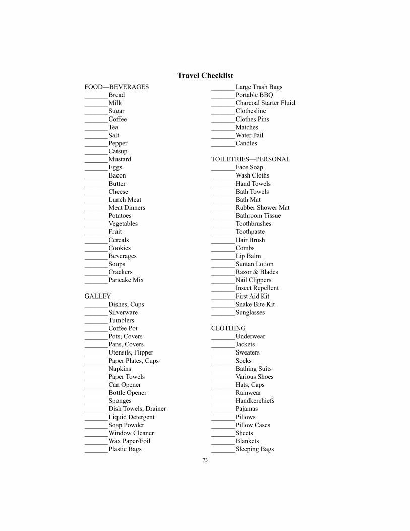
73
Travel Checklist
FOOD—BEVERAGES
_______Bread
_______Milk
_______Sugar
_______Coffee
_______Tea
_______Salt
_______Pepper
_______Catsup
_______Mustard
_______Eggs
_______Bacon
_______Butter
_______Cheese
_______Lunch Meat
_______Meat Dinners
_______Potatoes
_______Vegetables
_______Fruit
_______Cereals
_______Cookies
_______Beverages
_______Soups
_______Crackers
_______Pancake Mix
GALLEY
_______Dishes, Cups
_______Silverware
_______Tumblers
_______Coffee Pot
_______Pots, Covers
_______Pans, Covers
_______Utensils, Flipper
_______Paper Plates, Cups
_______Napkins
_______Paper Towels
_______Can Opener
_______Bottle Opener
_______Sponges
_______Dish Towels, Drainer
_______Liquid Detergent
_______Soap Powder
_______Window Cleaner
_______Wax Paper/Foil
_______Plastic Bags
_______Large Trash Bags
_______Portable BBQ
_______Charcoal Starter Fluid
_______Clothesline
_______Clothes Pins
_______Matches
_______Water Pail
_______Candles
TOILETRIES—PERSONAL
_______Face Soap
_______Wash Cloths
_______Hand Towels
_______Bath Towels
_______Bath Mat
_______Rubber Shower Mat
_______Bathroom Tissue
_______Toothbrushes
_______Toothpaste
_______Hair Brush
_______Combs
_______Lip Balm
_______Suntan Lotion
_______Razor & Blades
_______Nail Clippers
_______Insect Repellent
_______First Aid Kit
_______Snake Bite Kit
_______Sunglasses
CLOTHING
_______Underwear
_______Jackets
_______Sweaters
_______Socks
_______Bathing Suits
_______Various Shoes
_______Hats, Caps
_______Rainwear
_______Handkerchiefs
_______Pajamas
_______Pillows
_______Pillow Cases
_______Sheets
_______Blankets
_______Sleeping Bags
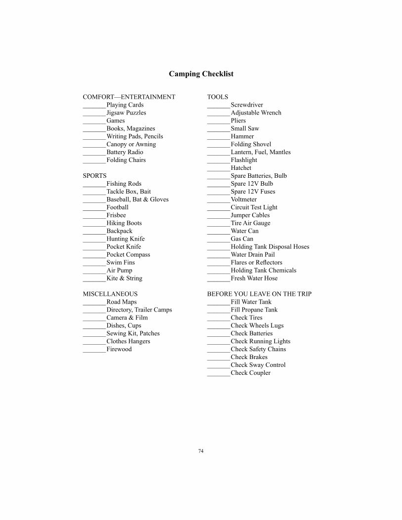
74
Camping Checklist
COMFORT—ENTERTAINMENT
_______Playing Cards
_______Jigsaw Puzzles
_______Games
_______Books, Magazines
_______Writing Pads, Pencils
_______Canopy or Awning
_______Battery Radio
_______Folding Chairs
SPORTS
_______Fishing Rods
_______Tackle Box, Bait
_______Baseball, Bat & Gloves
_______Football
_______Frisbee
_______Hiking Boots
_______Backpack
_______Hunting Knife
_______Pocket Knife
_______Pocket Compass
_______Swim Fins
_______Air Pump
_______Kite & String
MISCELLANEOUS
_______Road Maps
_______Directory, Trailer Camps
_______Camera & Film
_______Dishes, Cups
_______Sewing Kit, Patches
_______Clothes Hangers
_______Firewood
TOOLS
_______Screwdriver
_______Adjustable Wrench
_______Pliers
_______Small Saw
_______Hammer
_______Folding Shovel
_______Lantern, Fuel, Mantles
_______Flashlight
_______Hatchet
_______Spare Batteries, Bulb
_______Spare 12V Bulb
_______Spare 12V Fuses
_______Voltmeter
_______Circuit Test Light
_______Jumper Cables
_______Tire Air Gauge
_______Water Can
_______Gas Can
_______Holding Tank Disposal Hoses
_______Water Drain Pail
_______Flares or Refl ectors
_______Holding Tank Chemicals
_______Fresh Water Hose
BEFORE YOU LEAVE ON THE TRIP
_______Fill Water Tank
_______Fill Propane Tank
_______Check Tires
_______Check Wheels Lugs
_______Check Batteries
_______Check Running Lights
_______Check Safety Chains
_______Check Brakes
_______Check Sway Control
_______Check Coupler

75
Service To Be Performed Service Interval Each 1,000 3,000 5,000 10,000 Trip Miles Miles Miles Miles or 30 90 Six Yearly Weekly Days Days Months
Pack Wheel Bearings �
Inspect Brakes �
Inspect Safety Chains �
Inspect Brake Wiring �
Inspect Tires �
Inspect Hitch Components �
Lubricate Locks �
Lubricate Coupler Latch & Socket �
Lubricate Hinges �
Inspect + Clean Vents �
Torque Lug Nuts �
Sanitize Water Tanks �(if trailer has been stored)
Clean Drapes + Interior Fabrics �
Clean Battery Cables & �Terminals / Check Fluid
Inspect Suspension �
Check All Seams + Openings �Reseal as Needed
Check Water System Components �
Maintenance RequirementsMaintenance intervals, checks, and inspections as prescribed in this manual are
necessary to keep your vehicle in good working condition. Any damage caused by failure to follow recommended maintenance may not be covered by warranty.
Recommended Maintenance Schedule

76
Warranty Information
Air Conditioner
Manufacturer ____________________________________________________________
Model _________________________________________________________________
Serial Number ___________________________________________________________
Microwave Oven
Manufacturer ____________________________________________________________
Model _________________________________________________________________
Serial Number ___________________________________________________________
Stereo
Manufacturer ____________________________________________________________
Model _________________________________________________________________
Serial Number ___________________________________________________________
Generator
Manufacturer ____________________________________________________________
Model _________________________________________________________________
Serial Number ___________________________________________________________
Miscellaneous
Key Number ____________________________________________________________
_______________________________________________________________________
_______________________________________________________________________
_______________________________________________________________________
_______________________________________________________________________
_______________________________________________________________________
_______________________________________________________________________
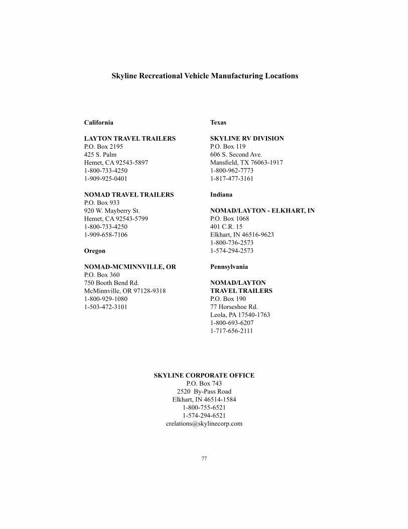
77
Skyline Recreational Vehicle Manufacturing Locations
California
LAYTON TRAVEL TRAILERS
P.O. Box 2195
425 S. Palm
Hemet, CA 92543-5897
1-800-733-4250
1-909-925-0401
NOMAD TRAVEL TRAILERS
P.O. Box 933
920 W. Mayberry St.
Hemet, CA 92543-5799
1-800-733-4250
1-909-658-7106
Oregon
NOMAD-MCMINNVILLE, OR
P.O. Box 360
750 Booth Bend Rd.
McMinnville, OR 97128-9318
1-800-929-1080
1-503-472-3101
Texas
SKYLINE RV DIVISION
P.O. Box 119
606 S. Second Ave.
Mansfi eld, TX 76063-1917
1-800-962-7773
1-817-477-3161
Indiana
NOMAD/LAYTON - ELKHART, IN
P.O. Box 1068
401 C.R. 15
Elkhart, IN 46516-9623
1-800-736-2573
1-574-294-2573
Pennsylvania
NOMAD/LAYTON
TRAVEL TRAILERS
P.O. Box 190
77 Horseshoe Rd.
Leola, PA 17540-1763
1-800-693-6207
1-717-656-2111
SKYLINE CORPORATE OFFICE
P.O. Box 743
2520 By-Pass Road
Elkhart, IN 46514-1584
1-800-755-6521
1-574-294-6521

78
Index
Air Conditioner ................................................................................................................45
Antenna, TV .....................................................................................................................46
Beds..................................................................................................................................40
Brake Inspection and Adjustment ....................................................................................14
Braking Tips .....................................................................................................................14
Breakaway Switch ...........................................................................................................13
Carbon Monoxide Detector ..............................................................................................53
Condensation ....................................................................................................................31
Connector Plug .................................................................................................................13
Door Lock Assembly, Bathroom ......................................................................................44
Doors ................................................................................................................................35
Doors, Access ...................................................................................................................35
Drainage System ..............................................................................................................21
Electrical System .............................................................................................................30
Fueling Station......................................................................................................... ........37
Furnace, Gas ....................................................................................................................50
Propane Detector ..............................................................................................................52
Generator ............................................................................................................ .............36
Hitching Information .........................................................................................................7
Propane Manual Regulator ..............................................................................................23
Propane System ................................................................................................................22
Monitor Panel ...................................................................................................................47
Oven, Kitchen ..................................................................................................................45
Radio, AM-FM CD Player ...............................................................................................47
Grill, Exterior .................................................................................................. ............... 39
Range Hood .....................................................................................................................45
Range, Kitchen .................................................................................................................45
Refrigerator ......................................................................................................................45
Smoke Alarm ...................................................................................................................52
Stabilization .....................................................................................................................17
Steps .................................................................................................................................35
Storage Compartments .......................................................................................................5
Swaying and Fishtailing of Trailer .....................................................................................2
Tables ...............................................................................................................................40
Tire, Changing .................................................................................................................11
Tire, Information ................................................................................................................9
Toilet ................................................................................................................................47
Towing Instructions .........................................................................................................15
Towing Speed ...................................................................................................................15
Towing Stability ...............................................................................................................15
Travel Trailer and Fifth Wheel Slide-Out Room
Adjustment and Operation ...............................................................................................57
Ventilation ........................................................................................................................31
Water Heater ....................................................................................................................50
Water System ...................................................................................................................19
Windows ..........................................................................................................................35
Winterizing .......................................................................................................................61

79
Of course, you love the RV lifestyle. And your Skyline-built RV. But
you still need a home base. A place you can head for when your holiday
is history.
You need a home loaded with style, comfort, and convenience. A low-
maintenance home with all the space and features you want. At a price
you can afford.
So if you’re thinking about owning a home that won’t own you, it’s
time to check out the homes built and backed by Skyline. For more
than 53 years, Skyline’s been building America’s best. Because Skyline
people understand that even for an RVer, nothing’s more important than
home sweet home.
For the name of your nearest retailer of Skyline-built homes, write Mar-
keting Department, Skyline Corporation, Post Offi ce Box 743, Elkhart,
Indiana 46515-0743. Or visit us at our Web Site, at www.skylinecorp.
com.
© 2000 Skyline Corporation, Elkhart, Indiana
WHEN YOU’RE READY TO
HEAD FOR HOME

CORPORATE MISSION STATEMENT
Skyline Corporation is a leader in the development, manufacture, and marketing of high quality, innovative manufactured homes and recreational vehicles that meet customer needs for housing and leisure lifestyles.
Our mission is to continually improve the quality of our products and the way we do business in order to meet customers’ expectations. By pursuing this mission, we will be able to grow and prosper as a business, provide stable employment and a high quality of work life for our people, be a responsible community citizen, and return a reasonable profi t to our shareholders.
Our mission refl ects our deeply held Corporate values and principles and its achievement involves these areas:
SAFETY...
We will provide a safe work environment for our people and safe products for our customers.
QUALITY...We will provide products and services that consistently meet customer needs and exceed expectations for quality.
CONTINUOUS IMPROVEMENT...We will continually strive for excellence in everything we do. We will constantly seek day-to-day and long-term improvements and not settle for short-term “fi xes.”
CUSTOMER FOCUS...Customers are the ultimate reason Skyline is in business and everyone at Skyline must direct his or her efforts to the production of products that exceed customer expecta-tions. Every activity and every job in the Company is part of this process.
PEOPLE...People are our greatest asset. We will listen to and respect ideas from everyone and will involve our people in the decisions that affect the areas in which they work. We will continually encourage and provide training and educational opportunities for our people, so that they can optimize their performance, their individual development, and their contribution to the Company.
TEAMWORK...Teamwork is the driving force of the Skyline organization, enabling us to coordinate the Company’s resources to achieve the Company’s mission. The essence of team-work is breaking down barriers between departments and treating each person and each job as a customer whose needs must be met if the ultimate customer, the buyer of a Skyline product, is to be satisfi ed.
INTEGRITY...We will conduct all of our activities in a manner which is at all times fair, moral, ethical, and legal. We will hire, reward and promote without discrimination and without regard to age, sex, ethnic origin, physical condition, or religious belief.
DEALERS & SUPPLIERS...We view our dealers and suppliers as exten-sions of our Company. We will conduct our business in an atmosphere of trust and work to form mutually benefi cial long-term partnerships.
PROFITS...Profi ts are the ultimate measure of how ef-fi ciently we satisfy our customers’ desire for products of superior value. We will strive to achieve the profi ts required for survival and growth and to provide jobs and security for our people.

NOTES

NOTES

Corporate Offi ce — P.O. Box 743 — Elkhart, Indiana 46514-1584
1-800-755-6521
05/05