trailer owners manual - · pdf filecoupling tractor semi-trailers step 1. inspect fifth...
TRANSCRIPT

1
Operator’s Instructions
This manual was prepared to acquaint you with the operation and maintenance of your Cornhusker 800 trailer and to provide important safety information. We stress the importance of regular safety checks and inspections for the safe and efficient operation of your trailer.
Please read your operator’s manual carefully and have a full understanding prior to using your trailer or performing any maintenance. We urge you to contact Truck Equipment Service Company at 402-476-3225 should you have any questions. When it comes to service, keep in mind that your Cornhusker 800 dealer knows your trailer best and is interested in your complete satisfaction. Your dealer invites you to return for all of your service needs, both during and after the warranty period.
This manual provides a general safety and maintenance overview. For more specific information, consult the individual parts manuals. This manual includes the latest information at the time that it was printed. We reserve the right to make changes in the product after that time without further notice. Date issued: 05/15/1999

2
Table of Contents
Safety and Information Labels 3-7 Safety Instructions 8 Landing Gear 8 Shur-Lok Roll Up Tarp 8 Coupling & Uncoupling 9-12 Weight & Balance 13 Driver’s Pre-Trip Inspection 14-16 Air System & Brakes 17-21 Care & Maintenance of Brakes Recommended Periodic Service Air System & Brake Operation Brake Safety Check Parking Brakes Automatic Slack Adjuster Tires 22 Tire Loads Spare Tire Rims & Wheels 23-26 Installation Procedure Rim & Wheel Maintenance & Inspection Axles & Suspensions 27-29
Bearing Adjustment Wheel Hubs and Seals
Axle Alignment 30-31 Sliders & Fixed Suspension Hendrickson Suspensions w/ Quik Align Collars Leaf Spring Alignment Suspension System 32-35 Leaf Suspension Air Suspension Troubleshooting Wiring Diagram for Hopper Trailers 36 Rock Pups – Dump Boxes - Hoists 37-41 Safety/General Information General Operation Instructions General Maintenance Instructions Rock Pup Coupling Operation and Maintenance Tailgate Lock Adjustment Dealer List 42 TESCO Phone Directory 43 Warranty Information 44 References 45 Appendix: Other Wiring Diagrams Warranty
3
Safety Decals
The following terms are used to call your attention to instructions involving your personal safety and the safety of others. Failure to follow these instructions can result in injury or death. Danger-Indicates an imminently hazardous situation that, if not avoided, will result in death or
serious injury. Warning -Indicates a potentially hazardous situation that, if not avoided, could result in death or
serious injury. Caution-Indicates a potentially hazardous situation that, if not avoided, may result in minor or
moderate injury.
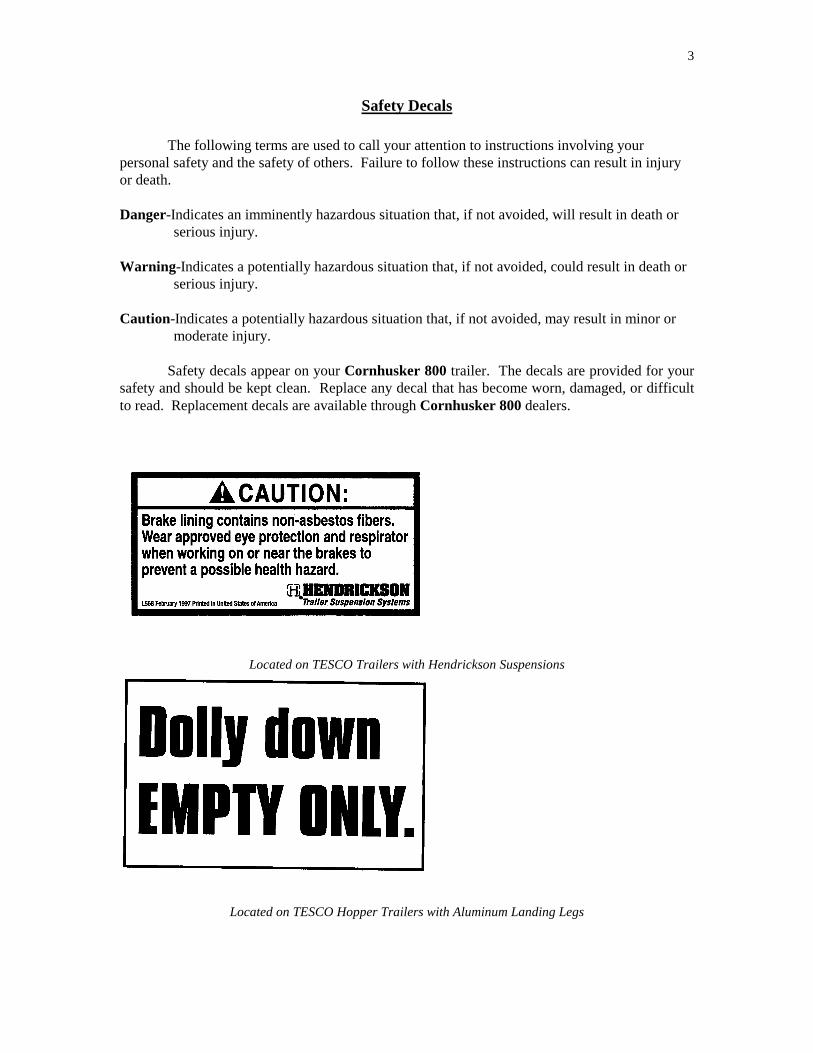
Safety decals appear on your Cornhusker 800 trailer. The decals are provided for your safety and should be kept clean. Replace any decal that has become worn, damaged, or difficult to read. Replacement decals are available through Cornhusker 800 dealers.
Located on TESCO Trailers with Hendrickson Suspensions
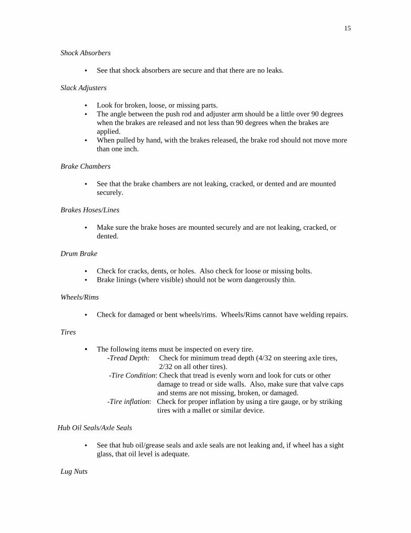
Located on TESCO Hopper Trailers with Aluminum Landing Legs

4
Located on TESCO Aluminum Dump Boxes
Located on TESCO Aluminum Dump Boxes
Located on TESCO Aluminum Dump Boxes

5
Located on TESCO Products with SHURLOK Tarps
Located on Tire Carrier Member
Located on TESCO Combination Trailers

6
Located on TESCO Aluminum Dump Boxes
Located on TESCO Trailers with Hutch Suspensions

7
Located on TESCO Trailers with Hendrickson Suspensions
Located on TESCO Trailers with Neway Suspensions

8
Safety Instructions
Ladder Safety Inspection
• Inspect for worn, damaged or missing parts before each use. • Never use a ladder with damaged, missing, worn or loose parts. • Make sure all rivets, nuts, bolts, braces and joints are tight: steps and rungs secure. • Never make temporary repairs of damaged ladders or parts.
Proper climbing and use
• Do not use ladders if you tire easily, are subject to fainting spells, use medicine or alcohol, or are physically handicapped.
• If ladders are wet, iced or for some reason seem to be slippery, they must not be used.
• Ladder is designed to support the weight of one person. • Use extreme caution getting on and off the ladder. • Front ladder: You must use a step ladder, or other structure specifically designed for
the purpose of ascent and descent, and of an adequate height to safely reach the bottom ladder rung.
• Face ladder when climbing up or down. • Maintain a firm grip. Use both hands in climbing. • Hands must be free. • Keep your shoes clean and never use leather soles. • Never drop or apply an impact to the ladder. • Never climb over the top of the trailer and enter the inside compartment for any
reason. • Do not use the top rails as walkways.
Landing Gear
- Make sure landing gear is fully raised with no missing parts, and is not bent or otherwise
damaged. - Crank handle must be in place and secured.
Shur-Lok Roll up Tarp - Note safety stickers on trailer. - Tarp must be kept to a recommended 40-60 lbs. of tension or excessive tarp wear may occur. - Do not stand or walk on the end caps. - Do not operate this vehicle at highway speeds while the tarp system is in the “open” position. - Hold crank firmly with both hands while operating.
Coupling and Uncoupling

9
Knowing how to couple and uncouple correctly is basic to the safe operation of
combination vehicles. General coupling and uncoupling steps are listed below. There are differences between rigs, so learn the details of coupling and uncoupling the trucks you will operate. Coupling Tractor Semi-Trailers Step 1. Inspect Fifth Wheel • Check for damaged/missing parts.
• Check to see that mounting to tractor is secure, no cracks in frame, etc. • Be sure that the fifth wheel plate is greased as required. Failure to keep the fifth
wheel plate lubricated could cause steering problems because of friction between the tractor and the trailer.
• Check if fifth wheel is in proper position for coupling: -Wheel tilted down towards rear of tractor. -Jaws open.
-Safety unlocking handle in the automatic lock position. • If you have a sliding fifth wheel, make sure it is locked. • Make sure the trailer kingpin is not bent or broken.
Step 2. Inspect Area and Chock Wheels
• Make sure area around the vehicle is clear. • Be sure trailer spring brakes are on. • Check tarp to make sure it’s properly closed. • Check traps to make sure they’re properly closed and locked.
Step 3. Position Tractor
• Put the tractor directly in front of the trailer. (Never back under the trailer at an angle, because you might push the trailer sideways and break the landing gear.)
• Check position, using outside mirrors, by looking down both sides of the trailer. Step 4. Back Slowly
• Back until fifth wheel just touches the trailer. • Don’t hit the trailer.
Step 5. Secure Tractor
• Put on the parking brake. • Put transmission in neutral.
Step 6. Check Trailer Height
• The trailer should be low enough that it is raised slightly by the tractor when the

10
tractor is backed under it. Raise or lower the trailer as needed. (If trailer is too low, tractor may strike and damage nose of trailer; if trailer is too high, it may not couple correctly.)
• Check that the kingpin and fifth wheel are aligned.
Step 7. Connect Air Lines to Trailer
• Check glad hand seals and connect tractor supply (emergency) air line to trailer supply (emergency) glad hand.
• Check glad hand seals and connect tractor control (service) air line to trailer control (service) glad hand.
• Make sure air lines are safely supported where they won’t be crushed or caught while tractor is backing under the trailer.
Step 8. Supply Air to Trailer
• From cab, push in “air supply” knob or move tractor protection valve control from the “emergency” to the “normal” position to supply air to the trailer brake system.
• Wait until the air pressure is normal. • Check brake system for crossed air lines. -Shut engine off so you can hear the brakes. -Apply and release trailer brakes, listen for sound of trailer brakes being applied and released. You should hear the brakes move when applied and air escape when the brakes are released. -Check air brake system pressure gauge for signs of major air loss. • When you are sure trailer brakes are working, start engine. • Make sure air pressure is up to normal.
Step 9. Lock Trailer Brakes
• Pull out the “air supply” knob, or move the tractor protection valve control from “normal” to “emergency.”
Step 10. Back Under Trailer
• Use lowest reverse gear. • Back tractor slowly under trailer to avoid hitting the kingpin too hard. • Stop when the kingpin is locked into the fifth wheel.
Step 11. Check Connection for Security
• Raise trailer landing gear slightly off ground. • Pull tractor gently forward while the trailer brakes are still locked onto the tractor.
Step 12. Secure Vehicle
• Put transmission in neutral. • Put parking brakes on. • Shut off engine and take key with you so someone else won’t move truck while you

11
are under it. Step 13. Inspect Coupling
• Use a flashlight if necessary. • Make sure there is no space between upper and lower fifth wheel. If there is space,
something is wrong (kingpin may be on top of closed fifth wheel jaws; trailer would come loose very easily).
• Go under trailer and look into the back of the fifth wheel. Make sure the fifth wheel jaws have closed around the shank of the kingpin.
• Check that the locking lever is in the “lock” position. • Check that the safety catch is in position over locking lever. (On some fifth wheels
the catch must be put in place by hand.) • If the coupling isn’t right, don’t drive the coupled unit; get it fixed.
Step 14. Connect the Electrical Cord and Check Air Lines
• Plug the electrical cord into the trailer and fasten the safety catch. • Check both air lines and electrical lines for signs of damage. • Make sure air and electrical lines will not hit any moving parts of vehicle.
Step 15. Raise Front Trailer Supports (Landing Gear)
• Use low gear range (if so equipped) to begin raising the landing gear. Once free of weight, switch to the high gear range.
• Raise the landing gear all the way up. (Never drive with landing gear only part way up as it may catch on railroad tracks or other objects.)
• After raising landing gear, secure the crank handle safely. • When full weight of trailer is resting on tractor:
-Check for enough clearance between rear of tractor frame and landing gear. (When tractor turns sharply it must not hit landing gear.) -Check that there is enough clearance between the top of the tractor tires and the nose of the trailer.
Uncoupling Tractor Semi-Trailers The following steps will help you to uncouple safely. Step 1. Position Rig
• Make sure surface of parking area can support weight of trailer. • Have tractor lined up with the trailer. (Pulling out at an angle can damage landing
gear.) Step 2. Ease Pressure on Locking Jaws
• Shut off trailer air supply to lock trailer brakes. • Ease pressure on fifth wheel locking jaws by backing up gently (this will help you release the
fifth wheel locking lever). • Put parking brakes on while tractor is pushing against the kingpin. This will hold rig with

12
pressure off the locking jaws. Step 3. Lower the Landing Gear
• If trailer is empty, lower the landing gear until it makes firm contact with the ground, turn crank in low gear a few extra turns; this will lift some weight off the tractor. (Do not lift trailer off the fifth wheel.) This will:
-make it easier to unlatch fifth wheel -make it easier to couple next time
Step 4. Disconnect Air Lines and Electrical Cable
• Disconnect air lines from trailer. Connect air line glad hands to dummy couplers at back of cab, or couple them together.
• Hang electrical cable with plug down to prevent moisture from entering it. • Make sure lines are supported so they won’t be damaged while driving the tractor.
Step 5. Unlock Fifth Wheel
• Raise release handle lock. • Pull the release handle to “open” position. • Keep legs and feet clear of the rear tractor wheels to avoid serious injury in case the vehicle
moves. Step 6. Pull Tractor Partially Clear of Trailer
• Pull tractor forward until fifth wheel comes out from under the trailer. • Stop with tractor frame under trailer (prevents trailer from falling to ground if landing gear
should collapse or sink). Step 7. Secure Tractor
• Apply parking brake. • Place transmission in neutral.
Step 8. Inspect Trailer Supports
• Make sure ground is supporting trailer. • Make sure landing gear is not damaged.
Step 9. Pull Tractor Clear of Trailer
• Release parking brakes. • Check the area and drive tractor clear.

13
Weight & Balance
You are responsible for not being overloaded. Definitions you should know:
Gross vehicle weight (GVW ): The total weight of a single vehicle plus its load.
Gross combination weight (GCW): The total weight of a powered unit plus trailer(s) plus the cargo.
Gross vehicle weight rating (GVWR ): The maximum GVW specified by the manufacturer for a single vehicle plus its load.
Gross combination weight rating (GCWR): The maximum GCW specified by the
manufacturer for a specific combination of vehicles plus its load.
Axle weight: The weight transmitted to the ground by one axle or one set of axles. Tire load: The maximum safe weight a tire can carry at a specified pressure. This rating
is stated on the side of each tire. Legal Weight Limits � You must keep weights within legal limits. States have maximums for GVW’s, GCW’s and
axle weights. Often, maximum axle weights are set by a bridge formula. � Overloading can have bad effects on steering, braking, and speed control. Overloaded trucks
have to go very slow on upgrades, and worse, they may gain too much speed on downgrades. Stopping distance increases. Brakes can fail when forced to work too hard.
� During bad weather or in mountains, it may not be safe to operate at legal maximum weights.
Take this into account before driving. � The GAWR and tire information shown on the vehicle identification plate was applicable at
the time the trailer was manufactured. If the tires or other components of the running gear have been changed or altered since the trailer was manufactured, the GAWR may have changed.

14
Driver’s Pre-Trip Inspection Air/Electrical Connections
• Check that trailer air connectors are sealed and in good condition. • Make sure glad hands are locked in place, free of damage or air leaks. • Make sure the trailer electrical plug is firmly seated and locked in place.
Lights/Reflectors
• Check that all external lights and reflective equipment are clean and functional. • Light and reflector checks include:
- Clearance lights (red on rear, amber elsewhere) - Headlights (high and low beams) - Tail lights - Turn signals - 4-way flashers - Brake lights - Red reflectors (on rear) and amber reflectors (elsewhere)
Tarp
• Check that tarp is mounted and fastened securely. Landing Gear
• Check that the landing gear is fully raised, has no missing parts, crank handle is secure, and the support frame is not damaged.
Doors/Traps
• If equipped, check that doors are not damaged. Check that doors open, close, and latch properly from the outside.
• Check that traps are fully closed and locked. Springs/Air/Torque
• Look for missing, shifted, cracked, or broken leaf springs. • If vehicle is equipped with torsion bars, torque arms, or other types of suspension
components, check that they are not damaged and are mounted securely. • Air ride suspension should be checked for damage and leaks.
Mounts
• Look for cracked or broken spring hangers, missing or damaged bushings, and broken, loose, or missing bolts, U-bolts or other axle mounting parts.
• The mounts should be checked at each point where they are secured to the vehicle frame and axle(s).
15
Shock Absorbers
• See that shock absorbers are secure and that there are no leaks. Slack Adjusters
• Look for broken, loose, or missing parts. • The angle between the push rod and adjuster arm should be a little over 90 degrees
when the brakes are released and not less than 90 degrees when the brakes are applied.
• When pulled by hand, with the brakes released, the brake rod should not move more than one inch.
Brake Chambers
• See that the brake chambers are not leaking, cracked, or dented and are mounted securely.
Brakes Hoses/Lines
• Make sure the brake hoses are mounted securely and are not leaking, cracked, or dented.
Drum Brake
• Check for cracks, dents, or holes. Also check for loose or missing bolts. • Brake linings (where visible) should not be worn dangerously thin.
Wheels/Rims
• Check for damaged or bent wheels/rims. Wheels/Rims cannot have welding repairs. Tires
• The following items must be inspected on every tire. -Tread Depth: Check for minimum tread depth (4/32 on steering axle tires,
2/32 on all other tires). -Tire Condition: Check that tread is evenly worn and look for cuts or other
damage to tread or side walls. Also, make sure that valve caps and stems are not missing, broken, or damaged.
-Tire inflation: Check for proper inflation by using a tire gauge, or by striking tires with a mallet or similar device.
Hub Oil Seals/Axle Seals
• See that hub oil/grease seals and axle seals are not leaking and, if wheel has a sight glass, that oil level is adequate.
Lug Nuts

16
• Check that all lug nuts are present, free of cracks and distortions, and show no signs of looseness such as rust trails or shiny threads.
• Make sure all nut holes are not cracked or distorted. Spacers
• If equipped, check that spacers are not bent, damaged, or rusted through. • Spacers should be evenly centered, with the dual wheels and tires evenly separated.
Frame
• Look for cracks, broken welds, holes or other damage to the frame, cross members, box, and floor.
Splash Guards
• Check that splash guards or mud flaps are not damaged and are mounted securely. Pull Trailer Drawbars
• Check dolly tongue for cracks. • Check safety cable. • Check pintle hook to insure it’s locked. • Check air and electrical connections.
17
Air System & Brakes Care & Maintenance of Brakes
- Do not abuse your brakes, maintain them. - Inspect and adjust frequently. - Brakes that are out of adjustment can:
- Increase stopping distance. - Shorten brake component life. - Increase chance for trailer to jackknife.
Recommended Periodic Service
- Trailer Adjustment Inspection1 - 1. Connect an auxiliary air system to the SUPPLY or EMERGENCY port of the trailer
air system. - 2. Increase the air pressure to 100 psi MINIMUM to release the spring chambers. - 3. With the brakes NOT APPLIED, measure the distance from the bottom of the air
chamber to the center of the large clevis pin on all the brakes. Record each dimension. - 4. Connect a second auxiliary air system to the SERVICE port of the trailer air system. - 5. Increase the air pressure of the second air system to 85 psi to apply the service brakes. - 6. Repeat step 3 and measure WITH THE SERVICE BRAKES APPLIED. Record each
dimension. - 7. Calculate the adjusted chamber stroke of each brake:
- A. Subtract the dimension that was measured in step 3 from the dimension measured in step 6.
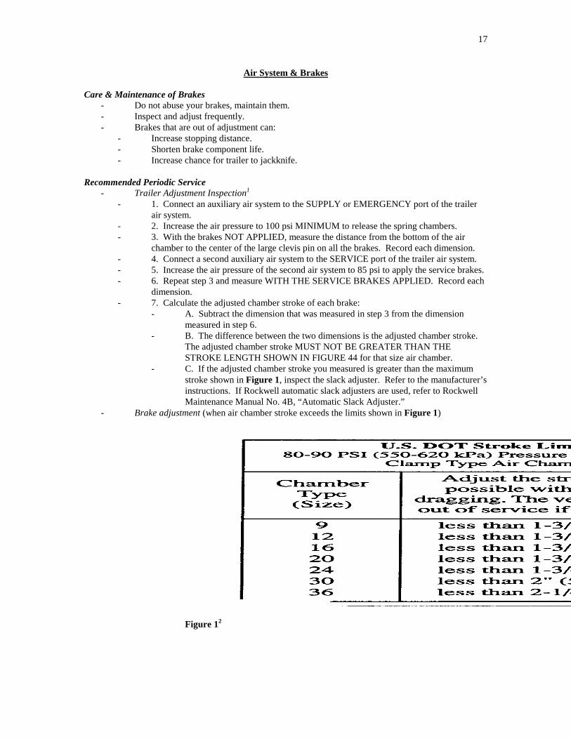
- B. The difference between the two dimensions is the adjusted chamber stroke. The adjusted chamber stroke MUST NOT BE GREATER THAN THE STROKE LENGTH SHOWN IN FIGURE 44 for that size air chamber.
- C. If the adjusted chamber stroke you measured is greater than the maximum stroke shown in Figure 1, inspect the slack adjuster. Refer to the manufacturer’s instructions. If Rockwell automatic slack adjusters are used, refer to Rockwell Maintenance Manual No. 4B, “Automatic Slack Adjuster.”
- Brake adjustment (when air chamber stroke exceeds the limits shown in Figure 1)
Figure 12
-

18
Figure 23
Figure 34
- Automatic Slack Adjustment5 - Caution: Do not set the free stroke shorter than the minimum specified setting. If the free
stroke is too short, the linings may drag and damage the brake. - If it is necessary to adjust the stroke, disengage the pawl and turn the adjusting nut 1/8
turn in the direction shown in Figure 2 and check the stroke again. Continue to measure and adjust the stroke until it is adjusted correctly.
- Note: It is not necessary to remove a “pull” pawl design assembly during installation, adjustment or when “backing off” the brakes. - Use a screwdriver or equivalent tool to lift the button on the pawl assembly. - Lift the button at least 1/32-inch to disengage the “pull” pawl from the actuator. - Turn the adjusting nut on the slack adjuster in the required direction. - When finished, remove the screwdriver or tool. The “pull” pawl will engage
automatically. - Check the adjusted chamber stroke as illustrated in Figure 3.
- Measure from the air chamber to the center of the large clevis pin while the brake is released.
- Have another person apply the brakes using 80-90 psi of air pressure. - Lubrication – lubricate the brake and slack adjuster according to schedule. - Minor Inspection – at each lubrication. - Brake Reline – when the thickness of the lining is ¼ inch (6.3 mm) at its thinnest point. - Drums – check at reline. - Major Inspection – at each reline. - Complete Overhaul – at every second reline or as required. - Note:

19
- A schedule for periodic adjustment, cleaning, inspection and lubrication of the brake equipment must be made.
- Brakes must be adjusted as frequently as required for correct operation and safety. The adjustments must give correct clearance between the lining and drum, correct pushrod travel and correct balance between the brakes.
- Caution: Do not let brake lining wear to the point that the rivets of bolts touch the drum; - damage to the drum will occur. - During a major overhaul, the following parts must be carefully checked and replaced with
genuine Rockwell Replacement Parts if required: - Backing plates or spiders for distortion and loose bolts. - Anchor pins for wear and correct alignment. - Brake shoes for wear at anchor pin holes or roller slots. - Camshaft and camshaft bushings for wear. - Shoe return springs must be replaced. - Brake linings for grease on the lining, wear and loose rivets or bolts. - Drums for cracks, deep scratches or other damage.
- It’s recommended that springs, rollers and anchor pins be replaced at each reline.
Air System & Brake Operation
- Make sure there is a firm seal between air brake glad hands. - Inspect glad hands for rubber washer damage and cracked housing. - Inspect air hoses for cracking and for frayed connections. - Keep air system clean.
- Drain primary and emergency air tanks daily to remove moisture and contaminants, especially in cold weather.
- Use of air line antifreeze may result in deterioration of seals. - If using Teflon tape or other thread sealers to seal threaded airline connections, don’t let
pieces of sealer enter the air system – they will clog passages into valves. - Keep the air system tight:
- If there are leaks, it will not charge properly. - Check the tractor pressure gauge for unusual drops or extended build up times.
- Inspection Procedure - Run tractor engine until air brake system pressure gauge shows at least 70 psi.
- Listen for air leaks. - With engine off:
- Check gauge reading with no brakes applied. - Gauge reading loss should not exceed 3 pounds in 1 minute.
- Apply brakes fully for 2 minutes. - Gauge reading loss should not exceed 4 pounds per minute. - Slowly open a drain cock in an emergency or supply line and allow the
pressure to drop gradually. - In a system without spring brake control valves, the relay emergency valve should function
and apply the brakes. - In a system with spring brake control valves, spring brakes should function and apply brakes. - Caution: Serious air losses are extremely hazardous and are likely to cause accidents or
breakdowns. - Warning: Do not operate this vehicle with any brake defects or with brakes out of
adjustment.

20
Brake Safety Check
- Before you enter traffic, try the foot pedal, emergency dash control valve (push, pull or flip) and trailer brake lines to assure brake application and release. - Listen for air leaks.
- Check slack adjusters . Parking Brakes
- This system complies with all FMVSS-121 requirements, which allow 3 methods for emergency release of the parking brake. - Note: Air pressure is required to release the parking brake. - 1. Protected Reservoir: System will retain enough reservoir pressure to release the
spring brake actuators at least once by means of the parking brake control.
- 2. Spring Brake Priority: Spring brake can be released by re-pressuring the trailer supply line.
- 3. Service Brake Priority: If an air leak exists in the service brake reservoir, it must be repaired before the parking/emergency brake can be released.
- Danger: Parking brakes can also be released manually using a built in manual release. This should only be used to move the trailer to a safe location where repairs can be made. Install wheel chocks in front of and behind tires before manually releasing spring brakes. Failure to do this will result in death or serious injury.
- Danger: The spring brake chamber contains a highly loaded spring. Never attempt to disassemble the spring brake chamber. Our chamber includes a formed locking ring – never attempt to remove the locking ring. Failure to comply will result in death or serious injury.
- Warning: Never attempt to use the trailer for the majority of the braking effort by backing off the tractor brakes. This is illegal, unsafe, and will cause permanent failure of the trailer brake system. Failure to comply could result in serious injury or death.
Automatic Slack Adjuster6
- Inspect and lubricate the slack adjuster according to one of the following schedules. Use the schedule that gives the most frequent inspection and lubrication: - The schedule of chassis lubrication used by your fleet. - The schedule of chassis lubrication recommended by the chassis manufacturer. - Every six months. - A minimum of four times during the life of the linings.
- Also inspect and lubricate the slack adjuster whenever you reline the brakes. - 1. Before you do any maintenance on the brakes, check the free stroke and the adjusted
chamber stroke. - 2. Inspect the boot for cuts or other damage. If the boot is cut or damaged, remove the pawl
and inspect the grease. - If the grease is in good condition, install a new boot. - In a slack adjuster manufactured before 1993, when the grease is dry or contaminated, or
the pawl or actuator is dry or worn, remove the slack adjuster. - Disassemble the slack adjuster and replace any worn or damaged parts. - Use new seals and a new boot when you assemble the unit.

21
- 3. Lubricate the slack adjuster through the grease fitting. If necessary, install a camshaft into the ASA gear to minimize grease flow through the holes in the gear. Lubricate until new grease flows from around the inboard splines and from the pawl assembly.
- 4. Measure the gap between the clevis and the collar on a quick-connect clevis. Replace the clevis if the gap exceeds 0.060” (1.52 mm).
Figure 47

22
Tires
- Do not overinflate. - When tires are cold, check inflation with gauge (also check spare). - Inspect tires for objects in rubber or between duals. - Inspect tires for breaks or defects. - Watch new/retread tires for signs of failure during break-in period. - Dual tires on any axle end should have:
- The same diameter. - Equal air pressures. - Arrange air valve stems so both tires in a dual pair can be easily reached with air hose.
- Caution: Tires must be inflated according to the inflation pressure molded on the tire by the manufacturer according to law. - Tires must be matched with compatible rims. - Tires with fabric exposed through treads or sidewall, or with less that 2/32” tread depth
must be replaced. Tire Loads
- Do not overload tires; it is dangerous and unsafe. - Total load per tire must not exceed the manufacturer’s load carrying capacity at stated
inflation pressures for tires and rims. - TESCO puts a plate on every trailer with information on the Gross Axle Weight Rating
(GAWR). - The information on the plate was applicable at the time the trailer was built. If tires or
other running gear equipment have been changed or altered, the GAWR may have changed.
Spare Tire
- Use caution when handling tires and wheels – they are heavy. - When using/replacing the spare tire, move the trailer away from traffic to a solid, safe
working area. - To remove spare tire from the carrier:
- Unhook chain securing spare tire. - Pull the chain off the tire and remove the tire from the carrier.
- To replace the spare tire: - 1. Slide the spare into the tire carrier as far as it will go. Be sure the tire size and the
carrier match. - 2. Run the chain through the center of the tire and rim and back to the starting point.
Pull the chain ends together as tight as possible.
- 3. Secure the chain lock. - Inspection:
- Inspect carriers periodically according to usage. - Check for bent members and fatigue in welded or riveted joints. - Give close examination to the chain, chain retainer and chain fastener for signs of wear,
corrosion or fatigue. - Replace or repair bent or damaged members. - Weld joints or chains. - For chain replacement, use chain with 2850# tensile strength.

23
Rims and Wheels
- Put the best wheels on the front of the vehicle. - It is important to install rims and wheels properly.
- Use only the specified size of studs, nuts and clamps. Installation Procedure
- Wrenches for Demountable Rims and Disc Wheels: - Double-end socket wrenches for rims and disc wheels used with a 3-foot bar are
normally adequate to install and remove rims and wheels. - A 150 pound person, exerting their entire weight 2.5 feet out on a bar, can apply 375
foot-pounds of torque to a wrench (150 X 2.5). - Air wrenches are sometimes used to save time and labor.
- The torque they deliver depends on the air line pressure from which they operate.
- Periodic checks by torque wrench, or other means, should be done to make sure air wrenches are accurate.
- Disc Wheels - Check all parts for damage, including wheels and rings. - Make sure that studs, nuts, and mounting faces of hub and wheels are clean and free from
any grease. - Replace any defective parts. - Hub-piloted Mounting System8
- Before mounting hub-piloted wheels, coat the wheel pilot or hub pads generously with a lubricant like Freylube or an equivalent to minimize corrosion product build- up between the wheel and hub pilot. - Excessive corrosion build-up between the wheel and hub pilots makes wheel
removal difficult. - Do not lubricate the face of the wheel, hub, or brake drum.
- Wheel studs on both the right and left side hubs of vehicles utilizing the hub-piloted wheel system have right-hand threads.
- Before reinstalling two-piece flange nuts, lightly lubricate the stud threads and the contact surfaces between the cap nut and the washer with an SAE 30W oil to minimize corrosion between the mating surfaces. - Lubrication is not necessary with new hardware.
- Position one of the hub’s pilot pads at the twelve o’clock position. After positioning wheels on the pilot pads, hand tighten all two-piece flange nuts, then tighten to the recommended torque following the proper sequence shown in Figure 5 for your type wheel. - Two-piece flange nuts with a 33mm hex head design used with hub-piloted
wheels should be tightened to a torque of 450 foot-pounds. - Two-piece flange nuts with a 1 ½-inch hex head design and other designs have
different torque requirements. Get these from the
manufacturer. -

24
Figure 59 - Stud Located, Ball Seat Mounting System
- On these vehicles, wheel studs on the right side have right-hand threads and those on the left have left-hand threads. The “R” and “L” on the studs and nuts indicate right and left-hand threads respectively.
- After mounting a wheel over the studs, snug up the cap nuts in the order shown in Figure 6. After all the cap nuts have been snugged, tighten the cap nuts to the recommended torques, following the same tightening sequence.
- Inner and single cap nuts used with stud located wheels should be tightened to a torque of 450 foot-pounds if the threads are not lubricated; if they are lubricated, nuts should be tightened to 350 foot-pounds.
- Note: When dualing steel wheels with Alcoa aluminum wheels, follow the steel wheel manufacturer’s recommendations for proper torque and use of thread lubricants to mount the wheel.
Figure 610
- After vehicle has been operated for 50-100 miles, and every 2,000 to 4,000 miles thereafter, and during regular maintenance checks, rim nuts should be rechecked for proper torque.
- Caution: Do not intermix wheel types. Insufficient mounting torque can cause wheel shimmy, resulting in damage to parts and extreme tire tread wear. Excessive mounting torque can cause studs to break and discs to crack in the stud hole area.
Rim & Wheel Maintenance and Inspection11
- During Tire Inspections - 1. Check all metal surfaces thoroughly, looking for:
- Rust or corrosion buildup. - Cracks in metal. - Bent flanges. - Rim tool marks on rings or in gutter areas. - Loose, missing, or damaged nuts or clamps. - Bent or stripped studs. - Damaged or missing rim drive plates. - Matched rim parts.
-

25
- 2. Pull damaged rims or wheels.
- Caution: Excessively corroded or cracked rims/wheels can be dangerous – deflate tires before removing.
- 3. Mark damaged and hazardous areas with chalk. - 4. Replace damaged parts using proper sizes and types. - 5. Inflate tires to proper air pressures.
- During Tire Changes
- Warning: Wheels subjected to high pressure tire and rim separation (or other abuse) may no longer have sufficient dimension and contour to retain open side tire bead while under pressure. This will lead to explosive separation of tire and rim causing severe injury or death.
- Warning: Cracked wheels, loose lug nuts and missing studs are dangerous and likely to cause accidents.
- Warning: Do not rework, weld, heat or braze wheels for any reason. - 1. Thoroughly examine all metal surfaces, replace parts if you find damage. - 2. Check circumference of bend seat on the open side of the wheel (opposite the disc
face) with a bell tape. - If it does not match requirements, do not use.
- 3. Inspect the gutter area for: - Uneven seating of the side and lock ring, chipping of the gutter.
- Cause: projections on the side of the wheel gutter area. - Cracking of the bottom of the gutter flange.
- Thoroughly clean and inspect. - Look underneath gutter flange for circumferential cracks. - Note: Cracks lead to separation of rim from disc.
- 4. Inspect the mounting area for: - Stud hole cracks.
- Cause: improper torquing or excessive loading. - Stud hole cracks on hub/drum side of wheel.
- Cause: undersized diameter of wheel support surface (should be flat to at least 13 3/16”, though 13 ½” is preferred).
- 5. Inspect both sides of the disc area for band hole cracks. - 6. Inspect rim area.
- Check for nicks, gouges and cracks. - Cracks in areas around valve stem hole can cause loss of air.
- 7. Inspect for rim flange wear. - Irregular wear is caused by chafer area of the tire working on surface of rim
flange. - Replace if excessive.
- 8. Corrosion - Aluminum is naturally resistant to corrosion.
- Exceptions: Hauling livestock, salt, chloride compounds used in snow removal, or highly alkaline materials. Also, wet air in tubeless tires or wet tires.
- Remove mild corrosion with a wire brush. - Coat with Freylube or equivalent. - 9. Periodic Maintenance

26
- Carefully check lug nuts after the first 100 miles. Every 4 months check for wheel studs or nuts that may have worked loose.
- Tighten wheel nuts to these specifications (¾” – 16 or 1 – 1/8”-- 16) 450 to 500 foot lbs. Torque (dry).
- Note: Decal on side of trailer provides proper torque specifications and tightening sequence.
- Check hub gaskets and seals for oil leaks before each trip. - Leaking seals can ruin wheel bearings and possibly cause a failure of the axle-
wheel assembly. - Check oil level in hubs before every trip. Add oil when low – only to the level
marked on the hubcap – too much oil can damage the wheel bearings. - Use gear type oil: SAE 140 if temperature is above freezing, SAE 90 if
temperature is below freezing, or multipurpose oil with SAE range of 85-140 for year-round conditions.
- Change oil every 100,000 miles. - Check bearing cones for deterioration.

27
Axles & Suspensions
- Bearing adjustment12: The goal is to achieve proper end play in the wheel-end equipment. - On trailers with manual bearing adjustment, end play is done by tightening, then
backing off the adjusting nut of the wheel-retention hardware a prescribed amount. - End play must be between 0.001 –0.005 inches. - If end play is incorrect after following these procedures, corrections must be
made by backing the nut off a different amount. - Note: If tires are mounted on the wheels, wedge a pry bar under the tire to
make the following procedure easier. - To check end play:
- A. Attach the magnetic base of a dial indicator to the end of the spindle. Touch the dial indicator stem against the hub cap gasket face of the hub or spoke wheel.
- B. Slightly rotate the hub or spoke wheel in both directions while pushing inward until the dial indicator does not change. Set the dial indicator to zero.
- C. Slightly rotate the hub in both directions while pulling outward until the dial indicator does not change.
- D. The difference between the two readings is the end play. - Double Nut Manual Bearing Adjustment Procedure
- 1. Install the adjusting nut so that the pin on the nut faces away from the wheel-end equipment. Tighten the nut to 100 lb-ft (136 N•m) while rotating the hub of spoke wheel in both directions.
- 2. Completely loosen the nut, then tighten it to 50 lb-ft (68 N•m) while rotating the hub or spoke wheel in both directions.
- 3. Loosen the nut ¼ turn. Do not include socket backlash in the ¼ turn.
- 4. Install the lockwasher. If the hole in the washer is not aligned with the adjusting nut pin, remove the washer, turn it around and re-install. If the pin and hole are still not aligned, slightly adjust the parts to align them.
- 5. Install the jam nut. Tighten the nut to 250-300 lb-ft (340 – 408 N•m).
- 6. Check the end play as noted above. If end play does not meet specifications, remove the jam nut and lockwasher and tighten or loosen the adjusting nut as required to set proper end play.
- 7. Install the lockwasher and jam nut. - 8. Install the setscrew in the lockwasher. Tighten the setscrew
until it seats against the nut. - Oil-Lubricated Wheel Ends13
- 1. Rockwell trailer axle wheel ends most commonly have a designation of API-GL- 5 (American Petroleum Institute – Gear Lubricant No. 5). (See Figure 7)
- 2. Along with the GL-5 oils listed, oils with API grades GL-1, GL-2, GL-3 and GL-4 can also be used in trailer axle wheel ends. They cannot be used in drive axles, or in any application with hypoid, amboid, spiral bevel, or planetary gearing.
- 3. Oil viscosity should be appropriate for the climate in which the axle is used. - A. Low viscosity single grade oils, such as SAE 75W (Society of
Automotive Engineers), should only be used in cold climates. When using low viscosity oils, oil seals must be in excellent condition to insure against loss of fluids.
- B. Where vehicles operate in both warm and cold climates, multigrade oils, such as 80W/90, should be used.

28
- 4. Do not use thinning agents such as kerosene, gasoline, or other solvents that will lower the viscosity of lubricants.
- 5. Because contaminated lubricants can quickly wear internal wheel components, clean lubricants must be installed into the wheel-end on a maintenance interval which is appropriate to the application in which the axle is used.
- 6. Oil change frequency depends on the operating conditions, speeds and load of the vehicle. This information is just a general guideline. Some applications, such as container chassis and trailer on flat car service, put limited mileage on axles, allowing for greater maintenance intervals. Other applications may put severe stress on the wheel-end lubricant, requiring more frequent maintenance checks. - A. Whenever oil is contaminated or the wheel-end is disturbed by the
removal of the spoke wheel or hub, the oil should be changed. - B. For standard-duty on-highway service of more than 100,000 miles
(160,000 km) per year, change oil every 100,000 miles (160,000 km). For service of less than 100,000 miles (160,000 km) per year, change oil every 12 months.
- C. For heavy-duty on-highway, off-highway, or combined on/off-highway services of more than 60,000 miles a year, change oil every 30,000 miles (48,000 km). For service in which less than 60,000 miles (96,000 km) per year is accumulated, change oil every 6 months.
- 7. The wheel-end oil level should be inspected at least every 1,000 miles (1,600 km) if the vehicle is operated continuously in heavy-duty service. - - Make sure the vehicle is on level ground, then clean the hubcap window and
inspect. Add oil if it is more than 0.25 inch (6.3 mm) below its proper level.
Figure 7 14
-

29
Figure 8 15
- Wheel Hubs & Seals Maintenance
- Check hub bore for burrs. - Check spindle for imperfections. - Clean the whole wheel cavity thoroughly. - Place clean lubricated bearing in position. - Place correct seal in position. - With wheel in horizontal position, place correct tool in position to install seal. - Maintain tool handle perpendicular to hub bore to prevent cocking seal. - Drive in seal until thoroughly bottomed.

30
Axle Alignment 16
- Sliders and Fixed Suspension - 1. Set the trailer’s bolster plate (5th wheel plate) to designed height. - 2. Set the suspension(s) at the ride height specified on the suspension assembly drawing
and the suspension data plate. - 3. Inspect each tire set. Tires of each dual wheel set must be matched to a maximum of
1/8” tire radius or a maximum of ¾” variation in tire circumference. - 4. Secure the trailer and release the trailer brakes. - 5. Complete an initial alignment check by measuring from the trailer’s king pin to both
ends of the axle spindle. The measurement should be an equal distance side to side. - Note: A maximum of 1/8” side-to-side tolerance is typically considered acceptable.
- 6. After aligning the forward axle, align all other axles to the forward axle. Both ends of additional axles should be equal in distance from the forward axle. - - Note: A maximum alignment tolerance of 1/16” is typically considered acceptable
on additional axle(s) (refer to Figure 9 below)
Figure 9 17
- Hendrickson Suspensions w/ Quik Align Collars
- 1. Remove and discard the pivot bolts and nuts from the axle being adjusted and replace with new pivot bolts and TORQ-RITE NUTS. - Note: Only remove and discard the pivot bolts and nuts when realigning. Do not
follow step 1 for a new alignment. - 2. Tighten the TORQ-RITE NUTS on the pivot bolts to hold the flanged eccentric
washers (collars) in place against the adjustment guide, but loose enough to permit the hardened washers to be rotated by hand. - Caution: Do not allow any type of lubricant or contamination to contact the threads
of pivot connection fasteners. Lubricant will reduce the friction between the threads of the pivot fastener and nut. Failure of the pivot fastener could result.
- Caution: Reuse of pivot joint fasteners is NOT recommended. A new fastener kit (part number S-21052) must be used to prevent pivot connection failure due to insufficient clamp load. Hendrickson assumes no liability for pivot joint failures when a pivot bolt and TORQ-RITE NUT are reused.
- 3. Inspect the orientation of the square holes on the flanged eccentric washers (collars). - Note: If the square holes are not at the 12:00 position, Hendrickson Trailer
Suspension Systems recommends the adjustment of the flanged eccentric washer, so it can have maximum range for adjustment.
-

31
- 4. If it’s necessary to make the recommended adjustment of the flanged eccentric washer, follow these steps: - Back off the TORQ-RITE NUT, so the flanged eccentric washer is loosened and can
be rotated by hand. - Insert and rotate a ½” breaker bar in the square hole. Position the square at the 12:00
position. Rotation of the flanged eccentric washer will also produce fore-and-aft axle movement.
- 5. Recheck the alignment and adjust the flanged eccentric washers on both sides of the forward axle until the ends of the axle are an equal distance from the king pin. Adjust both sides of the axles to prevent binding of the pivot joint. Snug the pivot connection fasteners. - Note: Check that axle movement occurred without compressing the TRI-FUNCTIONAL BUSHING.
- Caution: Always wear eye protection when operating pneumatic tooling. - Caution: Always pin socket to pneumatic tooling. - 6. Use a Hendrickson socket (S20947 for ¾” and S-21058 for 1”) or shallow 1-7/16”
impact socket to apply torque to the TORQ-RITE NUT until the outer hex shears off. - 7. Align additional axles to the forward axle by rotating their eccentric flanged washers
until both ends of the axle are equal distance from the front axle. Repeat steps 1-5. - Caution: Reuse of pivot joint fasteners is NOT recommended. A new fastener kit (part
number S-21052) must be used to prevent pivot connection failure due to insufficient clamp load.
- Note: A maximum alignment tolerance of 1/16” is typically considered acceptable on the additional axle(s).
- Leaf Suspension Alignment18
- 1. Make sure the suspension is free and loose and not bound up due to sharp turns or unusual maneuvers.
- 2. Measure the distance from the king pin to the centerline of the spindles on the front axle. (It is recommended that spindle extensions be utilized).
- 3. Dimensions D & D1 must be equal, as noted in Figure 9. - 4. Align by loosening the torque arm clamp screws on both ends of the adjustable torque
arm and turning the adjustment screw. - 5. After aligning the front axle, tighten the ½” torque arm clamp bolts 45 – 55 pounds
feet torque to lock the alignment on the front axle. - 6. Align any other axles with the front axle by following the same procedure of loosening
torque arm clamp bolts, turning the adjustment screw until dimensions Y & Y1 are equal and then tightening the clamp bolts to the proper torque.
- 7. After all axles have been aligned, recheck all ½” torque arm clamp bolts to make sure they are tightened to the necessary 45 –55 pounds feet torque.

32
Suspension Systems Leaf Suspension19
- Warning: Broken spring leaves, loose or missing U-bolts or other defective conditions are dangerous and may cause accidents or breakdowns.
- Caution: Do not operate with broken spring leaves. - Check wear pads in hangers.
- If they are thin, install new wear pads or the spring will damage the hanger itself. - After initial break-in (the first 1000 miles) and at least every 4 months after, all nuts and bolts
should be checked for proper torque levels. - Rocker Bolt: ................................... 790 ft. Lbs. Dry – 590 ft. Lbs. Oiled - Radius Rod Bolt: ............................ 720 ft. Lbs. Dry – 540 ft. Lbs. Oiled - U-bolts (7/8-14): ............................ 470 ft. Lbs. Dry – 350 ft. Lbs. Oiled - U-Bolts (3/4-16): ............................ 420 ft. Lbs. Dry – 310 ft. Lbs. Oiled - Radius Rod Clamp Bolt: ................ 85 ft. Lbs. Dry. – 65 ft. Lbs. Oiled - Spring Retainer Bolt: ...................... 50 ft. Lbs. Dry. – 35 ft. Lbs. Oiled
- Warning: Follow torque requirements. Do not use any worn or damaged components. Failure to follow this warning can result in serious injury or death.
- Check and replace worn bushings in the equalizer and in radius rod eye ends. Air Suspension
- Caution: Do not overload axle. - An accurate Load reading vs. Air Pressure reading can be obtained when the vehicle is
calibrated over a flat and accurate scale. - Height Control Valve
- Maintains constant ride height by pressurizing or exhausting air in the air springs to support the load.
- Must maintain air pressure higher than 75 PSIG (5 BARS) for air protection valve to operate.
- In case of air spring failure on one side: - Completely deflate suspension and operate on the air spring’s internal rubber
bumpers which will carry the load if there is tire clearance. - To deflate or cut off air pressure:
- Disconnect the Height Control Valve Linkage from link assemblies. - Rotate to the vertical down position.
- Immediately move trailer CAUTIOUSLY to shop for repairs. - Be sure tires are not rubbing the underside of trailer or any other object.
- Air control systems with a “Hand Control Valve” have a minimum and maximum adjusting nut which must be set prior to vehicle operation. A minimum of 3 PSIG must be maintained to prevent air spring damage. If the valve does not maintain a steady air pressure, the friction disc under the valve handle may need adjustment.
- Care and Maintenance: - Visually inspect valves regularly for proper clearance around them or damage to
valve control arm or adjusting block. - Dirt or foreign particles in air line may harm internal workings of valve.
- Valve contains a protective filter, but normal air brake system maintenance should be practiced.
- DO NOT GREASE VALVE. - Drain moisture from air tank periodically. - In severe cold weather an air dryer and/or an alcohol evaporator is recommended to
avoid valve freezing and damage. - Inspection

33
- Proper inspection can eliminate unnecessary replacement of Height Control Valve.
- 1. Apply air system pressure in excess of 75 PSIG (5 BARS). - 2. Disconnect the link. - 3. Move control arm up to 45° for 10 seconds,
- Air should flow to air spring(s). - 4. Move control arm to neutral position,
- Valve should cut off airflow. - 5. Move control arm down to 45° for 10 seconds,
- Air should exhaust. - 6. Move control arm to neutral position,
- Valve should cut off airflow. - 7. Valve is good if performance is as noted.
Pressure Protection Valve and Filter Maintenance20
- Drain all moisture from air reservoir at regular intervals. - Check valve air filter approximately every 3 months. - Replace filter every 3 months or when airflow is substantially reduced.
- To remove air filter at ‘O’ ring, turn counter clockwise by hand, or use an Allen wrench. - Install new filter and ‘O’ ring (SRK-143), hand tighten only.
- The PPV must be checked for proper operation during each brake system inspection. - The purpose of the valve is to maintain at least brake operating pressure in the event of a
leak in the suspension system. - 60 PSIG / 905 54 107 valve, 4.9 BARS / 905 54 151, 3.9 BARS / 905 54 174
- To test the PPV: - Disconnect air line from downstream (suspension) side of PPV, with air tank pressure
charged above 90 PSIG / 905 54 107 valve, 7.0 BARS / 905 54 151 or 6.0 BARS / 905 54 151 or 6.0 BARS / 905 54 174.
- Air should stop flowing through the PPV before the spring brakes begin to apply or before 60 PSIG / 905 54 107 valve, 4.9 BARS / 905 54 151 or 3.9 BARS / 905 54 174 tank pressure is reached.
- If air does not stop flowing replace the valve. - Recommended Inspections
- Initial 5,000 Mile Inspection - Check all bolts and nuts at the pivot and axle connections for proper torque. Check
all other nuts and bolts for proper torque, re-torque as necessary.
Size Torque in Lb. Ft. * Torque in NM 1 1/8” 800 1083 ½”* 35 47 ¾”* 35 47 ¾” 150 203 1” 150 203
* Air Spring connections only. Above are torques with clean undamaged lubricated threads. Figure 1021 - Visual Inspection Schedule and Recommended Procedure
- Inspection schedule should be set by operator depending on the severity of operation. - During each pre-trip and safety inspection of vehicle, a visual inspection of the
suspension should be done. - Visually check for:
- Bolt movement – loose dirt, rust or metal wear around bolt head and nut. - Air Springs – wear damage and proper inflation.

34
- Shock absorbers – leaking or damaged. - Cracked parts or welds.
- Routine Physical Inspections - Every 100,000 miles (160,000 km) or 1 year, whichever comes first. - When servicing vehicle brake system, suspension components should be inspected. - Check all other suspension components for any sign of damage, looseness, torque
loss, wear or cracks. - Repair, tighten or replace damaged part(s) to prevent failure or equipment
breakdown. - Trouble Shooting22
- Air spring related problems * - Insufficient air pressure to suspension:
- Build vehicle air pressure in excess of 75 PSIG (5BARS). - Malfunctioning air pressure protection valve:
- Test valve following procedure outlined above (page 32), replace if necessary.
- Check air compressor. - HCV control valve not working: follow HCV inspection procedure outlined
above. - Air leak or damaged line: locate and repair. - Air spring punctured or leaking:
- Replace with proper air spring. - Check for proper clearance around air spring, 1 ¾” minimum. - Also check shock absorbers.
- Tire, tire rim or brake component rubbing air spring: - Check inside to inside tire dimension. - There must be 1 ¾” minimum clearance around air spring, if not, it may be
necessary to reinstall suspensions. - Use tire rim back spacers to provide more clearance.
- Air brake chamber rubbing air cell: Relocate chamber or rotate clamp ring for more clearance.
- Over-extension of air spring: - Suspension riding too high. Re-adjust height control valve(s) to attain
proper vehicle ride height. - Shock absorbers and/or connections broken: replace. - Wrong length shock absorbers: replace. - Mislocation of upper shock bracket: relocate. - Air spring improperly installed: reinstall with proper installation
instructions. - * “Temporary Operation”
- If there is an air loss in the air suspension system and attempts to repair it have failed, it is recommended that the Height Control Valve Linkage be disconnected and all air exhausted from the system.
- An internal rubber bumper built into the air spring makes it possible to operate the vehicle slowly and cautiously to the nearest repair place.
- Caution: Do not overload axles. - Front pivot or axle bushings worn prematurely:
- Alignment bushing(s) not welded or worn (Front Pivot): Weld per installation instructions. If worn, replace and realign axles.
- Front pivot bolt loose: Connection not properly tightened, tighten properly. Torque the 1 1/8” pivot nut to 800 lb. Ft. (1083 Nm).
- Excessive lateral walk: (3/4” is maximum) - Axle connection Bolts loose, properly tightened. Torque the 1 1/8” axle
connection nuts to 800 lb. ft. (1083 Nm)

35
- Axle adapter welds failed - remove old welds and reweld. - Front pivot and/or axle connections bushings worn - replace with proper
SRK. - Repeated shock absorber failures:
- Over-extending shock absorbers: - Suspension set at improper ride height – re-adjust height control valve(s). - Suspension mounted at wrong ride height – Should be within 1/8” (3mm) of ride
height specified for your suspension. - Wrong length or improper replacement shock absorber(s) – replace if necessary. - Mislocation of upper shock bracket – relocate.
- Axle misaligned: - Alignment bushings not welded or out of alignment: Realign and weld to
specifications. - Pivot or Axle bushings worn: Replace with proper Service Repair Kit (SRK) and
torque to proper specifications. - Axle off tracking:
- Alignment bushing(s) not welded or worn: If worn, replace. If not welded properly, weld alignment bushing(s) after axle is aligned.
- Axle misaligned: Align axle by removing weld from alignment bushing, loosen pivot connection, shift axle, torque 1 1/8” pivot nut to 800 lb. ft. (1083 Nm). Check alignment, if correct, reweld alignment bushing. All alignment bushings should be welded all around with 5/16” welds, unless NON-WELD STYLE is used.
- Loose or worn bushings at pivot or axle connection: - If loose – tighten connection, then check axle alignment and realign if necessary. - If worn – replace with proper SRK.
- Worn bushing tub ends and/or face of washers worn at axle connections: Contact Neway Service Department
- Suspension not properly installed: Check suspension installation, correct where necessary.
- Frame twisted: Repair frame. - Axle bent: Repair axle.

36

37
Rock Pups – Dump Boxes – Hoists
- Safety Information - Safety is a main concern when using TESCO Rock Pups, Dump Boxes and Hoists. The
following information will help you avoid any potential accidents. - General Information
- A parts and operator’s manual should be present in the cab at all times. - Any operator should practice dump body functions and controls in an unloaded unit at a
clear site, with adequate supervision before operating the equipment. - Do not let the equipment be operated by anyone who is not familiar with these
instructions. Any operator must be able to complete the tasks necessary to operate the product safely. If the operator does not understand something, the owner is responsible for getting that person an adequate translation or explanation.
- Any changes made to the hoist, the dump body, or any other components could impair the safety and/or function of the product.
- Anyone who works on this equipment (installation, service or repair) must be properly trained and understand all safety instructions, signs, and warnings before beginning.
- The hoist system and dump box should be used carefully and well maintained to ensure proper and safe functioning of the equipment.
- General Operation Instructions
- Keep the area clear of property and personnel when equipment is in operation. - Do not allow any riders on the dump body or load during hoisting and operation. - Know the rated capacities of the truck, hoist, and dump body and do not exceed them. - Before dumping a load, make sure the area is clear. Damage or injury could result from
the discharging load and swinging tailgate. - Lower the dump body completely before leaving the unloading site. Contact with cables,
trees, or other obstructions could cause damage and injury. Contact with electrical lines could cause electrocution.
- When entering, operating on, and leaving a site, stay clear of electrical power lines and other overhead obstructions.
- Do not hoist a load near electrical power lines, it could result in electrocution. - Lower the body completely and take the ignition key out before leaving the truck – never
leave a raised body unattended. - Make sure the Power Take Off (PTO) is disengaged before travelling. If the PTO is not
disengaged from driving the pump/valve while moving, the dump body may unintentionally rise, resulting in loss of control, damage and/or injury.
- Plan your haul to avoid freezing or “set up” of the load in the dump body. If a load is stuck in the body, do not overload, damage, or abuse any part of the equipment while trying to free the load quickly. You may have to thaw indoors to remove the load safely. - If you have to shovel or mechanically free the load, make sure the tailgate, if opened,
is properly secured, and that the load is not hoisted before starting. The stuck load could unexpectedly release if hoisted, and potentially cause damage or injury.
- Materials like mud or sludge can shift easily when wet, and the truck will be more likely to overturn on unstable ground, curves, or side slope situations. Use care and planning and reduce speeds, load size and side slopes to avoid this possibility.
- When “spreading” on paved roads or highways with a partially raised body at a low speed, be aware of obstructions and conditions that may cause injury or damage and overturn the dump truck.
- In “off highway” conditions, keep the load and body down until the vehicle is completely stopped to dump the load. During hoisting, or with a hoisted load, do not drive, move, or back up – a sudden turn, or soft, uneven, or sloped surfaces may damage or overturn the equipment.
- Before any repair work, inspection, or service, unload the body and prop and block the raised body – especially with hydraulic and control functions.

38
- Do not try to adjust or maintain any valves, cables, levers, hydraulic hoses, fittings, or electrical actuators until after unloading and blocking the raised body.
- Loading
- Always check the placement of the load, and redistribute the material in the dump body until there is “level” distribution from side to side if necessary.
- Extra precaution is necessary for loads with a high center of gravity because they can often become unstable.
- In many states, tarping is mandatory for dump trailers. Any time the load approaches the top of the body, it is a good idea to tarp – this will keep materials like sand and gravel from damaging other vehicles.
- Unloading
- Warning: Never leave the controls when the dump body is in an elevated position. You must keep the body within sight at all times, and be prepared to stop and lower the body instantly if begins to lean.
- Spreader chains, which are designed to control the flow of materials through the tailgate, can not hold the weight of the entire load in an elevated dump body. Make sure that any part of a load which might be “free falling” within the dump body is prevented from hitting against the tailgate when restrained by spreader chains.
- Salt locks or gate winders are safety devices that help stop the tailgate from bowing when material presses on it. They should be used whenever dumping out of the coal door to stop an accidental opening and to prevent damage to the tailgate.
- Warning: Whenever a dump trailer is moved, the dump body must be in the lowered position – never move the trailer with the dump body elevated, whether it is empty or loaded.
- Warning: Remember to disengage the PTO during travel. If the PTO is not deactivated, the hoist control may accidentally move into the “lift” position while moving away from the dump site, and the dump body will be powered upward, resulting in dump body collisions with electrical wires and overhead obstructions.
- General Maintenance Instructions
- Always observe safety labels and instructions before and during any maintenance procedures. Check the safety and information labels and replace any that are loose, worn, or missing.
- Warning: Never raise a loaded dump body for service or inspection. Only service or inspect a vehicle with the body prop in place - When the body prop is supporting the body, the hydraulic hoist control should be
placed in the “hold” position. If an overhead hoist apparatus exists in the shop where the work will be performed, the same procedure must still be used.
- Hydraulic System/Hoists
- To assure adequate oil to operate the hydraulic system, and fully extend the hoist, check the hydraulic reservoir sight gauge oil level daily during use. - Inspect the breather to make sure it is clean and open. - Clean the filler, breather cap and surrounding area before filling to keep the oil
and reservoir clean. - Pour clean oil, from clean containers, into the reservoir. Any oil poured into the
reservoir should pass through a 100 mesh screen. - Change system oil at least once a year.
- Check the hydraulic system daily for damaged lines, hoses, or fittings. Inspect high pressure hydraulic lines for any leaks. Any worn or damaged parts should be replaced immediately.

39
- Oil temperature in the reservoir must not get above 200°F (93.3°C). The recommended maximum temperature is 180°F (82.2°C). Rapid oil deterioration will result for higher temperatures.
- Grease the bushings in the rear hinge or hoist cylinder trunnions. Check these bushings monthly to make sure they are not loose or worn.
- Before lubricating, clean grease fittings with a high quality multi-purpose grease. - Check bolts, nuts, cotter pins, and control linkage parts weekly for loose or worn
parts and replace as needed. - Check and lubricate drive line components to remote mounted pump units monthly. - To lubricate and reduce corrosion, oil the control and tailgate linkage pivot points
and tailgate hinge pins monthly with an SAE30 or heavier grade oil. - Oil or grease the threads on adjustment yokes to prevent corrosion and freeze up. - Warning: Do not bleed the hoist if the trailer is loaded.
- Do not stand inside or under the body when it moves upward or downward if bleeding a hoist equipped with a manual bleed.
- Note: Some hydraulic hoists have an automatic bleeder device that will discharge air from the cylinder each time the hoist is activated – it is normal for a small amount of hydraulic fluid to leak when the bleeder actuates.
- Keep the hydraulic oil in the system clean. Dirty hydraulic fluid is the most common cause of premature pump failure. - Perform all regular maintenance practices in ways that will keep the hydraulic
fluid clean. - If there is a pump failure and reason to think metal particles may be in the
system, drain the oil, flush the entire system clean, and thoroughly clean or replace any filters or screens.
- In cold weather, allow for a gradual warm-up until the oil reaches an adequately fluid state.
- Other Information
- Check the brake valves and tailgate latch operating valve for leaks, and make sure they are operating properly.
- The air operated tailgate latch mechanism is designed for safety locking by overcentering the linkage.
- Rock Pup Coupling Operation & Maintenance - Holland BH-5023, ball and socket assembly.
- Capacity: 8,000 lbs. Maximum Vertical Load 80,000 lbs. Maximum Gross Trailer Weight
- Warning: Maintain adequate vertical (tongue) load to properly control the trailer (generally 10% of G.T.W.), but do not exceed the above rated capacities.
- Operating Instructions: - 1. Inspect for proper operation, worn, damaged or missing parts, and secure
mounting before operating. Correct before use. - 2. Pull back on arm (XA-02234) and turn handle (XA-02235) counterclockwise all
the way to open up the socket for coupling. - 3. Position socket over the ball and set socket on ball. - 4. Turn handle (XA-02235) clockwise until tight enough to take up slack. Back off
one notch. - 5. Check the fit of the ball and socket. Adjust and retighten if necessary. - 6. Insert the safety pin (A) in the hole provided in the handle and the tab on the ball
socket. - Warning: Consult other manuals for complete coupling/uncoupling instructions covering
items such as cargo securement, brakes, lights, safety chains and other important requirements. - Maintenance:

40
- Perform these steps every 30,000 miles or 3 months, whichever comes first. - 1. Inspect the ball and coupling assembly for evidence of jackknifing or
overarticulation. - Warning: If jackknifing or overarticulation is suspected during operation,
the integrity of the ball assembly must be verified immediately before further use.
- 2. Lubricate the ball and socket by applying grease through the grease zerk in the socket.
- 3. Check the mounting fasteners for proper torque. - General Information:
- 1. Do not modify or add to the product. - 2. Wear safety goggles during installation and removal. - 3. Never strike any part of the item with a steel hammer. - 4. Do not weld on this product, other than as directed for installation, without written
consent from the factory. - Holland PH-40024, Rigid Type Pintle Hook with Air Operated Plunger.
- Capacity: 18,000 lbs. Maximum Vertical Load 90,000 lbs. Maximum Gross Trailer Weight (120,000 lbs. Tensile).
- Operating Instructions: - 1. Before operating, inspect for proper operation, worn, damaged or missing parts, and
secure mounting. Correct as required before use. - 2. Open latch (XA-02536) by pushing handle (XA-01534-1) to the left and rotating it
down. While keeping the handle rotated down, lift the latch open. - 3. Check to see that the plunger (XA-04156) is retracted. Release air pressure to retract
the plunger if necessary. - 4. Position the drawbar eye over the horn of the pintle and lower into place.
- Warning: Do not damage the latch. Be particularly careful with the drawbar when coupling and uncoupling.
- 5. Push the latch closed. Verify that the primary and secondary locks engage. - 6. Extend plunger by applying air pressure. - Warning: Other steps and inspections are also required. Consult D.O.T. regulations and
American Trucking Association for complete coupling and uncoupling procedures. - Tailgate Lock Adjustment
- 1. Inspect the distance between tailgate rubber seal and tailgate on each side. Record these amounts.
- 2. Operate tailgate controls to unlatch tailgate. - 3. You may want to remove the clearance light from the rear corner post to gain better
access to the latch mechanism. - 4. To tighten tailgate (see Figure 11):
- Loosen locknut “A” by the distance recorded in Step 1. - Tighten locknut “B” to take up slack. - Repeat procedure on opposite side if necessary.
- 5. To loosen tailgate: Loosen locknut “B,” then tighten locknut “A.” - 6. Operate tailgate controls to latch the tailgate. Check to see if desired results were
obtained. - 7. Be sure the tailgate mechanism moved to the “overcenter” position.
- Listen for an audible snap as tailgate is being locked. - If mechanism is not “overcentering” repeat step 6.
Locknut “B”

41
Figure 11
Locknut “A”

42
Dealer List
Asmus Motors J&B Trailers & Equipment, Inc. Box 105 11112 Hwy 80 East Waupun, WI 53963 Odessa, TX 79765 Contact: Jeff Manske Contact: Rodney Faulk Phone: (920) 324-2401 Phone: (915) 563-0923 Fax: (920) 324-9280 Toll Free: (800) 633-4493
Fax: (915) 563-3056 Eddie’s Truck Sales 1002 E. Omaha Larry’s Trailer Service P.O. Box 536 4153 N. Broadway Rapid City, SD 57709 Wichita, KS 67219 Contact: Denny Kauer Contact: Larry Larson Phone: (605) 348-4900 Phone: (316) 838-1491 Fax: (605) 341-7516 Fax: (316) 838-8791 Or: 515 W. Hwy 1434 River City Parts, Inc.
Ft. Pierre, SD 57532 315 Red Devil Road Phone: 1-888-887-2768 Hannibal, MO 63401 Fax: 1-605-223-2760 Contact: Robert Brown
Phone: (573) 248-1424 Glatz Truck-Trailer Sales Fax: (573) 221-1313
3939 N. Brush College Road P.O. Box 2347 Sioux Falls Trailer Sales Decatur, IL 62524 4500 N. Cliff Avenue Contacts: Ken Katz Sioux Falls, SD 57104
Brian Steele Contacts: Allan Howard Phone: (217) 875-3773 Phone: (605) 368-5611
Fax: (217) 877-7301 Fax: (605) 368-5615 Phone: (605) 332-7112
Highway Trailer Sales (800) 657-8081 1850 N. Southern Road Or : Kansas City, MO 64120 Sioux City Truck & Trailer
Contacts: Mike Hollingsworth 4535 Harbor Drive Dick White, Curtis Nelson Sioux City, IA 51111
Fax: (816) 483-0835 Phone: (800) 743-2988 Phone: (816) 483-3676 Fax: (712) 258-8106
Arlo Huber & Son, Inc. Star Trailer Sales
East 6222 Desmet Avenue 1120 Center Street Spokane, WA 99212 N. Mankato, MN 56003 Contact: Arlo Huber Contacts: Doug, Paul,
Phone: (509) 534-8461 Jeff Stock Fax: (509) 534-8506 Phone: (507) 625-2234
(800) 324-8167 JMF Equip. LTD - Fax: (507) 625-2238 DBA J&B Equipment E-mail: [email protected]
311 Franklin Street Rockford, OH 45882 Contact: Bob Utgard Phone: (419) 363-2068 Fax: (419) 363-3535

43
Truck Equipment Service Company Phone Directory
Main Number: (402) 476-3225 Fax: (402) 476-3726
Administrative Offices: Extension: President/Owner -- Churda, Ernest J. #24
V. President -- Churda, Alan L. #22 Corp. Secretary -- Cole, Debbie L. #26 Office Manager -- Cole, Debbie L. #26
Accounting Division: D. P. Manager -- Cole, Rick #25 Acct. Supervisor -- Cole, Debbie L. #26 Acct. Receivable -- Latrom, Joyce #27
Acct. Payable -- Schaffer, Stacey #20 Trailer Sales Division: Sales Rep. -- Churda, Alan L. #22 Sales Rep. -- Pfeiffer, Marty #23 Parts Division: Parts Manager -- Schuster, Michael #50 Parts Counter -- Chris Anderson #51 -- Rene Barfoot #52 Service Manger: Specialist -- Svoboda, Paul #40 Mfg. Division: Superintendent -- Sorensen, Karl #30 Production Manager -- Dan Smith #31 Canvas Division: Supervisor -- Zmiewski, Sharon #59 Receptionist: -- Schaffer, Stacey #20
Extended Warranty Schedule

44
Percent Months Months Months
100% 1-6 1-36 1 50% 7-12 0% Over 12 Over 36 Over 1
Percentage Allowable to First Purchaser (from
date of delivery to original
purchaser)for material and labor, excluding signs of neglect or abuse in
normal service, and excluding
parts which wear out and have to be replaced during the
warranty period.
Painting by TESCO on steel
parts.
Rear Bolster, Suspension frame,
Hopper Assy., King Pin, Coupler,
Slope Panels, Side Structure, Front & Rear Assemblies,
Center Divider, Center Partition,
Tarp Bows
Alignment
Tires, Tire carrier, Electrical lamp and wiring, Suspension components, Painted Panels, Axle, Axle bearings, Axle springs, Brake lining, Landing Gear, Trap operators, Hub & Drum Assembly, Tarp & Tarp kit and accessories, Wheels, Air brake 121 Products except consumable items like Seals, Gaskets, Diaphragm, Hoses, O-rings, etc.
These items may be warranted by the supplier or manufacturer, and that warranty may be extended to the First Purchaser. TESCO will make these warranties available, but otherwise they are not covered by our warranty. No warranty will be extended to damage caused by hauling corrosive or abrasive materials.
1 From Rockwell Maintenance Manual No. 4 2 Ibid. 3 From Rockwell Maintenance Manual No. 4B 4 Ibid.

45
5 Ibid. 6 Ibid. 7 From Rockwell Maintenance Manual No. 14 8 From Alcoa Aluminum Truck Wheel Service Manual, Form E37-13584 9 Ibid. 10 Ibid. 11 Ibid.

ERROR: syntaxerrorOFFENDING COMMAND: --nostringval--
STACK: