transient safety assessment and risk mitigation strategy
TRANSCRIPT
1
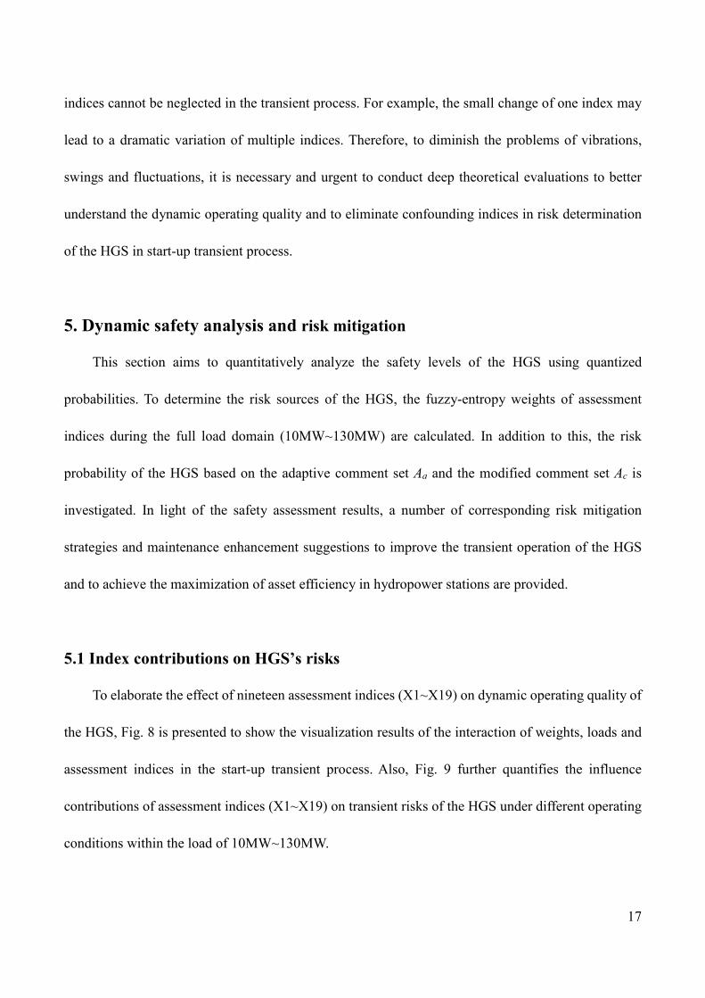
Transient safety assessment and risk mitigation strategy of a
hydroelectric generation system
Key Laboratory of Agricultural Soil and Water Engineering in Arid and Semiarid Areas, Ministry of
Education, Northwest A&F University, Shaanxi Yangling 712100, P. R. China
Lancaster University Renewable Energy Group and Fluid Machinery Group, Engineering Department,
Lancaster University, Lancaster UK
Corresponding author: Diyi Chen Telephone: 086-181-6198-0277 E-mail: [email protected]
Abstract: Transient safety assessment of hydroelectric generation systems is a major challenge for
engineers specializing in hydropower stations worldwide. This includes two key scientific issues: the
dynamic risk quantification in multi-factors coupling process, and the indices identification with high
contributions on system stability. This paper presents a new flexible, rapid and affordable dynamic
safety assessment methodology for a hydroelectric generation system. Based on the fuzzy-entropy
comprehensive evaluation method, the dynamic safety level of the system is estimated by means of
probability and the influence contributions of assessment indices on risk operations of the hydroelectric
generation system are also obtained. Moreover, some risk mitigation and maintenance strategies are
finally discussed to reduce dual losses of operation and maintenance in hydropower stations. The
methodology is implemented and validated in an existing hydropower station aiming at a start-up
transient process, which is beneficial to risk warning and maintenance strategy enhancement. In
addition the presented methodology in this paper is not only applied in the start-up transient process
2
but is also promisingly and appropriate for other large fluctuation transient processes.
Keywords: hydroelectric generation system; dynamic safety assessment; transient analysis; risk
mitigation; maintenance strategy
1. Introduction
The world energy industry is confronted with dual pressure of economic growth and
environmental protection, which drives the transformation of renewable energy development [1-3].
Hydropower, as a clear energy, is becoming of interest globally by governments and society due to its
reliability, flexibility and affordable expenses [4-7]. A 2017 Energy Report estimates that the world
average hydroelectric generation reached 3930 kilowatt hours, currently supplying 16% of world total
electricity and 68% of renewable electricity capacity [8]. The 2018 IHA Report highlights the
importance of hydropower in electricity generation, and its worldwide distribution and potential
development are shown in Fig. 1 [9]. The International Renewable Energy Agency (IRENA) predicts
that the world hydropower capacity will reach 2200 gigawatts by 2030 [10]. Thus, hydropower shows
a great potential and thus it is of a significant importance and interest to solve the problem of the energy
shortage.

3
203
783
167
716
249
599144
456468
1501
Technical potential assuming maximum generation
Estimated generation in 2017, in TWh per year
Installed capacity in 2017 in GW Hydropower's contribution: 1267 GW worldwide including 153 GW of pumped hydro
Worldwide Hydropower Distributions and Development
Fig. 1 Worldwide hydropower distributions and potential development [9].
Hydroelectric generation system (HGS) is a hydraulic, mechanical and electrical coupling facility,
which is composed of generating unit, penstock system and governing device [11-14]. Under the
influence of load disturbances, the HGS faces frequent dynamic state transitions (also called transient
processes) with the increase of large capacity generating unit [15-19]. This causes different degrees of
components’ faults such as piping breaking and abnormal swing of rotor [20-24]. In practice there is
an enormous challenge for efficient operation, fault prevention and maintenance forecast in
hydropower stations [25-28]. Hence, it is an urgent and important task to assess the dynamic safety of
HGSs. To date, some research scholars have attempted to study the HGS’s safety from the perspective
of independent subsystems like hydraulic subsystem, mechanical subsystem and electrical subsystem,
whereas such an approach ignores the nonlinear coupling between subsystems. Additionally, the
current method is based on the static HGS, which cannot accurately quantify the dynamic risks of
HGSs.
Fuzzy comprehensive evaluation method (FCE) and dynamic entropy-weight method herein are
4
developed to assess the transient safety of HGSs. FCE is a powerful condition assessment method by
means of the theory of fuzzy mathematics, which gives a global evaluation of uncertain system with
multiple internal-external factors [29-31]. The entropy-weight method is used to measure the degree
of indices’ variations, which has been widely applied in various research fields. In this paper, an
enhanced dynamic entropy-weight method is proposed to implement the dynamic FCE [32-34]. The
dynamic FCE presented in this work realizes the dual estimations of indices’ dynamic contributions
on system stability and the dynamic safety level during the transient process.
The target of this paper is assessing the transient safety of nonlinear HGSs and its innovation
could be summarized in three main points. First, a novel enhanced dynamic fuzzy-entropy evaluation
method, combining FCE with dynamic entropy-weight method, is presented to enable the transient
safety assessment. It could be stated that the dynamic FCE presented in this work can not only
implement the safety assessment of HGSs, but also be applied in other nonlinear complex systems.
Second, from the point of view of the entire system, this paper establishes a new safety assessment
framework of a hydraulic-mechanical-electrical coupling HGS. This framework aims at the large
fluctuation transient processes, such as start-up, shut-down and load rejection, which also realizes the
transition from static to dynamic assessment. Third, this paper seeks to provide some corresponding
risk mitigation strategies and maintenance enhancement suggestions to improve greatly the dynamic
stability of HGS as well as to reduce the operation loss and maintenance loss in hydropower stations.
2. Transient characteristics of hydroelectric generation system
The hydroelectric generation system (HGS) efficiently uses the hydropower to generate electricity
and transmits the electricity to power grid, thus it is very important to ensure and evaluate its safety
5
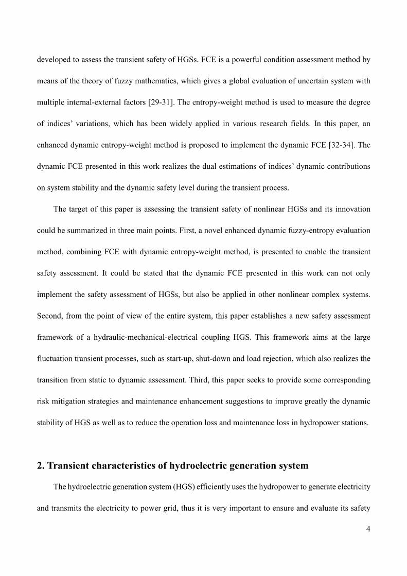
and operation in steady states and especially in transient processes. A universal HGS is composed of
reservoir, piping system, surge tank, hydro-turbine, generator and control system, as shown in Fig. 2.
Turbine
Head Water Surge Tank
Tail WaterPenstock L1 Penstock L2
Penstock L3
Power Grid
ControlCenter
interaction
Hydroelectric Generation Unit
Fig. 2 A structure of a hydroelectric generation system.
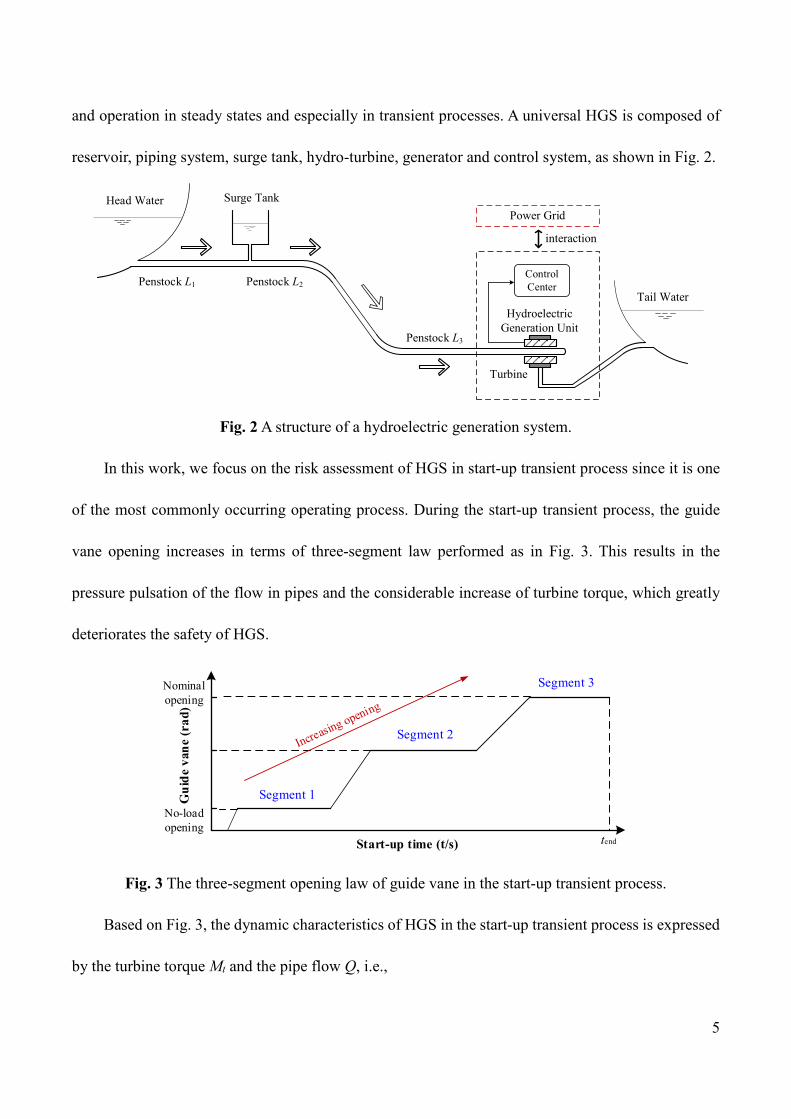
In this work, we focus on the risk assessment of HGS in start-up transient process since it is one
of the most commonly occurring operating process. During the start-up transient process, the guide
vane opening increases in terms of three-segment law performed as in Fig. 3. This results in the
pressure pulsation of the flow in pipes and the considerable increase of turbine torque, which greatly
deteriorates the safety of HGS.
Start-up time (t/s)
Gui
de v
ane
(rad
)
No-load opening
Nominal opening
Segment 1
Segment 2
Segment 3
tend
Fig. 3 The three-segment opening law of guide vane in the start-up transient process.
Based on Fig. 3, the dynamic characteristics of HGS in the start-up transient process is expressed
by the turbine torque Mt and the pipe flow Q, i.e.,

6
( , , )( , , )
t tM M H n yQ Q H n y
= =
, (1)
where H , n and y denote the hydro-turbine head, the hydro-turbine speed and the guide vane
opening, respectively.
In light of ref. [19], Eq. (1) can be further obtained as:
20
00
200 0
9.8
2
2
t
tt
HrQ ctgctg r
b F
ctgctgM Q r Q rb F
ηωω
βαπ
βα ωπ
+=
+
= + −
, (2)
where ω , α , tb , F , 0r and 0β denote the generator rotor speed, the guide vane discharge angle,
the guide vane height, the runner outlet area, the runner intermediate flow surface radius and the runner
intermediate flow surface angle, respectively.
3. Methodology
This paper presents an enhanced dynamic fuzzy-entropy evaluation method aiming at assessing
the HGS in large fluctuation transient process. This innovative method effectively overcomes the static
performance estimations in previous conventional approaches, and its implementation is conducive to
risk warning and maintenance schedule enhancement in hydropower stations.
To manage the shortcoming of subjective weights used in participation estimations of dynamic
assessment indices, a precise entropy weights method is employed. For a transient HGS, nineteen
assessment indices (X1~X19) and three comments of safety levels (Stable, Unstable and Unacceptable)
are extracted and their change rules are listed in Table 1. The stable comment means that the HGS is
in a normal working state within unavoidable vibrations and noises. The unstable comment is defined

7
as the relative harsh operating condition that is able to have negative impact on operators and the
residual operating life of HGS. The unacceptable comment refers to the immediate risk accident,
causing operation loss and maintenance loss in hydropower stations.
Table 1 Assessment principle for indices of the HGS
Comment level X1, X2, X3
X4, X5, X6, X7 X8, X9
X10, X11, X13, X14,
X19 X12, X15 X16 X17, X18
Stable (S) 0~54 0~280 0~350 0~100 0~70 0~35 0~80 Unstable (B) 74~108 320~460 400~525 120~200 90~140 45~70 100~160 Unacceptable (P) >108 >500 >575 >220 >160 >80 >180 Indices X1~X3 denote inlet pressure of spiral casing (kPa), pressure of head cover (kPa), and inlet pressure of draft pipe (kPa). Indices X4~X7 are swing of upper guide bearing in x-direction (μm), swing of upper guide bearing in y-direction (μm), swing of lower guide bearing in x-direction (μm), and swing of lower guide bearing in y-direction (μm). Indices X8~X9 are swing of hydraulic guide bearing in x-direction (μm), and swing of hydraulic guide bearing in y-direction (μm). Indices X10~X12 refer to vibration of upper bracket in x-direction (μm), vibration of upper bracket in y-direction (μm), and vibration of upper bracket in z-direction (μm). Indices X13~X16 represent vibration of lower bracket in x-direction (μm), vibration of lower bracket in y-direction (μm), vibration of lower bracket in z-direction (μm), and horizontal vibration of stator frame (μm). Indices X17~X19 are vibration of head cover in x-direction (μm), vibration of head cover in y-direction (μm), and vibration of head cover in z-direction (μm).
It is expected to mitigate vibrations, swings and pressure pulsation in actual operation of
hydropower station, thus all selected m assessment indices belong to the inverse index. If there are n
comments of safety levels, the normalization equation for the data of m assessment indices at transient
time t (t=[0, tend]) is expressed as:
max ( ) ( )( )
max ( ) min ( )ij ij
ijij ij
x t x tr t
x t x t−
=−
, i=1, 2, ..., m and j=1, 2, ..., n (3)
where ( )ijr t is the normalization set of inverse index at transient time t. max ( )ijx t and min ( )ijx t
denote the maximum and minimum values in allowing interval (see Table 1), respectively. ( )ijx t is
the actual data of assessment indices at transient time t.
Based on the entropy theory, then the entropy value of assessment index i at transient time t is
obtained as:
1( ) ( ) ln ( )n
i ij ijjH t r t r tλ
== ∑ , i=1, 2, ..., m (4)

8
where the variable 1ln n
λ = − .
If the normalized index ( )ijr t =0, then it yields:
( ) ln ( ) 0ij ijr t r t = . (5)
As a result, the entropy weight set of m assessment indices at transient time t, i.e.
1 2( )={ ( ), ( ),..., ( )}mW t t t tω ω ω , is calculated by the following equation.
1
1
1 ( )( )( )
( )=1
ii m
iim
ii
H ttm H t
t
ω
ω=
=
− = −
∑∑
, iω ∈[0, 1]. (6)
To ensure that the assessment indices (X1~X19) meet U={u1, u2, …, um} and comments of safety
levels (Stable-S, Unstable-B and Unacceptable-P) satisfy V={v1, v2, …, vn}. Based on classifications
of indices and the related change rules in Table 1, the fuzzy membership function of nineteen
assessment indices is divided into two types, as shown in Fig. 4. The shape of fuzzy membership
function of indices (X1, X2) are similar to index X3, and that of indices (5~19) are similar to index
X4. That is, based on the maximum and minimum of indices (X1~X19) and their corresponding fuzzy
membership functions could be finally determined.
(a) Inlet pressure of draft pipe (Index X3) (b) Swing of upper guide bearing in x-direction (Index X4)
Fig. 4 Two types of examples of fuzzy membership functions for assessment indices of the HGS in
0 20 40 60 80 100 120 140
Inlet pressure of draft pipe X3 (kPa)
0
0.2
0.4
0.6
0.8
1
μ(X
3)
μ(μs) μ(μb) μ(μp)
0 100 200 300 400 500
Swing of upper guide bearing in x-direction X4 (μm)
0
0.2
0.4
0.6
0.8
1
μ(X
4)
μ(μp)μ(μb)μ(μs)

9
start-up transient process.
Based on Fig. 4, the fuzzy membership functions of inlet pressure of draft pipe (X3) and swing
of upper guide bearing in x-direction (X4) at transient time t are respectively obtained in Eq. (7) and
Eq. (8). Besides, the other fuzzy membership functions of assessment indices are performed in
Appendix 1.
X3:
1, ( ,74]( ) 74
0,
27 , [54,74)20 101, (74,108]
( ) ( )32 , (108, )
20 50,
0, ( ,108]27( ) , (108,128]
20 51,
ij k t
p ps
others
p p
pV b
p p
others
ppp p
others
µ µ
µ µ µ
µ µ
− + ∈ −∞ = − ∈ ∈= = − − ∈
∈ −∞ = − ∈
, (7)
X4:
1, , 280]
( ) 8, (280,320]40
0,
7, (280,320]401, (320,460]
( ) ( )25 , (460,500]
40 20,
0, ( , 460]23( ) , (460,500]
40 21,
ij k t
pps p
others
p p
pV b
p p
others
ppp p
others
µ µ
µ µ µ
µ µ
∈ ∞ = − + ∈ − ∈ ∈= = − + ∈
∈ −∞
= − ∈
(-
, (8)
where ( )sµ µ , ( )bµ µ and ( )pµ µ are the fuzzy membership functions with respect to Stable
10
comment, unstable comment and unacceptable comment, respectively.
Subsequently, the fuzzy relationship assessment matrix regarding nineteen indices and three
comments of safety levels at time t yields:
11 1 1 12 1 2 13 1 3
21 2 1 22 2 2 23 2 3
31 3 1 32 3 2 33 3 3
41 4 1 42 4 2 43 4 3_
17 _1 17 1 17 _ 2 17 2
18_1 18 1 18_ 2 18
( , ) ( , ) ( , )( , ) ( , ) ( , )( , ) ( , ) ( , )( , ) ( , ) ( , )( )... ...( , ) ( , )( , ) (
t t t
t t t
t t t
t t tt ij m n
t t
t
u v u v u vu v u v u vu v u v u vu v u v u vR
u v u vu v u
µ µ µµ µ µµ µ µµ µ µ
µ µ
µ µ
× =
17 _ 3 17 3
2 18_ 3 18 3 18 3
...( , )
, ) ( , )t
t t
u vv u v
µ
µ×
. (9)
Combining Eq. (6) and Eq. (9), the fuzzy-entropy comprehensive assessment matrix at time t is
expressed as:
3 18 _ 18 3 1 2 3( ) ( ) { , , }t t t ij t t tA W R A A A× ×= ⋅ = . (10)
According to maximum membership principle, the adaptive safety level of HGS at time t is
max|t tA = and meets the condition of max| max|t t t t tA A A= = ∈, . Thus, the adaptive comment set of safety
levels during the whole start-up transient process is finally calculated as:
max| 1 max| 2 max| 1 max|{ , ,..., , }end enda t t t t t tA A A A A= = = − == . (11)
However, considering both unacceptable comment and unstable comment threaten the safety operation
of the HGS, we define a modified comment set of safety levels Ac that comprehensively takes into
account the total probability of the unstable and unacceptable comments.
B P| 1 B P| 2 B P| 1 B P|{ , ,..., , }end endc t t t t t tA A A A A+ = + = + = − + == . (12)
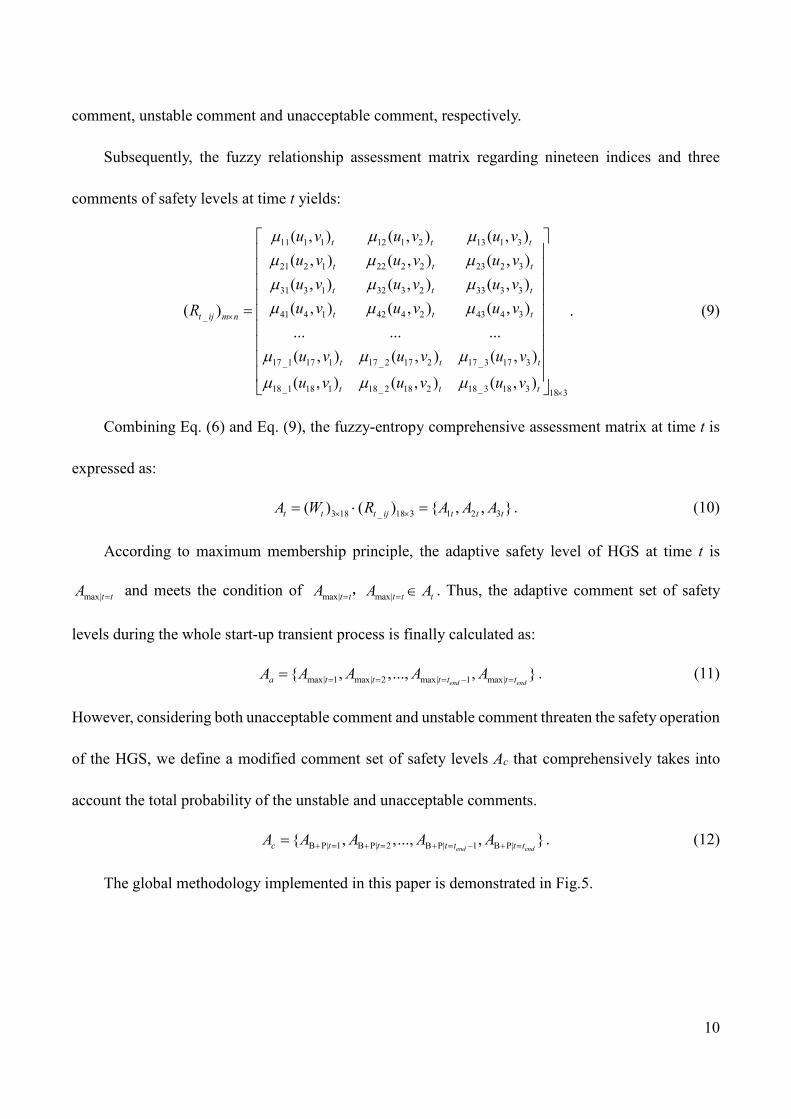
The global methodology implemented in this paper is demonstrated in Fig.5.
11
Transient characteristics analysis of hydroelectric generating system in start-up process
Dynamic balance experiment to obtain data information of assessment indices
Select transient data of assessment indices at time t, t=[0 s, tend s]
Determine assessment indices set U=(u1, u2, …, ui, …, um) and change rules of indices
Classify safety levels of assessment indices V=(v1, v2, …, vj, …, vn)
Create fuzzy membership matrixμ(U)
Establish fuzzy relationship assessment matrix Rt m×n
Normalization for all selected data of assessment indices at transient time t
Calculate entropy value of assessment index i
(i+1,… m)
Obtain entropy weight set of all assessment indices Wt=(ω1, ω2, …, ωi, ωm)
Calculate fuzzy-entropy comprehensive assessment matrix at time t, At=Rt m×n ·Wt=(A1t, A2t, …, Ajt, …, Ant)
time t=t+1
Maximum membership principle to select comment set of safety level from t=0 to t=tend, i.e. adaptive comment set Af =(Amax|t=1, Amax|t=2, …, Amax|t=tend )
Dynamic safety results visualization
Hydropower station achieves risk warning and amends maintenance schedule
START
END
Fuzzy Entropy
Calculate the modified comment set of safety levels Ac=(AB+P|t=1, AB+P|t=2, AB+P|t=tend)
Fig. 5 Global methodology of dynamic safety assessment of hydroelectric generating system.
The calculation process plan is concluded and described in the following steps:
(1) Carry out dynamic balance experiments on the basis of an existing hydropower station to
obtain the start-up transient data of HGS (i.e. indices X1~X19 listed in Table 1). To improve the data
reliability, use the analysis results of transient performance characteristics of the HGS to identify and
diminish outlier in data.
(2) Selecting thirteen monitoring times (t=t1~tend) referring to the transient time within increasing
loads 10MW, 20MW, 30MW and till 130MW to collect data signals of multiple sensors. According to

12
time priority, evaluate orderly the safety properties of HGS from time t1 to time tend.
(3) To enable the fuzzy-entropy analysis, first determine nineteen assessment indices (i.e.
X1~X19) and three comments of safety levels (i.e. Stable, Unstable and Unacceptable) defined
respectively as U={u1, u2, …, um} and V={v1, v2, …, vn}. In light of the change rules in Table 1, the
fuzzy membership function 1 ~( )
endt tVµ and fuzzy relationship assessment matrix 1 ~( )
endm n t tR × at
different times are respectively obtained as equations (7, 8) and equation (9).
(4) Calculating the entropy values of normalized assessment indices at the time interval t=[ t1,
tend], and subsequently deducing the corresponding entropy weight set ( )W t in light of equation (6).
(5) Creating the fuzzy-entropy comprehensive assessment matrices At1~Atend at different times
that can be defined by the product between fuzzy relationship assessment matrix 1 ~( )
endm n t tR × and
entropy weight set ( )W t . Using maximum membership principle to select the adaptive comment set
of safety levels max| 1 max| 2 max| 1 max|{ , ,..., , }end enda t t t t t tA A A A A= = = − == . Considering the dual threat of
unacceptable and unstable states of the HGS, We define a modified comment set of safety levels
B P| 1 B P| 2 B P| 1 B P|{ , ,..., , }end endc t t t t t tA A A A A+ = + = + = − + == . Finally, we visualize the transient safety assessment
results of the HGS.
(6) Based on the analysis results, provide some important risk mitigation strategies and
maintenance enhancement suggestions to improve greatly the dynamic safety of HGS and to reduce
the losses of operation and maintenance in hydropower stations.
4. Experiments
4.1 Start-up dynamic balance experiment
To obtain assessment data of the HGS in start-up transient process, dynamic balance experiments

13
are carried out based on an existing hydropower station in China. The mechanical-electric parameters
information [35] and hydraulic testing conditions are listed in Table 2.
Table 2 Hydraulic-mechanical-electric information of experimental HGS in start-up transient process
Mechanical-electric Parameters Information Hydro-turbine type HLS270-LJ-680 Nominal turbine power 267.85MW Nominal turbine head 64m Nominal turbine flow 460.46m3/s Nominal turbine speed 93.75rpm Runaway speed 185rpm Generator type SF265-64/15000 Generator capacity 291.7MVA Stator voltage 15750V Stator current 10692A Generator power factor 0.9 Exciting voltage 350V Exciting current 1900A Nominal frequency 50Hz
Governor type PFWT-200-6.3 Main configuration diameter
200mm
Operating oil pressure 6.3MPa Servomotor stroke 780mm Lower guide bearing clearance
0.15~0.2mm Upper guide bearing clearance
0.15~0.2mm
Water guide bearing clearance
0.2~0.25mm Cylinder diameter of servomotor
640mm
Hydraulic Testing Conditions Upstream water level 431.93m Downstream water level 367.19m Opening range of guide vane
18.5%~50.2% Maximum active power in start-up transient
130MW
Actual station head 64.74m
The monitoring targets in the dynamic balance experiment are the indices X1~X19 listed in Table
1. The start-up experimental data are adopted from thirteen transient calculated conditions that refer to
the transient times within the corresponding increasing active load of 10MW, 20MW, 30MW, 40MW,
50MW, 60MW, 70MW, 80MW, 90MW, 100MW, 110MW, 120MW and 130MW. The experimental
mainframes include PSTA-H vibration instrumentation and TTS216 dynamic signal instrumentation.
The key phase patch is attached to the main shaft of generator. Electric eddy-current displacement
sensors measure the swing of upper guide bearing in x/y-direction (X4 and X5), the swing of lower
guide bearing in x/y-direction (X6 and X7) and the swing of hydraulic guide bearing in x/y-direction

14
(X8 and X9). Low-frequency shock transducers are used to monitor the horizontal/vertical vibrations
of upper bracket, lower bracket, stator frame and head cover (i.e., X10~X19). Water pressure
transducers measure the inlet pressure of spiral casing (X1), the pressure of head cover (X2) and the
Inlet pressure of draft pipe (X3). Finally, all monitoring data of assessment indices are transmitted and
analyzed by experimental mainframes. the measured vibrations and swings (X4~X19) belong to peak-
to-peak values. The obtained inlet pressure of spiral casing (X1) is the mean value, and the
experimental pressure of head cover (X2) and the inlet pressure of draft pipe (X3) are peak-to-peak
values.
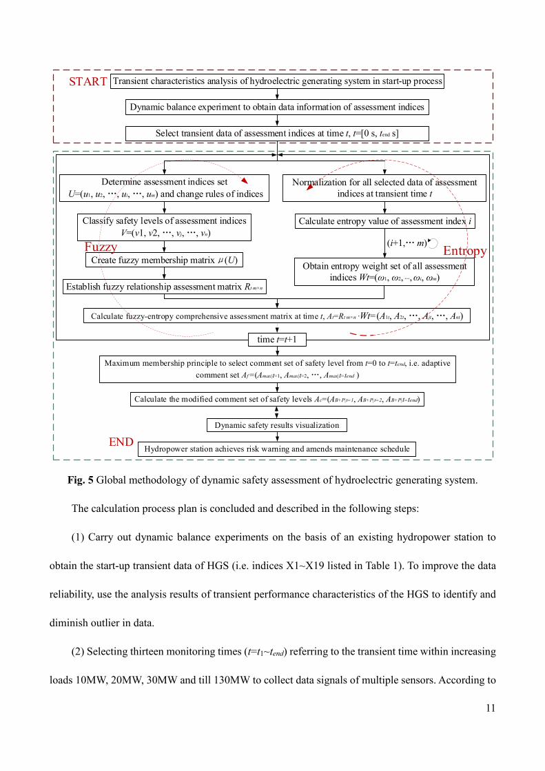
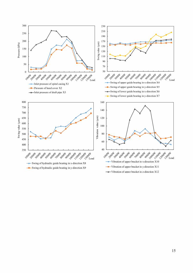
The layout of supervision points in the dynamic balance experiment is performed in Fig. 6, and
the monitoring data are shown in Fig. 7.
Horizontal swing of guide bearing
Horizontal and vertical vibration of upper bracket
Horizontal and vertical vibration of lower bracket
Horizontal and vertical vibration of head cover
Inlet pressure pulsation of draft pipe
Inlet pressure of spiral casing
Horizontal vibration of stator frame
Fig. 6 Layout of supervision points of the HGS for the start-up transient process in dynamic balance
experiment.
15
0
50
100
150
200
250
300
Inlet pressure of spiral casing X1Pressure of head cover X2Inlet pressure of draft pipe X3
Load
Pres
sure
(kPa
)
50
70
90
110
130
150
170
190
210
230
Swing of upper guide bearing in x-direction X4
Swing of upper guide bearing in y-direction X5
Swing of lower guide bearing in x-direction X6
Swing of lower guide bearing in y-direction X7Sw
ing
valu
e (μ
m)
Load
350
400
450
500
550
600
650
700
750
800
Swing of hydraulic guide bearing in x-direction X8
Swing of hydraulic guide bearing in y-direction X9
Swin
gva
lue
(μm
)
Load
40
60
80
100
120
140
160
Vibration of upper bracket in x-direction X10
Vibration of upper bracket in y-direction X11
Vibration of upper bracket in z-direction X12
Vib
ratio
n va
lue
( μm
)
Load
16
0
50
100
150
200
250
300
350
400
450
Vibration of lower bracket in x-direction X13
Vibration of lower bracket in y-direction X14
Vibration of lower bracket in z-direction X15
Horizontal vibration of stator frame X16
Vibr
atio
n va
lue
(μm
)
Load
0
100
200
300
400
500
600
Vibration of head cover in x-direction X17
Vibration of head cover in y-direction X18
Vibration of head cover in z-direction X19Vi
brat
ion
valu
e (μ
m)
Load
Fig. 7 Experiment data of nineteen assessment indices (X1~X19) of the HGS in start-up transient
process.
4.2 Preliminary experimental analysis
From the experimental results in Fig. 7, it is observed that some indices exceed the allowable
operating ranges (as listed in ref. [35]). Specifically, the peak values of swing of hydraulic guide
bearing in x-direction (X8) and swing of hydraulic guide bearing in y-direction (X9) are roughly
710μm and 653μm, respectively. This is almost more than double compared to the allowable operating
value of 300μm. The measured inlet pressure of draft pipe (X3) reaches the maximum of 269.5kPa,
which is obviously greater than the allowable operating value of 64kPa. Additionally, the instability
problems also exist in the inlet pressure of spiral casing (X1), the vibration of upper bracket in z-
direction (X12), the vibration of lower bracket in z-direction (X15), the vibration of head cover in
x/y/z-direction (X17, X18 and X19).
However, it is difficult to determine the location of risk sources since half of all indices exceed
their maximum allowable values. Besides, the complex internal coupling characteristics of different
17
indices cannot be neglected in the transient process. For example, the small change of one index may
lead to a dramatic variation of multiple indices. Therefore, to diminish the problems of vibrations,
swings and fluctuations, it is necessary and urgent to conduct deep theoretical evaluations to better
understand the dynamic operating quality and to eliminate confounding indices in risk determination
of the HGS in start-up transient process.
5. Dynamic safety analysis and risk mitigation
This section aims to quantitatively analyze the safety levels of the HGS using quantized
probabilities. To determine the risk sources of the HGS, the fuzzy-entropy weights of assessment
indices during the full load domain (10MW~130MW) are calculated. In addition to this, the risk
probability of the HGS based on the adaptive comment set Aa and the modified comment set Ac is
investigated. In light of the safety assessment results, a number of corresponding risk mitigation
strategies and maintenance enhancement suggestions to improve the transient operation of the HGS
and to achieve the maximization of asset efficiency in hydropower stations are provided.
5.1 Index contributions on HGS’s risks
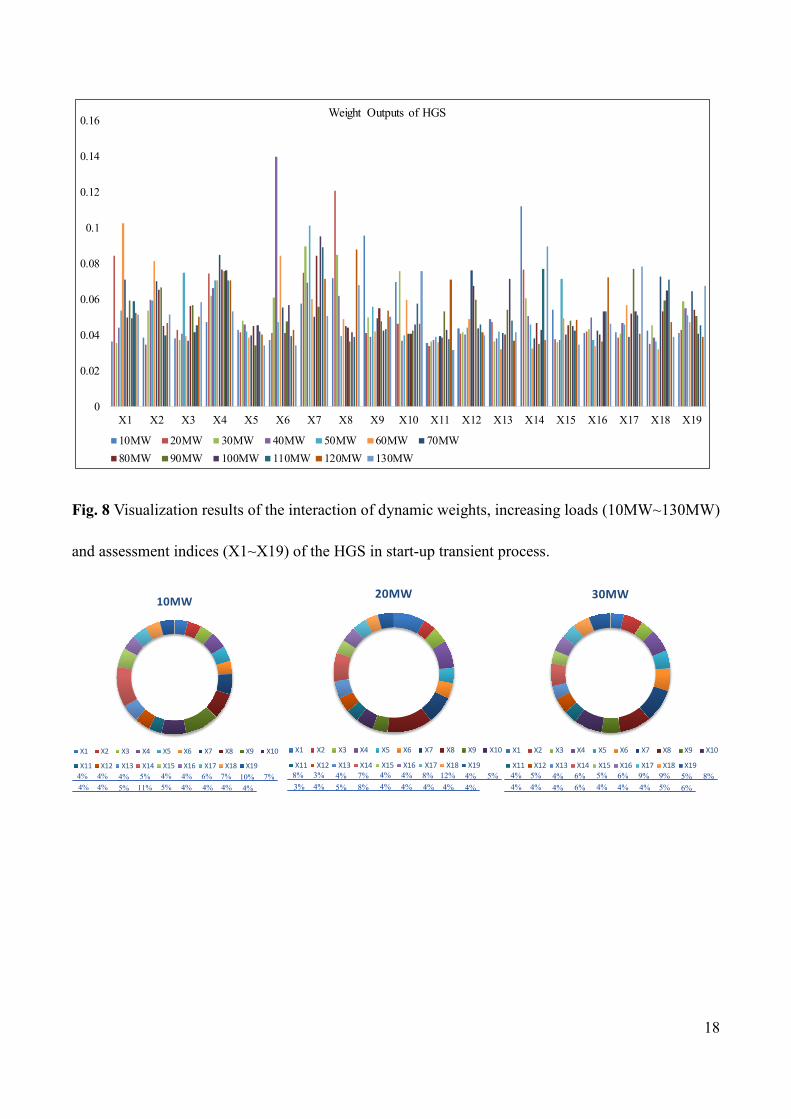
To elaborate the effect of nineteen assessment indices (X1~X19) on dynamic operating quality of
the HGS, Fig. 8 is presented to show the visualization results of the interaction of weights, loads and
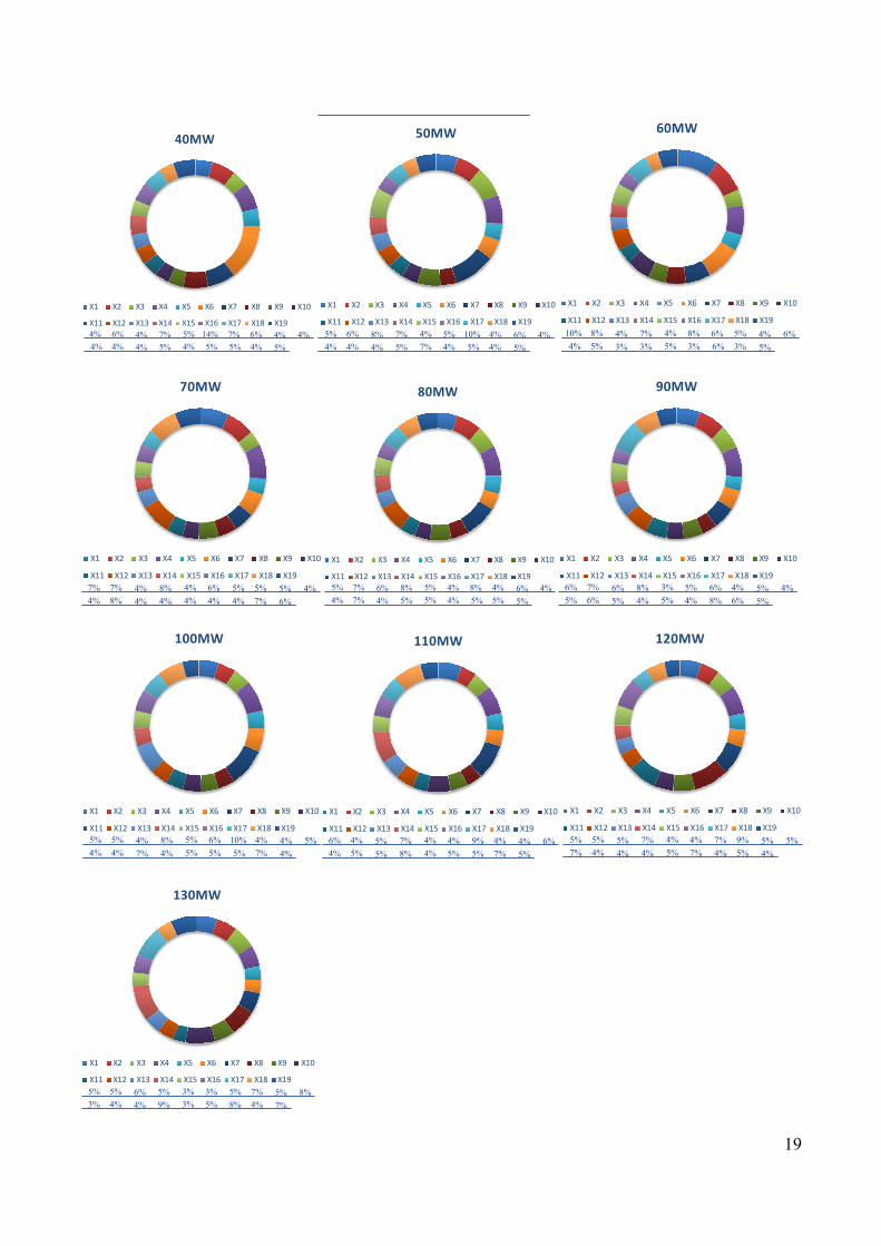
assessment indices in the start-up transient process. Also, Fig. 9 further quantifies the influence
contributions of assessment indices (X1~X19) on transient risks of the HGS under different operating
conditions within the load of 10MW~130MW.
18
0
0.02
0.04
0.06
0.08
0.1
0.12
0.14
0.16
X1 X2 X3 X4 X5 X6 X7 X8 X9 X10 X11 X12 X13 X14 X15 X16 X17 X18 X19
Weight Outputs of HGS
10MW 20MW 30MW 40MW 50MW 60MW 70MW80MW 90MW 100MW 110MW 120MW 130MW
Fig. 8 Visualization results of the interaction of dynamic weights, increasing loads (10MW~130MW)
and assessment indices (X1~X19) of the HGS in start-up transient process.
10MW
X1 X2 X3 X4 X5 X6 X7 X8 X9 X10
X11 X12 X13 X14 X15 X16 X17 X18 X194% 4% 4% 5% 4% 4% 6% 7% 10% 7%4% 4% 5% 11% 5% 4% 4% 4% 4%
20MW
X1 X2 X3 X4 X5 X6 X7 X8 X9 X10
X11 X12 X13 X14 X15 X16 X17 X18 X198% 3% 4% 7% 4% 4% 8% 12% 4% 5%3% 4% 5% 8% 4% 4% 4% 4% 4%
30MW
X1 X2 X3 X4 X5 X6 X7 X8 X9 X10
X11 X12 X13 X14 X15 X16 X17 X18 X194% 5% 4% 6% 5% 6% 9% 9% 5% 8%4% 4% 4% 6% 4% 4% 4% 5% 6%
19
40MW
X1 X2 X3 X4 X5 X6 X7 X8 X9 X10
X11 X12 X13 X14 X15 X16 X17 X18 X194% 6% 4% 7% 5% 14% 7% 6% 4% 4%4% 4% 4% 5% 4% 5% 5% 4% 5%
50MW
X1 X2 X3 X4 X5 X6 X7 X8 X9 X10
X11 X12 X13 X14 X15 X16 X17 X18 X195% 6% 8% 7% 4% 5% 10% 4% 6% 4%4% 4% 4% 5% 7% 4% 5% 4% 5%
60MW
X1 X2 X3 X4 X5 X6 X7 X8 X9 X10
X11 X12 X13 X14 X15 X16 X17 X18 X1910% 8% 4% 7% 4% 8% 6% 5% 4% 6%4% 5% 3% 3% 5% 3% 6% 3% 5%
70MW
X1 X2 X3 X4 X5 X6 X7 X8 X9 X10
X11 X12 X13 X14 X15 X16 X17 X18 X197% 7% 4% 8% 4% 6% 5% 5% 5% 4%4% 8% 4% 4% 4% 4% 4% 7% 6%
80MW
X1 X2 X3 X4 X5 X6 X7 X8 X9 X10
X11 X12 X13 X14 X15 X16 X17 X18 X195% 7% 6% 8% 5% 4% 8% 4% 6% 4%4% 7% 4% 5% 5% 4% 5% 5% 5%
90MW
X1 X2 X3 X4 X5 X6 X7 X8 X9 X10
X11 X12 X13 X14 X15 X16 X17 X18 X196% 7% 6% 8% 3% 5% 6% 4% 5% 4%5% 6% 5% 4% 5% 4% 8% 6% 5%
100MW
X1 X2 X3 X4 X5 X6 X7 X8 X9 X10
X11 X12 X13 X14 X15 X16 X17 X18 X195% 5% 4% 8% 5% 6% 10% 4% 4% 5%4% 4% 7% 4% 5% 5% 5% 7% 4%
110MW
X1 X2 X3 X4 X5 X6 X7 X8 X9 X10
X11 X12 X13 X14 X15 X16 X17 X18 X196% 4% 5% 7% 4% 4% 9% 4% 4% 6%4% 5% 5% 8% 4% 5% 5% 7% 5%
120MW
X1 X2 X3 X4 X5 X6 X7 X8 X9 X10
X11 X12 X13 X14 X15 X16 X17 X18 X195% 5% 5% 7% 4% 4% 7% 9% 5% 5%7% 4% 4% 4% 5% 7% 4% 5% 4%
130MW
X1 X2 X3 X4 X5 X6 X7 X8 X9 X10
X11 X12 X13 X14 X15 X16 X17 X18 X195% 5% 6% 5% 3% 3% 5% 7% 5% 8%3% 4% 4% 9% 3% 5% 8% 4% 7%

20
Fig. 9 Quantified results of contribution weights of nineteen assessment indices (X1~X19) on HGS’s
risks for the start-up transient process under different operating conditions within the increasing load
of 10MW, 20MW, 30MW, 40MW, 50MW, 60MW, 70MW, 80MW, 90MW, 100MW, 110MW, 120MW
and 130MW.
From Fig. 8 and Fig. 9, there are different influence weights of the same index during the full load
domain (10MW~130MW), implying that the indices have uncertain risk contributions on the transient
HGS. for example, the time-varying weights set of index X1 is [0.0367, 0.0846, 0.0357, 0.0443, 0.0537,
0.1027, 0.0712, 0.05, 0.0595, 0.0494, 0.0589, 0.0526, 0.0518] with respect to the increasing load from
10MW to 130MW. Moreover, for the same load condition, the indices X1~X19 develops within the
mutual effect and restriction as the system load continuously increases. This means that almost all
indices have a high sensibility to the risk contribution of leading indices at different dynamic risk
evolution stages. Additionally, it is easy to find that the critical indices with prominent high risk
contributions roughly include the inlet pressure of spiral casing (X1), swing of lower guide bearing in
x-direction (X6), swing of lower guide bearing in y-direction (X7), swing of hydraulic guide bearing
in x-direction (X8), swing of hydraulic guide bearing in y-direction (X9) and vibration of lower bracket
in y-direction (X14).
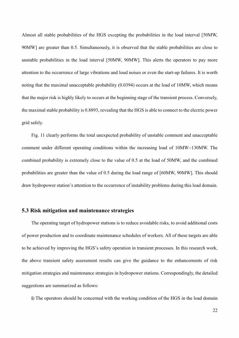
5.2 Transient safety assessment of HGS
Based on equation (11), Fig. 10 presents the adaptive comment set of HGS’s safety levels (i.e. Aa)
to reflect the probabilities of stable, unstable and unacceptable operating states in the start-up transient
process. Based on equation (12), the modified comment set (i.e. Ac) is shown in Fig. 11 to reveal the
dual adverse effect of the unstable state and unacceptable state on the transient HGS.

21
Fig. 10 Dynamic safety levels of the HGS obtained from the adaptive comment set Aa in the start-up
transient process.
0
0.5
Membership Ratio of HGS
Unacceptable Unstable Stable
Load
1
Probability
Fig. 11 Enhanced dynamic safety levels of the HGS obtained from the modified comment set Ac in the
start-up transient process.
As shown in Fig. 10, all final adaptive comments for safety levels of the transient HGS under
different load conditions are judged to be stable on the basis of the maximum membership principle.
10 20 30 40 50 60 70 80 90 100 110 120 130
Increasing load (MW)
0
0.1
0.2
0.3
0.4
0.5
0.6
0.7
0.8
0.9
Safe
ty m
embe
rshi
p of
HG
S
Stable
Unstable
Unacceptable
Probability=0.5
Probability<0.5
22
Almost all stable probabilities of the HGS excepting the probabilities in the load interval [50MW,
90MW] are greater than 0.5. Simultaneously, it is observed that the stable probabilities are close to
unstable probabilities in the load interval [50MW, 90MW]. This alerts the operators to pay more
attention to the occurrence of large vibrations and loud noises or even the start-up failures. It is worth
noting that the maximal unacceptable probability (0.0394) occurs at the load of 10MW, which means
that the major risk is highly likely to occurs at the beginning stage of the transient process. Conversely,
the maximal stable probability is 0.8893, revealing that the HGS is able to connect to the electric power
grid safely.
Fig. 11 clearly performs the total unexpected probability of unstable comment and unacceptable
comment under different operating conditions within the increasing load of 10MW~130MW. The
combined probability is extremely close to the value of 0.5 at the load of 50MW, and the combined
probabilities are greater than the value of 0.5 during the load range of [60MW, 90MW]. This should
draw hydropower station’s attention to the occurrence of instability problems during this load domain.
5.3 Risk mitigation and maintenance strategies
The operating target of hydropower stations is to reduce avoidable risks, to avoid additional costs
of power production and to coordinate maintenance schedules of workers. All of these targets are able
to be achieved by improving the HGS’s safety operation in transient processes. In this research work,
the above transient safety assessment results can give the guidance to the enhancements of risk
mitigation strategies and maintenance strategies in hydropower stations. Correspondingly, the detailed
suggestions are summarized as follows:
i) The operators should be concerned with the working condition of the HGS in the load domain
23
[50MW, 90MW], monitoring timely risk indices to generate effective warning strategies to avoid
failure accidents. The hydropower station develops urgent maintenance procedures to realize the goal
of loss-aversion. Meanwhile, it is better for maintenance workers to pay more attention to the faults
location during the next maintenance period if the warning strategies and maintenance procedures are
entirely ineffective.
ii) Aiming at the situation that the high risk occurs at the early stage of the start-up transient
process, it is suggested that the operating planners optimize the start-up strategy such as the
optimization of guide vane law and the reduction of misoperation frequency. Additionally, the
hydropower station should arrange repair plans to manage with potential adverse accidents.
iii) The final assessment comment of the HGS’s dynamic operating quality is stable, although we
cannot exclude the occurrence of potential unstable and unacceptable events. Based on this comment,
the hydropower is able to extend the maintenance period or change its regular time-based maintenance
strategy to condition-based maintenance strategy to optimize the maintenance schedule of workers and
to minimize the maintenance loss.
6. Conclusions
This paper evaluates the transient safety quality of the HGS, providing contributions to the current
international pool of dynamic safety knowledge compared with the conventional static safety
assessment of HGSs. To achieve the analysis, it first develops an enhanced fuzzy-entropy evaluation
approach to enable the dynamic risk quantification based on the assessment indices obtained by
dynamic balance experiments and corresponding theory modifications. The calculated dynamic
weights of indices reveal their influence contributions on instability of the HGS. Then finds that the

24
critical indices with prominent high risk contributions for the start-up transient process roughly include
the inlet pressure of spiral casing (X1), swing of lower guide bearing in x-direction (X6), swing of
lower guide bearing in y-direction (X7), swing of hydraulic guide bearing in x-direction (X8), swing
of hydraulic guide bearing in y-direction (X9) and vibration of lower bracket in y-direction (X14).
Additionally, the transient safety levels for the full load domain (10MW, 130MW) are successfully
estimated, and the assessment results show that the final evaluation comment of safety quality for the
start-up transient HGS is stable, although it cannot be excluded the potential unstable and unacceptable
events. The hydropower stations will pay more attention to operating states of the HGS in the load
interval [50MW, 90MW] since the stable probabilities are close to unstable probabilities.
Simultaneously, the dynamic safety status at the early stage of the transient process is also required to
pay special attention because the relevant maximal unacceptable probability reaches 0.0394. Finally,
aiming at the results of the quantitative calculation and qualitative analysis, it presents some
corresponding responses of risk mitigation strategies and maintenance amending suggestions to
improve greatly the transient safety quality of HGS, to reduce the loss of power production and to
optimize maintenance schedules of workers in hydropower stations. Our future work will focus on the
application of the proposed methodology in the safety assessment of other large fluctuation transient
processes (e.g. load rejection, generating phase modulation and operation switching between different
transient processes).
Acknowledgments
This work was supported by the scientific research foundation of National Natural Science
Foundation of China--Outstanding Youth Foundation (51622906), National Natural Science

25
Foundation of China (51479173), Fundamental Research Funds for the Central Universities
(201304030577), Scientific research funds of Northwest A&F University (2013BSJJ095), Science
Fund for Excellent Young Scholars from Northwest A&F University (Z109021515) and Shaanxi Nova
program (2016KJXX-55).
Appendix 1
Fuzzy membership functions of nineteen assessment indices (i.e. X1~x19) are calculated as:
(X1~X3):
1, ( ,74]( ) 74
0,
27 , [54,74)20 101, (74,108]
( ) ( )32 , (108, )
20 50,
0, ( ,108]27( ) , (108,128]
20 51,
ij k t
p ps
others
p p
pV b
p p
others
ppp p
others
µ µ
µ µ µ
µ µ
− + ∈ −∞ = − ∈ ∈= = − − ∈
∈ −∞ = − ∈
, (13)
26
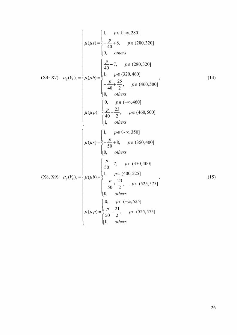
(X4~X7):
1, , 280]
( ) 8, (280,320]40
0,
7, (280,320]401, (320,460]
( ) ( )25 , (460,500]
40 20,
0, ( , 460]23( ) , (460,500]
40 21,
ij k t
pps p
others
p p
pV b
p p
others
ppp p
others
µ µ
µ µ µ
µ µ
∈ ∞ = − + ∈ − ∈ ∈= = − + ∈
∈ −∞
= − ∈
(-
, (14)
(X8, X9):
1, ,350]
( ) 8, (350,400]50
0,
7, (350,400]501, (400,525]
( ) ( )23 , (525,575]
50 20,
0, ( ,525]21( ) , (525,575]
50 21,
ij k t
pps p
others
p p
pV b
p p
others
ppp p
others
µ µ
µ µ µ
µ µ
∈ ∞ = − + ∈ − ∈ ∈= = − + ∈
∈ −∞
= − ∈
(-
, (15)

27
(X10, X11, X13, X14, X19):
1, ,100]
( ) 6, (100,120]20
0,
5, (100,120]201, (120,200]
( ) ( )11, (200,220]
200,
0, ( , 200]
( ) 10, (200,220]201,
ij k t
pps p
others
p p
pV b
p p
others
ppp p
others
µ µ
µ µ µ
µ µ
∈ ∞ = − + ∈ − ∈ ∈= = − + ∈
∈ −∞
= − ∈
(-
, (16)
(X12, X15):
1, ,70]9( ) , (70,90]
20 20,
7 , (70,90]20 21, (90,140]
( ) ( )8, (140,160]
200,
0, ( ,140]
( ) 7, (140,160]201,
ij k t
pps p
others
p p
pV b
p p
others
ppp p
others
µ µ
µ µ µ
µ µ
∈ ∞ = − + ∈ − ∈ ∈= = − + ∈
∈ −∞ = − ∈
(-
, (17)
28
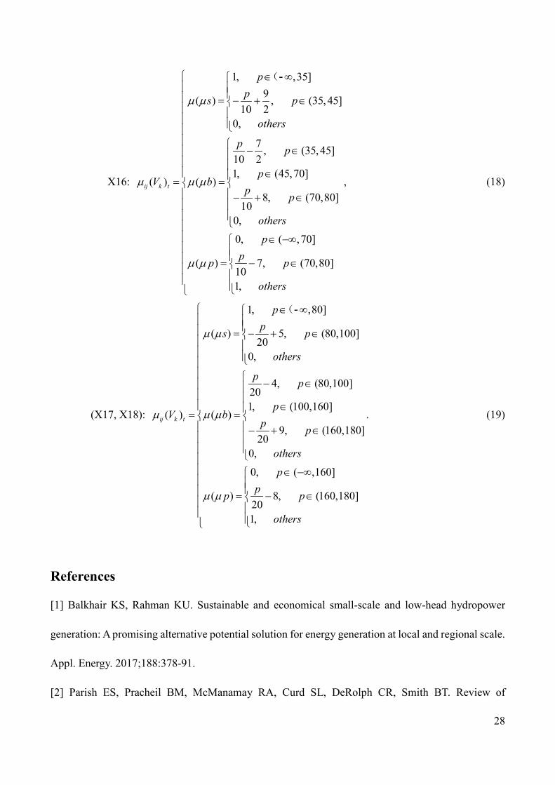
X16:
1, ,35]9( ) , (35,45]
10 20,
7 , (35,45]10 21, (45,70]
( ) ( )8, (70,80]
100,
0, ( ,70]
( ) 7, (70,80]101,
ij k t
pps p
others
p p
pV b
p p
others
ppp p
others
µ µ
µ µ µ
µ µ
∈ ∞ = − + ∈ − ∈ ∈= = − + ∈
∈ −∞ = − ∈
(-
, (18)
(X17, X18):
1, ,80]
( ) 5, (80,100]20
0,
4, (80,100]201, (100,160]
( ) ( )9, (160,180]
200,
0, ( ,160]
( ) 8, (160,180]201,
ij k t
pps p
others
p p
pV b
p p
others
ppp p
others
µ µ
µ µ µ
µ µ
∈ ∞ = − + ∈ − ∈ ∈= = − + ∈
∈ −∞ = − ∈
(-
. (19)
References
[1] Balkhair KS, Rahman KU. Sustainable and economical small-scale and low-head hydropower
generation: A promising alternative potential solution for energy generation at local and regional scale.
Appl. Energy. 2017;188:378-91.
[2] Parish ES, Pracheil BM, McManamay RA, Curd SL, DeRolph CR, Smith BT. Review of

29
environmental metrics used across multiple sectors and geographies to evaluate the effects of
hydropower development. Appl. Energy. 2019;238:101-18.
[3] Nicotra A, Zema DA, D'Agostino D, Zimbone SM. Equivalent Small Hydro Power: A Simple
Method to Evaluate Energy Production by Small Turbines in Collective Irrigation Systems. Water.
2018;10(10).
[4] Nash S, Phoenix A. A review of the current understanding of the hydro-environmental impacts of
energy removal by tidal turbines. Renew. Sust. Energ. Rev. 2017;80:648-62.
[5] Ptak T. Towards an ethnography of small hydropower in China: Rural electrification,
socioeconomic development and furtive hydroscapes. Energy Res. Soc. Sci. 2019;48:116-30.
[6] Tarroja B, Forrest K, Chiang F, AghaKouchak A, Samuelsen S. Implications of hydropower
variability from climate change for a future, highly-renewable electric grid in California. Appl. Energy.
2019;237:353-66.
[7] Semmari H, Mauran S, Stitou D. Experimental validation of an analytical model of hydraulic motor
operating under variable electrical loads and pressure heads. Appl. Energy. 2017;206:1309-20.
[8] Riasi A, Tazraei P. Numerical analysis of the hydraulic transient response in the presence of surge
tanks and relief valves. Renew. Energy. 2017;107:138-46.
[9] IHA international hydropower association. 2018 Hydropower status report (Fifth Edition). Launced
24 May 2018. http://hydropower.org/status2018
[10] International Energy Agency, Energy Balances of OECD Countries (2013 Preliminary Edition),
and Energy Balances of Non-OECD Countries, October 2012.
[11] Wen X, Zhou J, He Z, Wang C. Long-Term Scheduling of Large-Scale Cascade Hydropower
Stations Using Improved Differential Evolution Algorithm. Water. 2018;10(4).

30
[12] Xu B, Chen D, Zhang X, Alireza R. Parametric uncertainty in affecting transient characteristics
of multi-parallel hydropower systems in the successive load rejection. Int. J. Electr. Power Energy Syst.
2019;106:444-54.
[13] Xu B, Jun H-B, Chen D, Li H, Zhang J, Cavalcante Blanco CJ, et al. Stability analysis of a hydro-
turbine governing system considering inner energy losses. Renew. Energy. 2019;134:258-66.
[14] Yan D, Zhuang K, Xu B, Chen D, Mei R, Wu C, et al. Excitation Current Analysis of a
Hydropower Station Model Considering Complex Water Diversion Pipes. J Energ. Eng.-ASCE.
2017;143(5).
[15] Guo W. Nonlinear Disturbance Decoupling Control for Hydro-Turbine Governing System with
Sloping Ceiling Tailrace Tunnel Based on Differential Geometry Theory. Energies. 2018;11(12).
[16] Guo W, Yang J. Hopf bifurcation control of hydro-turbine governing system with sloping ceiling
tailrace tunnel using nonlinear state feedback. Chaos Solitons Fractals. 2017;104:426-34.
[17] Guo W, Yang J. Stability performance for primary frequency regulation of hydro-turbine
governing system with surge tank. Appl. Math. Model. 2018;54:446-66.
[18] Li H, Chen D, Arzaghi E, Abbassi R, Xu B, Patelli E, et al. Safety assessment of hydro -generating
units using experiments and grey-entropy correlation analysis. Energy. 2018;165:222-34.
[19] Li H, Chen D, Zhang X, Wu Y. Dynamic analysis and modelling of a Francis hydro-energy
generation system in the load rejection transient. IET Renew. Power Gener. 2016;10(8):1140-8.
[20] Horynova M, Klakurkova L, Svejcar J, Julis M, Gejdos P, Celko L. Failure analysis of casing of
draft tube of turbine used in hydropower plant. Eng. Fail. Anal.. 2017;82:848-54.
[21] Kramer M, Wieprecht S, Terheiden K. Minimising the air demand of micro-hydro impulse
turbines in counter pressure operation. Energy. 2017;133:1027-34.

31
[22] Li H-b, Yang X-g, Zhang X-b, Zhou J-w. Deformation and failure analyses of large underground
caverns during construction of the Houziyan Hydropower Station, Southwest China. Eng. Fail. Anal.
2017;80:164-85.
[23] Ma J, Wang Y, Feng X. Energy recovery in cooling water system by hydro turbines. Energy.
2017;139:329-40.
[24] Ming B, Liu P, Guo S, Zhang X, Feng M, Wang X. Optimizing utility-scale photovoltaic power
generation for integration into a hydropower reservoir by incorporating long- and short-term
operational decisions. Appl. Energy. 2017;204:432-45.
[25] Adhikari RC, Wood DH. A new nozzle design methodology for high efficiency crossflow hydro
turbines. Energy Sustain Dev. 2017;41:139-48.
[26] Adhikari RC, Wood DH. Computational analysis of part-load flow control for crossflow hydro-
turbines. Energy Sustain Dev. 2018;45:38-45.
[27] Dong H, Ye F, Fu W. Stability reliability of a cutting slope in Laohuzui Hydropower Station in
Tibet of China. Geomat. Nat. Hazards Risk. 2019;10(1):935-57.
[28] Silva PASF, Rio Vaz DATD, Britto V, de Oliveira TF, Vaz JRP, Brasil Junior ACP. A new approach
for the design of diffuser-augmented hydro turbines using the blade element momentum. Energy Conv.
Manag. 2018;165:801-14.
[29] Hu J, Chen J, Chen Z, Cao J, Wang Q, Zhao L, et al. Risk assessment of seismic hazards in
hydraulic fracturing areas based on fuzzy comprehensive evaluation and AHP method (FAHP): A case
analysis of Shangluo area in Yibin City, Sichuan Province, China. J. Pet. Sci. Eng. 2018;170:797-812.
[30] Shan W, Cai S, Liu C. A New Comprehensive Evaluation Method for Water Quality: Improved
Fuzzy Support Vector Machine. Water. 2018;10(10).
32
[31] Yang W, Xu K, Lian J, Bin L, Ma C. Multiple flood vulnerability assessment approach based on
fuzzy comprehensive evaluation method and coordinated development degree model. J Environ.
Manage. 2018;213:440-50.
[32] Li H, Sun J, Ma H, Tian Z, Li Y. A novel method based upon modified composite spectrum and
relative entropy for degradation feature extraction of hydraulic pump. Mech. Syst. Signal Proc.
2019;114:399-412.
[33] Liu P, Zheng N, Liu Z, Liu W. Thermal-hydraulic performance and entropy generation analysis
of a parabolic trough receiver with conical strip inserts. Energy Conv. Manag. 2019;179:30-45.
[34] Wang W, Chen Q, Yan D, Geng D. A novel comprehensive evaluation method of the draft tube
pressure pulsation of Francis turbine based on EEMD and information entropy. Mech. Syst. Signal
Proc. 2019;116:772-86.
[35] Li H, Chen D, Zhang H, Wu C, Wang X. Hamiltonian analysis of a hydro-energy generation
system in the transient of sudden load increasing. Appl. Energy. 2017;185:244-53.
==============================
PS - Comment: Perhaps if you consider appropriate feel free to include if you wish any or all of the
following references that might fit as a block between references 25 and 28.
1. Petley, S. and Aggidis, G.A., 2019, March. Transient CFD and experimental analysis for improved
Pelton turbine casing designs. In IOP Conference Series: Earth and Environmental Science (Vol.
240, No. 2, p. 022005). IOP Publishing.
2. Petley, S., Židonis, A., Panagiotopoulos, A., Benzon, D., Aggidis, G.A., Anagnostopoulos, J.S. and
Papantonis, D.E., 2019. Out With the Old, in With the New: Pelton Hydro Turbine Performance

33
Influence Utilizing Three Different Injector Geometries. Journal of Fluids Engineering, 141(8),
p.081103.
3. Zidonis, A., Benzon, S., Panagiotopoulos, A., Petley, S., Aggidis, G.A., Anagnostopoulos, I. and
Papantonis, D., 2017. Experimental investigation and analysis of the spear valve design on the
performance of Pelton turbines: 3 case studies. HYRDO 2017.
4. Benzon, S., Zidonis, A., Petley, S., Aggidis, G.A., Panagiotopoulos, A., Anagnostopoulos, I. and
Papantonis, D., 2017. Experimental investigation and analysis of three spear valve designs on the
performance of Turgo impulse turbines. HYRDO 2017.
5. Židonis, A. and Aggidis, G.A., 2016. Pelton turbine: Identifying the optimum number of buckets
using CFD. Journal of Hydrodynamics, Ser. B, 28(1), pp.75-83.
6. Benzon, D.S., Aggidis, G.A. and Anagnostopoulos, J.S., 2016. Development of the Turgo Impulse
turbine: Past and present. Applied Energy, 166, pp.1-18.
7. Židonis, A. and Aggidis, G.A., 2015. State of the art in numerical modelling of Pelton
turbines. Renewable and Sustainable Energy Reviews, 45, pp.135-144.
8. Benzon, D., Židonis, A., Panagiotopoulos, A., Aggidis, G.A., Anagnostopoulos, J.S. and
Papantonis, D.E., 2015. Impulse turbine injector design improvement using Computational Fluid
Dynamics. Journal of Fluids Engineering, 137(4), p.041106.
9. Benzon, D., Židonis, A., Panagiotopoulos, A., Aggidis, G.A., Anagnostopoulos, J.S. and
Papantonis, D.E., 2015. Numerical investigation of the spear valve configuration on the
performance of Pelton and Turgo turbine injectors and runners. Journal of Fluids Engineering,
137(11), p.111201.
10. Židonis, A., Panagiotopoulos, A., Aggidis, G.A., Anagnostopoulos, J.S. and Papantonis, D.E., 2015.
34
Parametric optimisation of two Pelton turbine runner designs using CFD. Journal of
Hydrodynamics, Ser. B, 27(3), pp.403-412.
11. Židonis, A., Benzon, D.S. and Aggidis, G.A., 2015. Development of hydro impulse turbines and
new opportunities. Renewable and Sustainable Energy Reviews, 51, pp.1624-1635.
12. Zidonis, A., Panagiotopoulos, A., Aggidis, G.A., Anagnostopoulos, J.S. and Papantonis, D.E., 2015.
Parametric optimisation of two Pelton turbine runner designs using CFD. Journal of
Hydrodynamics, 27, pp.403-412.
13. Panagiotopoulos, A., Židonis, A., Aggidis, G.A., Anagnostopoulos, J.S. and Papantonis, D.E., 2015.
Flow modeling in Pelton turbines by an accurate Eulerian and a fast Lagrangian evaluation method.
International Journal of Rotating Machinery, 2015.
14. Aggidis, G.A., Luchinskaya, E., Rothschild, R. and Howard, D.C., 2008. An analysis of the costs
of small-scale hydro power for progressing world hydro development. Hydro 2008.