transformer-monitoring relay - a. eberle · transformer monitoring relay – reg-dma page 3 3.1...
TRANSCRIPT
Issue 12/2015
g
Technical Data
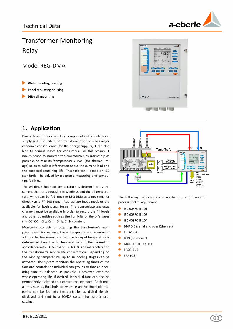
Transformer-Monitoring
Relay
Model REG-DMA
1 Wall-mounting housing
1 Panel mounting housing
1 DIN-rail mounting
1. Application Power transformers are key components of an electrical
supply grid. The failure of a transformer not only has major
economic consequences for the energy supplier, it can also
lead to serious losses for consumers. For this reason, it
makes sense to monitor the transformer as intimately as
possible, to take its "temperature curve" (the thermal im-
age) so as to collect information about the current load and
the expected remaining life. This task can - based on IEC
standards - be solved by electronic measuring and compu-
ting facilities.
The winding's hot-spot temperature is determined by the
current that runs through the windings and the oil tempera-
ture, which can be fed into the REG-DMA as a mA-signal or
directly as a PT 100 signal. Appropriate input modules are
available for both signal forms. The appropriate analogue
channels must be available in order to record the fill levels
and other quantities such as the humidity or the oil's gases
(H2, CO, CO2, CH4, C2H2, C2H4, C2H6 ) content.
Monitoring consists of acquiring the transformer's main
parameters. For instance, the oil temperature is recorded in
addition to the current. Further, the hot-spot temperature is
determined from the oil temperature and the current in
accordance with IEC 60354 or IEC 60076 and extrapolated to
the transformer's service life consumption. Depending on
the winding temperature, up to six cooling stages can be
activated. The system monitors the operating times of the
fans and controls the individual fan groups so that an oper-
ating time as balanced as possible is achieved over the
whole operating life. If desired, individual fans can also be
permanently assigned to a certain cooling stage. Additional
alarms such as Buchholz pre-warning and/or Buchholz trig-
gering can be fed into the controller as digital signals,
displayed and sent to a SCADA system for further pro-
cessing.
The following protocols are available for transmission to
process control equipment :
0 IEC 60870-5-101
0 IEC 60870-5-103
0 IEC 60870-5-104
0 DNP 3.0 (serial and over Ethernet)
0 IEC 61850
0 LON (on request)
0 MODBUS RTU / TCP
0 PROFIBUS
0 SPABUS

Transformer Monitoring Relay – REG-DMA Page 2
We take care of it.
2. REG-DMA Characteristics 0 Large backlit LCD (128 x 128 pixels) with all important
data (temperatures, voltage etc.) 0 Measurement functions (U, I, P, Q, S, cos ϕ, ϕ, I*sin ϕ, f,
Temp.) 0 Basic recorder function (3-channel line recorder) 0 Additional recorder with 4 x 64 channels and 108 MB
repository 0 Record operating hours for the transformer and the tap
changer 0 Determine the switching load (I2t value) for the tap
charger 0 Determine the hot-spot temperature for a maximum of
three windings 0 Calculate the service life consumption 0 Evaluation of the moisture content in cellulose and the
risk of bubble formation 0 Control up to six fan groups 0 Control a heater 0 Control up to two oil pumps 0 Record the run-time of the individual fan groups and oil
pumps 0 Cyclical control of the fan groups (same operating times) 0 Smart fan control (control fans based on the predicted
hot-spot temperature) 0 Record and monitor limit values for gas and water, as
well as the oil's H2 and CO content 0 Overload prediction 0 16 freely programmable binary inputs (with extension
modules up to 128) 0 11 freely programmable binary outputs (with extension
modules up to 128) 0 Freely programmable analogue inputs or outputs (mA) 0 PT100 direct input 0 Limit-value monitoring for all measured quantities 0 Programmable rated U and I values 0 AE Toolbox parameterisation software to set parame-
ters, program devices and view data, and to evaluate and archive data on the PC
0 Free programmability enables implementation of control tasks
0 RS485 (COM3) peripheral bus for additional interface modules (ANA-D, BIN-D, COM3/Modbus converter)
0 Modbus RTU Master; direct communication with sensors and devices that have a Modbus interface (COM3/Modbus converter)
0 UL certification (same hardware as the REG-DA voltage regulator)
3. Description
REG-DMA functions (maximum configuration)
1 3 x current and 2 x voltage transducer
2 Analogue inputs, PT100 (optional)
3 Binary inputs
4 Input for resistance-coded tap-position indicator (optional)
5 Auxiliary voltage
6 Indicator and processing unit
7 Analogue outputs
8 Binary outputs
9 E-LAN connection (2 x RS485 with repeater function)
10 COM1, RS232
11 COM1-S, RS232 (can be used alternatively to COM1)
12 COM2, RS232
13 COM3, RS485
14 Status notification (relay)

Page 3 Transformer Monitoring Relay – REG-DMA
3.1 Transformer Monitoring The transformer's main parameters are acquired in monitor-ing mode. The oil temperature can be entered through a mA signal or by entering it directly in PT100. The hot-spot tem-perature is determined in accordance with IEC 60354 and IEC 60076 and extrapolated to the transformer's remaining lifetime.
Fans can be switched in up to six groups as well as two oil pumps to regulate the temperature. The oil levels can be monitored and the operating hours of the fans and pumps counted.
The REG-DMA comes with ability to read mA-inputs. These inputs enable the oil temperature of a temperature trans-ducer, for example, to be read as mA signal.
If other combinations are needed, for example, the temper-ature as PT100 direct connection and the hot-spot -temperature as an mA output, the desired combination can be selected from characteristic groups 'E' and 'C'.
3.2 Transducer mode The values of all relevant quantities of an equally or arbitrar-ily loaded three-wire three-phase system are calculated from the sample values and further displayed.
Measured quantities on the displays
Voltage Ueff Current Ieff Active power P Reactive power Q Apparent power S cos ϕ Phase angle ϕ Reactive current I*sinϕ Frequency f
All of the measured and calculated values can be transferred by analogue signal or through SCADA.
REG-DMA block diagram
Transformer Monitoring Relay – REG-DMA Page 4
We take care of it.
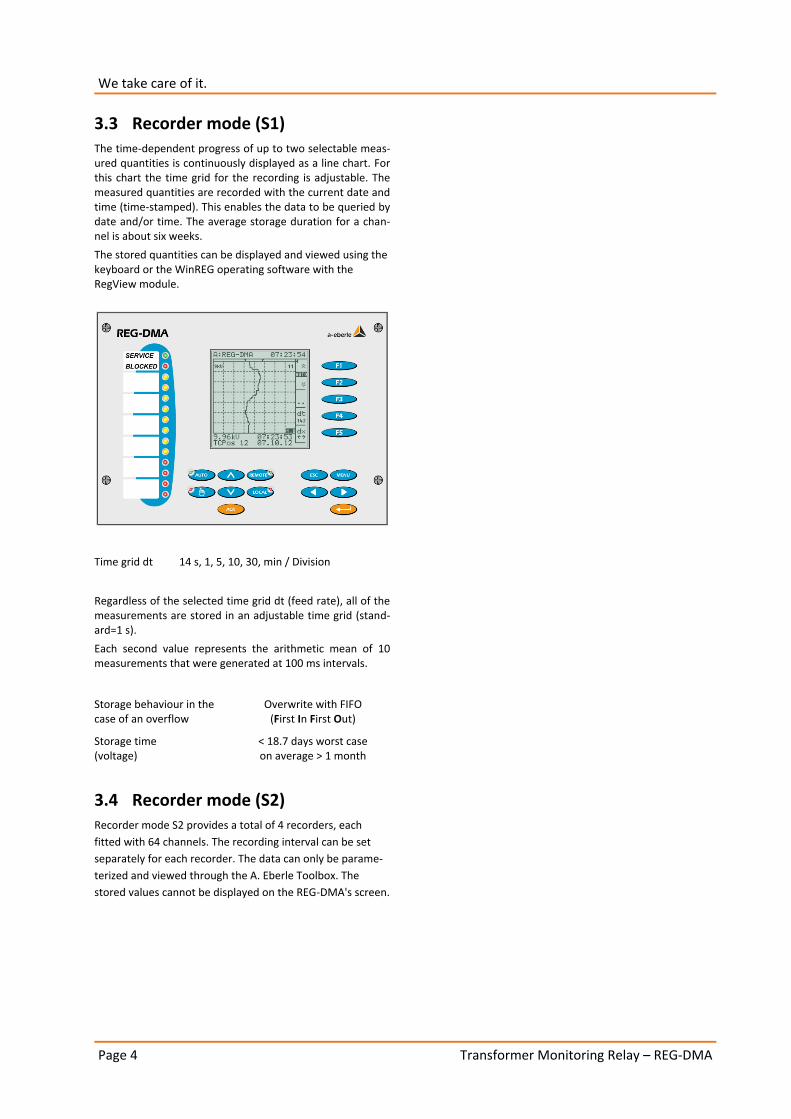
3.3 Recorder mode (S1) The time-dependent progress of up to two selectable meas-ured quantities is continuously displayed as a line chart. For this chart the time grid for the recording is adjustable. The measured quantities are recorded with the current date and time (time-stamped). This enables the data to be queried by date and/or time. The average storage duration for a chan-nel is about six weeks.
The stored quantities can be displayed and viewed using the keyboard or the WinREG operating software with the RegView module.
Time grid dt 14 s, 1, 5, 10, 30, min / Division
Regardless of the selected time grid dt (feed rate), all of the measurements are stored in an adjustable time grid (stand-ard=1 s).
Each second value represents the arithmetic mean of 10 measurements that were generated at 100 ms intervals.
Storage behaviour in the case of an overflow
Overwrite with FIFO (First In First Out)
Storage time (voltage)
< 18.7 days worst case on average > 1 month
3.4 Recorder mode (S2) Recorder mode S2 provides a total of 4 recorders, each
fitted with 64 channels. The recording interval can be set
separately for each recorder. The data can only be parame-
terized and viewed through the A. Eberle Toolbox. The
stored values cannot be displayed on the REG-DMA's screen.

Page 5 Transformer Monitoring Relay – REG-DMA
4. Technical specifications Regulations and standards
0 IEC 61010-1 / EN 61010-1
0 CAN/CSA C22.2 No. 1010.1-92
0 IEC 60255-22-1 / EN 60255-22-1
0 IEC 61326-1 / EN 61326-1
0 IEC 60529 / EN 60529
0 IEC 60068-1 / EN 60068-1
0 IEC 60688 / EN 60688
0 IEC 61000-6-2 / EN 61000-6-2
0 IEC 61000-6-4 / EN 61000-6-4
0 IEC 61000-6-5 / EN 61000-6-5 (in preparation)
8
UL Certificate Number 050505 - E242284
AC voltage inputs (UE)
Measuring voltage UE 0 ... 160 V
Shape of the curve Sinusoidal
Frequency range 16....50....60....65 Hz
Internal consumption U2 / 100 k
Overload capacity 230 V AC continuous
AC input IE)
Measuring current In 1 A / 5 A (can be selected in the software)
Shape of the curve Sinusoidal
Frequency range 16....50....60....65 Hz
Control range 0 ... In ... 2.1 In
Internal consumption 0.5 VA
Overload capacity 10 A continuous 30 In for 10 s 100 In for 1 s (max. 300A) 500 A for 5 ms
Analogue inputs (AI)
Quantity See order specifications
Input range
Y1...Y2
-20 mA...0...20 mA Y1 and Y2 programmable
Control limit ± 1.2 Y2
Voltage drop ≤ 1.5 V
Potential isolation Optocoupler
Common-mode rejec-tion
> 80 dB
Series-mode rejection > 60 dB / Decade from 10 Hz
Overload capacity ≤ 50 mA continuous
Error limit 0.5%
The regulator comes with an analogue input (e.g. for the oil temperature).
The inputs can be continuously short-circuited or operated open. All inputs are galvanically isolated from all other circuits.
Temperature input PT100
Quantity one PT100 input at Level III possible two PT100 inputs at Level II possible
Type of connection Three-wire circuit
Current through sensor < 8 mA
Potential isolation Optocoupler
Line compensation No compensation required
Transmission behaviour linear
These inputs have an open circuit monitoring.
Resistance input (tap change potentiometer, WidMod)
Quantity See order specifications
Connection Three-wire, convertible to four-wire
Total resistance in the resistor chain
R1: 2 kΩ
R3: 20 kΩ
Resistance per tap adjustable
R1: 5…100 Ω/tap
R3: 50…2000 Ω/tap
Number of taps ≤ 38
Potential isolation Optocoupler
Current through resistor chain
max. 25 mA
These inputs have an open circuit monitoring.

Transformer Monitoring Relay – REG-DMA Page 6
We take care of it.
Analogue outputs (AO)
Quantity See order specifications
Output range
Y1...Y2
-20 mA...0...20 mA Y1 and Y2 programmable
Control limit ± 1.2 Y2
Potential isolation Optocoupler
Load range 0 ≤ R ≤ 8 V / Y2
Alternating component <0.5% of Y2
The outputs can be continuously short-circuited or operated open. All output connections are galvanically isolated from all of the other circuits.
Binary inputs (BI) Inputs E1 ... E16 (... E22, ... E28)
Control signals Ust in the AC/DC range 48 V ... 250 V, 10 V ... 50 V, 80 V ... 250 V, 190 V ... 250 V, in accordance with charac-teristic Dx
Shape of the permissible curve
Rectangular, sinusoidal
48 V...250 V
– H - Level – L - Level
≥ 48 V < 10 V
10 V...50 V
– H - Level – L - Level – Input resistance
≥ 10 V < 5 V 6.8 kΩ
80 V … 250 V
– H - Level – L - Level
≥ 80 V < 40 V
190 V … 250 V
– H - Level – L - Level
≥ 176 V < 88 V
Signal frequency DC, 40 ... 70 Hz
Input resistance 108 kΩ, except 10...50 V
Potential isolation Optocoupler; Groups of four, each galvanically isolated from each other.
Debouncing Software filter with inte-grated 50Hz filter
Simplified diagram of a binary input
Binary outputs (BO)
R 1 ... R13 (... R19, ... R25) max. switching frequency
≤ 1 Hz
Potential isolation Isolated from all device-internal potentials
Contact load AC: 250 V, 5 A (cosϕ = 1.0)
AC: 250 V, 3 A (cosϕ = 0.4)
Switching capacity max. 1250 VA
DC: 30 V, 5 A resistive
DC: 30 V, 3.5 A L/R=7 ms
DC: 110 V, 0.5 A resistive
DC: 220 V, 0.3 A resistive
Switching capacity max. 150 W
Inrush current 250 V AC, 30 V DC 10 A for max. 4 s
Switching operations ≥ 5·105 electrical
Display
LC - Display 128 x 128 can display graphics
Lighting LED, switches off after 15 min
Indicator elements
The regulator has 14 light-emitting diodes (LED)
LED Service Normal operation Green
LED Blocked Faulty operation Red
LED 1 ... LED 8 Freely programmable Yellow
LED 9 ... LED 12 Freely programmable Red
Each LED can be labelled on site. If the labelling wishes are known at the time of order place-ment, labelling can be done at the factory.
Analog/Digital Conversion
Type 12 Bit successive approximation
Resolution +/- 11 bit
Sampling rate 24 samples per period, e.g. 1.2 kHz for a 50Hz signal *
*The measurement inputs have an anti-aliasing filter.
Real-time clock (RTC)
Accuracy +/- 20 ppm
Buffering Lithium button cell
Limit-value monitoring
Limit values programmable
Response times programmable
Alarm indicators LEDs are programmable

Page 7 Transformer Monitoring Relay – REG-DMA
Measured quantities (optionally as mA value) TRMS voltages U12, U23, U31 (≤ 0.25%)
Current TRMS I1, I2 , I3 (≤ 0.25%)
Active power P (≤ 0.5%)
Reactive power Q (≤ 0.5%)
Apparent power S (≤ 0.5%)
Power factor cos ϕ (≤ 0.5%)
Phase angle ϕ (≤ 0.5%)
Reactive current I · sin ϕ (≤ 1%)
Frequency f (≤ 0.05%)
Reference conditions Reference temperature 23°C ± 1 K
Input quantities UE = 0 ... 160 V IE = 0 ... 1A / 0 ... 5A
Auxiliary voltage H = Hn ± 1%
Frequency 45 Hz...65 Hz
Shape of the curve Sinusoidal, form factor 1.1107
Load (only for characteris-tics E91...E99)
Rn = 5 V / Y2 ± 1%
Other IEC 60688 - Part 1
Electrical safety Safety class I
Degree of pollution 2
Measurement category Measurement category
IV/150 V III/300 V
Operating voltages
50 V 150 V 230 V
E-LAN, COM1 ... COM3 Analogue inputs, Analogue outputs Inputs 10...50 V
Voltage inputs, current inputs
Auxiliary voltage, binary inputs (E1...E16, relay outputs R1...R13), Status
Transmission behaviour of the analogue outputs Error limit 0.05% / 0.25% / 0.5% / 1% related to
Y2 (see 'Measured quantities')
Measurement cycle time
≤ 10 ms
Electromagnetic compatibility EMC requirements EN 61326-1
Equipment class A Continuous, unmonitored operation, industrial location and EN 61000-6-2 and 61000-6-4
Interference emissions
Conducted and radiated emission
EN 61326 Table 3 EN 61000-6-4
Harmonic currents EN 61000-3-2
Voltage fluctuations and flicker
EN 61000-3-3
Disturbance immunity EN 61326 Table A1 and EN 61000-6-2
ESD IEC 61000-6-5 6kV/8kV contact/air
Electromagnetic field IEC 61000-4-3\80 – 2000 MHz: 10 V/m
Fast transient IEC 61000-4-4 4 kV/2 kV
Surge voltages IEC 61000-4-5 4 kV/2 kV
Conducted HF signals IEC 61000-4-6 150 kHz – 80 MHz: 10 V
Power-frequency magnetic fields
IEC 61000-4-8 100 A/m (50 Hz), continuous 1000 A/m (50 Hz), 1 s
Voltage dips IEC 61000-4-11 30% / 20 ms, 60% / 1 s
Voltage interruptions IEC 61000-4-11 100% / 5s
Damped oscillations IEC 61000-4-12, Class 3, 2.5 kV
Test voltages* Description Test voltage / kV Feedback control loops
Auxiliary voltage Uh 2.3 COMs, AI, AO
Auxiliary voltage Uh 2.3 BI, BO
Measuring voltage Ue 2.3 COMs, AI, AO
Measuring voltage Ue 3.3 Uh, BI, BO
Measuring voltage Ue 2.2 Ie
Measuring current Ie 2.3 COMs, AI, AO
Measuring current Ie 3.3 Uh, BI, BO
Interfaces, COMs COMs 2.3 BI, BO
Analogue outputs AO 2.3 BI, BO
Analogue outputs AO 0.5 COMs, AI
Analogue inputs AI 2.3 BI, BO
Analogue inputs AI 0.5 COMs, AO
Binary inputs BI 2.3 BI
Binary inputs BI 2.3 BO
Binary outputs BO 2.3 BO * All test voltages are AC voltages in kV that can be applied for 1 minute. The COMs are tested against each other with 0.5 kV.

Transformer Monitoring Relay – REG-DMA Page 8
We take care of it.
Power supply
Characteristic H0 H2
AC 85 … 264 V –
DC 88 ... 280 V 18 ... 72 V
Power consump-tion AC
≤ 35 VA –
Power consump-tion DC
≤ 25 W ≤ 25 W
Frequency 45 ... 400Hz –
Microfuse T1 250 V T2 250 V
The following applies to all characteristics: Voltage dips of ≤ 25 ms result neither in data loss nor mal-functions.
Ambient conditions
Temperature range
Function Transport and storage
-15°C ... +60°C -25°C ... +65°C
Dry cold IEC 60068-2-1, - 15 °C / 16 h
Dry heat IEC 60068-2-2, + 65 °C / 16 h
Humid heat constant
IEC 60068-2-78 + 40°C / 93% / 2 days
Humid heat cyclical
IEC 60068-2-30 12+12 h, 6 cycles +55°C / 93%
Drop and topple IEC 60068-2-31 100 mm drop height, unpack-aged
Vibration IEC 60255-21-1, Class 1
Shock IEC 60255-21-2, Class 1
Earthquake resistance IEC 60255-21-3, Class 1
Storage
Firmware and recorder data characteristic S2
Flash memory
Device characteris-tics and calibration data
serial EEPROM with ≥ 1000 k write/read cycles
other data and recorder data characteristic S1
MRAM, Backup to flash memory possible
The backup battery on these devices is only used to buffer the real time clock if the aux. power supply is off.
5. Mechanical design Housing
– Height
– Width
– Total depth
– Mounting depth
– Weight
Sheet steel, RAL 7035 light-grey
325 mm incl. PG connectors 250 mm 114 mm 87 mm ≤ 6.0 kg
Housing doors with silicate glass
Front panel Plastic, RAL 7035 grey on aluminium brackets
Control panel cut-out
– Height
– Width
282 mm 210 mm
Protection type IP 54
Protection type with brush sealing
IP 12
Conductor cross section and clamping torque
Level Function/ Clamp no.
Conductor / mm2 Torque
flexible solid Nm
I Measurement inputs 1..10
4 6 0.6
I BIs, relays, aux. voltage 11…60
2.5 2.5 0.6
II SCADA, all except XW90..93+97+98 87…98
0.5 0.5 ---
II SCADA, only XW90..93+97+98 87…94
2.5 2.5 0.6
II Add-ons C90..99 100…113
2.5 2.5 0.6
III COMs, AEs
61…86/200…211 1.5 1.5 0.25

Page 9 Transformer Monitoring Relay – REG-DMA
Mechanical dimensions in mm
Mechanical dimensions, panel mounting

Transformer Monitoring Relay – REG-DMA Page 10
We take care of it.
Mechanical dimensions, DIN-rail mounting, in mm
Mechanical dimensions, wall-mounting, in mm

Page 11 Transformer Monitoring Relay – REG-DMA
General information about the connection technology
The regulator has three printed circuit boards or connection levels.
The auxiliary voltage, the input voltage and the currents, as well as the relay outputs, binary inputs etc., are connected on Level I.
The hardware for all control system connections is on Level II.
The corresponding connection elements on Level II must be used for RS232 and RS485 connection technology.
When working with an Ethernet connection (coupling re-quired for IEC 61850, IEC 60870-5-104 or DNP 3.0 over Ethernet!), the corresponding plug connection is also acces-sible on Level II (RJ45 and/or fibreglass ST or LC).
For fibre optical connections up to a baud rate of 19200 (e.g. IEC 60870-5-101 or 103), the connection elements (send and receive diode as ST or FSMA connection) are directly mounted on the flange plate where they can be connected without opening the device.
Additional binary inputs and outputs, and mA inputs and outputs can be installed on Level II.
There are two slots that can be equipped with the following modules:
Module 1 : 6 binary inputs AC/DC 48 V...250 V
Module 2 : 6 relay outputs
Module 3 : 2 mA inputs
Module 4 : 2 mA outputs
Module 5 : PT100 – input
The connections for each of the COMs, the E-LAN, the ana-logue inputs and outputs and for PT100 direct input (E91 + E94) are on Level III.
Optical interfaces
The REG-DMA regulator can also be directly connected through a fibre optic interface.
Transmission and receiver equipment is available for fibre-glass and synthetic fibre optic cables.
It is also possible to choose between different mechanical connection options (ST, FSMA and LC connection technology).
Please refer to the list of characteristics for an overview of the available options.
Fibre optical connection (ST connection technology,
V17, V19)
Fibre optical connection (FSMA connection technology
V13, V15)
Fibre optical connection (1 x Ethernet ST, XW93)

Transformer Monitoring Relay – REG-DMA Page 12
We take care of it.
Optical transmitter
Serial communication up to 19200 baud (Characteristics V13 ... V19)
Product Wave length
Fibre Pmin [dBm] 1)
Pmax [dBm] 1)
Fibreglass ST Fibreglass FSMA
λ = 820 nm 50/125 μm NA=0.2
-19.8 -12.8
62.5/125 μm
NA=0.275
-16.0 -9.0
100/140 μm NA=0.3
-10.5 -3.5
200 μm HCS NA=0.37
-6.2 +1.8
All-plastic ST
λ = 650 nm 1 mm POF -7.5 -3.5
200 μm HCS -18.0 -8.5
All-plastic FSMA
λ = 650 nm 1 mm POF -6.2 0.0
200 μm -16.9 -8.5
Communication over Ethernet 100 Mbit (100 Base Fx) (Characteristics XW92, XW93.x, XW95.x, XW96.1 and XW98)
Product Wave length
Fibre Pmin [dBm] 1)
Pmax [dBm] 1)
Fibreglass ST Fibreglass LC
1310 nm 62.5/125 μm
NA=0.275
-20 -14
1) TA = 0..70°C, IF = 60 mA, measured after 1 m fibre optic cable
Optical receiver
Serial communication up to 19200 baud (Characteristics V13 ... V19)
Product Wave length
Fibre Pmin [dBm] 2)
Pmax [dBm] 2)
Fibreglass ST Fibreglass FSMA
λ = 820 nm 100/140 μm NA=0.3
-24.0 -10.8
All-plastic ST
λ = 650 nm 1 mm POF -20.0 0.0
200 μm HCS -22.0 -2.0
All-plastic FSMA
λ = 650 nm 1 mm POF -21.6 -2.0
200 μm -23.0 -3.4
Communication over Ethernet 100 Mbit (100 Base Fx) (Characteristics XW92, XW93.x, XW95.x, XW96.1 and XW98)
Product Wave length
Fibre Pmin [dBm] 2)
Pmax [dBm] 2)
Fibreglass ST Fibreglass LC
1310 nm 62.5/125 μm
NA=0.275
-14 -32
2) TA = 0...70°C, VCC = 5 V±5%, output level LOW (active)
Page 13 Transformer Monitoring Relay – REG-DMA
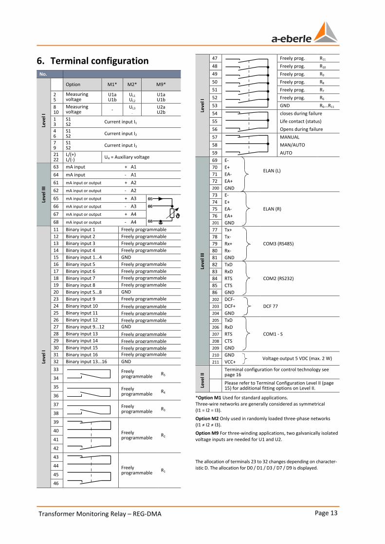
6. Terminal configuration No.
Leve
l I
Option M1* M2* M9*
2 5
Measuring voltage Measuring voltage
U1a U1b
UL1 UL2
U1a U1b
8 10
Measuring voltage Measuring voltage
- UL3
- U2a U2b
1 3
S1 S2
Current input I1
4 6
S1 S2
Current input I2
7 9
S1 S2 Current input I3
21 22
L/(+) L/(-)
UH = Auxiliary voltage
Leve
l III
63 mA input + A1
64 mA input - A1
61 mA input or output + A2
62 mA input or output - A2
65 mA input or output + A3
66 mA input or output - A3
67 mA input or output + A4
68 mA input or output - A4
Leve
l I
11 Binary input 1 Freely programmable
12 Binary input 2 Freely programmable
13 Binary input 3 Freely programmable
14 Binary input 4 Freely programmable
15 Binary input 1...4 GND
16 Binary input 5 Freely programmable
17 Binary input 6 Freely programmable
18 Binary input 7 Freely programmable
19 Binary input 8 Freely programmable
20 Binary input 5...8 GND
23 Binary input 9 Freely programmable
24 Binary input 10 Freely programmable 25 Binary input 11 Freely programmable 26 Binary input 12 Freely programmable 27 Binary input 9...12 GND
28 Binary input 13 Freely programmable 29 Binary input 14 Freely programmable 30 Binary input 15 Freely programmable 31 Binary input 16 Freely programmable
32 Binary input 13...16 GND
33 Freely programmable
R5 34
35 Freely programmable
R4 36
37 Freely programmable R3
38
39
Freely programmable
R2 40
41
42
43
Freely programmable R1
44
45
46
Leve
l I
47 Freely prog. R11
48 Freely prog. R10
49 Freely prog. R9
50 Freely prog. R8
51 Freely prog. R7
52 Freely prog. R6
53 GND R6...R11
54 closes during failure
55 Life contact (status)
56 Opens during failure
57 MANUAL
58 MAN/AUTO
59 AUTO
Leve
l III
69 E-
ELAN (L) 70 E+
71 EA-
72 EA+
2000
GND
73 E-
ELAN (R)
74 E+
75 EA-
76 EA+
2010
GND
77 Tx+
COM3 (RS485)
78 Tx-
79 Rx+
80 Rx-
81 GND
82 TxD
COM2 (RS232)
83 RxD
84 RTS
85 CTS
86 GND
202 DCF-
203 DCF+ EA+
DCF 77
204 GND
205 TxD
206 RxD
207 RTS COM1 - S
208 CTS
209 GND
210 GND Voltage output 5 VDC (max. 2 W)
211 VCC+
Leve
l II
Terminal configuration for control technology see page 16
Please refer to Terminal Configuration Level II (page 15) for additional fitting options on Level II.
*Option M1 Used for standard applications. Three-wire networks are generally considered as symmetrical (I1 = I2 = I3).
Option M2 Only used in randomly loaded three-phase networks (I1 ≠ I2 ≠ I3).
Option M9 For three-winding applications, two galvanically isolated voltage inputs are needed for U1 and U2.
The allocation of terminals 23 to 32 changes depending on character-istic D. The allocation for D0 / D1 / D3 / D7 / D9 is displayed.
ϑ

Transformer Monitoring Relay – REG-DMA Page 14
We take care of it.
Position of the terminal connections
Characteristics D0, D1, D4, D7, D9
Position of the terminal connections
Characteristics D2, D3, D5, D6, D8

Page 15 Transformer Monitoring Relay – REG-DMA
6.1 Terminal Configuration Level II Characteristics: C90...C99
Characteristic C90 – (e.g. 2 x PT100, other combinations are
possible) No.
Mo
du
le 5
100
PT100
Ik+
A10 101 Ue+ 102 Ue- 103 Ik-
Mo
du
le 5
104
PT100
Ik+
A12 105 Ue+ 106 Ue- 107 Ik-
Characteristic C91 – 6 additional binary inputs AC/DC 48 V ... 250 V No.
Mo
du
le 1
100 Binary input E17 101 Binary input E18 102 Binary input E19 103 Binary input E20 104 Binary input E21 105 Binary input E22 106 GND E17 … E22
Characteristic C92 – 12 additional binary inputs AC/DC 48 V ... 250 V No.
Mo
du
le 1
100 Binary input E17 101 Binary input E18 102 Binary input E19 103 Binary input E20 104 Binary input E21 105 Binary input E22 106 GND E17 … E22
Mo
du
le 1
107 Binary input E23 108 Binary input E24 109 Binary input E25 110 Binary input E26 111 Binary input E27 112 Binary input E28 113 GND E23 … E28
Characteristic C93 – 6 additional relay outputs (NOC) No.
Mo
du
le 2
100 R12 101 R13 102 R14 103 R15 104 R16 105 R17 106 GND R12 … R17
Characteristic C94 – 12 additional relay outputs (NOC) No.
Mo
du
le 2
100 R12 101 R13 102 R14 103 R15 104 R16 105 R17 106 GND R12 … R17
Mo
du
le 2
107 R18
8 108 R19 109 R20 110 R21 111 R22 112 R23 113 GND R18 … R23
Characteristic C95– 6 additional binary inputs AC/DC 48 V ... 250 V
and 6 additional relay outputs (NOC) No.
Mo
du
le 1
100 Binary input E17 101 Binary input E18 102 Binary input E19 103 Binary input E20 104 Binary input E21 105 Binary input E22 106 GND E17 … E22
Mo
du
le 2
107 R12 108 R13 109 R14 110 R15 111 R16 112 R17 113 GND R12 … R17
Characteristic C96 – 2 additional analogue inputs No.
Mo
du
le 3
100 analogue input + A10 101 - 102
analogue input +
A11 103 -
Characteristic C97 – 4 additional analogue inputs No.
Mo
du
le 3
100 analogue input + A10 101 - 102
analogue input +
A11 103 -
Mo
du
le 3
104 analogue input + A12 105 - 106
analogue input +
A13 107 -
Characteristic C98 – 2 additional analogue outputs No.
Mo
du
le 4
100 analogue output + A10 101 - 102
analogue output +
A11 103 -
Characteristic C99 – 4 additional analogue outputs
Nr.
Mo
du
le 4
100 analogue output
+ A10
101 - 102
analogue output +
A11 103 -
Mo
du
le 4
104 analogue output + A12 105 - 106
analogue output +
A13 107 -

Transformer Monitoring Relay – REG-DMA Page 16
We take care of it.
6.2 Terminal Configuration for Control System Level II
Characteristics: Z10..15, 17..23, 90, 91, 99, XW90…98
Characteristics Z10..15, 17..20, 90, 91 – REG-P communication interface No.
CO
M1
RS4
85
87 RS485-N (B)
88 RS485-P (A)
CO
M1
RS2
32
89 RS232-TxD 90 RS232-RxD 91 RS232-RTS 92 RS232-CTS 93 RS232-GND
PE 94 PE
CO
M1
fib
re o
pti
c
cab
le
95 Fibre optic cable In
Fibre optic cable module Fibre optic
cable
96 Fibre optic cable Out 97 Fibre optic cable GND 98 Fibre optic cable VCC
Characteristics Z22..23 – REG-PM communication interface No.
CO
M1
RS4
85
92 RS485-P (A)
93 RS485-N (B)
94 RS485-GND
CO
M1
RS2
32
87 RS232-TxD
89 RS232-RxD 88 RS232-RTS 90 RS232-CTS 91 RS232-GND
CO
M1
fib
re
op
tic
cab
le
96 Fibre optic cable In
Fibre optic cable module Fibre optic
cable
97 Fibre optic cable Out 95 Fibre optic cable GND
98 Fibre optic cable VCC
PA
RA
M
(SU
B-D
)
Parameter Interface
Characteristic Z21 – REG-LON communication interface No.
Fib
re o
p-
tic
cab
le Fibre optic cable In
Fibre optic cable module Fibre optic
cable
Fibre optic cable Out Fibre optic cable GND Fibre optic cable VCC
Characteristic Z99 – Profibus-DP communication interface No.
PA
RA
M
(RJ1
1)
1 RS232-GND 2 RS232-GND 3 RS232-RxD 4 RS232-TxD
Pro
fib
us-
DP
(SU
B-D
)
3 B-Line (Rx/Tx +) 4 RTS
5 GND BUS 6 +5 V BUS 8 A-Line (Rx/Tx -)
Characteristic XW90..93+97+98 – REG-PE communication interface No.
PA
RA
M 1
87 RS232-RxD
88 RS232-TxD
89 RS232-GND
90 RS232-GND-SCR
PA
RA
M 2
91 RS232-RxD 92 RS232-TxD 93 RS232-GND 94 RS232-GND-SCR
Eth
ern
et
RJ45 connector or Fibre optic cable (ST
or LC)
Characteristic XW94..96 – REG-PED communication interface No.
CO
M1
87 RS485-P (A) 88 RS485-N (B) 89 RS232-TxD 90 RS232-RxD 91 RS232-RTS 92 RS232-CTS 93 RS232-GND
PE 94 PE/Shield
PA
RA
M 95 PARAM-RxD
96 PARAM-TxD
97 PARAM-GND
Eth
ern
et 1
RJ45 connector or Fibre optic cable (ST
or LC)
Eth
ern
et 2
RJ45 connector or Fibre optic cable (ST
or LC)
Page 17 Transformer Monitoring Relay – REG-DMA
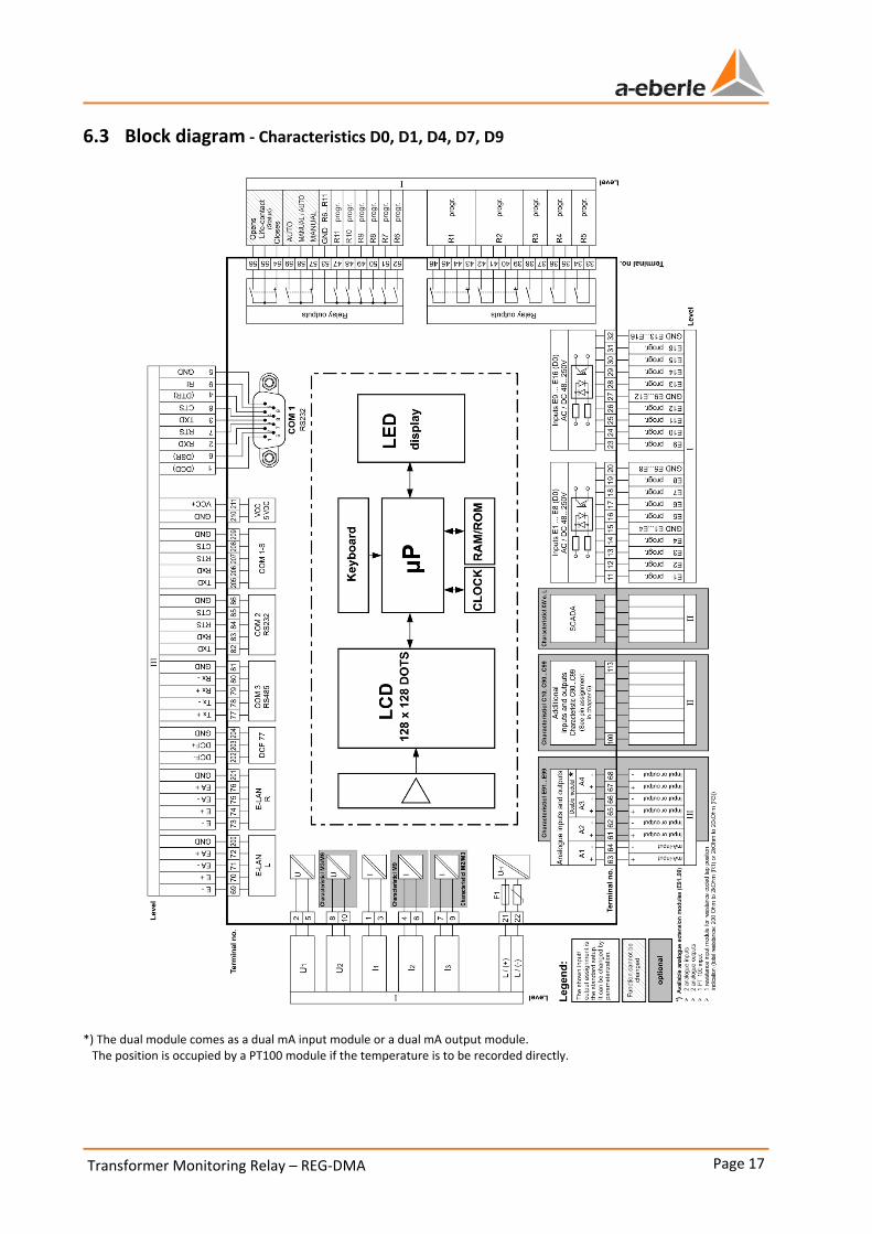
6.3 Block diagram - Characteristics D0, D1, D4, D7, D9
*) The dual module comes as a dual mA input module or a dual mA output module. The position is occupied by a PT100 module if the temperature is to be recorded directly.

Transformer Monitoring Relay – REG-DMA Page 18
We take care of it.
6.4 Block diagram - Characteristics D2, D3, D5, D6, D8
*) The dual module comes as a dual mA input module or a dual mA output module. The position is occupied by a PT100 module if the temperature is to be recorded directly.
Page 19 Transformer Monitoring Relay – REG-DMA
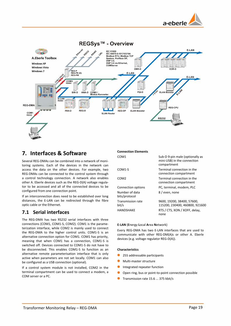
7. Interfaces & Software Several REG-DMAs can be combined into a network of moni-toring systems. Each of the devices in the network can access the data on the other devices. For example, two REG-DMAs can be connected to the control system through a control technology connection. A network also enables other A. Eberle devices such as the REG-D(A) voltage regula-tor to be accessed and all of the connected devices to be configured from one connection point.
If an interconnection does need to be established over long distances, the E-LAN can be redirected through the fibre optic cable or the Ethernet.
7.1 Serial interfaces
The REG-DMA has two RS232 serial interfaces with three connections (COM1, COM1-S, COM2). COM1 is the parame-terization interface, while COM2 is mainly used to connect the REG-DMA to the higher control units. COM1-S is an alternative connection option for COM1. COM1 has priority, meaning that when COM1 has a connection, COM1-S is switched off. Devices connected to COM1-S do not have to be disconnected. This enables COM1-S to function as an alternative remote parameterisation interface that is only active when parameters are not set locally. COM1 can also be configured as a USB connection (optional).
If a control system module is not installed, COM2 in the terminal compartment can be used to connect a modem, a COM server or a PC.
Connection Elements
COM1 Sub-D 9-pin male (optionally as mini-USB) in the connection compartment
COM1-S Terminal connection in the connection compartment
COM2 Terminal connection in the connection compartment
Connection options PC, terminal, modem, PLC
Number of data bits/protocol
8 / even, none
Transmission rate bit/s
9600, 19200, 38400, 57600, 115200, 230400, 460800, 921600
HANDSHAKE RTS / CTS, XON / XOFF, delay, none
E-LAN (Energy Local Area Network)
Every REG-DMA has two E-LAN interfaces that are used to communicate with other REG-DM(A)s or other A. Eberle devices (e.g. voltage regulator REG-D(A)).
Characteristics
0 255 addressable participants
0 Multi-master structure
0 Integrated repeater function
0 Open ring, bus or point-to-point connection possible
0 Transmission rate 15.6 ... 375 kbit/s
A.Eberle Toolbox
Windows XP
Windows Vista
Windows 7

Transformer Monitoring Relay – REG-DMA Page 20
We take care of it.
COM3 (peripheral interface)
To connect up to 16 interface modules (BIN-D, ANA-D) to a REG-DMA in any combination. COM3 is an RS485 interface.
Optionally, a fibre optic cable can be used to connect COM3 devices that are not in the vicinity of the REG-DMA.
The COM3/Modbus converter can also be connected in order to establish direct serial communication with other Modbus devices. This enables the REG-DMA to acquire values such as the winding temperature or the gas-in-oil ratio from other devices and transmit them to the control technology or record them in the recorder.
Time synchronisation input (DCF input)
The time synchronisation input enables the time on the REG-DMA to be synchronised using a DCF77 signal. The input is designed for an RS485 (5 V) and can be wired to several devices as time synchronisation bus. The termination (terminating resistor) can be switched on and off by using jumpers on the CPU board. If a DCF signal cannot be re-ceived, a GPS clock or control system card that emulates a DCF signal can be used. Time can also be synchronised through the control system.
7.2 A.Eberle Toolbox - Parameteriza-tion and configuration software
The A.Eberle Toolbox is used to parameterize and pro-gramme the system, and to archive and view recorded data.
The A.Eberle Toolbox runs on the following operating sys-tems:
0 Windows XP SP 3 0 Windows Vista 0 Windows 7 0 Windows 8
REG-DMA - Parameters (selection)
Parameter Setting range
Rated current for each cooling stage
0...3000A
Thermal time constant for each cooling stage
0..50000 s
Hot-spot temperature in-crease Hgr
0...90K
Winding exponent y 0…3
Basis of the control
(Cooling stage control)
Oil Winding SmrtCtrl
Temperature limit for each cooling stage
-30…200 °C
IEC equation IEC 60354
IEC 60076
Type of air cooling AN AF
Parameter Setting range
Type of oil cooling
ON OF OD ON/OF ON/OD
Fan assignment fixed
cyclic
Number of fans 1…6
Transformer oil temperature alarm
0...150 °C
Tap changer oil temperature alarm
0...150 °C
Winding temperature alarm 0...200 °C
Winding temperature trigger
0...200 °C
Transformer oil level alarm 0 … 150 %
Tap changer oil level alarm 0 … 150 %
Gas-in-oil alarm 0...1000000 ppm
Water-in-oil alarm 0...1000000 ppm
H2-in-oil alarm 0...1000000 ppm
CO-in-oil alarm 0...1000000 ppm
Operating hours transformer
0…999999h
Service life consumption transformer
0…999999h
Operating hours fans 0…999999h
Operating hours oil pumps 0…999999h
Operating hours tap changer
0…999999h
Switching load tap changer 0…900000000000 A2s
max. Winding temperature -30…200 °C
Time to max. temperature 1..7200 s
Time delay limit values (adjustable for every limit value)
0...900 s

Page 21 Transformer Monitoring Relay – REG-DMA
8. Order specifications 0 Only one unit can be ordered for codes with the same capital letter.
0 When a code's capital letter is followed by the number 9, additional information may be required.
0 When a code's capital letter is followed only by zeros, the code may be omitted.
0 X characteristics such as XE91 cannot be combined with all of the other characteristics. Please read the notes and explana-tions.
CHARACTERISTIC CODE
Transformer Monitoring System – REG-DMA 0 with dual E-LAN interface COM2, COM3 and an mA input channel, e.g. to measure the oil temperature 0 Comes with 16 binary inputs and 12 relay outputs plus a status output, and includes the parameterization
software to set parameters, program and view all data. Includes connection cable 0 Digital 3-channel line recorder 0 additional recorder function with 4 x 64 channels and 108 MB internal memory Note: COM2 is only freely accessible when operated without control system.
REG-DMA
Model 0 Panel mounting or wall mounting (H x W x D) 307 x 250 x 102 mm including flange plate with brush element 0 with DIN-rail adapter
B0 B1
Serial interface COM1 0 RS232 with SUB-D connector (9-pin male), standard if characteristic I is not specified 0 USB (Mini USB connector)
I0 I1
Power supply 0 external AC 85 V ... 110V ... 264 V / DC 88 V ... 220V ... 280V 0 external DC 18 V ... 60V ... 72V
H0 H2
Input current (can be changed at a later stage) 0 IEN 1A 0 IEN 5A
F1 F2
Voltage and current measurement 0 Three-wire three-phase system with equal load 0 Three-wire three-phase system with random load (ARON connection) 0 other transducer applications (2 x I, 2 x U, e.g. triple-wound)
M1 M2 M9
additional analogue inputs and outputs 0 without 0 with one PT100 input 0 with two mA inputs 0 with two mA outputs 0 with one PT100 input and one mA output 0 with two mA inputs and one mA output 0 with three mA outputs 0 Tap change potentiometer input total resistance 180 Ω ... 2 kΩ, min. 5 Ω/tap 0 Tap potentiometer input total resistance 2 kΩ ... 20 kΩ, min. 50 Ω/tap 0 other combinations of inputs and outputs
E00 E91 E92 E93 E94 E95 E96 E97 E98 E99
Binary inputs and tap change potentiometer input 0 16 units binary inputs AC/DC 48...250 V (E1...E16) 0 8 units binary inputs AC/DC 10..50 V (E1…E8) and 8 units AC/DC 48...250 V (E9…E16) 0 16 units binary inputs AC/DC 10…50 V (E1…E16) 0 16 units binary inputs AC/DC 190...250 V (E1...E16) 0 16 units binary inputs AC/DC 80...250 V (E1...E16) 0 1 tap change potentiometer input (total resistance 180 ... 2k Ω) and 8 binary inputs AC/DC 48...250 V 0 1 tap change potentiometer input (total resistance >2 ... 20 kΩ) and 8 binary inputs AC/DC 10…50 V 0 1 tap change potentiometer input (total resistance 180 ... 2 kΩ) and 8 binary inputs AC/DC 10…50 V 0 1 tap change potentiometer input (total resistance >2 ... 20 kΩ) and 8 binary inputs AC/DC 48…250V 0 1 tap change potentiometer input (total resistance >2 ... 20k Ω) and 8 binary inputs AC/DC 80...250 V
D0 D1 D4 D7 D9 D2 D3 D5 D6 D8
Transformer Monitoring Relay – REG-DMA Page 22
We take care of it.
CHARACTERISTIC CODE
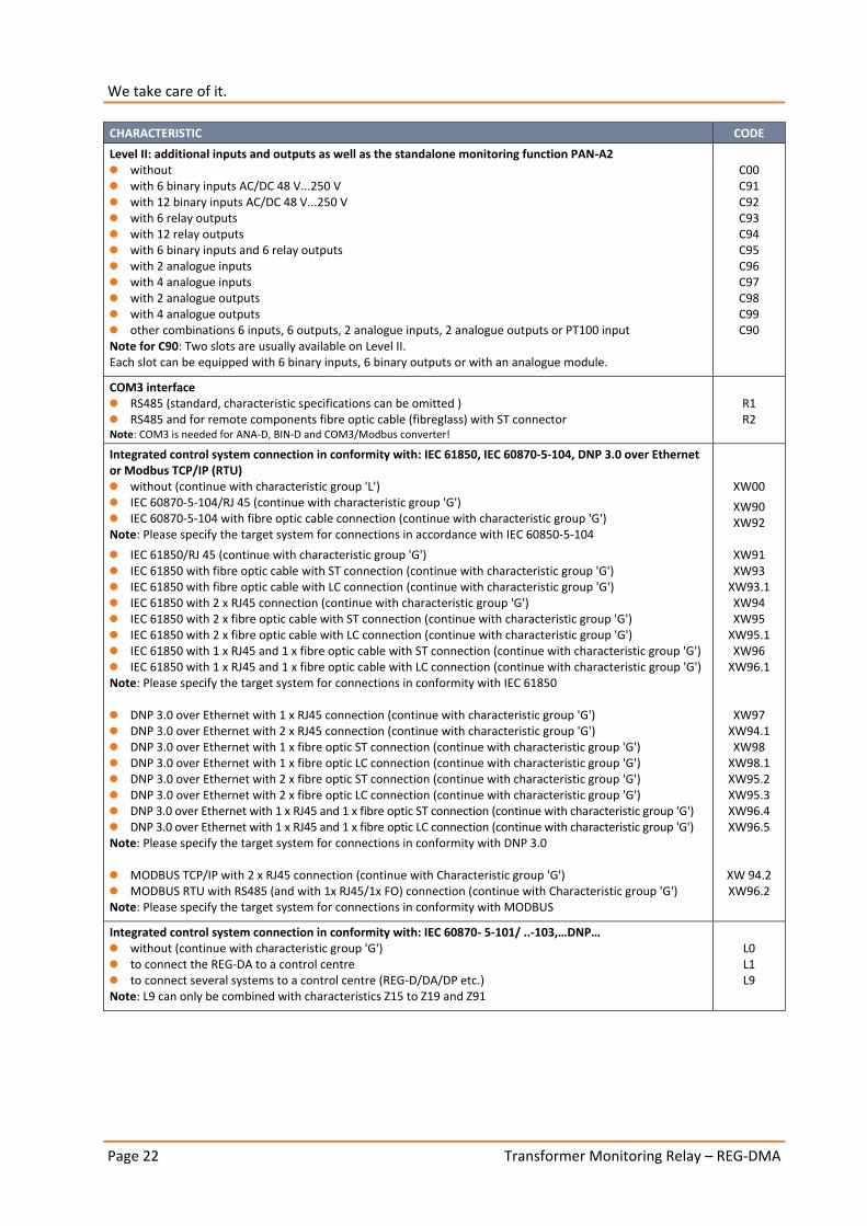
Level II: additional inputs and outputs as well as the standalone monitoring function PAN-A2 0 without 0 with 6 binary inputs AC/DC 48 V...250 V 0 with 12 binary inputs AC/DC 48 V...250 V 0 with 6 relay outputs 0 with 12 relay outputs 0 with 6 binary inputs and 6 relay outputs 0 with 2 analogue inputs 0 with 4 analogue inputs 0 with 2 analogue outputs 0 with 4 analogue outputs 0 other combinations 6 inputs, 6 outputs, 2 analogue inputs, 2 analogue outputs or PT100 input Note for C90: Two slots are usually available on Level II. Each slot can be equipped with 6 binary inputs, 6 binary outputs or with an analogue module.
C00 C91 C92 C93 C94 C95 C96 C97 C98 C99 C90
COM3 interface 0 RS485 (standard, characteristic specifications can be omitted ) 0 RS485 and for remote components fibre optic cable (fibreglass) with ST connector Note: COM3 is needed for ANA-D, BIN-D and COM3/Modbus converter!
R1 R2
Integrated control system connection in conformity with: IEC 61850, IEC 60870-5-104, DNP 3.0 over Ethernet or Modbus TCP/IP (RTU) 0 without (continue with characteristic group 'L') 0 IEC 60870-5-104/RJ 45 (continue with characteristic group 'G') 0 IEC 60870-5-104 with fibre optic cable connection (continue with characteristic group 'G') Note: Please specify the target system for connections in accordance with IEC 60850-5-104
0 IEC 61850/RJ 45 (continue with characteristic group 'G') 0 IEC 61850 with fibre optic cable with ST connection (continue with characteristic group 'G') 0 IEC 61850 with fibre optic cable with LC connection (continue with characteristic group 'G') 0 IEC 61850 with 2 x RJ45 connection (continue with characteristic group 'G') 0 IEC 61850 with 2 x fibre optic cable with ST connection (continue with characteristic group 'G') 0 IEC 61850 with 2 x fibre optic cable with LC connection (continue with characteristic group 'G') 0 IEC 61850 with 1 x RJ45 and 1 x fibre optic cable with ST connection (continue with characteristic group 'G') 0 IEC 61850 with 1 x RJ45 and 1 x fibre optic cable with LC connection (continue with characteristic group 'G') Note: Please specify the target system for connections in conformity with IEC 61850 0 DNP 3.0 over Ethernet with 1 x RJ45 connection (continue with characteristic group 'G') 0 DNP 3.0 over Ethernet with 2 x RJ45 connection (continue with characteristic group 'G') 0 DNP 3.0 over Ethernet with 1 x fibre optic ST connection (continue with characteristic group 'G') 0 DNP 3.0 over Ethernet with 1 x fibre optic LC connection (continue with characteristic group 'G') 0 DNP 3.0 over Ethernet with 2 x fibre optic ST connection (continue with characteristic group 'G') 0 DNP 3.0 over Ethernet with 2 x fibre optic LC connection (continue with characteristic group 'G') 0 DNP 3.0 over Ethernet with 1 x RJ45 and 1 x fibre optic ST connection (continue with characteristic group 'G') 0 DNP 3.0 over Ethernet with 1 x RJ45 and 1 x fibre optic LC connection (continue with characteristic group 'G') Note: Please specify the target system for connections in conformity with DNP 3.0 0 MODBUS TCP/IP with 2 x RJ45 connection (continue with Characteristic group 'G') 0 MODBUS RTU with RS485 (and with 1x RJ45/1x FO) connection (continue with Characteristic group 'G') Note: Please specify the target system for connections in conformity with MODBUS
XW00
XW90 XW92
XW91 XW93
XW93.1 XW94 XW95
XW95.1 XW96
XW96.1
XW97 XW94.1 XW98
XW98.1 XW95.2 XW95.3 XW96.4 XW96.5
XW 94.2 XW96.2
Integrated control system connection in conformity with: IEC 60870- 5-101/ ..-103,…DNP… 0 without (continue with characteristic group 'G') 0 to connect the REG-DA to a control centre 0 to connect several systems to a control centre (REG-D/DA/DP etc.) Note: L9 can only be combined with characteristics Z15 to Z19 and Z91
L0 L1 L9

Page 23 Transformer Monitoring Relay – REG-DMA
CHARACTERISTIC CODE
Connection type 0 Copper
– RS232
– RS485 2-wire operation only 0 Fibre optic cable with FSMA connection technology
– Fibreglass (wave length 800...900 nm, range 2000 m)
– Plastic (wave length 620...680 nm, range 50 m) 0 Fibre optic cable with ST connection technology
– Fibreglass (wave length 800...900 nm, range 2000 m)
– Plastic (wave length 620...680 nm, range 50 m)
V10 V11
V13 V15
V17 V19
Protocol 0 IEC60870-5-103 for ABB 0 IEC60870-5-103 for Areva 0 IEC60870-5-103 for SAT 0 IEC60870-5-103 for Siemens (LSA/SAS) 0 IEC60870-5-103 for Sprecher Automation 0 IEC60870-5-103 for others 0 IEC60870-5-101 for ABB 0 IEC60870-5-101 for IDS 0 IEC60870-5-101 for SAT 0 IEC60870-5-101 for Siemens (LSA/SAS) 0 IEC60870-5-101 for others 0 DNP 3.00 0 LONMark (on request) 0 SPABUS 0 MODBUS RTU 0 Profibus-DP (always with V11!) (on request)
Z10 Z11 Z12 Z13 Z14 Z90 Z15 Z17 Z18 Z19 Z91 Z20 Z21 Z22 Z23 Z99
Operating instructions 0 German 0 English 0 Other (On request)
G1 G2 G9
Display language 0 German 0 English 0 Spanish 0 Other (On request)
A1 A2 A4
A11
Use of IEC 61850 GOOSE applications GOOSE
IEC 61850 with bonding in active backup mode Bonding
DCF simulation over NTP and E-LAN extension over Ethernet (CSE) Note: Only in combination with XW94.x, XW95.x, XW96.x
DCF/E-LAN

Transformer Monitoring Relay – REG-DMA Page 24
We take care of it.
REG-DMA accessories ID No.
Fuses, batteries:
1 pack microfuses T1 L 250 V, 1 A, for auxiliary voltage range H0 582.1002
1 pack microfuses T2 L 250 V, 2 A, for auxiliary voltage range H2 582.1019
1 lithium battery (pluggable) 570.0003.00
1 lithium battery (solderable) on request
1 button cell CR1632 on request
Connection technology:
PC connection cable (null-modem cable) 582.020B.00
USB cable (USB A <-> USB B Mini) 582.020U.00
Modem connection cable 582.2040
RS232 10 m extension cable 582.2040.10
USB/RS232 adapter with integrated null-modem cable (FDTI), 1.5m 111.9046.01
E-LAN interface -> fibreglass, (RS485 conversion to fibre optic cable), ST fibre optic cable connection, 2 units needed for each line
111.9030.10
E-LAN interface -> fibreglass, (RS485 conversion to fibre optic cable), LC fibre optic cable connection, 2 units needed for each line
111.9030.11
E-LAN booster, Uh: DC 20..75 V, DIN-rail mounting housing 22.5 mm width, if necessary with mains adapter H1 111.9030.36
111.9027.02
E-LAN router, one outgoing circuit with booster, Uh: DC 20..75 V, DIN-rail mounting housing 22.5 mm width, if necessary with mains adapter H1 111.9030.36
111.9027.03
Time synchronisation:
Radio clock (DFC 77) 111.9024.01
GPS radio clock NIS time, RS485, Uh: AC 85 V ... 110V ... 264 V / DC 88 V ... 220V ... 280V 111.9024.45
GPS radio clock NIS time, RS485, Uh: DC 18 V ... 60V ... 72V 111.9024.46
GPS radio clock NIS time, RS232, Uh: AC 85 V ... 110V ... 264 V / DC 88 V ... 220V ... 280V 111.9024.47
GPS radio clock NIS time, RS232, Uh: DC 18 V ... 60V ... 72V 111.9024.48
Modems:
Develo MicroLink 56Ki analogue modem, tabletop device incl. 230 V AC mains adapter 111.9030.02
Develo MicroLink 56Ki analogue modem, DIN-rail mounting device incl. 230 V AC mains adapter 111.9030.03
Industrial analogue modem that can be used as dial-up modem or dedicated line; (Uh: AC 20..260 V/DC 14 V..280 V) with DIN-rail mounting adapter; can be used with the PC and the device.
111.9030.17
Insys industrial analogue modem that can be used as a dedicated line; Supply voltage DC: 10…60 V, can be used with PC and device!
111.9030.20
ISDN modem for DIN-rail mounting mount; Uh: DC 10 … 60 V 111.9030.27
ISDN modem as tabletop device; incl. 230 V AC mains adapter 111.9030.37
GPRS modem (Insys) for DIN-rail mounting mount; incl. magnet foot antenna and parameterisation software; Uh: DC 10 ..60 V
111.9030.29
Power supply:
Phoenix mains adapter for DIN-rail mounting: In: AC 120 V...230 V, DC 90 … 250 V, Out: DC 24 V 111.9005.02
Mains adapter for DIN-rail mounting: In: AC 80 V...250 V; Out: DC 24 V 111.9030.31
Mains adapter for DIN-rail mounting: In: DC 18 V...60 V...72 V; Out: DC 24 V 111.9030.32
Mains adapter for E-LAN router or booster: In: AC 100 to 240 V, Out: 24 V/1.3 A 111.9030.36
UPS HighCAP2403-1AC, In: 230 V AC Out: 24 V DC, max. 3 A, 1000 Joule (1 kW), DIN-rail 111.9030.38

Page 25 Transformer Monitoring Relay – REG-DMA
REG-DMA accessories ID No.
Additional input and output module:
Analogue input module (2 inputs) 320.0004.00
Analogue output module (2 outputs) 320.0003
Input module for tap-potentiometer total resistance 180 ...2 kΩ, min. 5 Ω/tap 320.0002.01
Input module for tap-potentiometer total resistance 2 ...20 kΩ, min. 50 Ω/tap 320.0002.03
Input module for PT100 in conformity with DIN 43760 in three-wire circuit 320.0005.01
Operating instructions:
Additional operating instructions for REG-DMA (please specify the language) GX
Software for REG-DMA CODE
REGView as CD-ROM Parameter software enhanced with Collector and RegView functions to archive and view data recorded with REG-DM(A).
REGView
General add-ons CODE
Profibus-DP module Includes RS485 interface with connection cable; for external power supply with 24 V DC
Model 0 Can be mounted on DIN-rail mounting (120 x 75 x 27 mm) ext. 24 V power supply adapter
Profi-DP
B0
TCP/IP adapter 0 10 Mbit mountable on DIN-rail mounting with mains adapter for Uh AC 230 V 0 100 Mbit
REG-COM A01 A90
COM3 converter COM3 to Modbus converter to connect external devices with Modbus interface to the transformer moni-toring module. For example, to analyse the gas-in-oil ratio online, directly measure the winding temperature, etc. 0 Auxiliary voltage – AC 85…264 V, DC 88 … 280 V, DC 18 … 72 V
– DC 18 … 72 V
COM3-MOD
H1 H2
IRIG-DCF77 converter 0 AC 85 V … 110 V …264 V / DC 88 V … 220 V … 280 V 0 DC 18 V … 60 V … 72 V 0 as wall-mounting housing 20 TE
IRIG-DCF H1 H2 B2

Transformer Monitoring Relay – REG-DMA Page 26
We take care of it.
Notes

Page 27 Transformer Monitoring Relay – REG-DMA
Notes

A. Eberle GmbH & Co. KG
Frankenstraße 160 D-90461 Nuremberg
Tel.: +49-(0)911-62 81 08-0 Fax: +49-(0)911-62 81 08-96 Email: [email protected]
http://www.a-eberle.de
Provided by:
_______________________________
Copyright 2015 by A. Eberle GmbH & Co. KG
Subject to change without prior notice.