trace heating board setup-2013 - real systems controls ltd. · on board diagnostic led led on =...
TRANSCRIPT
Real Systems Controls L imited Unit 14/14a, Woodend Mill, South Hill, Springhead, Oldham, OL4 5DR Tel: 0161 620 7880 | Fax: 0161 627 2083 | Email: [email protected]
TRACE HEATING BOARD SETUP/TEST INSTRUCTIONS
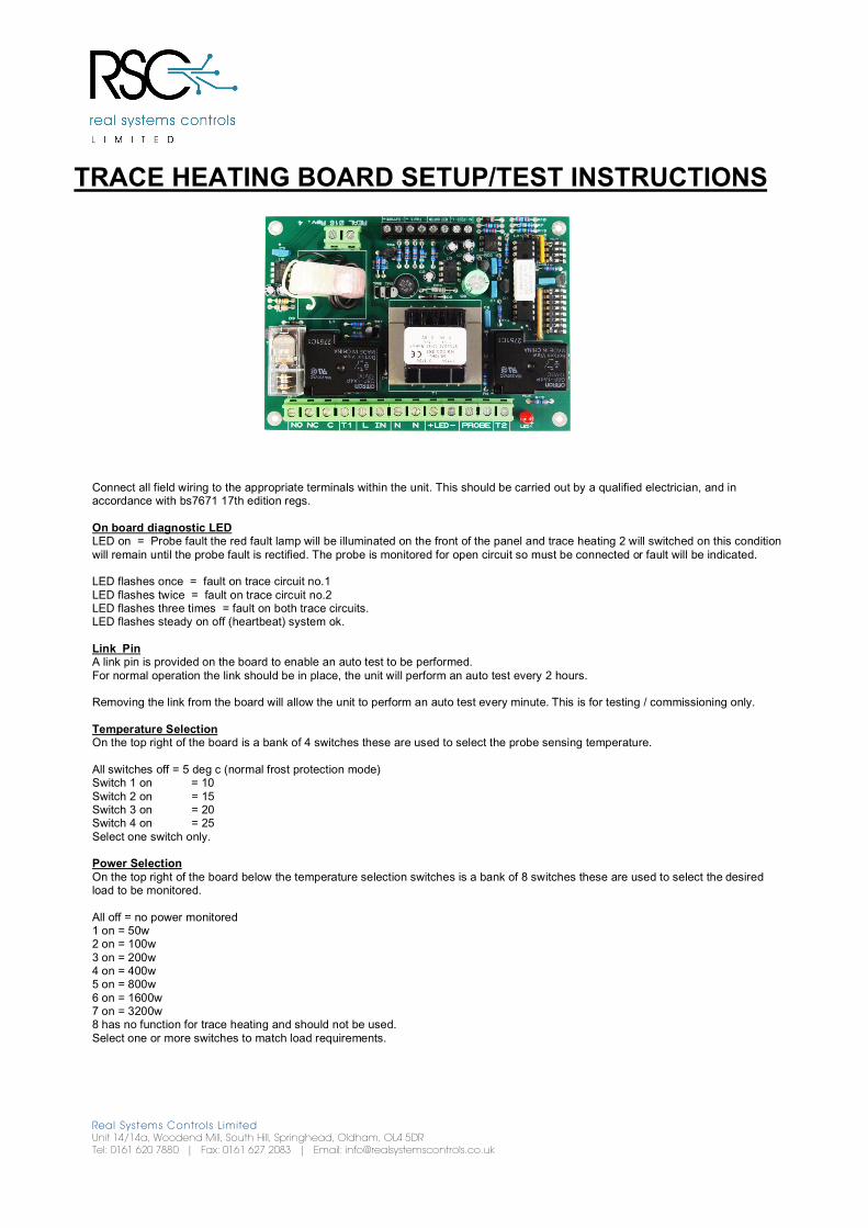
Connect all field wiring to the appropriate terminals within the unit. This should be carried out by a qualified electrician, and in accordance with bs7671 17th edition regs. On board diagnostic LED LED on = Probe fault the red fault lamp will be illuminated on the front of the panel and trace heating 2 will switched on this condition will remain until the probe fault is rectified. The probe is monitored for open circuit so must be connected or fault will be indicated. LED flashes once = fault on trace circuit no.1 LED flashes twice = fault on trace circuit no.2 LED flashes three times = fault on both trace circuits. LED flashes steady on off (heartbeat) system ok. Link Pin A link pin is provided on the board to enable an auto test to be performed. For normal operation the link should be in place, the unit will perform an auto test every 2 hours. Removing the link from the board will allow the unit to perform an auto test every minute. This is for testing / commissioning only. Temperature Selection On the top right of the board is a bank of 4 switches these are used to select the probe sensing temperature. All switches off = 5 deg c (normal frost protection mode) Switch 1 on = 10 Switch 2 on = 15 Switch 3 on = 20 Switch 4 on = 25 Select one switch only. Power Selection On the top right of the board below the temperature selection switches is a bank of 8 switches these are used to select the desired load to be monitored. All off = no power monitored 1 on = 50w 2 on = 100w 3 on = 200w 4 on = 400w 5 on = 800w 6 on = 1600w 7 on = 3200w 8 has no function for trace heating and should not be used. Select one or more switches to match load requirements.