town of warrenton wastewater treatment plant …
TRANSCRIPT
September 21, 2018 Addendum No. 2 Town of Warrenton Wastewater Treatment
Plant Moving Bed Bioreactor (MBBR) Installation IFB #19-002
TOWN OF WARRENTON
WASTEWATER TREATMENT PLANT
MOVING BED BIOREACTOR (MBBR) INSTALLATION
IFB # 19-002
ADDENDUM #2
September 21, 2018
To All Bidders:
Bidders submitting for the above-named project shall take note of the following changes,
additions, deletions, clarifications, etc., in the Contract Documents, which shall become a part of
and have precedence over anything shown or described in the Contract Documents, and as such
shall be taken into consideration and be included in the Bid. All other terms and conditions shall
remain the same.
Bidder shall acknowledge receipt of this Addendum No. 2 on the Bid Form as attached
hereto (the following page).
The Bid Closing Date is September 27, 2018 at 2:00 pm.
Submit the Certification Page with revised Bid Closing Date as attached hereto.
Any other references in the Bid Documents to Bid Closing Date shall be September 27,
2018 at 2:00 PM
Page 1 of 26
September 21, 2018 Addendum No. 2 Town of Warrenton Wastewater Treatment
Plant Moving Bed Bioreactor (MBBR) Installation IFB #19-002
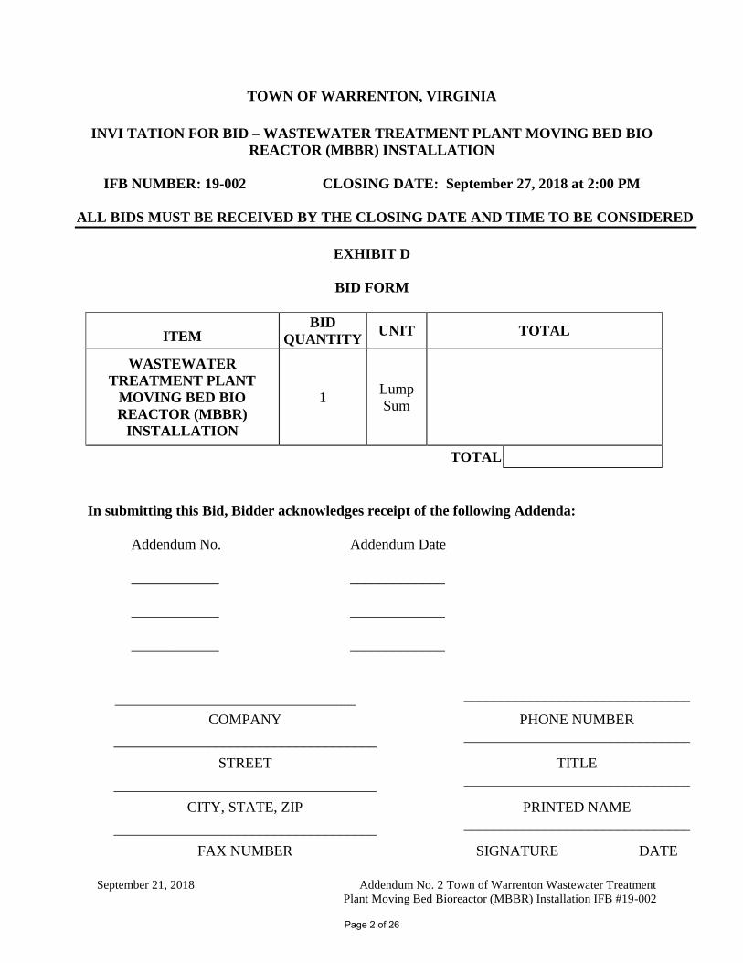
TOWN OF WARRENTON, VIRGINIA
INVI TATION FOR BID – WASTEWATER TREATMENT PLANT MOVING BED BIO
REACTOR (MBBR) INSTALLATION
IFB NUMBER: 19-002 CLOSING DATE: September 27, 2018 at 2:00 PM
ALL BIDS MUST BE RECEIVED BY THE CLOSING DATE AND TIME TO BE CONSIDERED
EXHIBIT D
BID FORM
ITEM BID
QUANTITY UNIT TOTAL
WASTEWATER
TREATMENT PLANT
MOVING BED BIO
REACTOR (MBBR)
INSTALLATION
1 Lump
Sum
TOTAL
In submitting this Bid, Bidder acknowledges receipt of the following Addenda:
Addendum No. Addendum Date
____________ _____________
____________ _____________
____________ _____________
_________________________________
_______________________________
_____ COMPANY
PHONE NUMBER
____________________________________
_______________________________
____ STREET
TITLE
____________________________________
_______________________________
____ CITY, STATE, ZIP
PRINTED NAME
____________________________________
_______________________________
____ FAX NUMBER
SIGNATURE DATE
Page 2 of 26
September 21, 2018 Addendum No. 2 Town of Warrenton Wastewater Treatment
Plant Moving Bed Bioreactor (MBBR) Installation IFB #19-002
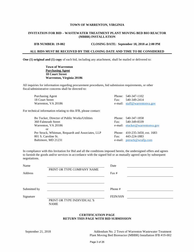
TOWN OF WARRENTON, VIRGINIA
INVITATION FOR BID – WASTEWATER TREATMENT PLANT MOVING BED BIO REACTOR
(MBBR) INSTALLATION
IFB NUMBER: 19-002 CLOSING DATE: September 18, 2018 at 2:00 PM
ALL BIDS MUST BE RECEIVED BY THE CLOSING DATE AND TIME TO BE CONSIDERED
One (1) original and (1) copy of each bid, including any attachment, shall be mailed or delivered to:
Town of Warrenton
Purchasing Agent
18 Court Street
Warrenton, Virginia 20186
All inquiries for information regarding procurement procedures, bid submission requirements, or other
fiscal/administrative concerns shall be directed to:
Purchasing Agent Phone: 540-347-1102
18 Court Street Fax: 540-349-2414
Warrenton, VA 20186 e-mail: [email protected]
For technical information relating to this IFB, please contact:
Bo Tucker, Director of Public Works/Utilities Phone: 540-347-1858
360 Falmouth Street Fax: 540-349-8339
Warrenton, VA 20186 e-mail: [email protected]
or
Per Struck, Whitman, Requardt and Associates, LLP Phone: 410-235-3450, ext. 1683
801 S. Caroline St. Fax: 443-224-1883
Baltimore, MD 21231 e-mail: [email protected]
In compliance with this Invitation for Bid and all the conditions imposed herein, the undersigned offers and agrees
to furnish the goods and/or services in accordance with the signed bid or as mutually agreed upon by subsequent
negotiations.
Name Date
PRINT OR TYPE COMPANY NAME
Address Fax #
Submitted by Phone #
Signature FEIN/SSN
PRINT OR TYPE INDIVIDUAL’S
NAME
CERTIFICATION PAGE
RETURN THIS PAGE WITH BID SUBMISSION
Page 3 of 26
September 21, 2018 Addendum No. 2 Town of Warrenton Wastewater Treatment
Plant Moving Bed Bioreactor (MBBR) Installation IFB #19-002
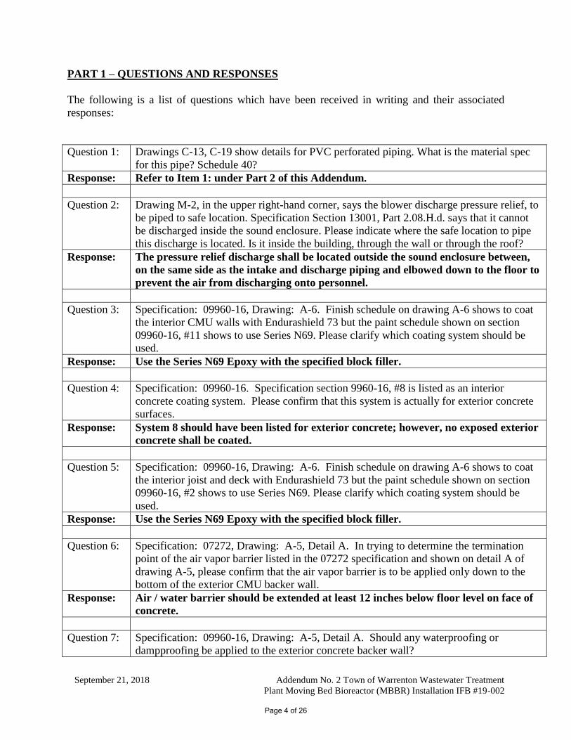
PART 1 – QUESTIONS AND RESPONSES
The following is a list of questions which have been received in writing and their associated
responses:
Question 1: : Drawings C-13, C-19 show details for PVC perforated piping. What is the material spec
for this pipe? Schedule 40?
Response: Refer to Item 1: under Part 2 of this Addendum.
Question 2: : Drawing M-2, in the upper right-hand corner, says the blower discharge pressure relief, to
be piped to safe location. Specification Section 13001, Part 2.08.H.d. says that it cannot
be discharged inside the sound enclosure. Please indicate where the safe location to pipe
this discharge is located. Is it inside the building, through the wall or through the roof?
Response: The pressure relief discharge shall be located outside the sound enclosure between,
on the same side as the intake and discharge piping and elbowed down to the floor to
prevent the air from discharging onto personnel.
Question 3: : Specification: 09960-16, Drawing: A-6. Finish schedule on drawing A-6 shows to coat
the interior CMU walls with Endurashield 73 but the paint schedule shown on section
09960-16, #11 shows to use Series N69. Please clarify which coating system should be
used.
Response: Use the Series N69 Epoxy with the specified block filler.
Question 4: : Specification: 09960-16. Specification section 9960-16, #8 is listed as an interior
concrete coating system. Please confirm that this system is actually for exterior concrete
surfaces.
Response: System 8 should have been listed for exterior concrete; however, no exposed exterior
concrete shall be coated.
Question 5: : Specification: 09960-16, Drawing: A-6. Finish schedule on drawing A-6 shows to coat
the interior joist and deck with Endurashield 73 but the paint schedule shown on section
09960-16, #2 shows to use Series N69. Please clarify which coating system should be
used.
Response: Use the Series N69 Epoxy with the specified block filler.
Question 6: : Specification: 07272, Drawing: A-5, Detail A. In trying to determine the termination
point of the air vapor barrier listed in the 07272 specification and shown on detail A of
drawing A-5, please confirm that the air vapor barrier is to be applied only down to the
bottom of the exterior CMU backer wall.
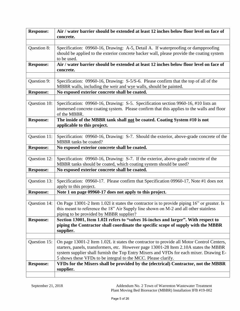
Response: Air / water barrier should be extended at least 12 inches below floor level on face of
concrete.
Question 7: : Specification: 09960-16, Drawing: A-5, Detail A. Should any waterproofing or
dampproofing be applied to the exterior concrete backer wall?
Page 4 of 26
September 21, 2018 Addendum No. 2 Town of Warrenton Wastewater Treatment
Plant Moving Bed Bioreactor (MBBR) Installation IFB #19-002
Response: Air / water barrier should be extended at least 12 inches below floor level on face of
concrete.
Question 8: : Specification: 09960-16, Drawing: A-5, Detail A. If waterproofing or dampproofing
should be applied to the exterior concrete backer wall, please provide the coating system
to be used.
Response: Air / water barrier should be extended at least 12 inches below floor level on face of
concrete.
Question 9: : Specification: 09960-16, Drawing: S-5/S-6. Please confirm that the top of all of the
MBBR walls, including the weir and wye walls, should be painted.
Response: No exposed exterior concrete shall be coated.
Question 10: : Specification: 09960-16, Drawing: S-5. Specification section 9960-16, #10 lists an
immersed concrete coating system. Please confirm that this applies to the walls and floor
of the MBBR.
Response: The inside of the MBBR tank shall not be coated. Coating System #10 is not
applicable to this project.
Question 11: : Specification: 09960-16, Drawing: S-7. Should the exterior, above-grade concrete of the
MBBR tanks be coated?
Response: No exposed exterior concrete shall be coated.
Question 12: : Specification: 09960-16, Drawing: S-7. If the exterior, above-grade concrete of the
MBBR tanks should be coated, which coating system should be used?
Response: No exposed exterior concrete shall be coated.
Question 13: : Specification: 09960-17. Please confirm that Specification 09960-17, Note #1 does not
apply to this project.
Response: Note 1 on page 09960-17 does not apply to this project.
Question 14: : On Page 13001-2 Item 1.02I it states the contractor is to provide piping 16” or greater. Is
this meant to reference the 18” Air Supply line shown on M-2 and all other stainless
piping to be provided by MBBR supplier?
Response: Section 13001, Item 1.02I refers to “valves 16-inches and larger”. With respect to
piping the Contractor shall coordinate the specific scope of supply with the MBBR
supplier.
Question 15: : On page 13001-2 Item 1.02L it states the contractor to provide all Motor Control Centers,
starters, panels, transformers, etc. However page 13001-28 Item 2.10A states the MBBR
system supplier shall furnish the Top Entry Mixers and VFDs for each mixer. Drawing E-
5 shows these VFDs to be integral to the MCC. Please clarify.
Response: VFDs for the Mixers shall be provided by the (electrical) Contractor, not the MBBR
supplier.
Page 5 of 26
September 21, 2018 Addendum No. 2 Town of Warrenton Wastewater Treatment
Plant Moving Bed Bioreactor (MBBR) Installation IFB #19-002
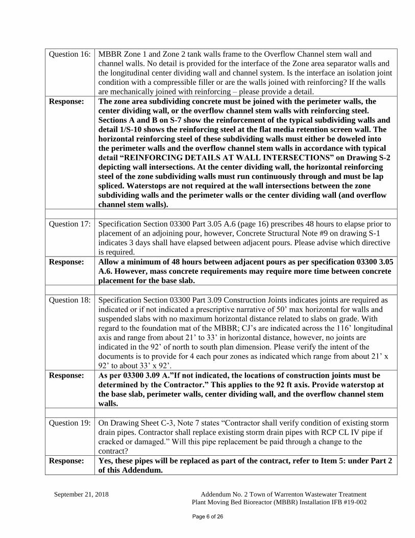
Question 16: : MBBR Zone 1 and Zone 2 tank walls frame to the Overflow Channel stem wall and
channel walls. No detail is provided for the interface of the Zone area separator walls and
the longitudinal center dividing wall and channel system. Is the interface an isolation joint
condition with a compressible filler or are the walls joined with reinforcing? If the walls
are mechanically joined with reinforcing – please provide a detail.
Response: The zone area subdividing concrete must be joined with the perimeter walls, the
center dividing wall, or the overflow channel stem walls with reinforcing steel.
Sections A and B on S-7 show the reinforcement of the typical subdividing walls and
detail 1/S-10 shows the reinforcing steel at the flat media retention screen wall. The
horizontal reinforcing steel of these subdividing walls must either be doweled into
the perimeter walls and the overflow channel stem walls in accordance with typical
detail “REINFORCING DETAILS AT WALL INTERSECTIONS” on Drawing S-2
depicting wall intersections. At the center dividing wall, the horizontal reinforcing
steel of the zone subdividing walls must run continuously through and must be lap
spliced. Waterstops are not required at the wall intersections between the zone
subdividing walls and the perimeter walls or the center dividing wall (and overflow
channel stem walls).
Question 17: : Specification Section 03300 Part 3.05 A.6 (page 16) prescribes 48 hours to elapse prior to
placement of an adjoining pour, however, Concrete Structural Note #9 on drawing S-1
indicates 3 days shall have elapsed between adjacent pours. Please advise which directive
is required.
Response: Allow a minimum of 48 hours between adjacent pours as per specification 03300 3.05
A.6. However, mass concrete requirements may require more time between concrete
placement for the base slab.
Question 18: : Specification Section 03300 Part 3.09 Construction Joints indicates joints are required as
indicated or if not indicated a prescriptive narrative of 50’ max horizontal for walls and
suspended slabs with no maximum horizontal distance related to slabs on grade. With
regard to the foundation mat of the MBBR; CJ’s are indicated across the 116’ longitudinal
axis and range from about 21’ to 33’ in horizontal distance, however, no joints are
indicated in the 92’ of north to south plan dimension. Please verify the intent of the
documents is to provide for 4 each pour zones as indicated which range from about 21’ x
92’ to about 33’ x 92’.
Response: As per 03300 3.09 A.”If not indicated, the locations of construction joints must be
determined by the Contractor.” This applies to the 92 ft axis. Provide waterstop at
the base slab, perimeter walls, center dividing wall, and the overflow channel stem
walls.
Question 19: : On Drawing Sheet C-3, Note 7 states “Contractor shall verify condition of existing storm
drain pipes. Contractor shall replace existing storm drain pipes with RCP CL IV pipe if
cracked or damaged.” Will this pipe replacement be paid through a change to the
contract?
Response: Yes, these pipes will be replaced as part of the contract, refer to Item 5: under Part 2
of this Addendum.
Page 6 of 26
September 21, 2018 Addendum No. 2 Town of Warrenton Wastewater Treatment
Plant Moving Bed Bioreactor (MBBR) Installation IFB #19-002
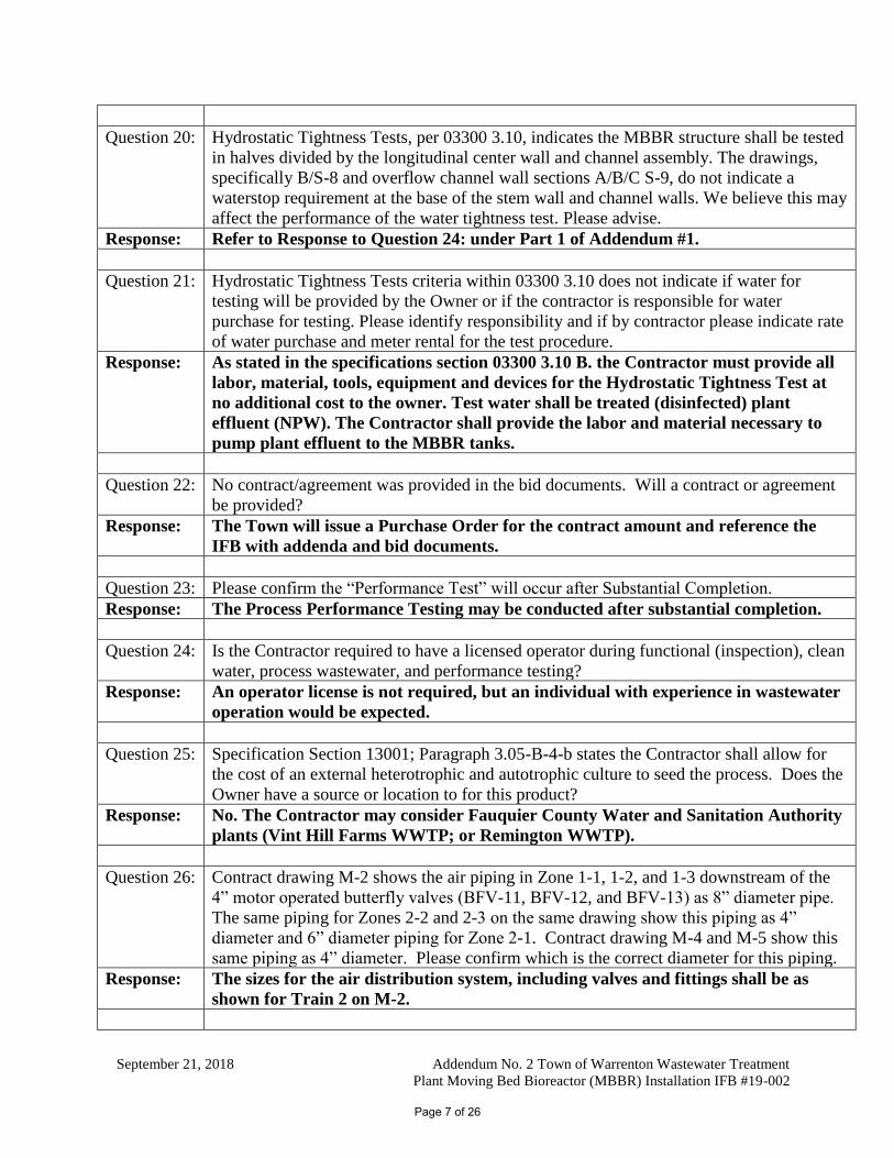
Question 20: : Hydrostatic Tightness Tests, per 03300 3.10, indicates the MBBR structure shall be tested
in halves divided by the longitudinal center wall and channel assembly. The drawings,
specifically B/S-8 and overflow channel wall sections A/B/C S-9, do not indicate a
waterstop requirement at the base of the stem wall and channel walls. We believe this may
affect the performance of the water tightness test. Please advise.
Response: Refer to Response to Question 24: under Part 1 of Addendum #1.
Question 21: : Hydrostatic Tightness Tests criteria within 03300 3.10 does not indicate if water for
testing will be provided by the Owner or if the contractor is responsible for water
purchase for testing. Please identify responsibility and if by contractor please indicate rate
of water purchase and meter rental for the test procedure.
Response: As stated in the specifications section 03300 3.10 B. the Contractor must provide all
labor, material, tools, equipment and devices for the Hydrostatic Tightness Test at
no additional cost to the owner. Test water shall be treated (disinfected) plant
effluent (NPW). The Contractor shall provide the labor and material necessary to
pump plant effluent to the MBBR tanks.
Question 22: : No contract/agreement was provided in the bid documents. Will a contract or agreement
be provided?
Response: The Town will issue a Purchase Order for the contract amount and reference the
IFB with addenda and bid documents.
Question 23: : Please confirm the “Performance Test” will occur after Substantial Completion.
Response: The Process Performance Testing may be conducted after substantial completion.
Question 24: : Is the Contractor required to have a licensed operator during functional (inspection), clean
water, process wastewater, and performance testing?
Response: An operator license is not required, but an individual with experience in wastewater
operation would be expected.
Question 25: : Specification Section 13001; Paragraph 3.05-B-4-b states the Contractor shall allow for
the cost of an external heterotrophic and autotrophic culture to seed the process. Does the
Owner have a source or location to for this product?
Response: No. The Contractor may consider Fauquier County Water and Sanitation Authority
plants (Vint Hill Farms WWTP; or Remington WWTP).
Question 26: : Contract drawing M-2 shows the air piping in Zone 1-1, 1-2, and 1-3 downstream of the
4” motor operated butterfly valves (BFV-11, BFV-12, and BFV-13) as 8” diameter pipe.
The same piping for Zones 2-2 and 2-3 on the same drawing show this piping as 4”
diameter and 6” diameter piping for Zone 2-1. Contract drawing M-4 and M-5 show this
same piping as 4” diameter. Please confirm which is the correct diameter for this piping.
Response: The sizes for the air distribution system, including valves and fittings shall be as
shown for Train 2 on M-2.
Page 7 of 26
September 21, 2018 Addendum No. 2 Town of Warrenton Wastewater Treatment
Plant Moving Bed Bioreactor (MBBR) Installation IFB #19-002
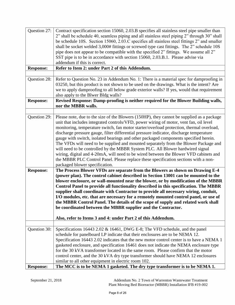
Question 27: : Contract specification section 15060, 2.03.B specifies all stainless steel pipe smaller than
2” shall be schedule 40, seamless piping and all stainless steel piping 2” through 30” shall
be schedule 10S. Section 15060, 2.03.C specifies all stainless steel fittings 2” and smaller
shall be socket welded 3,000# fittings or screwed type cast fittings. The 2” schedule 10S
pipe does not appear to be compatible with the specified 2” fittings. We assume all 2”
SST pipe is to be in accordance with section 15060, 2.03.B.1. Please advise via
addendum if this is correct.
Response: Refer to Item 2: under Part 2 of this Addendum.
Question 28: : Refer to Question No. 23 in Addendum No. 1: There is a material spec for damproofing in
03250, but this product is not shown to be used on the drawings. What is the intent? Are
we to apply damproofing to all below grade exterior walls? If yes, would that requirement
also apply to the Blwer Bldg walls?
Response: Revised Response: Damp-proofing is neither required for the Blower Building walls,
nor the MBBR walls.
Question 29: : Please note, due to the size of the Blowers (150HP), they cannot be supplied as a package
unit that includes integrated controls/VFD, power wiring of motor, vent fan, oil level
monitoring, temperature switch, fan motor starter/overload protection, thermal overload,
discharge pressure gauge, filter differential pressure indicator, discharge temperature
gauge with switch, isolated bearings and other packaged components specified herein.
The VFDs will need to be supplied and mounted separately from the Blower Package and
will need to be controlled by the MBBR System PLC. All Blower hardwired signal
wiring, digital and 4-20mA, will need to be wired between the Blower VFD cabinets and
the MBBR PLC Control Panel. Please replace these specification sections with a non-
packaged blower specification.
Response: The Process Blower VFDs are separate from the Blowers as shown on Drawing E-4
(power plan). The control cabinet described in Section 13001 can be mounted to the
blower enclosure, or wall-mounted near the blower, or by modification of the MBBR
Control Panel to provide all functionality described in this specification. The MBBR
supplier shall coordinate with Contractor to provide all necessary wiring, conduit,
I/O modules, etc. that are necessary for a remotely mounted control panel, or use of
the MBBR Control Panel. The details of the scope of supply and related work shall
be coordinated between the MBBR supplier and the Contractor.
Also, refer to Items 3 and 4: under Part 2 of this Addendum.
Question 30: : Specifications 16443 2.02 & 16461, DWG E-8; The VFD schedule, and the panel
schedule for panelboard LP indicate that their enclosures are to be NEMA 12.
Specification 16443 2.02 indicates that the new motor control center is to have a NEMA 1
gasketed enclosure, and specification 16461 does not indicate the NEMA enclosure type
for the 30 kVA transformer located in the same room. Please confirm that the motor
control center, and the 30 kVA dry type transformer should have NEMA 12 enclosures
similar to all other equipment in electric room 102.
Response: The MCC is to be NEMA 1 gasketed. The dry type transformer is to be NEMA 1.
Page 8 of 26
September 21, 2018 Addendum No. 2 Town of Warrenton Wastewater Treatment
Plant Moving Bed Bioreactor (MBBR) Installation IFB #19-002
Question 31: : DWG E-2; Drawing Note 9 indicated on drawing sheet E-2 next to Marshalling Panel
MP-202 indicates pulling new wiring from Marshalling Panel MP-201 to the annunciator
panel in the Plant Control building through an existing buried conduit. Please confirm the
intent of this note is to install the new conductors from the new Marshalling panel MP-
201 through Marshalling Panel MP-202 to the annunciator located in the Plant Control
building. Please also provide the location of the Plant Control building and confirm that
the existing buried conduit terminates in the annunciator panel and that additional conduit
will not be required.
Response: The intent is to have new wire routed from Marshalling Panel MP-201 to MP-202,
then have new wire routed from MP-202 to Plant Control Building via an existing
buried conduit. The junction box to the existing conduit is located at the south-west
corner of the existing RBC Blower Building near the existing MCC. Location of
Existing Plant Control Building is shown on Contract Drawing C-1.
Question 32: : DWG E-2; Please confirm that Marshalling panel MP-202 located in the existing RBC
Blower building on drawing sheet E-2 is existing.
Response: Marshalling Panel, MP-202, is not existing and shall be provided by the Contractor.
Question 33: : DWG E-2; Drawing Note 5 on drawing sheet E-2 indicates that all permanent wiring and
electrical devices associated with the RBC system equipment abandoned in place shall be
tagged or identified as abandoned. Please provide demolition drawings, or a one-line for
MCC1 indicating what equipment is to be made safe and abandoned and tagged.
Response: There are 21 RBC Unit, NEMA Size 1 motor starters in existing MCC1 that are to
be left in place and turned into and tagged as spare motor starters.
Question 34: : DWG E-3; Drawing sheet E-3 indicates Drawing Note 2 at the (2) WP three way
switches controlling the light fixtures at the MBBR tanks. Drawing Note 2 indicates
providing a 24"x24"x12" NEMA 4X stainless steel enclosure. Please confirm that these
switches should have Drawing Note 1 next to them, and that Drawing Note 2 should be
removed.
Response: The switches should have Drawing Note 1 next to them in-lieu of Drawing Note 2.
Question 35: : DWG E-3; Drawing sheet E-3 indicates Drawing Note 2 at the power wiring pull box and
the Marshalling panel. Drawing Note 2 indicates providing a 24"x24"x12" NEMA 4X
stainless steel enclosure. Please confirm that Drawing Note 2 should be removed from
the Marshalling panel as it will be furnished by others.
Response: The Marshalling Panel and its contents are to be furnished by the Contractor’s CSI
per Division 17 of the Specifications.
Question 36: : DWG E-3; There is no Drawing Note 7 on drawing sheet E-3. Please confirm that
Drawing Note 7 should be removed.
Response: The conduits do not terminate in the bottom of the pullbox and panel as indicated.
Rather the conduits enter the pullbox and panel as indicated in Drawing Note 7.
Refer to Item 6: under Part 2 of this Addendum.
Page 9 of 26
September 21, 2018 Addendum No. 2 Town of Warrenton Wastewater Treatment
Plant Moving Bed Bioreactor (MBBR) Installation IFB #19-002
Question 37: : DWG E-5; Please provide the manufacturer make and model of existing distribution
switchboard SB indicated on drawing sheet E-5.
Response: The existing distribution switchboard is a Square D Type QED.
Question 38: : DWG E-5; The single line diagram on drawing sheet E-5 indicates motor starters for the
slide weir gates, mono rail hoist, and the motorized butterfly valves. These starters are
not shown on the floor plan drawings. Please confirm these starters are integral to the
equipment, and that the division 16 contractor will only be required to provide the local
disconnect switches indicated on the single line diagram and floor plan drawings.
Response: The starters are integral to the equipment.
Question 39: : DWG D-1; Drawing sheet C-1 indicates the relocation of an existing light pole. Please
provide a pole base detail for the light pole to be relocated indicating the requirements for
concrete, rebar, anchor bolts and the approximate height of the light pole.
Response: The light pole foundation shall conform to the latest VDOT Standard Detail LF-1,
Lighting Pole Foundation Installation Details.
PART 2 – CHANGES TO THE CONTRACT DOCUMENTS
The following are changes to the Contract Documents hereby incorporated via this Addendum
No. 2.
SPECIFICATIONS:
Item 1: In Exhibit A – Specifications Table of Contents
Division 2 – Site Work: ADD:
“02620 – Subdrainage”
“02630 – Storm Drainage”
The 02620 – Subdrainage specification is included in Attachment “A” as part of this
Addendum.
The 02630 – Storm Drainage specification is included in Attachment “B” as part of this
Addendum.
Item 2: In Section 15060 PART 2
2.03 B 2:
DELETE “smaller than 2-inches” and ADD “2-inches and smaller”
Page 10 of 26
September 21, 2018 Addendum No. 2 Town of Warrenton Wastewater Treatment
Plant Moving Bed Bioreactor (MBBR) Installation IFB #19-002
Item 3: In Section 13001:
In Paragraph 2.08.A, at the of the paragraph, last sentence, REVISE with the following
manufacturers: “Kaeser Compressors, Inc.; Howden Group; Gardner Denver Inc.; and
Aerzen Corporation.”
In Paragraph 2.09.E.1, REPLACE the paragraph with the following:
“1. The control cabinet described in this section can be mounted to the blower enclosure,
or wall-mounted near the blower, or by modification of the MBBR Control Panel to
provide all functionality described in this specification. The MBBR Supplier shall
coordinate with Contractor to provide all necessary wiring, conduit, I/O modules, etc. that
are necessary for a remotely mounted control panel, or use of the MBBR Control Panel.
The details of the scope of supply and related work shall be coordinated between the
MBBR supplier and the Contractor.”
Item 4: It is the intent for the MBBR Supplier to provide the VFDs for the Process Blowers as
originally stated under Section 13001, Part 2.09.G (therefore, disregard any revisions to
this Part 2.09.G in Addendum No. 1).
DRAWINGS:
Item 5: On Drawing C-3:
DELETE NOTE #7 in its entirety, and REPLACE with:
“7. ALL STORM DRAIN SEWERS SHALL BE RCP CLASS IV WITH A MINIMUM
COVER OF 9-INCHES, UNLESS OTHERWISE INDICATED. CONTRACTOR
SHALL REPLACE STORM DRAIN PIPES AND PROTECT THEM DURING SITE
CONSTRUCTION ACTIVITIES. AT THE END OF CONSTRUCTION, THE
CONTRACTOR SHALL CCTV INSPECT THE STORM DRAIN PIPES FOR
DAMAGES. ANY DAMAGED PIPE SHALL BE REPLACED AT NO ADDITIONAL
COST TO THE OWNER.”
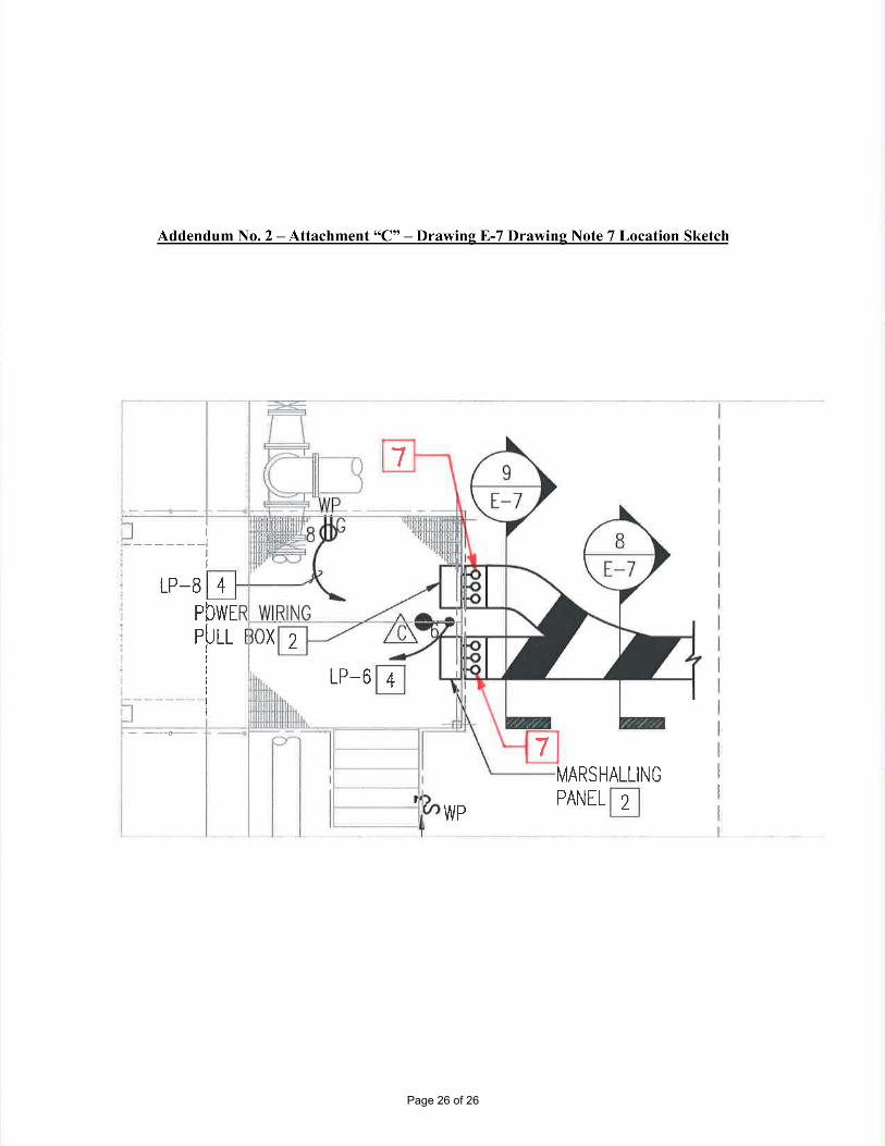
Item 6: On Drawing E-3:
Drawing Note #2: DELETE the second sentence in its entirety.
Plan View: ADD two Note #7 bubble leader annotations as shown in Attachment “C” as
part of this addendum.
Page 11 of 26
Wastewater Treatment Plant MBBR Installation Storm Drainage
Town of Warrenton, VA
N:\18544-000\Engineering\Adv_Bid\Addenda\Addendum #2\02630 - Storm Drainage.DOC September 2018
02630-1 (Addendum #2 9-21-2018)
Addendum No. 2 – Attachment “A” – Specification Section 02630
SECTION 02630
STORM DRAINAGE
PART 1 - GENERAL
1.01. DESCRIPTION
A. Construction of stormwater conveyance systems including pipelines and structures
intended to carry runoff by gravity. This includes storm drain culverts, underdrain
piping, storm drain sewer, and storm sewer inlet and discharge structures. Locations
and details of construction are shown on the drawings. Provide work under this Section
as shown or specified and in accordance with the requirements of the Contract
Documents.
1.02. Documents affecting work of this Section include, but are not necessarily limited to:
Section 02200, “Earthwork, Excavation, Trenching and Backfilling”.
Section 02620, “Subdrainage”
1.03. QUALITY ASSURANCE
A. Piping materials shall bear label, stamp, or other markings of specified testing agency.
B. Workmanship
Use only fully trained and skilled workers under direction of an experienced foreman.
Construct the work in a substantial and workmanlike manner. Provide only new, first
class material as may be necessary to complete the installation in accordance with the
best trade practice and to the satisfaction of the Engineer.
C. Applicable Standards
The following publications will govern the work covered by this Section of the extent
applicable. In event of a conflict between this Section and any referenced publication,
the more stringent requirement will apply.
1. The Virginia Department of Transportation: Drainage Manual, latest edition.
Page 12 of 26
Wastewater Treatment Plant MBBR Installation Storm Drainage
Town of Warrenton, VA
N:\18544-000\Engineering\Adv_Bid\Addenda\Addendum #2\02630 - Storm Drainage.DOC September 2018
02630-2 (Addendum #2 9-21-2018)
2. Virginia Department of Transportation: Road and Bridge Specifications, latest
edition.
3. Virginia Department of Transportation: Road and Bridge Standards, latest edition.
4. Virginia Department of Environmental Quality: Virginia Erosion and Sediment
Control Handbook, latest edition.
5. Town of Warrenton: Public Facilities Manual, latest edition.
6. Applicable ASTM Standards, latest revision.
1.04. DELIVERY, STORAGE, AND HANDLING
A. Do not store plastic manholes, pipe, and fittings in direct sunlight.
B. Protect pipe, pipe fittings, and seals from dirt and damage.
C. Handle manholes in accordance with manufacturer's written rigging instructions.
D. Handle catch basins, end sections, and stormwater inlets in accordance with
manufacturer's written rigging instructions.
E. Unload pipe and appurtenances so as to avoid deformation or injury thereto. Pipes shall
not be placed within pipe of a larger size nor rolled or dragged over gravel or rock
during handling. Store pipe on sills above storm drainage level and deliver for laying
after the trench is excavated. When any joint or section of pipe is damaged during
transporting, unloading, handling or storing, the undamaged portions of the joint or
section may be used where partial lengths are needed. In all cases, the Inspector may
reject the joint or section as being unfit for installation. Any defective pipe or
appurtenances discovered after installation shall be removed immediately and replaced
with sound material or repaired to the satisfaction of the Engineer.
PART 2 - PRODUCTS
2.01. PVC PIPE AND FITTINGS
A. Source Limitations: Obtain PVC pipe and fittings from single manufacturer.
B. NSF Marking: Comply with NSF 14, "Plastics Piping Systems Components and Related
Materials," for plastic piping components. Include marking with "NSF-drain" for plastic
storm drain and "NSF-sewer" for plastic storm sewer piping.
C. PVC Type PSM Sewer Piping:
Page 13 of 26
Wastewater Treatment Plant MBBR Installation Storm Drainage
Town of Warrenton, VA
N:\18544-000\Engineering\Adv_Bid\Addenda\Addendum #2\02630 - Storm Drainage.DOC September 2018
02630-3 (Addendum #2 9-21-2018)
1. Pipe: ASTM D3034, SDR 35, PVC Type PSM sewer pipe with bell-and-spigot
ends for gasketed joints.
2. Fittings: ASTM D3034, PVC with bell ends.
3. Gaskets: ASTM F477, elastomeric seals.
2.02. CONCRETE PIPE AND FITTINGS
A. Source Limitations: Obtain concrete pipe and fittings from single manufacturer.
B. Reinforced-Concrete Sewer Pipe and Fittings: ASTM C-76 or AASHTO M170.
1. Bell-and-spigot ends and gasketed joints with ASTM C443, rubber gaskets.
2. Class IV, Wall B.
2.03. CLEANOUTS
A. Cast-Iron Cleanouts:
1. Source Limitations: Obtain cast-iron cleanouts from single manufacturer.
2. Description: ASME A112.36.2M, round, gray-iron housing with clamping device
and round, secured, scoriated, gray-iron cover. Include gray-iron ferrule with
inside caulk or spigot connection and countersunk, tapered-thread, brass closure
plug.
3. Top-Loading Classification(s): Medium Duty.
4. Sewer Pipe Fitting and Riser to Cleanout: ASTM A74, Service class, cast-iron
soil pipe and fittings.
B. PVC Cleanouts:
1. Source Limitations: Obtain PVC cleanouts from single manufacturer.
2. Description: PVC body with PVC threaded plug. Include PVC sewer pipe fitting
and riser to cleanout of same material as sewer piping.
2.04. CONCRETE
A. General: Cast-in-place concrete in accordance with ACI 318, ACI 350, and the
following:
1. Cement: ASTM C150/C150M, Type II.
2. Fine Aggregate: ASTM C33/C33M, sand.
3. Coarse Aggregate: ASTM C33/C33M, crushed gravel.
4. Water: Potable.
B. Portland Cement Design Mix: 4000 psi minimum, with 0.45 maximum
water/cementitious materials ratio.
1. Reinforcing Fabric: ASTM A1064/A1064M, steel, welded wire fabric, plain.
Page 14 of 26
Wastewater Treatment Plant MBBR Installation Storm Drainage
Town of Warrenton, VA
N:\18544-000\Engineering\Adv_Bid\Addenda\Addendum #2\02630 - Storm Drainage.DOC September 2018
02630-4 (Addendum #2 9-21-2018)
2. Reinforcing Bars: ASTM A615/A615M, Grade 60 (420 MPa) deformed steel.
C. Manhole Channels and Benches: Factory or field formed from concrete. Portland
cement design mix, 4000 psi minimum, with 0.45 maximum water/cementitious
materials ratio. Include channels and benches in manholes.
1. Channels: Concrete invert, formed to same width as connected piping, with height
of vertical sides to three-fourths of pipe diameter. Form curved channels with
smooth, uniform radius and slope.
a. Invert Slope: 2 percent through manhole.
2. Benches: Concrete, sloped to drain into channel.
a. Slope: 8 percent.
D. Ballast and Pipe Supports: Portland cement design mix, 3000 psi minimum, with 0.58
maximum water/cementitious materials ratio.
1. Reinforcing Fabric: ASTM A1064/A1064M, steel, welded wire fabric, plain.
2. Reinforcing Bars: ASTM A615/A615M, Grade 60 (420 MPa) deformed steel.
2.05. CATCH BASINS
A. Designed Precast Concrete Catch Basins: ASTM C913, precast, reinforced concrete;
designed in accordance with ASTM C890 for A-16 (ASSHTO HS20-44), heavy-traffic,
structural loading; of depth, shape, and dimensions indicated, with provision for joint
sealants.
1. Joint Sealants: ASTM C990, bitumen or butyl rubber.
2. Steps: Individual FRP steps or FRP ladder, wide enough to allow worker to place
both feet on one step and designed to prevent lateral slippage off step. Cast or
anchor steps into sidewalls at 12- to 16-inch intervals. Omit steps if total depth
from floor of catch basin to finished grade is less than 48 inches.
3. Pipe Connectors: ASTM C923, resilient, of size required, for each pipe
connecting to base section.
B. Frames and Grates: ASTM A536, Grade 60-40-18, ductile iron designed for A-16
(AASHTO HS20-44), structural loading. Include flat grate with small square or short-
slotted drainage openings.
1. Size: 30 by 30 inches minimum unless otherwise indicated.
2. Grate Free Area: Approximately 50 percent unless otherwise indicated.
Page 15 of 26
Wastewater Treatment Plant MBBR Installation Storm Drainage
Town of Warrenton, VA
N:\18544-000\Engineering\Adv_Bid\Addenda\Addendum #2\02630 - Storm Drainage.DOC September 2018
02630-5 (Addendum #2 9-21-2018)
2.06. PIPE OUTLETS
A. Riprap Basins: Broken, irregularly sized and shaped, graded stone in accordance with
VDOT Road and Bridge Standards.
1. VDOT: Class AI, Weight Range 25-75 lbs, maximum 10% greater than 75 lbs.
2. VDOT: Class I, Weight Range 50-150 lbs, maximum 60% greater than 100 lbs.
B. Soil Stabilization Mats: Soil stabilization blankets: In accordance with VDOT’s Road
and Bridge Specifications.
1. VDOT: EC-2, Type 4.
2. VDOT: EC-3, Type 1.
PART 3 - EXECUTION
3.01. EARTHWORK
A. Excavation, trenching, and backfilling are specified in Section 02200 “Earthwork.”
3.02. PIPING INSTALLATION
A. General Locations and Arrangements: Drawing plans and details indicate general
location and arrangement of underground storm drainage piping. Location and
arrangement of piping layout take into account design considerations. Install piping as
indicated, to extent practical. Where specific installation is not indicated, follow piping
manufacturer's written instructions.
B. Install piping beginning at low point, true to grades and alignment indicated with
unbroken continuity of invert. Place bell ends of piping facing upstream. Install gaskets,
seals, sleeves, and couplings in accordance with manufacturer's written instructions for
use of lubricants, cements, and other installation requirements.
C. Install gravity-flow, nonpressure drainage piping in accordance with the following:
1. Install piping pitched down in direction of flow.
2. Install PVC profile gravity sewer piping in accordance with ASTM D2321 and
ASTM F1668.
3. Install reinforced-concrete sewer piping in accordance with ASTM C1479 and
ACPA's "Concrete Pipe Installation Manual."
3.03. PIPE JOINT CONSTRUCTION
A. Join gravity-flow, nonpressure drainage piping in accordance with the following:
Page 16 of 26
Wastewater Treatment Plant MBBR Installation Storm Drainage
Town of Warrenton, VA
N:\18544-000\Engineering\Adv_Bid\Addenda\Addendum #2\02630 - Storm Drainage.DOC September 2018
02630-6 (Addendum #2 9-21-2018)
1. Join PVC profile gravity sewer piping in accordance with ASTM D2321 for
elastomeric-seal joints or ASTM F794 for gasketed joints.
2. Join reinforced-concrete sewer piping in accordance with ACPA's "Concrete Pipe
Installation Manual" for rubber-gasketed joints.
3.04. CLEANOUT INSTALLATION
A. Install cleanouts and riser extensions from sewer pipes to cleanouts at grade. Use cast-
iron soil pipe fittings in sewer pipes at branches for cleanouts and cast-iron soil pipe for
riser extensions to cleanouts. Install piping so cleanouts open in direction of flow in
sewer pipe.
1. Use Medium-Duty, top-loading classification cleanouts in paved foot-traffic
areas.
B. Set cleanout frames and covers in earth in cast-in-place concrete block, 30 by 30 by 10
inches deep. Set with tops 0 inch(es) above surrounding earth grade.
C. Set cleanout frames and covers in concrete pavement and roads with tops flush with
pavement surface.
3.05. STORMWATER INLET AND OUTLET INSTALLATION
A. Construct inlet head walls, aprons, and sides of reinforced concrete, as indicated.
B. Construct riprap of broken stone, as indicated.
C. Install outlets that spill onto grade with soil stabilization matting, anchored as indicated,
where indicated.
D. Install outlets that spill onto grade, with flared end sections that match pipe, where
indicated.
E. Construct energy dissipaters at outlets, as indicated.
3.06. CONCRETE PLACEMENT
A. Place cast-in-place concrete in accordance with ACI 318.
3.07. IDENTIFICATION
A. Materials and their installation are specified in Section 02200 “Earthwork.” Arrange for
installation of green warning tape directly over piping and at outside edge of
underground structures.
1. Use detectable warning tape over nonferrous piping and over edges of
underground structures.
Page 17 of 26
Wastewater Treatment Plant MBBR Installation Storm Drainage
Town of Warrenton, VA
N:\18544-000\Engineering\Adv_Bid\Addenda\Addendum #2\02630 - Storm Drainage.DOC September 2018
02630-7 (Addendum #2 9-21-2018)
3.08. FIELD QUALITY CONTROL
A. Inspect interior of piping to determine whether line displacement or other damage has
occurred. Inspect after approximately 24 inches of backfill is in place, and again at
completion of Project.
1. Submit separate reports for each system inspection.
2. Defects requiring correction include the following:
a. Alignment: Less than full diameter of inside of pipe is visible between
structures.
b. Deflection: Flexible piping with deflection that prevents passage of ball or
cylinder of size not less than 92.5 percent of piping diameter.
c. Damage: Crushed, broken, cracked, or otherwise damaged piping.
d. Infiltration: Water leakage into piping.
e. Exfiltration: Water leakage from or around piping.
3. Replace defective piping using new materials, and repeat inspections until defects
are within allowances specified.
4. Reinspect and repeat procedure until results are satisfactory.
B. Test new piping systems, and parts of existing systems that have been altered, extended,
or repaired, for leaks and defects.
1. Do not enclose, cover, or put into service before inspection and approval.
2. Test completed piping systems in accordance with requirements of authorities
having jurisdiction.
3. Schedule tests and inspections by authorities having jurisdiction with at least 24
hours' advance notice.
4. Submit separate report for each test.
5. Gravity-Flow Storm Drainage Piping: Test in accordance with requirements of
authorities having jurisdiction, UNI-B-6, and the following:
a. Exception: Piping with soiltight joints unless required by authorities having
jurisdiction.
b. Option: Test plastic piping in accordance with ASTM F1417.
C. Leaks and loss in test pressure constitute defects that must be repaired.
D. Replace leaking piping using new materials, and repeat testing until leakage is within
allowances specified.
3.09. CLEANING
A. Clean interior of piping of dirt and superfluous materials. Flush with water.
Page 18 of 26
Wastewater Treatment Plant MBBR Installation Storm Drainage
Town of Warrenton, VA
N:\18544-000\Engineering\Adv_Bid\Addenda\Addendum #2\02630 - Storm Drainage.DOC September 2018
02630-8 (Addendum #2 9-21-2018)
END OF SECTION 02630
Page 19 of 26
Wastewater Treatment Plant MBBR Installation Subdrainage
Town of Warrenton, VA
N:\18544-000\Engineering\Adv_Bid\Addenda\Addendum #2\02620 - Subdrainage.doc September 2018
02620-1 (Addendum #2 9-21-2018)
Addendum No. 2 – Attachment “B” – Specification Section 02620
SECTION 02620
SUBDRAINAGE
PART 1 - GENERAL
1.01 DESCRIPTION
Provide work under this Section as shown or specified and according to the Contract
Documents and Town of Warrenton Public Facilities Manual. This Section relates to
construction of underground pipelines intended to collect and convey subsurface water sources.
Conditions and Division 01 Specification Sections, apply to this Section.
1.02 RELATED WORK SPECIFIED ELSEWHERE
A. Section 02200, “Earthwork, Excavation, Trenching and Backfilling”.
B. Section 02920, “Fine Grading and Seeding”
C. Section 02630, “Storm Drainage”
1.03 QUALITY ASSURANCE
Use adequate numbers of skilled workers, thoroughly trained and experienced in the necessary
crafts, supervised by a foreman completely familiar with the specified requirements and the
methods needed for the proper performance of the work of this Section.
A. Reference Standards:
1. Virginia Department of Transportation Road and Bridge Specifications, latest
edition.
2. Town of Warrenton Public Facilities Manual, latest revision.
1.04 SUBMITTALS
Conform to Section 01300, “Submittals”. Submit the following
A. Sworn statements of compliance with applicable specifications from manufacturers of:
1. Perforated underdrain pipes
B. Shop drawings and Manufacturer Product Data for:
1. Geotextile filter fabrics.
2. Perforated underdrain pipes.
3. Geomembrane Moisture Barrier.
Page 20 of 26
Wastewater Treatment Plant MBBR Installation Subdrainage
Town of Warrenton, VA
N:\18544-000\Engineering\Adv_Bid\Addenda\Addendum #2\02620 - Subdrainage.doc September 2018
02620-2 (Addendum #2 9-21-2018)
4. Cleanouts.
5. Observation wells.
PART 2 - PRODUCTS
2.01 PERFORATED-WALL PIPES AND FITTINGS
A. Perforated PVC SDR35 Sewer Pipe and Fittings: ASTM F758 or AASHTO M278, bell-
and-spigot ends, for loose joints.
2.02 SOIL MATERIALS
A. Soil materials are specified in Section 02200 " Earthwork, Excavation, Trenching and
Backfilling."
2.03 GEOMEMBRANE MOISTURE BARRIER.
A. Material: Comply with PVC Geomembrane Institute 1104 material specification for PVC
geomembrane.
1. Thickness: ASTM D5199, minimum 30 mils.
2. Tensile (1-in strip): ASTM D882, minimum 0.80 kip/ft (ultimate).
3. Tear Strength (Die C): ASTM D1004, minimum 8 lbf.
4. Seam Seal Strength: ASTM D1004, minimum 0.18 kip/ft.
2.04 GEOTEXTILE FILTER FABRICS
A. Description: Fabric of PP or polyester fibers or combination of both, with flow rate range
from 110 to 330 gpm/sq. ft. when tested according to ASTM D4491.
B. Structure Type: Nonwoven, needle-punched continuous filament.
1. Survivability: AASHTO M 288 Class 2.
2. Styles: Flat and sock.
PART 3 - EXECUTION
3.01 EXAMINATION
A. Examine surfaces and areas for suitable conditions where subdrainage systems are to be
installed.
B. If subdrainage is required for landscaping, locate and mark existing utilities, underground
structures, and aboveground obstructions before beginning installation and avoid
disruption and damage of services.
Page 21 of 26
Wastewater Treatment Plant MBBR Installation Subdrainage
Town of Warrenton, VA
N:\18544-000\Engineering\Adv_Bid\Addenda\Addendum #2\02620 - Subdrainage.doc September 2018
02620-3 (Addendum #2 9-21-2018)
C. Verify that drainage panels installed as part of foundation wall waterproofing is properly
positioned to drain into subdrainage system.
D. Proceed with installation only after unsatisfactory conditions have been corrected.
3.02 EARTHWORK
A. Excavating, trenching, and backfilling are specified in Section 02200 " Earthwork,
Excavation, Trenching and Backfilling."
3.03 FOUNDATION DRAINAGE INSTALLATION
A. Place impervious fill material on subgrade adjacent to bottom of footing after concrete
footing forms have been removed. Place and compact impervious fill to dimensions
indicated, but not less than 6 inches deep and 51 inches wide.
B. Lay flat-style geotextile filter fabric in trench and overlap trench sides.
C. Place supporting layer of drainage course over compacted subgrade and geotextile filter
fabric, to compacted elevation of approximately 490.5 feet.
D. Lay flat-style geotextile filter fabric in trench and overlap trench sides for drainage
conduit.
E. Place supporting layer of drainage course over compacted drainage course and geotextile
filter fabric, to compacted elevation of approximately 491.0 feet.
F. Install drainage piping as indicated in Part 3 "Piping Installation" Article for foundation
subdrainage.
G. Add drainage course to width of at least 6 inches on side away from wall and to top of
pipe to perform tests.
H. After satisfactory testing, cover drainage piping conduit to width of at least 6 inches on
side away from footing and above top of pipe to within 45 inches of finish grade.
I. Install drainage course and wrap top of drainage course with flat-style geotextile filter
fabric.
J. Place layer of flat-style geotextile filter fabric over top of drainage course, overlapping
edges at least 4 inches.
K. Install drainage panels on foundation walls as follows:
1. Coordinate placement with other drainage materials.
2. Lay perforated drainage pipe at base of footing. Install as indicated in Part 3
"Piping Installation" Article.
3. Separate 4 inches of fabric at beginning of roll and cut away 4 inches of core.
Wrap fabric around end of remaining core.
Page 22 of 26
Wastewater Treatment Plant MBBR Installation Subdrainage
Town of Warrenton, VA
N:\18544-000\Engineering\Adv_Bid\Addenda\Addendum #2\02620 - Subdrainage.doc September 2018
02620-4 (Addendum #2 9-21-2018)
4. Attach panels to wall beginning at subdrainage pipe. Place and secure molded-
sheet drainage panels, with geotextile facing away from wall.
L. Place backfill material over compacted drainage course. Place material in loose-depth
layers not exceeding 6 inches. Thoroughly compact each layer. Final backfill to finish
elevations and slope away from building.
3.04 LANDSCAPING DRAINAGE INSTALLATION
A. Provide trench width to allow installation of drainage conduit. Grade bottom of trench
excavations to required slope for drainage system.
B. Lay geotextile filter fabric in trench and overlap trench sides.
C. Place supporting layer of drainage course over subgrade, to compacted depth of not less
than 4 inches.
D. Install drainage conduits as indicated in Part 3 "Piping Installation" Article for
landscaping subdrainage with horizontal distance of at least 6 inches between conduit and
trench walls. Wrap drainage conduits as indicated with flat-style geotextile filter fabric
before installation. Connect fabric sections with adhesive or tape per manufacturer’s
recommendations.
E. Add drainage course to top of drainage conduits and wrap top of drainage conduit with
flat-style geotextile filter fabric.
F. After satisfactory testing, cover drainage conduit to 3 inches above drainage conduit.
G. Fill to Grade: Place satisfactory soil fill material over drainage course. Place material in
loose-depth layers not exceeding 6 inches. Fill to finish grade.
3.05 PIPING INSTALLATION
A. Install piping beginning at low points of system, true to grades and alignment indicated,
with unbroken continuity of invert. Bed piping with full bearing in filtering material.
Install gaskets, seals, sleeves, and couplings according to manufacturer's written
instructions and other requirements indicated.
1. Foundation Subdrainage: Install piping level and with a minimum cover of 51
inches unless otherwise indicated.
2. Landscaping Subdrainage: Install piping pitched down in direction of flow, at a
minimum slope of 0.5 percent and with a minimum cover of 18 inches unless
otherwise indicated.
3. Lay perforated pipe with perforations down.
4. Excavate recesses in trench bottom for bell ends of pipe. Lay pipe with bells facing
upslope and with spigot end entered fully into adjacent bell.
B. Install thermoplastic piping according to ASTM D2321.
Page 23 of 26
Wastewater Treatment Plant MBBR Installation Subdrainage
Town of Warrenton, VA
N:\18544-000\Engineering\Adv_Bid\Addenda\Addendum #2\02620 - Subdrainage.doc September 2018
02620-5 (Addendum #2 9-21-2018)
3.06 PIPE JOINT CONSTRUCTION
A. Join perforated PVC sewer pipe and fittings according to ASTM D3212 with loose bell-
and-spigot, push-on joints.
B. Special Pipe Couplings: Join piping made of different materials and dimensions with
special couplings made for this application. Use couplings that are compatible with and
fit materials and dimensions of both pipes.
3.07 CLEANOUT INSTALLATION
A. Comply with requirements for cleanouts specified in Section 02630 "Storm Drainage."
B. Cleanouts for Foundation and Landscaping Subdrainage:
1. Install cleanouts from piping to grade. Locate cleanouts at beginning of piping run
and at changes in direction. Install fittings so cleanouts open in direction of flow in
piping.
2. In sidewalk areas, use NPS 6 cast-iron soil pipe and fittings for piping branch
fittings and riser extensions to cleanout. Set cleanout frames and covers in a cast-
in-place concrete anchor, 30 by 30 by 10 inches deep. Set top of cleanout flush
with grade.
3. In nonvehicular-traffic areas, use NPS 6 PVC pipe and fittings for piping branch
fittings and riser extensions to cleanout. Set cleanout frames and covers in a cast-
in-place concrete anchor, 12 by 12 by 8 inches deep. Set top of cleanout 7 inches
above grade.
4. Comply with requirements for concrete specified in Section 03300 "Cast-in-Place
Concrete."
3.08 IDENTIFICATION
A. Arrange for installation of green warning tapes directly over piping. Comply with
requirements for underground warning tapes specified in specified in Section 02200
"Earthwork, Excavation, Trenching and Backfilling."
1. Install detectable warning tape over nonferrous piping and over edges of
underground structures.
3.09 FIELD QUALITY CONTROL
A. Tests and Inspections:
1. After installing drainage course to top of piping, test drain piping with water to
ensure free flow before backfilling.
2. Remove obstructions, replace damaged components, and repeat test until results
are satisfactory.
B. Drain piping will be considered defective if it does not pass tests and inspections.
Page 24 of 26
Wastewater Treatment Plant MBBR Installation Subdrainage
Town of Warrenton, VA
N:\18544-000\Engineering\Adv_Bid\Addenda\Addendum #2\02620 - Subdrainage.doc September 2018
02620-6 (Addendum #2 9-21-2018)
C. Prepare test and inspection reports.
3.010 CLEANING
A. Clear interior of installed piping and structures of dirt and other superfluous material as
work progresses. Maintain swab or drag in piping and pull past each joint as it is
completed. Place plugs in ends of uncompleted pipe at end of each day or when work
stops.
END OF SECTION 02620
Page 25 of 26
1
4
2
4LP_6
X
7
I
------JI
t
LP_B
POlilEpUrr
,a
,
II* - - -"-'*1I
-",,,,,,,".....,.,P
MARSHALLING
PANEL!1/P
2
Page 26 of 26