towards plug-and-play services: design and validation ... · an unambiguous interpretation of the...
TRANSCRIPT

Towards Plug-and-Play Services:
Design and Validation
using Roles
Jacqueline Floch
Doctoral Dissertation
Submitted for the Partial Fulfilment of the Requirements of
Doktor Ingeniør
Department of TelematicsFaculty of Information Technology, Mathematicsand Electrical EngineeringNorwegian University of Science and Technology
Trondheim, February 2003

La goutte de pluie(Dieu parle)
Je cherche une goutte de pluieQui vient de tomber dans la mer.Dans sa rapide verticaleElle luisait plus que les autresCar seule entre les autres gouttesElle eut la force de comprendreQue, très douce dans l’eau salée,Elle allait se perdre à jamais.Alors je cherche dans la merEt sur les vagues, alertées,Je cherche pour faire plaisirÀ ce fragile souvenirDont je suis le seul dépositaire.Mais j’ai beau faire, il est des chosesOù Dieu même ne peut plus rienMalgré sa bonne volontéEt l’assistance sans parolesDu ciel, des vagues et de l’air.
Jules Supervielle, La Fable du monde.


iv

- v -
Preface
When I was a child we had no phone at home. Only one person in our street, the local rep-
resentative of the regional newspapers, had a phone. From time to time, my father who
was sailing around the world called us at our neighbour’s. Maybe dad was far away in
Buenos Aires, or sailing close to us off Ouessant after a long journey. Maybe it was my
brother’s birthday or mine. Anyway, our neighbour came to warn us, and we would all run
down the street and wait for the ringing tone. I was so happy. So happy. Today we all go
around carrying mobile phones, and ringing tones make us by turns bored, stressed,
happy, indifferent or irritated. Something has not changed though: calls still make us run.
It seems that people run faster as the pace of introduction of new communication technol-
ogies increases. While new technologies simplify our activities in many ways, they also
draw us into an interminable race where bits and bytes accompany our restless dances.
The faster we are able to communicate and exchange information, the more information
we send and receive, the more we do or try to do, the more we run, the less we think. I
sometimes wonder where this running will lead us.
As a telecommunications engineer and research scientist, I have little influence on the
rhythms of the world. I contribute myself to a cacophony where “time to market”, “rapid
service development”, “effective processes” are everyday sounds, where “cost” and
“profit” are the main directors. Starting a doctoral study gave me an opportunity to get free
from these market constraints, and opened new horizons for me. I have been able to com-
pose my work freely and to perform tasks that do not necessarily relate to immediate
profit. In that way, this study has brought resonance to my work and life.
Several persons have provided me with help and encouragement during this doctoral
study. I would like to thank all of you. Rolv Bræk, my advisor, for his patience, wisdom
and unending stream of advice. Otto Wittner, doctoral fellow at ITEM, for his enthusiasm

vi
and unlimited optimism. Richard Sanders, my long-term colleague at SINTEF and ITEM,
for his generosity and sensitivity, for his comforting words and thorough comments.
This study would not have taken place without any financial support. I would like to
acknowledge the Research Council of Norway for their support through project grant no.
119395/431. I also acknowledge SINTEF Telecom and Informatics that has given me the
opportunity to undertake this study. Especially I would like to thank Eldfrid Ø. Øvstedal
for her comprehension, and for providing me with the means to combine work and study
in a flexible way.
I am also deeply grateful to all the friends that have brought colours to my life these last
years. To friends who have shared many passions with me. To friends who have helped
me discover the music of Arvo Pärt and the poems of Jules Supervielle. To cordial friends
who have offered me their hospitality. And especially for all the quiet, magic and inspiring
moments spent at Storfosna.
My parents have always encouraged me in all of my enterprises, even my more fanciful
ones. I thank you for having given me the spark of life and inspired me to curiosity.
Trondheim, February 2003
Jacqueline Floch
- vii -
Abstract
Today telecommunication service users expect to access a similar set of services inde-
pendently of what network they happen to use, they expect services to adapt to new
surroundings and contexts as they move around, and they expect to get access to new and
useful services as soon as they become available. Building services operating satisfacto-
rily under such requirements poses new challenges and requires new solutions and new
engineering methods for rapid service development and deployment.
The PaP project at NTNU was initiated in order to define a framework for service devel-
opment and execution that supports the dynamic composition of services using Plug-and-
Play techniques. By dynamic composition, we mean that services and service components
can be designed separately, and then composed at run-time. In the frame of the PaP
project, this doctoral work has addressed two issues: the design and the validation of Plug-
and-Play services.
Service design is complex. In a PaP context, this complexity increases further as services
are designed to be dynamically adapted to changing contexts. A design approach based
on service roles is proposed, and role composition is proposed as a means to achieve
adaptability.
We model service role behaviours and their composition using state machines that interact
asynchronously. Describing system behaviours in terms of state machines has proven to
be of great value, and is widely adopted in most teleservice engineering approaches. We
favour the use of the modelling language SDL because of its formal semantics that enables
an unambiguous interpretation of the system specification. However, our design and val-
idation results are not bound to SDL. They may be applied on systems specified using
other modelling languages that support state machines, as for example UML.
In our work, we investigate how SDL-2000 can be used to model composition. Differently
from process algebra, SDL and other approaches using state machines do not explicitly
viii
define composition operators. By defining design patterns and rules for expressing com-
position in SDL, this thesis contributes to promote using SDL as a behaviour composition
language. SDL is not only a language for the modelling of state machines. SDL-2000 has
newly been released, and to the best of our knowledge little experimentation using the
new concepts of SDL-2000 has been done. We propose original and innovative employ-
ment of some of the newly introduced SDL concepts, that should be of interest for the
SDL community.
Dynamic composition of services requires incremental and compositional validation
methods. It should be possible to validate components introduced in a system at run-time,
and to restrict the analysis to the parts of the system affected by the dynamic modifica-
tions. This thesis proposes a validation approach suited for dynamic service composition.
Validation analysis is complex and requires simplification. Two simplification schemes,
projection and incrementation, are proposed. Projection and incrementation are two main
contributions of this thesis:
• A projection is a simplified system description or viewpoint that emphasises some sys-
tem properties while hiding some others. Rather than analysing the whole system,
projections are analysed. In our work, the projection only retains the aspects significant
for the purpose of validation of associations between service roles.
• Incrementation means that validation can be applied incrementally. The proposed val-
idation approach is tightly integrated with the composition of service roles. Elementary
roles are first validated, and then the roles composed of elementary roles, and then the
composite of composites. In that way, the proposed validation techniques enable us to
validate parts of systems and the composition of system parts.
Another contribution of this thesis are design rules that enable the designer to avoid mak-
ing certain dynamic errors and to develop well-formed state machines. Error search is not
postponed until after the specification phase: ambiguous and conflicting behaviours can
be identified already at design time.
The projection of service roles lead to interface descriptions that are described using state
machines. In that way, our interface descriptions overcome the limitations of static object
interfaces. In our work, the interface descriptions represent the dynamic behaviour of
interactions between service roles. It is also possible to determine required interfaces from
provided interfaces. The results of this thesis should then be of interest for the research
related to the definition of semantic interfaces.

ix
A major concern in our work has been to provide validation techniques that are easy to
understand and apply. Current verification and validation techniques often require high
competence and knowledge in formal modelling and reasoning on the part of the system
developer, and their use in the software industry is rather moderate. We believe that our
approach, although thoroughly justified, remains easy to understand and use. In that way,
the applicability of the proposed approach is wider than the context of dynamic validation.
It should also be of interest for the validation of static systems.

x

- xi -
Table of contents
Preface .............................................................................................................................v
Abstract ........................................................................................................................ vii
List of figures ............................................................................................................. xvii
List of definitions ...................................................................................................... xxiii
List of design rules ......................................................................................................xxv
List of transformation rules .................................................................................... xxvii
List of validation rules ...............................................................................................xxix
1 Introduction ...............................................................................................................1
1.1 Motivation and background ...................................................................................1
1.1.1 The revolution of services ..........................................................................1
1.1.2 Service quality: the main challenge? .........................................................2
1.1.3 The Plug-and-Play project .........................................................................3
1.2 Research problem ..................................................................................................4
1.2.1 Need for fine-grained modularity ..............................................................4
1.2.2 Service modelling and composition ...........................................................7
1.2.3 Validation .................................................................................................10
1.2.4 Requirements to the modelling and validation approaches .....................11
1.3 Main contributions ...............................................................................................12
1.4 Delimitation of scope ..........................................................................................13
1.5 Guide to the thesis ...............................................................................................14
2 Fundamental concepts .............................................................................................17
2.1 Service: some definitions ....................................................................................17
2.1.1 Service features ........................................................................................19
2.2 Enterprise viewpoint ............................................................................................19
2.3 Computational viewpoint ....................................................................................21
2.3.1 Service roles .............................................................................................23

xii
2.3.2 Collaborations ..........................................................................................24
2.3.3 Composite service roles ...........................................................................24
2.3.4 Service association roles ..........................................................................25
2.4 Engineering viewpoint .........................................................................................27
2.5 Summary ..............................................................................................................28
3 Collaboration and service role modelling ..............................................................29
3.1 SDL and MSC as modelling languages ...............................................................29
3.2 Collaborations ......................................................................................................30
3.3 Service roles ........................................................................................................32
3.3.1 Assumptions .............................................................................................33
3.4 Actors ..................................................................................................................35
3.4.1 Service role management as a service role ..............................................35
3.4.2 Extension to the MSC language ...............................................................40
3.5 Associations .........................................................................................................41
3.6 Summary ..............................................................................................................41
4 Service role composition .........................................................................................43
4.1 Sequential composition .......................................................................................44
4.1.1 Guarded sequential composition ..............................................................45
4.1.2 Choice among alternative behaviours ......................................................45
4.1.3 Disabling ..................................................................................................49
4.2 Concurrent composition ......................................................................................51
4.2.1 Using process agents ................................................................................52
4.2.2 Using state aggregation ............................................................................55
4.2.3 Coordination ............................................................................................58
4.3 Incremental service role composition ..................................................................64
4.4 Summary ..............................................................................................................67
5 Validation: an introduction .....................................................................................69
5.1 Validation in a dynamic context ..........................................................................69
5.1.1 Related research .......................................................................................71
5.2 An alternative to reachability analysis ................................................................72
5.3 Simplification schemes ........................................................................................73
5.3.1 Projection .................................................................................................73
5.3.2 Incrementation .........................................................................................74
5.3.3 Related research .......................................................................................75
5.4 Constructive and corrective methods ..................................................................75

xiii
5.5 Interaction consistency ........................................................................................77
5.6 Rules ....................................................................................................................79
6 Service association role modelling ..........................................................................81
6.1 Modelling concepts .............................................................................................81
6.1.1 Signals ......................................................................................................83
6.1.2 States and transitions ...............................................................................84
6.1.3 Internal actions .........................................................................................87
6.1.4 Initial states ..............................................................................................90
6.1.5 Exit states .................................................................................................90
6.1.6 Timer signals ............................................................................................90
6.1.7 Save ..........................................................................................................90
6.1.8 Enabling condition .................................................................................100
6.2 Projection and observable association behaviour ..............................................101
6.2.1 Simple behaviour: no signal saving .......................................................101
6.2.2 Adding save ...........................................................................................103
6.3 A-role state graph refinement ............................................................................104
6.3.1 Transition charts .....................................................................................104
6.3.2 State gathering .......................................................................................108
6.3.3 State equivalence ...................................................................................118
6.4 Event ordering and causality .............................................................................124
6.5 Equivoque transitions ........................................................................................126
6.5.1 Input ambiguity ......................................................................................128
6.5.2 Mixed ambiguity ....................................................................................131
6.5.3 Termination ambiguity ...........................................................................132
6.5.4 Exit condition ambiguity .......................................................................133
6.6 Mixed initiatives ................................................................................................134
6.7 Acute τ-transitions .............................................................................................136
6.7.1 Mixed ambiguity ....................................................................................136
6.7.2 Input ambiguity ......................................................................................137
6.7.3 Termination ambiguity ...........................................................................138
6.7.4 Termination occurrence ambiguity ........................................................138
6.7.5 Save ambiguity ......................................................................................139
6.7.6 Ordering ambiguity ................................................................................139
6.8 Set-based notation .............................................................................................139
6.9 Minimisation algorithm .....................................................................................142
6.10 Summary ............................................................................................................146

xiv
7 Interface validation ...............................................................................................149
7.1 Dual service association role .............................................................................150
7.1.1 Mirroring ................................................................................................150
7.1.2 Equivoque transitions ............................................................................155
7.1.3 Mixed initiatives ....................................................................................178
7.1.4 Acute τ-transitions .................................................................................198
7.1.5 Summary ................................................................................................209
7.2 Consistency checking ........................................................................................211
7.2.1 Containment and obligation ...................................................................211
7.2.2 Entry conditions .....................................................................................215
7.2.3 Reviewing rules and assumptions ..........................................................215
7.2.4 Algorithms .............................................................................................216
7.3 Accuracy of the validation results .....................................................................233
7.3.1 Overspecification ...................................................................................233
7.3.2 Second order errors ................................................................................235
7.4 Summary ............................................................................................................236
8 Composition validation .........................................................................................239
8.1 Sequential collaboration composition ...............................................................239
8.1.1 Non-simultaneous execution start ..........................................................241
8.1.2 Implicit and explicit triggering ..............................................................246
8.1.3 Granularity .............................................................................................248
8.1.4 Checking entry consistency ...................................................................249
8.1.5 Guards ....................................................................................................250
8.1.6 Choices ...................................................................................................253
8.1.7 Disabling ................................................................................................257
8.2 Concurrent collaboration composition ..............................................................258
8.2.1 Dynamic s-role composition ..................................................................259
8.2.2 State aggregation: forcing termination ..................................................262
8.3 Sequential and concurrent compositions ...........................................................263
8.3.1 State aggregation: exit conditions ..........................................................264
8.4 Summary ............................................................................................................264
9 Conclusions ............................................................................................................267
9.1 Summary of results ............................................................................................267
9.2 Main contributions .............................................................................................268
9.3 Usability of results .............................................................................................271

xv
9.4 Requirements to the approaches ........................................................................272
9.5 Limitations .........................................................................................................273
9.5.1 Hiding dependencies between associations ...........................................273
9.5.2 UML vs. SDL ........................................................................................274
9.5.3 Lacking experimentation .......................................................................274
9.6 Further research .................................................................................................274
References ....................................................................................................................277

xvi

- xvii -
List of figures
Fig. 1.1 Modifications at different granularity levels. ................................................5
Fig. 2.1 Networks and services. ...............................................................................20
Fig. 2.2 Service roles. ...............................................................................................22
Fig. 2.3 Collaboration structure diagram for service invitation. ..............................23
Fig. 2.4 Service role collaborations for invitation with three participants. ..............25
Fig. 2.5 Service association roles. ............................................................................26
Fig. 2.6 Extended role - unchanged association role. ..............................................27
Fig. 3.1 Invitation: collaboration structure diagram. ................................................31
Fig. 3.2 Collaboration sequence diagram for service invitation. .............................31
Fig. 3.3 Participation release: collaboration structure and sequence diagrams. .......32
Fig. 3.4 Inviter: s-role behaviour. .............................................................................33
Fig. 3.5 Invitee: s-role behaviour. ............................................................................34
Fig. 3.6 Rel-init and rel-wait: s-role behaviours. .....................................................34
Fig. 3.7 Actor playing the s-role inviter. ..................................................................35
Fig. 3.8 Spontaneous s-role triggering. ....................................................................37
Fig. 3.9 Invitation: implicit s-role triggering. ..........................................................38
Fig. 3.10 Invitation: explicit s-role triggering. ...........................................................38
Fig. 3.11 Invitation: explicit s-role assignment indication. ........................................39
Fig. 3.12 Grouping actors and s-roles: extension to MSC. explicit answering. .........40
Fig. 4.1 Sequential composition of inviter and rel-init. ...........................................44
Fig. 4.2 Guarded sequential composition. ................................................................46
Fig. 4.3 Choice among alternative behaviours using exit conditions. .....................47
Fig. 4.4 Choice among alternative behaviours using continuous signals. ...............47
Fig. 4.5 Choice among alternative behaviours based on an external signal. ...........49
Fig. 4.6 Disabling composition. ...............................................................................50
Fig. 4.7 Concurrent composition using process agents. ...........................................52
Fig. 4.8 Role allocator in concurrent composition. ..................................................53

xviii
Fig. 4.9 Concurrent composition of invitation using an allocator. ...........................54
Fig. 4.10 Role mediator in concurrent composition. ..................................................55
Fig. 4.11 Static concurrent composition of the roles main and status. .......................55
Fig. 4.12 State aggregation: forcing termination. .......................................................56
Fig. 4.13 State aggregation with exit connection points. ...........................................57
Fig. 4.14 Extension to state aggregation: termination. ...............................................57
Fig. 4.15 Extension to state aggregation: exit conditions. .........................................58
Fig. 4.16 Alternating execution between inviter and main. .......................................59
Fig. 4.17 Synchronisation: computing a common profile. .........................................60
Fig. 4.18 Alternating execution: coordination patterns. .............................................61
Fig. 4.19 Suspension and resumption at different levels. ...........................................62
Fig. 4.20 Concurrent service sessions. .......................................................................65
Fig. 4.21 Concurrent service participation and activity. ............................................65
Fig. 5.1 Projection: a simplification scheme. ...........................................................74
Fig. 5.2 Incrementation: a simplification scheme. ...................................................74
Fig. 5.3 Constructive and corrective methods. .........................................................76
Fig. 6.1 A-role and external observer. ......................................................................82
Fig. 6.2 Visible and non-visible signals. ..................................................................84
Fig. 6.3 State projection: condition for signal consumption. ...................................85
Fig. 6.4 State projection: condition for signal sending. ...........................................85
Fig. 6.5 Spontaneous transition: simplified notation (extension to SDL). ...............85
Fig. 6.6 t-transition. ..................................................................................................86
Fig. 6.7 Mixed initiative state. .................................................................................86
Fig. 6.8 Sending of multiple signals. ........................................................................87
Fig. 6.9 Non-visible internal behaviour. ...................................................................87
Fig. 6.10 Abstracting a decision node: internal behaviour. ........................................88
Fig. 6.11 Abstracting a decision node: before signal sending (SDL extension). .......88
Fig. 6.12 Abstracting a decision node: before next state. ..........................................89
Fig. 6.13 Abstracting a decision node: after signal sending (SDL extension). ..........89
Fig. 6.14 Abstracting a decision node: t-transitions. ..................................................89
Fig. 6.15 Projection of save: visible signal. ...............................................................92
Fig. 6.16 Projection of save: non-visible signal. ........................................................92
Fig. 6.17 Projection of save signals: visible and non-visible signals. ........................92
Fig. 6.18 Projection of a save signal: an undesirable a-role behaviour (1). ...............93
Fig. 6.19 Projection of save signals: an undesirable a-role behaviour (2). ................94
Fig. 6.20 Projection of a save signal: using a continuous signal. ...............................96

xix
Fig. 6.21 Projection of save signals: comparing signal ordering. ..............................97
Fig. 6.22 Save and concurrent behaviours. ................................................................99
Fig. 6.23 Design rule "Ordering with save and concurrency": a restricting case. ...100
Fig. 6.24 Local enabling condition: graph transformation. ......................................101
Fig. 6.25 σ-state insertion. .......................................................................................105
Fig. 6.26 σ-state insertion after a non-deterministic choice. ....................................106
Fig. 6.27 σ-state insertion in an initial transition. ....................................................107
Fig. 6.28 Gathering: successive t-transitions. ..........................................................109
Fig. 6.29 Gathering: output behaviour. ....................................................................109
Fig. 6.30 Gathering and choice (1). ..........................................................................109
Fig. 6.31 Gathering and choice (2). ..........................................................................110
Fig. 6.32 Gathering: input behaviour. ......................................................................111
Fig. 6.33 Gathering: mixed input/output behaviour. ................................................111
Fig. 6.34 Gathering: distinct input behaviours. ........................................................111
Fig. 6.35 Gathering: output and save behaviours. ....................................................112
Fig. 6.36 Gathering: input and save behaviours. ......................................................112
Fig. 6.37 Gathering: save ambiguity. .......................................................................113
Fig. 6.38 Gathering and non-determinism (1). .........................................................114
Fig. 6.39 Gathering and non-determinism (2). .........................................................114
Fig. 6.40 Gathering and ordering. ............................................................................115
Fig. 6.41 Gathering and state removal. ....................................................................116
Fig. 6.42 Strongly equivalent states. ........................................................................120
Fig. 6.43 Equivalence and gathering. .......................................................................121
Fig. 6.44 Strong equivalence and gathering: failing to reduce chart. .......................122
Fig. 6.45 τ-state. .......................................................................................................123
Fig. 6.46 Causality and event ordering. ...................................................................125
Fig. 6.47 Relaxing event ordering. ...........................................................................126
Fig. 6.48 Equivoque transitions triggered by an input event. ..................................127
Fig. 6.49 Equivoque transitions triggered by an output event. ................................127
Fig. 6.50 Equivoque transitions triggered by a t-event. ...........................................127
Fig. 6.51 (Strong) input ambiguity. ..........................................................................128
Fig. 6.52 Weak input ambiguity. ..............................................................................128
Fig. 6.53 Branching, but deterministic behaviour. ...................................................129
Fig. 6.54 Input ambiguity occurring after identical signal sequences. .....................130
Fig. 6.55 Strong input ambiguity and save. ..............................................................130
Fig. 6.56 (Strong) mixed ambiguity. ........................................................................131

xx
Fig. 6.57 Weak mixed ambiguity. ............................................................................131
Fig. 6.58 Strong mixed ambiguity and save. ............................................................132
Fig. 6.59 Termination ambiguity. .............................................................................133
Fig. 6.60 Exit condition ambiguity. ..........................................................................133
Fig. 6.61 Mixed initiatives: two main purposes. ......................................................135
Fig. 6.62 Acute t-transition with no ambiguity. .......................................................136
Fig. 6.63 Acute t-transition and mixed ambiguity (1). .............................................137
Fig. 6.64 Acute t-transition and mixed ambiguity (2). .............................................137
Fig. 6.65 Acute t-transition and input ambiguity. ....................................................138
Fig. 6.66 Acute t-transition and termination ambiguity. ..........................................138
Fig. 6.67 Acute t-transition and termination occurrence ambiguity. ........................139
Fig. 6.68 Save ambiguity. .........................................................................................139
Fig. 6.69 Ordering ambiguity. ..................................................................................140
Fig. 6.70 Minimisation to an equivalent state machine. ..........................................143
Fig. 7.1 Mirroring a state machine. ........................................................................151
Fig. 7.2 Mirroring and event re-ordering. ..............................................................154
Fig. 7.3 Mirroring and equivoque transitions. ........................................................155
Fig. 7.4 Mirroring and weak input ambiguity. .......................................................158
Fig. 7.5 Mirroring and weak mixed ambiguity. ......................................................159
Fig. 7.6 Divergent behaviour occurring after identical signal sequences. .............159
Fig. 7.7 Equivoque transitions: merging behaviour before mirroring. ...................164
Fig. 7.8 Merging. ....................................................................................................165
Fig. 7.9 Merging and save. .....................................................................................168
Fig. 7.10 Merging and σ-state. .................................................................................170
Fig. 7.11 X-merging. ................................................................................................173
Fig. 7.12 Re-design: removing input ambiguity. ......................................................175
Fig. 7.13 Re-design: removing mixed ambiguity. ....................................................175
Fig. 7.14 Re-design: removing termination ambiguity. ...........................................176
Fig. 7.15 Weak input ambiguity: reducing and merging before mirroring. .............177
Fig. 7.16 Weak mixed ambiguity: reducing and merging before mirroring. ............177
Fig. 7.17 Mixed initiatives: input consistency. .........................................................179
Fig. 7.18 Mixed initiative state introduced by input consistency. ............................179
Fig. 7.19 Mixed initiative: conflict detection and resolution, one coordinator. .......181
Fig. 7.20 Mixed initiative: dynamically assigned conflict coordinator. ...................181
Fig. 7.21 Mixed initiative: negotiation. ....................................................................182
Fig. 7.22 Concurrent behaviours: sending sequence. ...............................................183

xxi
Fig. 7.23 Concurrent behaviours: multiple conflict detection states. .......................184
Fig. 7.24 Alternative input and output event orderings: ambiguity. ........................185
Fig. 7.25 Event ordering: four events. ......................................................................186
Fig. 7.26 Concurrent behaviours and event ordering. ..............................................187
Fig. 7.27 Concurrent behaviours: ambiguous conflict. ............................................188
Fig. 7.28 Mixed initiative: termination. ...................................................................189
Fig. 7.29 Mixed initiative: improper termination. ....................................................189
Fig. 7.30 Acute τ-transitions withdrawn through input consistency. .......................200
Fig. 7.31 Acute τ-transitions withdrawn through save. ............................................201
Fig. 7.32 Acute τ-transitions withdrawn through ordering. .....................................203
Fig. 7.33 Acute τ-transitions leading to divergent behaviours. ................................204
Fig. 7.34 τ-insertion: transformation to equivoque τ-transitions. ............................204
Fig. 7.35 Re-design: removing input ambiguity and acute τ-transitions. ................205
Fig. 7.36 τ-insertion, merging, gathering and mirroring. .........................................205
Fig. 7.37 Acute t-transition and termination occurrence ambiguity. ........................206
Fig. 7.38 Containment. .............................................................................................212
Fig. 7.39 Containment and save. ..............................................................................213
Fig. 7.40 Containment and obligation. .....................................................................214
Fig. 7.41 Save and mixed initiative state (1). ...........................................................222
Fig. 7.42 Save and mixed initiative state (2). ...........................................................222
Fig. 7.43 Dependent and consistent interactions on distinct associations. ...............234
Fig. 7.44 Dependent and inconsistent interactions on distinct associations. ...........235
Fig. 8.1 Sequential collaboration composition. ......................................................240
Fig. 8.2 Sequential composition and termination occurrence ambiguity. ..............241
Fig. 8.3 Constraints and sequential composition (1). .............................................242
Fig. 8.4 Constraints and sequential composition (2). .............................................243
Fig. 8.5 Sequential composition and deadlock. ......................................................243
Fig. 8.6 Save and sequential composition. .............................................................244
Fig. 8.7 Backward save consistency and sequential composition. .........................245
Fig. 8.8 S-role triggering patterns. .........................................................................247
Fig. 8.9 Triggering and termination occurrence ambiguity. ...................................247
Fig. 8.10 S-role granularity across actors. ................................................................249
Fig. 8.11 Termination and guarded sequential composition. ...................................250
Fig. 8.12 Backward save consistency and guarded sequential composition. ...........250
Fig. 8.13 Deadlock detection in guarded sequential composition. ..........................251
Fig. 8.14 Guards and synchronisation across actors. ...............................................252
xxii
Fig. 8.15 Non-observable conditions and synchronisation across actors. ................252
Fig. 8.16 Choice in collaboration composition. .......................................................254
Fig. 8.17 Choice using predicates over conditions. .................................................255
Fig. 8.18 Choice using triggering signals. ................................................................255
Fig. 8.19 Choice: equivoque s-role transitions. ........................................................256
Fig. 8.20 Choice: input consistency and conflict resolution. ...................................256
Fig. 8.21 Disabling using a priority signal. ..............................................................257
Fig. 8.22 Disabling all s-roles. .................................................................................258
Fig. 8.23 Concurrent collaboration composition (1). ...............................................259
Fig. 8.24 Concurrent collaboration composition (2). ...............................................259
Fig. 8.25 Dynamic s-role composition. ....................................................................260
Fig. 8.26 Projection extension: adding create. .........................................................261
Fig. 8.27 Dynamic composition (2). ........................................................................261
Fig. 8.28 Request pattern. ........................................................................................262
Fig. 8.29 Sequential and concurrent composition. ...................................................263
Fig. 8.30 Choice and state aggregation exit condition. ............................................264

- xxiii -
List of definitions
Actor ...........................................................................................................................21
Acute τ-transitions ........................................................................................................136
Complementary service association role ........................................................................75
Containment .................................................................................................................212
Deadlock .........................................................................................................................78
Dual service association role ........................................................................................150
Equivoque transitions ...................................................................................................126
Exit condition ambiguity ..............................................................................................133
Improper termination ......................................................................................................78
Input behaviour .............................................................................................................110
Input consistency ..........................................................................................................178
Interaction consistency ...................................................................................................78
Merging ........................................................................................................................164
Merging with save ........................................................................................................170
Minimisation .................................................................................................................124
Mirroring ......................................................................................................................150
Mixed initiative state ....................................................................................................134
Obligation .....................................................................................................................213
Observable association behaviour ..................................................................................82
Save ambiguity .............................................................................................................113
Save behaviour .............................................................................................................112
Service association role (a-role) .....................................................................................22
Service role (s-role) ........................................................................................................21
σ-state .........................................................................................................................105
State equivalence ..........................................................................................................123
Strong gathering (gathering) .........................................................................................115
Strong input ambiguity or input ambiguity ..................................................................129

xxiv
Strong minimisation .....................................................................................................120
Strong mixed ambiguity or mixed ambiguity ...............................................................132
Strong state equivalence ...............................................................................................119
Termination ambiguity .................................................................................................133
Termination occurrence ambiguity ...............................................................................139
τ-event .........................................................................................................................104
τ-insertion .....................................................................................................................204
τ-state .........................................................................................................................123
τ-transition ......................................................................................................................86
Unspecified signal reception ..........................................................................................77
Valid association input signal set ....................................................................................83
Valid association output signal set ..................................................................................83
Weak Gathering ............................................................................................................117
Weak input ambiguity ...................................................................................................128
Weak mixed ambiguity .................................................................................................132
X-merging .....................................................................................................................173

- xxv -
List of design rules
Addressing and dynamic s-role composition ...............................................................262
Addressing information ..................................................................................................53
Ambiguity and composite s-roles .................................................................................256
A-role and consistency checking ..................................................................................216
Backward input consistency .........................................................................................201
Backward save consistency ..........................................................................................202
Backward save consistency and composite s-roles ......................................................245
Conflict and composite s-roles .....................................................................................256
Entry conditions ..............................................................................................................48
Entry procedure ..............................................................................................................48
Exit conditions ................................................................................................................48
Exit procedure ................................................................................................................50
Guards and composite s-roles .......................................................................................251
Input consistency ..........................................................................................................200
Input/output event orderings and event sequence length .............................................186
Input/output event orderings and further behaviour .....................................................186
Merging and save ambiguity ........................................................................................169
Mixed initiative and conflict ........................................................................................182
Mixed initiative and input consistency .........................................................................178
Mixed initiative and save ..............................................................................................222
Mixed initiative and signal sending sequences ............................................................184
Mixed initiative and termination ..................................................................................190
Mixed initiative purposes .............................................................................................188
Ordering with save and concurrency ..............................................................................98
Removing input ambiguity ...........................................................................................174
Removing mixed ambiguity .........................................................................................175
Removing termination ambiguity .................................................................................176

xxvi
Save and ordering ...........................................................................................................98
Save consistency .............................................................................................................95
Triggering and consistency ...........................................................................................248
τ-transitions and input consistency ...............................................................................200
τ-transitions and ordering .............................................................................................202
Weak input and mixed ambiguities ..............................................................................177

- xxvii -
List of transformation rules
“Merging with save” and observable behaviour ...........................................................170
Merging and equivoque transitions ..............................................................................165
Merging and σ-state ......................................................................................................169
Minimisation .................................................................................................................124
Mirroring and duality: equivoque transitions, no ambiguity ........................................157
Mirroring and duality: weak input ambiguity ..............................................................157
Mirroring and duality: weak mixed ambiguity .............................................................158
Mirroring and equivoque transitions ............................................................................156
Mirroring and equivoque transitions, but no ambiguity ...............................................156
σ-state insertion ............................................................................................................106
σ-state insertion in initial transitions ............................................................................107
Strong gathering ...........................................................................................................117
Strong minimisation .....................................................................................................120
τ-insertion .....................................................................................................................204
Weak gathering .............................................................................................................118

xxviii
- xxix -
List of validation rules
Containment and obligation .........................................................................................214
Duality .........................................................................................................................207
Duality and strong input ambiguity ..............................................................................156
Duality and strong mixed ambiguity ............................................................................157
Duality and termination ambiguity ...............................................................................157
Event ordering and duality ...........................................................................................190
Merging and duality ......................................................................................................171
Merging and save ambiguity ........................................................................................169
Mirroring and duality ...................................................................................................152
Mixed initiative and duality ..........................................................................................191
Mixed initiative and input consistency .........................................................................179
Mixed initiative and termination ..................................................................................189
X-merging and duality ..................................................................................................174

xxx

- 1 -
1
Introduction
This chapter provides an introduction to the research problem addressed in this doctoral
thesis. The background and motivation for the research are first described, and the ques-
tions to be answered are introduced. Then the main contributions are presented, and the
scope is delimited. Finally an outline of the thesis is given.
1.1 Motivation and background
1.1.1 The revolution of services
The convergence of the telecommunication and information technologies is a reality. This
convergence is expected to facilitate the rapid introduction of more varied and advanced
services. As an example, enabling technologies such as high-capacity wireless networks
and small hand-held java-enabled terminals make sophisticated mobile services possible.
At the same time, deregulation enables new actors to enter the scene, leading to increased
competition. Services on the telecommunication networks are no longer owned solely by
telecommunication operators. A distinction is emerging between service and connectivity
providers. Competition changes the pace of service development and deployment. Slow
standardisation processes are no longer an option. Short time to market, rapid response to
customers needs, cost reduction and increased reuse are key requirements of service pro-
viders today.
In this competitive service business environment, customers play an active role. Their
needs and expectations are in focus. Exposed to computers and the Internet, telecommu-
nication users have increased expectations. They expect more “intelligence” in services.
They expect to get access to new and useful services rapidly as they become available.
Furthermore, they expect to access the same set of services independently of what net-
2 1 Introduction
work they happen to use, and they expect services to adapt to new surroundings and
contexts as they are moving around.
Building services under these new settings poses several challenges. New solutions are
needed that support rapid service development and deployment. Traditional approaches
where users are first asked what services they need, and then new features are developed
and added in a well-planned manner over a course of years is no longer an option. A trend
among service providers is to try a number of new services at low cost to a limited user
group, assess their success, and deploy the best more widely. The provision of dynamic
services that can be configured by the users, e.g. built up from a set of service elements,
is also being considered. AMIGOS, a service for creating and customizing meeting
places, is an example of such dynamic services [AMIGOS 2002]. AMIGOS is developed
in the AVANTEL project at NTNU [AVANTEL 2000].
1.1.2 Service quality: the main challenge?
The traditional telecommunication services and networks have several strengths that tend
to be forgotten behind the excitement created by new business opportunities. Ubiquity and
simplicity of usage are two main strengths: the telecommunication networks provide serv-
ices to more than 800 million terminals around the world, and enable connections to any
country at any time by a simple process of dialling (from [TINA 1999]). Guarantee of
service and robustness are essential: services are available when needed, and they func-
tion as expected.
The difference between “best-effort” as provided by the Internet and the “guarantee of
quality” that has always been a key point for telecommunication networks has been
widely discussed and is often referred as the problem of “quality of service”. Service qual-
ity however is not restricted to connectivity and capacity in networks. In the new service
environment, new challenges arise that, if not properly managed, are also threats for serv-
ice quality:
• Hybrid services provided over heterogeneous networks. Users have access to hetero-
geneous networks. The new services should preferably span different networks and
networks technologies. Several research activities aim to provide solutions for the pro-
vision of so-called “hybrid” services. [Vanecek and al. 1999] advocates putting
common service functions in the networks. [Gbaguidi and al. 1999a; Gbaguidi and al.
1999b] propose to treat end-systems and network equipment equally allowing one to
1.1 Motivation and background 3
tune or program service platform elements. [Logean and al. 1999] underlines the need
for using formal modelling and validation techniques for the development of services
deployed in heterogeneous environments.
• Hybrid providers. Interacting users may access services provided and developed by
different service operators and vendors. The interoperability and compatibility of serv-
ices should be preserved [Floch and Bræk 2000]. Possibly support for negotiation,
adaptation and learning is needed.
• A new class of service interactions. Service interactions occur when a combination of
services behaves differently than expected [Keck and Kuehn 1998]. There exist several
causes to undesirable interferences between services. Among them, the evolution of
system architecture and the addition of new service features create a new environment
that may violate the assumptions of existing services [Cameron and al. 1994]. A new
class of service interactions are introduced in open networks [Cameron and Lin 1998].
Interactions following by the lack of co-operation in a competitive business [Kolberg
and Kimbler 2000], sharing a common service layer [Kimbler 2000], moving interac-
tions from networks to terminals [Utas 2000], interactions introduced by Internet
telephony [Lennox and Schulzrinne 2000] were some of the issues discussed at the
Fifth International Workshop on Feature Interactions in Telecommunications and Soft-
ware Systems [Magill and Calder 2000].
In the context of open network service provisioning, there is no longer one organisation
responsible for solving these kinds of problems. On another hand, the access to multiple
new and useful services is exciting, and may shadow on service quality. It is a fact that
poor reliability is today tolerated by users of personal computers; maybe this “user toler-
ance” will also be valid for new telecom services. We believe service quality is a crucial
issue, and this thesis aims at providing tools for achieving better quality.
1.1.3 The Plug-and-Play project
The Plug-and-Play (PaP) project at NTNU was initiated in order to define a framework
for service development and execution that supports the dynamic composition of services
using Plug-and-Play techniques [Aagesen and al. 1999]. Dynamic service composition
means that service components can be designed separately, and then composed and con-
figured at run-time. By using Plug-and-Play techniques, the project aims at facilitating the

4 1 Introduction
deployment of new service elements, and at supporting adaptation of services to hetero-
geneous network environments or particular user needs.
In the frame of the PaP project, this doctoral work has addressed two issues: composi-
tional design and validation of Plug-and-Play services. Other research topics have also
been considered. An execution platform that supports the dynamic composition has been
developed [Aagesen and al. 1999]. A replication management framework that simplifies
the development of fault tolerant applications has been proposed [Meling and Helvik
2001; Meling and al. 2002]. Support for personal mobility in the PaP platform is under
consideration [Shiaa and Aagesen 2002].
1.2 Research problem
Service design is complex. Services involve the interaction of several components that
execute concurrently. These components may themselves be involved in several services.
In a PaP context, this complexity increases further as services are designed to be dynam-
ically adapted to changing contexts. This thesis addresses two main questions:
• How can we model services so that they can be easily modified - possibly at run-time?
• How can we ensure that service components that are modified or added dynamically
in a system interact consistently with other system components?
The first question is a design issue and relates to the requirement of rapid service devel-
opment and deployment. The second question is a validation issue and relates to the
requirement of service quality. We do not address the problem of service interaction, but
rather the problem of logical consistency.
1.2.1 Need for fine-grained modularity
Modification of services in order to adapt to different needs or contexts requires that is
possible to add, remove or replace some functionality in a service. Modifications can be
performed at different levels: the whole behaviour of a component involved in a service
may be modified, or at the modification may be restricted to an element of behaviour
within a service component. The introduction of changes is simplified when services are
designed in a modular way. We distinguish between coarse-grained modularity where
services are designed in a modular way enabling service components to be added and
replaced, and fine-grained modularity where components are designed in a modular way

1.2 Research problem 5
allowing small elements of behaviours to be composed. In our work, we concentrate on
fine-grained modularity, i.e. we aim at providing a method for adding or replacing small
elementary behaviours in a service.
Different forms of modification are illustrated in Figure 1.1. They are applied at different
granularity levels and require different kinds of modularity:
• Complete replacement and partial replacement are modifications performed at the
service level. One or several components involved in the service are completely
replaced. Complete replacement and partial replacement require coarse-grained
modularity.
• Addition is also a modification performed at the service level and requires coarse-
grained modularity. A new component is added that interacts with the existing
components.
• Component modification is performed at the component level. A component involved
in the service is partially modified. Component modification requires fine-grained
modularity.
Figure 1.1 : Modifications at different granularity levels.
user
component
legend:
interaction
components
service
new or modified new or modifiedcomponent interaction
initial service
(a) complete replacement
(b) partial replacement (c) addition
(d) component modification
adapt
adapt adapt
adapt

6 1 Introduction
Partial replacement, addition and component modification are preferable over complete
replacement as functionality can be reused. In these cases, the introduction of changes
may have impact on the interactions between the existing and the new or modified com-
ponents, and ensuring the correctness of the service after adaptation is essential.
In our work, we have chosen to address fine-grained modularity. We seek modelling tech-
niques that enable elementary behaviours to be composed and components to be modified
in a consistent way. A reason for adopting a fine-grained approach is that small modifica-
tions are essential in the provision of customizable and context-aware services to the
mobile users:
• Users should be able to customise existing services to their needs. Services compo-
nents should be developed with reusability and customizability in mind. A simple
customization level based on toggling features on/off is too limited. Other levels of
customization are discussed in [Maknavicius and al. 1999]. For example, services may
be tailored at run-time, either at service instantiation or during service provision; the
users may also combine their own functions with existing services. [Hiltunen 1998]
proposes micro-protocols and composition as a means to achieve customizability.
• Location- and context-aware services are services that can adapt to the changing loca-
tions and context mobile of users. Mobility introduces variability in the operating
environment of the provided services. Offering effective and dependable services in a
mobile context poses several challenges for the service developer. Several research
projects aim at developing solutions for context aware services [Nexus; Floch and al.
2001]. There is no doubt that the mobile industry will have to provide solutions to these
challenges soon. An assessment of the future market for mobile multimedia services
done by the UMTS forum estimates the world market for users of mobile services to
be 940 million users by 2005 and more than 1.7 billion users by 2010 [UMTS Forum
1999].
Our choice is also inspired from existing service architectures:
• A fine-grained approach is successfully adopted in IN1 where reusable functional
blocks can be chained together in various combinations to realize services [ITU-T
1992]. Composition is also possible at different levels by the introduction of High level
SIBs [ITU-T 1997c].
1. Intelligent Network

1.2 Research problem 7
• The TINA1 Service Architecture defines a set of service scenarios and interfaces as
basic elements of a service [TINA 1997; TINA 1998]. For example, scenarios are
described for login/logout, start/end session, suspend/resume session, invite user, join
session with invitation, voting, add/delete stream binding, add/delete participant to a
stream binding.
1.2.2 Service modelling and composition
Having opted for fine-grained modularity, we aim to produce different services and serv-
ice variants by composing service elements in various ways. We adopt a role based design
approach [Reenskaug and al. 1992]. Roles and role collaborations focus on behaviours
across a system boundary. Experience suggests that role modelling provides better sup-
port for system adaptation and reuse than class modelling. The unit of reuse is seldom a
class, but rather a slice of behaviour [VanHilst and Notkin 1996; Mezini and Lieberherr
1998]. Using object-oriented approaches, systems and services are modelled as classes
and objects. When defining classes, the emphasis is on the common object characteristics,
i.e. what objects are, rather than the common object purpose, i.e. what the objects do and
what roles they are playing in the system [Kristensen and Østerbye 1996; Reenskaug
2001]. When classes are defined they are allocated individual behaviours. A major prob-
lem with class decomposition is that it is difficult to understand what a whole system is
doing. Roles, on the other hand, are introduced to reflect the purpose of components in a
system, and collaborations are used with success to describe the relations or interactions
between these roles.
In our approach, services are modelled as collaborations between functional roles. Com-
plex roles may be decomposed into small behavioural elements or elementary roles in
order to break down their complexity. Conversely, more complex roles, and thus behav-
iours, can be produced by composition. There exist various types of dependencies
between roles that constrain how they may be composed. This thesis introduces different
forms of composition, and discusses their properties. Composition, or role model synthe-
sis, is also discussed in OORAM [Reenskaug and al. 1992]. Two forms of synthesis,
superposition and aggregation, are discussed that preserve the integrity of the base model.
While aggregation may hide the details of a base model, the stimuli and activity of a base
model are retained by superposition. Composition in our approach is restricted to super-
1. Telecommunications Information Networking Architecture. TINA resulted from the collaboration of over 40 of the world’s leading network operators and equipment manufacturers.

8 1 Introduction
position. OORAM does not formally describe the composition operations while our
approach does so by using state machines and SDL.
Ideally roles should be specified without making assumptions about the other roles they
are composed with, and how they are going to be composed. Dependencies between roles
may exist, and role specification may require to be coordinated with the specification of
other roles. We aim at defining design rules that enable roles to be specified individually
and to be easily composed.
[Rößler and al. 2001] has also proposed an SDL based composition approach. An earlier
version of SDL is used in that work, and a new notation is used for modelling composi-
tion. In our approach composition is also described using SDL. SDL 2000 has been
recently introduced, and, as far as we know, no work related to the use of SDL 2000 for
role composition has been published to this day.
1.2.2.1 Learning from IN
The idea of composing service elements is not new. It is supported in IN. However, com-
position is rather limited in IN. CS-11 lacked support for parallelism and could only
accommodate single service execution performed sequentially [ITU-T 1993b]. This
resulted in blocking subsequent activities until the original service execution is com-
pleted. The concepts of parallel service processing was introduced in CS-2 [ITU-T 1997b;
ITU-T 1997c]. Parallel service processing enables the implementation of particular CS-2
services features that require parallel service processing, e.g. simultaneous announce-
ments to different call parties, and call waiting with two active threads at the same time
where one monitors an incoming call.
Although IN has reduced the lead time for introducing new services and gained wide
acceptance due to the multitude of services installed and its application to cellular net-
works [Gbaguidi and al. 1999a], it suffers from several limitations that makes it
inappropriate in the provision of future services. IN does not support user-oriented serv-
ices, but rather call-oriented services. Service features offered by IN can be actually
considered as enhancements of basic call control. It should be possible to apply the same
basic features to different kind of services, e.g. forwarding may be applied to a call or an
e-mail service. IN also lacks support for distributed control. CS-1 supports “single-ended”
service features, i.e. features that apply at one party in a call and are independent from fea-
1. Capability Set

1.2 Research problem 9
tures applied at other parties. This means that IN does not support the coordination and
negotiation of services between users. Lack of standardized interfaces for service crea-
tion, management and deployment, lack of facilities for brokerage, and poor
customization support are also limitations of IN [Brennan and al. 2000; Maknavicius
1999]. Furthermore, the current IN products are mainly based on proprietary HW/SW
technologies; they are not easily scalable and clumsy to program without the support of
vendors [Daoud 1999]. The opening of telecommunication systems interfaces as provided
by Parlay [Parlay 2000a; Parlay 2000e] should enable higher levels of programmability.
However, Parlay relies heavily on IN and also adopts a call-oriented service approach.
1.2.2.2 Building upon TINA
TINA-C1 recognised the central role of software for the telecommunication industry.
TINA was developed with the primary objective of becoming a software architecture for
services and the operation of these services [TINA 1999]. TINA proposes generic struc-
turing principles, and adopts state-of-the-art solutions such as object oriented design and
distributed computing. Furthermore, TINA support flexible business models. There is no
doubt that TINA is a rich framework that addresses the most relevant service issues. TINA
is possibly too rich, thus leading to unnecessary complexity. TINA introduces a multitude
of concepts, architectures, viewpoints and principles that are difficult to comprehend.
TINA prototypes have been developed, and experimentation has shown that services can
be quickly and easily developed. However, the success of TINA is limited to research cen-
tres [TINA 1999]. TINA has not gained industrial strength. The migration from existing
networks to the sophisticated solutions of TINA represents new investments, and tele-
communication operators want to protect their existing investments. [Hubaux and al.
1999] also claims that TINA has made wrong assumptions. First, too much weight has
been set on connection-oriented networks. Connectionless networks were taken into
account too late. Secondly, TINA services are provided by servers within the networks.
TINA does not distinguish between common service that ought to be provided by the net-
works, and services that can be supported in the terminals. Finally, service evolution is
kept under the control of the main telecommunications stakeholders. TINA does not sup-
port an open service creation of the kind we find in the Internet.
Although TINA may not be adopted in its whole, many concepts of TINA will probably
be progressively applied as solutions to the convergence of information and telecommu-
1. the TINA Consortium
10 1 Introduction
nication technologies. Several ideas and concepts of TINA deserve to be retained, such as
the concept of service and communication sessions and the management approach. The
object oriented approach and the concept of a service factory are relevant in this thesis.
TINA Service Architecture sets the two following objectives [TINA 1997]:
• to define a set of reusable and interoperable service components to be composed in
service definition and construction.
• to define mechanisms for service composition, both statically (i.e. during design and
construction) and dynamically (i.e. during the service utilization).
TINA claims that the first objective is supported by the object oriented methodology
underlying the computational view. Service composition is defined as the creation of a
new service or service instance by composing services or service components. TINA
Service Architecture also discusses the composition of service sessions and the relations
between parties in a session (i.e. user, retailer and provider). TINA concentrates on
coarse-grained composition rather than fine-grained composition. TINA composition
concepts are defined at an abstract level. It is not clear how these concepts should be fur-
ther addressed in the computational models. We believe that the adoption of an object
oriented approach, although it facilitates reusability and composition, is not sufficient to
support composition. Additional rules and techniques, such as roles, collaborations and
composition patterns are needed.
1.2.3 Validation
An important issue when performing changes in a system is to ensure that the modified
system behaves correctly after the modification. The problem of validation is not specific
for telecommunication services, but is a general problem in software development. A par-
ticularity of telecommunication services is that they often involve several components
that may take initiative concurrently and involve stateful behaviours (protocols). The
interaction patterns between telecommunication service components are usually more
complex than those between components in a client-server architecture. Thus the error
probability will be higher unless counter measures are taken. Moreover, as telecommuni-
cation services provide basic support for application domain services, the consequence of
errors may be severe. In an open world, where services can be provided by several actors,
the need for validation increases.

1.2 Research problem 11
TINA does not address the problem of validation. Components in TINA are described
using the interface description language ODL. This language was defined as an extension
of CORBA IDL [OMG 2001] with features for describing stream flows and QoS
attributes. ODL suffers from the same limitations as IDL with respect to system consist-
ency checking. With ODL, component interface definitions only deal with the declaration
of operation signatures, and not the protocols used on a connection between objects. Thus,
it is not possible to check the dynamic consistency of a connection.
This thesis aims at describing the dynamic behaviour of interfaces in a manner that facil-
itates incremental validation of interface behaviour when behaviours are composed. We
seek techniques for deriving interfaces from components specifications, and for validating
interfaces. We propose to integrate the validation approach with the techniques proposed
for composition so that validation can be applied incrementally. Changes to a component
should not require the whole component to be validated. Only the element being added or
modified, and the way it is composed, should require checking.
1.2.4 Requirements to the modelling and validation approaches
A major concern in our work has been to propose modelling and validation approaches
suited for the development of real services. To reach that aim, we identify the following
requirements:
• The approaches should provide “designer-friendly” techniques, i.e. techniques that can
be easily understood and applied by the service developers.
• The services and service components developed using these techniques should be easy
to understand.
• The approaches should support incremental development. It should be possible to build
services from small elements that can be developed separately, and added progres-
sively. It should be possible to apply the validation analysis to a subset of elements.
• The approaches should support correctness. The modelling techniques should contrib-
ute to the development of correct service behaviours. Validation is then applied to
detect possible remaining errors.
• The approaches should not be dependent on a particular execution framework.

12 1 Introduction
• The techniques should be expressed in operative terms so that they can be easily imple-
mented by CASE tools.
The first requirement, the designer-friendliness of the techniques, is especially important
for the validation approach. Current validation techniques often require high competence
in formal reasoning, which may explain their moderate use in the software industry. By
seeking to define simple techniques that lead to simple results, we aim to motivate devel-
opers to using the approaches.
1.3 Main contributions
The aim of this thesis has been to provide techniques for the incremental, component
based design and validation of services in a PaP context. We describe an approach based
on roles. Role composition is proposed as a means to achieve adaptability. The main con-
tributions of the thesis are:
• Techniques for modelling services in terms of roles. Roles are assigned dynamically to
actors at run-time. SDL-2000 is used to specify service role behaviours. SDL-2000 has
newly been released, and to the best of our knowledge little experimentation using the
new concepts of SDL-2000 has been done. Our study identifies original and innovative
employment of the composite states newly introduced in SDL. In that way, the results
of this thesis should be of interest for the SDL community.
• Techniques for modelling the composition of service roles (s-roles). Different forms of
composition are proposed, and modelled formally using state machines. By defining
design patterns and rules for expressing composition in SDL, this thesis contributes to
promote using SDL as a composition language. Composition provides support for
dynamic service adaptation. In addition, it augments human comprehension of the
service models and contributes to reduce the complexity of the validation analysis.
• An abstraction technique, the projection, that contributes to simplifying the validation
of interactions between service roles. The projection transformation is formally
described.
• A description of role interfaces that overcome the limitations of static object interfaces.
We call these interfaces a-roles. A-roles describe the semantics of interactions between
s-roles. The a-roles required by an s-role can be determined from the a-roles provided
by this s-role. A-roles are obtained by projection.

1.4 Delimitation of scope 13
• A classification of particular anomalous behaviour patterns. Ambiguous and conflict-
ing behaviours that lead to errors can be identified at design time, before the validation
analysis itself. Design rules are given that enable the designer to identify and avoid
potential safety problems.
• A constructive validation method that supports the design of correct services. Consist-
ent complementary a-roles can be generated from particular a-roles.
• A corrective validation method that provides support for checking that two comple-
mentary a-roles interact consistently. Consistency can be checked at run time.
• A validation approach tightly integrated with the composition of service roles. Valida-
tion analysis is applied incrementally. Incremental validation contributes to simplify
the validation analysis, and the compositional properties of a system can be taken into
account during analysis. The same symptoms of error need to be addressed at the com-
posite level as at the elementary level. As composition is modelled using identical
mechanisms as the modelling of elementary s-roles, the design rules and validation
techniques proposed at the elementary s-role level apply at the composite level.
• A validation approach suited for the analysis of dynamic systems. The analysis takes
advantage of the system structure, and may be restricted to the parts of the system
affected by changes. The analysis applies to types - not instances, and is thus suited for
the validation of components bound dynamically at run-time.
• Algorithms for the transformation of state graphs and their validation.
The proposed validation techniques are believed to be easy to understand and apply. Cur-
rent verification and validation techniques often require high competence and knowledge
in formal modelling and reasoning from the system developer, and their use in the soft-
ware industry is rather moderate. Our approach, although thoroughly justified, remains
comparatively simple to understand and use. In that way, the applicability of the proposed
approach is wider than the validation in a dynamic context. It should also be of interest
for the validation of static systems.
1.4 Delimitation of scope
This doctoral work is based on a long and deep knowledge acquired from practical system
development work. Rather than acquiring knowledge through the development of proto-

14 1 Introduction
types, earlier experimentation results and experience have been injected in the modelling
approach. We propose transformation and validation algorithms that have not been inte-
grated in design and validation tools yet. We have favoured the development of a
complete and sound reasoning rather that the implementation of tools. Our experience in
the development of SDL code generators [Floch 1995] makes us confident that the pro-
posed algorithms can be implemented with reasonable effort.
Our work does not specify any service architecture and execution framework. The design
and validation approach that we propose can be applied in frameworks such as TINA
[1999] or ServiceFrame [Bræk and al. 2002]. Our techniques concentrate on the behav-
iours assigned to the service components in such frameworks. We do not prescribe any
particular mechanisms that support the dynamic assignment of behaviours (roles) to com-
ponents (actors). Such mechanisms are provided by the PaP platform [Aagesen and al.
1999] and ServiceFrame.
1.5 Guide to the thesis
This thesis is organised as followed:
• Chapter 2: Fundamental concepts introduces the main concepts used in this thesis,
such as what a service is and the notion of service roles. Concepts are defined at the
enterprise and computational viewpoints.
• Chapter 3: Collaboration and service role modelling presents the modelling approach
for services. The role view and the collaboration view are complementary views.
While the role view provides descriptions of the behaviour of individual computational
objects or actors, the collaboration view focuses on interactions between actors and
facilitates understanding the overall system behaviour. A set of basic service role
examples is introduced. These roles are also used when discussing service role
composition.
• Chapter 4: Service role composition discusses the composition of service roles (s-
roles) within an actor. Through the composition of s-roles we aim to produce the com-
plete behaviour of an actor in a service. Composition may be applied incrementally.
There exist various types of dependencies between s-roles that constrain the form of
composition that can be applied on s-roles. The chapter presents different forms of
composition, and discusses their properties. SDL-2000 is used to model the different
1.5 Guide to the thesis 15
composition classes.
• Chapter 5: Validation: an introduction discusses the requirements set by dynamic
composition on validation, and considers existing validation techniques with respect to
these requirements. The chapter introduces the validation approach proposed in this
thesis. The validation approach concentrates on the interaction behaviour between
service roles, i.e. the interactions between service association roles. Focus is set on
safety properties i.e. avoiding that bad behaviours occur, such as deadlocks. Two sim-
plification schemes are proposed: projection and incrementation.
• Chapter 6: Service association role modelling presents the modelling of service asso-
ciation roles (a-roles). An a-role is defined as the visible interaction behaviour of an s-
role on an association with another s-role. The set of concepts needed for a-role mod-
elling is first identified by describing the projection from s-roles to a-roles. A-roles are
described as state machines using a notation inspired from SDL. Transformations are
proposed that can be applied on a-role state graphs in order to facilitate interface vali-
dation. This chapter also identifies s-role patterns that lead to ambiguous or conflicting
behaviours. Ambiguous and conflicting behaviours require special consideration dur-
ing interface validation.
• Chapter 7: Interface validation discusses the validation of interactions between ele-
mentary s-roles. The purpose of interface validation is to ensure that the interfaces, i.e.
service association roles (a-roles) on associations between service roles (s-roles) inter-
act consistently. Interface validation is used both as a constructive method that aims at
generating correct systems, and as a corrective method that aims at detecting and cor-
recting errors. In the constructive method, techniques are proposed for generating
consistent complementary a-roles from particular a-roles. In the corrective method, a
consistency checking technique is described. The chapter proposes solutions to handle
ambiguous and conflicting behaviours. Design rules are defined that enable the
designer to develop well-formed state machines.
• Chapter 8: Composition validation addresses the validation of composite service roles.
The purpose of composition validation is to ensure that service roles are consistently
composed across actors. As the sequential composition of s-roles is modelled using
identical mechanisms as the modelling of elementary s-roles, the techniques developed
for the validation of elementary s-roles apply to s-roles composed sequentially. Con-
current composition introduces new associations that are validated separately, also

16 1 Introduction
using the techniques of interface validation. The chapter discusses techniques needed
by the dynamic creation of s-roles.
• Chapter 9: Conclusions discusses of the results of this thesis. Recommendations for
further research are given.

- 17 -
2
Fundamental concepts
The aim of this chapter is to establish the understanding of what a service is, and of other
main concepts used in this thesis. Although several of these concepts may sound well-
known to the reader, we have experienced that they are often used to meaning different
things. The term “service”, for example, has received different definitions in the literature
depending on the viewpoints, frameworks and application domains. Service is also often
used imprecisely or without being defined.
As in the ODP reference model [ITU-T 1997a] and the TINA framework [TINA 1995],
we distinguish between the enterprise viewpoint and the computational viewpoint. While
concepts at the enterprise viewpoint are related to the purpose, scope and policies for the
system, they are, at the computational viewpoint, related to functional system decompo-
sition and system distribution.
2.1 Service: some definitions
Intuitively, we understand service as some facility or assistance provided by some persons
or systems to some other persons or systems. The term service is frequently adopted by
software engineers for describing a function provided by a component. But engineers and
scientists often use the term services meaning different things such as components, inter-
faces or capabilities.
The term service is often used without being defined or in a vague manner. While the RM-
ODP overview [ITU-T 1997a] uses the term service in the introduction to the object con-
cept, the term remains undefined. Similarly, the Internet documents discuss the concept
of end-to-end quality of service without defining service. The Jini network technology,
first defines service as “an entity that can be used by a person, a program or another serv-
ice”. A service may be a computation, storage, a communication channel to another user,
a software filter, a hardware device or another user [Sun microsystems 1999]. However it

18 2 Fundamental concepts
turns out that Jini services are restricted to the computational viewpoint, and refers to
objects rather than properties provided by these objects.
The TINA Service Architecture [TINA 1997] defines services at the enterprise and com-
putational viewpoints:
• In the enterprise viewpoint, a service is defined as a set of capabilities provided by an
existing or intended set of systems to all who utilise it, such as subscribers, end-users,
network providers and service providers.
• In the computational viewpoint, a service is defined as a set of capabilities provided by
a computational object that can be used by other objects. This definition is identical to
the OMG definition [OMG 1997].
Services in the enterprise viewpoint may also be considered at different functional levels.
Telecommunication engineers often distinguish between bearer or carrier services, tele-
services and supplementary services. ISDN and UMTS [ITU-T 1998; ETSI 1995] define:
• Bearer services support the transfer of information between two network access points
(i.e. fixed access locations in the network). Carrier services designate bearer services
in mobile radio networks.
• Teleservices support communication between two end-user systems (e.g. telephony or
tele-conference).
• Supplementary services supplement teleservices by providing additional value to the
end-users (e.g. call forwarding, call screening, billing).
Another functional classification is proposed in the TINA Service Architecture [TINA
1997]:
• Telecommunication services support the transport of bits between terminals attached
to a telecommunication network, and are responsible for the establishment of connec-
tions. This definition encompasses the definitions proposed in ISDN and UMTS.
TINA clearly separates between the service architecture in charge of sessions (rather
than calls) from the network resource architecture in charge of connectivity.
• Management services support the fault, configuration, accounting, performance and
security functionalities (so-called FCAPS), and the service life-cycle management.

2.2 Enterprise viewpoint 19
• Information services handle information resources such as movies, sounds and
documents.
The definition of service in the OSI reference model [ITU-T 1994] is in some way similar
to the TINA definition in the computational viewpoint. In OSI, the computational object
is replaced by a protocol layer, and a service designates the set of primitives that a given
protocol layer provides to the upper protocol layer.
In order to avoid misunderstanding among the various definitions, we clarify the meaning
of the term “service” used in this thesis. Service is defined at the enterprise viewpoint
(Section 2.2). At the computational viewpoint we prefer to use the terms service role and
service association role (Section 2.3).
2.1.1 Service features
IN distinguishes between services and service features [ITU-T 1993b]. While a service isdefined as a stand alone commercial offering, a service feature is a specific aspect of aservice that can also be used in conjunction with other services/service features as part ofa commercial offering. A service is characterized by one or more core service features,and can be optionally enhanced by other service features.
There is an overlap between the defined services and service features as some featuresmay be used both stand-alone, or in conjunction with other services. Examples of suchfeatures are abbreviated dialling and call forwarding. IN defines a relationship table thatdefines the core and optional service features of each service.
2.2 Enterprise viewpoint
Figure 2.1 presents1 some fundamental concepts at the enterprise viewpoint. A network is
a kind of system that provides computation and communication support. Networks offer
services to human actors that we call users, and systems (e.g. autonomous systems or
agent systems that act on the behalf of users). Service are defined as a functionality pro-
vided to users and systems. Several users may interact sharing a service.
We distinguish between different classes of services. The communication services that
support communication between users and systems, and the application domain services
that related to a domain i.e. market segment or a family of systems related to the same
types of phenomena. For example, we may consider application domain services for the
1. In this section, the class diagrams that describe entities and relationships are expressed using UML [OMG1999].

20 2 Fundamental concepts
financial market or for the health sector. Application domain services are usually provided
by distributed systems that use communication services.
At the communication level, we separate communication session control from informa-
tion transport, and thus distinguish between communication control services and
transport services.
Transport services comprise the allocation and setup of transport channels in the transport
network. They allocate network resources in order to provide connectivity and transport
capacity. Typical transport services are voice, video and data transfer over various net-
work technologies such as ISDN, the GSM radio interface or IP.
Communication control services are responsible for initiating and coordinating the partic-
ipation in a service. They encompass the following functionality:
• ensuring coherence between the roles and responsibilities of the participants in a serv-
ice. We may distinguish between the initiator of a service and the invitee (s).
• guaranteeing consistence of the preferences of the participating parts in a service and
resolving conflicts. The participating parts should agree on which services or service
subsets are instantiated. For example, an invitation redirection may only be initiated if
the participants in the service agree on that redirection.
user
Figure 2.1 : Networks and services.
network
service
1..*
*
offeruse*
*
application
domain service
transport
service
communicationcontrol service
communication service
system
use*
*
Our focus

2.3 Computational viewpoint 21
• requesting the necessary transport resources from the transport network. We abstract
from details of the transport network and assume that it provides a network independ-
ent interface to the service control part.
Setting up a telephony session between two or several participants is a kind of communi-
cation control service. Other examples are invitation, redirection, distribution, request
queuing, callback and reminder.
Other types of services, such as management services, could also be considered. We do
not define them here as they are not further discussed in this thesis.
This thesis focuses on communication control services. When used alone, the term service
should be understood as communication control service.
Similarly to IN, we distinguish between services and service features, and we adopt the
IN definition for service feature.
2.3 Computational viewpoint
In the computational viewpoint, we decompose networks into nodes and links. Nodes run
computational objects. Links are communication paths that provide connectivity between
nodes. Computational objects play some behaviour or service roles that interact or collab-
orate in order to provide services (as defined in the enterprise viewpoint). Thus a service
is the result of a collaboration between services roles. These concepts are represented in
Figure 2.2.
Definition: Service role (s-role)
A service role, or s-role, is the part a computational object plays in a service.
Definition: Actor
Actors are computational objects that play service roles.
Service roles enable us to better comprehend the contribution of a computational object
or actor in a service [Bræk 1999]. Services involve several computational objects where
some of them may be involved in several services. The concept of s-roles enables one to
focus on single “slices” of behaviour and makes it possible to separate the contribution of
a computational object in a service from the contribution of the other computational
objects.
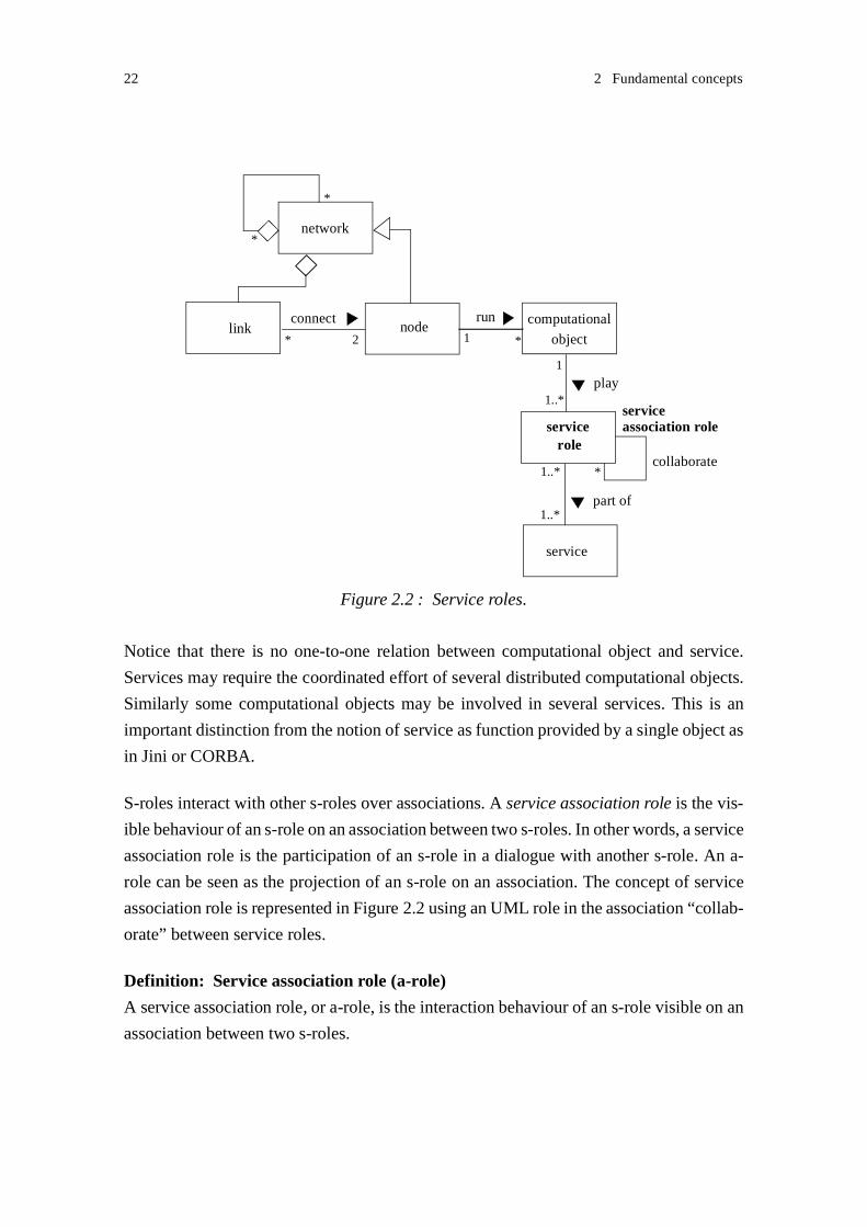
22 2 Fundamental concepts
Notice that there is no one-to-one relation between computational object and service.
Services may require the coordinated effort of several distributed computational objects.
Similarly some computational objects may be involved in several services. This is an
important distinction from the notion of service as function provided by a single object as
in Jini or CORBA.
S-roles interact with other s-roles over associations. A service association role is the vis-
ible behaviour of an s-role on an association between two s-roles. In other words, a service
association role is the participation of an s-role in a dialogue with another s-role. An a-
role can be seen as the projection of an s-role on an association. The concept of service
association role is represented in Figure 2.2 using an UML role in the association “collab-
orate” between service roles.
Definition: Service association role (a-role)
A service association role, or a-role, is the interaction behaviour of an s-role visible on an
association between two s-roles.
Figure 2.2 : Service roles.
connect
*
service
part of
servicerole
1..*
1..*
network
link nodecomputational
object
*
*
* 2
run
*1
play1
1..*
collaborate
serviceassociation role

2.3 Computational viewpoint 23
2.3.1 Service roles
Roles may be introduced in a rather intuitive way. The concept of role is used extensively
every day, either to describe relations between persons, for example family roles such as
mother and daughter, or to describe functions and responsibilities, for example organisa-
tional roles such as professor, secretary, librarian and student. Also in telephony, it is
customary to refer to the A-subscriber and B-subscriber, or the caller and the callee in a
telephony call.
The concept of role was already introduced in the end of the 70’s in the context of data
modelling [Bachman and Daya 1977] and has emerged again in the object-oriented liter-
ature. Roles are used both for data modelling [Wieringa and de Jonge 1991] and
functional modelling [Reenskaug and al. 1992; Kristensen and Østerbye1996; Mezini and
Lieberherr 1998]. In our approach, service roles (s-roles) are functional roles that encap-
sulate the functional properties of computational objects involved in a service.
2.3.1.1 A simple example using service roles
Service roles (s-roles) are introduced by a simple example in Figure 2.3. This figure
shows a collaboration structure diagram for an invitation to participate in some service.
We introduce a new notation for representing collaboration structures1. The invitation
involves two users that interact with two different s-roles: “inviter” and “invitee”. This
figure does not represent the actors playing the s-roles; actors may be represented as
shown in Figure 2.4.
Role and collaboration modelling will be further discussed in Chapter 3. Dialogues
between s-roles will be described in collaboration sequence diagrams, and s-role behav-
iours in a state machine diagrams. Collaboration sequence diagrams get rapidly complex
1. The reason for not using UML collaborations is the distinction we make between actors and roles. This isdesirable in order to have flexibility in allocating roles to actors.
Figure 2.3 : Collaboration structure diagram for service invitation.
user A user B
collaboration invitation - two participants
inviteeinviterservice role
legend:
associationbetween s-roles
(s-role)

24 2 Fundamental concepts
when there exist multiple alternative dialogue cases. Decomposition and composition are
means to reduce the size of collaborations and s-roles.
2.3.2 Collaborations
In the early phases of service and system modelling, scenarios such as use cases [Jacobsen
and al. 1992], use case maps [Miga and al. 2001] and message sequence charts [ITU-T
1999b; Bræk and al. 1999] are often used. These scenarios describe collaborations
between roles. They provide good support for capturing system needs and describing the
main behavioural cases. Scenarios are however not used to model the complete system
behaviour. The main reason is that there exist far too many cases, and among them many
closely related cases. Instead of modelling the complete set of scenarios for a system, one
may explore another approach based on the modelling of basic scenarios and their com-
position [Riehle 1997]. Basic scenarios describe simple or elementary slices of behaviour,
and scenario composition provides a method for merging the basic scenarios into more
complex behaviours.
In our approach, we do not focus on collaborations. Instead we describe roles and their
composition.
2.3.3 Composite service roles
Service roles may be decomposed into smaller behavioural elements that interact or col-
laborate with other s-role elements. For example, the s-role “caller” in a telephony service
may be decomposed into distinct functional elements: inviter, setup-initiator and release-
initiator that are involved during the different service phases: invitation, setup and release.
These functional elements are also considered as s-roles. We will use the term elementary
s-roles to denote s-roles that are not further decomposed. A service feature may be seen
as the result of a collaboration between elementary service s-roles.
Conversely we may produce more complex s-roles (and thus services) by composing s-
roles possibly by reusing existing s-roles. In Figure 2.4 we combine the s-roles “inviter”
and “invitee” in different collaboration schemes in order to produce an invitation with
several participants. We propose two alternatives. In one case, “user A” is supported by
an actor playing the s-role “inviter” twice, and able to invite two other users. In the other
case, “user B” is supported by an actor that can both play the s-roles “invitee” and
“inviter”. Thus “user B” may invite a new participant (“user C”) after being invited in a
service (by “user A”).

2.3 Computational viewpoint 25
Composite s-roles, obtained by composing other s-roles, may be coordinated in various
manners. This will be further discussed in Chapter 4.
2.3.4 Service association roles
A service association role (a-role) is the visible interaction behaviour of an s-role on an
association. Each association involves exactly two s-roles. An s-role that interacts with
several other s-roles provides distinct a-roles on each association. A-roles describe the s-
role behaviour visible on an interface. A-roles abstract the internal behaviour of the s-
roles, and the interactions towards other s-roles. This abstraction facilitates the validation
analysis (see Chapter 5).
In the current distributed processing approaches such as CORBA and DCOM, computa-
tional objects are described by static interfaces limited to the declaration of operation
signatures [OMG 2001; Microsoft Corporation 1996]. Such interface descriptions may
facilitate the construction of a system by providing a means for retrieving objects that may
potentially offer a function or feature, but they do not provide sufficient support for build-
ing a system that behaves correctly. Architectures based on traditional object interfaces
lack two main properties [Luckham and al. 1995]. They only describe the functions pro-
vided by an object, and fail to describe the functions required by an object. This makes it
difficult to determine the effects that changes to an interface may have on other objects.
Moreover, they do not describe the semantics of a connection between objects and the
constraints on using the interfaces. For example, it is not possible to ensure that the inter-
actions between objects will occur in a correct order. This is important when the
invocation of an operation influences the behaviour of future operations, as encountered
in stateful behaviours. This property is not either described by static interfaces.
Figure 2.4 : Service role collaborations for invitation with three participants.
user A
user B
collaboration invitation - several participants
inviter
inviter invitee
invitee
user C
user A user B
collaboration invitation - several participants
invitee
invitee
user C
inviter
computationallegend: associationbetween s-roles
service roleobject (actor) (s-role)

26 2 Fundamental concepts
Service association roles overcome the limitations of static object interfaces. Contrarily
to traditional object interfaces, a-roles describe dialogues or protocols between s-roles.
The association roles on each end of an association complement each other. Thus the a-
roles required by an s-role can be determined from the a-roles provided by this s-role. The
dialogue on an association may be influenced by the events that have previously occurred
in the s-role, i.e. the state of the s-role. This will be discussed in Chapter 6.
A-roles are represented in collaboration structure diagrams as shown in Figure 2.5. A-
roles are described using state diagrams, and sometimes illustrated by collaboration
sequence diagrams. We use the state machine graph representation for reasoning about
correctness. See Chapter 7.
Notice that distinct service roles may provide identical association roles:
• An s-role may implement internal actions that are not visible at the s-role interfaces
(i.e. the a-roles). For example, the role “invitee-with-log” may, in addition to answer-
ing to an invitation, perform logging of the operations being executed, and still provide
exactly the same a-roles as the role “invitee”.
• An s-role may also be extended by adding associations to other s-roles and still main-
tain the same a-roles on existing associations. This is illustrated in Figure 2.6. The new
s-role “invitee-with-redirect” that redirects all incoming invitations to a third party,
extends the s-role “invitee”. The new s-role still provides the same a-role “invitee-
inviter” to the role “inviter”.
An s-role may collaborate with several other s-roles. The behaviour on one association
may influence the behaviour on other associations, and, in the worst case, conflict. S-roles
and a-roles should be specified such that concurrency does not cause deadlocks or other
incorrect behaviours. This will be discussed in Chapter 7.
Figure 2.5 : Service association roles.
user A user B
collaboration invitation - two participants
inviteeinviter
service role
legend:
associationbetween s-roles
service associationrole (a-role)
inviter-invitee
invitee-inviter
inviter-user invitee-user(s-role)

2.4 Engineering viewpoint 27
By maintaining the existing a-role “invitee-inviter” in the example of Figure 2.6, we guar-
antee that the s-roles interact consistently, and that the extended system behaves correctly
with respect to the interface behaviours. Hiding the extension of an s-role may, however,
lead to systems that do not behave according to the users goals. In the example of
Figure 2.6, “user A” intended to invite “user B”; “user A” may not be satisfied with being
redirected to “user C”. We may distinguish between two levels of collaboration
correctness:
• The system level: consistency among a-roles ensures consistent interactions between
s-roles, and a correct behaviour from a system viewpoint.
• The user level: additional constraints are imposed on the actors by requiring actors to
play specific s-roles. This ensures a correct or expected behaviour from a user
viewpoint. This is not further elaborated in this thesis.
2.4 Engineering viewpoint
This thesis does not elaborate the engineering viewpoint.
We assume that actors are implemented on an object-oriented platform that supports dis-
tributed processing. This platform or distributed processing environment (DPE) controls
the execution and management of applications. The DPE supports transparent communi-
cation between the network nodes, and hides the heterogeneity of the underlying systems
(e.g. programming languages, operating systems, network protocols). CORBA is such a
DPE [OMG 2001].
As in the TINA framework [TINA 1995], we assume that the network nodes are able to
interact by means of a communication infrastructure called the kernel transport network.
Figure 2.6 : Extended role - unchanged association role.
user A
collaboration invitation with redirect
inviteeinviter
inviter-invitee
invitee-inviter
inviter-user inviter-invitee
user C
invitee
invitee-user
withredirect
invitee-inviter

28 2 Fundamental concepts
2.5 Summary
In this thesis, the term service is used at the enterprise viewpoint to designate capabilities
provided to systems and users. The focus of the thesis is on communication control serv-
ices that coordinate the participation of multiple users in a service. When modelling
services at the computational viewpoint, we use the term service role (or s-role) to desig-
nate the behaviour of a computational object (or actor) in a service. S-roles collaborate in
order to provide services. S-roles interact over associations; a service association role (or
a-role) is the visible participation of an s-role in an association.

- 29 -
3
Collaboration and service role modelling
The chapter discusses the modelling of collaborations and service roles (s-roles). The role
view and the collaboration view are complementary views that contribute to the descrip-
tion of the system behaviour. While the role view provides descriptions of the behaviour
of individual computational objects or actors, the collaboration view focuses on interac-
tions between actors and facilitates understanding the overall system behaviour. We
propose to use the MSC language to describe collaboration sequences, and the SDL lan-
guage to specify service role behaviours.
A set of basic s-roles is introduced in order to discuss the application of the languages to
s-role and collaboration modelling. These examples will be used later when discussing
service role composition in Chapter 4.
3.1 SDL and MSC as modelling languages
When modelling systems and services, we describe their structures (in terms of compo-
nents), interactions between the system components, and the detailed behaviour of the
components. Two main families of languages are available today for modelling [Bræk
2000]: on one hand the ITU-T languages including SDL [ITU-T 1999a], MSC [ITU-T
1999b], on the other hand UML [OMG 1999] that defines a set of notations such as Class
Diagrams, State Machines, Sequence Diagrams, and Collaboration Diagrams. We have
selected SDL and MSC, mainly because SDL and MSC are formally defined. UML still
lacks a complete semantics.
SDL has a formal semantics that enables an unambiguous interpretation of the system
specification. Using SDL for s-role modelling, we are able to reason completely about s-
role behaviours, interactions between s-roles and composition of s-roles at the design
level. SDL was defined to model distributed systems that combine sequential and concur-
rent behaviours, and provides a set of concepts that fits our needs when composing

30 3 Collaboration and service role modelling
distributed s-roles. The graphical notation augments human comprehension of the mod-
els. Of course, our long experience in using SDL [Haugen and al. 1993; Bræk and al.
1999] has also influenced our choice. Our earlier work makes us confident that complete
and efficient code can be automatically generated from SDL [Floch 1995]. A new version
of SDL, SDL-2000, was recently released [ITU-T 1999a]. SDL is widely used in the
industry and a number of successful experiences have been reported [Færgemund and
Reed 1991; Færgemund and Sarma 1993; Bræk and Sarma 1995; Cavalli and Sarma 1997;
Dssouli and al. 1999; Reed and Reed 2001]. The composite state concept introduced in
SDL-2000 allows one to structure state machines in the same way as Harel’s statecharts
[Harel 1987]. The benefit of composite states will be highlighted in Chapter 4. A draw-
back when using SDL-2000 is that no CASE tools that support the new version are
available yet; all diagrams presented in this thesis were edited with drawing tools.
MSC is a formal language that can be used for the definition of interaction sequences. We
will use MSC to describe simple basic collaborations. The focus of this thesis being s-role
composition and validation, we will not make an extended use of MSC.
3.2 Collaborations
Collaborations describe the interactions between computational objects or actors; they
focus on behaviours across a system rather than the behaviours of individual objects. As
system behaviours will be described in terms of s-roles in this thesis, collaborations will
primarily be used to describe interactions between s-roles rather than interactions between
objects.
We describe collaborations using two diagram types:
• Collaboration structure diagrams describe structures in terms of s-roles involved in a
collaboration and interaction associations between these s-roles. A-roles and the actors
playing the s-roles may also be represented in collaboration structure diagrams. We
propose a new graphical notation for representing collaboration structures. This nota-
tion is introduced in Figure 3.1, where a collaboration structure for invitation is
described. All the concepts that may be of interest in a collaboration structure are
present in this figure. The invitation behaviour enables a user to invite another user to
participate in some service activity.

3.2 Collaborations 31
• Collaboration sequence diagrams describe the interactions between s-roles and
between a-roles. We use the MSC language to describe collaborations sequences. The
collaboration sequence diagram shown in Figure 3.2 describes the interactions
between the s-roles in the collaboration “invitation”. In addition to the system s-roles,
the user roles are also represented in this diagram. The MSC alternative construct is
used to represent possible alternative behaviours. More complex collaborations can be
described by a set of message sequence charts (MSCs) and High Level MSCs
(HMSCs) showing how the MSCs are combined. Data in messages may also be
specified.
Actor B
Figure 3.1 : Invitation: collaboration structure diagram.
user A user B
collaboration invitation
inviteeinviter
service associationrole (a-role)
inviter-invitee
invitee-inviter
inviter-user invitee-user
computationallegend: associationbetween s-roles
service roleobject (actor)
Actor A
(s-role)
Figure 3.2 : Collaboration sequence diagram for service invitation.
user A
request-inviteinvite
notify
alt acceptinvite-accept
request-accept
rejectinvite-reject
request-reject
msc invitation
user Binviter invitee

32 3 Collaboration and service role modelling
In a similar way as in the invitation example, Figure 3.3 presents the collaboration struc-
ture and sequence diagrams for participation release. This behaviour enables a participant
in a service to force another participant to quit the service.
3.3 Service roles
Service roles describe the behaviour played by individual actors. This chapter restricts to
elementary s-roles, i.e non-composite s-roles. Elementary s-roles usually describe simple
behavioural elements and are composed in order to provide more complex behaviours. S-
role composition is discussed in Chapter 4.
The behaviour of s-roles is described using state machines. Describing the behaviours of
individual objects in terms of states and transitions has proven to be of great value, and is
widely adopted in most engineering approaches [Bræk 2000]. We use the SDL language
to specify the s-role and the actors playing these s-roles. As SDL does not define the con-
cept of role, an SDL feature that fits the concept of s-role has to be selected.
SDL systems consist of a structure of communicating agents; SDL agents are meant to
represent computational objects. Agent behaviours are described using state machines.
SDL composite states support the structuring of state machines; they contain nested sub-
states and transitions. As they represent parts of behaviour, we find them well suited to
represent elementary s-roles. We use state types so that s-roles may be instantiated in mul-
tiple combinations with other s-roles to form a complete behaviour.
Figure 3.3 : Participation release: collaboration structure and sequence diagrams.
user A
Actor BActor Arel-init
rel-wait
collaboration release
user B
request-releaseterminate
notify
terminate-ind
user A user Brel-init rel-waitmsc release

3.3 Service roles 33
Modelling convention: In the rest of this thesis, roles will be defined as state types, and
references to roles will be represented by state instances. A state reference that does not
use state instantiation, indicates that the state is a basic state (i.e a non-composite state).
In Figure 3.4, the s-role “inviter” earlier introduced in the collaboration “invitation”, is
specified using an SDL composite state. The definition of labelled entry and exit points
will be justified later. Signal parameters and variables are not represented in this state
machine diagram. Variables may be declared as part of the s-role definition or as part of
the actor playing the s-role. When elementary s-roles are composed within an actor,
shared variables should be declared at the actor level.
In a similar way, Figure 3.5 defines the behaviour of the s-role “invitee” in the collabora-
tion invitation, and Figure 3.6 the s-roles “rel-init” and “rel-wait” in the collaboration
“release”.
3.3.1 Assumptions
An SDL state represents a condition in which the state machine may either consume a sig-
nal instance, or interpret a continuous signal or a spontaneous transition:
• States are usually applied to represent conditions for signal consumption. If a signal
instance is consumed, the associated transition is interpreted.
Figure 3.4 : Inviter: s-role behaviour.
idle
invite-
invite
wait-answer
request-accept
invite-reject
request-accept
request-reject
wait-answer
state type inviter
success failfail
success
request-inviteinvite
request-invite

34 3 Collaboration and service role modelling
• A continuous signal interprets a boolean expression; it is associated to a transition that
can be executed when the boolean expression is true. Continuous signals enable the
designer to model that a certain condition is fulfilled.
• A spontaneous transition specifies a state transition without any signal reception.
Spontaneous transitions enable the designer to model non-deterministic behaviours.
Spontaneous transitions are not needed when modelling s-roles. An s-role represents a
complete behaviour i.e. any action, decision and interaction controlling the s-role behav-
Figure 3.5 : Invitee: s-role behaviour.
idle
notify
wait-answer
inviteaccept reject
invite-accept
invite-reject
wait-answer
state type invitee
success fail fail
success
invite invite
Figure 3.6 : Rel-init and rel-wait: s-role behaviours.
idle
terminate
request-
wait-ind
state type rel-init
terminate-
wait-ind
ind
idle
notify
terminate
state type rel-wait
terminate-ind
request-terminate
releasereleaserequest-release
termi-nate

3.4 Actors 35
iour is described. We will see that spontaneous transitions are of interest when modelling
a-roles that hide parts of the s-role behaviour. This will be discussed in Chapter 6.
We assume that the communication between elementary s-roles can be completely
described using signals. The use of continuous signals is restricted to the composition of
s-roles (see Section 4.1.1 and Section 4.1.2).
Using enabling conditions, it is possible to impose a condition on the consumption of a
signal. The signal is consumed if the condition is true; otherwise the signal remains in the
input port. Enabling conditions are interpreted when entering the state, and while waiting
in the state. We assume that enabling conditions are not used to describe any information
exchange between elementary s-roles. The use of enabling conditions is restricted to the
composition of s-roles (see Section 4.1.1 and Section 4.1.2).
Both assumptions reduce the complexity of the validation analysis. From our long expe-
rience of using SDL, we know that these assumptions are acceptable.
3.4 Actors
Service roles are played by actors. We represent actors using SDL process agents. The
assignment of s-roles to agents is specified by instantiating composite states within these
agents, and, in the case of concurrent composition, other process agents. Concurrent com-
position will be discussed in Section 4.2.
In Figure 3.7, the process agent “inviter” represents an actor playing the s-role “inviter”.
Note that process agent types may also be used.
3.4.1 Service role management as a service role
Actors may play several s-roles. An s-role to be played may be assigned following an
external request, i.e. a request issued by another actor, or it may be selected depending on
the behaviour that previously occurred within the actor. We call service role management,
Figure 3.7 : Actor playing the s-role inviter.
i: inviter
process inviter
/* declarations */

36 3 Collaboration and service role modelling
or s-role management, the behaviour that describes the assignment of s-roles to actors, and
the selection of a specific s-role among several alternative s-roles. S-role management
should be coordinated between actors: actors should play s-roles that interact consistently
with each other. S-role management may also encompass negotiation between actors.
Negotiation enables actors to agree on the s-roles to be played.
S-role management does not directly contribute to services, but rather supports actors in
providing services. However, as s-role management requires collaboration and coordina-
tion between actors, and is also a part an actor plays in a service, we consider the
behaviour related to s-role management as service roles.
The separation between s-role management and the behaviour of the s-role(s) being man-
aged is beneficial. It augments the understanding of the system behaviour, and contributes
to reducing the complexity of extending the system. Alternative behaviours may be intro-
duced by extending the s-role management without making changes to the existing s-
roles. Conversely, the s-roles being assigned may be modified without changing s-role
management.
Sections 3.4.1.1 and 3.4.1.2 describe two main elements of s-role management. Service
role triggering and service role assignment indication are both related to the selection and
assignment of an s-role.
3.4.1.1 Service role triggering
The assignment of an s-role to be played may be decided internally in an actor, or trig-
gered by a request from another actor. In the latter case, a request may either be expressed
explicitly or implicitly. We propose three main behaviour patterns for s-role triggering:
spontaneous s-role triggering, implicit s-role triggering and explicit s-role triggering.
3.4.1.1.1 Spontaneous s-role triggering
We say that an s-role is triggered spontaneously when it is instantiated as part of the log-
ical action sequence of an actor, i.e. when the actor reaches a specific state. The s-role is
triggered as part of the s-role management played by the actor. S-roles that take the initi-
ative to start a collaboration, and thus are not triggered by any external request, are
triggered spontaneously.
Figure 3.8 illustrates spontaneous s-role triggering. The s-role “inviter” that always takes
place after starting the actor, is triggered spontaneously. The s-role “main”, that represents

3.4 Actors 37
some main service activity, e.g. coordinating the allocation of stream channels, is also
triggered spontaneously after a successful invitation. Notice the relevance of the state exit
points “success” and “fail” defined in the s-role “inviter” (see Figure 3.4 on page 33) in
this example.
3.4.1.1.2 Implicit s-role triggering
An s-role is triggered implicitly when its invocation is requested by another actor, and
expressed by a stimulus defined as part of the collaboration to be started and of the s-role
to be assigned.
Implicit s-role triggering is illustrated in the collaboration sequence shown in Figure 3.2
on page 31. For example, the reception of the message “request-invite” triggers the actor
to play the s-role “inviter”. The message is defined as part of the definition of the collab-
oration between the s-roles “user A” and “inviter”. In that case, the actors playing the
requested s-roles are not represented in the collaboration sequence.
The actor playing the s-role “inviter” is specified in Figure 3.9. The actor may also play
other s-roles. The s-role management played by the actor handles the reception of the trig-
gering stimuli, and selects the s-role to be played. In this example, notice the relevance of
the state entry points that were defined in the s-roles “inviter” and “invitee”. An entry
point allows one to enter the desired part of a state.
3.4.1.1.3 Explicit s-role triggering
An s-role is explicitly triggered when its triggering is requested by another actor, and
expressed by a stimulus defined explicitly for triggering purposes. This stimulus specifies
the s-role to be played.
Figure 3.8 : Spontaneous s-role triggering.
i:inviter
process inviter
success fail
m:main

38 3 Collaboration and service role modelling
Explicit triggering is illustrated in Figure 3.10. The message “play” represents the explicit
request and contains information about the s-role to be played. The actor that is requested
to play the s-role is specified in the collaboration sequence. The complete collaboration
for invitation is not described here; instead an MSC reference is made to the remaining
sequence in the collaboration. The s-role management played by the actor handles the
reception of the explicit request message “play”, and selects the s-role to be played. Sim-
ilarly to the previous case, the s-role “inviter” is entered through a state entry point. The
process agent “actor-inviter” may be extended allowing the selection of other s-roles.
Explicit s-role triggering is required in a Plug-and-Play approach when there is a need for
negotiating or learning the s-roles to be played [Floch and Bræk 2000].
Figure 3.9 : Invitation: implicit s-role triggering.
ir:inviter
idle
request- invite
ie:inviteevia request- via invite
invite
invite
initiateinvitation
reply toinvitation
process inviter-invitee
play (inviter)
request-invite
user A actor-inviter
inviter
invitation-continue
process actor-inviter
i:inviter
roleinviter else
play
idle
(role)
Figure 3.10 : Invitation: explicit s-role triggering.
msc invitation request
via request-invite

3.4 Actors 39
3.4.1.2 Service role assignment indication
The assignment of s-roles needs to be coordinated between actors. S-role assignment indi-
cation is used to report the assignment of an s-role. It usually takes place after a request
for triggering a new s-role. Similarly to triggering, several behaviour patterns for assign-
ment indication may be defined. We propose two main patterns: implicit s-role
assignment indication and explicit s-role assignment indication.
In implicit s-role assignment indication, indication about the s-role assignment is implic-
itly expressed by a stimulus defined as part of the collaboration being started and of the
s-role being assigned. Implicit assignment indication may be applied after explicit or
implicit s-role triggering. An example of implicit indication was given in Figure 3.2 on
page 31. The messages “request-accept” and “request-reject” are stimuli that indicate that
the s-role “inviter” is being played.
In explicit role assignment indication, the actor, or role management played by the actor,
indicates, by a stimulus defined explicitly for indication purposes, whether or not the
requested s-role has been instantiated. Explicit assignment indication may be applied after
explicit or implicit triggering. Explicit assignment indication may indicate that an alter-
native s-role to the requested s-role is preferred. Explicit assignment indication is
illustrated in Figure 3.11.
play (inviter)
request-invite
user A actor
inviter
invitation-continue
process actor
roleinviter else
play
idle
(role)
Figure 3.11 : Invitation: explicit s-role assignment indication.
msc invitation request
play-grant
play-grant play-reject
alt
play-reject
i:invitervia request-
invite

40 3 Collaboration and service role modelling
Similarly to triggering, explicit s-role assignment indication requires the actors to be rep-
resented in the collaboration sequences. The explicit approach also introduces
supplementary signalling leading to increased traffic and processing loads. Again, the
explicit approach is attractive as a part of role negotiation.
3.4.2 Extension to the MSC language
The MSC language does not provide any notation for expressing structural relations
between instances in a sequence chart. It is not possible to indicate that an s-role instance
is executing as part of an actor behaviour, or that two s-roles execute within the same
actor. Using instance decomposition is not a satisfying solution. One weakness of decom-
position is that two charts need to be defined: one showing the collaboration between the
composite instance and the other instances, one showing the collaboration within the com-
posite instance. Another weakness is that the complete sequence of messages between the
composite instance and the other instances needs to be specified on the chart where the
composite is referred to.
We introduce an extension to MSC allowing us to group instances in a chart, more specif-
ically actors and s-roles in our work. A dashed frame symbol containing several MSC
instances indicates that the instances execute within the same actor. Figure 3.12 illustrates
this extension to MSC. We do not differentiate between actor and s-role in the collabora-
tion sequence diagram. The actor behaviour describes the s-role management, that is itself
an s-role.
Figure 3.12 : Grouping actors and s-roles: extension to MSC.
play (inviter)
request-invite
user A actor-inviter
inviter
invitation-continue
msc invitation request
play-grantalt
play-reject

3.5 Associations 41
3.5 Associations
As our work focuses on s-role composition and validation, we omit describing the mod-
elling of system structures. S-roles interact over associations that can be described in SDL
in terms of channels. We assume that the signals exchanged between two elementary s-
roles are conveyed on the same communication path, where a communication path is con-
stituted by a sequence of connected channels. With this assumption, we ensure that signal
ordering is preserved during transport, i.e. signals are received in the same order as they
are sent.
3.6 Summary
The SDL language is used to model s-roles and actors. S-roles are specified using SDL
composite states, and actors using SDL process agents. We distinguish between the
behaviour required to manage s-roles from the behaviour of the s-roles to be assigned.
The MSC language is used to model collaborations. An extension to the MSC language
is proposed that supports the grouping of actors and the s-roles they play.

42 3 Collaboration and service role modelling

- 43 -
4
Service role composition
This chapter discusses the composition of service roles (s-roles) within an actor. The coor-
dination of the composition of s-roles across actors is presented in Chapter 8. Through the
composition of s-roles we aim to produce the complete behaviour of an actor in a service.
Composition may be applied incrementally. Composite s-roles obtained from the compo-
sition of elementary s-roles may themselves be composed with other s-roles.
There exist various types of dependencies between s-roles that constrain the form of com-
position that can be applied on s-roles. This chapter presents different forms of
composition, and discusses their properties. While sequential composition enforces
behaviour ordering, concurrent composition supports simultaneous behaviours. Sequen-
tial composition encompasses true sequential composition, guarded sequential
composition, choice and disabling. S-roles that are composed concurrently may execute
more or less independently.
Ideally s-roles should be specified without making assumptions about how they are going
to be composed with other s-roles. We define simple general design rules that enable s-
roles to be easily composed. Using these rules, no supplementary behaviour needs to be
specified within the s-roles being composed sequentially. On the other hand, s-roles that
are composed concurrently may require explicit coordination behaviour. We propose
design patterns for the coordination of concurrent s-roles.
SDL-2000 is used to model the different composition classes [ITU-T 1999a]. We select a
set of SDL concepts for the realisation of s-role composition, and draw out general guide-
lines for the specification of the s-role to be composed. The basic s-roles introduced in
Chapter 3 are used to illustrate composition.

44 4 Service role composition
4.1 Sequential composition
Two s-roles are sequentially composed if the execution of one of them precedes the exe-
cution of the other. The s-role executing first must be completed before the other can start
its execution. Using LOTOS terminology, we may also say that the execution of the first
s-role enables the execution of the second s-role [ISO 1989]. The sequential composition
of s-roles leads to a new s-role, a composite s-role that may itself be composed with other
s-roles.
We represent true sequential composition in SDL by linking the elementary s-role states
in a composite state. The ordering of execution of the composed s-roles is enforced by the
definition of the composite state. No adaptation needs to be done in the s-roles to be com-
posed in order to deal with the composition.
The s-role obtained by composing sequentially “inviter” and “rel-init” (see Figure 3.4 on
page 33 and Figure 3.6 on page 34) is shown in Figure 4.1. Here we enforce the s-role
“rel-init” to take place after “inviter” even if the invitation has been rejected. We postpone
using the exit points of “inviter” to Section 4.1.2.1, this to illustrate true sequential com-
position. SDL constrains us to attach the “*” symbol to the connection between “inviter”
and “rel-init”. In our example, “*” means that the connection is chosen for any non-
referred exit point of “inviter” (i.e. “fail” and “success”).
Guarded sequential composition, choice and disabling are extended forms of sequential
composition. They all ensure mutual exclusion between the s-roles being composed and
impose an order of execution. They are also described in SDL by linking the elementary
s-role states in a composite state. Guards and disabling triggers are added that control the
execution of s-roles. Sections 4.1.1, 4.1.2 and 4.1.3 describe these forms of composition.
Figure 4.1 : Sequential composition of inviter and rel-init.
i:inviter
r:rel-init
state type sequence
*

4.1 Sequential composition 45
4.1.1 Guarded sequential composition
Guarded sequential composition extends the basic sequential composition. Guards are
used that prefix s-roles. Guards describe preconditions that must be satisfied prior to the
execution of s-roles. The ordering of sequential composition is maintained.
Guards may either be expressed as predicates over local conditions (i.e. conditions set
within the actor executing the s-role), or external conditions (i.e. conditions set by other
actors). Guards based on internal conditions are typically used when the composite s-role
executes concurrently with other s-roles within the same actor (see Section 4.2). External
conditions facilitate the coordination of composition across actors. They are further dis-
cussed in Chapter 8.
In SDL, we describe guards as continuous signals or enabling conditions. In the case
where s-roles are triggered spontaneously (see Section 3.4.1.1), only continuous signals
are used. A continuous signal interprets a boolean expression; it is associated to a transi-
tion that can be executed when the boolean expression is true. Continuous signals are
interpreted upon entering the state to which they are attached when no signal can be con-
sumed, and while waiting in the state. An enabling condition associates an additional
condition on the consumption of a signal. The signal is consumed if the condition is true;
otherwise the signal remains in the input port. Enabling conditions are interpreted when
entering the state, and while waiting in the state.
Figure 4.2 illustrates guarded sequential composition in SDL. Sequence (a) uses a contin-
uous signal as a guard. Sequence (b) uses an enabling condition. The condition “ready”
may represent an internal condition such as the state of a stream channel, or an external
condition such as the state of an interacting actor. The s-role “main” represents any main
activity performed in the service. In sequence (a), the basic state1 “idle” is introduced so
that the continuous signal does not force the exit of the s-role “inviter”. The execution of
s-role “inviter” should be completed before the continuous signal is interpreted.
4.1.2 Choice among alternative behaviours
Choice among alternative behaviours extends the basic sequential composition. Using
choice, alternative s-roles can be specified in a sequential composite s-role. The selection
of a behaviour among the alternative behaviours in a choice may be controlled by guards
1. Recall the modelling convention introduced in Chapter 3. A direct reference to a state indicates that thestate is a basic state (i.e. a non-composite state)

46 4 Service role composition
or external triggers. Guards are expressed as predicates over conditions that are either
resolved locally, i.e. within the actor executing the s-role, or globally, i.e. their resolution
requires some interaction with other actors. External triggers are elements of some inter-
action with other actors. They belong to the definition of an s-role, either the s-role to be
selected and assigned (implicit triggering) or the management s-role (explicit triggering).
Explicit and implicit triggering have been defined in Section 3.4.1.1.
4.1.2.1 Choice based on a condition
In SDL, guards are either specified using a named return (from a state), a set of continuous
signals, or a combination of these mechanisms. A named return describes a state exit con-
dition. State exit conditions are defined by labelled exit points. The set of continuous
signals representing guards should describe a complementary set of conditions. While a
named return reflects a condition set by the s-role immediately preceding the occurrence
of a choice, continuous signals may be related to actions that have taken place at any time
before the occurrence of a choice, or that are taking place within another s-role executing
concurrently. The resolution of a condition specified using a continuous signal may
require an interaction with other actors. This increases the complexity of the validation
analysis and should be restricted to the synchronisation of s-role composition across
actors (see Chapter 8).
Figure 4.2 : Guarded sequential composition.
state type guarded-sequence-1
i:inviter
ready continuous signalevent:
r:rel-init
m:main
state type guarded-sequence-2
idle
ready enabling conditionevent:
r:rel-init
m:main
request-invite
i:invitervia request-
invite
*
idle
(b) guarded implicit triggering
(a) guarded spontaneous triggering

4.1 Sequential composition 47
Figure 4.3 illustrates a sequential composition tree where the exit conditions from the s-
role “inviter” control the selection of the further behaviour. Notice that although the con-
dition is resolved locally, it may represent a global collaboration condition.
This example is extended in Figure 4.4. Here the selection of a main activity is based on
a set of continuous signals representing the content of the user profile.
Modelling a choice based on a condition is straightforward. No supplementary signalling
is needed to control the choice. The s-roles specified as alternative behaviours do not need
any adaptation. Labelled exit points facilitate the specification of choices. As illustrated
in Figure 4.1, labelled exit points may be defined that are not used in the composite state.
Figure 4.3 : Choice among alternative behaviours using exit conditions.
i:inviter
r:rel-init
state type sequential-tree
success fail
m:main
Figure 4.4 : Choice among alternative behaviours using continuous signals.
i:inviter
r:rel-init
state type sequential-tree
success fail
x:main-X y:main-Y
idle
profile= X
profile= Y

48 4 Service role composition
Therefore we recommend defining them in any case. We state this recommendation in our
first design rule or D-rule as we call it throughout this thesis.
D-rule: Exit conditions
Labels that express exit conditions should be attached to the exit points of the states mod-
elling s-roles.
4.1.2.2 Choice based on an external trigger
In SDL external triggers are specified using signals. The consumption of these signals is
specified as part of the composite state where the choice is made. In the case of implicit
triggering, triggering signals belong to the s-role to be selected. The triggered s-role is
then entered through a state entry point allowing one to enter the triggered state after the
consumption of the signal. No major specification change of the s-role is required in order
to deal with the composition. Labelled entry points facilitate the specification of choices,
and should be defined in any s-role.
D-rule: Entry conditions
Entry points that represent entry through external triggering should be defined in the states
representing s-roles.
Figure 4.5 illustrates a choice based on an external trigger. Here a service user may either
initiate an invitation or reply to an invitation. The user is represented by a single actor in
the service framework, that either plays the s-role “inviter” or “invitee”. The selection of
an s-role is triggered by the external signals “request-invite” or “invite”.
Any initialisation to be performed when entering the triggered s-roles through the default
start node should also be performed when entering through entry conditions. Entry proce-
dures can be defined that describe initialisation tasks. SDL entry procedures are called
implicitly when entering or re-entering a state1.
D-rule: Entry procedure
An entry procedure should be defined that describes the tasks to be performed when enter-
ing an s-role.
1. Re-entering a state is discussed in Section 4.2.3.5.

4.1 Sequential composition 49
4.1.3 Disabling
An s-role disables another s-role if its execution inhibits the execution of this other s-role.
Unlike suspension (see Section 4.2.3.5), disabling has a permanent interruption effect.
The disabled s-role is forced to complete execution.
We represent disabling in SDL by linking the elementary s-role states in a composite state,
where the disabling s-role state is triggered by the reception of a signal. The reception of
the disabling signal should take priority over the reception of other signals. This is
expressed by means of a priority signal. The disabling signal may either belong to the def-
inition of the disabling s-role (implicit triggering) or the management s-role (explicit
triggering). In the case of implicit triggering, the disabling s-role is entered through a state
entry point. No major specification change of the disabling s-role is required. The same
design rules as for choice based on an external trigger apply (see “entry conditions” and
“entry procedure” in Section 4.1.2.2).
In the case where an exit procedure is defined in the disabled s-role, the exit procedure is
executed upon disabling. This enables the designer to describe termination operations of
the disabled state. However, SDL exit procedures can only contain a single transition, and
therefore do not allow one to describe two-way interactions with other actors. When dis-
abling occurs, the process agent queue may contain signals that have been addressed to
the disabled s-role. The retrieval of these signals from the input port leads to unspecified
Figure 4.5 : Choice among alternative behaviours based on an external signal.
ir:inviter
r:rel-init
state type sequential-tree
success fail
m:main
idle
request- invite
ie:invitee
r:rel-wait
success fail
m:main
via via invite
idle
notify
wait-answer
invite accept reject
invite-accept
invite-reject
wait-answer
state type invitee
success fail
fail
success
invite
initiateinvitation
reply toinvitation
request-invite
invite
invite

50 4 Service role composition
signal reception. As unspecified signal reception is not desirable, disabling should only
be applied in critical situations where interruption is necessary. This is further discussed
in Chapter 8.
D-rule: Exit procedure
When designing an exit procedure, take into account that the state may be exited through
an exit node, or when a transition attached to the composite state is interpreted.
Figure 4.6 illustrates disabling of the s-role “inviter”. In this example, release may be
forced when the invitation or the main service activity have not yet completed, or it may
take place as a normal case after the completion of the main activity.
Figure 4.6 : Disabling composition.
i:inviter
state type service-role-with-disabling
release
terminate
request-
wait-ind
terminate-
wait-ind
ind
idle
request-release
state type rel-init
request-r:rel-init
success fail
m:main
r:rel-init
release
viarequest-release
r:via
request-release
release
release

4.2 Concurrent composition 51
4.2 Concurrent composition
With concurrency, we do not mean true concurrency, but rather interleaving. Two or more
s-roles are composed concurrently if their executions interleave. This means that the
actions in the s-roles never occur simultaneously. As s-roles are composed within a com-
putational object and share processing resources, simultaneousness is neither necessary
nor desirable. S-roles composed concurrently have overlapping lifetimes. They may exe-
cute in an independent manner, or their execution may require explicit coordination.
We distinguish between static concurrent composition, where the s-roles and the number
of s-roles that are being composed are set at design time, and dynamic concurrent compo-
sition, where s-roles are created dynamically upon decisions made at run-time. Static
concurrent composition is, for example, attractive for combining main tasks with back-
ground activities running continuously, such as logging or status checking. Static
concurrent composition can also be applied when a fixed number of instances of an s-role
run independently and concurrently. For example, a service may require one of its partic-
ipants to invite exactly two other participants. Dynamic concurrent composition, on the
other hand, is relevant when a variable number of s-role instances is needed.
We propose to represent concurrent composition using process agents in SDL (see
Section 4.2.1). A process agent representing an actor may contain other process agents
representing s-roles. Inner process agents execute in alternating manner. It is possible to
specify several levels of concurrency, as inner process agents may themselves contain
process agents. In the case of dynamic concurrent composition, the s-role process agents
are created dynamically at run-time.
An alternative to process agents is provided by state aggregation (see Section 4.2.2). SDL
state aggregation is a particular form of composite state. It defines a partitioning of a state.
A state aggregation consists of multiple states, which have an interpretation that is inter-
leaved at the transition level. The state aggregation construct replaces the SDL-92 service
construct [ITU-T 1993a]. State aggregation has many limitations, and can only be used to
model some cases of static independent concurrent composition of instances of distinct s-
roles. In Section 4.2.2.1, we propose simple extensions to SDL that make state aggrega-
tion easier to apply.

52 4 Service role composition
4.2.1 Using process agents
The concurrent execution of multiple s-role instances increases the complexity of a spec-
ification. We propose structural design rules for using process agents in the modelling of
concurrent composition. These rules contribute to an orderly design, and ease the reada-
bility of the descriptions.
We introduce a new role responsible for managing the set of concurrent s-roles. The man-
ager role and the concurrent s-roles are specified within the same process agent. A generic
model is presented in Figure 4.7:
• The managing role “manager” is defined as a composite state. In that way, it can be
itself composed with other service roles.
• The s-roles to be composed “service-role” are defined using composite states. These
composite states are instantiated within s-role process agents “service-role-agent”. In
the case of static concurrent composition, the initial number of instances of the process
agent should be specified.
Two slightly different manager roles are introduced through examples in Section 4.2.1.1
and Section 4.2.1.2. In both sections, the initial service example is extended in order to let
the service user invite several participants. This is achieved by concurrently composing
multiple “inviter” s-roles.
Figure 4.7 : Concurrent composition using process agents.
rc:
state type manager
sc:
process type service-actor
sa:
manager-role
process type service-role-agent
sr:service-role
service-role-agent
manager

4.2 Concurrent composition 53
4.2.1.1 Allocation manager
The purpose of an allocation manager is to assign a resource, here an s-role, to a request.
This is illustrated in the collaboration diagram in Figure 4.8. The new role “allocator” is
introduced that assigns an s-role “inviter” to handle the invitation request. Here the s-role
“inviter” is created dynamically. The collaboration between “inviter” and “user A” is
identical to the initial collaboration invitation (see Figure 3.2 on page 31). In Figure 4.8,
a single invitation sequence is represented. The sequence may be re-iterated.
The behaviour of the role “allocator” and the process agents involved in the service are
described in Figure 4.9.
The introduction of the allocator role slightly changes the initial addressing scheme: the
s-role “inviter” no longer replies to the sender of the request message. We recommend
specifying the reference(s) of the entity(ies) to be addressed by the reply in request mes-
sages. Here the message “request-invite” should contain the address of “user A”. Using
SDL gates, channels and connections, it is also possible to specify a system structure that
enforces the correct addressing of the signals. However, such an approach provides a lim-
ited addressing support. It cannot be applied when the requesting instance is a member of
an instance set. Furthermore, it is not appropriate for dynamic system structures.
D-rule: Addressing information
Request messages should contain the addresses of the s-roles waiting for a reply.
Using this design rule, no supplementary behaviour needs to be specified in the s-roles
being composed.
Figure 4.8 : Role allocator in concurrent composition.
user A
request-
invitenotify
altaccept
invite-acceptrequest-accept
msc invitation
user Binviter invitee
allocator
reject
invite-rejectrequest-reject
invite
request-invite

54 4 Service role composition
4.2.1.2 Mediation manager
The purpose of a mediation manager is to assign a resource, here an s-role, to a request,
and to mediate messages to and from that s-role. This is illustrated in the collaboration
diagram in Figure 4.10. The new role “mediator” is introduced that assigns an s-role
“inviter” to handle the invitation request, and that re-transmits the messages from the s-
role “user A” to the s-role “inviter”, and conversely. The role mediator provides the same
service association role as the s-role “inviter” to the s-role “user A”, and the same service
association s-role as the s-role “user A” to the s-role “inviter”. The mediator is actively
involved during the whole collaboration, thereby introducing some delay in the interac-
tion between the s-s-role “user A” and the s-role “inviter”.
The mediation manager may also support other functions in addition to re-transmission.
For example, it may provide support for grouping multiple requests. Instead of generating
a request for each invited participant, the user may generate a single group request that is
processed and split by the mediator into individual requests. Conversely, the mediator
may concatenate a single answer from the individual answers. A drawback with such
additional functions is that changes to the basic collaboration require modifications to be
made in the mediator.
Figure 4.9 : Concurrent composition of invitation using an allocator.
sc:allocator
process type service-actor
i:inviter
process type inviter
i:inviter
state type inviter-allocator
idle
request-
inviter
morerequests?
-
no yes
[request-request-inviteto offspring
a:
r:release
state type allocator
inviter-allocator
m:maininvite
invite]

4.2 Concurrent composition 55
4.2.2 Using state aggregation
State aggregation provides a simple approach to the modelling of the static concurrent
composition of instances of distinct s-roles. It defines a partitioning of a state into multiple
states. Execution interleaving is enforced by the semantics of state aggregation.
State aggregation is illustrated in Figure 4.11. Two s-roles “main” and “status-check” are
composed concurrently. The s-role “status-check” is a background activity that enables
other actors to request information about the actor state while the main activity is taking
Figure 4.10 : Role mediator in concurrent composition.
user A
invitenotify
altaccept
invite-acceptrequest-accept
msc invitation
user Binviter invitee
mediator
request-accept
rejectinvite-reject
request-reject
request-reject
request-invite
request-invite
Figure 4.11 : Static concurrent composition of the roles main and status.
i:inviter
r:rel-init
state type service-role
success fail
m:main
s:
state aggregation type concurrent
c:concurrent
status-check

56 4 Service role composition
place. The composite s-role obtained by concurrent composition is itself composed
sequentially with the s-roles “inviter” and “rel-init”. According to SDL semantics, the s-
role “concurrent” terminates when both the s-roles “main” and “status-check” have
terminated.
Using state aggregation, sequential and concurrent composition can easily be combined
in a state graph. However, state aggregation is difficult to apply. The SDL definition of
state aggregation introduces several restrictions:
• The input signal sets of the state partitions must be disjoint. Thus state aggregation is
not the appropriate technique to model static independent concurrent composition of
instances of the same s-role.
• The composite state terminates when all state partitions have terminated, or when a
transition is triggered at the composite state level. SDL does not provide any support
for specifying that a state partition (or a group of state partitions) forces the exit of the
composite state. Additional signalling has to be defined for forcing termination as
illustrated in Figure 4.12, where the termination of “main” forces the termination of the
state aggregation. On termination, any exit procedure defined for the state partitions is
executed. The exit procedure of the state aggregation is also executed.
• Although the exit points from the state partitions may be connected to the exit points
of the state aggregation, SDL restricts the appearance of each exit point in exactly one
connection. Thus it is not possible to define exit conditions of the state aggregation
from the exit conditions of the state partitions in a flexible way. Figure 4.13 illustrates
Figure 4.12 : State aggregation: forcing termination.
i:inviter
r:rel-init
state type service-role
success fail
m: main-
status-check
state aggregation type
c:concurrentwith-exit
concurrent
state type main-with-exit
m:main
exit-main
exit-main

4.2 Concurrent composition 57
the connection of exit points. Two exit points are defined for the state aggregation, and
connected to exit points of the state partitions. According to SDL, the exit point “fail”
of “role-1” must appear in exactly one connection, preventing us from specifying any
exit point of the state aggregation for the case where “role-1” exits via “fail”, and “role-
2” via “success”. If so happens, SDL specifies that the exit point of the state aggrega-
tion is chosen in a non-deterministic way.
4.2.2.1 Extensions to the SDL language
We suggest introducing simple extensions to SDL to facilitate using state aggregation for
modelling the static concurrent composition of instances of distinct s-roles. We propose
two sets of extensions:
1. The termination of a state partition (or a group of state partitions) may force the termi-
nation of the state aggregation. This can be modelled as shown in Figure 4.14. The exit
point of the state aggregation is connected to the exit point of the state partition “main”
(here DEFAULT1), but not to any exit point of “status-check”. The connection of an
exit point to a single state partition indicates that the termination of the partition forces
the termination of the state aggregation.
2. Exit points may appear in multiple connections, and exit conditions of the state aggre-
gation can be expressed as logical expressions of the exit conditions of the state
partitions. These extensions are modelled in Figure 4.15. Connection lines are not rep-
1. DEFAULT is defined in SDL; it indicates unlabelled entry and exit points.
Figure 4.13 : State aggregation with exit connection points.
role-1
role-2
state aggregation type concurrent
success
fail
success
success
fail
fail
Figure 4.14 : Extension to state aggregation: termination.
main
status-check
state aggregation type concurrent
doneDEFAULT

58 4 Service role composition
resented graphically here. We prefer a textual representation. Qualifiers are used that
refer to the state partitions.
We have also considered a set of extensions for supporting non-disjoint input signal sets
of the state partitions. Such an extension requires support for the identification and
addressing of sub-states. Furthermore, the creation of states would enable dynamic con-
current composition to be described using state aggregation. In that way, it would be
possible to use a single SDL concept, the composite state, to model sequential and con-
current compositions. However, with these extensions, the state concept becomes
identical to the process agent concept, the main difference being that states can be linked
sequentially. As this set of extensions is complex, we suggest representing concurrent
composition using process agents when state aggregation cannot be used.
4.2.3 Coordination
S-roles that are composed concurrently may execute more or less independently. Their
composition may require explicit coordination behaviour. For example, in the sharing of
a resource, the phases in a service may have to be coordinated. Unlike the management of
concurrent s-roles, coordination often requires behaviour to be added to the s-roles that
are composed. Coordination is often application dependent. In this section, we propose a
set of design patterns for the coordination of s-roles. As we will see, SDL provides rather
poor support for the definition of generic coordination behaviours. First, let us consider
some examples.
4.2.3.1 Examples
4.2.3.1.1 Alternating execution
A service enables a user to invite several other participants at any time during the service
session. For logical reasons, the main activity in the service has to be suspended while a
new invitation takes place.
Figure 4.15 : Extension to state aggregation: exit conditions.
role-1
role-2
state aggregation type concurrent
success := <role-1> success AND<role-2> success
fail := <role-1>fail OR<role-2>fail

4.2 Concurrent composition 59
This can be modelled by the concurrent composition of the s-roles “main” and “inviter”
where their execution alternates. The s-roles have overlapping lifetimes, but the s-role
“main” is suspended during invitation request. Invitation request and termination are two
relevant events for the coordination of the execution of the s-roles. The case is illustrated
in Figure 4.16. When “inviter” starts, it suspends “main”. “main” is resumed when invi-
tation terminates. In this example, the invitation is simplified (i.e. no rejection).
4.2.3.1.2 Coordinating multiple instances
A service enables a user to invite several other participants to the service session. Invita-
tion takes place when the service session is started and requires negotiation of the
transport streams characteristics. Negotiation takes place between an invitation request
phase and a confirmation phase.
This can be modelled by the concurrent composition of multiple instances of the s-role
“inviter”. We assume that the actor that has initialised invitation decides upon the charac-
teristics of the transport streams. The s-roles “inviter” execute concurrently until the
negotiation phase. At that point, the s-roles should coordinate and agree on a common
transport stream configuration. This configuration may be computed by a configuration
coordinator that executes concurrently with the s-roles “inviter”. When a configuration
has been generated, the s-roles “inviter” can further proceed concurrently. The case is
illustrated in Figure 4.17. In order to simplify the message sequence, a single instance of
“inviter” is shown in the diagram. Invitation has been extended to two phases, configura-
tion and confirmation.
Figure 4.16 : Alternating execution between inviter and main.
user A
request-
invitenotify
accept
invite-acceptrequest-accept
msc invitation
user Binviter invitee
main
invite
request-invite
allocator
suspend
resume
continue-activity

60 4 Service role composition
4.2.3.1.3 Resource sharing
A service may enable a user to invite several other participants to a service session. The
elementary invitation s-role is extended with a dialogue with the requesting user. Through
this dialogue the user is authenticated by the remote s-roles “invitee”. The user terminal
supports only one dialogue at a time.
This can be modelled by the concurrent composition of multiple s-role instances “inviter”.
The s-roles execute concurrently during their initial phase. Invitation is suspended if the
terminal resource is not available for authentication dialogue. Invitation is resumed when
the terminal resource can be allocated.
4.2.3.2 Coordination events
Coordination events trigger the coordination of concurrent s-roles. They may be related
to the state of a shared resource or the stage of a service phase. As we have seen, coordi-
nation events are often service dependent. Generic events may however be defined for a
set of services. Generic user states such as “busy”, “not responding” are defined in Parlay
[Parlay 2000f]. The development of reusable s-roles requires generic events to be
identified.
In SDL, coordination events may modelled by input signals, enabling conditions, or con-
tinuous signals.
Figure 4.17 : Synchronisation: computing a common profile.
user A
request-
invite
notify
acceptinvite-accept
request-accept
msc invitation
user Binviter invitee
configure
invite
request-invite
allocator
required-profile
adopted-profile
profiles
set-profile

4.2 Concurrent composition 61
4.2.3.3 Coordination modes
The composed s-roles may execute concurrently between two coordination events, or
alternating:
• In the first case, the s-roles evolve independently until they reach coordination points,
where they wait for some coordination event to occur. This is the case in the example
shown in Figure 4.17. The “inviter” instances execute independently until they wait for
a configuration profile to be computed.
• In the later case, only one of the s-roles can execute at a time; the other s-roles are sus-
pended until a coordination event is reached where, possibly, one of the suspended s-
role resumes while the activate s-role is suspended. Alternating execution can be
employed when two s-roles share a common resource. It ensures mutual exclusion
between s-roles. The coordination events serve as guards for interleaving between s-
roles. In Figure 4.16, the s-role “main” and “inviter” execute alternating. Suspension
is further discussed in Section 4.2.3.5.
4.2.3.4 Coordination interaction
Coordination between concurrent s-roles may be communicated directly between the con-
current s-roles or through a coordinator. This is illustrated in the case of alternating
execution in Figure 4.18. The message “event” represents the notification of a coordina-
tion event. The messages “suspend” and “resume” control the alternating execution.
Confirmation should be added if suspension cannot take place in every s-role state. Case
(b) is better suited when the composition involves more than two s-roles. In the case of
concurrent execution, the messages “suspend” and “resume” are not needed. The notifi-
cation event serves as a coordination.
Figure 4.18 : Alternating execution: coordination patterns.
coordinator
msc coordination
role-1
event
resume
role-2
suspend
role-1
msc coordination
role-2
eventresume
suspend
(a) direct coordination between s-roles (b) coordination using a coordinator

62 4 Service role composition
4.2.3.5 S-role suspension and resumption
The alternating execution of concurrent s-roles requires mechanisms for the suspension
and resumption of s-roles. Suspension and resumption are triggered by the notification of
coordination events. A suspended s-role enters a suspended state where all signals
expected by the s-role, except the resumption trigger should be saved. Certain signals, e.g.
exceptions, may also be enabled in a suspended state. We introduce a simple design pat-
tern for suspension and resumption. SDL provides rather poor support for the definition
of generic behaviours. This is explained in this section.
Suspension may be enabled in a subset of the s-role states or any s-role state. In the first
case, suspension has to be modelled as part of the s-role definition; suspension is applica-
tion-dependent. In the second case, suspension may be modelled as part of the s-role
definition or at the s-role level. We prefer the later approach as it does not require any sup-
plementary behaviour to be specified within the s-role being composed. The two cases are
illustrated in Figure 4.19.
Case (a) is simplified and shows only the suspension of one state. The suspension is con-
firmed as it cannot take place in every s-role state. As it is not possible in SDL to test the
value of a state, the value of the suspended state should either be stored in a variable, or
distinct suspended states should be defined for the distinct active states that can be
suspended.
Figure 4.19 : Suspension and resumption at different levels.
process type service-role
suspended
s:service-
suspend *
suspended
resume
role
(b) suspension of the whole s-role
s:service-role
state type service-role
suspended
active
suspend *
active
suspended
resume
(a) suspension of a particular s-role state
suspend-indwithhistory
(extension to SDL)

4.2 Concurrent composition 63
In case (b), the definition of SDL composite states makes the specification of a simple
design pattern for s-role suspension intricate. On resumption, the s-role should be re-
entered in the state it was left. The SDL history concept supports the re-entering of a com-
posite state. However, the state specified in the nextstate node with history must be the
state in which the transition was activated. Thus, in case (b) in Figure 4.19, using history
is normally not allowed. The intermediate state “suspended” introduced between leaving
and re-entering “active” prevents us from using history.
Another difficulty is introduced by the SDL definition of entry procedure. When re-enter-
ing a composite state with history, the entry procedure of the composite state is invoked.
No mechanism in SDL is provided to distinguish between entering or re-entering a state.
Thus, in the case a state can be re-entered, entry procedures are not appropriate to describe
initialisation tasks that only need to be performed on entering the state for the first time.
Some intricate work-arounds using flags may be introduced. However such work-arounds
introduce dependencies between composite s-roles and sub-roles. This is not desirable.
4.2.3.5.1 Application dependent behaviour
The behaviour of s-roles has often to be taken into account when suspension is introduced.
As already discussed, some particular states may not be suspended. Timers, interactions
with other actors, and real-time requirements may also influence the suspension of an s-
role. Should timers be stopped before suspending an s-role? If not, should expired timers
be taken into account in suspended states? Or should they be restarted? There is not one
single answer to these questions. The application has to be taken into account. We con-
clude that suspension behaviour can only be defined as a pattern that the designer may
refine according to the application needs.
4.2.3.5.2 Suspension vs. disabling
While suspension is defined as a temporary interruption, disabling is permanent (see
Section 4.1.3). Suspension may be modelled in the same manner as disabling using trig-
gering at the composite level. In that way, we try to model suspension and disabling
without introducing changes to the s-role behaviours. A new difficulty is introduced by
the SDL definition of exit procedure. When exiting a composite state, the exit procedure
is invoked. No mechanism in SDL is provided to catch the cause of exit. It is not possible
to test whether a return node has been reached, or a signal at the composite level has trig-
gered the exit. In the latter case, it is not possible to test the type of the signal. These
limitations of SDL also makes the definition of generic composition behaviours intricate.

64 4 Service role composition
4.2.3.5.3 Extensions to the SDL language
We propose the following extensions to SDL that facilitate the specification of suspension
at the s-role level:
• Several transitions may be executed between leaving a composite state and re-entering
this state with history. With this extension the pattern proposed in case (b) of
Figure 4.19 is allowed.
• The boolean variable re-enter is defined for all composite states; this variable is set to
true when re-entering a state. Testing this variable, it is easy to determine which tasks
should be performed.
• The variable exit-cause is defined for all composite states, that distinguishes between
exits through a return-node and exits triggered at the composite level. It should also be
possible to test exit conditions attached to return-nodes, and the trigger types and
values.
In general, we lack simple mechanisms in SDL for testing state and signal names, for test-
ing entry and exit conditions, etc. This lacking support makes the specification of general
patterns cumbersome. Such mechanisms do not require changes to made to the SDL
semantics.
4.3 Incremental service role composition
Through the composition of s-roles, it is possible to produce complex behaviours. Com-
position may be applied incrementally. Composite s-roles may themselves be composed
with other s-roles. Ideally s-roles are specified without knowing how they are going to be
composed, i.e. sequentially or concurrently, and composition is applied in order to define
different kinds of services. This is illustrated in Figure 4.20 and Figure 4.21 where the
same elementary s-roles are composed in different ways leading to distinct service
behaviours:
• In Figure 4.20, a user may participate in distinct service sessions. A participant may be
invited in each session, and independent activities are performed. Each session is
obtained by composing sequentially elementary s-roles. The sessions are themselves
composed concurrently.

4.3 Incremental service role composition 65
• Figure 4.21, a user may invite several participants in a service session. The participants
are involved in a common activity. Invitation and release may take place at any time.
The participation management and the common activity are composed concurrently.
The participation management is obtained by composing sequentially elementary s-
roles.
Normally elementary s-roles are composed sequentially. In Figure 4.20 and Figure 4.21,
“inviter” and “rel-init” are composed sequentially. Service features usually result from the
collaboration between elementary s-roles.
Figure 4.20 : Concurrent service sessions.
a:
process type user-role
s:
process type session-role
i: inviter
state type session-allocator
idle
request
session-role
-
[request]
request tooffspring
r:rel-init
main
session-allocator
session-role
Figure 4.21 : Concurrent service participation and activity.
s:session-role
process type participant
i: inviter
state type participant-allocator
idle
request
participant
-
request tooffspring
a:
state aggregation type session-role
participant-allocator
common-activity
r: rel-init
process type session-role
p:participant
[request]

66 4 Service role composition
S-roles obtained from the composition of elementary s-roles may themselves be com-
posed with other s-roles either sequentially or concurrently. In multiphase services, s-roles
are usually composed sequentially.
Sequential and concurrent composition can both be applied statically at s-role design time.
The introduction of new services can be achieved by defining new elementary s-roles, and
by composing new and existing s-roles in different ways. Dynamic concurrent composi-
tion, on the other hand, is applied at run-time. S-role process agents are created
dynamically and composed at run-time. This form of composition suits a plug-and-play
approach where s-roles are designed off-line, and deployed dynamically.
The composition approach is attractive for several reasons:
• It encourages the designer to produce modular service descriptions. The elementary
roles and collaborations are simple and can be easily understood.
• By nature, it provides a method for adding or replacing elementary behaviours. New
functionality can also be added at run-time. In that way, the composition approach sup-
ports incremental service development and deployment.
• Dependencies between roles are highlighted during composition. Thus, the composi-
tion approach contributes to the understanding of dependencies between roles and
services.
• When components are involved in several services, the contribution to different serv-
ices can be modelled by different roles that are composed in order to obtain the whole
component behaviour. In that way, role composition enables one to concentrate on
individual services, and break down complex component behaviours.
• Composition can be exploited during validation. This helps to reduce the complexity
of the analysis. As validation takes into account the compositional properties of a sys-
tem, it is also suited for the validation of components bound at run-time.
The power of expression of SDL is not restricted by the design rules that have been pro-
posed. In that way, the composition approach does not introduce any restriction as to what
functionality can be defined.

4.4 Summary 67
4.4 Summary
In this chapter, we have proposed two main s-role composition schemes: sequential and
concurrent composition.
Sequential composition ensures mutual exclusion between the s-roles being composed
and imposes an order of execution. The modelling of sequential composition is straight-
forward in SDL. Simple design rules related to the entry and exit of s-roles have been
introduced. When these rules are followed, no supplementary behaviour needs to be spec-
ified within the s-roles being composed in order to deal with the composition.
Concurrent composition is used to compose s-roles that have overlapping lifetimes. Static
concurrent composition applies at design time. It requires the s-roles and the number of
instances to be set at design time. Dynamic concurrent composition is applied at run-time.
S-roles are created dynamically upon decisions made at run-time. Concurrent composi-
tion is modelled using process agents or state aggregation. State aggregation however
involves many limitations that restricts its application to the composition of static compo-
sition of instances of distinct s-roles. Simple extensions to SDL are suggested that would
facilitate using state aggregation. The extensions are related to the exit of state
aggregations.
S-roles composed concurrently may execute more or less independently. When s-roles are
dependent, composition requires explicit coordination behaviour. We propose design pat-
terns for the coordination of concurrent s-roles. These patterns need to be adapted to
application specific needs. Simple extensions to SDL could facilitate the specification of
a suspension pattern. The extensions are related to the entry and exit of s-roles.
Composition provides support for dynamic service adaptation. In addition, it augments
human comprehension of the service models, and, as we will see in the next chapters, con-
tributes to reduce the complexity of the validation analysis.

68 4 Service role composition

- 69 -
5
Validation: an introduction
This chapter discusses the requirements set by dynamic composition on validation, and
considers existing validation techniques with respect to these requirements. A short intro-
duction to the validation techniques in our approach is presented, and some fundamental
concepts are defined. The validation techniques will be described in details in Chapters 6,
7 and 8.
The validation approach deals with the interaction behaviour between service roles, i.e.
visible as service association roles. The dynamic analysis considers all possible interac-
tions that may occur during system execution, and aims at detecting interaction errors.
The validation ensures that the interactions between a-roles are logically consistent. Focus
is set on safety properties i.e. avoiding that bad behaviours, such as deadlocks, occur.
Dynamic analysis is complex and requires simplification. Two simplification schemes are
proposed: projection and incrementation.
A major concern in our work has been to provide validation techniques that are easy to
understand and apply. Current verification and validation techniques often require high
competence and knowledge in formal modelling and reasoning, and their use in the soft-
ware industry is rather moderate. Our approach does not require that designers have
detailed knowledge of formal analysis techniques. It proposes a set of design rules that
can be easily applied as an integrated part of the design process, and enforced by design
tools.
5.1 Validation in a dynamic context
Dynamic and incremental composition of systems sets particular requirements on
validation:
• The analysis should take advantage of the system structure. If one component is

70 5 Validation: an introduction
replaced, modified or added, the analysis should be restricted to the parts of the system
affected by the modifications.
• As components may be bound dynamically at run-time, the analysis should apply to
types - not instances.
We propose to validate interfaces between components. Interfaces may be defined in dif-
ferent ways. A main research issue in software architectures and architecture definition
languages relates to the definition of component interfaces [Medvidovic and Taylor
2000]. [Luckham and al. 1995; Kirini 1999] discuss which information should be
described by interfaces so that systems can be easily and correctly built from components.
Building systems out of components is difficult, and poor interface descriptions are iden-
tified as an important reason of architectural mismatch [Garlan and al. 1995]. In the
current distributed processing and object-oriented approaches, interface definitions are
restricted to operation signatures, i.e. operations offered by the interface, and the param-
eter types. Such interfaces fail to describe the semantics and dynamics of interactions
between components, e.g. the ordering in which operations should be used. They also fail
to describe the operations required by the component. This information is important when
a component is replaced in a system. It is should be possible to determine whether or not
the other components in the system provide the functionality required by the new
component.
Our approach seeks to overcome these limitations by describing the dynamics of interac-
tions by means of service association roles (a-roles). An a-role represents the observable
behaviour of a service role (s-role) on an association. A-roles are derived from s-roles, and
are represented by state machines. They describe operations in terms of messages
received and sent on an association. Each state represents a condition for the consumption
or sending of messages, and the machine represents a behaviour.
It should be noted that a-roles define bidirectional behaviour, and not just the offered oper-
ations. Each a-role interacts with a complementary a-role on the other end of an
association, and the complementary a-role can be derived from an a-role behaviour. When
an s-role is inserted or modified in a system, new a-roles can be derived from this s-role.
We provide techniques for checking that these new a-roles behave correctly towards the
a-roles provided by the other interacting s-roles in the system. We also provide techniques
for determining which a-roles should be provided by these s-roles. In that way, the vali-

5.1 Validation in a dynamic context 71
dation analysis only needs to be applied on the parts of a system that are affected by a
modification.
Our validation approach is integrated with the composition of s-roles described in
Chapter 4. Elementary s-roles are first validated, and then their composite s-roles, etc. A
change to an elementary s-role requires the validation analysis to be applied on that ele-
mentary s-role, not on the composite. In that way, the validation analysis takes into
account the compositional properties of a system.
The validation techniques are applied on a-role types, not just instances. This facilitates
the analysis of components that are bound dynamically. Design rules are defined that ena-
ble the designer to identify errors at design time, and develop well-formed state machines.
In that way, it is possible to avoid the deployment of poorly designed components.
5.1.1 Related research
Little work has been dedicated to the validation analysis of systems that are composed
dynamically. [Charpentier and Chandy 1999] introduces a component-based approach for
formal design and verification of distributed systems. Systems are described using an
abstract formalism based on temporal logic, and system properties are expressed using
logical properties. This is an academic approach, and we find it far too complex to be
taken into use in an industrial context.
Within software architecture research, formal languages and analysis tools are also pro-
posed. A major difference between our approach and the work done on software
architectures is that we deal with fine-grained elements (and their composite), while soft-
ware architectures concentrate on coarse-grained elements. [Medvidovic and Taylor
2000] points out the lack of consensus in the software architecture research community.
Some scientists aim at providing simple, understandable architecture definition lan-
guages, but not necessarily having formally defined semantics. Others aim at providing
formal languages and powerful analysis tools. In this later group, [Allen and Garlan 1994;
Allen and Garlan 2000] describe a formal approach to architectural connection based on
the process algebra CSP [Hoare 1985]. The small client-server cases used as examples in
these articles are rather complex. We reckon that the approach is not appropriate in the
case of fine-grained elements. The specification of components and the derivation of
interfaces from components are not addressed. Our approach starts from the component
specifications (s-roles) and describes interfaces as projection of specifications.

72 5 Validation: an introduction
[Allen and al. 1998] discusses the problem of dynamic reconfiguration. This is an issue
that we have not considered yet.
5.2 An alternative to reachability analysis
As we model services as state machines that communicate asynchronously, and interfaces
as a-roles that describe the protocols of interaction between s-roles, we seek techniques
that are suitable in that context rather than general software validation techniques. [Boch-
mann 1990; Perhson 1990] give an overview of the main protocol validation techniques,
and [Hogrefe 1996; Hogrefe and al. 2000] present how these validation techniques can be
used to validate SDL systems.
It is appropriate to compare our approach with reachability analysis. Reachability analysis
is at the core of the dynamic analysis of SDL systems and other state transitions systems.
Other validation techniques require a more abstract specification language than SDL. It is
often combined with property languages in order to determine liveness properties.
Reachability analysis is based on the exploration of the global state space. A global state
graph that represents all possible ways of combining behaviours is generated, and
inspected in order to find errors, e.g. deadlocks and incorrect terminations. The main
problem in this approach is that the complexity of the global state graph grows exponen-
tially with the number of states of the constituting state machines. The number of states is
often too large for exhaustive analysis. This is known as the state space explosion prob-
lem. Several techniques have been proposed in order to reduce the complexity of the
reachability analysis; [Lin and al. 1987; Perhson 1990] discuss some of them. For large
systems, exhaustive analysis degrades to low-quality partial search. A discussion about
the limitations of exhaustive analysis, and a simplification scheme based on controlled
partial searches are presented in [Holzmann 1991]. The Telelogic TAU tool explores this
scheme, enabling the analysis of large SDL systems [Telelogic; Ek and al. 1997]. Despite
the availability of tools, the analysis remains complex and often requires manual naviga-
tion of the unexplored branches in the state space.
Reachability analysis is not well suited to the validation of compositional systems and
systems dynamically composed at run-time. It is applied on state machine instances - not
types -, and thus is not appropriate for checking components bound at run-time. It poorly
takes advantage of the compositional properties of a system. If one component is modi-

5.3 Simplification schemes 73
fied, the system needs to be analysed again. The results of the analysis done before the
modification of the system cannot be directly reused.
Another drawback of reachability analysis is that the error search is postponed until after
the design phase. If errors are found, the system has to be re-designed, re-analysed, etc.,
until no new errors can be detected. In our approach, anomalous behaviours can be iden-
tified at design time, before the validation analysis itself. We propose design rules that
enable the designer to develop well-formed state machines.
By concentrating on the interactions on associations between components, our approach
is not as general as reachability analysis. Variables are not taken into account, and depend-
encies between three or more components are ignored. As we will see, our approach
enables the detection of second-order errors, but fails to identify the exact cause of these
errors. This will be further explained in Section 7.3.
5.3 Simplification schemes
System validation has two parts: a static analysis and a dynamic analysis. The static anal-
ysis consists in checking the consistency of the types of messages exchanged between the
system components. This static analysis is rather simple and is not discussed in this thesis.
The dynamic analysis considers all possible interactions that may occur during system
execution. Dynamic analysis is difficult and requires simplification in order to be practi-
cal. We propose two simplification schemes: projection and incrementation.
5.3.1 Projection
The projection is an abstraction technique. A projection is a simplified system description
or viewpoint that emphasises some of the system properties while hiding some others.
Rather than analysing the whole system, projections are analysed. In our work, the pro-
jection only retains the aspects significant for the purpose of validation of an association.
We use projection to hide internal actions and interactions that are not relevant in the val-
idation of a particular association. We formally define a projection transformation for the
generation of a-roles from s-roles (Chapter 6). A-roles define the visible behaviour of s-
roles on associations and hide the behaviours not visible on the association. Interface val-
idation is applied on a-roles. The purpose of interface validation is to ensure that a-roles
interact consistently (Chapter 7).

74 5 Validation: an introduction
The concept of projection is not new. Projections were proposed in [Lam and Shankar
1984] for the analysis of single functions in a protocol. In that work, protocols are decom-
posed into modules that handle different functions, and each module is defined as a
projection of the whole protocol. Another projection technique is proposed in [Bræk and
Haugen 1993] that sketches a projection transformation and an analysis of projected inter-
faces. This thesis further develops this idea.
5.3.2 Incrementation
In addition to projection, incrementation is used in order to achieve simplification. The
validation approach is tightly integrated with s-role composition. Elementary s-roles are
first validated, then the s-roles composed from elementary s-roles, and then the composite
of composites, etc. As composition is modelled using similar modelling mechanisms as
elementary s-roles, the techniques developed for the validation of elementary s-roles can
be reused during the validation of composite s-roles. This is discussed in Chapter 8.
[Chow and al. 1985] has described an incremental validation model for protocols built
from sequential phases. The model is restricted to two interacting machines. Our approach
addresses more complex cases in that each s-role may interact concurrently on several
associations. Furthermore, we are not restricted to sequential composition, but consider
different forms of composition.
Figure 5.1 : Projection: a simplification scheme.
s-role-2s-role-1a-role-1-2
a-role-2-1
Interface validation:check the consistencyon each association betweenelementary s-roles, i.e. theconsistency of elementarya-roles.
project
project
Figure 5.2 : Incrementation: a simplification scheme.
+ +
composition
composition
Composition validation:check that composite s-rolesinteract consistently.

5.4 Constructive and corrective methods 75
5.3.3 Related research
Using abstractions in order to reduce the complexity of a system to be analysed is also
used in system verification and testing. There are many similarities between validation
and testing [Hogrefe and al. 2000]. Both techniques require searching in large state
spaces, and suffer from the state space explosion problem. Both exploit similar simplifi-
cation techniques.
Abstraction techniques have been proposed for removing control flow redundancy
[Moundanos and Abraham 1998] or for hiding variables [Bozga and al. 1999]. The pres-
ervation by abstraction of the properties to be checked is an important issue. A theoretical
approach is proposed in [Loiseaux and al. 1995]. In [Boroday and al. 2002], the authors
point out the lack of work related to abstracting state machines or SDL. They focus on
state abstraction in test generation.
5.4 Constructive and corrective methods
In [Bræk and Haugen 1993], the authors distinguish between constructive methods that
aim to generate the right systems, and corrective methods that aim to detect and correct
the errors that are made. Our approach is twofold. It provides support for producing cor-
rect designs, and for detecting errors when checking a design. Interface validation is
applied in two ways:
• As a constructive method, interface validation aims at generating consistent comple-
mentary a-roles from particular a-roles. Design rules are also defined for a-roles and s-
roles that prevent errors. We do not address the generation of s-roles from a set of a-
roles. Techniques developed for the generation of specifications from MSCs may be
investigated [Robert and al. 1997; Abdalla and al. 1999].
• As a corrective method, interface validation is used to check that two complementary
a-roles interact consistently. Consistency may also be checked at run time.
The concept of complementary a-role is defined as followed:
Definition: Complementary service association role
An a-role is called a complementary a-role with respect to another a-role, if it interacts
with that a-role on some association. Complementary a-roles are a-roles that interact with
each other.
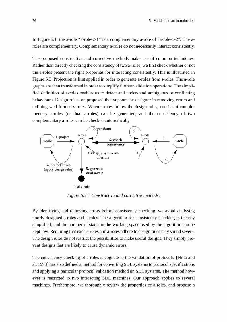
76 5 Validation: an introduction
In Figure 5.1, the a-role “a-role-2-1” is a complementary a-role of “a-role-1-2”. The a-
roles are complementary. Complementary a-roles do not necessarily interact consistently.
The proposed constructive and corrective methods make use of common techniques.
Rather than directly checking the consistency of two a-roles, we first check whether or not
the a-roles present the right properties for interacting consistently. This is illustrated in
Figure 5.3. Projection is first applied in order to generate a-roles from s-roles. The a-role
graphs are then transformed in order to simplify further validation operations. The simpli-
fied definition of a-roles enables us to detect and understand ambiguous or conflicting
behaviours. Design rules are proposed that support the designer in removing errors and
defining well-formed s-roles. When s-roles follow the design rules, consistent comple-
mentary a-roles (or dual a-roles) can be generated, and the consistency of two
complementary a-roles can be checked automatically.
By identifying and removing errors before consistency checking, we avoid analysing
poorly designed s-roles and a-roles. The algorithm for consistency checking is thereby
simplified, and the number of states in the working space used by the algorithm can be
kept low. Requiring that each s-roles and a-roles adhere to design rules may sound severe.
The design rules do not restrict the possibilities to make useful designs. They simply pre-
vent designs that are likely to cause dynamic errors.
The consistency checking of a-roles is cognate to the validation of protocols. [Nitta and
al. 1993] has also defined a method for converting SDL systems to protocol specifications
and applying a particular protocol validation method on SDL systems. The method how-
ever is restricted to two interacting SDL machines. Our approach applies to several
machines. Furthermore, we thoroughly review the properties of a-roles, and propose a
Figure 5.3 : Constructive and corrective methods.
s-role1. project a-role
4. correct errors
3. identify symptoms
2. transform
of errors
(apply design rules)
dual a-role
5. generatedual a-role
s-role1.
a-role
4.
3.
2.
5. checkconsistency

5.5 Interaction consistency 77
classification of anomalous behaviours that are symptoms for errors. These behaviours
can be identified at system design time.
The transformations applied to s-roles and a-roles are rather simple. They can be per-
formed manually by the designer, or be supported by tools. The design rules can also be
applied manually, and be enforced by design tools. It is our experience, and this is also
observed by [Logean and al. 1999], that the use of automated formal validation techniques
for industrial software design is still moderate. The current techniques require high com-
petence and knowledge in formal modelling and reasoning from the system developer. We
believe that our approach, although having a formal base, remains easy to understand and
use. In that way, the applicability of the proposed approach is wider than the validation in
a dynamic context. It should also be of interest for the validation of static systems.
5.5 Interaction consistency
Our work focuses on safety properties, i.e. bad things that should never happen. Unspec-
ified signal receptions, deadlocks and improper terminations are classified as violations
of safety properties. Liveness properties, i.e. desirable things that should eventually hap-
pen, are not addressed. We do not provide any formalism for expressing liveness
requirements as done in [Holzmann 1991].
As a-roles are defined in terms of state machines that communicate by message
exchanges, safety violations can be characterized in terms of signals and states. This sec-
tion defines the safety violations considered here.
The approach is restricted to the avoidance and detection of logical errors. Physical errors
such as signal loss, communication channel defect and actor defect are not discussed.
Definition: Unspecified signal reception
An unspecified signal reception occurs when an a-role receives a signal that is not speci-
fied as input in the current role state.
In SDL, unspecified signals are discarded, and thus unspecified signal reception may not
cause any immediate failure. However, unspecified signal reception is a symptom of pos-
sible design errors. Therefore we enforce strong requirements on interacting roles: all
signals sent by a role should be explicitly consumed by the associated role.

78 5 Validation: an introduction
Definition: Deadlock
A deadlock occurs when two a-roles are unable to proceed because they wait endlessly for
signals from each other.
Definition: Improper termination
Improper termination occurs:
- when two a-roles do not terminate in a coordinated manner: no signal should be sent to
an a-role that has terminated,
- when the exit conditions attached to the a-role terminations are not consistent. Two exit
conditions are consistent when they represent the same termination cases, or when one of
the conditions represents a termination case that covers the termination case represented
by the other condition.
The termination of an a-role should be perceived by the interacting a-role so that a-roles
never send signals to their associated complementary a-roles when they have terminated.
This requirement is essential to support consistent role composition.
SDL does not define the concept of exit condition, but the concept of exit label. An exit
label is a means for abstracting a condition. For example, the role “inviter” introduced in
Chapter 3 on page 33, is defined with two exit labels: “fail” and “success”. Each label rep-
resents a condition of termination. We prefer to reason on exit conditions rather than
labels. In Section 7.1.2.4 on 172, we will introduce an extension to the SDL exit label for
expressing exit conditions as OR-expression of other exit conditions. This extension facil-
itates the composition of roles across actors. For example, using this extension, it will be
possible to attach the condition “fail OR success” to a return node. The condition “fail OR
success” means any of the cases “fail” or “success”. It represents a termination case that
covers the termination case represented by the condition “fail”. Thus we consider the two
conditions “fail OR success” and “fail” to be consistent.
In the following, we will use the term exit condition instead of exit label. Similarly, we will
use entry condition instead of entry label.
Definition: Interaction consistency
A-roles are said to interact consistently when their interactions do not lead to any unspec-
ified signal reception, deadlock or improper termination.

5.6 Rules 79
5.6 Rules
In the following chapters, we will define various rules related to the validation of a-roles
and s-roles. We distinguish between three kinds of rules:
• D-rules, or design rules, define guidelines for the system designer. D-rules mainly
describe the desirable properties of a-roles and s-roles. Some of them facilitate inter-
face validation. D-rules apply to humans, and can be enforced by design tools.
• T-rules, or transformation rules, are related to the transformations that we define and
apply on the role state graphs. These transformations will aim to reduce the complexity
of the analysis, or to produce consistent complementary a-roles. T-rules apply to man-
ual or automated transformations.
• V-rules, or validation rules, support the validation of roles. They describe required
properties of roles, and the techniques that may be applied on these roles. V-rules apply
to humans, and can be enforced by design and validation tools.
The rules are expressed in simple terms so that they are easy to understand and apply.
However, we have tried to be precise, and we have provided a justification for each rule.
We also define algorithms for the main transformations and validation rules.

80 5 Validation: an introduction

- 81 -
6
Service association role modelling
This chapter introduces the modelling of service association roles (a-roles). Recall that an
a-role is defined as the visible interaction behaviour of an s-role on an association with
another s-role. We describe a-roles as state machines using a notation inspired from SDL.
As a-roles are restricted to the visible behaviour of s-roles on associations, full SDL is not
needed. Some extensions to the SDL notation are introduced in order to abstract non-
observable behaviours, i.e. s-role behaviours not visible at the interface.
The set of concepts needed for a-role modelling is first identified by describing the pro-
jection from s-roles to a-roles. The projection of an s-role state graph generates an a-role
state graph. Transformations are proposed that can be applied on a-role state graph in
order to facilitate interface validation. In particular a-roles will be described using transi-
tion charts, a kind of state graph where transitions between states consist only of a single
event: an input, an output or a silent event.
This chapter also identifies s-role patterns that lead to ambiguous or conflicting behav-
iours. An a-role behaviour is said to be ambiguous when an external observer is not able
to determine which behaviour is expected by this a-role. A conflict occurs when the
behaviours of an a-role and its complementary a-role diverge. Ambiguous and conflicting
behaviours require special consideration during interface validation.
6.1 Modelling concepts
A-roles capture the interaction behaviour of an s-role on an association. They abstract the
internal actions occurring in the s-roles and the interactions towards other s-roles. In order
to identify the concepts needed for a-role modelling, it is suitable to think about a-roles as
derived from s-roles. We call this derivation a projection. The projection of an s-role state
graph onto an association generates an a-role state graph.

82 6 Service association role modelling
A-roles exhibit the same behaviour as the s-roles they are derived from, on the association
they are attached to. This means that an s-role and the projected a-role should be able to
generate the same sequence of outputs on an association when offered the same sequence
of inputs on this association. Note that the s-role and the projected a-role are not restricted
to generate a single sequence of outputs for a given sequence of inputs; alternative
sequences are allowed. The behaviour determining the choice of a sequence is not visible
at the association interface, and an a-role may appear to make non-deterministic choices.
This non-determinism results from the abstraction of the s-roles internal decisions and the
interactions on other associations.
The relation between an s-role and a projected a-role is a kind of equivalence relation. The
notion of equivalence is usually introduced in program verification, and aims to establish-
ing the equivalence of a program and its specification. Several equivalence relations have
been proposed [Milner 1989]. These relations are based upon the concept of observable
behaviour: “two agents are equivalent, if they exhibit the same behaviour”, where several
interpretations may be given as to what behaviour is observable. In particular, the internal
actions may be observable or not. In our approach, the observation is restricted to one
association at a time, and the abstraction of internal actions is observed in terms of state
changes, where each state represents different behaviour events.
Definition: Observable association behaviour
The behaviour provided by an s-role on an association is called the observable association
behaviour.
We will also use the term external association observer, or simply external observer, to
denote some external machine that interacts with the s-role on an association. An external
observer perceives the signals sent by an s-role on an association. It can observe how an
s-role reacts, or responds, to the reception of a signal or sequence of signals. An external
observer does not observe s-role state changes directly, only indirectly when state changes
lead to distinct responses. A complementary a-role is a kind of external observer.
Figure 6.1 : A-role and external observer.
s-role
a-role
externalobserver
other associations

6.1 Modelling concepts 83
Sections 6.1.1 to 6.1.8 introduce the modelling concepts by describing the projection from
s-roles to a-roles. Similarly to s-roles, a-roles are described as state machines. A notation
inspired from SDL is introduced for the specification of a-roles. In Section 6.2, we will
show that the a-roles obtained by projection provide the same observable association
behaviour as s-roles.
6.1.1 Signals
We assume that all the communication between s-roles take place by the exchange of sig-
nals, and that signals exchanged on an association between two s-roles are conveyed
asynchronously on the same communication path. Communication is modelled using
SDL input signals and output signals. A communication path is constituted by a sequence
of connected channels. With this assumption, we ensure that signal ordering is preserved
during transport on an association, i.e. signals are received in the same order as they are
sent. Communication through remote variables and remote procedure calls is not
considered.
An association between two s-roles handles the signals that can be exchanged between
these two s-roles, and does not contain any other signalling. For each s-role, the associa-
tion includes the signals that can be received from the association, and the signals that can
be sent on the association.
Definition: Valid association input signal set
A valid association input signal set is defined with respect to an s-role and an association
related to this s-role. The valid association input signal set is the set of signals that can be
received by the s-role from the association.
Definition: Valid association output signal set
A valid association output signal set is defined with respect to an s-role and an association
related to this s-role. The valid association output signal set is the set of signals that can
be sent by the s-role to the association.
We assume that valid association input signal sets related to distinct s-role associations are
disjoint. We also assume that valid association output signal sets related to distinct s-role
associations are disjoint. In practice, signal sets can be made disjoint by encoding the ref-
erences to the entities involved in the association in the signal. These assumptions
facilitate the identification of the signals related to an association during the projection.

84 6 Service association role modelling
We will also use the terms visible signals and non-visible signals to denote signals that are
respectively exchanged and not exchanged on the association where a projection is done.
Given an association, a visible signal belongs to the valid association input and/or output
signal set. A non-visible signal does not belong to any of the sets.
An a-role state graph describes the sending and consumption of signals exchanged on the
association the a-role is attached to, i.e. the exchange of visible signals. The consumption
of signals from other associations by the s-role, i.e. non-visible input signals, may lead to
state changes that influence the further behaviour on the association the a-role is attached
to. These signals are abstracted from the a-role state graph and become SDL spontaneous
inputs. Their accurate identification is not relevant, the state changes are. Spontaneous
transitions are further explained in the next section. The signals sent on the other associ-
ations, i.e. non-visible output signals, have no influence on the state changes, and are not
represented in the a-role state graph at all.
6.1.2 States and transitions
While a state in the state graph of an s-role represents a condition in which a signal may
be consumed (recall the assumptions introduced in Section 3.3.1), a state in the state
graph of an a-role represents a condition in which signals may be consumed or sent.
The s-role states that represent conditions for the consumption of signals in the valid asso-
ciation input signal set, are projected to states that also represent conditions for the
consumption of these signals in the a-role. A simple state projection is shown in
Figure 6.3. The behaviour that is not visible at the interface, here signal sending on other
associations, like “X” and “Y”, is represented by a dashed symbol. This notation will be
also applied in the next figures.
The consumption of signals from other associations is projected to spontaneous transi-
tions in the a-role. The triggering of a transition without any signal consumption is defined
in SDL as a spontaneous transition, and is intended to represent non-deterministic behav-
iour. When modelling a-roles, a spontaneous transition indicates that some non-visible
Figure 6.2 : Visible and non-visible signals.
s-role
a-role
<non-visible signals on A> <visible signals on A>
A
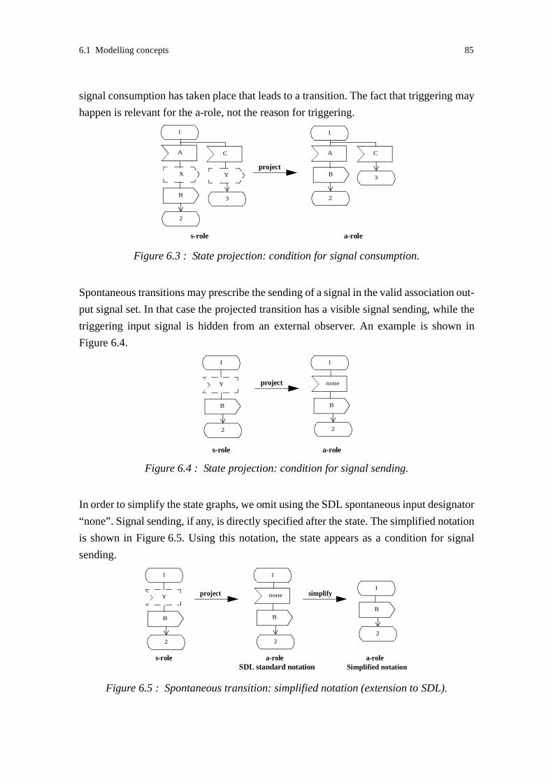
6.1 Modelling concepts 85
signal consumption has taken place that leads to a transition. The fact that triggering may
happen is relevant for the a-role, not the reason for triggering.
Spontaneous transitions may prescribe the sending of a signal in the valid association out-
put signal set. In that case the projected transition has a visible signal sending, while the
triggering input signal is hidden from an external observer. An example is shown in
Figure 6.4.
In order to simplify the state graphs, we omit using the SDL spontaneous input designator
“none”. Signal sending, if any, is directly specified after the state. The simplified notation
is shown in Figure 6.5. Using this notation, the state appears as a condition for signal
sending.
Figure 6.3 : State projection: condition for signal consumption.
1
A
X
B
project
a-role
1
A
B
s-role
C
Y
C
2
23
3
Figure 6.4 : State projection: condition for signal sending.
1
Y
B
project
a-role
1
none
B
s-role
2 2
Figure 6.5 : Spontaneous transition: simplified notation (extension to SDL).
SDL standard notation
1
Y
B
project
a-role
1
none
B
s-role
1
B
simplify
Simplified notationa-role
2 22
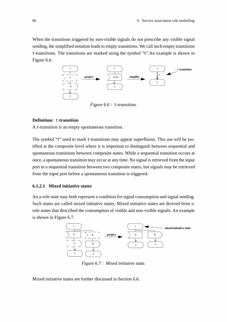
86 6 Service association role modelling
When the transitions triggered by non-visible signals do not prescribe any visible signal
sending, the simplified notation leads to empty transitions. We call such empty transitions
τ-transitions. The transitions are marked using the symbol “τ”.An example is shown in
Figure 6.6.
Definition: τ-transition
A τ-transition is an empty spontaneous transition.
The symbol “τ” used to mark τ-transitions may appear superfluous. This use will be jus-
tified at the composite level where it is important to distinguish between sequential and
spontaneous transitions between composite states. While a sequential transition occurs at
once, a spontaneous transition may occur at any time. No signal is retrieved from the input
port in a sequential transition between two composite states, but signals may be retrieved
from the input port before a spontaneous transition is triggered.
6.1.2.1 Mixed initiative states
An a-role state may both represent a condition for signal consumption and signal sending.
Such states are called mixed initiative states. Mixed initiative states are derived from s-
role states that described the consumption of visible and non-visible signals. An example
is shown in Figure 6.7.
Mixed initiative states are further discussed in Section 6.6.
Figure 6.6 : τ-transition.
1
Y
X
project
1
none
1
simplify
2
2
2
τ-transition
τ
Figure 6.7 : Mixed initiative state.
1
A
Y
project
1
A BX
B
mixed initiative state
3
32
2

6.1 Modelling concepts 87
6.1.2.2 Multiple transitions
An a-role state may enable the consumption or sending of multiple signals. In Figure 6.3,
several signals can be consumed in state “1”. In Figure 6.7, sending and consumption are
both allowed in state “1”. An a-role state may also prescribe the sending of multiple sig-
nals. An s-role state that prescribes the consumption of multiple signals from other
associations is projected to an a-role state that prescribes the sending of multiple signals.
An example is shown in Figure 6.8.
6.1.2.3 Implicit transitions
We retain the SDL semantics for the interpretation of transitions between states. A signal
received in a state that is not specified as input or save in that state, is implicitly consumed,
i.e. discarded.
According to our definition of interaction consistency (see Section 5.5), implicit transi-
tions should not occur, and is treated as an error in the validation analysis.
6.1.3 Internal actions
The internal actions of an s-role, such as tasks, agent instance creations or timer operations
are not visible at the interface. They are not represented in the a-roles. Thus an a-role tran-
sition is either empty, or it describes the sending of a visible signal or a set of signals.
Figure 6.9 illustrates the projection of an internal task.
Figure 6.8 : Sending of multiple signals.
1
X
A
project
1
BY
B
A
32
32
Figure 6.9 : Non-visible internal behaviour.
1
A
2
B
/* task */
1
A
B
2
project

88 6 Service association role modelling
6.1.3.1 Decision
A decision consists in a question and a set of answers, where these answers lead to differ-
ent behaviour choices. The processing of the question is an internal action that is not
visible at the interface. The answers also represent internal information. The choices, on
the other hand, may describe visible behaviours, e.g. the sending of a signal or a transition
to a new state. Such choices are described in the a-role.
In Figure 6.10, the decision choices describe internal behaviours; they are not represented
in the a-role.
In Figure 6.11, the decision choices describe the sending of signals in the valid association
output signal set. The choices are represented in the a-role, but not the decision. The deci-
sion is abstracted to a non-deterministic choice. Note that we introduce an extension to
the SDL notation: two transitions attached to the same input are normally not allowed.
In Figure 6.12, the decision choices describe transitions to new states; they are also rep-
resented in the a-role.
Figure 6.10 : Abstracting a decision node: internal behaviour.
1
A
1
A
2
B
project
/* task 1 */ /* task 2 */2
B
Figure 6.11 : Abstracting a decision node: before signal sending (SDL extension).
1
A
B C
2
1
A
3
B C
project
2 3
2
1
A
3
B C
simplify
any
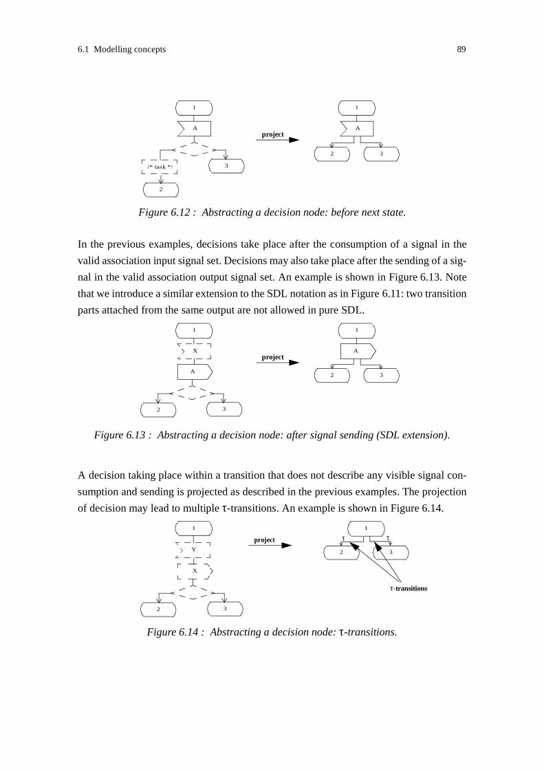
6.1 Modelling concepts 89
In the previous examples, decisions take place after the consumption of a signal in the
valid association input signal set. Decisions may also take place after the sending of a sig-
nal in the valid association output signal set. An example is shown in Figure 6.13. Note
that we introduce a similar extension to the SDL notation as in Figure 6.11: two transition
parts attached from the same output are not allowed in pure SDL.
A decision taking place within a transition that does not describe any visible signal con-
sumption and sending is projected as described in the previous examples. The projection
of decision may lead to multiple τ-transitions. An example is shown in Figure 6.14.
Figure 6.12 : Abstracting a decision node: before next state.
1
A
2
1
A
3
project
2 3
/* task */
Figure 6.13 : Abstracting a decision node: after signal sending (SDL extension).
1
A
1
X
A
project
2 3
2 3
Figure 6.14 : Abstracting a decision node: τ-transitions.
1
Y
X
project
2 3
τ-transitions
1
2 3
ττ

90 6 Service association role modelling
6.1.4 Initial states
An a-role initial state represents the start of interactions on an association. Initial states are
modelled in the a-role state graph using SDL start nodes. The SDL semantics for start
node is maintained.
A-role initial states are directly derived from s-roles initial states. S-role initial transitions
are projected in a similar way as other transitions. Recall that the consumption of signals
is not allowed in start nodes. An a-role initial transition is either an empty spontaneous
transition, i.e. a τ-transition, or it describes the sending of a signal or a set of signals.
An entry condition may be associated with an initial state. A state graph may contain sev-
eral initial states. In that case, distinct entry conditions should be associated to the initial
states. The projection maintains the entry conditions attached to the initial states.
6.1.5 Exit states
An a-role exit state represents the end of an interaction on an association. Exit states are
modelled in the a-role state graph using SDL return nodes. The SDL semantics for return
node is maintained.
A-role exit states are directly derived from s-roles exit states. An exit condition may be
associated to an exit state. The projection maintains the exit conditions attached to the exit
states.
6.1.6 Timer signals
Timer signals are projected to SDL spontaneous inputs similarly as for signals received
from other associations.
6.1.7 Save
A saved signal in SDL is not immediately consumed, but retained in the agent input port
for future processing. A saved signal is treated as a normal signal instance in the following
state. A saved signal is not necessarily consumed in the successor state. The input port
may contain several saved signals; signals are consumed in the order of their arrival.
The projection of save is complex. When the consumption of saved signals is combined
with spontaneous transitions, the activation of spontaneous transitions may occur before

6.1 Modelling concepts 91
the consumption of saved signals. The activation of a spontaneous transition may occur
at any time, independently of the presence of signals in the input port. In order to define
a simple projection of save that maintains the observable association behaviour, we pro-
pose to constrain the use of save. Constraints can be expressed by design rules.
This section first defines a simple projection of save and justifies this definition. Then,
non desirable behaviours occurring when combining the projection of save and spontane-
ous transitions are described. Finally we define design rules that enable us to apply the
simple projection of save. An alternative definition of the projection is also proposed that
relaxes the constraints set by the design rules.
6.1.7.1 Save projection: a simple definition
We would like to define the projection of save so that the saving of signals belonging to
the valid association input signal set is maintained in the a-role graph, while the saving of
signals received from other associations is not represented in the a-role graph. Intuitively,
this seems an acceptable definition. The information related to the saving of signals in the
valid association input signal set is of importance, as it influences the allowed ordering of
signal sending on the association. On the other hand, only the knowledge about state
changes triggered by the consumption of non-visible signals is relevant, not the identifi-
cation of these signals, and not the moment of their arrival. Spontaneous transitions model
that non-visible signals may be received at any time.
We first assume that the projection of save is defined in this simple way and present a set
of examples where the definition satisfies our requirement on observable association
behaviour.
Figure 6.15 illustrates the projection of the saving of a visible signal “B”. The saving of
signal “B” is maintained in the a-role graph. The machines behave in the same ways: the
s-role and a-role generate the same output when offered the same inputs; signal “B” can
be sent before or after “A”.
Figure 6.16 illustrates the projection of the saving of a non-visible signal “X”. The saving
of signal “X” is not represented in the a-role graph. The machines behave in the same
ways: an external observer that sends “A”, can receive “D”.
Figure 6.17 illustrates the projection of the saving of a visible signal “B” and a non-visible
signal “X”. Only the saving of signal “B” is maintained in the a-role graph. An external

92 6 Service association role modelling
observer may either send “A” before “B”, or “B” before “A”. In both cases, the two s-role
behaviours described in state “2” can occur, depending on whether the saving of “X” has
taken place before “B”, after “B” or not at all. An external observer either receives “C” or
“D”. The same two behaviours can also be observed when interacting with the a-role,
depending on whether the spontaneous transition occurs immediately when entering state
“2” or not.
Figure 6.15 : Projection of save: visible signal.
1
A
Y
project
1
A
2
2
B
B
C
3
B
B
C
3
Figure 6.16 : Projection of save: non-visible signal.
1
A
Y
project
1
A
2
2
X
X
D
D
3
3
Figure 6.17 : Projection of save signals: visible and non-visible signals.
1
A
Y
project
1
A
2
2
X B
X
B
D
B
B
C
4
C
3
4
D
3

6.1 Modelling concepts 93
In this last example, the independent arrival of “B” and “X” in the input port and their
retrieval are properly modelled by the spontaneous activation of the spontaneous transi-
tion. A spontaneous activation is however not always desirable. This is discussed in the
next section.
6.1.7.2 Interference between save and spontaneous transition
The save feature is often applied in order to enforce a strict ordering on the consumption
of signals on an association. When this use of save is combined with interactions on other
associations, the proposed projection of save does not always maintain the observable
association behaviour. The activation of spontaneous transitions in the projected a-role
may interfere with the retrieval of saved signals in an unintended way.
An example is shown in Figure 6.18. Here the interaction on the association carrying “A”
and “B” is combined with an interaction on another association. The visible signals “A”
and “B” may be sent in various orders, and the s-role handles them in the fixed order “A”
before “B”. When “B” is sent before “A”, “B” is necessarily the first signal in the input
port when entering state “2”. Thus the saving of “B” enforces the s-role to always handle
“B” before “X”. In that case, the s-role always sends “C”. The a-role however, may either
send “C” or “D” depending on the activation of the spontaneous transition that sends “D”.
Similarly, the s-role described in case (a) in Figure 6.19 and its derived a-role do no pro-
vide the same observable association behaviour. While the s-role fails to interact
consistently when “B” is sent before “A”: “C” (and anything) never happens, the a-role
may sometimes send “C” depending on the activation of the spontaneous transition. We
observe that the same a-role is obtained by projection of the s-role described in case (b).
Here however, the s-role and its derived a-role behave similarly. The saving and retrieval
Figure 6.18 : Projection of a save signal: an undesirable a-role behaviour (1).
1
A
Y
project
1
A
2
2
B
X
B
D
B
C
D
3
B
C
4
43

94 6 Service association role modelling
of “X” occur independently from the saving and retrieval of “B”. This is properly mod-
elled by the spontaneous transition.
Of course, the behaviours described in Figure 6.19 are not desirable. In both cases, “B”
may be discarded in state “2”. If the saving of “B” is introduced in state “2”, we observe
that the s-role and the projected a-role would provide an identical behaviour.
The interference between the spontaneous transitions and the retrieval of saved signals in
the input port invalidate the proposed projection of save. The projection does not always
maintain the observable association behaviour. The previous examples illustrate two
types of undesirable interferences:
• The spontaneous activation of a transition may prevent a saved signal from being dis-
carded from the input port. In some way, the interference partially repairs an incorrect
behaviour specification. This was shown in case (a) of Figure 6.19.
• The spontaneous activation of a transition may prevent a saved signal from being con-
sumed when it is stored first in the input port. This was shown in Figure 6.18.
While the first kind of interference is avoided by introducing a design rule enforcing a
consistent use of save, the second may either be avoided by the redefinition of the projec-
tion of save, or by a design rule constraining how save should be used.
Figure 6.19 : Projection of save signals: an undesirable a-role behaviour (2).
1
A
Y
project
1
A
2
2
B
X
B
Z
3
B
3
B
C
4
C
4
1
A
Y
2
X B
X
Z
3
B
C
4
project
(a) non-successfully projected (b) successfully projected
τ

6.1 Modelling concepts 95
6.1.7.3 Save consistency
The discarding of a saved signal from the input port is not desirable neither with respect
to the projection of s-roles nor with respect to the consistency of interaction between s-
roles. As our definition of interaction consistency requires that unspecified signal recep-
tion never happens (see Section 5.5), saved signals should eventually be consumed in the
state(s) succeeding a saving state.
D-rule: Save consistency
The saving of a signal should be repeated in the successor state(s) of the state where save
is specified until the consumption of the saved signal is specified. A successor state spec-
ified according to this rule is said to maintain save consistency, or to be save consistent
with its predecessor state(s). An s-role specified according to this rule is said to be save
consistent.
Note that the repetition of save may introduce new saving states. The successor states of
these new saving states should also be save consistent.
Using this rule, the two case examples shown in Figure 6.19, should be redefined. “B”
should be saved in state “2” in both cases. Then the projection of save faithfully maintains
the observable association behaviour.
The save consistency rule does not necessarily prevent the discarding of a saved signal
from occurring. In Figure 6.17, for example, the rule has been enforced, but still signal
“B” may be discarded in state “3”. In that case, rules related to mixed initiative states
should be applied. This will be explained in Section 7.1.3.
In the following, we assume that s-roles are designed according to the design rule "Save
consistency".
6.1.7.4 Retrieval of saved signals
The rule "Save consistency" addresses the problem of the discarding of saved signals, but
not that of retrieval as shown in Figure 6.18. We may consider two kinds of solutions to
the retrieval problem:
• One is to redefine the projection of the retrieval of a saved signal by adding control on
the activation of the spontaneous transition.

96 6 Service association role modelling
• Another is to constrain the use of save. Save is a complicating feature and should not
end up modelling both alternative orderings and concurrent association behaviours.
6.1.7.4.1 Controlling the activation of spontaneous transitions
Control can be set on the activation of a spontaneous transition by associating a precon-
dition to the activation. In SDL, preconditions can be expressed using continuous signals.
Figure 6.20 illustrates this approach. The precondition only depends on the interaction on
the association where the projection is done. “B not sent before A” means that B is not
saved. Note that in the case where “B” is sent after “A”, both transitions in state “2” of the
the projected may also occur. According to the SDL semantics, signals in the input port
are retrieved before continuous signals are interpreted when entering a new state.
Preconditions should only be applied in the case where the non-visible signals projected
to spontaneous inputs may interfere with the retrieval of a saved signal in an undesirable
way. In the case where non-visible signals can be stored in the input port before the visible
saved signal, preconditions should not be added. For example, in Figure 6.17 the non-vis-
ible signal “X” may be saved before “B”. Preconditions are not needed in that case.
In this approach, preconditions are defined by comparing the possible ordering of the sig-
nals sent by the complementary a-role. The ordering of two signals, one sent and one
received cannot be compared. As communication between a-roles is asynchronous, the
reception of a signal is perceived some time after its sending, and a complementary a-role
is not able to determine when the sending of a signal exactly occurs. In Figure 6.21, an
external observer cannot determine whether “B” is received before or after sending “C”.
Figure 6.20 : Projection of a save signal: using a continuous signal.
1
A
Y
project
1
A
2
2
B
X
B
E
3
B
C
4
E
3
B
C
4
B not sentbefore A

6.1 Modelling concepts 97
To sum up, preconditions should be defined for each visible signal that is saved in a state
that can consume a visible signal when:
• The saved signal can be retrieved in a state that can consume non-visible signals.
• These non-visible signals cannot be not saved before the visible saved signal.
Preconditions control the triggering of the transitions projected from the transitions trig-
gered by these non-visible signals. They describe the ordering of a pair of visible events
(saved signal, consumed signal).
When several visible signals can be saved in the same state, preconditions should be
defined for each pair of signals (saved, consumed). The preconditions should be logically
combined such that any possible ordering combination is described. Such a case is how-
ever a symptom of complex - and possibly bad - design, and should be avoided.
6.1.7.4.2 Constraining the use of save
The refined projection of save defined in Section 6.1.7.4.1 is rather simple. However hav-
ing in mind that the save concept introduces complexity, we propose to introduce
constraints on using save.
Figure 6.21 : Projection of save signals: comparing signal ordering.
1
A
Y
2
BX
C
3
The order of occurrence of “B” and “C”
Z
D
3
B
E
4
cannot be observed.

98 6 Service association role modelling
Save serves two main purposes:
• It may be used to enable alternative signal sending orderings while a strict order on the
consumption of signals is enforced. Seen from the complementary a-role, the ordering
of signal sending is relaxed.
• It may be used to facilitate the description of concurrent behaviours on multiple asso-
ciations. For example, save may be used to enable an interaction on an association not
to be interrupted by the arrival of signals from other associations.
In order to limit the complexity of a design, we advise not to use save to relax the ordering
of signal sending. Alternative orderings should only be specified when required for opti-
misation purposes, or when constrained by external interfaces. Furthermore, we
recommend not to combine the use save for alternative orderings together with the
description of concurrent behaviours. This constraint applies both when the modelling of
concurrent behaviours involves save or not.
In Figure 6.18, save is used to describe alternative sending orderings. This use of save
overlaps with the description of a concurrent behaviour: “X” can be received when “B” is
retrieved. The s-role should be re-designed, avoiding the saving of “B”. The constraint on
the usage of save will permit to generate a projection that provides an identical observable
association as the s-role.
In Figure 6.17, save is used to describe alternative sending orderings and concurrent
behaviours: both “X” and “B” are saved. The s-role should be re-designed. Although it is
possible in that case to generate a projection that provides an identical observable associ-
ation as the s-role, the s-role behaves in a non-deterministic manner.
D-rule: Save and ordering
Using save for the modelling of alternative signal orderings on one association should be
restricted to special cases, for example when required for optimisation purposes, or when
constrained by external interfaces.
Alternative orderings can easily be identified: a state that can both save and consume sig-
nals received from the same association models alternative orderings.
D-rule: Ordering with save and concurrency
Using save for the modelling of alternative signal orderings on one association should not

6.1 Modelling concepts 99
overlap with the modelling of concurrent behaviours.
Overlapping can easily be identified: a signal saved in a state that can consume signals
from the same association, should not be retrieved in a state that can consume signals from
other associations. When this rule is enforced, the projected a-role does not describe any
spontaneous transition in the state where the saved signal is retrieved. Thus interferences
between spontaneous transitions and the retrieval of a saved signal do not occur.
The rules do not constrain the use of save for modelling concurrency when no alternative
orderings are described. Saved signals not involved in alternative orderings may be
retrieved in any state, also states receiving signals from other associations. In this way, it
is possible to describe complex concurrent behaviours that occur on three associations or
more. This is illustrated by Figure 6.22. Here the s-role provides three association roles
“A-1”, “A-2” and “A-3”. The s-role is first involved in an interaction on “A-3”; any of the
other associated roles may send the role a request “A” or “K”. When the interaction on
“A-3” is finished (in state “2”), the s-role handles one of the requests, possibly the request
that was first saved, if any.
In the case where a spontaneous transition occurring in the retrieval state does not intro-
duce any visible behaviour (i.e. the sending of a visible signal), the rule "Ordering with
save and concurrency" may be too strict. An example is shown in Figure 6.23. The behav-
iour described by state “2” is not allowed by the rule. As the spontaneous transition does
not introduce any visible behaviour, this case is acceptable. We have chosen to maintain
the rule as already defined. The case of Figure 6.23 may be considered in further work.
Note that this kind of behaviour would be removed by state gathering (Section 6.3.2).
Figure 6.22 : Save and concurrent behaviours.
1
X
Y
2
A
A
L
3
K
B
4
K
s-role
L
K
A
B
X Y
A-3
A-1
A-2

100 6 Service association role modelling
In the following, we assume that s-roles are designed according to the design rule "Order-
ing with save and concurrency". When this rule is enforced, interferences between
spontaneous transitions and the retrieval of a saved signal do not occur. The initial defini-
tion of the projection of save can then be used. Justifying that the observable association
behaviour is maintained through the projection is further discussed in Section 6.2.
In the following, we assume that the simple projection of save defined in Section 6.1.7.1
is used.
6.1.8 Enabling condition
We have assumed that communication between elementary s-roles take place through sig-
nal exchange. Thus enabling conditions are not used to describe any information
exchange between s-roles. They represent local conditions that are set before entering the
state that the enabled conditions apply to. The graph can be transformed by replacing the
enabling condition with a decision. This is shown in Figure 6.24. The transformation does
not modify the s-role behaviour. Here the enabling condition is set on the consumption of
a visible signal. It could also be set on the consumption on a non-visible signal. Using such
transformation, it is not necessary to define the projection of local enabling conditions.
The graph can be transformed before projection. In the following, we will assume that the
s-role graph has been transformed in order to remove enabling conditions.
Enabling conditions that describe information exchange between s-roles are more com-
plex. They may lead to implicit signal saving. The conditions may change after entering
the state that describes the enabling condition. They are not considered.
Figure 6.23 : Design rule "Ordering with save and concurrency": a restricting case.
1
A
Y
not allowed in the same state2
B
X
Z
2
B
C
4

6.2 Projection and observable association behaviour 101
6.2 Projection and observable association behaviour
Section 6.1 has proposed a set of projection operations that transform s-roles to a-roles.
As the main purpose of a-roles is to validate the interaction behaviour of an s-role with
other s-roles, it is essential that the a-roles obtained by projection provide the same
observable association behaviour as the s-roles. An a-role should be able to generate the
same sequences of outputs on an association as the s-role it is derived from, when offered
a sequence of inputs on this association.
When comparing the s-role behaviour with a particular a-role behaviour, we assume that
any behaviour described by the s-role on the other associations may occur, i.e. any non-
visible input signal may be received, and any behaviour triggered by non-visible input sig-
nals may occur.
6.2.1 Simple behaviour: no signal saving
Let us first reason assuming that save is not used in the s-role state graph, i.e. signals are
consumed or discarded in the order of their arrival.
The projection transformation presented in Section 6.1 has the following properties:
• The projection maintains the structure of the state graph. Distinct states in the s-role
state graph are projected to distinct states in the a-role state graph. The transitions
between states are maintained, and no new transitions are added in the projected a-role
Figure 6.24 : Local enabling condition: graph transformation.
1
A
E
F
4
X
2
localcondition
B
D
3
1
A
E
F
4
X
2a
B
D
3
2b
E
F
4
transform localcondition

102 6 Service association role modelling
state graph.
• The projection maintains the valid association input and output signal sets. The a-role
is able to receive and send the same signals as the s-role on the association.
• The projection maintains the triggering of transitions by the consumption of a signal in
the valid association input set. The projected states can consume the same signals from
the association as the s-role states. No signal consumption is added in any projected
state.
• The projection hides non-visible signals, but transitions and state changes triggered by
non-visible signals are maintained. A spontaneous transition obtained from the projec-
tion of the triggering by the consumption of a non-visible signal may occur, in a similar
way as the transition in the s-role may occur when the non-visible signal is received
and consumed.
• The projection maintains the sending of signals on the association in transitions
between identical states. The transitions where signal sending on the association occurs
are transformed to transitions where identical sending occurs.
A projected state is triggered by the same set of visible input signals as the initial state it
is derived from, or by hidden non-visible signals. Thus each projected state may be trig-
gered in a similar way as its initial state. Each triggered projected transition may generate
the same outputs on the association, and lead to a new projected state that may also be
triggered in a similar way as its initial state and, again, the triggered transitions behave as
in the initial graph. Thus all association behaviour sequences described in an s-role graph
are also described in an a-role graph. As the projection does not introduce new state trig-
gers or transitions, no new behaviour sequences are introduced.
As long as the concept of save is not used, it is not possible to force a signal to be first in
the queue when entering a state. The signals are retrieved from the input port in the order
of their arrival. The immediate activation of a spontaneous transition in an a-role occurs
in the same way as the corresponding transition in the s-role when the non-visible signal
is stored before a visible signal in the s-role input port.
Thus, a-roles and s-roles represent the same interface behaviour included eventual errors.

6.2 Projection and observable association behaviour 103
6.2.2 Adding save
Let us now add the save concept. We assume that the design rules "Save consistency" and
"Ordering with save and concurrency" have been applied. The simple projection of save
defined in Section 6.1.7.1 is used.
As previously, the projected states provide the same set of transitions as the initial states
they are derived from. We have to consider how signal saving influences the triggering of
a transition. Using save, it is possible to control, or partially control, the ordering of sig-
nals in the input port when entering a new state. The design rule "Ordering with save and
concurrency" enforces that using save for alternative signal orderings does not overlap
with concurrent behaviours.
We first consider that save has been used to describe alternative orderings on the associ-
ation where the projection is done. The design rule "Save consistency" enforces the saved
signal (s) to be maintained in the input port until a state is reached where it (they) can be
consumed. The design rule "Ordering with save and concurrency" enforces that non-vis-
ible signals are not received in such a state, and thus the visible signals are retrieved as
enforced by the save ordering. The projected a-role describes the same behaviour: the pro-
jected state does not describe any spontaneous transition that can interfere with the
retrieval of a visible saved signal.
Let us now consider that save has been used in the modelling of concurrent behaviours.
This means that visible and non-visible signals can be saved and consumed in overlapping
states. Following the design rule "Ordering with save and concurrency", an external
observer cannot perceive when a visible signal is saved with respect to the occurrence of
other visible signals, and then cannot force a saved signal to be stored first in the input
port. A saved signal may be retrieved in any state. This retrieval may occur in a state when
only visible signals are retrieved, or in a state where other non-visible signals are retrieved
concurrently. The projected a-role describes the same interface behaviour as the s-role in
both cases.
From this reasoning, we deduce that projected a-roles provide the same observable asso-
ciation behaviour as s-roles, provided that the design rules "Save consistency" and
"Ordering with save and concurrency" are enforced.

104 6 Service association role modelling
6.3 A-role state graph refinement
The state graph obtained by projection may be transformed in order to simplify interface
validation. Reasoning on transition charts rather that state graphs will facilitate the gener-
ation of consistent complementary a-roles and other validation operations (see Chapter 7).
Section 6.3.1 defines transition charts, and describes the transformation from a-role state
graphs to transition charts. Section 6.3.2 and Section 6.3.3 define transformations for
reducing the size of the graph.
6.3.1 Transition charts
A transition graph is a kind of state graph where transitions between states are attached a
single event: an input, an output or a silent event. The event attached to a transition is said
to trigger the transition. Signal sending is not considered as an action occurring within a
transition, but rather as a triggering output event for a transition.
Definition: τ-event
τ-transitions are triggered by a silent event called the τ-event.
A transition chart is a particular state graph, and the notation defined for modelling a-role
state graphs can also be used to describe transition charts. Notice that, using the simplified
notation for spontaneous transitions, signal sending appears as a triggering output event
of a spontaneous transition (see Figure 6.5 on page 85).
In the case where every signal sending described in an a-role state graph occurs in a spon-
taneous transition (i.e. signal sending is never described in a transition triggered by the
consumption of a visible signal), and signal sending never succeeds any other signal send-
ing within a transition, the a-role state graph is a transition chart. Otherwise, the a-role
state graph has to be transformed to a transition chart. The transformation consists in
inserting a new state before signal sending, when the sending is not described as the first
action of a spontaneous transition.
An a-role transition chart should exhibit the same behaviour as the initial a-role state
graph derived from an s-role state graph. The insertion of a state before signal sending
should not modify the observable association behaviour. To that end, we introduce a new
kind of state: the σ-state.

6.3 A-role state graph refinement 105
6.3.1.1 σ-state
Definition: σ-state
A σ-state is a specialization of the SDL state that implicitly saves all signals in the valid
association input signal set. σ-states do not define any input event or τ-event. At least one
of the output events described in a σ-state always occurs.
The transformation of an a-role state graph to a transition chart is performed by inserting
a σ-state before the sending of a signal, when no state already precedes signal sending. A
transition part is added between the event preceding the signal sending and the σ-state.
Figure 6.25 illustrates the insertion of a σ-state. A naming convention is introduced in
order to distinguish σ-states from other states: the prefix “σ-” is added to the σ-state
names. The saving symbol is normally not represented in the a-role chart; it is shown here
to underline the implicit saving.
The σ-state insertion is performed on a-role state graphs after the projection from s-roles.
For this reason, it is possible to restrict saving to signals in the valid association input sig-
nal set. Signals received from other associations are not described in a-role state graphs.
As σ-states are inserted before the sending of signals, we can restrict input events and τ-
events not to happen in σ-states. Differently from other states, output events do not occur
spontaneously. There is no non-determinism in the occurrence of the events described in
a σ-state. When a σ-state is entered, one of the events described in the state always occurs.
The implicit saving of signals enables the transformed machine to handle the input signals
as the initial machine. Assume that the machine described in Figure 6.25 receives a signal
in the valid association input signal set during the transition between the states “1” and
“2” in the initial machine. The signal is handled in state “2”. After the insertion of the σ-
state, the signal may either be received between the states “1” and “σ-0”, in the state “σ-
Figure 6.25 : σ-state insertion.
1
A
X
B
project
1
A
B
*
implicit saving
2
2
1
A
B
2
σ-0
insert
will occur ifσ-0 i entered

106 6 Service association role modelling
0” or between the states “σ-0” and “2”. In the two first cases, the signal is saved in the σ-
state, and handled in state “2”. In the later case, the signal is handled in state “2”.
Furthermore, as the output signal in the σ-state always occur, we observe the same behav-
iour before and after the insertion of the σ-state in this example.
Figure 6.26 illustrates the insertion of a σ-state in a state graph that describes a non-deter-
ministic choice. In that case, we observe that the transformed machine also handles the
input signals as the initial machine as the initial machine. Assume that a signal in the valid
association input signal set is received during the transition between state “1” and one of
its successor states “2” or “3” in the initial machine. The signal is retrieved from the input
queue when one of these successor states is entered. After the insertion of the σ-state, the
signal may be received between the state “1” and one of its successor states “σ-0” or “3”,
or while in state “σ-0” or between the states “σ-0” and “2”. Because of implicit saving in
the state “σ-0”, a signal received before entering the state “σ-0”, in state “σ-0” is then
retrieved from the signal queue in state “2”. Similarly as in the initial machine, the signal
is either retrieved in the state “2” or “3”.
T-rule: σ-state insertion
σ-states are inserted before signal sending, when no state immediately precedes the signal
sending. After the insertion of a σ-state, a state machine exhibits the same behaviour as
the original machine.
Justification:
A transition where no σ-state is inserted may be triggered in the same way as in the initial
machine, and behave similarly.
A transition where some σ-state is inserted, may be triggered in the same way as in the
initial machine. It also behaves similarly:
- A signal sent in the transition before σ-state insertion (in a sending action) is also sent
Figure 6.26 : σ-state insertion after a non-deterministic choice.
1
A
B
2
1
A
3B
project
2
3
1
A
B
2
3σ-0
insert

6.3 A-role state graph refinement 107
in the sequence of transitions after σ-state insertion (as a triggering output event). There
is no non-determinism in the occurrence of the event.
- The signals stored in the signal queue when triggering the transition or received during
the transition before σ-state insertion, are handled in the same way after σ-state insertion:
they are retrieved from the queue in the same states, this because of the implicit saving.
In the following, we will assume that the a-role state graphs are transformed by σ-state
insertion to transition charts.
6.3.1.2 Initial states
In order to be able to treat initial states in a similar way as other states in the generation
of consistent complementary a-roles (see Chapter 7), we also introduce σ-states between
initial states and signal sending. After this transformation, all initial transitions are
described as empty transitions. Figure 6.27 illustrates the insertion of an σ-state after the
initial state.
Observe that the empty transitions after initial states differ from τ-transitions. The is no
non-determinism in the occurrence of an empty transition, i.e. an empty transition always
occurs.
T-rule: σ-state insertion in initial transitions
σ-states are inserted between initial states and signal sending. After the insertion of a σ-
state in an initial transition, a state machine exhibits the same behaviour as the original
machine.
Justification:
The original empty transitions from the initial state(s) remain unchanged, and may be trig-
gered at any time in the same way as in the original machine.
The empty transition before the inserted σ-state may occur at any time; it does not require
any external triggering. The inserted σ-state supports the same signal sending as the orig-
Figure 6.27 : σ-state insertion in an initial transition.
A
1
σ−0A
1
insert

108 6 Service association role modelling
inal initial state. Thus the transformed initial transitions provide the same sending
behaviour as in the original transitions.
The implicit signal saving enforces that signals received during the initial transitions are
handled in the same way (i.e. retrieved in the same states) as before the σ-state insertion.
In the following, we will assume that the a-role state graphs are transformed adding σ-
states between initial states and signal sending.
6.3.2 State gathering
The transformation from s-roles to a-roles may lead to graphs where several τ-transitions
follow each other successively. In some cases, these τ-transitions have no influence on the
observable association behaviour. Gathering is a transformation that merges states linked
by τ-transitions by a single state, and, in that way, reduces the size of a transition chart.
Gathering will be defined such that the transition chart transformed by gathering exhibits
the same behaviour as the initial transition chart. Before proposing a definition, this sec-
tion discusses examples where states can be gathered and examples where states cannot
be gathered.
We will use the term τ-successor to denote the successor of a state triggered by a τ-event,
and τ-predecessor to denote the predecessor state of a τ-successor.
6.3.2.1 Successive τ-transitions
An external observer cannot distinguish multiple successive τ-transitions from a single τ-
transition. This is illustrated by Figure 6.28. An external observer cannot distinguish the
τ-transition state “1” to state “2” from the τ-transition state “2” to state “3”. The states “1”
and “2” are gathered to “1-2”. The new state machine behaves like the initial machine.
The non-deterministic occurrence of the τ-transition is preserved.
6.3.2.2 Output behaviour
An external observer cannot distinguish whether a signal sending in a spontaneous tran-
sition occurs following a τ-transition or not. This is illustrated in Figure 6.29. An external
observer does not perceive the τ-transition between the states “1-2” and “3”. The states
can be gathered without modifying the a-role behaviour. The new state machine behaves
just as the initial machine. The non-deterministic occurrence of the output event is
preserved.

6.3 A-role state graph refinement 109
Gathering may also be applied to a τ-successor in a choice as illustrated by the two cases
in Figure 6.30. In case (b), state “1” can be gathered with the two τ-successors in the two
choices. In both cases, the new state machine behaves similarly as the initial machines.
The non-deterministic occurrence of the sending is preserved. Whether the signals “A”
and “B” are sent from distinct states or not, does not influence the observable association
behaviour.
Figure 6.28 : Gathering: successive τ-transitions.
1
V
project
1
gather22
W
X
3
Y
A
3
A
1-2
3
A
4
4
4
Z
B
5
B
5
B
5
τ
ττ
Figure 6.29 : Gathering: output behaviour.
1-2
3
A
gather 1-2-3
A
4
4
B
5
B
5
τ
Figure 6.30 : Gathering and choice (1).
gather
A
1
2 B A
1n
B
A
1
2 3
B
gather
4
5 4 5
54
(a) (b)
τ τ τ

110 6 Service association role modelling
The behaviour taking place after the gathered states remains unchanged. The same suc-
cessor states are specified. In Figure 6.31, the two transitions triggered by “A” lead to
different states. After gathering, two transitions leading to different states are specified.
6.3.2.3 Input behaviour
In the case where a τ-successor is triggered by one or more input events, gathering can be
applied if the τ-predecessor is triggered by the same set of input events, and if, for each
input event, the transitions lead to equivalent states, i.e. states that exhibit the same
observable behaviour. In order to simplify the definition of gathering, we propose to
restrict gathering to states that describe the same input behaviour, i.e. the states should be
able to consume the same signals and make transitions leading to identical states. This
restriction will be justified in Section 6.3.3.2 on page 121.
Definition: Input behaviour
The input behaviour of a state describes the set of input signals consumed by the state, and
for each input, the successor state(s) triggered by this input.
In case (a) shown in Figure 6.32, the states “1” and “2” describe the same input behaviour:
they both can consume signal “B”, and triggering by “B” leads to the same state, state “3”.
After gathering, the machine behaves similarly. In case (b), the states “1” and “2” cannot
be gathered. While signal “B” is discarded when received in state “1”, it is consumed in
state “2”. Note that, in case (a), there is no observable non-determinism on the association
before gathering. The machine can always consume “B”.
6.3.2.4 Mixed input and output behaviours
In the case where a τ-successor is triggered by output and input events, gathering can be
applied if the τ-predecessor defines the same input behaviour. An example is shown in
Figure 6.33. Here state “2” is both triggered by an input event and an output event. As
Figure 6.31 : Gathering and choice (2).
gather
A
1
2 A A
1n
A
A
1
2 3
A
gather
4
5 4 5
54
τ τ τ

6.3 A-role state graph refinement 111
states “1” and “2” describe the same input behaviour, they can be gathered. The new state
“1-2” is able to send the same output as the states before gathering.
Note that, in that the non-deterministic occurrence of the output event “A” is preserved by
gathering.
A τ-successor and a τ-predecessor that define distinct input behaviours cannot be gath-
ered. In Figure 6.34, states “1” and “2” cannot be gathered. While signal “B” can be
consumed in state “1”, it is discarded in state “2”. If states “1” and “2” were gathered, the
reception behaviour would be modified; this is not desirable.
Figure 6.32 : Gathering: input behaviour.
1
2
B
3
(b) distinct input behaviours:no gathering
gather
1
2
B
B
3
3
1-2
B
3
(a) same input behaviour
τ τ
Figure 6.33 : Gathering: mixed input/output behaviour.
gather
A
1
2
B
B
4
43
A
1-2
B
43
τ
Figure 6.34 : Gathering: distinct input behaviours.
A
1
2 B
4
3
distinct input behaviours:no gathering
τ

112 6 Service association role modelling
6.3.2.5 Save behaviour
We extend the previous examples by adding save behaviour. Providing the same condi-
tions as in the previous examples, a τ-successor can be gathered with its predecessor when
the states describe the same save behaviour, i.e. they are able to save the same signals.
Definition: Save behaviour
The save behaviour of a state describes the set of signals that can be saved by the state.
This is illustrated by Figure 6.35. The A states “1” and “3” describe the same save behav-
iour; hence they can be gathered. The non-deterministic occurrence of the sending of “B”
is preserved. On the other hand, the states “1” and “2” cannot be gathered because while
signal “C” is saved when received in state “1”, it is discarded in state “2”. According to
the design rule "Save consistency", this should not occur. The saving of “C” should be re-
iterated in state “2” or “C” should be consumed in state “2”.
Similarly, we can gather the states “1” and “2” in Figure 6.36. The states describe the
same input behaviour. Both can consume “A” and triggering leads to the same state. Both
states describe the same save behaviour.
The rule "Save consistency" enforces successor states to be defined consistently with their
predecessors, but not conversely. Two case examples are shown in Figure 6.37. An exter-
nal observer cannot distinguish state “1” from its τ-successor, and thus cannot determine
Figure 6.35 : Gathering: output and save behaviours.
gather
A
1
2 3
B
C
C A
1n
2 B C
4 5 4
5
identical savebehaviour
non -save consistent
state
τ τ τ
Figure 6.36 : Gathering: input and save behaviours.
gather1
2 A
3
B
1-2
A
3
τ
B A
3
B

6.3 A-role state graph refinement 113
when the signal “B” can be saved or not. We call this kind of behaviour “save ambiguity”.
The states cannot be gathered. While signal “B” can be saved in state “2”, it is discarded
in state “1”. Gathering would modify the reception behaviour; this is not desirable.
Definition: Save ambiguity
A save ambiguity occurs when, at some stage of an interaction, an external observer can-
not determine from any observable events that a signal can be saved by the a-role state
machine. The behaviour of the a-role is said to present a save ambiguity, or to be save-
ambiguous.
6.3.2.6 Distinct input and save behaviours
In the previous examples, the τ-successors and τ-predecessors being gathered have
described identical input behaviours and identical save behaviours. When the states
describe the same input and save events, but distinct behaviours, we fail to gather them
without changing the observable behaviour.
This is illustrated in Figure 6.38. The states “1” and “2” defines the same events “A” and
“B”. If we assume that the τ-transition always occurs, an external observer of the machine
(a) cannot perceive when the transition from “1” to “2” occurs, and cannot determine
whether or not signals are saved in state “1” before being consumed in “2”. When gather-
ing is applied as shown in (b), the signals may be consumed in the same way (storing a
signal in the input port also occurs when a signal is received while a transition is being
executed). However, as long as we cannot ensure that the τ-transition always occurs, gath-
ering cannot be applied. The behaviours before and after gathering are different. The
signal “A” sent to the machine (a) in state “1” may remain in the input port for ever, this
is a deadlock case. On the other hand, the signal would be consumed in case (b) and trig-
gering occur. The same reasoning also applies to show that behaviours differ when an
input signal is added (for example “C” shown in dash line).
Figure 6.37 : Gathering: save ambiguity.
1
2
B
3
A A
1
2
B
3
(a) (b)
save ambiguity:no gathering
save ambiguity:no gathering
A
3
τ τ

114 6 Service association role modelling
In Figure 6.39, the save and input states have been permuted. If we assume that the τ-tran-
sition and the sending of “B” always occur, an external observer cannot distinguish
between the machines (a) and (b). In (a) an external observer cannot determine when the
transition from “1” to “2” occurs, and whether the signal “A” will be consumed in “1”, or
saved in “2” and then consumed in “4”. In (b), as machines communicate asynchronously,
an external observer cannot observed when the sending “B”, if any, takes place. An
observer cannot determine whether the signal “A” is consumed in “1-3” or “4”. However,
as long as we cannot ensure that the τ-transition and the sending of “B” always occur,
gathering cannot be applied. Note that if we assume that the τ-transition occurs, but not
the sending of “B”, the machine (a) deadlocks in state “3”. The machine (b) does not dead-
lock with the same condition on “B”: it always can consume “A”.
In resume, in these two examples, gathering can be applied without changing the
machines observable behaviour provided that the spontaneous transitions, i.e. the τ-tran-
sitions and transitions triggered by output events, always occur.
6.3.2.7 Ordering behaviour
Even when the assumption that the spontaneous transitions always occur is made, gather-
ing cannot be always applied to a machine that defined the same input and save events.
Figure 6.38 : Gathering and non-determinism (1).
can occur
1
2
A
3
A
B
4
B
1-2
A
3
B
4
τ
(a) initial machine (b) after gathering
C
5
C
5
Figure 6.39 : Gathering and non-determinism (2).
3
1
A2
A
B
4
1-3
2
A B
4
τ
(a) initial machine (b) after gathering
can occur

6.3 A-role state graph refinement 115
This is the case when a τ-successor and its predecessor describe distinct ordering
behaviours.
This is illustrated in Figure 6.40. In both machines, an external observer that sends the sig-
nal sequence “B” followed by “A”, may either observe that “A” is handled first or “B” is
handled first. This depends on the state in which the machine is when receiving the sig-
nals. When “1” and “2” are gathered, the first behaviour, i.e. “A” first, is removed. The
observable behaviour is modified.
6.3.2.8 Definitions
We propose two definitions of gathering: strong and weak gathering. Strong gathering
maintains the machine observable behaviour. It is defined taking into account that τ-tran-
sitions may not occur. Weak gathering only maintains the observable behaviour provided
that spontaneous transitions can occur. Thus cases similar to those introduced in
Section 6.3.2.6 will be simplified by weak gathering, but not by strong gathering. Strong
gathering is safe. Weak gathering may hide some error behaviours that occur following
errors of the non-visible behaviour. This will be further discussed in Section 7.1.4 and
Section 7.3.
6.3.2.8.1 Strong gathering or gathering
Definition: Strong gathering (gathering)
Strong gathering or gathering is a transformation that applies to non-exit states. Gathering
merges two states that are linked by a τ-transition, i.e. a τ-successor and its τ-predecessor,
to a single state provided that:
- The τ-successor and τ-predecessor define the same input behaviour.
- The τ-successor and τ-predecessor define the same save behaviour.
The new state describes any spontaneous transitions defined for the non-gathered states,
except the τ-transition being gathered. It provides the input behaviour and save behaviour
Figure 6.40 : Gathering and ordering.
2
1
B
4
B
3
A 3
A
enforces ordering“A” before “B”
τ
2
1
B 4
B
3
A 3
A
τ
(a) (b)

116 6 Service association role modelling
of the states before gathering. In the transition graph, the transitions to a τ-predecessor
state merged by gathering, are replaced by transitions to the new state obtained by
gathering.
Notice that:
• Gathering is never applied to σ-states. σ-states never succeed or precede τ-transitions.
• Gathering is never applied to initial states. Initial states never precede τ-transitions, but
empty transitions.
• Gathering is not applied when a τ-transition links a non-exit state to an exit state.
Whether termination takes place immediately after some interaction on the association
has occurred or not, is of importance when roles are composed.
• Gathering is applied iteratively when a transition chart describes a sequence of τ-tran-
sitions or choices. As illustrated by Figure 6.28 and Figure 6.29, or Figure 6.30, states
“1” and “2” are first gathered; then the new state and state “3” are gathered.
• A state obtained by gathering may define τ-transitions. In Figure 6.35, the transition
between “1n” and “2” is a τ-transition.
After gathering, the τ-predecessor states are removed from the state graph because they
are no longer reachable from the initial states. τ-successor states, on the other hand, cannot
always be removed from the state graph. This is the case when a τ-successor is reachable
from other states through a non τ-transition. An example is shown in Figure 6.41. Gath-
ering is a transformation that suppresses τ-transitions rather than τ-successors from the
state graph. τ-successor states that are no longer reachable from the initial states, can be
removed applying Algorithm 7.5 on page 167.
Figure 6.41 : Gathering and state removal.
gather
C
34
DD
6 65
C
3-4
D
55
2
B
1
A
2
B
3
D
6
1
Aremoved by gathering
τ
not removedby gathering
6.3 A-role state graph refinement 117
T-rule: Strong gathering
After strong gathering or gathering, a transition chart exhibits the same observable asso-
ciation behaviour as the initial transition chart.
Justification:
A state obtained by gathering behaves as the states it is gathered from:
- It can consume any signal specified as inputs in the gathered states. The triggered tran-
sitions lead to the same states as in the initial chart. No other signal can be consumed.
- It saves any signal specified as save in the gathered states.
- It maintains the ordering in which signals are consumed. Ordering can be enforced using
save. The new and gathered states specify the same save and input behaviour.
- The new state may send spontaneously any signal specified as outputs in one of the ini-
tial states. The triggered transitions lead to the same states as in the initial chart.
- τ-transitions leading to states exhibiting distinct input or save behaviours are maintained.
6.3.2.8.2 Weak gathering
The definition of weak gathering is more complex as various input and save combinations
are taken into account.
Definition: Weak Gathering
Weak gathering is a transformation that applies to non-exit states. Gathering merges two
states that are linked by a τ-transition, i.e. a τ-successor and its τ-predecessor, to a single
state provided that:
- Any signal specified as an input in the τ-successor is either specified as an input or as a
save signal in the τ-predecessor. In the input case, the τ-successor and τ-predecessor
should transit to identical successor states. In the save case, no other input should be spec-
ified in the τ-predecessor.
- Any signal specified as a save in the τ-successor is either specified as an input or as a
save signal in the τ-predecessor. In the input case, no other input should be specified in
the τ-successor.
- Any signal specified as an input in the τ-predecessor is specified as an input in the τ-
successor. The τ-successor and τ-predecessor should transit to identical successor states.
- Any signal specified as a save in the τ-predecessor is either specified as an input or as a
save in the τ-successor. In the input case, no other input should be specified in the τ-
predecessor.
The new state describes all spontaneous transitions defined for the non-gathered states,
except the τ-transitions removed by gathering. It provides the input behaviour of the states

118 6 Service association role modelling
being gathered. It provides the save behaviour of the states being gathered, except for sig-
nals already described as inputs. In the transition graph, the transitions to a τ-predecessor
state merged by gathering are replaced by transitions to the new gathered state.
The observations made for strong gathering also yields for weak gathering.
T-rule: Weak gathering
After weak gathering, a transition chart exhibits the same observable association behav-
iour as the initial transition chart provided that spontaneous transitions can occur.
Justification:
Any state obtained by weak gathering behaves as the states it is gathered from:
- The new state can consume any signal specified as inputs in both gathered states. The
triggered transitions lead to the same states as in the initial chart. No other signal can be
consumed.
- Signals that were saved in both gathered states are saved. No other signal can be saved.
- A signal specified as save in one state and input in the other before gathering is specified
as input in the new machine provided that ordering is not changed. If a signal specified as
a save signal in one of the gathered states is specified as an input in the other state, no other
input can be specified in the save state. Otherwise if ordering is enforced in one of the ini-
tial states, gathering can only be applied if the same ordering is enforced in the other initial
states.
- As the spontaneous transitions occur, the transformation of a save signal to an input sig-
nal is harmless: a save signal can always be retrieved from the input port in the initial
machines.
- The new state may spontaneously send any signal specified as output in the initial states.
The triggered transitions lead to the same states as in the initial chart.
- τ-transitions leading to states exhibiting distinct input or save behaviours are maintained.
6.3.3 State equivalence
Transition charts may contain equivalent states that exhibit the same observable associa-
tion behaviour and lead to states that also exhibit the same observable association
behaviour. In order to facilitate interface validation, it is desirable to identify such states,
and replace them by a single state. This replacement, called minimisation, reduces the size
of the state graph. It also facilitates the identification of equivoque transitions (see
Section 6.5).

6.3 A-role state graph refinement 119
Equivalence may be defined in different manners depending on whether τ-events are
observed or not [Milner 1989]. In our approach, we wish to retain τ-events that contribute
to state changes that influence the visible association behaviour. As gathering is a trans-
formation that removes τ-transitions that do not influence the visible association
behaviour, we propose to take into account τ-events in the definition of state equivalence,
and to combine gathering and minimisation in order to remove redundant and non-observ-
able behaviour from the transition graph.
We first introduce the definition of strong state equivalence, and show that gathering and
minimisation based on this definition fail to identify all states that exhibit the same
observable association behaviour. In order to be able to remove any redundant behaviour,
we refine the definition of strong state equivalence to the definition of state equivalence.
The definitions of equivalence are expressed in terms of triggering events, so that it is pos-
sible to easily define operational minimisation algorithms. Minimisation algorithms will
be proposed in Section 6.9.
6.3.3.1 Strong state equivalence
Definition: Strong state equivalence
States are strongly equivalent if they define the same triggering and save events, and their
successor states are strongly equivalent. Exit states are strongly equivalent if they define
the same exit conditions.
Recall that triggering events encompass inputs, outputs and τ-events. A triggering event
may lead to several successor states. Examples were shown in Figure 6.12 and
Figure 6.13. Two states S1 and S2 are not equivalent unless for each triggering event E and
for each possible successor state of S1 triggered by E, there is at least one equivalent suc-
cessor state of S2 triggered by E, and conversely.
Equivalent states exhibit the same observable association behaviour, as they can accept
and generate the same visible association signals, and they can execute the same internal
actions in terms of spontaneous state changes, i.e. τ-transitions. As their successor states
are equivalent, the successor states also define the same triggering and save events, and
lead to new successor states that also have these properties.
The definition of strong state equivalence is similar to the definition of equivalence pro-
posed by [Holzman 1991], and cognate of the definition of [Hennie 1968]. A main
difference with the latter approach is that Hennie defines a state as a condition in which

120 6 Service association role modelling
signals may be consumed; signal sending does not occur spontaneously, but is triggered
by the consumption of a signal. In addition, in Hennie’s approach, the consumption of a
signal leads to a single successor state. The definition of strong state equivalence relates
to the definition of strong equivalence in [Milner 1989]. However Milner defines the
equivalence of agents rather than agent states, and the definition applies to synchronous
communication rather than asynchronous communication.
The state machine shown in Figure 6.42, inspired from [Holzmann 1991], illustrates the
equivalence of states: states “1” and “4”, “2” and “5”, “3” and “6” are equivalent. Note
that, in this example, we have to assume that “2” and “5”, and “3” and “6” are equivalent
in order to establish the equivalence of the states “1” and “4”. Similarly, in order to estab-
lish the equivalence of the states “2” and “5”, and “3” and “6” we have to assume that “1”
and “4” are equivalent. As none of these pairs can be found non-equivalent, the assump-
tions hold.
This example describes a special case of cyclic dependency. Usually, a pair of equivalent
states lead to pairs of identical states.
Definition: Strong minimisation
Strong minimisation is a transformation that replaces strongly equivalent states by a single
state. The new state defines the same triggering and save events as the original states, and
each successor state is either the same original state, or a new state obtained from the
replacement of the original strongly equivalent successor states. Strong minimisation
maintains exit conditions. Strong minimisation merges entry conditions by a logical “or”1.
T-rule: Strong minimisation
After strong minimisation, a transition chart exhibits the same observable association
behaviour as the initial transition chart.
1. See Section 6.3.3.1.1.
Figure 6.42 : Strongly equivalent states.
1
A B
C
2 3
D
14 1
4
A B
C
5 6
D
4
equivalentstates

6.3 A-role state graph refinement 121
Justification:
Any new state defines the same triggering and save events, and leads to states that also
have these properties. Entry and exit properties are maintained through the constraints set
on entry and exit conditions.
Strong minimisation also applies to σ-states. As σ-states have a particular semantics, a σ-
state can only be strongly equivalent to a σ-state, not to an ordinary state.
6.3.3.1.1 Extension to the SDL language
OR-logical expressions of entry conditions are introduced here as an extension to SDL. A
composite state is entered through the initial state attached the condition “c1 or c2” when
at least one of the conditions is true.
In the case of minimisation, two strongly equivalent initial states S1 and S2 attached the
entry conditions c1 and c2 are replaced through strong minimisation by a new initial state
attached the entry condition “c1 or c2”.
6.3.3.2 Strong state equivalence and gathering
The strong state equivalence relation takes τ-transitions into account. As the gathering
transformation removes some τ-transitions in a transition chart, states that are not strongly
equivalent before gathering, may become equivalent after gathering.
Gathering has not been applied to the transition chart shown in Figure 6.43. It would be
transformed to the transition chart shown in Figure 6.42 by gathering. However, states
“2a” and “5” are not equivalent. Thus states “1” and “4” are not equivalent, and states “3”
and “6”, and “2” and “5” are not equivalent.
Figure 6.43 : Equivalence and gathering.
1
A B
C
2
3
D
1
4
1
4
A B
C
5 6
D
4
2a
τ-transition
τ

122 6 Service association role modelling
When gathering is applied before minimisation, non-observable τ-transitions can be
removed. On the other hand, minimisation may lead to a new transition graph that can be
further reduced by gathering. It may not be possible to gather two states because they
define an input event that leads to distinct successor states before minimisation, while
after minimisation these two successor states may be replaced by a single state. Therefore
gathering should be re-applied after minimisation. Again, this new gathering transforma-
tion may introduce new states that are strongly equivalent with other states. Thus
gathering and minimisation should be applied in an iterative manner on the transition
chart until one of the transformation does not modify the transition chart any more. As the
graph has a finite number of states, the number of transformations is finite. In most cases,
there will be no need for iterating the transformations several times. The need for many
iterations is a symptom of a complex - and possibly bad - design, where distinct states
describe identical triggering conditions.
Gathering and strong minimisation may fail to identify states that exhibit the same observ-
able association behaviour. This is the case when some states in the transition chart cannot
be found equivalent before some other states are gathered, and conversely. An example is
shown in Figure 6.44. The machine has a simple observable behaviour: it can consume
the signals “A” and “B” successively in an iterative manner. The complex transition chart
can not be reduced by gathering and strong minimisation however. States “1” and “2” can-
not be gathered before states “3” and “5” are found to be equivalent. States “3” and “5”
cannot be found to be equivalent before states “3” and “4” are gathered. States “3” and
“4” cannot be gathered before states “2” and “1” are found to be equivalent.
This example describes a special case of cyclic dependency that is quite similar to the case
shown in Figure 6.42. The τ-transitions between states “2” and “1”, and between states
Figure 6.44 : Strong equivalence and gathering: failing to reduce chart.
1
2
A
A
5
3 B
14
B
B
1
2
τ
τ

6.3 A-role state graph refinement 123
“3” and “4” prevent us from considering the states as equivalent. We need to slightly
change the definition of state equivalence in order to be able to resolve such cyclic
dependencies.
6.3.3.3 State equivalence (revised)
The new definition of state equivalence uses the concept of τ-state defined as follows:
Definition: τ-state
The τ-state of a state S is a state that describes the same triggering events as the state S
and provides the same save behaviour. Each triggering event leads to the same state when
applied to S and its τ-state. In addition to these triggering events, the τ-state defines a τ-
transition to itself.
Thus a τ-state can be seen as the result of a transformation that adds a τ-transition from a
state to itself. An example is shown in Figure 6.45. A naming convention is introduced:
the prefix “τ-” is added to a state name to designate its τ-state.
Definition: State equivalence
Two states are equivalent if their τ-states define the same triggering and save events, and
their successor states are equivalent. Exit states are equivalent if they define the same exit
conditions.
The τ-transition introduced in the τ-state is not observable. However it is essential when
comparing the triggering events of two states, when one of them defines a τ-transition to
the other one. Using this definition of state equivalence, the τ-states “τ-1” and “τ-2” of
states “1” and “2” on Figure 6.44 define the same triggering events. They may thus be
assumed to be equivalent. The state “τ-1” defines two τ-transitions, one to “τ-1” and one
to “τ-2”. For each successor state of “τ-1” triggered by τ, i.e. “τ-1” and “τ-2”, there is one
equivalent successor state of “τ-2” triggered by τ: “τ-2”, and conversely.
Figure 6.45 : τ-state.
τ-1
τ-1 A
2
1
A
2
transformationto τ-state
τ
124 6 Service association role modelling
Definition: Minimisation
Minimisation is a transformation that replaces equivalent states by a single state. The new
state defines the same triggering and save events as the initial states, and each successor
state is either the initial successor state, or a new state obtained from the replacement of
the initial equivalent successor states. Any τ-transition defined from the new state to itself
is removed. Minimisation merges entry conditions by a logical “or”.
T-rule: Minimisation
After minimisation, a transition chart exhibits the same observable association behaviour
as the initial transition chart.
Justification:
The introduction of a τ-transition from the states to themselves in the definition of equiv-
alence is harmless. The new τ-transition does not introduce any observable behaviour.
For the same reasons as for strong equivalence, gathering and minimisation should be
applied in an iterative manner to the transition chart. In the following, we will assume that
these transformations have been applied to the a-role transition charts.
6.4 Event ordering and causality
The transformation of a-role state graphs to transition charts lead to a-roles where internal
behaviours and non-visible interactions taking place before the sending of a signal are rep-
resented in a quite similar way: by a state. This is illustrated on Figure 6.46: the two s-
roles are projected to identical a-role behaviours. While the σ-state “σ-2” in case (a) indi-
cates that the signal “B” is sent as a direct consequence of the consumption of the signal
“A”, the state “2” in case (b) indicates that the signal “B” is sent following some non-vis-
ible action made after signal consumption. Case (a) describes the causality of signal
sending (i.e. receiving “A”). Case (b) hides it.
The two a-roles provide slightly different observable behaviours:
• In case (a), “B” always occurs if the state “σ-2” is entered, and no other event can occur
between “A” and “B”. An observer can send the signal “C” immediately after “A” is
sent. The signal is stored in the input port and consumed in state “3”.
• In case (b), on the other hand, “B” may occur. It occurs provided that some non-observ-
able behaviour triggers the transition. When an observer sends “C” immediately after

6.4 Event ordering and causality 125
“A”, the signal may be discarded “C”. In case (b), “C” should not be sent before “B”
has been received.
While hiding causality, case (b) also sets strong requirements on the ordering in which
events take place in the complementary a-role. Note that the behaviour required by the a-
role in case (b), also interacts consistently with the a-role in case (a).
By hiding the nature of the a-role states to an external observer, we may enforce a strict
signal ordering on the complementary a-role. A complementary a-role that behaves well
with strict ordering interacts consistently independent of the nature of the internal states
provided that the spontaneous transitions in the initial a-role occur.
Conversely, when it is desirable to relax the ordering requirements on the complementary
a-role, for example for optimisation purposes, save may be introduced. An example is
shown in Figure 6.47. Recall the design rule "Save and ordering": using save for enforcing
input ordering should only be applied in special cases. Note that the rule "Ordering with
save and concurrency" has been followed in Figure 6.47: signal “C” is retrieved in state
“3” where no non-visible signals can be consumed.
Figure 6.46 : Causality and event ordering.
1
A
a-role
3
B
/* task */
1
A
σ-2
B
1
A
2
X
3 Y
3
B
s-role
project/
project
a-role
1
A
2
B
3
s-role
(a) hidden internal behaviour
(b) hidden interaction behaviour
insert
C
4
C
4
C
4
C
4

126 6 Service association role modelling
6.5 Equivoque transitions
Definition: Equivoque transitions
Two or more transitions are equivoque1 when they are defined for the same state and the
same event (i.e input, output or τ-event), and lead to distinct non-equivalent states.
Equivoque transitions lead to non equivalent-states, and then to divergent behaviours. In
in some cases, these divergent behaviours are perceived as ambiguous, i.e. an external
observer is uncertain about which further behaviour initiative should be taken. A-roles
and the s-roles they are derived from should be specified such that ambiguous behaviours
are avoided. This will be discussed in Chapter 7. Sections 6.5.1 to 6.5.3 introduce differ-
ent kinds of ambiguity.
In Figure 6.48, the two transitions triggered by the input event “A” in state “1” lead to
non-equivalent states, states “2” and “3”. The transitions are equivoque. However no
ambiguity is introduced: as the states “2” and “3” represent conditions in which signals
are sent, an external observer is able to perceive which behaviour has been selected.
1. According to Merriam-Webster, equivoque means subject to two or more interpretations and usually used to mislead. Synonyms: equivocal, obscure, ambiguous.
Figure 6.47 : Relaxing event ordering.
1
A
2
X
Y
3
B
project
1
A
2
B
3
C
4
C
4
C
C

6.5 Equivoque transitions 127
In Figure 6.49, the equivoque transitions are triggered by an output event. Case (a) results
from the abstraction of a decision, and case (b) from the abstraction of an interaction on
another association. The equivoque transitions are described in two slightly different
ways in the transition charts, but they represent identical observable behaviours.
In Figure 6.50, the equivoque transitions are triggered by τ-events. As state “1” and “2”
have distinct input behaviours, they cannot be gathered. Similarly “1” and “3” cannot be
gathered.
Figure 6.48 : Equivoque transitions triggered by an input event.
2
1
A
3
B C
2
1
A
3
project
B C
X Y
Figure 6.49 : Equivoque transitions triggered by an output event.
2
1
3
B C
1
X
projectA
A
(a) Abstracting a decision node
2
1
3
B C
A A2
1
Y
3
B C
A
X
Aproject
(b) Abstracting non-visible input signals
2 3
B C
X Y
Figure 6.50 : Equivoque transitions triggered by a τ-event.
2
1
3
2
1
X
3
project
B C
B C
τ τ

128 6 Service association role modelling
6.5.1 Input ambiguity
When equivoque transitions lead to non-equivalent states in which different signals are
consumed, an external observer may not be able to determine which signals are being
expected. An example was given in Figure 6.50, and similar cases where the equivoque
transitions are triggered by an output or input events are shown in Figure 6.51. An exter-
nal observer cannot distinguish state “2” from state “3”, and thus cannot determine which
signals are expected after A. We call this kind of ambiguous behaviour an “input ambigu-
ity”. The behaviour of the a-role is not predictable, or non-deterministic.
We distinguish between two forms of input ambiguity: weak and strong input ambiguities.
In weak input ambiguity, an external observer may determine some of the signals that are
expected by the a-role state machine, but not all. In that case the machine can enter distinct
states, and there is an overlap between the set of input signals expected in the states. In
strong input ambiguity, that we will simply call input ambiguity, there is no such overlap.
Examples of strong and weak input ambiguity are shown in Figure 6.51 and Figure 6.52.
Definition: Weak input ambiguity
A weak input ambiguity occurs when at some stage of an interaction, an external observer
Figure 6.51 : (Strong) input ambiguity.
A
2
1
B
A
3
C
A
2
1
B
3
C
alternative notation
2
1
A
3
B C
(a) after signal sending (b) after signal consumption
Figure 6.52 : Weak input ambiguity.
A
2
1
B
3
B C
4a 4b 5

6.5 Equivoque transitions 129
knows that only input(s) may occur, but is only able to determine some of the input(s)
expected by the a-role state machine, but not all. The behaviour of the a-role is said to
present a weak input ambiguity, or to be weakly input-ambiguous.
Definition: Strong input ambiguity or input ambiguity
A (strong) input ambiguity occurs when at some stage of an interaction, an external
observer knows that only input(s) may occur, but is not able to determine any of the
input(s) expected by the a-role state machine. The behaviour of the a-role is said to present
a (strong) input ambiguity, or to be (strongly) input-ambiguous.
Branching in a state graph does not necessarily represent an ambiguous input behaviour.
The behaviour in the example shown in Figure 6.53 appears to be quite similar to the
behaviour in case a of Figure 6.51. Both state machines provide the same sets of traces:
(“A”, “B”) and (“A”, “C”). However while in the first example the consumption of “B”
(or “C”) may fail after the sending of “A”, the consumption of signal “B” (and “C”) is
always possible after the sending of “A” in the second example.
Input ambiguity does not necessarily occur immediately after the equivoque transitions.
Several transitions that exhibit an identical behaviour may succeed equivoque transitions
before the ambiguity takes place. This is illustrated in Figure 6.54. Notice that although
the states “2” and “3” provide the same observable transitions, they are not equivalent,
since their successors are not equivalent.
Also in Figure 6.52, the weak input ambiguity that occurs immediately after the equiv-
oque transitions may lead to new ambiguous behaviours. An external observer may not
be able to determine the behaviour occurring after “B”. In the case where the states “4a”
and “4b” are distinct, and are not followed by distinct signal sending, a new ambiguity
may occur.
Figure 6.53 : Branching, but deterministic behaviour.
A
2
1
B C

130 6 Service association role modelling
In Section 6.7 we will see that input ambiguity can occur when τ-events are combined
with output events in a state.
6.5.1.1 Input ambiguity withdrawn by save
An ambiguity indicates that an external observer is uncertain about which further behav-
iour initiative is expected. By considering only input events, our definitions of input
ambiguity are too strict. The introduction of save may clear away an input ambiguity. An
example is shown in Figure 6.55. The equivoque transitions lead to states where “B” and
“C” may be consumed in different orders. An external observer may send “B” and “C” in
any order. Note that in the case where the states “6a” and “6b” are distinct, and are not
followed by distinct signal sending, a new ambiguity may occur.
This case is seldom encountered when the design rule "Save and ordering" is enforced. It
will not be further considered in this thesis.
Figure 6.54 : Input ambiguity occurring after identical signal sequences.
1
A A
B
4
C
2 3
B
5
D
input ambiguity
equivoque transitions
Figure 6.55 : Strong input ambiguity and save.
A
2
1
B
3
C BC
4
C
6a
5
B
6b

6.5 Equivoque transitions 131
6.5.2 Mixed ambiguity
In the previous examples, the equivoque transitions lead to states were distinct signals are
either sent or consumed. Sending and consumption may also be mixed as shown in
Figure 6.56. Here one state sends a signal while the other is waiting for the reception of a
signal. An external observer is able to perceive the sending of “C”, but this sending does
not necessarily take place. An external observer cannot distinguish whether the a-role
state machine has entered state “2”, and is waiting for signal “B”, or whether the machine
has entered state “3”, and is waiting for some non-visible event to happen before sending
signal “C”. We call this kind of ambiguous behaviour a “mixed ambiguity”.
Similarly to input ambiguity, we distinguish between two forms of mixed ambiguity:
weak and strong mixed ambiguities. In weak mixed ambiguity, an external observer may
determine some of the events expected by the a-role state machine. This means that the
machine can enter distinct states, and that there is an overlap between the set of input and
output events triggering these states. We use the terms “input overlap” to denote that com-
mon input events may occur in these states, and “output overlap” to denote that common
output events may occur in these states. In strong mixed ambiguity, that we will simply
call mixed ambiguity, there is no such overlap. Strong and weak mixed ambiguity are
illustrated in Figure 6.56 and Figure 6.57
Figure 6.56 : (Strong) mixed ambiguity.
mixed ambiguityA
2
1
B
3
C
Figure 6.57 : Weak mixed ambiguity.
(a) input overlap
A
2
1
B
3
C B
A
2
1
B
3
CC
(b) output overlap

132 6 Service association role modelling
Definition: Weak mixed ambiguity
A weak mixed ambiguity occurs when at some stage of an interaction, an external
observer knows that both input(s) and output (s) may occur, but is only able to determine
some of the input or output events expected by the a-role state machine, but not all. The
behaviour of the a-role is said to present a weak mixed ambiguity, or to be weakly mixed-
ambiguous.
Definition: Strong mixed ambiguity or mixed ambiguity
A (strong) mixed ambiguity occurs when at some stage of an interaction, an external
observer knows that both input(s) and output (s) may occur, but is not able to determine
any of the input or output events expected by the a-role state machine. The behaviour of
the a-role is said to present a (strong) mixed ambiguity, or to be (strongly) mixed-
ambiguous.
6.5.2.1 Mixed ambiguity withdrawn by save
Similarly to input ambiguity, save may clear away a mixed ambiguity. An example is
shown in Figure 6.58. For the same reasons as with input ambiguity, this case will not be
further considered in this thesis.
6.5.3 Termination ambiguity
When combined with the sending or consumption of a signal, termination may also create
ambiguity. This is shown in Figure 6.59. In case (a), an external observer cannot deter-
mine whether the a-role state machine has terminated, or is waiting for the reception of a
signal. This is a special form of input ambiguity. In case (b), an external observer cannot
Figure 6.58 : Strong mixed ambiguity and save.
A
2
1
B
3
B
4
6a
5
B
6b
C
C

6.5 Equivoque transitions 133
determine whether the state machine has terminated, or is waiting before sending a signal.
This is a special form of mixed ambiguity.
Definition: Termination ambiguity
A termination ambiguity occurs when at some stage of an interaction, an external observer
is not able to determine whether the a-role state machine has terminated, or is waiting for
an input or output event to occur. The behaviour of the a-role is said to present a termina-
tion ambiguity, or to be termination-ambiguous.
6.5.4 Exit condition ambiguity
Equivoque transitions may lead to exit states attached distinct exit conditions. In that case,
an external observer is not able to determine which exit condition applies. An example is
shown in Figure 6.60.
Definition: Exit condition ambiguity
An exit condition ambiguity occurs when an external observer knows that the a-role state
machine has terminated, but is not able to determine which exit condition is attached to
the termination. The behaviour of the a-role is said to present an exit condition ambiguity.
Figure 6.59 : Termination ambiguity.
A
2
1
B C
(a) (b)
A
2
1
Figure 6.60 : Exit condition ambiguity.
A
1
cond-1 cond-2

134 6 Service association role modelling
6.6 Mixed initiatives
In most of the examples discussed so far, states have represented conditions where signals
were either sent or consumed. Such states describe asymmetric obligations between a-
roles, where an interaction can be initiated by only one of the a-roles, and where each new
interaction step can be triggered by only one of the a-roles. More complex interactions
may be defined in which both a-roles are allowed to take the initiative to trigger a new
interaction step, i.e. to send a signal. We call this form of behaviour mixed initiatives. In
the a-role state graph, mixed initiatives are represented by states where both the consump-
tion and sending of signals are enabled.
Definition: Mixed initiative state
A mixed initiative state is a state where both signal consumption and sending can occur.
As a-roles communicate asynchronously, they perceive the occurrence of communication
at different moments of time. The reception of a signal is perceived some time after its
sending. When an a-role and its complementary a-role are both enabled to send a signal
during the same interaction step, the signals may cross each other. Such behaviour may
lead to unspecified signal reception, and deadlocks where each a-role state machine waits
for the other machine’s answer.
Mixed initiatives serve two main purposes:
• Mixed initiatives may describe concurrent behaviours, where each interacting a-role
state machine may take the initiative to select one of the behaviours. In that case, the
crossing of signals leads to a conflict. This form of behaviour is called “conflicting ini-
tiatives” in [Bræk and Haugen 1993]
• Mixed initiatives may describe alternative orderings of input and output events, i.e. an
event may be sent indifferently before or after the reception of another event. In that
case, two interacting a-roles do not necessarily perceive the same orderings of events.
Figure 6.61 illustrates these two purposes:
• In case (a), the machine either selects the behaviour (“A”, “C”), or is requested by the
complementary machine to perform the other behaviour (“B”, “D”). If the signals “A”
and “B” cross each other, the signal “B” is received while the machine is in state “2”
leading to an unspecified signal reception. In the worst case, the complementary

6.6 Mixed initiatives 135
machine behaves similarly, leading to a deadlock.
• In case (b), the two sequences describe the same events occurring in different orders.
The two alternative sequences lead to the same state; thus the further behaviour does
not depend on the ordering of events. This is an essential point as the machine and the
complementary machine may not perceive the same orderings: when the machine
receives the signal “B” before it sends “A”, it can deduce that the complementary
machine has sent “B” before receiving “A”; on the other hand, if the machine receives
“B” after it has itself sent the signal “A”, it cannot determine whether the complemen-
tary machine has sent “B” after or before receiving “A”, i.e. in the same order or in a
different order.
A-roles and the s-roles they are derived from should be specified in such a way that poten-
tial conflicts are detected and resolved. In the case of alternative orderings, the alternative
behaviour sequences should converge to a common behaviour. This will be discussed in
Chapter 7.
Figure 6.61 : Mixed initiatives: two main purposes.
1
BA
2 3
C D
4 5
mixed initiative states
1
BA
2 3
B A
4 4
(a) concurrent behaviours (b) alternative event orderings

136 6 Service association role modelling
6.7 Acute τ-transitions
Definition: Acute τ-transitions
Acute1 τ-transitions are τ-transitions that cannot be removed from the a-role transition
chart by gathering and minimisation.
The states linked by acute τ-transitions are states that provide distinct input or save behav-
iours, that introduce save ambiguity, or do not enforce input ordering consistently.
Section 6.3.2 about "State gathering" has described those cases. Acute τ-transitions
require special attention. They may lead to ambiguous behaviours, either as triggers of
equivoque transitions as explained in Section 6.5, or when combined with other transi-
tions. This section focuses on the combination of τ-transitions with other transitions.
Note that acute τ-transitions are a symptom of ambiguity, but do not necessarily mean that
a machine presents ambiguity. Gathering requires the successor states triggered by iden-
tical input events to be identical. Successor states may be distinct without introducing
ambiguity, but only output divergence. This is shown in Figure 6.62. States “1” and “2”
cannot be gathered as the triggering by “A” lead to distinct states. However, an external
observer is able to determine the further machine behaviour after receiving “B” or “C”.
6.7.1 Mixed ambiguity
In Figure 6.63, the τ-events link states that provide distinct input behaviours. In both cases
the τ-event is combined with an output event “A”. As the τ-transitions cannot be per-
ceived by an external observer, the combination of these triggering events introduces
ambiguity. Case (a) describes a mixed ambiguity: an external observer is not able to deter-
1. According to Merriam-Webster, the term “acute” can be associated with the ideas of sudden onset, urgent attention and uncertain outcome.
Figure 6.62 : Acute τ-transition with no ambiguity.
1
2
A
A
4
3
B
5
C
6
τ

6.7 Acute τ-transitions 137
mine whether output “A” or input “B” will occur. Case (b) describes a weak mixed
ambiguity: output “A” can always occur, but input “B” may not always be consumed. In
case (b), the behaviour “A” may lead to new ambiguity depending on the definition of the
states “2a” and “2b”. Note that in both cases it is possible to transform the graph by insert-
ing a state between state “1” and the sending of signal “A” without modifying the
observable association behaviour. This is the reverse operation of gathering. After this
transformation, state “1” describes equivoque τ-transitions. Thus, the analysis of this case
can be done in a similar way as the analysis of equivoque transitions.
Similarly, a mixed ambiguity can occur when acute τ-events are combined with input
events. This is illustrated in Figure 6.64. Here the insertion of a state between state “1”
and “B” modifies the observable association behaviour. Thus the graph cannot be trans-
formed so that state “1” describes equivoque τ-transitions.
6.7.2 Input ambiguity
The combination of τ-events with input events may also lead to input ambiguity. This is
illustrated in Figure 6.65. Here the states linked by the acute τ-transitions also provide dis-
tinct input behaviours. Case (a) describes an input ambiguity: an external observer is not
able to determine whether input “A” or input “B” is expected. Case (b) describes a weak
input ambiguity: input “A” is always expected, but input “B” is not always expected. In
case (b), the behaviour “A” may lead to new ambiguity depending on the definition of the
states “2a” and “2b”.
Figure 6.63 : Acute τ-transition and mixed ambiguity (1).
3A
2
4
(a) mixed ambiguity (b) weak mixed ambiguity
1
B
3A
2a
4
1
B A
2b
τ τ
Figure 6.64 : Acute τ-transition and mixed ambiguity (2).
3
A2
1
B
τ

138 6 Service association role modelling
A slight difference exists between input ambiguity occurring after equivoque transitions
and input ambiguity occurring in relation with an acute τ-transition. While equivoque
transitions lead to a particular behaviour condition (i.e. one state is entered that sets a con-
dition for signal consumption), the acute τ-transition describes a change of behaviour
condition. This change may occur at any time. In the case of equivoque transitions, a com-
plementary a-role wonders which signals are expected. In the case of acute τ-transition, it
wonders which signals and when. However, this difference does not influence the valida-
tion analysis.
6.7.3 Termination ambiguity
As a special form of input or mixed ambiguity, termination ambiguity can also occur when
a τ-event is combined with an input or output event. This is illustrated in Figure 6.66. An
external observer is not able to determine whether the a-role state machine has terminated,
or is waiting for a triggering event to occur.
6.7.4 Termination occurrence ambiguity
Termination occurrence ambiguity is a weak form or ambiguity. As gathering is not
applied to exit states, τ-transitions may remain before exit states. In that case, an external
Figure 6.65 : Acute τ-transition and input ambiguity.
3
2
4
(a) input ambiguity (b) weak input ambiguity
1
A 3
2a
4
1
B
2b
B
A
A
τ τ
Figure 6.66 : Acute τ-transition and termination ambiguity.
1
A
(a) (b)
A
1τ τ

6.8 Set-based notation 139
observer is able to determine that the a-role will terminate, but not when. This is illustrated
in Figure 6.67.
Definition: Termination occurrence ambiguity
A termination occurrence ambiguity occurs when an external observer knows that the a-
role state machine will terminate, but is not to determine when. The behaviour of the a-
role is said to present a termination occurrence ambiguity.
6.7.5 Save ambiguity
Save ambiguity is a weak form of ambiguity. As an external observer cannot determine
whether or not a signal can be saved, it may reserve itself from sending the signal.
Figure 6.68 illustrates this form of ambiguity. An external observer should not send “B”.
6.7.6 Ordering ambiguity
Ordering ambiguity is also a weak form of ambiguity. As an external observer can only
determine one of the input ordering, it may restrict to that order. Figure 6.69 illustrates this
form of ambiguity. An external observer should restrict to sending “A”.
6.8 Set-based notation
This thesis defines several algorithms for the manipulation and analysis of transition
charts. As the graphical state machine representation is not suited for the definition of
Figure 6.67 : Acute τ-transition and termination occurrence ambiguity.
1
τ
Figure 6.68 : Save ambiguity.
1
2
B
3
A A
1
2
B
3
(a) (b)
A
3
τ τ
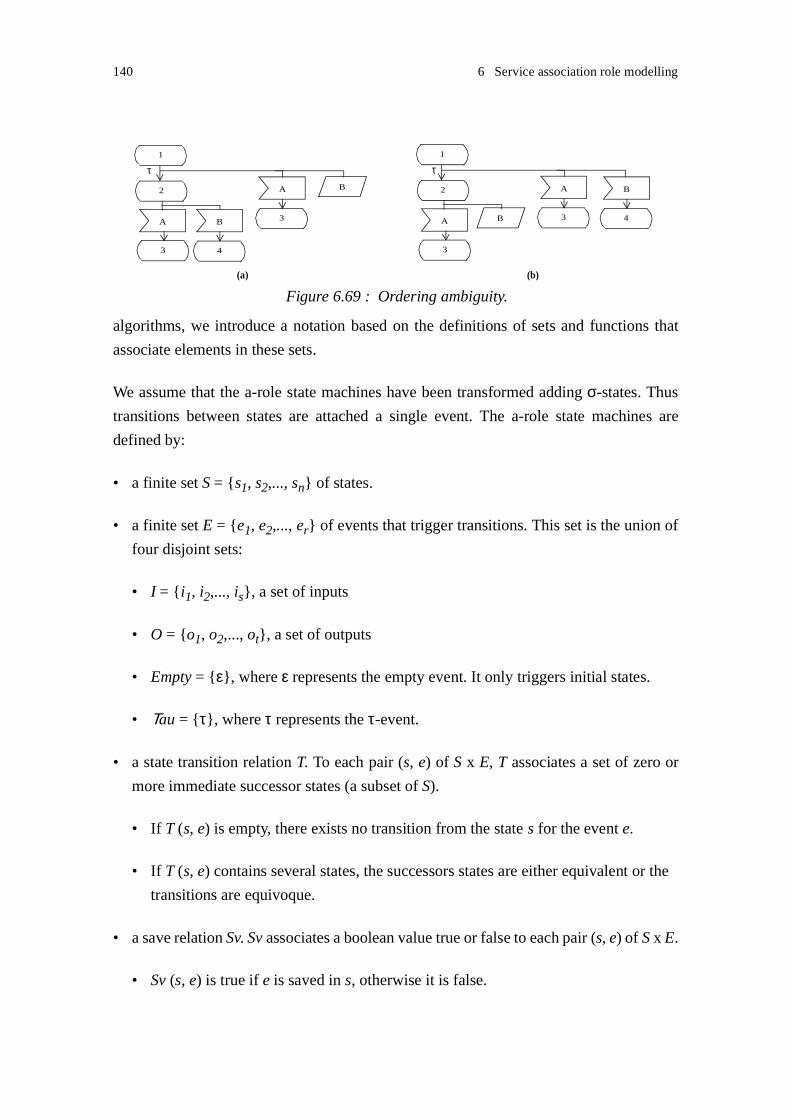
140 6 Service association role modelling
algorithms, we introduce a notation based on the definitions of sets and functions that
associate elements in these sets.
We assume that the a-role state machines have been transformed adding σ-states. Thus
transitions between states are attached a single event. The a-role state machines are
defined by:
• a finite set S = {s1, s2,..., sn} of states.
• a finite set E = {e1, e2,..., er} of events that trigger transitions. This set is the union of
four disjoint sets:
• I = {i1, i2,..., is}, a set of inputs
• O = {o1, o2,..., ot}, a set of outputs
• Empty = {ε}, where ε represents the empty event. It only triggers initial states.
• Τau = {τ}, where τ represents the τ-event.
• a state transition relation T. To each pair (s, e) of S x E, T associates a set of zero or
more immediate successor states (a subset of S).
• If T (s, e) is empty, there exists no transition from the state s for the event e.
• If T (s, e) contains several states, the successors states are either equivalent or the
transitions are equivoque.
• a save relation Sv. Sv associates a boolean value true or false to each pair (s, e) of S x E.
• Sv (s, e) is true if e is saved in s, otherwise it is false.
Figure 6.69 : Ordering ambiguity.
2
1
B
4
B
3
A 3
A 2
1
B 4
B
3
A 3
A
(a) (b)
τ τ

6.8 Set-based notation 141
• Sv (s, e) is false when T (s, e) is not empty.
In addition to these sets and relation, we define:
• a finite set Sσ = {σ1, σ2,..., σm} of σ-states. Sσ is a subset of S.
• a finite set So = {so1, so2,..., sol} of initial states. So is a subset of S. An entry condition
ci may be associated to state soi1.
• There exists no transition leading to an initial state.
• As we assume that the machine has been transformed adding σ-states, T (soi, e) is
empty for all events except the empty event ε.
• a finite set Se = {se1, se2,..., sen} of exit states. Se is a subset of S. An exit condition ci
may be associated to state sei.1
• Se can be derived from S, E and T. For all e in E, T (sei, e) is empty, since no transi-
tion from the state sei is defined.
• the relation enable. To each state s of S, enable associates the set of events that trigger
transitions from s. The event e belongs to enable (s) if and only if T (s, e) is not empty.
• the relation input-enable. To each state s of S, input-enable associates the set of input
events that trigger transitions from s. The event e belongs to input-enable (s) if and
only if e belongs to I and T (s, e) is not empty.
• the relation output-enable. To each state s of S, output-enable associates the set of out-
put events that trigger transitions from s. The event e belongs to output-enable (s) if
and only if e belongs to O and T (s, e) is not empty.
• the relation save. To each state s of S, save associates the set of events that may be
saved s. The event e belongs to save (s) if and only if Sv (s, e) is true.
1. Conditions attached to the s-roles are maintained during projection to a-roles. Conditions in SDL are expressed as labels.

142 6 Service association role modelling
We define the complement relations on the sets of states and events. These relations will
be relevant in Chapter 7 for the generation of complementary a-roles. The complement
relations are represented by an overline. They are defined such that:
• Each state s of S is associated a complement state s. S is the set of s.
• The complement relation does not maintain the save behaviour. The complement of
a σ-state is not a σ-state.
• The complement state of an initial state is an initial state, and we define soi = soi.
Thus So = So. If a condition is attached to an initial state, it is also attached to its
complement state.
• The complement state of an exit state is an exit state, and we define sei = sei. Thus
Se = Se. If a condition is attached to an exit state, it is also attached to its complement
state.
• Each event e of E, is associated a complement event e. E is the set of e.
• for each i of I, i is defined as the output of the same signal. I is the set of i.
• for each o of O, o is defined as the input of the same signal. O is the set of o.
• the complement event of ε is defined as ε = ε, and Empty = {ε}
• the complement event of τ is defined as τ = τ, and Τau = {τ}
• E is the union of I, O, Empty and Τau.
6.9 Minimisation algorithm
The aim of minimisation is to reduce the size of a state machine by replacing equivalent
states by a single state. Minimisation is usually applied before the analysis of large state
machines, for example when performing reachability analysis, or at design time when
requirements are set on the maximum size of machines, for example when developing
logical circuits. In our approach, as we first validate elementary a-roles, the size of state

6.9 Minimisation algorithm 143
machines we deal with is quite modest; obtaining size reduction is not absolutely neces-
sary. Minimisation is however of interest when applied together with gathering:
• It facilitates the identification of equivoque transitions. Equivoque transitions lead to
non-equivalent states. As minimisation removes the equivalent states, equivoque tran-
sitions are easily identified after minimisation: equivoque transitions are defined for
the same state and same event.
• It enables one to generate the canonical form of the specification of the consistent com-
plementary a-role. It should be applied to a-roles before the generation of consistent
complementary a-roles (see Section 7.1).
Recall that states are said to be equivalent when their τ-states define the same triggering
and save events, and their successor states are equivalent. By replacing equivalent states
by a single state, a state machine can be reduced to an equivalent state machine, i.e. a
machine that shows the same observable behaviour. The example in Figure 6.70, taken
from [Holzmann 1991], illustrates the minimisation of a state machine.
We propose a minimisation algorithm inspired by [Hennie 1968] and [Holzmann 1991].
Hennie’s algorithm is based on the notion of k-equivalence where states are k-equivalent
if they are not distinguishable by an experiment1 of length k. The algorithm generates par-
1. i.e. a sequence of observable events.
Figure 6.70 : Minimisation to an equivalent state machine.
1
A B
C
2 3
D
14
A B
C
5 6
D
41
1
A B
C
2 3
D
11
reduces to

144 6 Service association role modelling
titions of k-equivalent states; partitions are refined step-wise. Hennie’s algorithm only
applies to deterministic machines. Holzmann proposes a similar algorithm that makes use
of a state matrix instead of partitions, and that handles both deterministic and non-deter-
ministic machines. Our algorithm combines the partition approach and applies to
deterministic and non-deterministic machines.
As σ-states have a particular semantics, a σ-state can only be equivalent to a σ-state, not
to an ordinary state.
Algorithm 6.1: Minimisation
1. Generate τ-states
/* add a τ-transition from a state to itself */For each state p in Sset T(p,τ) = p
2. Build a partition P1 of 1-equivalent states
/* compare set of enabled and saved events */For all states p,q in Sif enable(p) = enable (q) and save (p) = save (q)if p is not an exit stateset p and q in the same block of partition P1elseif p and q define identical exit conditionsset p and q in the same block of partition P1
3. Build the partition Pk of k-equivalent states from Pk-1/* if the successors of (k-1)-equivalent statesin a block B of the partition Pk-1 are not equivalent,
split block B */
For each block B in Pk-1For all states p, q in BIf for each e in enable(p){for each s in T(p,e), ∃ s’ in T (q,e)such that s, s’ belong the same block of Pk-1andfor each s in T(q,e), ∃ s’ in T (p,e)such that s, s’ belong the same block of Pk-1}

6.9 Minimisation algorithm 145
set p and q in the same block of partition B
4. If (Pk-1 and Pk differ) and
some block in Pk contains more than one state
repeat step 3 with k=k+1
5. Define a reduced state machine by
- retaining a single state from each block in Pk.
If the state is an initial state, deduce anOR-condition from the conditions associatedto the states in the block. Attach this entrycondition to the state.If the state is an exit state, maintain thecondition of the state.
- redefining the transition T using the equivalent states.- remove any τ-transition from a state to itself.
When each state has only one successor after the occurrence of any event e (i.e. T(s, e) is
either empty or contains one state), the step 2 of the algorithm can be simplified as
described in Algorithm 6.2. In that case the machine does not contain any equivoque state,
and has a deterministic behaviour.
Algorithm 6.2: Minimisation (simplified - no potential equivoque transitions)
1. Generate τ-states: as step 1 in Algorithm 6.1
2. Build a partition P1: as step 2 in Algorithm 6.1
3. Build the partition Pk of k-equivalent states from Pk-1
For each block B in Pk-1For all states p, q in BIf for each e in enable(p)T(p,e) and T (q,e) belong the same block of Pk-1set p and q in the same block of partition B
4. Repeat: as step 4 in Algorithm 6.1
5. Define a reduced machine: as step 5 in Algorithm 6.1
When applying Algorithm 6.2 on the state machine described in Figure 6.42 on page 120,
we obtain the following partitions of 1-equivalent states: P1 = {(1,4), (2,5), (3,6)}. P1 is
then refined into a partition of 2-equivalent states P2. The block (1,4) of P1 is first consid-

146 6 Service association role modelling
ered. The successors of state 1 by event A and B are respectively 2 and 3. The successors
of state 4 by event A and B are respectively 5 and 6. As the states 2, 5 and 3, 6 belong the
same blocks in the partition of P1, the block (1,4) remains unchanged in P2. By reasoning
similarly on blocks (2,5) and (3,6), the partition P2 is found to be identical to P1. Thus step
2 of the algorithm need not to be repeated. A reduced machine is defined that contains the
states 1, 2, 3.
6.10 Summary
In this chapter, we have defined a projection from s-roles to a-roles. The projection
abstracts non-observable behaviours of s-roles. Internal actions and non-visible signals
are hidden. The consumption of non-visible signals is transformed to spontaneous transi-
tions. A notation inspired from SDL is proposed for modelling a-roles. A set-based
notation is also defined; this notation will be used in the definition of validation algo-
rithms in Chapter 7.
The proposed projection assumes that:
• All communication between s-roles take place by the exchange of signals, and that sig-
nals exchanged on an association between two s-roles are conveyed on the same
communication path.
• The s-role state graph has been transformed in order to remove enabling conditions.
This is possible as communication between s-roles is restricted to signal exchange.
• The valid association input signal sets and valid association output signal sets related
to distinct s-role associations are disjoint.
The projection maintains the observable association behaviour provided that:
• S-roles are designed according to the design rule "Save consistency". This means that
the saving of a signal should be re-iterated in the successor state(s) of the state where
save can occur until the consumption of the saved signal is specified.
• S-roles are designed according to the design rule "Ordering with save and concur-
rency". This means that using save in the modelling of alternative signal orderings
should not overlap with the modelling of concurrent behaviours.

6.10 Summary 147
The a-role state graph obtained by projection can be transformed in order to facilitate
interface validation. The chapter has proposed three transformations:
• A-role state graphs are transformed to transition charts. A transition chart is a kind of
state graph where transitions between states are attached a single event: an input, an
output or a silent event (τ-event). The transformation is performed through the inser-
tion of σ-states.
• State gathering is applied in order to remove non observable τ-transitions. We define
two transformations: strong gathering and weak gathering. Weak gathering only main-
tains the observable behaviour provided that spontaneous transitions can occur. Strong
gathering always maintains the observable behaviour.
• Minimisation is applied in order to replace equivalent states by a single state. A mini-
misation algorithm based on the classification of states into equivalence partitions is
defined.
In the following, we will assume that these transformations have been applied to the a-
role transition charts.
Finally, we have also identified particular anomalous specification patterns:
• Equivoque transitions and acute τ-transitions may lead to ambiguous behaviours.
• Mixed initiative states may lead to conflicting behaviours.
Ambiguous and conflicting behaviours are usually symptoms of errors, and will require
special care during interface validation. Ambiguous and conflicting behaviours are prop-
erties of state machine types - not instances. They can be identified at system design.

148 6 Service association role modelling

- 149 -
7
Interface validation
The purpose of interface validation is to ensure that the interfaces, i.e. service association
roles (a-roles), on associations between service roles (s-roles) interact consistently. This
chapter discusses the validation of interactions between elementary s-roles. The valida-
tion of interactions between composite s-roles is presented in Chapter 8.
Depending on the specification approach, a-roles may be specified before s-roles are
themselves defined, or they may be obtained by projections of s-roles on an association.
In other words, a-roles may either be seen as the desirable behaviour of an s-role on an
association, or the actual behaviour of an s-role on an association. Similarly, interface val-
idation can be used as a method for producing desirable behaviours or checking actual
behaviours. Applied as a constructive method, interface validation aims to generate a dual
consistent a-role from a particular a-role. Applied as a corrective method, interface vali-
dation aims to check the consistency of two a-roles.
This chapter describes first the constructive method. When discussing the generation of
dual a-roles, we propose solutions to handle ambiguous and conflicting behaviours. The
discussion results in a set of design rules that support the development of well-formed
machines. These rules are also essential in the corrective method. Rather than directly
checking the consistency of two a-roles, we identify first whether or not the a-roles
present the right properties for interacting consistently with other a-roles. Thus we can
avoid to apply consistency checking on poorly designed s-roles and a-roles.
A main advantage of the approach is that the techniques that are proposed, can be easily
understood. Simplicity is however achieved at the sacrifice of some shortages. They are
discussed in Section 7.3.
The assumptions and design rules introduced in Chapter 6 apply. The signals exchanged
between a-roles are conveyed on the same communication path, and thus signal ordering

150 7 Interface validation
is preserved during transport. A-roles are described by transition charts, and equivalent
states have been reduced by minimisation.
7.1 Dual service association role
In this section, we discuss the problem of specifying an a-role that interacts consistently
with a given a-role. Intuitively, we tend to believe that a consistent a-role can be produced
by mirroring, where mirroring is a transformation that maintains the structure of the
graph, and transforms inputs to outputs and outputs to inputs. We will show that mirroring
fails to work when equivoque transitions or acute τ-transitions are introduced. Mixed ini-
tiatives states also require special care.
In our discussion, we consider the whole behaviour of the initial a-role state machine, not
only parts of it. We aim to specify complementary a-roles that, through interaction with
the initial a-roles, provide the full behaviour expected by the initial a-roles. We assume
that any state in the initial a-role machine is reachable from an initial state through some
sequence of events. With that assumption, we know that any anomalous behaviour speci-
fied in the machine can be reached and execute.
Definition: Dual service association role
A dual a-role is a complementary a-role of a given a-role, that interacts consistently1 with
this given a-role. The full behaviour of the a-role can be covered through interaction
between the a-role and the dual a-role.
Recall that the consumption of signals from other associations, are projected to spontane-
ous transitions in the a-role. Spontaneous transitions may occur at any time. As our aim
is not identify deadlocks2 that may occur following errors of the non-visible behaviour of
an s-role, e.g. errors on other associations, we assume that any spontaneous sending
described by the a-roles can occur. With this assumption, we are able to check that a-roles
interact consistently when they provide the expected behaviour.
7.1.1 Mirroring
Definition: Mirroring
Mirroring is a transformation on a state graph that produces a complement state graph: the
structure of the graph is maintained, inputs are transformed to outputs, outputs to inputs,
1. Interaction consistency has been defined in Section 5.52. A deadlock may occur when none of the spontaneous sending described in a state ever occurs.

7.1 Dual service association role 151
and empty events and τ-events remain respectively empty events and τ-events. Save is not
maintained by mirroring. Conditions associated with initial and exit states are associated
with the complement states.
Observe that:
• As save is not maintained by mirroring, σ-states are mirrored to normal states.
• As the graph structure is maintained, exit nodes are transformed to exit nodes, and
cycles are preserved.
Figure 7.1 illustrates the mirroring of a state graph. Notice that without the insertion of an
σ-state, the signal sending in the initial state would be transformed to a signal consump-
tion in an initial state; this is not allowed in SDL. The insertion of σ-states facilitates the
mirroring transformation.
Algorithm 7.1 defines a mirroring algorithm in a pseudo-code form. The state graph is
transformed in depth-first manner starting from each initial state (a graph may contain
several initial states). The algorithm may apply to any state graph showing deterministic
or non-deterministic behaviour. It makes use of the notation introduced in Section 6.8.
Algorithm 7.1: Mirroring
main (){/* define graph elements: states and events */S = S; /* maintain any associated condition */
Figure 7.1 : Mirroring a state machine.
B C
D
2 3
E
11
mirrors to
D E
B
2 3
C
11
1
A A
0
1
σ−0

152 7 Interface validation
I = I; O = O;/* set of mirrored states, initialise to empty */M = {};
/* start from all initial states */for each so in Soif so is not in M
mirror (so);
}
mirror (s) /* mirror the transition relation */{add s to M;
if s is a σ-stategenerate new state name s
for each e in E
define T(s, e) = T (s, e);
for each successor n of sif n is not in Mmirror (n);
}
7.1.1.1 Mirroring simple machines: no equivoque transitions, no mixed initiative
V-rule: Mirroring and duality
The dual a-role of an a-role that
- does not contain any equivoque transitions, and
- does not contain any acute τ-transition, and
- does not contain any mixed initiative state,
can be obtained by mirroring.
The initial a-role and the a-role obtained by mirroring interact consistently provided that
- they both start execution consistently, i.e. the machines should be entered using consist-
ent entry conditions, and
- any spontaneous sending can occur.
Notice that, as we assume that machines are minimized before applying mirroring, the ini-
tial states, if several exist, are not equivalent, and thus are associated different entry
conditions.

7.1 Dual service association role 153
In the example shown in Figure 7.1, the a-role obtained by mirroring is a dual a-role of
the initial a-role. This can easily be checked by considering all possible behaviours.
Justification:
We first prove that each state is mirrored to a consistent state (i.e. a state it interacts con-
sistently with):
- As a state is mirrored to a complement state that is enabled by complement events and
no other events: a state can consume any event sent its complement state, and any event
sent by a state can be consumed by its complement state. The full behaviour of each state
is covered.
- Following the assumption that any spontaneous sending can occur, at least one of the
output event described by a state that only describes spontaneous event sendings, occurs.
No deadlock following that the machine never sends in such state occurs.
- As states are not mixed initiative states, their mirrored states are not mixed initiative
states. Only one of the machines initiates a new transition; as any trigger is specified as
input in the complement state, unspecified signal reception does not happen. Only one
machine waits for an event sent by the other; thus deadlock following machines waiting
for each other is also avoided.
- An exit node is mirrored to an exit node and exit conditions are maintained. Thus,
improper termination is avoided.
Now that we have proved that states and their mirrored states are consistent, we prove that
transitions and their complement transitions preserve consistency:
- As transitions are not equivoque, each state have a unique successor succ for each event.
The successor state of a complement state triggered by the complement event, i.e. T(s, e),
is defined in mirroring as T (s, e). It is the complement state of the successor state succ,
and thus is consistent with the successor succ. Each transition is transformed, and each
successor state can be reached providing full behaviour.
- As the graph does not contain any equivoque transitions, an empty transition in an initial
state leads to a single state. Such empty transition is mirrored to an empty transition. They
lead to states that interact in a consistent manner.
- As the graph, and thus the mirrored graph, does not contain any acute τ-transition, the
transitions occur in a coordinated manner: a transition in one graph is triggered by a tran-
sition in the complement graph, and conversely.
Finally, as we have proved that states and their mirrored states are consistent, and that
transitions and their complement transitions preserve consistency, we prove that execu-
tion is started consistently:
- Mirroring maintains entry conditions, i.e. a mirrored state is attached the same entry con-

154 7 Interface validation
dition as the initial state.
- The initial machine and the mirrored machine are entered using consistent entry condi-
tions. In the same manner as any transition, initial transitions preserve consistency and
lead to consistent states.
From this justification, we can also deduce that the full behaviour of the dual a-role can
be covered through interaction between the a-role and the dual a-role.
7.1.1.2 Event ordering and save
The information about signal saving is not maintained in the mirrored graph. This is not
needed, as mirroring preserves the structure of the state graph, and thus the ordering of
event sequences. Mirroring enforces a strict ordering on the dual a-role. As explained in
Section 6.4 on page 124, it may be desirable to relax the ordering requirements. This is
possible if the list of events that may be saved in the initial state is attached to the mirrored
state. In that case, events may be re-ordered. Information about σ-states can also be
attached to the mirrored states. The design rule "Save consistency" facilitates the re-order-
ing operation: we know that any save signal can be consumed after saving.
Figure 7.2 illustrates the pertinence of save information. In case (a), the dual role is
obtained by mirroring, and events are strictly ordered. If information about the saving of
“C” in state “2” is made available in the mirrored role, the sequence of events in the dual
role can be re-ordered. This is shown in case (b). As “B” may be sent at any time, the sig-
nal “B” should be saved in state “2a”. In the new dual role, the sending of “C” may be
done at once without waiting for “B”.
Figure 7.2 : Mirroring and event re-ordering.
A
1
B
2
3
C
1
mirrors toB
1
A
2
3
(a) dual a-role
1
C B
1
A
2a
3a
(b) alternative dual role
1
CC Bre-orders
saved: C

7.1 Dual service association role 155
In the rule "Save and ordering", we have advised that the use of save for modelling alter-
native ordering should be restricted to special cases. The detailed description of re-
ordering is left for further work.
7.1.2 Equivoque transitions
In this section, complexity is added to the a-role graphs by introducing equivoque transi-
tions. We show that it is not possible to define dual a-roles for a-roles that contain strong
input ambiguity or strong mixed ambiguity. Mirroring also fails to produce dual a-roles
when applied directly to a-roles that contain equivoque transitions, even if they do not
present any strong behaviour ambiguity. The machine should be transformed before mir-
roring. We first define a set of transformation and validation rules that apply to machines
containing equivoque transitions. Then we introduce algorithms for the manipulation of
such machines.
As an illustration of the problem, Figure 7.3 presents a state machine containing equiv-
oque transitions. In this example, the equivoque transitions do not lead to any input or
mixed ambiguity. An external observer is able to perceive which behaviour is selected
when receiving “C” or “D”. However, the state machine obtained by mirroring presents
an input ambiguity. The initial machine cannot, after the consumption of “B”, determine
whether the mirrored machine is waiting for “C” or “D”, and thus whether “C” or “D”
should be sent.
Figure 7.3 : Mirroring and equivoque transitions.
1
B
A
4
2 3
5
divergence ofbehaviour,
A
B
C D
1
A
B
4
2 3
5
B
A
C D
mirrors to
input ambiguityno ambiguity

156 7 Interface validation
7.1.2.1 Basic rules
T-rule: Mirroring and equivoque transitions
The a-role obtained by mirroring an a-role that contains equivoque transitions, contains
equivoque transitions. Equivoque transitions are mirrored to equivoque transitions.
Justification:
This is obvious. As mirroring maintains the structure of graph, i.e. both states and transi-
tions, distinct behaviour sequences occurring after equivoque transitions are mirrored to
distinct behaviour sequences.
This straightforward rule will be needed in the justification of some of the next rules.
T-rule: Mirroring and equivoque transitions, but no ambiguity
The a-role obtained by mirroring an a-role that contains equivoque transitions, but does
not present any strong or weak input ambiguity, any strong or weak mixed ambiguity, any
termination ambiguity, nor exit condition ambiguity always presents an input ambiguity.
Justification:
We know that equivoque transitions are mirrored to equivoque transitions. The equivoque
transitions lead to distinct behaviour. As the initial machine does not present any ambigu-
ity, the initial divergent behaviour necessarily occurs as signal sending. These outputs are
transformed to inputs by mirroring, and thus the complementary behaviour of the initial
divergent behaviour occurs by signal consumption. This means that the mirrored machine
presents an input ambiguity.
V-rule: Duality and strong input ambiguity
Provided that strong input ambiguity is not withdrawn by save1, it is not possible to spec-
ify a dual a-role for an a-role that presents an input ambiguity.
Justification:
There exists some stage of the interaction where an external observer knows that the a-
role state machine expects only input(s), but is not able to determine which input(s) is
(are) expected. Since strong input ambiguity is not withdrawn by save, the machine does
not save any of the expected input. At that stage, sending a signal may lead to an unspec-
ified signal reception. Thus it is not possible to specify a complementary a-role that
interacts consistently with the initial a-role.
1. See Section 6.5.1.1.

7.1 Dual service association role 157
T-rule: Mirroring and duality: equivoque transitions, no ambiguity
The a-role obtained by mirroring an a-role that contains equivoque transitions, but does
not present any ambiguity, is not a dual a-role of that a-role.
Justification:
We know that the a-role obtained by mirroring presents an input ambiguity. At some stage
of the interaction, the a-role does not know which input(s) is (are) expected by the mir-
rored a-role. Thus sending a signal may lead to an unspecified signal reception. The two
a-roles do not interact consistently.
V-rule: Duality and strong mixed ambiguity
Provided that strong input ambiguity is not withdrawn by save1 on Page 156, it is not possi-
ble to specify a dual a-role for an a-role that presents a mixed ambiguity.
Justification:
There exists some stage of the interaction where an external observer knows that both
input(s) and output (s) may occur, but is not able to determine any of the input or output
events expected by the a-role state machine. Since strong input ambiguity is not with-
drawn by save, the machine does not save any of the expected input. At that stage, sending
a signal may lead to an unspecified signal reception, and waiting for a signal to a deadlock.
Thus it is not possible to specify a complementary a-role that interacts consistently with
the initial a-role.
V-rule: Duality and termination ambiguity
It is not possible to specify a dual a-role for an a-role that presents a termination
ambiguity.
Justification:
As termination ambiguity is either a special case of input ambiguity or mixed ambiguity,
the rule can be deduced from the validation rules related to input and mixed ambiguities.
T-rule: Mirroring and duality: weak input ambiguity
Provided that weak input ambiguity is not withdrawn by save, the a-role obtained by mir-
roring an a-role that presents a weak input ambiguity, is not a dual a-role of that a-role.
Justification:
There exists some stage of the interaction where the a-role state machine expects only
input(s), but the set of expected inputs vary. The machine may enter different states in a

158 7 Interface validation
non-deterministic manner. Mirroring transforms any input expected at that stage to an out-
put in the mirrored machine. Non-determinism is preserved by mirroring, meaning that
the mirrored machine may enter a state where it sends an event that is not expected by the
initial machine. This is an unspecified signal reception. Thus the mirrored a-role is not a
dual a-role of the initial a-role.
In order to facilitate the understanding of that rule, an example is shown in Figure 7.4. The
initial and mirrored machines enter state “2” or “3” in a non-deterministic manner. If the
mirrored machine enters state “3” and sends signal “C” while the initial machine enters
state “2”, an unspecified signal reception occurs.
T-rule: Mirroring and duality: weak mixed ambiguity
Provided that weak mixed ambiguity is not withdrawn by save, the a-role obtained by mir-
roring an a-role that presents a weak mixed ambiguity, is not a dual a-role of that a-role.
Justification:
The justification is similar to that of the previous rule. There exists some stage of the inter-
action where the both input and output events may happen, but the set of expected events
vary. Both machines may enter different states in a non-deterministic manner, and one of
the machine may send an event that is not expected by the complementary machine. Thus
the mirrored a-role is not a dual a-role of the initial a-role.
In order to facilitate the understanding of that rule, an example is shown in Figure 7.5. The
initial and mirrored machines enter state “2” or “3” in a non-deterministic manner. If the
initial machine enters state “3” and sends signal “C” while the mirrored machine enters
state “2”, an unspecified signal reception occurs. Notice that the input overlap in the initial
machine is transformed to an output overlap in the mirrored machine.
Figure 7.4 : Mirroring and weak input ambiguity.
A
2
1
B
3
B C
4 5 6
mirrors to
B
2
1
3
4 5 6
A
B C

7.1 Dual service association role 159
7.1.2.2 Identifying equivoque transitions and divergent behaviour
As a-roles containing equivoque transitions cannot be mirrored to dual a-roles, it is essen-
tial to be able to detect equivoque transitions. We propose algorithms for marking the
states where equivoque transitions happen, and categorising the divergence of behaviour
they lead to. The categorisation is important as we know that it is not possible to produce
a dual a-role of an a-role presenting a strong input, strong mixed or termination ambiguity.
In the case such ambiguity is found, the designer should re-specify the a-role. Design rules
for removing ambiguity are presented in Section 7.1.2.5.
A divergence of behaviour does not necessarily occur in the states immediately following
equivoque transitions. The identification of divergent behaviour requires traversing the
state graph. Figure 7.6 describes a case where several and different kinds of behaviour
divergency occur after equivoque transitions.
Figure 7.5 : Mirroring and weak mixed ambiguity.
A
2
1
B
3
C B B
2
1
A
3
BC
mirrors to
Figure 7.6 : Divergent behaviour occurring after identical signal sequences.
1
A
C
4
D
2
identical behaviour
equivoque transitions
B
3
E
5
F
G
6
H
7
A
C
9
I
8
B
3
E
10
F
J
11
input ambiguity
observable divergence
input ambiguity

160 7 Interface validation
Algorithm 7.2 supports the identification of states that define equivoque transitions. The
state graph is analysed in depth-first manner starting from each initial state. We assume
that the graph has been minimized and does not contain any equivalent states. The algo-
rithm makes use of the notation introduced in Section 6.8.
Algorithm 7.2: Identifying equivoque transitions
main (){/* Assumption:
- the graph has been minimized - no equivalent states*/EQ = {}; /* set of equivoque states */W = {}; /* working set *//* start from all initial states */for each so in Soif so is not in W
identify-equivoque(so);
}
identify-equivoque (s){add s to W;for each e in enable (s)if T (s, e) contains more than one element add s to EQ;for each successor n of s /* element of T (s, e) */if n is not in Widentify-equivoque (n);
}
Algorithm 7.3 supports the characterisation of divergence of behaviour occurring after
equivoque transitions. Equivoque transitions should first be identified using
Algorithm 7.2. The divergence of behaviour is either classified as output divergence,
strong or weak input ambiguity, strong or weak mixed ambiguity, termination ambiguity,
or exit condition ambiguity. When a divergence of behaviour is identified, the states
where it occurs, are stored together with the state where the equivoque transitions occur.
The state graph is analysed in a depth-first manner starting from each state where equiv-
oque transitions occur:
• The algorithm first identifies which kind of divergence occurs in the states triggered by
the equivoque transitions. In the case of input or mixed ambiguity, the divergence is
classified as “weak” if the successor states describe some behaviour overlap.

7.1 Dual service association role 161
• The analysis is repeated step-wise, when distinct successor states can be reached by
identical behaviour sequences after the occurrence of equivoque transitions.
The algorithm fails to identify when distinct sets of equivoque transitions lead to the same
states. In order to avoid non-progress cycles in the algorithm, the analysis of states that
have already been analysed is not repeated. This means that a divergence of behaviour is
related to a single set of equivoque transitions, while it may also occur after some other
set of equivoque transitions.
The algorithm does not take into account save signals attached to states, and does not iden-
tify when input or mixed ambiguities are withdrawn by save (see Section 6.5.1.1 and
Section 6.5.2.1). This means that some behaviours may be classified as ambiguous while
they in fact are not.
Algorithm 7.3: Classifying the divergence of behaviour after equivoque transitions
main (){/* Assumption:
- equivoque states are stored in EQ (Algorithm 7.2)*/Ieq = EQ; /* initial set of equivoque states*/
W = {}; /* working set - contains analysed state tuples */
/* The following sets contain elements of the form:(eq, div) where
eq is an equivoque state,div a state tuple (si, sj,...) where behaviour
diverges*/D-out = {}; /* output divergence */D-in-s = {}; /* strong input ambiguity */D-in-w = {}; /* weak input ambiguity */D-mix-s = {}; /* strong mixed ambiguity */D-mix-w = {}; /* weak mixed ambiguity */D-term = {}; /* termination ambiguity */D-term-cond = {}; /* exit condition ambiguity */
/* start from all equivoque states */for each eq in Ieqremove eq from Ieqfor each a in enable (eq)if T (eq, a) contains more than one element

162 7 Interface validation
if T (eq, a) is not in Widentify-divergence (eq, T(eq, a));
}
identify-divergence (s-eq, SUCC){add SUCC to W;
Events = {}; /* events in successor states */for each p in SUCCadd enable(p) to Events;
if Events is empty /* successors are exit states */add (s-eq, SUCC) to D-term-cond; /* exit cond. ambig. */return;
Common-Events = {}; /* common events in successor states */for one p in SUCCset Common-Events to enable(p);for each p in SUCC /* find intersection of event sets */set Common-Events to Common-Events ⊕ enable(p);
/* identify divergence */if for some e in Events,e is not in enable(p) for some p in SUCC /* divergence */{if T(q, e) is element of Se for some q in SUCC /* exit */
if T(r, e) is not element of Se for some r in SUCC
add (s-eq, SUCC) to D-term; /* termination ambig. */
if Events is included in O /* output divergence */add (s-eq, SUCC) to D-out;
else if Events is included in I /* input ambiguity */if Common-Events is emptyadd (s-eq, SUCC) to D-out-s; /* strong */elseadd (s-eq, SUCC) to D-out-w; /* weak */
else /* mixed ambiguity */if Common-Events is emptyadd (s-eq, SUCC) to D-mixed-s; /* strong */
elseadd (s-eq, SUCC) to D-mixed-w; /* weak */
}

7.1 Dual service association role 163
/* identify partially common behaviour and analyse it */
for each e in Eventss-num = 0; /* number of successor states */S-SUCC = {}; /* set of successor states */for each p in SUCC if e is in enable(p)add T(p, e) to S-SUCC;s-num = s-num + 1;n-eq = p;
if S-SUCC contains more than one elementif S-SUCC is not in Wif s-num is equal to 1 /* equivoque transitions */remove n-eq from Ieqidentify-divergence (n-eq, S-SUCC);
elseidentify-divergence (s-eq, S-SUCC);
}
7.1.2.3 Equivoque transitions with no ambiguity
Given an a-role that contains equivoque transitions, but does not present any ambiguity,
we have shown that a dual a-role cannot be obtained by mirroring. However, it is possible
to specify a dual a-role for such an a-role. We will show that a simple transformation that
merges the behaviour occurring after the equivoque transitions should be applied before
mirroring.
Figure 7.7 illustrates this transformation. Mirroring failed to generate a dual a-role for the
initial machine (see Figure 7.3). However, the machine obtained after “merging” and mir-
roring, as described in case (c) on Figure 7.7, is a dual a-role of the initial machine. This
can be easily checked by considering all possible behaviours. The initial machine was first
transformed to an intermediary machine by merging the states exhibiting the non-distin-
guishable behaviours and occurring after the equivoque transitions. The transformation
removes ambiguity, and enables to produce, by mirroring, a machine that presents no
ambiguity. Notice that the initial machine does not need to be modified: the equivoque
transitions are not removed. As the initial machine controls the interaction when the diver-
gence of behaviour occurs (i.e. the machine sends a signal), it is possible to specify a dual
machine.

164 7 Interface validation
7.1.2.3.1 Merging
Definition: Merging
Merging is a transformation that applies distinct states reachable from a state triggered by
equivoque transitions through the same sequence of events. Merging produces a new state
that exhibits the behaviour of the merged states (i.e. can be triggered by all events that can
trigger any of the merged states). The transitions from the state triggered by equivoque
transitions to the states being merged are replaced by a transition to the merged state.
Merging does not apply to exit states.
Merging will mainly be applied on state machines that do not present any input, mixed or
termination ambiguity. However as discussed in Section 7.1.2.5, merging is also of inter-
est when re-designing an a-role that presents input or mixed ambiguity. Merging is never
applied on machines that present a termination ambiguity, this because exit states have a
particular semantics (the machine stops), and should not be merged with non-exit states.
The merging transformation may be extended in order to handle the merging of distinct
exit states. This is actual when a state machine presents an exit condition ambiguity. This
is further explained in Section 7.1.2.4
A state machine may present several ambiguities after the occurrence of equivoque tran-
sitions. Every branch in the graph that succeeds a set of equivoque transitions is merged.
Figure 7.8 illustrates the merging transformation on a slightly more complex example
than in Figure 7.7. First, the states following the equivoque transitions are merged: states
Figure 7.7 : Equivoque transitions: merging behaviour before mirroring.
1
B
A
4
2 3
5
divergence ofbehaviour
A
B
C D
1
A
B
4-5
2-3
C D
mirrors to
1
B
A
4-5
2-3
C D
merges to
(b) intermediary machine(a) initial machine (d) dual machine

7.1 Dual service association role 165
“2” and “9” are merged to state “2-9”. The new state can be triggered by the events of state
“2”, i.e. “B”, “C” and “G”, and the events of state “9”, i.e. “B” and “C”. The transitions
triggered by “B” and “G” lead to single states; they remain unchanged. The transitions
triggered by “C” lead to distinct states “4” and “10”. The states “4” and “10” can be
reached by the same sequence of events from state “1”, i.e. “A” and “C”; they are merged
to state “4-10”. The new state is triggered by a single event D. The merging continues until
no more distinct states need to be merged.
T-rule: Merging and equivoque transitions
An a-role that contains equivoque transitions and does not present any termination ambi-
guity is transformed by merging to an a-role that does not contain any equivoque
transitions.
Justification:
By definition of merging, states reachable from a state triggered by equivoque transitions
are merged to a single state. Thus equivoque transitions are merged to a single transition.
Algorithm 7.4 defines a merging algorithm in a pseudo-code form. We assume that the
machine does not present any termination ambiguity or exit condition ambiguity (merging
is never applied on exit states). We also assume that the machine does not contain any
equivalent states. The state graph is transformed step-wise in depth-first manner starting
Figure 7.8 : Merging.
1
A
G
8
2
B
3
C
5
6 7
D
4
FE
A
9
B
3
C
11
12
D
10
E
1
A
G
8
2-9
B
3
C
5-11
6-12 7
D
4-10
FE
merges to

166 7 Interface validation
from each state where equivoque transitions occur. Distinct states that are reachable from
that state through the same sequence of events are merged to a new state; this state is
defined with the transitions of the merged states. The merging is repeated for the distinct
successor states triggered by the same event.
Algorithm 7.4: Merging
main (){/* Assumptions:
- no equivalent states- no termination ambiguity
*//* Equivoque states are stored in EQ (Algorithm 7.2) */
W = {}; /* working set - contains merged state tuples */
/* merged-state is a relation that keeps track ofthe association between a tuple of merged statesand their merged state */
/* start from an equivoque state */for each s in EQ
remove s from EQfor each e in enable(s)if T (s, e) contains more than one elementmerge (s, e);
}
merge (s, e){if every p of T(s, e) is element of Se /* any exit */
report-error (exit condition ambiguity);return;
if some p of T(s, e) is element of Se /* one exit */
report-error (termination ambiguity);return;
if T(s, e) is not in W{add T(s, e) to W;
create new state n; /* add n to S */set merged-state(T(s, e)) to n;SUCC = T(s, e);

7.1 Dual service association role 167
T(s, e) = n; /* redefine transition */
for each a in E, set T(n, a) = {}; /* initialisation */for each q in SUCCfor each a in enable(q)add T(q, a) to T(n, a)add a to enable(n);
for each a in enable(n)if T(n, a) contains more than one elementmerge (n, a)
}else /* the merged state already exists */T(s, e) = merged-state(T(s, e));}
The merging algorithm does not remove any state from the graph. Some of the merged
states may, after merging, no longer be reachable from the initial states. These states can
be easily removed by applying Algorithm 7.5. The merging transformation may also
introduce new equivalent states. Equivalent states should be replaced by a single state by
minimisation (Algorithm 6.2). When these two transformations have been performed, the
mirroring transformation can be applied.
Algorithm 7.5: Removing non-reachable states
main (){W = {}; /* working set - reachable states */
/* start from all initial states */for each so in Soif so is not in W
mark-successor (so);
set S to W;}
mark-successor (s){add s to W;
for each successor n of sif n is not in Wmark-successor (n);
}

168 7 Interface validation
7.1.2.3.2 Merging and save
The proposed definition of merging ignores the saving of signals. As a consequence, an
a-role is transformed by merging to an a-role that may provide a modified observable
association behaviour.
Two case examples are shown in Figure 7.9. In the case (a), the states to be merged define
identical sets of saved signals. The design rule "Save consistency" is enforced by consum-
ing the signal in the successor state “3”. An external observer may send “D” immediately
after “A”. When it receives “B” or “C”, the machine proceeds. After merging, the same
behaviour may lead to the discarding of “D” and a deadlock. In case (b), the states to be
merged define distinct sets of saved signals. This case illustrates a kind of save ambiguity:
an external observer cannot determine from any observable event that the signal “D” can
be saved. Also in that case, an external observer perceives distinct behaviours before and
after merging. When sending “D” immediately after “A”, the a-role before merging
always proceeds after “B” is received. After merging, it sometimes deadlocks.
We may redefine the merging transformation so that the save set of a state obtained by
merging, is defined as the intersection of the save sets of the states being merged. For
example, state “X” merged from case (a) of Figure 7.9 would define the save set “D”. In
the case where the state being merged defined distinct save sets, the new merging trans-
formation does not maintain the observable association behaviour. For example, state “X”
merged from case (b) in Figure 7.9 would not define any save set as when using the initial
merging transformation. Algorithm 7.4 is easily extended so that a save set is computed
and attached to the merged state.
Figure 7.9 : Merging and save.
2
C
3
B
3
4
C
3
B
3
X
merges to
(a) identical save sets
1
A
1
A
D D
2
C
3
B
3
4
1
A
D
merges to
(b) distinct save sets
D D D

7.1 Dual service association role 169
The merging of two or more σ-states is a particular case and should lead to a σ-state.
Recall that the semantics of σ-states is also different from other states, in that one of the
output events described in σ-state always occurs.
We intend to apply merging before mirroring. Merging and mirroring should be defined
consistently. When the information about signal saving is not maintained in the mirrored
graph, maintaining save during merging is not needed. Both merging and mirroring
enforces a strict ordering on the dual a-role. Otherwise, when mirroring maintains the save
information1, merging should maintain save.
V-rule: Merging and save ambiguity
Assume an a-role containing equivoque transitions, but no input, mixed, termination or
exit condition ambiguity. If some of the states being merged define distinct save sets, the
a-role presents a save ambiguity.
Justification:
As the a-role does not present any input, mixed, termination or exit condition ambiguity,
the divergence of behaviour occurring after the equivoque transitions is perceived through
output events. The states between the state triggered by the equivoque transitions and the
states triggered by these output events are merged. An external observer cannot distin-
guish between the states being merged. If some of these states define distinct save sets, an
external observer cannot determine which signals can be saved, except the common sig-
nals in the save sets.
When an a-role presents a save ambiguity, a complementary a-role cannot take advantage
of save, except for the common signals in the save sets. Therefore it is acceptable that
merging ignores signals that are not common to the save sets.
D-rule: Merging and save ambiguity
We advice to redefine a-roles2 presenting save ambiguities such that save sets of states
being merged define identical save sets.
T-rule: Merging and σ-state
The merging of a σ-state with a non σ-state may modify the observable association behav-
iour provided by an a-role.
1. as described in Section 7.1.1.2.2. When a-roles are derived from s-roles, the s-roles need to be redefined.

170 7 Interface validation
Justification:
The state obtained by merging is not a σ-state and then behaves differently from the initial
σ-state. An example is shown in Figure 7.10. When interacting with the initial role, an
external observer that sends “D” immediately after “A” observes that the a-role always
proceeds after “C” is received. When interacting with the a-role obtained by merging, an
external observer that sends “D” immediately after “A” observes that, in some cases, the
a-role deadlocks after “C” is received.
In that case, redesigning the a-role is more complex. We rather propose to enforce a strong
ordering on the complementary a-role.
Definition: Merging with save
“Merging with save” extends the merging transformation:
- The save set of a state obtained by merging, is defined as the intersection of the save sets
of the states being merged.
- σ-states are merged to a σ-state.
T-rule: “Merging with save” and observable behaviour
An a-role that contains equivoque transitions, but that
- does not present any input, mixed, termination or exit condition ambiguity,
- and does not contain any acute τ-transitions,
is transformed by “merging with save” to an a-role that exhibits the same behaviour pro-
vided that the states being merged define identical save sets, and that σ-states are only
merged with other σ-states.
Figure 7.10 : Merging and σ-state.
2
C
3
B
3
σ−0
projects/
C
3
B
3
Xmerges to
s-role
initial a-role a-role after merging
2
1
X3
B
C
transforms
3
1
A
1
A
A
D

7.1 Dual service association role 171
Justification:
States being merged are distinct states that are reachable from a state triggered by equiv-
oque transitions through the same sequence of events. We have to show that a merged
state and its successor states behave as the states being merged and their successors. The
states should be triggered by the same events, and signals should be stored and retrieved
in/from the input port in the same manner.
As the a-role does not present any input, mixed, termination or exit condition ambiguity,
the divergence of behaviour only occurs through output events. The states being merged
either define the same set of events, or they define different output events.
- If the states being merged define the same events, the merged state also defines this set
of events. Thus, the merged state is triggered in the same manner as the initial states. For
each event, the successor state(s) of the initial states is (are) either identical or differ. In
the first case, triggering obviously leads to the same behaviour. In the second case, the
successor states are merged. By applying the reasoning recursively, the successor states
can be shown to be triggered by the same events.
- If the states being merged define different output events, the merged state defines the
union of the output events, and no other event. Thus, the merged state is triggered by the
same events as the initial states. Each event defined in a single initial state leads to the
same successor in the merged state, and triggering obviously leads to the same behaviour.
For each other event, the successor state(s) of the initial states is (are) either identical or
differ. In the first case, triggering obviously leads to the same behaviour. In the second
case, the successor states are merged. By applying the reasoning recursively, the successor
states can be shown to be triggered by the same behaviour.
The states being merged define the same save set, and that save set is maintained by merg-
ing. Thus, signals are stored in the input port in the same manner before and after merging.
Thus, signals remain in the input port similarly before and after merging.
σ-states are only merged to a σ-states, thus a signal sending always occurs as in the initial
σ-state.
7.1.2.3.3 Merging and duality
V-rule: Merging and duality
The dual a-role of an a-role that contains equivoque transitions, but that
- does not present any input, mixed, termination or exit condition ambiguity, and
- does not contain any acute τ-transitions, and
- does not contain any mixed initiative state,
can be obtained by mirroring the a-role obtained by merging the initial a-role.

172 7 Interface validation
The initial a-role and the a-role obtained by merging and mirroring interact consistently
provided that
- they both start execution consistently, i.e. the machines should be entered using consist-
ent entry conditions, and
- any spontaneous sending can occur.
Justification:
This can be easily shown when the states being merged define identical save sets, and the
merging transformation maintains the save sets. In that case the merged a-role exhibits the
same behaviour as the initial a-role. We know that the merged a-role does not contain any
equivoque transitions. It is easy to show that it does not contain any acute τ-transition, and
any mixed initiative state. According to the validation rule "Mirroring and duality", a dual
a-role of the merged role can then be obtained by mirroring. The merged a-role and dual
a-role interact consistently providing they start execution consistently and the spontane-
ous transitions can occur. As the merged a-role and initial a-role exhibit the same
behaviour, the dual a-role of the merged a-role is also a dual a-role of the initial a-role.
The validation rule "Mirroring and duality" applies for a mirroring transformation that
does not maintain the save information. As we assume that spontaneous sendings can
occur, signal sending in a σ-state behaves as in a non- σ-state. A strict ordering is enforced
on the a-role obtained by mirroring. Thus, this a-role interacts consistently with the initial
a-role also when no save assumptions are made on the merging transformation and on the
roles being merged.
It is possible to relax the ordering requirements on the dual a-role. Save sets should be
maintained by merging, and save information attached to the mirrored a-role such that re-
ordering can be applied. A-roles presenting save ambiguities should be redefined before
the generation of dual roles. When transformations are applied on a-roles that present save
ambiguities, the dual a-roles enforce stricter event sequence ordering.
7.1.2.4 Exit condition ambiguity
Recall that an exit condition ambiguity occurs when an external observer is not able to
determine which exit condition is associated to a termination. The identification of the
exit condition is especially relevant when roles are composed sequentially. Exit condi-
tions may be used to control the choice of the further behaviour. However, we will see in
Chapter 8 that the composition of roles across actors does not require roles to be com-
posed similarly in two interacting actors. A composite role may not need to know which
exit condition is associated to a termination of its complementary role.
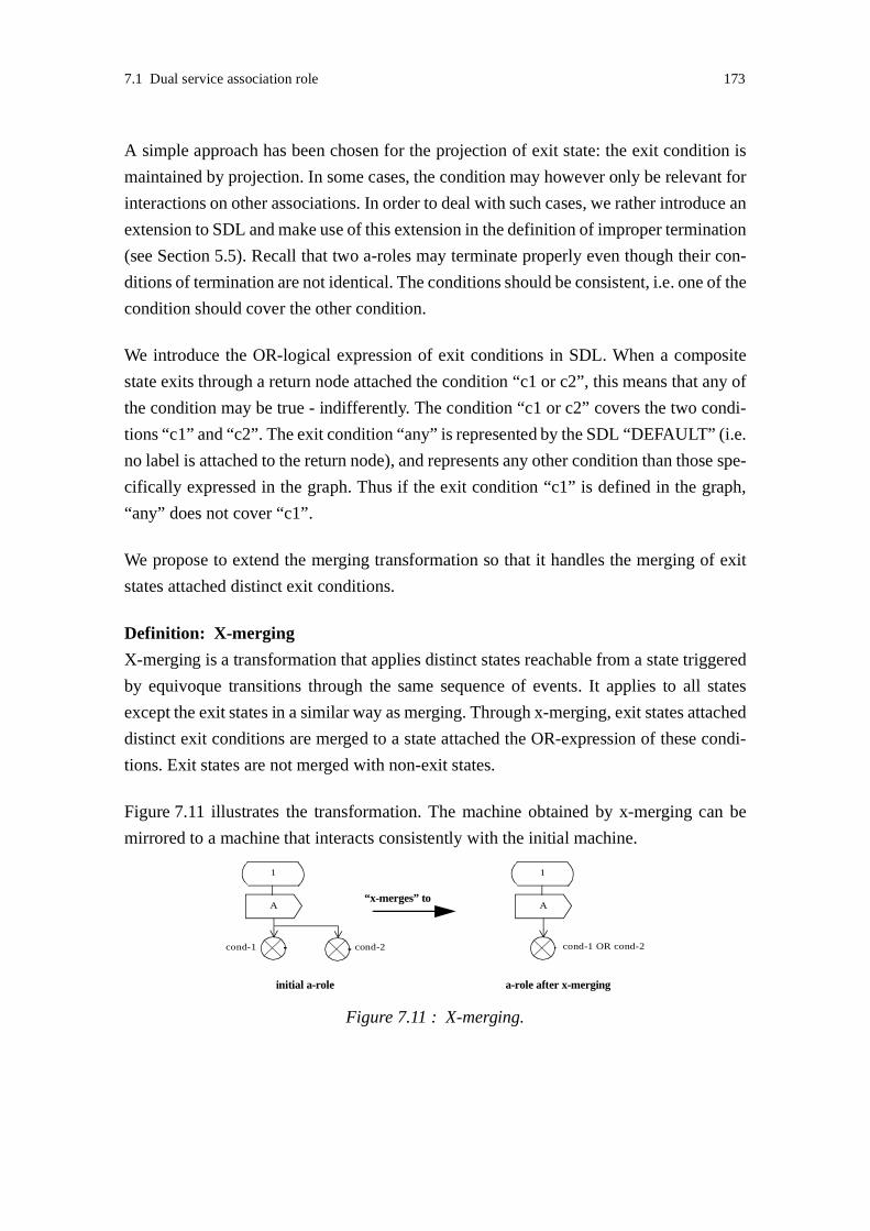
7.1 Dual service association role 173
A simple approach has been chosen for the projection of exit state: the exit condition is
maintained by projection. In some cases, the condition may however only be relevant for
interactions on other associations. In order to deal with such cases, we rather introduce an
extension to SDL and make use of this extension in the definition of improper termination
(see Section 5.5). Recall that two a-roles may terminate properly even though their con-
ditions of termination are not identical. The conditions should be consistent, i.e. one of the
condition should cover the other condition.
We introduce the OR-logical expression of exit conditions in SDL. When a composite
state exits through a return node attached the condition “c1 or c2”, this means that any of
the condition may be true - indifferently. The condition “c1 or c2” covers the two condi-
tions “c1” and “c2”. The exit condition “any” is represented by the SDL “DEFAULT” (i.e.
no label is attached to the return node), and represents any other condition than those spe-
cifically expressed in the graph. Thus if the exit condition “c1” is defined in the graph,
“any” does not cover “c1”.
We propose to extend the merging transformation so that it handles the merging of exit
states attached distinct exit conditions.
Definition: X-merging
X-merging is a transformation that applies distinct states reachable from a state triggered
by equivoque transitions through the same sequence of events. It applies to all states
except the exit states in a similar way as merging. Through x-merging, exit states attached
distinct exit conditions are merged to a state attached the OR-expression of these condi-
tions. Exit states are not merged with non-exit states.
Figure 7.11 illustrates the transformation. The machine obtained by x-merging can be
mirrored to a machine that interacts consistently with the initial machine.
Figure 7.11 : X-merging.
A
1
cond-1 cond-2
“x-merges” to
initial a-role a-role after x-merging
A
1
cond-1 OR cond-2

174 7 Interface validation
V-rule: X-merging and duality
The dual a-role of an a-role that contains equivoque transitions, but that
- does not present any input, mixed, termination ambiguity, and
- does not contain any acute τ-transitions, and
- does not contain any mixed initiative state,
can be obtained by mirroring the a-role obtained by transforming the initial a-role by x-
merging.
The initial a-role and the a-role obtained by x-merging and mirroring interact consistently
provided that
- they both start execution consistently, i.e. the machines should be entered using consist-
ent entry conditions, and
- any spontaneous sending can occur.
Justification:
This rule is based on the previous validation rule “"Merging and duality". Exit condition
ambiguity is added, and merging replaced by x-merging. We can follow the same reason-
ing as previously. “X-merging with save” preserves the observable behaviour except the
exit conditions. However the exit states after x-merging are attached an exit condition that
covers the initial exit conditions. That condition is maintained in the mirrored role, that
according to the definition of improper termination, will then interacts consistently with
the initial role.
Algorithm 7.4 is easily extended to x-merging so that exit states and their attached condi-
tions are merged. In the following, we will use the term merging instead of x-merging.
7.1.2.5 Strong ambiguities
As shown previously, it is not possible to specify dual a-roles for a-roles that present input,
mixed or termination ambiguity. Designers need therefore to re-specify the s-roles and a-
roles in order to remove the ambiguity. In this section, we propose simple design rules.
Designers may prefer to modify the state machine differently; designers’ choices may
depend on the application being designed.
D-rule: Removing input ambiguity
Input ambiguity should be removed. Input ambiguity in the a-role may be removed by
merging. When a-roles are derived from s-roles, re-design applies to s-roles.

7.1 Dual service association role 175
Figure 7.12 illustrates this design rule. The states where input divergence occurs are
merged to a new state that can consume any of the inputs of the states to be merged.
Algorithm 7.4 can be easily extended in order to remove input ambiguity in the a-role by
merging. States with input ambiguity were identified in Algorithm 7.3.
D-rule: Removing mixed ambiguity
Mixed ambiguity should be removed. Mixed ambiguity may be removed by merging.
When a-roles are derived from s-roles, re-design applies to s-roles. The states where
mixed ambiguity occur are merged to a mixed initiative state. The rules defined for mixed
initiative states should then be applied (see Section 7.1.3).
Figure 7.13 illustrates this design rule. The states where behaviour divergence occurs are
merged to a new state “2-3” that can consume any of the inputs and send any output of the
states to be merged. As we will see in Section 7.1.3, a dual state of the mixed initiative
state cannot be derived by simple mirroring. Algorithm 7.4 can be easily extended in
order to remove mixed ambiguity in the a-role by merging. States with mixed ambiguity
were identified in Algorithm 7.3.
Recall that merging should not be applied on machines that present termination ambigu-
ity. Exit states that have a particular semantics should not be merged with non-exit states.
Adding the sending of a signal before the exit state solves only partially the problem. This
Figure 7.12 : Re-design: removing input ambiguity.
A
2
1
B
3
C
4 5
A
2-3
1
B C
4 5
merges to
Figure 7.13 : Re-design: removing mixed ambiguity.
A
2
1
B
3
C
4 5
A
2-3
1
B C
4 5
merges to
mixed initiative state

176 7 Interface validation
is illustrated by the examples on Figure 7.14. In case a, the modified machine contains
equivoque transitions, but does not present any ambiguity. A dual association can be
obtained by merging and mirroring (see Section 7.1.2.3.3). In case b, the modified
machine presents a mixed ambiguity. The ambiguity may be removed by merging; how-
ever merging leads to an undesirable form of mixed initiative state; this is further
explained in Section 7.1.3.5.
D-rule: Removing termination ambiguity
Termination ambiguity should be removed. Adding the sending of a termination indica-
tion signal before the exit state is a satisfying solution in the case where the other state(s)
triggered by the other equivoque transition(s) defines (define) only outputs. Otherwise the
state machine should be re-defined; the rules specified for mixed initiative states may be
followed (see Section 7.1.3.5). When a-roles are derived from s-roles, re-design applies
to s-roles.
7.1.2.6 Weak input and mixed ambiguities
By definition of a dual a-role, the full behaviour of the initial a-role should be covered
through interaction between the a-role and the dual a-role. Observe that when we relax the
constraint of full behaviour, a consistent complementary a-role can be generated by an
extended mirroring transformation. The generated a-role interacts consistently with the
initial a-role, also when the state presenting a weak ambiguity is reached.
This is illustrated in Figure 7.15. The initial a-role presents a weak input ambiguity. This
a-role is first reduced in order to remove non-common input behaviours from the state pre-
senting ambiguity. Here the input “C” is removed. Then merging and mirroring can be
applied on the reduced a-role. The complementary a-role does not provide the full behav-
iour expected by the initial a-role. The behaviour “C” never occurs when these two roles
interact. It is not a dual a-role. We call it a “reduced” dual a-role.
Figure 7.14 : Re-design: removing termination ambiguity.
C
(a)
A
2
1
3
C
A
2
1
3
Exit
EXIT
A
2
1
B
(b)
3
A
2
1
B
3
Exit
EXIT
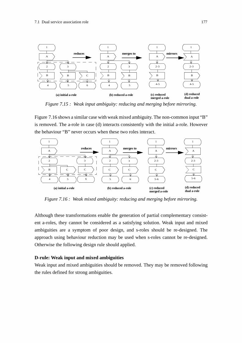
7.1 Dual service association role 177
Figure 7.16 shows a similar case with weak mixed ambiguity. The non-common input “B”
is removed. The a-role in case (d) interacts consistently with the initial a-role. However
the behaviour “B” never occurs when these two roles interact.
Although these transformations enable the generation of partial complementary consist-
ent a-roles, they cannot be considered as a satisfying solution. Weak input and mixed
ambiguities are a symptom of poor design, and s-roles should be re-designed. The
approach using behaviour reduction may be used when s-roles cannot be re-designed.
Otherwise the following design rule should applied.
D-rule: Weak input and mixed ambiguities
Weak input and mixed ambiguities should be removed. They may be removed following
the rules defined for strong ambiguities.
Figure 7.15 : Weak input ambiguity: reducing and merging before mirroring.
A
2
1
B
3
B C
4 5 6
A
2-3
1
B
4-5
reducesA
2
1
B
3
B
4 5
merges to
B
2-3
1
A
4-5
mirrors
(a) initial a-role (b) reduced a-role (c) reduced (d) reducedmerged a-role dual a-role
Figure 7.16 : Weak mixed ambiguity: reducing and merging before mirroring.
A
2
1
B
3
CC
4 5 6
A
2
1
3
CC
5 6
A
2-3
1
C
5-6
2-3
1
A
5-6
C
reduces merges to mirrors
(a) initial a-role (b) reduced a-role (c) reducedmerged a-role
(d) reduceddual a-role

178 7 Interface validation
7.1.3 Mixed initiatives
Mixed initiatives occur when an a-role and its complementary a-role both can take an ini-
tiative to send during the same interaction step. If two associated a-roles take the initiative
to send simultaneously, the signals may cross each other, and the a-roles perceive the
order of occurrence of events differently. This should be taken into account when speci-
fying a-roles. In state machines, mixed initiatives are represented by mixed initiative
states. This section define rules applying to such machines. Recall that mixed initiatives
may either represent concurrent behaviours or alternative orderings (see Section 6.6).
These two forms of mixed initiative require slightly different rules.
7.1.3.1 Input consistency
When two machines take the initiative to send simultaneously, the signals they send are
received in the states triggered by signal sending in the other machines. In order to avoid
unspecified signal reception, the signals specified as inputs in mixed initiative states
should be specified as inputs in the states following signal sending in the mixed initiative
states. This is a form of input consistency as described by [Bræk and Haugen 1993].
Definition: Input consistency
A state is input consistent with another state, if the set inputs enabled in this state contains
the set of inputs enabled in the other state. Two states are input consistent if they accept
the same set of inputs.
A simple example of input consistency is shown in Figure 7.17. The initial machine may
either take the initiative to send “A”, or may consume “B”. If the signals “A” and “B”
cross each other, the signal “B” is received while the machine is in state “2” leading to an
unspecified signal reception. To avoid this unspecified signal reception, the machine is
made input consistent, i.e. the signal “B” is added as input in state “2”. The behaviour
occurring in the new state “6” will be discussed in Section 7.1.3.2.
D-rule: Mixed initiative and input consistency
Any state triggered by an output from a mixed initiative state should be defined input con-
sistent with the mixed initiative state.
Justification:
We assume that any of the inputs specified in a mixed initiative state may be sent by the
complementary machine. Any of these inputs may be received after an output specified in

7.1 Dual service association role 179
the mixed initiative state is sent; this is the case when the signals cross each other. Thus,
in order to avoid unspecified signal reception, any of the inputs specified in a mixed ini-
tiative state should also be specified in any state triggered by an output from a mixed
initiative state.
Note that alternative event orderings as introduced in Section 6.6 enforces this design
rule.
Applying this design rule may lead to the introduction of new mixed initiative states. This
is the case if the successor state of the mixed initiative state defines some output. An
example is shown in Figure 7.18. Of course, in that case the rule should also be applied
on the successor state “4” of the new mixed initiative state “2”. Concurrent behaviours
that encompass successive sendings (as in this example “A”, “C”) may lead to complex
specifications and should be avoided; this is discussed in Section 7.1.3.2.2.
V-rule: Mixed initiative and input consistency
An a-role and its complementary a-role involved in a mixed initiative may interact in a
non-consistent way if their machines are not specified following the design rule “mixed
initiative and input consistency”.
Figure 7.17 : Mixed initiatives: input consistency.
1
BA
2 3
C D
4 5
(a) initial machine
1
BA
2 3
C D
4 5
B
6
(a) input consistent machine
inputconsistency
makesinput consistent
Figure 7.18 : Mixed initiative state introduced by input consistency.
1
BA
2 3
C
4
B
5
input consistency
new mixed initiative

180 7 Interface validation
Justification:
As both a-roles are involved in a mixed initiative, they may both take initiative to send a
signal. If they take the initiative to send simultaneously, the signals are received in the
states triggered by sending from the mixed initiative states. If these states are not input
consistent with the mixed initiative states as recommended by the design rule, unspecified
signal receptions occur: the a-roles do not interact consistently.
Note that it is possible to produce a consistent complementary a-role for an a-role whose
machine contains a mixed initiative state, but does not follow the design rule “mixed ini-
tiative and input consistency”. The a-roles interact consistently when the complementary
a-role is not enabled to take an initiative in the complement state of the mixed initiative
state. In that case, the full behaviour expected by the a-role is not covered.
7.1.3.2 Concurrent behaviours: conflict resolution
In the case of concurrent behaviours, conflicts may occur. State machines should be spec-
ified such that conflicts can be detected and resolved. In this section, we propose some
design patterns for the resolution of conflicts.
Conflicts occur when a machine and its complementary machine send signals to each
other simultaneously. A conflict is perceived when an input specified in a mixed initiative
state is received in the state following signal sending in the mixed initiative state. A con-
flict can be detected in both interacting machines. Enforcing the input consistency design
rule provides a means to detect conflicts.
Machines involved in a conflict should agree on how to further proceed. The purpose of
conflict resolution is to come to an agreement. Conflict resolution requires coordination
between the interacting machines. Two main coordination patterns may be defined:
• A coordinator may be assigned at design time. An example is described in Figure 7.19.
The machine on the left-hand side coordinates the conflict resolution. The signal
“resolve” represents the decision taken at conflict resolution. For example, the signal
“D” may be sent if the behaviour (“B”, “D”,...) is retained. Note that the machine and
the complementary machine interact consistently. This can be checked by considering
all possible behaviours. We observe that the states where the conflict is detected, i.e.
state “2” in the machine (a) and state “3” in the complementary machine (b), do not
mirror their complement states. The states describing conflict resolution, i.e. state “6”
in both machines, mirror each other.
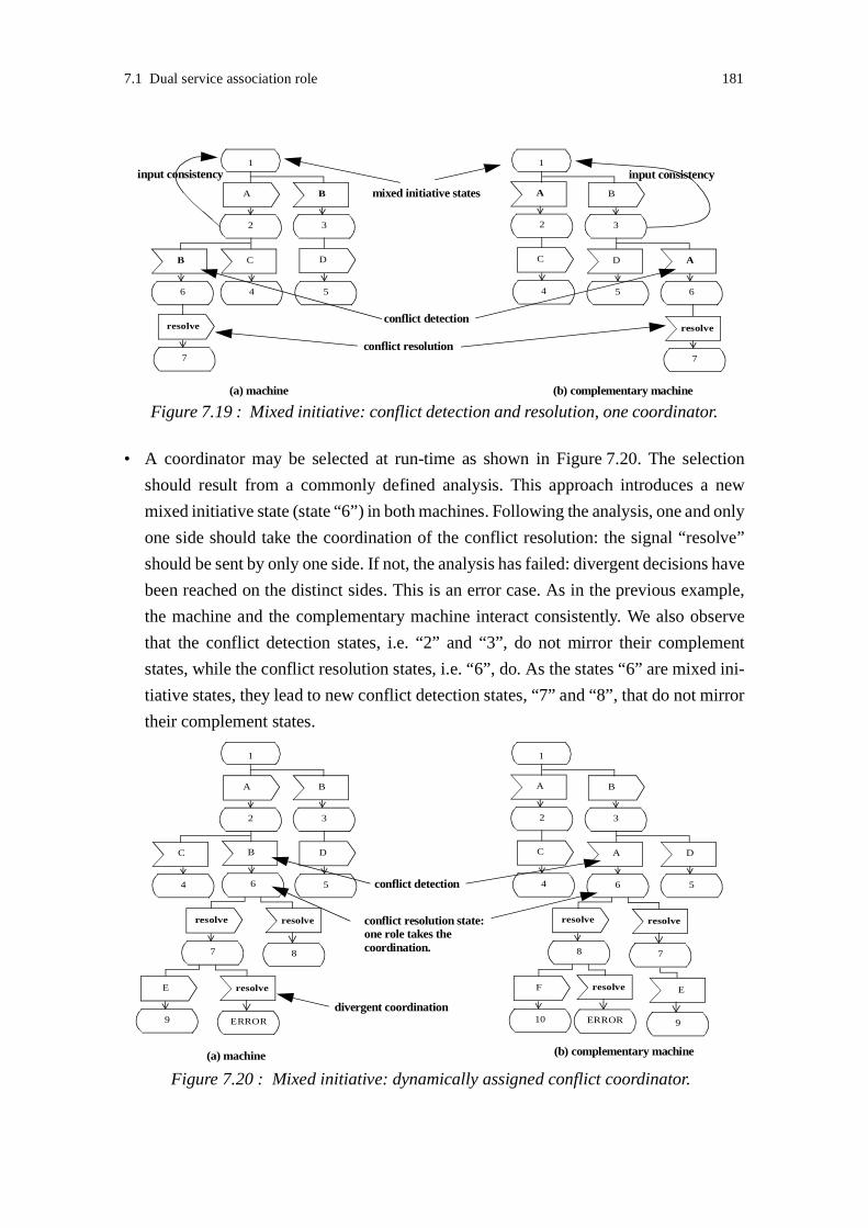
7.1 Dual service association role 181
• A coordinator may be selected at run-time as shown in Figure 7.20. The selection
should result from a commonly defined analysis. This approach introduces a new
mixed initiative state (state “6”) in both machines. Following the analysis, one and only
one side should take the coordination of the conflict resolution: the signal “resolve”
should be sent by only one side. If not, the analysis has failed: divergent decisions have
been reached on the distinct sides. This is an error case. As in the previous example,
the machine and the complementary machine interact consistently. We also observe
that the conflict detection states, i.e. “2” and “3”, do not mirror their complement
states, while the conflict resolution states, i.e. “6”, do. As the states “6” are mixed ini-
tiative states, they lead to new conflict detection states, “7” and “8”, that do not mirror
their complement states.
Figure 7.19 : Mixed initiative: conflict detection and resolution, one coordinator.
1
BA
2 3
C D
4 5
mixed initiative states
1
A B
32
DC
54
(a) machine (b) complementary machine
B
6
resolve
7
A
6
resolve
7
conflict detection
conflict resolution
input consistency input consistency
Figure 7.20 : Mixed initiative: dynamically assigned conflict coordinator.
1
BA
2 3
C D
4 5
1
A B
32
AC
64
(a) machine (b) complementary machine
B
6
D
5conflict detection
resolve
7 7
resolveconflict resolution state: resolve
88
resolve
E
9 ERROR
resolve F
10 ERROR
resolve
divergent coordination
one role takes thecoordination.
9
E

182 7 Interface validation
D-rule: Mixed initiative and conflict
In the case where a mixed initiative state describes concurrent behaviours, a behaviour
conflict is detected when some state following signal sending in a mixed initiative state
receives a signal specified as input in the mixed initiative state. Conflict resolution
requires coordination. A conflict resolution coordinator can be assigned either at design
time or at run-time.
7.1.3.2.1 Negotiation
The selection of a coordinator at run-time may be refined by adding a negotiation phase.
This is shown in Figure 7.21. Conflict resolution does not take place at once, but after a
negotiation leading to the selection of a coordinator. In this example, negotiation is initi-
ated by both sides; this introduces new mixed initiative states “1n”. Note that these new
mixed initiative states represent alternative orderings, not concurrent behaviours. These
states and their successors “2n” mirror their complement states; the alternative orderings
lead to the common state “3n” and its complement state “3n”.
Figure 7.21 : Mixed initiative: negotiation.
1
BA
2 3
C D
4 5
1
A B
32
DC
54
(a) machine (b) complementary machine
B
1n
negotiate-A
2n
A
1n
2n
conflict detection
negotiation
negotiate-Bnegotiate-B negotiate-A
negotiate-B negotiate-A
3n
6
resolve
7
3n
negotiate-A negotiate-B
6
7
resolve
} {conflict resolution state:
resolve
88
resolve
E
9 ERROR
resolve F
10 ERROR
resolvedivergent
one role is assignedcoordination.
coordination assignment

7.1 Dual service association role 183
7.1.3.2.2 Signal sending sequences
A particular case occurs when a concurrent behaviour describes the sending of a sequence
of signals. The detection of conflict may occur at any step in the sending sequence.
An example is shown in Figure 7.22. The signals “A” and “C” may be sent successively.
If both machines take initiative simultaneously, the signal “B” may either be received
before or after the sending of “C”. The conflict is perceived by the machine in state “2”
or “4” when “B” is received. In the complementary machine, the conflict may either be
detected by the reception of “A” or “C”. On entering the state “1d”, the complementary
machine is not able to determine whether the signal “C” has been sent or not. In order to
avoid the introduction of a new mixed initiative state, the conflict resolution should be
coordinated by the machine. If multiple sendings can take place after the sending of “A”,
new conflict detection and resolution states are added in a cascade manner. As the struc-
ture of the state graph is not preserved in the complementary machine, the relations
between the conflict resolution states of the machine and the complementary machine
may become very complex.
In this example, the machine in case (a) is able to determine at which step in the sending
sequence the conflict occurs. When both machines are able to send a sequence of signals,
the conflict detection becomes cumbersome. An example is shown in Figure 7.23. The
different conflict detection states correspond to different conflict sequences. The same
names are used in both machines for the identical conflict sequences. For example, the
states “3d” correspond to signals “B”, “D” crossing “A”. On entering the state “1d”, none
of the machine is not able to determine whether the second signal in the sequence has been
Figure 7.22 : Concurrent behaviours: sending sequence.
1
BA
2 3
D
5
1
A B
32
D
E
5
6
(a) machine (b) complementary machine
B
1d
A
1d
resolve
1r
C
4
E
6
B
2d
C
4
C
2d
resolve
5

184 7 Interface validation
sent or not. Therefore the conflict cannot be resolved without the introduction of a new
mixed initiative state. On the other hand, on entering the state “2d”, the machine is not
able to determine whether the signal “D” has been sent or not. On entering the state “3d”,
the complementary machine is not able to determine whether the signal “C” has been sent
or not. In these states mixed initiatives may be avoided. As shown by this example, the
structure of the graph becomes complex and it is cumbersome to establish the relations
between conflict detection states when multiple sendings are allowed in a mixed initiative
state.
We recommend to avoid specifications that make the specification of the dual machine
difficult, and that do not maintain simple relations between the conflict detection states of
the machine and the complementary machine. We advice to avoid sending sequences in
concurrent behaviours.
D-rule: Mixed initiative and signal sending sequences
Concurrent behaviours described by mixed initiatives should not specify signal sending
sequences. Signal sending and consumption should take place alternatively.
As a consequence of this rule, signal reception sequences do not occur.
Figure 7.23 : Concurrent behaviours: multiple conflict detection states.
1
BA
2 3
5
1
A B
32
E
5
6
(a) machine (b) complementary machine
B
1d
A
1d
C
4
E
6
B
2d
C
4
C
2d
DD
A
3d
C
4d
D
3d
D
4d

7.1 Dual service association role 185
7.1.3.3 Alternative input and output event orderings
A mixed initiative behaviour that describes alternative input and output event orderings
has the following characteristics:
• The same set of events take place in the alternative sequences. The sequences differ in
their ordering of events.
• A machine and its complementary machine may perceive different input and output
orderings. As interactions on an association are sent over a single communication path,
inputs are received in the same order as sent.
• The same behaviour takes place after any of the alternative sequences. Thus the alter-
native sequences lead to a common state.
Alternative event orderings do not require conflict resolution. The main concern during
validation is to ensure that the sequences lead to the same state.
Figure 7.24 illustrates an example where the sequences lead to distinct states (state “4” or
“5”); we assume these states to be non-equivalent. A machine that sends a signal before
it receives a signal, is not able to determine the event ordering chosen at the other
machine. For example, when in state “4”, the machine in case (a) cannot determine if the
complementary machine has reached state “4” or “5”. When two machines send signals
to each other simultaneously (signal crossing), none of them is able to determine the event
ordering at the complementary machine, and further behaviour is not predictable. This
ambiguity may be removed by letting the machines exchange some status information.
One machine should coordinate this ambiguity resolution, otherwise new mixed initiative
states are introduced. This approach introduces extra signalling, and any optimisation
benefit gained from letting the machines communicate in any order is lost.
Figure 7.24 : Alternative input and output event orderings: ambiguity.
A
1
2
B
4
A
1
2
4
B A
3
5
BB
3
A
5
(a) machine (b) complementary machine
distinct states

186 7 Interface validation
D-rule: Input/output event orderings and further behaviour
Alternative input/output event orderings should lead to a common state.
Alternative input/output events orderings may involve more than two events. An example
is shown in Figure 7.25. Notice that the input consistency rule is enforced. When more
than two events are introduced, the state graph becomes complex, and the identification
of orderings cumbersome. We advice therefore to avoid using multiple event orderings
except in special cases, such as negotiation or error indication, and to limit the number of
events to two in the sequences.
D-rule: Input/output event orderings and event sequence length
The event sequence in alternative input/output event orderings should not contain more
than two events, i.e. one input and one output.
Note that this design rule does not restrict the number of events sent or received in a state
to two. The mixed initiative state may specify several input and output events. Only the
length of sequence is restricted.
Differently from concurrent behaviours, the dual machine of a machine describing alter-
native event orderings mirror each other. The negotiation phase in the example shown in
Figure 7.21 illustrates this property.
Figure 7.25 : Event ordering: four events.
B
2
3
C
4
C
7
B
8
A
1
D
5
B
9
A
10
C
11
D
5
D
5
D
6
C
5
D
12
C
5
A
14
C
5
D
13

7.1 Dual service association role 187
7.1.3.4 Concurrent behaviours and input/output event ordering
A particular case occurs when a signal specified as input in a mixed initiative state can
also be consumed “normally” in a state following signal sending in the mixed initiative
state. By “normally”, it is meant that the input is not specified in order to enforce input
consistency, but is part of a normal behaviour. This input may either occur first in the
mixed initiative state, or after sending a signal.
An example is shown in Figure 7.26. The signal “B” may either be consumed in the mixed
initiative state “1”, or after sending “A” in state “2”. In the complementary machine the
sending of “B” may occur after the consumption of “A”. However, when “B” is received
in the machine in state “2”, we cannot deduce that “B” was sent after “A”; “B” may also
has been sent by the complementary machine in state “1” meaning that the two machines
have taken conflicting initiatives. We observe that only the complementary machine is
able to detect whether a “normal” behaviour or a conflict has occurred. The machine is
not able to distinguish state “4” from state “7” in the complementary machine. This is a
form of ambiguity that is cognate to the ambiguity introduced by equivoque transitions.
A simple way to remove any ambiguity is to define the states “4” and “7” identical. This
corresponds to the case of alternative input/output event orderings. If states “4” and “7”
are kept distinct, they should lead to further behaviours that are distinguishable. For exam-
ple, distinct signals may be sent in the transitions from the states “4” and “7” of the
complementary machine. The state “4” of the machine should be able to consume any of
these signals.
In this example, the complementary machine can easily detect the occurrence of a con-
flict. In the case where both machines define “normal” behaviours that may be mistaken
for concurrent behaviours, the conflict detection becomes cumbersome. An example is
shown in Figure 7.27. If the machine is in state “4”, and the complementary machine in
state “7”, none of the machines can deduce immediately that a conflict has occurred. An
Figure 7.26 : Concurrent behaviours and event ordering.
1
BA
2 3
C D
5 6
1
A B
32
DC
65
(a) machine (b) complementary machine
B
4
A
7
conflict
B
4
normal casenormal caseor conflict?

188 7 Interface validation
interaction is needed to do so. A simple approach is to define the states “4” and “7” iden-
tical dealing with the case as alternative orderings.
We recommend to avoid specifications that make the detection of conflicts difficult, or the
specification of states following the conflict detection dependent of other states. Mixed
initiatives should either describe concurrent behaviours or alternative orderings.
D-rule: Mixed initiative purposes
Mixed initiatives should either describe concurrent behaviours or alternative orderings,
not both.
7.1.3.5 Exit states
A special case of mixed initiative occurs when the successor state of the mixed initiative
after signal sending is an exit node. As an exit state has no successor, the design rule
“mixed initiative and input consistency” cannot be followed.
An example is given in Figure 7.28. In the case where a mixed initiative takes place, the
signal “A” arrives when the machine has stopped. The conflict can be detected in the com-
plementary machine. Only one choice is open to avoid improper termination: the
complementary machine should terminate. In this example, although the signal “A” may
be lost, the termination is done properly, and the a-role interaction is considered as
consistent1.
In some cases, mixed initiatives may lead to improper termination as shown in
Figure 7.29. In this example, both behaviours lead to exit nodes attached distinct exit
conditions.
1. Our definition of interaction consistency does not encompass the loss of signal.
Figure 7.27 : Concurrent behaviours: ambiguous conflict.
1
BA
2 3
C D
5 6
1
A B
32
DC
65
(a) machine (b) complementary machine
B
4
A
7
B
4
normal casesnormal caseor conflict?
A
7
normal caseor conflict?

7.1 Dual service association role 189
V-rule: Mixed initiative and termination
An a-role and its complementary a-role involved in a mixed initiative leading to exit
nodes attached distinct exit conditions, may interact inconsistently.
Justification:
As both a-roles are involved in a mixed initiative, they may both take initiative to send a
signal. If they take the initiative to send simultaneously in the mixed initiative states pre-
ceding the exit nodes, they terminate with inconsistent exit conditions. Such interaction
leads to improper termination: the a-roles do not interact consistently.
Note that it is possible to produce a dual a-role for an a-role whose machine contains a
mixed initiative state followed by exit nodes with distinct exit conditions. For example,
the a-roles interact consistently when the complementary a-role is not enabled to take an
initiative in the complement state of the mixed initiative state. In that case the dual a-role
does not provide the full behaviour expected by the a-role.
Although consistent, the kind of behaviour shown in Figure 7.28 is problematic when s-
roles are composed. Signal “A” may be received by an s-role executing after the termina-
tion of the s-role providing the a-role described in case (a). S-roles should be specified
without making too many assumptions about the s-roles they are composed with. The fol-
lowing design rule contributes to this aim.
Figure 7.28 : Mixed initiative: termination.
1
A
2
B
1
B
2
A
B(a) machine
(b) complementary machine
Figure 7.29 : Mixed initiative: improper termination.
1
A B
1
BA
(a) machine (b) complementary machine
success fail failsuccess

190 7 Interface validation
D-rule: Mixed initiative and termination
A-roles should be designed such that exit states do not directly succeed any mixed initia-
tive state.
7.1.3.6 Specifying a dual a-role
After this discussion about the desirable properties of an a-role whose machine contains
mixed initiative states, we now proceed to produce a dual a-role for such an a-role. As the
the full behaviour of the a-role can be covered through interaction between the a-role and
the dual a-role, any mixed initiative behaviour specified in the a-role may occur.
We assume that input, mixed and termination ambiguity have been removed (see
Section 7.1.2.5). We also assume that the design rules defined for mixed initiatives have
been followed. Recall these design rules:
• "Mixed initiative and termination" on Page 190
• "Mixed initiative purposes" on Page 188
• "Mixed initiative and input consistency" on Page 178
• "Mixed initiative and conflict" on Page 182
• "Mixed initiative and signal sending sequences" on Page 184
• "Input/output event orderings and further behaviour" on Page 186
• "Input/output event orderings and event sequence length" on Page 186
V-rule: Event ordering and duality
The dual a-role of an a-role that
- does not present any input, mixed and termination ambiguity, and
- does not contain any acute τ-transitions, and
- does not present any mixed initiative that describes concurrent behaviours, and
- enforces the design rules defined for mixed initiatives,
can be obtained by merging and mirroring.
The initial a-role and the a-role obtained by this transformation interact consistently pro-
vided that
- they both start execution consistently, i.e. the machines should be entered using consist-

7.1 Dual service association role 191
ent entry conditions, and
- any spontaneous sending can occur.
Justification:
Reasoning is performed on all states, except the mixed initiative states and their succes-
sors, in the same manner as for machines that do not contain mixed initiative states. Each
state is merged/mirrored to a consistent state, and transitions from those states preserve
consistency.
When mirroring mixed initiative states to complement states, we ensure that the states
interact consistently with the complement states when initiatives are not taken simultane-
ously by both sides. The states following the mixed initiative states mirror each other and
thus interact consistently.
If initiatives are taken simultaneously, the sent signals cross each other:
- As we assume that the event sequence length is restricted to two, and as the mixed initi-
atives do not describe any concurrent behaviours, no other signal than the signals sent in
the mixed initiative state and its complement mixed initiative state may cross.
- In the initial machine, input consistency ensures that the next state after sending is ena-
bled to consume the crossing signal sent by the other machine.
- As the event sequence length is restricted to two, any signal that may be sent in the mixed
initiative state may also be sent in the next state after consumption of a signal in a mixed
initiative state. When mirrored these transitions enforce input consistency in the comple-
mentary machine: any signal that may be consumed in the complement mixed initiative
state may also be consumed in the next state after sending a signal. Input consistency in
the complementary machine ensures that the next state is enabled to consume any crossing
input.
Thus we can deduce that the machine interact consistently with the complementary
machine in any state following the mixed initiative state. Both orderings lead to a common
state in the initial machine that is mirrored to a common complement state. This common
state is either a non-mixed initiative state and is consistent with is complement state, or a
mixed initiative state representing new alternative orderings and the previous reasoning
can be repeated.
V-rule: Mixed initiative and duality
The dual a-role of an a-role that
- does not present any input, mixed and termination ambiguity, and
- and does not contain any acute τ-transitions, and
- enforces the design rules defined for mixed initiatives,

192 7 Interface validation
can be obtained by merging and mirroring all states, except the states following mixed ini-
tiative states that represent concurrent behaviours. Such states should be transformed as
followed:
- A state following signal sending is transformed to a complement state. Any signal and
transition from the state that do not serve conflict detection are transformed by mirroring.
The consumption of any signal enabling the detection of a conflict in the a-role is not mir-
rored. As conflict detection is defined relative to the preceding mixed initiative state,
distinct complement states are generated for states that have several predecessors.
- A state following signal consumption is transformed to a complement state. Any signal
and transition in that state are transformed by mirroring. The complement state is made
input consistent with its preceding mixed initiative state. The state following the con-
sumption of a signal enabling the detection of a conflict in the complementary a-role
mirrors the next state after the detection of the same conflict in the initial a-role.
The initial a-role and the a-role obtained by this transformation interact consistently pro-
vided that
- they both start execution consistently, i.e. the machines should be entered using consist-
ent entry conditions, and
- any spontaneous sending can occur.
Justification:
Reasoning is performed on all states, except the mixed initiative states and their succes-
sors, in the same manner as for machines that do not contain mixed initiative states.
Reasoning on mixed initiative states that represent alternative event orderings has been
done above. As we assume that mixed initiative states either describe concurrent behav-
iours or alternative orderings, we just need to reason on concurrent behaviours.
By mirroring mixed initiative states to a complement state, we ensure that the states inter-
act consistently with the complement state when initiatives are not taken simultaneously
by both sides. The states following the mixed initiative states can also be shown to interact
consistently in that case:
- If the initiative was taken by the initial a-role, only the complementary a-role is enabled
to send some signal, this because of the rule "Mixed initiative and signal sending
sequences". The complementary a-role is only enabled to send signals expected by the ini-
tial machine, this because we have restricted mirroring to signals not involved in conflict
detection. Here note the importance of generating distinct successors for distinct mixed
initiatives.
- If the initiative was taken by the complementary a-role, only the initial a-role is enabled
to send some signal, this because of the rule "Mixed initiative and signal sending

7.1 Dual service association role 193
sequences". As the states triggered by signal consumption have been transformed by mir-
roring, the complementary a-role can consume the signals sent by the initial a-role.
In the case where both a-roles take the initiative to send simultaneously, the signals cross
each other:
- As we assume that no successive signal sendings occur in a concurrent behaviour, only
two signals may cross each other.
- The consumption of these signals is enforced as both machines follow the input consist-
ency design rule. The conflict is detected in both machines. As the behaviours occurring
after conflict detection complement each other, the machines interact consistently after
the detection of a conflict.
The transformation described by the rule does not require distinct complement states to
be generated for states succeeding the mixed initiative state after signal consumption. The
generation of distinct states would however ensure that the complement state is not ena-
bled to consume more signals than strictly necessary.
Given this validation rule, we are able specify an algorithm that generates a dual a-role for
an a-role containing mixed initiative states. Before the generation of a dual a-role, the
mixed initiative states should be identified, and the machine should be checked against
the design rules defined for mixed initiatives. Algorithm 7.6 performs these operations.
The algorithm considers first a mixed initiative state as an alternative ordering. If the rule
"Mixed initiative purposes" is not enforced, an error is generated when checking the
ordering sequences. We assume that the graph has been minimized (Algorithm 6.1), and
that merging has been applied in order to remove input, mixed and termination ambiguity.
The algorithm makes use of the notation introduced in Section 6.8.
Algorithm 7.6: Identifying mixed initiative states and checking design rules
main (){/* Assumptions:
- the graph has been minimized*/
/* set of mixed initiative states */CB = {}; /* conflicting behaviours*/AO = {}; /* alternative orderings*/
W = {}; /* working set */

194 7 Interface validation
/* start from all initial states */for each so in Soif so is not in W
identify-mixed-state (so);
/* design rule: "Mixed initiative and termination"*/for each s in AO or CB
check-termination (s);
/* design rule: "Mixed initiative and input consistency"*/for each s in AO or CB
check-input-consistency (s);
/* design rules:"Input/output event orderings and further behaviour"and"Input/output event orderings and event sequence length"*/for each s in AO
check-I/O-orderings (s);
/* design rule:"Mixed initiative and signal sending sequences" */for each s in CB
check-sending-sequence (s);
}
identify-mixed-state (s){add s to W;
if input-enable (s) is not emptyand output-enable (s) is not empty /* mixed state */for each i in input-enable (s)n = T (s, i);/* seek after event permutation */if some o in output-enable (s) belongs to enable (n)add s to AO; /* alternative orderings */
if s is not in AOadd s to CB;
for each e in enable (s)for each successor n of s /* element of T (s, e) */if n is not in Widentify-mixed-state (n);
}
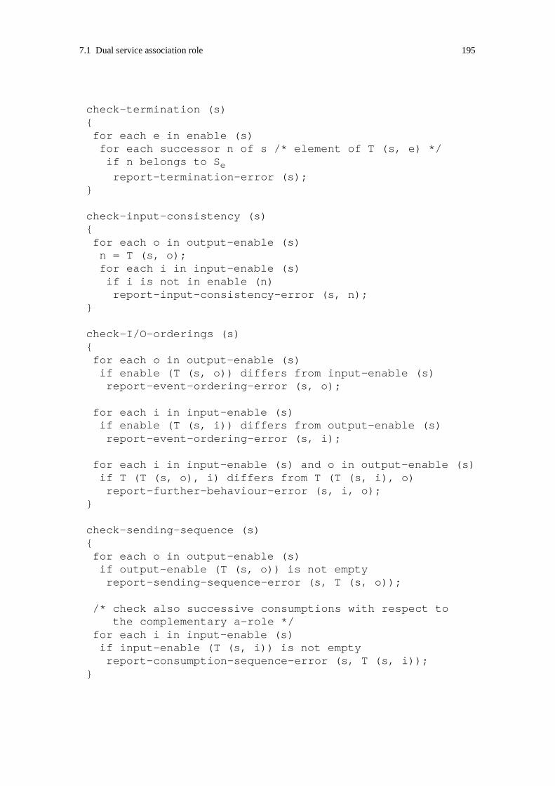
7.1 Dual service association role 195
check-termination (s){for each e in enable (s)for each successor n of s /* element of T (s, e) */if n belongs to Sereport-termination-error (s);
}
check-input-consistency (s){for each o in output-enable (s)n = T (s, o);for each i in input-enable (s)if i is not in enable (n)report-input-consistency-error (s, n);
}
check-I/O-orderings (s){for each o in output-enable (s)if enable (T (s, o)) differs from input-enable (s)report-event-ordering-error (s, o);
for each i in input-enable (s)if enable (T (s, i)) differs from output-enable (s)report-event-ordering-error (s, i);
for each i in input-enable (s) and o in output-enable (s)if T (T (s, o), i) differs from T (T (s, i), o)report-further-behaviour-error (s, i, o);
}
check-sending-sequence (s){for each o in output-enable (s)if output-enable (T (s, o)) is not emptyreport-sending-sequence-error (s, T (s, o));
/* check also successive consumptions with respect tothe complementary a-role */
for each i in input-enable (s)if input-enable (T (s, i)) is not emptyreport-consumption-sequence-error (s, T (s, i));
}

196 7 Interface validation
Algorithm 7.7 enables one to generate a dual a-role of an a-role that does not present any
input, mixed and termination ambiguity, and enforces the design rules defined for mixed
initiatives. It also assumes that the a-role does not contain any acute τ-transitions. The
mixed initiative states are identified by applying Algorithm 7.6. A machine that contains
equivoque transitions should be transformed by merging (Algorithm 7.4). Note that a new
complement state is generated for each state following a mixed initiative state. As conflict
detection is relative to the preceding mixed initiative, this ensures that the proper signals
are transformed by mirroring.
Algorithm 7.7: Generating a dual a-role
main (){/* Assumptions:
- the graph has been minimized- no input,mixed or termination ambiguity- no acute τ-transitions- mixed initiative states have been identified- mixed initiative rules are enforced- merging has been applied
*//* Mixed initiative states represented concurrentbehaviours are stored in CB (Algorithm 7.6) */
/* define graph elements: states and events */S = S; /* maintain any associated condition */I = I; O = O;
/* set of mirrored or transformed states */W = {};
/* start from all initial states */for each so in Soif so is not in W
mirror (so);
}
mirror (s){add s to W;for each e in E
define T(s, e) = T (s, e);

7.1 Dual service association role 197
if s is not in CB for each successor n of sif n is not in Wmirror (n);
elsegenerate-initiative-successors (s);
}
generate-initiative-successors (s){/* transform states after signal sending */for each o in output-enable (s)create new state x; /* add x to S */
set T(s, o) = x;
for each e in E /* initialise */
define T(x, e) = {};
for each i in input-enable (T(s, o))if i is not in enable (s)
set T(x, i) = T( T(s, o), i);
/* transform states after signal consumption */for each i in input-enable (s)create new state x; /* add x to S */
set T(s, i) = x;
for each e in E /* initialise */
define T(x, e) = {};
for each o in output-enable (T(s, i)) /* mirror */
set T(x, o) = T( T(s, i), o);
for each o in output-enable (s) /* input consistency */
set T(x, o) = T( T(s, o), i);
/* proceed in the graph */for each successor of successor n of s /* T (T(s, e), e) */if n is not in Wmirror (n);
}

198 7 Interface validation
7.1.4 Acute τ-transitions
Finally after equivoque transitions and mixed initiatives, complexity is added to the a-role
graphs by introducing acute τ-transitions. Acute τ-transitions often lead to ambiguity, but
not always. The validation rules related to input and mixed ambiguity introduced in
Section 7.1.2.1 apply. It is not possible to produce dual a-roles when τ-transitions lead to
ambiguity.
This section proposes two kinds of techniques:
• Re-design of the s-roles following design rules that enable remaining τ-transitions to
removed from the a-role state graph.
• Transformations that ensure that a dual a-role can be generated even though some τ-
transitions are not removed.
Notice that re-design towards the removal of τ-transitions applies to s-roles. As τ-transi-
tions in the a-role graphs are obtained by projection of non-visible interactions in the s-
role graphs, their removal require re-design the s-roles.
Acute τ-transitions are τ-transitions that have not been removed by gathering from the a-
role because their removal would modify the observable behaviour. Recall that we have
proposed two definitions of gathering: strong and weak gathering. Strong gathering main-
tains the machine observable behaviour in any case. Weak gathering only maintains the
observable behaviour provided that the spontaneous transitions can occur. We reconsider
any case of non-gathering in our reasoning. When a τ-transition is not removed by strong
gathering, potential errors that can be introduced by weak gathering are considered.
τ-transitions remain in the graph in the following cases (the cases where τ-transitions can
only be removed by weak gathering are marked by *):
1. A signal specified as an input in the τ-successor is not specified as input or save* in the
τ-predecessor.
2. A signal specified as an input in the τ-successor is specified as input in the τ-predeces-
sor, but the τ-successor and τ-predecessor transit to distinct successor states.
3. A signal specified as an input in the τ-successor is specified as save in the τ-predeces-
sor, but other inputs are also specified in the τ-predecessor.*
7.1 Dual service association role 199
4. A signal specified as a save in the τ-successor is not specified as input* or save in the
τ-predecessor.
5. A signal specified as a save in the τ-successor is specified as input in the τ-predecessor,
but other inputs are also specified in the τ-successor.*
6. A signal specified as an input in the τ-predecessor is not specified as input in the τ-
successor.
7. A signal specified as an input in the τ-predecessor is specified as input in the τ-succes-
sor, but the τ-successor and τ-predecessor transit to distinct successor states.
8. A signal specified as a save in the τ-predecessor is not specified as input* or save in the
τ-successor.
9. A signal specified as a save in the τ-predecessor is specified as input in the τ-successor,
but other inputs are also specified in the τ-predecessor.*
10.When the τ-transitions links an exit state with a non-exit state. This case leads to ter-
mination occurrence ambiguity (see Section 6.7.4).
Figure 7.30 to Figure 7.33 and Figure 7.37 illustrate the different cases. We have grouped
cases that may be handled in a similar way.
Recall that σ-states never precede or succeed τ-transitions, and thus, save is always
explicitly specified in τ-successors and τ-predecessors.
7.1.4.1 Re-design towards the removal of τ-transitions
7.1.4.1.1 Input consistency
Figure 7.30 illustrates the case (6) where a signal specified as input in a τ-predecessor is
not specified as input in the τ-successor. Here an external observer cannot determine when
the machine is enabled to handle the signal “A”. This is a form of input inconsistency. The
machine can be re-designed specifying “A” as input in the τ-successor.
Specifying “A” as save (instead of input) in the τ-successor is an alternative approach that
at the first glance seems simpler. However as the rule "Save consistency" is enforced, “A”
has to be specified as input in some successor states of state “3”. This may require other
modifications to be done to the graph. In the case where this alternative using save is cho-

200 7 Interface validation
sen, the τ-transition from state “2” to “3” in Figure 7.30 is only removed by weak
gathering. Gathering may hide a potential deadlock in state “2”. The designer should con-
sider the s-role behaviour projected to that τ-transition before applying weak gathering.
We recommend to choose the alternative using input. In this alternative, “A” can be con-
sumed in any state.
D-rule: τ-transitions and input consistency
A signal input should be re-iterated in the successor states of a state where input is spec-
ified, when the transitions to these successors describe non-visible interactions1. The
successor states should then be input consistent with the state where input is specified.
This rule does not set any constraint on the successor state triggered by the added input
and may lead to the case (7) illustrated in Figure 7.33.
It may be possible to produce a consistent complementary a-role of an a-role that does not
follow the rule. This is the case when the machine can further proceed without consuming
the signal whose input is not re-iterated. In case (6) in Figure 7.30, the machine may pro-
ceed in state “3” by sending a visible signal. Then, a complementary machine that ignores
“A” may interact consistently with the machine. Input inconsistency is however a symp-
tom of poor design, and the corresponding s-roles should be re-designed.
The rules "τ-transitions and input consistency" and "Mixed initiative and input consist-
ency" are cognate. In the first rule, successor states are triggered by transitions that
describe non-visible interactions. In the second rule, successor states are triggered by non-
visible signals, but do send some visible signal. We propose to define a single rule:
D-rule: Input consistency
A signal input should be re-iterated in the successor states of a state where input is spec-
ified, when the transitions to these successors are triggered by non-visible signals. The
1. i.e. the transitions are triggered by non-visible signals and do not send any visible signal.
Figure 7.30 : Acute τ-transitions withdrawn through input consistency.
1
2
3
A
4
(6)
add input “A”
τ
τ

7.1 Dual service association role 201
successor states should then be input consistent with the state where input is specified.
In the following, we assume that s-roles are designed according to the rule "Input
consistency".
7.1.4.1.2 Backward save and input consistencies
Figure 7.31 illustrates the cases (1), (4) and (8) where an external observer cannot deter-
mine when the machine is enabled to handle a received signal. Note that case (8) is an
error case as we assume that s-roles are designed according to the rule "Save consistency".
In case (4), the machine can be simply re-designed adding “A” as save in the τ-predeces-
sor. Adding save enforces backward save consistency. The τ-transition from state “1” to
“2” can then be removed by strong gathering.
In case (1), the machine can be re-designed adding “A” as save or input in the τ-predeces-
sor. The alternative using save is simple but the τ-transition from state “1” to “2” can then
only be removed by weak gathering. The alternative using input usually requires more
complex modifications to be made in the graph. Again the designer should consider the s-
role behaviour projected to that τ-transition before applying weak gathering.
We introduce two design rules "Backward input consistency" and "Backward save con-
sistency". Depending on the s-role behaviour projected to τ-transitions, the designer can
select which rule is appropriate. The rule "Backward input consistency" is a safe choice,
but may not be appropriate in some applications. The rule does not set any constraint on
the successor state triggered by the added input and may lead to the case (7) illustrated in
Figure 7.33.
D-rule: Backward input consistency
The consumption of a signal should be specified in the predecessor state(s) of a state in
which the signal is specified as input, when the transitions from these predecessors
describe non-visible interactions1 on Page 200. A predecessor state specified according to
Figure 7.31 : Acute τ-transitions withdrawn through save.
(1)
A
1
2
3
1
2
(4)
A3
1
2
(8) save inconsistency
A
3 add save “A”add input “A”
τ τ τ
τ τ(or save “A”)
add save “A”

202 7 Interface validation
this rule is said to maintain backward input consistency, or to be backward input consist-
ent with its successor state(s). An s-role specified according to this rule is said to be
backward input consistent.
D-rule: Backward save consistency
The saving of a signal should be specified in the predecessor state(s) of a state in which
the signal is specified as input or save, when the transitions from these predecessors
describe non-visible interactions1 on Page 200, and when the signal is not specified as input
in these predecessors. A predecessor state specified according to this rule is said to main-
tain backward save consistency, or to be backward save consistent with its successor
state(s). An s-role specified according to this rule is said to be backward save consistent.
In some cases, consistent complementary a-roles may be produced for a-roles that are
non-backward consistent. This is true if, in each state, backward consistency is supported
for some signals, but not all. However, non- backward consistency is a symptom of poor
design, and the corresponding s-roles should be re-designed.
In the following, we assume that s-roles are designed according to the rules "Backward
input consistency" and "Backward save consistency".
7.1.4.1.3 Ordering
Figure 7.32 illustrates the cases (3), (9) and (5) where an external observer cannot deter-
mine in which order signals are handled. Both machines present an ordering ambiguity.
The τ-transitions are neither removed by strong or weak gathering.
In order to limit the complexity of s-roles, we have earlier advised to avoid using save for
modelling alternative orderings (recall the design rule "Save and ordering"). In the case
where ordering is necessary, we advice to design s-roles such that ordering is maintained
by transitions triggered by non-visible signals. In Figure 7.32, the s-roles should be re-
designed such that states “1” and “2” either enforce no orders, or identical orders.
D-rule: τ-transitions and ordering
Input orderings enforced using save should be maintained by transitions triggered by non-
visible signals.
When this rule is applied on the cases of Figure 7.32, signal “A” is either saved in both
states “1” and “2”, or specified as input in both states.

7.1 Dual service association role 203
In the following, we assume that s-roles are designed according to the rule "τ-transitions
and ordering".
7.1.4.2 Removing ambiguities
We assume that the design rules defined in Section 7.1.4.1 have been applied allowing
most cases of acute τ-transitions to be removed. The cases (2), (7) and (10) may remain.
These cases are often symptoms of ambiguity. We first present cases (2) and (7). We post-
pone the discussion of case (10) to Section 7.1.4.2.1. This case relates to termination
occurrence ambiguity, a form of ambiguity that has not yet been discussed.
An example of the cases (2) and (7) is illustrated by Figure 7.33. Here the consumption of
“A” leads to divergent behaviours represented by the distinct states “3” and “4”. In the
worst case, the machine presents an input or mixed ambiguity.
We may consider two approaches:
• τ-transitions can be removed by aligning the behaviours occurring in the τ-predecessor
and τ-successor. In Figure 7.33, this means re-designing the s-role such that state “3”
and “4” are made identical.
• Ambiguities, if any, can be removed in a similar way as proposed in Section 7.1.2.5
and Section 7.1.2.6. When the graph does not contain any ambiguity, but only presents
an output divergence, τ-transitions will remain in the graph. This is not a symptom of
errors, but of desirable interaction between associations.
We propose to apply the second approach. The second approach is less strict as it does not
require the re-design of s-roles that do not present any ambiguity.
Figure 7.32 : Acute τ-transitions withdrawn through ordering.
2
1
A
4
B
3
A 4
B 2
1
A
4
B 3
A
(3) and (9) (5)
τ τ
4
B

204 7 Interface validation
As illustrated in Figure 7.34, an acute τ-transition case can be transformed to an equiv-
oque transition case by the insertion of a new state and a τ-transition. We call this
transformation a τ-insertion. The two machines behave in a similar way provided that the
inserted τ-transition can occur. This can easily be checked by considering all possible
behaviours.
Definition: τ-insertion
τ-insertion is a transformation that applies to states triggered by both τ-events and input
events. For each input event, τ-insertion inserts a τ-transition to a new state triggered by
that input. The input events are saved in the states where τ-transitions have been added.
T-rule: τ-insertion
After τ-insertion, a transition chart exhibits the same observable association behaviour as
the initial transition chart provided that the new inserted τ-transition (s) can occur.
Justification:
τ-insertion is a reverse operation of weak gathering, and thus similarly to weak gathering
maintains the observable association behaviour with the assumption that the τ-transition
can occur.
When the a-role graph has been transformed by τ-insertion, the identification of ambigu-
ous behaviours can be done applying Algorithm 7.3. S-roles that present input, mixed or
Figure 7.33 : Acute τ-transitions leading to divergent behaviours.
A
1
2
3
A
4
(2) and (7)
τ
Figure 7.34 : τ-insertion: transformation to equivoque τ-transitions.
A
1
2
3
A
4
(2) and (7)
A
1
2
3
A
4
A2n
add τ-transition
τ τ τ

7.1 Dual service association role 205
termination ambiguity should be re-designed. Input and input ambiguities can be removed
by merging. Termination ambiguity requires a more complex re-design. This was
explained in Section 7.1.2.5. Re-design by merging leads to identical s-roles as when τ-
transitions are removed by aligning the behaviours of the τ-predecessor and τ-successor.
An example is shown in Figure 7.35. After merging, the states “1” and “2-2n” can be gath-
ered, and thus the τ-transition can be removed.
When ambiguities have been removed, the graph may still contain τ-transitions. These τ-
transitions necessarily lead to a divergent output behaviour. In a similar way as for equiv-
oque transitions (see Section 7.1.2.3.3), a dual a-role can be obtained by mirroring the a-
role obtained merging the initial a-role. The τ-transitions should be ignored during mir-
roring. They may be removed by gathering before mirroring. An example is shown in
Figure 7.36. Cases (b) and (c) are intermediary machines. Gathering is applied on the
intermediary machine (c) before mirroring. The initial machine and the machine in (d)
interact in a consistent manner. This can easily be checked by considering all possible
behaviours.
Figure 7.35 : Re-design: removing input ambiguity and acute τ-transitions.
B
C
4
5
merges to
A
1
2
3
A
4 A
1
2
3
A
4
A2n
τ-insertion
B
4
C
5
A
1
2-2n
3-4
A
B
4
C
5
τ τ τ τ
Figure 7.36 : τ-insertion, merging, gathering and mirroring.
merges to
A
1
2
3
A
4 A
1
2
3
A
4
A2n
B
1
3-4
B
5
C
5 B
5
C
5
5
A
1
2-2n
3-4
A
B
5
C
5
gathers/mirrors
(a) initial machine
A
C
5
(b) 1st intermediary machine
(d) dual machine
(c) 2nd intermediary machine
τ-insertion
τ ττ τ

206 7 Interface validation
7.1.4.2.1 Termination occurrence ambiguity
A termination occurrence ambiguity occurs when an external observer knows that the a-
role state machine will terminate, but is not able to determine when. An example is shown
in case (a) of Figure 7.37. The τ-transition here indicates that some interaction is taking
place on other associations before termination.
As it is a usual case that interactions on the different associations an s-role is involved in,
do not terminate simultaneously, we do not propose to re-design s-roles in order to avoid
termination occurrence ambiguity. Such re-design would require a strict ordering of ter-
mination leading to less flexible bindings between s-roles. It would also introduce
supplementary signalling leading to increased traffic load. Instead, we rather propose to
take into account termination occurrence ambiguity when composing roles across actors.
This will be explained in Chapter 8.
Interaction consistency does not require the simultaneous termination of two interacting
a-roles. We only need to ensure that no signal is sent to an a-role that has terminated, and
that exit conditions are consistent. An a-role that present a termination occurrence ambi-
guity may never terminate. This represents errors in the s-role following interaction errors
on other associations. Provided that any spontaneous behaviour described by the a-roles
can occur, a-roles terminate even when they present an occurrence ambiguity. A dual a-
role can then be specified for an a-role that presents a termination occurrence ambiguity.
The non-exit state node and exit state should be gathered before mirroring. The transfor-
mation is shown in Figure 7.37. In the case of equivoque τ-transitions leading to exit
states, the exit states should be merged before gathering and mirroring.
Figure 7.37 : Acute τ-transition and termination occurrence ambiguity.
A
1
(a) initial machine
gathers/mirrors
(b) dual machine
1
A
τ
1

7.1 Dual service association role 207
7.1.4.3 Specifying a dual a-role
We are now also able to handle a-roles that contain τ-transitions. We assume that the
design rules defined for machines containing τ-transitions have been followed. Recall
these design rules:
• "Input consistency" on Page 200
• "Backward input consistency" on Page 201
• "Backward save consistency" on Page 202
• "τ-transitions and ordering" on Page 202
We propose a rule that is built upon the rule defined for mixed initiative states. τ-transi-
tions are added.
V-rule: Duality
The dual a-role of an a-role that
- does not present any input, mixed and termination ambiguity, and
- enforces the design rules defined for acute τ-transitions, and
- enforces the design rules defined for mixed initiatives,
can be obtained by transforming the a-role chart by τ-insertion, and then merging and mir-
roring all states, except the states following mixed initiative states that represent
concurrent behaviours.
Acute τ-transitions leading to an exit state should be removed before mirroring i.e. the
non-exit state and exit state should be replaced by an exit state. This transformation should
maintain any exit condition attached to the exit node. In the case of equivoque τ-transi-
tions leading to exit states, merging should be applied first.
Other acute τ-transitions should be removed before mirroring, i.e states linked by a τ-tran-
sition are replaced by a single state.
The states that follow mixed initiative states that represent concurrent behaviours, should
be transformed as followed:
- A state following signal sending is transformed to a complement state. Any signal and
transition from the state that do not serve conflict detection are transformed by mirroring.
The consumption of any signal enabling the detection of a conflict in the a-role is not mir-
rored. As conflict detection is defined relative to the preceding mixed initiative state,
distinct complement states are generated for states that have several predecessors.

208 7 Interface validation
- A state following signal consumption is transformed to a complement state. Any signal
and transition in that state are transformed by mirroring. The complement state is made
input consistent with its preceding mixed initiative state. The state following the con-
sumption of a signal enabling the detection of a conflict in the complementary a-role
mirrors the next state after the detection of the same conflict in the initial a-role.
The initial a-role and the a-role obtained by this transformation interact consistently pro-
vided that
- they both start execution consistently, i.e. the machines should be entered using consist-
ent entry conditions, and
- any spontaneous transition can occur.
Justification:
This rule is built upon the rule defined for mixed initiative states. Acute τ-transitions are
added. Reasoning can be performed for all states and transitions as previously, except for
the states linked by τ-transitions.
As the design rules defined for acute τ-transitions have been enforced, we know that the
τ-successors and τ-predecessors linked by τ-transitions cannot be gathered because they
define identical inputs that lead to distinct states, or because they lead to exit states.
- Let us first consider τ-transitions leading to an exit state. Provided that the τ-transition,
a spontaneous transition, can occur, the removal of these τ-transitions do not influence the
interaction at termination. When the interaction before this transition is consistent before
the removal, it is also after the removal.
- Let us consider the other case. As the initial machine does not present any mixed ambi-
guity, the τ-successors and τ-predecessors necessarily define the same sets of input events,
and no output events.
We focus on the transformation of the states linked by τ-transitions. After τ-insertion and
merging, the states are linked by a single τ-transition. This τ-transition is removed before
mirroring. The new single state defines the same set of events as the merged τ-successor.
As the initial machine does not present any mixed ambiguity, this state defines only input
events. This set is also the sets of events defined by the τ-successor and τ-predecessor in
the initial machine. The state obtained by mirroring complements the merged τ-successor,
and thus defines only output events. Any of these outputs can be received by the initial
machine either before or after the triggering of the τ-transition. Thus the mirrored state
interacts consistently with the τ-successor and τ-predecessor in the initial machine.
As for states and transitions succeeding the τ-transition, the same reasoning as for
machines that do not contain τ-transitions apply.

7.1 Dual service association role 209
A simple algorithm can be defined for τ-insertion. In that way, acute τ-transition cases are
transformed to equivoque τ-transition case. This algorithm should be applied before
Algorithm 7.2. Equivoque τ-transitions are then identified as other equivoque transitions
by the algorithm. Then behaviour divergence can be classified using Algorithm 7.3. No
change to the algorithm is required. Merging can be performed using Algorithm 7.4. No
change to the algorithm is required. Algorithm 7.7 should be extended such that τ-transi-
tions are removed before mirroring.
7.1.5 Summary
In Section 7.1 interface validation has been applied as a constructive method in order to
produce a dual consistent a-role from a particular a-role. We have proposed design rules
and algorithms that enable the generation of dual a-roles. The method applies on s-roles
and a-roles independently of any connected roles. As many considerations have to be
taken into account, this section presents a short summary of the validation steps.
Validation is applied on an a-role transition chart. We assume that the chart has been gath-
ered and minimized as explained in Section 6.3. Minimisation facilitates the identification
of equivoque transitions. The following design and transformation rules are then applied:
1. The state graph is checked against the design rules defined for acute τ-transitions. A
list of these rules is provided in Section 7.1.4.3 on page 207.
2. τ-insertion is applied on the state graph before the identification of equivoque transi-
tions (Algorithm 7.2) and the classification of divergent behaviour (Algorithm 7.3).
3. The state graph is re-designed in order to remove any termination ambiguity. See Sec-
tion 7.1.2.5 on page 174.
4. The state graph is re-designed in order to remove any strong or weak input or mixed
ambiguity. This can be achieved by merging. See Section 7.1.2.5 on page 174 and Sec-
tion 7.1.2.6 on page 176.
5. The state graph is checked against the design rules defined for mixed initiative states.
A list of these rules is provided in Section 7.1.3.6 on page 190. Note that input consist-
ency is already enforced by design rules defined for acute τ-transitions.

210 7 Interface validation
6. When the state graph contains equivoque transitions, merging is applied before gener-
ating a dual a-role (Algorithm 7.4). Any non-reachable states and equivalent states
introduced by merging should be removed (Algorithm 7.5). See Section 7.1.2.3 on
page 163.
7. A dual a-role can be obtained by applying a variant of Algorithm 7.7 where the τ-tran-
sitions in non-initial states are removed by gathering before mirroring. This algorithm
takes mixed initiatives into account.

7.2 Consistency checking 211
7.2 Consistency checking
In this section, we discuss the corrective issues of interface validation i.e. the problem of
checking that two a-roles interact consistently. While dual a-roles are specified such that
the full behaviour expected by the initial a-roles can be covered, we do not, at consistency
checking, constrain two interacting a-roles to explore the full behaviour. This is possible
as our definition of interaction consistency does not address non-executable transitions,
i.e. our definition does not require every a-role transition to be executed.
Despite this difference, several of the issues related to the specification of dual a-roles are
relevant. A-roles (or s-roles) should be defined without making the assumption that inter-
actions with particular complementary a-roles make it possible to relax design constraints.
A-roles should not present any ambiguity, and patterns that introduce complexity such as
alternative orderings should be avoided.
For the same reasons as in Section 7.1, we assume that any spontaneous behaviour
described by the a-roles can occur.
Section 7.2.1 introduces partial interaction behaviours and defines the concepts of con-
tainment and obligation. Section 7.2.2 addresses some issues related to entry conditions.
Section 7.2.3 shortly discusses the rules introduced when specifying dual a-roles in the
context of consistency checking. Algorithms for consistency checking are specified in
Section 7.2.4. Finally, we address the problem of state space explosion in Section 7.2.4.3.
7.2.1 Containment and obligation
For two s-roles to interact consistently, each s-role should at least provide the a-role
behaviour “required” by its complementary s-role. The provided a-role behaviour should
“contain” the required a-role behaviour [Bræk 1999]. Required a-roles can be defined in
different ways leading to different containment relations. An s-role may require the com-
plementary s-role to provide an a-role that enables the full interaction behaviour provided
by its own a-role to be covered, or it may accept the interaction behaviour to be partially
covered. From a consistency checking viewpoint, an s-role should be able to handle any
request received from its complementary s-role. On the other hand, whether or not an s-
role should be able to reply a request by any alternative answer expected by its comple-
mentary s-role may be discussed. This issue is related to the concept of contract between
s-roles [Heiler 1995], and is outside the scope of consistency checking. Instead of elabo-

212 7 Interface validation
rating the concept of required a-roles, we rather define of containment as a relation
between two interacting a-roles.
Definition: Containment
A containment relation exists between two interacting a-roles when, in each state reached
during the interaction, any a-role is able to at least consume any of the signals received
from its complementary a-role. We also say that the input behaviour of each a-role con-
tains the output behaviour of the other a-role.
The definition does not constrain signals to be consumed at once when they are received.
Signals may be saved in the input port. An a-role may be able to consume more signals
than those actually produced by the complementary a-role, hence the name of contain-
ment. The containment relation between a-roles ensures that unspecified signal reception
does not occur.
The containment relation between a-roles is illustrated in Figure 7.38. In state “1”, the
input behaviour of the complementary machine (b) contains the output behaviour of the
machine (a). Conversely in state “2”, the input behaviour of the machine contains the out-
put behaviour of the complementary machine. In that case, although the sequence
behaviour (“B”, “D”) never occurs, the machines interact consistently. The events that
never occur during the interaction are represented by a dash line.
In this example, each interaction step leads to a transition to a new state in both machines.
The states of the machines can easily be associated, and the containment relation can eas-
ily be checked. The introduction of save increases the complexity of containment
checking. The state of a machine that saves a signal remains unchanged, and thus machine
states cannot always be easily associated. An example is shown in Figure 7.39. When the
machine (a) sends the signal “A”, it transits to state “2”. On the other hand, the state of the
complementary machine (b) remains unchanged. Later, in state “2a” the complementary
Figure 7.38 : Containment.
1
A
2
C
3
1
A
2
C
3
(a) machine (b) complementary machine
B
4
D
5
E
6

7.2 Consistency checking 213
machine retrieves the saved signal “A” from the input port and transit to state “3”. The
state of the machine (a) remains unchanged.
The containment relation between a-roles does not ensure that the a-roles interact consist-
ently in all cases. If, at some point of the interaction, none of the interacting a-roles is able
to send a signal and the input ports of both machines are empty, a deadlock occurs.
Another constraint, that we call obligation, has to be set on the a-roles.
Definition: Obligation
An obligation relation exists between two interacting a-roles when, at each interaction
step where the input ports of the a-role machines are empty, at least one of the interacting
a-roles can send a signal.
The obligation relation between a-roles ensures that deadlocks do not occur following the
a-roles waiting endlessly for each other. When all received signals have been consumed,
one of the a-roles should be able to send a signal.
A designer should especially observe that the obligation relation is enforced in the case of
mixed initiatives. Figure 7.40 describes the containment and obligation relations of a
mixed initiative case. In state “1”, only one of the machines, machine (a), takes the initi-
ative to send. Note that the machine is specified to handle a mixed initiative, and thus is
input consistent. A general rule is that machines should be specified making the assump-
tion that their complementary machines provide a full behaviour. Here the machine (a) is
designed without taking into account that the complementary machine never sends “B”
Figure 7.39 : Containment and save.
1
A
3
C
4
1a
B
3
C
4
(a) machine (b) complementary machine
A
2
B
2a
A

214 7 Interface validation
Both the containment and obligation relations between a-roles ensure that improper ter-
mination does not occur. Assume that one of the a-roles terminates. The other a-role is
either still active or terminates. In the case it is active, it is only enabled to retrieve saved
signals from the input port, if any. Then it should terminate. The active a-role cannot send
any signal, otherwise the containment would not be enforced. When all saved signals have
been consumed, the active a-role cannot wait for any signal, otherwise the obligation rela-
tion would not be enforced. Thus the two a-roles necessarily terminate in a coordinated
manner. As any exchanged signal can be consumed, the a-roles necessarily agree on the
exit condition.
V-rule: Containment and obligation
Two a-roles interact consistently if and only if they are related by both containment and
obligation.
Justification:
Containment ensures that unspecified signal reception does not occur. Obligation ensures
that deadlock does not occur. Containment and obligation ensure that improper termina-
tion does not occur. Thus together the two relations between a-roles ensure that the a-roles
interact consistently.
Conversely, if two a-roles interact consistently, any signal received from the complemen-
tary a-role can be consumed. This leads to containment. No deadlock occurs, and thus at
least one a-role is able to send when the input ports are empty. This leads to obligation.
In order to check that two a-roles interact consistently, we propose to check that they are
related by containment and obligation. As a following of containment, this means that we
do not require the full behaviour described by the a-roles to be covered.
Figure 7.40 : Containment and obligation.
1
BA
2 3
C D
4 5
mixed initiative state
1
A
2
C
4
(a) machine (b) complementary machine
B
6

7.2 Consistency checking 215
7.2.2 Entry conditions
During the generation of dual a-roles, the entry conditions of the initial a-role have been
transformed to identical entry conditions in the complementary a-role. All the validation
rules have assumed that machines are entered using consistent entry conditions. At con-
sistency checking, we do not require that each entry condition in one a-role can be
associated with a consistent entry condition in the complementary a-role. One reason is
that we do not constrain a-roles to explore the full behaviour described by their graphs.
Thus some entries in a graph may never be used during interaction. Another reason is that
we have introduced entry conditions in order to enable different forms of s-role triggering
(see Chapter 3) and to facilitate sequential composition (see Section 4.1). Different forms
of triggering may be applied in two interacting actors using different entry conditions.
At consistency checking, we will mark in the graph the entries that have no matching con-
sistent entry in the complementary graph. These entries should only be used in implicit
triggering. We will also ensure that there exit at least two consistent entries in the inter-
acting a-roles.
7.2.3 Reviewing rules and assumptions
Following the containment relation, we do not require two interacting a-roles to be able
to execute the complete behaviour specified by their transition charts. Some of the transi-
tions in the charts may never execute. These transitions may be ignored at consistency
checking (i.e. in the corrective validation approach), and in some cases this means that
design rules defined in the constructive validation approach can be relaxed.
In the example shown in Figure 7.40, the consumption of “B” in state “1” can be ignored,
and the input consistency constraint set on the machine (a) may be relaxed. In a similar
way, an input ambiguity introduced by non-executable equivoque transitions may be
ignored.
We recommend a-roles to be designed assuming a full behaviour coverage, even if we can
identify, at consistency checking, that some behaviour is not executed. In that way, a-roles
are able to interact with complementary a-roles that either provide partial or full behav-
iours. A-roles should be defined such that it is possible to generate dual a-roles. The
design rules introduced in Section 7.1 yield for any part of the a-role transition graph inde-
pendently of a particular interaction the a-role is involved in. A-roles should not present
any input or mixed ambiguity, and they should be input consistent.

216 7 Interface validation
Furthermore, we also recommend a-roles to be designed such that analysing their interac-
tions with other a-roles is facilitated. The rules that lead to reduced complexity in the
constructive method also reduce the complexity of consistency checking. For example,
sending signal sequences in mixed initiative states should be avoided. A list of the rules
is given in Section 7.1.5 on page 209.
D-rule: A-role and consistency checking
A-roles should be designed independently of any particular interaction they are involved
in. They should be designed assuming that their full behaviour is to be executed.
7.2.4 Algorithms
In this section we define two algorithms that support the consistency checking of two
interacting a-roles. The first algorithm, Algorithm 7.8, assumes that the save feature is not
used in the a-role state graphs. This assumption simplifies the analysis and enables us to
first introduce the basic elements of consistency checking. Save is added in
Algorithm 7.9.
Both algorithms assume that the design rules defined in Section 7.1 have been applied.
The a-role state graphs do not present any ambiguity and conflicts are properly handled
after mixed initiative states. Also the design rules related to mixed initiatives and ordering
are enforced facilitating the analysis of the graphs.
The algorithms are performed on merged machines. This enables us to handle output
divergence. Given the assumptions made on the machines, we know that the merged
machines exhibit the same observable behaviour as the initial machines when the merged
states define identical save sets, and σ-states are maintained. In that case, we can deduce
that the initial machines interact properly, when the merged machines do. In the case
where some of the merged states define distinct save sets, the machines present save ambi-
guity and the ambiguous save should not be exploited. Thus merging removes a
superfluous behaviour. If the merged machines that reduce the reception behaviour of the
initial machines interact consistently (without save), the initial machines also do. Note
that as a following of merging, any event triggers a single transition.
Following the design rules related to acute τ-transitions and the assumptions on ambigu-
ity, it is possible to remove any remaining τ-transition from the graph after merging.

7.2 Consistency checking 217
7.2.4.1 Simple checking: no save
Algorithm 7.8 checks that any signal sent by an a-role is properly handled by the comple-
mentary a-role. The state graphs are analysed in a depth-first manner. States that have
been analysed are stored in a working set so that analysis is not repeated. Note that pairs
of states, not single states, are stored in that set. Each pair of states consists in a state of
the machine and a state of the complementary machine Following containment, a state in
a machine may interact with several states in the complementary machine. Any reachable
state combination needs to be checked.
Algorithm 7.8: Consistency checking (no save signals)
main (){/* Assumptions:
- no save signals- the graphs have been minimized- no input,mixed or termination ambiguity- mixed initiative states have been identified- mixed initiative rules are enforced- τ-insertion and merging has been applied
on both graphs, and τ-transition introducedby τ-insertion gathered.
- τ-transitions before exit states have beengathered.
- no acute τ-transitions.*/
/* The two state machines are represented by setsindexed by 1 and 2, e.g. S1 and S2 */
/* Mixed initiative states represented concurrentbehaviours are stored in CB1 and CB2 (Algorithm 7.6) */
/* set of checked pairs of states e.g. (si1,si2)*/
W = {};
/* check entry conditions */for each s1o in S1oif co is not an entry condition for any s2o in S2oreport-warning (no complementary entry condition);
for each s2o in S2o

218 7 Interface validation
if co is not an entry condition for any s1o in S1oreport-warning (no complementary entry condition);
/* start from all initial states */entry_flag = false;for each s1o in S1oget consistent s2o in S2oentry_flag = true;if (s1o ,s2o) is not in W
/* initial states are triggered by ε */if (T(s1o , ε), T(s2o, ε)) is not in Wcheck-consistency (T(s1o ,ε), T(s2o ,ε))
if entry_flag = falsereport-error (inconsistent entry conditions);
}
check-consistency (s,t){add (s,t) to W;
/* exit states */if enable(s) or enable(t) is emptycheck-exit-consistency(s, t)
/* non-exit states */elseif enable(s) is included in O1 /* only output events*/
check-s-output (s,t)elseif enable(s) is included in I1 /* only input events */
check-s-input (s,t)else /* mixed state */
check-s-mixed (s,t)}
check-exit-consistency (s,t) /* s ort: exit state */{if enable(s) is not emptyreport-error-inconsistent-termination (s,t);

7.2 Consistency checking 219
return;elseif non-consistent exit conditionsreport-error-inconsistent-termination (s,t);return;
}
check-s-output (s,t) /* s: only output events */{/* interacting state triggered by an output event */if some e in enable(t) belongs to O2report-inconsistent-state (s,t);
/* no containment */if enable(s) is not included in enable(t)report-inconsistent-state (s,t);
/* check next states */for each e in enable(s)if e belongs to enable(t)if (T(s, e), T(t, e)) is not in Wcheck-consistency (T(s, e), T(t, e))
}
check-s-input (s,t) /* s: only input events */{/* missing obligation */if enable (t) is included in I2
report-inconsistent-state (s, t);
/* no containment */if output-enable (t) is not included in enable(s)report-inconsistent-state (s, t);
/* check next states */for each e in output-enable (t)if e belongs to enable(s)if (T(s, e), T(t, e)) is not in Wcheck-consistency (T(s, e), T(t, e))
}

220 7 Interface validation
check-s-mixed (s, t) /* s: mixed initiative state */{/* no containment */if output-enable (s) is not included in enable(t)report-inconsistent-state (s, t);
/* no containment */if output-enable (t) is not included in enable(s)report-inconsistent-state (s,t);
/* t: mixed initiative state */if output-enable (t) is not emptyif s belongs to CB1 /* concurrent behaviour */
if t does not belong to CB2 /* purpose mismatch */
report-inconsistent-mixed-state (s,t);if s does not belong to CB1 /* ordering */
if t belongs to CB2 /* purpose mismatch */
report-inconsistent-mixed-state (s,t);
/* check next states */for each e in output-enable(s)if e belongs to enable (t)if (T(s, e), T(t, e)) is not in Wcheck-consistency (T(s, e), T(t, e))
for each e in output-enable(t)if e belongs to enable (s)if (T(s, e), T(t, e)) is not in Wcheck-consistency (T(s, e), T(t, e))
/* check conflict resolution */if s belongs to CB1 and t belongs to CB2
for each e in output-enable(s)for each f in output-enable(t)if e belongs to enable (t) and f belongs to enable (s)
if ( T(T(s,e),f), T(T(t,f),e) ) is not in W
check-consistency ( T(T(s,e),f), T(T(t,f),e) )}
7.2 Consistency checking 221
7.2.4.2 Adding save
Algorithm 7.9 takes into account the save feature. The algorithm is built in a similar way
as Algorithm 7.8 with the addition of a save queue. Unlike in the previous algorithm, the
interacting machines do not necessarily transit to a new state simultaneously. The state of
a machine that saves a signal remains unchanged.
When entering a new state, the presence of a signal in the save queue that can be con-
sumed leads to two kinds of behaviour:
• If the new state is only triggered by input signals, the first saved signal is retrieved from
the save queue and the machine transits to a new successor state. The state of the com-
plementary machine remains unchanged.
• If the new state can be triggered by output signals, the first saved signal may either be
retrieved, or an output may be sent spontaneously. Thus only one of the machine tran-
sits to a new state, or both do.
Since the state of the save queue, i.e. its content, influences the behaviour of a machine,
the state of the save queue has to be taken into account during checking. A pair of inter-
acting states is considered as checked, when the states together with save queues in
identical states have already been checked. In Algorithm 7.9, the working set is extended
to a set of tuples describing a pair of states and their associated save queues. The addition
of save increases the number of global states to be consistency-checked. As the analysis
restricts to one association, the number of signals in the save queue normally remains low.
A high number of saved signals is a symptom of bad design.
The save queue of a machine should be empty on exit. This check is performed by
Algorithm 7.9.
The combination of save and mixed initiatives increases the complexity of conflict reso-
lution. An example is shown in Figure 7.41. The mixed initiative state can save signal
“C”. Suppose that “C” has been saved in the predecessor of state “1”. A conflict following
the crossing of signals “A” and “B” is not detected immediately in state “2”. As “C” is
stored before “B” in the input port, the conflict detection takes place in state “5”. We rec-
ommend to avoid such behaviour specifications. “C” should either be consumed before
entering state “1” or saving should be re-iterated in state “2”.

222 7 Interface validation
A special case occurs when a new save event, i.e. a save that is not re-iterated from the
predecessor state, is described in the mixed initiative state. An example is shown in
Figure 7.42. The signal “C” is first saved in “1”. Thus, after sending “C”, the complemen-
tary machine expects the events occurring in “1” to appear. The reception of “A” in state
“3a” is a normal case. On the other hand, the reception of “A” in state “3” indicates a con-
flict following the crossing of “A” and “B”. Note that according to the design rule "Mixed
initiative and signal sending sequences", the signal “B” should not be sent in state “3a”.
Furthermore, according to the design rule "Mixed initiative purposes", mixed initiatives
should either describe concurrent behaviours or alternative orderings, not both.
In addition to the design rules related to mixed initiatives already introduced, we propose
a new rule that facilitates consistency checking.
D-rule: Mixed initiative and save
A signal specified as save in a mixed initiative state should be specified as save in any
Figure 7.41 : Save and mixed initiative state (1).
1
BA
2 3
C
5
B
4
no conflict
conflict
C
D
6
B
4
conflict
Figure 7.42 : Save and mixed initiative state (2).
1
A B
32
(b) complementary machine
new save
C
3a
A
4
1
BA
2 3
C
4
B
5no conflict conflict
C
(a) machine
D
6 no conflictconflict
A
5

7.2 Consistency checking 223
successor state triggered by an output from the mixed initiative state.
In Algorithm 7.9, we assume that this design rule has been enforced.
Algorithm 7.9: Consistency checking
main (){/* Assumptions:
- the graphs have been minimized- no input,mixed or termination ambiguity- mixed initiative states have been identified- mixed initiative rules are enforced - including the
re-iteration of save after output.- τ-insertion and merging has been applied
on both graphs, and τ-transition introducedby τ-insertion gathered.
- τ-transitions before exit states have beengathered.
- no acute τ-transitions.*/
/* The two state machines are represented by setsindexed by 1 and 2, e.g. S1 and S2 */
/* Mixed initiative states represented concurrentbehaviours are stored in CB1 and CB2 (Algorithm 7.6) */
/* set of checked tuples of states and save queuese.g. (si1, κ1, si2, κ2)*/W = {};
/* check entry conditions */for each s1o in S1oif co is not an entry condition for any s2o in S2oreport-warning (no complementary entry condition);
for each s2o in S2oif co is not an entry condition for any s1o in S1oreport-warning (no complementary entry condition);
/* start from all initial states */entry_flag = false;
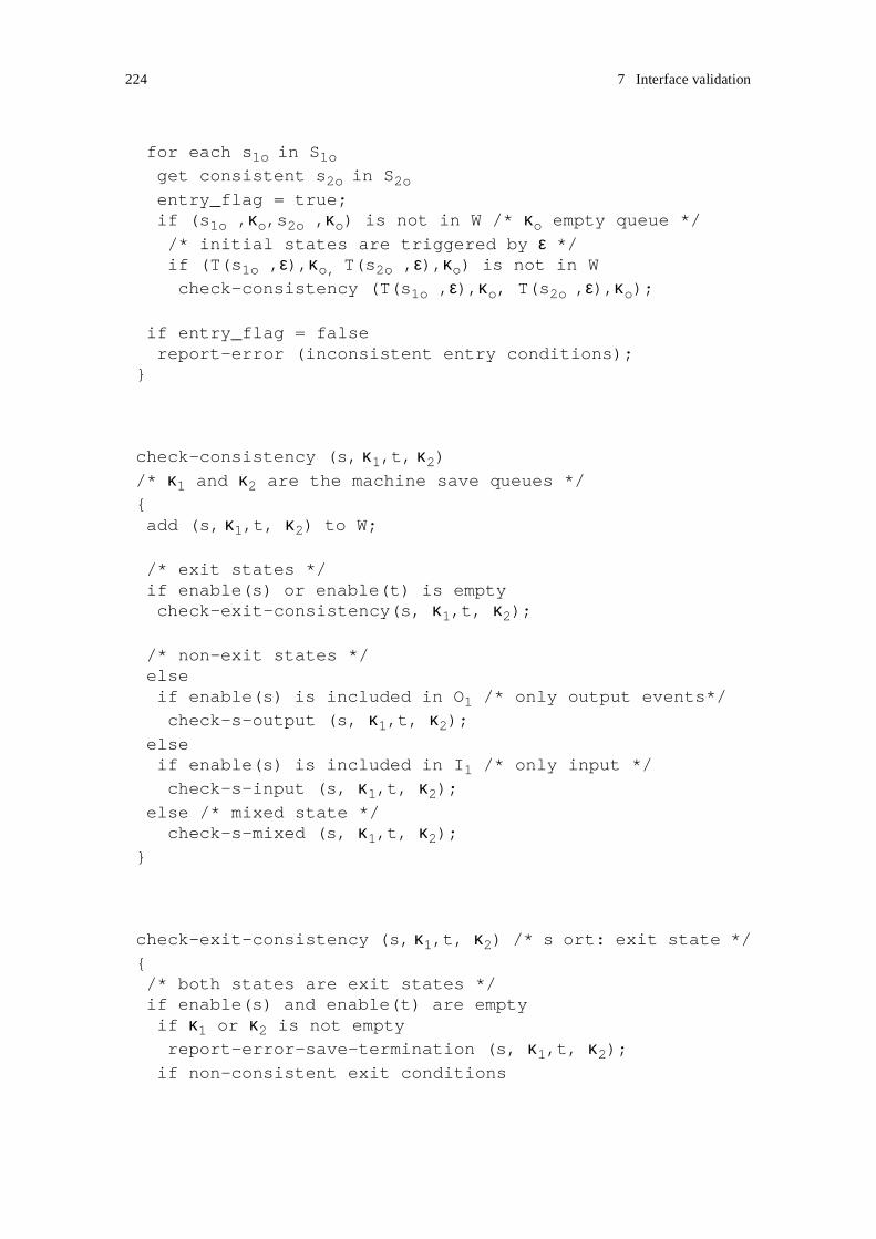
224 7 Interface validation
for each s1o in S1oget consistent s2o in S2o
entry_flag = true;if (s1o ,κo,s2o ,κo) is not in W /* κo empty queue *//* initial states are triggered by ε */if (T(s1o ,ε),κo, T(s2o ,ε),κo) is not in Wcheck-consistency (T(s1o ,ε),κo, T(s2o ,ε),κo);
if entry_flag = falsereport-error (inconsistent entry conditions);
}
check-consistency (s, κ1,t, κ2)/* κ1 and κ2 are the machine save queues */{add (s, κ1,t, κ2) to W;
/* exit states */if enable(s) or enable(t) is emptycheck-exit-consistency(s, κ1,t, κ2);
/* non-exit states */elseif enable(s) is included in O1 /* only output events*/
check-s-output (s, κ1,t, κ2);elseif enable(s) is included in I1 /* only input */
check-s-input (s, κ1,t, κ2);else /* mixed state */
check-s-mixed (s, κ1,t, κ2);}
check-exit-consistency (s, κ1,t, κ2) /* s ort: exit state */{/* both states are exit states */if enable(s) and enable(t) are emptyif κ1 or κ2 is not emptyreport-error-save-termination (s, κ1,t, κ2);
if non-consistent exit conditions

7.2 Consistency checking 225
report-error-inconsistent-termination(s, κ1,t, κ2);
/* s. not an exit state */else if enable(s) is not empty/* s sends to exit state t */if output-enable(s) is not emptyreport-error-inconsistent-termination (s,κ1,t,κ2);else/* retrieve signals from save queue */if κ1 is not emptyif some event e in κ1 belongs to input-enable (s)nκ1 = get (κ1, e);if (T(s, e), nκ1, t, κ2) is not in Wcheck-consistency (T(s, e), nκ1, t, κ2);
elsereport-error-save-termination (s, κ1,t,κ2);
/* t: not an exit state */else if enable(t) is not empty/* t sends to exit state s */
if output-enable(t) is not emptyreport-error-inconsistent-termination(s,κ1,t, κ2);else/* retrieve signals from save queue */if κ2 is not emptyif some event e in κ2 belongs to input-enable (t)nκ2 = get (κ2, e);if (s, κ1, T(s, e), nκ2) is not in Wcheck-consistency (s, κ1, T(s, e), nκ2);
elsereport-error-save-termination (s,κ1,t,κ2);
}
check-s-output (s,κ1,t,κ2) /* s: only output events */{/* s: check save consistency */if κ1 is not emptyif some event e in κ1 does not belong to save(s)report-save-inconsistency (s,κ1);

226 7 Interface validation
/* t defines only output */if enable(t) is included in O2
/* t: check save consistency */if κ2 is not emptyif some event e in κ2 does not belong to save(t)report-save-inconsistency (t,κ2);
/* t: signals sent by s can be saved */for each e in output-enable(s)if e belong to save(t)nκ2 = add (κ2, e);if (T(s, e), κ1, t, nκ2) is not in Wcheck-consistency (T(s, e), κ1, t, nκ2);
elsereport-inconsistent-state (T(s, e), κ1, t, nκ2);
/* s: signals sent by t can be saved */for each e in output-enable(t)if e belong to save(s)nκ1 = add (κ1, e);if (s, nκ1, T(t, e), κ2) is not in Wcheck-consistency (s, nκ1, T(t, e), κ2);
elsereport-inconsistent-state (s, nκ1, T(t, e), κ2);
/* t defines only input */else if enable(t) is included in I2/* retrieve saved signal if any */if some event e in κ2 belongs to input-enable(t)nκ2 = get (κ2, e);if (s, κ1, T(t, e), nκ2) is not in Wcheck-consistency (s, κ1, T(t, e), nκ2);
/* no saved signal retreived */else/* no containment */if enable(s) is not includedin union ( enable(t), save (t) )report-inconsistent-state (s, κ1,t, κ2);
for each e in enable(s)if e belongs to enable(t)if (T(s, e), κ1, T(t, e), κ2) is not in W

7.2 Consistency checking 227
check-consistency (T(s, e), κ1, T(t, e), κ2);if e belongs to save(t)nκ2 = add (κ2, e);if (T(s, e), κ1, t, nκ2) is not in Wcheck-consistency (T(s, e), κ1, t, nκ2);
/* t is a mixed state */else/* should not happen as s is not able to handle
the crossing of signals.*/report-inconsistent-state (s,κ1,t,κ2);
}
check-s-input (s,κ1,t,κ2) /* s: only input events */{/* t defines only input */if enable (t) is included in I2
/* check for deadlock */if κ1 and κ2 are empty report-inconsistent-state (s, κ1, t, κ2);
/* retrieve saved signal if any */elseif no event e in κ1 belongs to input-enable (s) and
no event e in κ2 belongs to input-enable (t)report-inconsistent-state (s, κ1, t, κ2);
if some event e in κ1 belongs to input-enable (s)nκ1 = get (κ1, e);if (T(s, e), nκ1,t, κ2) is not in Wcheck-consistency (T(s, e), nκ1,t, κ2);
if some event e in κ2 belongs to input-enable (t)nκ2 = get (κ2, e);if (s, κ1, T(t, e), nκ2) is not in Wcheck-consistency (s, κ1, T(t, e), nκ2);

228 7 Interface validation
/* t defines only output */else if enable (t) is included in O2
if κ2 is not emptyif some event e in κ2 does not belong to save(t)report-save-inconsistency (t, κ2);
/* s: retrieve saved signal if any */if some event e in κ1 belongs to input-enable (s)nκ1 = get (κ1, e);if (T(s, e), nκ1, t, κ2) is not in Wcheck-consistency (T(s, e), nκ1, t, κ2);
/* s: no saved signal retreived */else/* no containment */if output-enable (t) is not included
in union ( enable(s), save (s) )report-inconsistent-state (s, κ1, t, κ2);
/* s: signals sent by t are consumed or saved */for each e in output-enable (t)if e belongs to enable(s)if (T(s, e), κ1, T(t, e), κ2) is not in Wcheck-consistency (T(s, e), κ1, T(t, e), κ2);
if e belongs to save(s)nκ1 = add (κ1, e);if (s, nκ1, T(t, e), κ2) is not in Wcheck-consistency (s, nκ1, T(t, e), κ2);
/* t is a mixed state */else
/* s: retrieve saved signal if any */if some event e in κ1 belongs to input-enable (s)nκ1 = get (κ1, e); /* extract signal from queue */if (T(s, e), nκ1, t, κ2) is not in Wcheck-consistency (T(s, e), nκ1, t, κ2);
/* s: no saved signal retrieved */else/* t: check re-iteration of save */if some event e in κ2 does not belong to save(t)

7.2 Consistency checking 229
report-save-inconsistency (t, κ2);
/* no containment */if output-enable (t) is not includedin union ( enable(s), save (s) )report-inconsistent-state (s, κ1, t, κ2);
for each e in output-enable (t)if e belongs to enable(s)if (T(s, e), κ1, T(t, e), κ2) is not in Wcheck-consistency (T(s, e), κ1, T(t, e), κ2);
if e belongs to save(s)nκ1 = add (κ1, e);if (s, nκ1, T(t, e), κ2) is not in Wcheck-consistency (s, nκ1, T(t, e), κ2);
}
check-s-mixed (s,κ1,t,κ2) /* s: mixed initiative state */{/* check re-iteration of save */if κ1 is not emptyif some event e in κ1 does not belong to save(s)report-save-inconsistency (s, κ1);
/* t defines only input */if enable (t) is included in I2
/* t: retrieve saved signal if any */if some event e in κ2 belongs to input-enable (t)nκ2 = get (κ2, e);if (s, κ1, T(t, e), nκ2) is not in Wcheck-consistency (s, κ1, T(t, e), nκ2);
/* t: no saved signal retreived */else/* no containment */if output-enable (s) is not included in enable(t)report-inconsistent-state (s, κ1, t, κ2);
for each e in output-enable (s)if e belongs to enable(t)if (T(s, e), κ1, T(t, e), κ2) is not in W
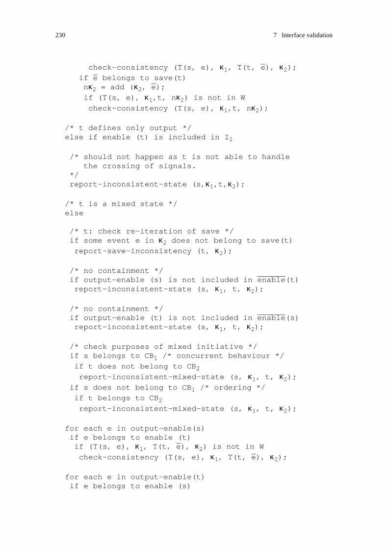
230 7 Interface validation
check-consistency (T(s, e), κ1, T(t, e), κ2);if e belongs to save(t)nκ2 = add (κ2, e);if (T(s, e), κ1,t, nκ2) is not in Wcheck-consistency (T(s, e), κ1,t, nκ2);
/* t defines only output */else if enable (t) is included in I2
/* should not happen as t is not able to handlethe crossing of signals.
*/report-inconsistent-state (s,κ1,t,κ2);
/* t is a mixed state */else
/* t: check re-iteration of save */if some event e in κ2 does not belong to save(t)report-save-inconsistency (t, κ2);
/* no containment */if output-enable (s) is not included in enable(t)report-inconsistent-state (s, κ1, t, κ2);
/* no containment */if output-enable (t) is not included in enable(s)report-inconsistent-state (s, κ1, t, κ2);
/* check purposes of mixed initiative */ if s belongs to CB1 /* concurrent behaviour */
if t does not belong to CB2
report-inconsistent-mixed-state (s, κ1, t, κ2);if s does not belong to CB1 /* ordering */
if t belongs to CB2
report-inconsistent-mixed-state (s, κ1, t, κ2);
for each e in output-enable(s)if e belongs to enable (t)if (T(s, e), κ1, T(t, e), κ2) is not in Wcheck-consistency (T(s, e), κ1, T(t, e), κ2);
for each e in output-enable(t)if e belongs to enable (s)

7.2 Consistency checking 231
if (T(s, e), κ1, T(t, e), κ2) is not in Wcheck-consistency (T(s, e), κ1, T(t, e), κ2);
/* check conflict resolution */if s belongs to CB1 and t belongs to CB2
for each e in output-enable(s)for each f in output-enable(t)if e belongs to enable (t) and f belongs to enable (s)
if ( T(T(s, e),f), κ1, T(T(t,f),e), κ2) is not in W
check-consistency ( T(T(s, e),f), κ1, T(T(t,f),e), κ2);}
7.2.4.3 Working space size
The introduction of the save feature prevents us from using a simple technique like mir-
roring for consistency checking. At the first glance, Algorithm 7.9 may appear complex.
However, even though several different cases have to be considered, the working set gen-
erated by the algorithm, i.e. the set of tuples of states and associated save queues, remains
small. As opposed to algorithms used for the generation of global state graphs in reacha-
bility analysis, our algorithm does not require a large working space.
Recall that the main problem to be addressed in reachability analysis is that of state space
explosion problem. The complexity of global state graph grows rapidly with the number
of states of the constituting state machines. The number of states is often too large for
exhaustive analysis. Consider the following example inspired from [Holzman 1991]:
- A protocol is implemented by two state machines having each 100 states and 1 message
queue. The queues are restricted to 5 slots each, and the number of messages exchanged
is 10. Each process can be in 102 different states, so the two processes can be in 104 states.
Each queue may hold between 0 and 5 messages, where each message is 1 out of 10. The
total number of states in the worst case is
104 . ( Σi=0,5 10i )2
In the worst case, the number of states is in the order of 1014 different states. Hopefully
the number of effectively reachable states is much smaller than this worst-case number.
But still it remains high for small protocols, from 105 to 109 according to [Holzman 1991].

232 7 Interface validation
In our approach, the number of states in the machines to be analysed is normally low:
• The analysis is performed on projection of s-roles, not on s-roles. In the case where an
s-role is involved in 3 associations, we may assume that 1/3rd of the s-role states are
dedicated to the interaction on each association. Thus, the number of states in each pro-
jection is approximately 1/3rd of the number of states in the s-role.
• The analysis is performed on elementary s-roles, e.g. the phases of a protocol. In the
case an s-role is composed of three elementary s-roles, the number of states of each ele-
mentary s-role is approximately 1/3rd of the number of states in the composite s-role.
The number of states in each machine to be analysed is then approximately be reduced
with a factor of about 10, and in the global state space with a factor of 102.
The number of states in the global state space can be reduced even more when the size of
the message queue is decreased. This is possible in our approach where Algorithm 7.9
does not make use of a message queue, but of a save queue. The design rules "Mixed ini-
tiative and signal sending sequences" and "Input/output event orderings and event
sequence length" contribute to simplifying the analysis:
• Following the rules related to mixed initiatives states, each machine is designed input
consistently, and the potential combinations of signal crossing are also kept low. The
purposes of the mixed initiatives are clearly identified, and conflict resolution, if any,
handled. This enables us to check each branch following a mixed initiative state against
a single branch in the complementary graph. No message queue is needed to perform
the analysis.
As the analysis restricts to one association, the number of signals in the save queue nor-
mally remains low. The design rules related to event ordering also contribute to limit the
number of slots in the save queue. We may reduce this number to 2, and then reduce the
total number of states in the worst case with a factor of 106.
Following these two reductions, the number of states in the global space in the worst case
is in the order of 106 different states instead of 1014. The number of effectively reachable
states is in fact much smaller. Both merging and the design rules related to mixed initia-
tives states contribute to that reduction:
• As explained above, each branch following a mixed initiative state is checked against

7.3 Accuracy of the validation results 233
a single branch in the complementary graph
• As the machines are merged before Algorithm 7.9 is applied, the machines do not con-
tain any equivoque transitions. A branch in the graph that would be checked against
several branches in the complementary graph before merging, can be checked against
a single branch after merging.
As every branch in one state graph can be checked against a single branch in the comple-
mentary graph, we have not to consider the product of states of the two machines. If each
machine can be in 10 different states, the two can be in 20 different states. The introduc-
tion of the save queue of 2 slots increases the number of states in the global space with a
factor of 104. As the design rules "Save and ordering" and "Ordering with save and con-
currency" constrain the use of save, signals are normally saved in a few states of the graph
reducing even more the number of states in the global space. Actually, the save queue of
2 slots is a generous assumption. One slot should hold in most cases.
7.3 Accuracy of the validation results
A main advantage of the approach is that the techniques that are proposed, can be easily
understood. However, although these techniques are simple, they enable us to identify
several anomalous behaviours. Simplification is achieved by emphasising the details sig-
nificant for the purpose of validation of the interfaces, and hiding other details. In that
way, the designer is able to comprehend single interfaces. Simplification, however, causes
some shortcomings that are discussed in this section.
7.3.1 Overspecification
Decisions and signals on non-visible associations are hidden by projection. The projection
of an s-role may produce a non-deterministic a-role behaviour, and non-determinism may
lead to ambiguity. We fail to produce dual a-roles for a-roles that present ambiguity, and
have proposed the re-design of s-roles.
In some cases, however, decisions and signals on non-visible associations are observable
from complementary s-roles. Decisions are observable when there exist dependencies
between decisions across s-roles. Signals on non-visible associations are observable when
there exist dependencies between interactions on distinct associations.

234 7 Interface validation
An example is shown in Figure 7.43. The collaboration sequence between three s-roles
“R1”, “R2 and “R3” describes two alternative behaviours: “R1” sends either signal “X”
or “Y” to both “R2 and “R3”. In the first case, the s-role “R2” further expects the signal
“B” from “R3”. In the second case, “R2” further expects the signal “C” from “R3”. The
interactions between “R1” and “R2”, and between “R1” and “R3” are dependent, and fur-
ther govern the interaction between “R2” and “R3”.
The state machine of the s-role “R2” as seen from “R3” is also described in Figure 7.43.
By projection, the signals “X” and “Y” are hidden. Seen from “R3”, the a-role presents an
input ambiguity. According to our design rules, the s-role “R2” should be re-designed. In
any case after “A”, the s-role should be prepared to both receive “B” and “C”. Further-
more, backward consistency should be enforced, and the state “2” should be able to save
“B” and “C”. After re-design, the s-role “R2” is overspecified.
As illustrated by this example, the projection may hide dependencies between interactions
on distinct associations, and lead to overspecification of the s-role graphs. The s-role
graphs become more complex. Overspecification is however harmless with respect to
consistency. It enforces the designer to produce robust specifications.
The projection transformation can be extended so that important dependencies between s-
roles can be maintained in the a-role graph. The introduction of a new projection transfor-
mation does not require changes to be made to the other validation techniques. In the
previous example, dependencies between “X” and “B”, and “Y” and “C” can be taken into
account such that the projected a-role defines a new state “2” that can both receive “B”
and “C”. The description of a new projection transformation is left for further work.
Figure 7.43 : Dependent and consistent interactions on distinct associations.
state machine of R2 observed from R3
A
X
R1 R2 R3
X
B
alt
YY
C
1
A
2
X Y
43
B C
input ambiguity
A

7.3 Accuracy of the validation results 235
7.3.2 Second order errors
An important assumption in the validation of a-roles is that each a-role provides the
expected behaviour. We assume that spontaneous sending derived by projection from the
consumption of non-visible signals can occur. As the interactions on other associations
have been validated, we expect them to behave consistently and to not lead to any error.
The assumption is erroneous when applied on spontaneous τ-transitions, and may hide
deadlocks resulting from dependencies between s-roles. An example is shown in
Figure 7.44.
In the example on Figure 7.44, a “request-answer” pattern is applied between three s-
roles. A machine cannot proceed before a request has been answered. The interactions
between “R1”, “R2” and “R3” are inconsistent and lead to deadlock. A symptom of the
deadlock can be found in the a-role graphs, but not its cause. Seen from “R3”, the a-role
derived from the role graph of “R1” contains τ-transitions. A way to remove the τ-transi-
tion between the states “2” and “3” is to enforce backward input consistency, and apply
gathering. However, here, the request sent by “R1” should first be answered in state “2”,
before “R1” further proceeds and handles itself the request received from “R3”. Another
way to remove the τ-transition in that case is to enforce backward save consistency, and
apply weak gathering. Weak gathering only maintains the observable behaviour provided
that spontaneous transitions can occur. Here applying weak gathering would hide the
deadlock error.
Figure 7.44 : Dependent and inconsistent interactions on distinct associations.
state machine of R1 observed from R3
Request-1
R1 R2 R3
Request-3
Request-2
“request-answer”
Answer
Request
pattern
1
Request-1
Request-3
2
3
Answer-1
4
Request-3
Answer-3
backwardconsistency?

236 7 Interface validation
The projection of s-roles lead to graphs that may contain acute τ-transitions. Acute τ-tran-
sitions are symptoms of errors. Without the knowledge of the behaviour occurring on
other associations, we are not always able to handle properly the τ-transitions. Their
removal may lead to second order errors. Backward save consistency and weak gathering
should be applied with care.
7.4 Summary
In this chapter, we have proposed an approach to interface validation. The approach
encompasses a constructive method for the specification of dual interfaces, and a correc-
tive method for consistency checking.
Dual a-roles can be specified provided that initial a-roles do not present any strong input,
mixed or termination ambiguity. When a full interaction behaviour is desirable, the initial
a-roles should support input consistency. Design rules have also been proposed that
reduce the complexity of the a-role descriptions and facilitate the specification of dual
roles. The design rules are simple and can easily be enforced by the designer manually or
with some design tool support. Mirroring and merging are the main techniques proposed
for the generation of dual roles.
At consistency checking, we require the a-roles to enforce the design rules introduced in
the constructive method. No assumption about the complementary a-roles are made. In
that way, a-roles are not dependent on a particular behaviour of their complementary a-
roles, and these complementary a-roles may easily be changed. The introduction of the
save feature forces us to introduce a consistency checking algorithm that is cognate to the
algorithms used for the generation of global state graphs. However our algorithm differs
from those algorithms in that it does not use any message queue, but a save queue. Both
merging and the design rules applied on s-roles and a-roles contribute to simplify the anal-
ysis and to maintain the number of states in the global state low.
The proposed validation approach has the following properties:
• Ambiguous and conflicting behaviours that lead to errors can be identified at design
time, before the validation analysis itself. The design rules enable the designer to
develop well-formed state machines.
• Validation is performed on state machine types - not instances. In that way, it can be
applied to the analysis of systems bound at run-time, and suits the needs of composi-

7.4 Summary 237
tional systems.
• The removal of acute τ-transitions simplifies the analysis, and also enables the designer
to comprehend single interfaces.
• When a component is replaced or added in a system, the analysis restrict to the com-
ponents of the system that interact with that new component. Other parts of the system
are not affected.
• Modifications of the s-role that only have impact on one interface, do not require the
analysis to be repeated on all interfaces, but only to the modified interface.
While using projections simplify the validation analysis, it may lead to overspecification.
The identification of second order errors requires more knowledge than what is described
by the specification of single interfaces.

238 7 Interface validation

- 239 -
8
Composition validation
The purpose of composition validation is to ensure that service roles are consistently com-
posed across actors. While Chapter 7 has addressed the validation of elementary s-roles,
this chapter addresses the validation of composite s-roles. Assuming that the s-roles being
composed interact consistently, we discuss how composition can be applied across actors
so that the composite s-roles also interact consistently.
As the sequential composition of s-roles is modelled using identical mechanisms as the
modelling of elementary s-roles, the techniques developed for the validation of elemen-
tary s-roles apply to s-roles composed sequentially. Concurrent composition introduces
new associations that are validated separately, also using the techniques of interface vali-
dation. The dynamic creation of s-roles requires new techniques.
8.1 Sequential collaboration composition
In this section, we assume that the identical form of composition, sequential composition,
is applied to the elementary s-roles in the interacting actors. In that case we say that the
elementary collaborations the actors contribute to, are composed sequentially. We first
discuss basic sequential composition. Then complexity is added by introducing guards,
choices and disabling.
As illustrated in Figure 8.1, different patterns of sequential collaboration composition
may be introduced depending on whether the actors involved in the composite collabora-
tion participate in any of the collaborations being composed or not. The notation
introduced in Chapter 2 is used to represent actors, s-roles and a-roles. In addition,
sequential composition is represented by an arrow that indicates the order of execution.
In case (a) of Figure 8.1, the composite collaboration consists of two collaborations com-
posed sequentially. The two collaborations involve the same three actors that respectively

240 8 Composition validation
first play the s-roles “A”, “B” and “C”, then the s-roles “D”, “E” and “F”. Case (b) differs
from (a) in that one of the actors is not involved in the first phase of the composite collab-
oration. Case (c) is a variant of case (b). It illustrates that an actor may be involved at
different phases of a composite collaboration.
In a similar way as for interface validation, we consider the composite s-roles from the
different associations they interact on. In that way, we also reason on projections at the
composite level. In case (a) of Figure 8.1, the transition from “B” to “E” will be observed
from two viewpoints: from the actor playing the composite s-role “A” followed by “D”,
and from the actor playing “C” followed by “F”.
We assume that the s-roles contributing to the elementary collaborations interact consist-
ently. In case (a) of Figure 8.1, “A” and “B” interact consistently as well as “B” and “C”.
So do their successors “D” and “E”, and “E” and “F”. According to interface validation,
we know that elementary s-roles execute consistently until they terminate, provided that
they start executing in a coordinated way. Inconsistency will then be introduced by com-
position if some transition from an s-role to its successor leads to a non-coordinated start
of execution of the s-roles. Two kinds of non-coordinated start may be happen:
• Interacting s-roles are entered through non-consistent entry conditions.
• Interacting s-roles do not start executing simultaneously. In that case, a signal may be
sent to a complementary s-role that has not yet started, leading to unspecified signal
reception.
We first discuss the second case, i.e. “non-simultaneous start”. The case of “non-consist-
ent entry conditions” is especially of interest in a composition with choice, where the
instantiation of an s-role may depend on some condition. This case is discussed in
Section 8.1.4.
Figure 8.1 : Sequential collaboration composition.
A
D
B
E
C
F
A
D
B
E F
A
D
B
E
C
G H F(a) (b)
(c)

8.1 Sequential collaboration composition 241
8.1.1 Non-simultaneous execution start
As s-roles are composed sequentially, s-roles start execution when their predecessors ter-
minate. Thus non-simultaneous execution start occurs when the predecessor s-roles, if
any, do not terminate simultaneously. In Figure 8.2, the s-role “B” continues to interact
with “A” after the interaction between “B” and “C” has terminated. Seen from “C”, this
is a termination occurrence ambiguity. In that case, the s-role “C” and its successor “F”
are not able to observe the termination of “B”.
Cases of non-simultaneous execution start also occur when the interacting actors are
involved in different phases of the composite collaboration. An s-role may not have any
predecessor, or its predecessor may not be involved in the previous phase of in the com-
posite collaboration. Both cases are illustrated in Figure 8.1. In (b), the s-role “F” has no
predecessor, and cannot determine when the s-role “B” terminates. In (c), the predecessor
of “F” does not interact with “E”, the predecessor of “H”, and then “F” cannot determine
when “H” starts. From a projection viewpoint, “E” is hidden from the composite s-role
“C” followed by “F”.
The problem of unspecified signal reception caused by non-simultaneous execution start
can be handled in two ways:
• Constraints may be set on the composition of s-roles. S-roles should be composed so
that no signal is sent to an s-role that has not yet started. An s-role that cannot observe
the termination of the predecessor of its complementary s-role should not take the ini-
tiative to send a signal. We refer to this approach using the term “constraint based
approach” throughout this section.
• Signals that may be received before the start of execution of an s-role should be han-
Figure 8.2 : Sequential composition and termination occurrence ambiguity.
x
termination of “B” seen from “C”τ
CA B
FD E
(termination occurrence ambiguity)
x
N
termination of “B” seen from “A”
“F” cannot observe thetermination of “B”

242 8 Composition validation
dled at the enclosing composite s-role level. The signals should be saved so that they
can be retrieved from the input port when the s-role the signal is addressed to, starts.
We refer to this approach using the term “save based approach” throughout this section.
Figure 8.3 and Figure 8.4 present some cases of composition and give an introduction to
the constraints of composition1. The composite s-role, “A” followed by “D”, and the ter-
mination of “A” and the start of “D” are expanded.
In Figure 8.3, the projection of “A” does not present any termination occurrence ambigu-
ity. A complementary a-role can then observe the termination of “A” and the start of
execution of “D”. A complementary a-role may then take the initiative to send to “A”. The
composition shown in case (a) is consistent. In case (b) however, we cannot determine if
the composition is applied consistently without considering the termination of the com-
plementary of “A”.
In Figure 8.4, the projection of “A” presents a termination occurrence ambiguity. The case
(a) shows a symptom of error. As a complementary a-role cannot determine the start of
execution of “D”, it should not send any signal. In case (b), similarly to the previous fig-
ure, the termination of the complementary of “A” needs to be considered.
Note that the transition between “A” and “D” in those figures occurs at once (before any
signal is retrieved in the input port) when “A” has terminated. This behaviour differs from
1. In the figures of this chapter, the modelling convention proposed for s-roles in Chapter 3 is followed: all references to s- roles are shown as instances of composite state types.
Figure 8.3 : Constraints and sequential composition (1).
x
N
D:rD
A:rA
M
z
σ−0
x
N
D:rD
A:rA
M
z
σ−0
(a) (b)
no termination occurrence ambiguity
the complementary s-role of “A”the complementary s-roleshould not present any
termination occurrence ambiguitycan take
the initiative to send

8.1 Sequential collaboration composition 243
a spontaneous transition behaviour (τ-transition) where signals may be retrieved from the
input port before the spontaneous transition is triggered.
The graph of the composite s-role remains simple when a constraint based approach is
used. It is not necessary to specify any information related to the interaction of the ele-
mentary s-roles at the composite level. However this solution is not always applicable. It
requires that at least one of the interacting s-roles is able to observe the start of its com-
plementary. Otherwise none of them is enabled to send and a deadlock occurs. An
example is shown in Figure 8.5. Neither “B” nor “C” can observe the termination of each
other. Thus neither “E” nor “F” should take the initiative to send to each other.
Another drawback of a constraint based approach is that it prevents us from designing ele-
mentary s-roles independently from the s-roles they are composed with, and the way they
are composed. Ideally no assumption should be made about the context of execution start,
Figure 8.4 : Constraints and sequential composition (2).
D:rD
A:rA
M
z
σ−0
x
D:rD
A:rA
M
z
σ−0
(a) (b)
termination occurrence ambiguity
symptom of error
τ
x
τ
the complementary s-role of “A”should not present any
termination occurrence ambiguity
Figure 8.5 : Sequential composition and deadlock.
x
τ
CA B
FE
x
N
G
y
M
y
τ
should not start sending to “E”
should not start sending to “F”

244 8 Composition validation
because assumptions make service adaptation difficult. A change in an s-role that influ-
ences the observation of its termination on one association, should not have impact on the
design of the successor s-roles, or on the design of the complementary s-roles on that
association.
Contrary to the constraint based approach, the save based approach introduces some com-
plexity in the graph of the composite s-roles, but service adaptation remains flexible.
Figure 8.6 presents an example where signal reception is handled at the composite level.
Here the occurrence of the termination of “A” cannot be observed by a complementary s-
role. In order to ensure that no signal sent to “D” is received and discarded before the start
of “D”, the signals received in the initial state of “D”, here “M”, are saved at the composite
level in the state before “D”.
This approach using save is a kind of backward save consistency (see Section 7.1.4.1.2).
The occurrence of the termination of “A” is not observable, and the transitions between
the end of interaction with “A” and the start of the s-role “D” is a non-visible behaviour.
By specifying save, backward save consistency is enforced at the composite level.
Another form of non-visible behaviour is introduced when an elementary s-role is not
observable by the complementary composite s-role. In that case, save can also be used to
enforce backward consistency at the composite level. Two examples are shown in
Figure 8.7. The s-role “E” is not observable from the composite s-role that sends “M” to
“H”. The sender of “M” then cannot observe the start of “H”. In order to ensure that the
signal is not received and discarded before the start of “H”, the signal is saved at the com-
posite level. In case (a), the termination of “B” is observable, and the signal “M” needs
Figure 8.6 : Save and sequential composition.
D:rD
A:rA
M
z
σ−0
M
add save “M”
x
non-visible transition
τ
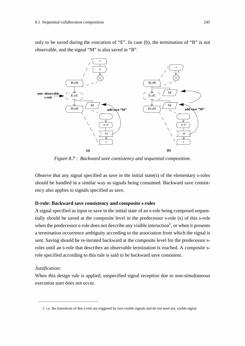
8.1 Sequential collaboration composition 245
only to be saved during the execution of “E”. In case (b), the termination of “B” is not
observable, and the signal “M” is also saved in “B”.
Observe that any signal specified as save in the initial state(s) of the elementary s-roles
should be handled in a similar way as signals being consumed. Backward save consist-
ency also applies to signals specified as save.
D-rule: Backward save consistency and composite s-roles
A signal specified as input or save in the initial state of an s-role being composed sequen-
tially should be saved at the composite level in the predecessor s-role (s) of this s-role
when the predecessor s-role does not describe any visible interaction1, or when it presents
a termination occurrence ambiguity according to the association from which the signal is
sent. Saving should be re-iterated backward at the composite level for the predecessor s-
roles until an s-role that describes an observable termination is reached. A composite s-
role specified according to this rule is said to be backward save consistent.
Justification:
When this design rule is applied, unspecified signal reception due to non-simultaneous
execution start does not occur.
1. i.e. the transitions of this s-role are triggered by non-visible signals and do not send any visible signal.
Figure 8.7 : Backward save consistency and sequential composition.
H:rH
E:rE
M
z
σ−0
Madd save “M”
B:rB
M
x
τ
H:rH
E:rE
M
z
σ−0
Madd save “M”
B:rB
non- observables-role
x
N
(a) (b)

246 8 Composition validation
The rule applies locally on the composite s-role. No assumption about the termination of
the complementary elementary s-roles needs to be done. For example, in case (b) of
Figure 8.3 on page 242, the role “D” can send a signal without taking into account whether
the predecessor of its complementary presents a termination occurrence ambiguity or not.
Furthermore, extensions of the complementary s-role that modify the occurrence of ter-
mination, have no impact on the design of “D”.
A designer may prefer to redesign the elementary s-roles and the composite s-role so that
no termination occurrence ambiguity and no non-observable s-role behaviour occur
before the reception of a signal in a starting s-role. Redesign along these lines is not
always possible. Backward save consistency is.
In the following, we assume that composite s-roles are designed according to the design
rule "Backward save consistency and composite s-roles".
8.1.2 Implicit and explicit triggering
Recall that three patterns of s-roles assignment or triggering have been introduced in
Chapter 3. These triggering patterns are also shown in Figure 8.8:
• Spontaneous triggering: an s-role is instantiated as part of a logical sequence of actions
of an actor.
• Implicit triggering: triggering is requested by another actor, and expressed by a stimu-
lus defined as part of the collaboration to be started and of the s-role to be assigned.
• Explicit triggering: triggering is requested by another actor, and expressed by a stimu-
lus defined explicitly for triggering purposes. This stimulus specifies the s-role to be
played.
The results of Section 8.1.1 restrict to the first form of triggering. In this section, we
extend these results to implicit and explicit triggering. Although these triggering patterns
usually apply in the case of sequential composition with choice (see Section 8.1.6), we
first consider them in basic sequential composition.
Again, we assume that the elementary s-roles interact consistently. Inconsistency can then
be introduced in the transition between s-roles. If we assume that s-roles are composed
sequentially with no disabling (see Section 8.1.7), a predecessor s-role in a sequence

8.1 Sequential collaboration composition 247
should terminate before its successor is triggered. The triggering signal should not force
the termination of the predecessor s-role, i.e the triggering signal should not be consumed
before the predecessor s-role has terminated its execution. In the case the sender of the
triggering signal cannot observe the termination of the predecessor, backward save con-
sistency should be enforced. As the input and save of a signal cannot be both specified in
a state, we propose to insert a new non-composite state at the composite level that handles
the reception of the triggering signal. Two examples are shown in Figure 8.9. The projec-
tion of the termination of “A” is considered from the association where “M” is sent in case
(a), and from the association where “Play” is sent in case (b).
Figure 8.8 : S-role triggering patterns.
D:rD
A:rA
(a) spontaneous triggering D:rD
A:rA
(b) implicit triggering
D:rD
A:rA
(c) explicit triggering
M
via M
Play (D)
role
M
z
σ−0
M
Figure 8.9 : Triggering and termination occurrence ambiguity.
M
add save “M”
x
τ
D:rD
A:rA
(a) implicit triggering
M
via M
M
z
σ−0
M
idleadd new state
D:rD
A:rA
(b) explicit triggering
Play (D)
role
x
τ
Playidleadd new state

248 8 Composition validation
D-rule: Triggering and consistency
A non-composite state that handles the reception of the implicit or explicit triggering sig-
nal should be inserted in the composite s-role graph between the triggered s-role and its
predecessor, when the predecessor s-role does not describe any visible interaction1, or
when it presents a termination occurrence ambiguity according to the association from
which the triggering signals are sent. The saving of triggering signals should be re-iterated
backward at the composite level for the predecessor s-roles until an s-role that describes
an observable termination is reached.
This design rule describes an extended backward save consistency. It ensures that signals
are saved as in backward save consistency, but also that they do not force termination.
In the following, we assume that composite s-roles are designed according to the design
rule "Triggering and consistency".
Note that when implicit triggering is used, the triggered s-role is entered through an entry
point. The operations performed in the composite s-role graph on the consumption of the
triggering signal should be consistent with the operations that are performed when the
triggering signal is consumed after entering the elementary s-role.
8.1.3 Granularity
In the previous examples, the same s-role granularity is enforced across actors, i.e. an s-
role in one actor interacts with a single s-role in another actor. This assumption on similar
granularity is acceptable as we have proposed to consider services and service features as
collaborations between roles. A role is justified by a collaboration.
The kind of collaboration pattern shown in Figure 8.10, or more complex patterns, are left
to further work. In Figure 8.10, we may choose to expand the composite s-role “B fol-
lowed by C”, or consider two distinct associations from “A” to “B” and from “A” to “C”.
In the following, we assume that the same s-role granularity is enforced across actors.
1. i.e. the transitions of this s-role are triggered by non-visible signals and do not send any visible signal.

8.1 Sequential collaboration composition 249
8.1.4 Checking entry consistency
Inconsistency may be introduced when interacting s-roles are entered through non-con-
sistent entry conditions. This section gives guidelines for checking the consistency of
entry conditions.
During interface validation, consistent entries between interacting a-roles have been iden-
tified. The entries that have no matching consistent entries in the complementary graph(s)
are also marked. These marked entries should never be used in spontaneous or explicit
triggering.
When interacting s-roles are triggered spontaneously or explicitly, we simply verify that
the entry conditions of s-roles are consistent. Recall the extension introduced in SDL that
enables us to express entry conditions as OR-logical expressions (Section 6.3.3.1.1 on
page 121). Using that extension, the expression “c1 or c2” is allowed, and consistent with
“c1”. The default entry covers any condition except those explicitly defined in the s-role.
Thus the default entry in one s-role may be consistent with the named entry condition of
an other s-role.
When implicit triggering is used, the triggered s-role should always be entered through an
entry condition that refers to the point that follows the reception of this signal in the s-role
graph. It is not that entry condition which is used when checking the consistency of the
entry conditions between interacting s-role; it is the entry condition attached to the ele-
mentary s-role before the reception of the triggering signal that is used. For example, in
Figure 8.9 (a), it is not the entry condition “M” that is used, but the default entry condition
in the graph, as the default entry precedes the reception of the triggering signal “M”.
Figure 8.10 : S-role granularity across actors.
B
A
C

250 8 Composition validation
8.1.5 Guards
Guards have been proposed in Section 4.1.1 that prefix (or guard) the transition to a new
s-role. Again, inconsistency may be introduced in the transition between s-roles. Several
kinds of errors may occur:
• The guard forces the predecessor s-role to terminate before it has reached an exit node.
To avoid such improper termination (seen from the analysis point of view), a non-com-
posite state should be inserted in the graph of the composite s-role before the guard is
specified. In Figure 8.11, the non-composite state “idle” is inserted before the guard.
• A complementary s-role takes the initiative to send before the guard becomes true. This
may happen when the condition expressed by the guard is not taken into account by the
complementary s-role or is non-observable from this s-role. It can be avoided by apply-
ing backward save consistency as illustrated in Figure 8.12.
• The guard never becomes true.The value of a guard may depend on operations that
have already occurred in the collaboration, on operations being performed by the inter-
acting s-roles that have not yet terminated, or on operations performed in
Figure 8.11 : Termination and guarded sequential composition.
condmay force the
D:rD
A:rA
premature termination of Acond
insert a
D:rD
A:rA
idlenon-composite state
Figure 8.12 : Backward save consistency and guarded sequential composition.
condnon-observable
D:rD
A:rA
idle
M
z
σ−0
M
add save “M”
condition

8.1 Sequential collaboration composition 251
collaborations performing concurrently. The identification of these operations and
their tracing during interaction may be complex. Techniques for the abstraction of var-
iables that contribute to the simplification of the analysis are proposed in [Boroday and
al. 2002]. In our approach we do not further elaborate on these techniques for checking
that guards behave correctly. We rather advise to restrict the use of guards to conditions
that can be easily checked. The conditions may describe a local event, e.g. the release
of a local resource, or global event, e.g. the termination of some s-role contributing to
the collaboration. In the case where complex conditions need to be expressed, we pro-
pose to use timers for the detection of deadlocks. This is illustrated by Figure 8.13.
D-rule: Guards and composite s-roles
The preconditions expressed by a guard in sequential composition should relate to local
or global conditions that can easily be checked. A non-composite state should be inserted
in the composite s-role graph between the guarded s-role and its predecessor when a pre-
condition can become true before the termination of the predecessor. Timers that enable
the detection of deadlocks should be specified in the case where the validation analysis
fails to ensure that deadlocks do not occur.
Observe that conditions that relate to the termination of an s-role are checked using the
techniques proposed for interface validation.
8.1.5.1 Synchronisation guards
Guards may be used as a mean to synchronise the transition to new s-roles across actors.
Guards are specified as continuous signals and describe global conditions. The conditions
expressed by the guards usually relate to the termination of the complementary s-roles.
This is illustrated in Figure 8.14.
Figure 8.13 : Deadlock detection in guarded sequential composition.
cond
error detection
D:rD
A:rA
idle
setguard-timer
resetguard-timer
guard-timer
Error

252 8 Composition validation
Using synchronisation guards, none of the s-roles start sending before its complementary
has started, and the specification of save in the composite graph can be avoided. Thus the
composite graph is simplified. Notice that, however, backward save consistency is still
maintained in Figure 8.14. The conditions expressed by the guards are observable from
the complementary s-roles, and can be considered as a visible interaction. Of course,
guards should not force any s-role termination, and a non-composite state should possibly
be inserted in the graph.
Avoiding save through synchronisation guards is not always possible. When a condition
expressed by a guard is not observable, using save is needed. An example is shown in
Figure 8.15. Here, “D” starts when “B” (and “A”) has (have) terminated. “D” may not
however be able to determine when “E” starts. This is the case when the s-role cannot
observe the composite s-role “C followed by F”. Using save may be required in the com-
posite s-role “B followed by E”. This is a normal case of backward save consistency.
In this example, the condition “C has terminated” may implicitly be observed when “A”
interacts with “C”, or explicitly observed when the guard in the composite s-role “A fol-
lowed by D” is extended to include the termination of “C” (i.e. the guard is specified as
“A and C have terminated”). We advise that guards explicitly describe the condition of
Figure 8.14 : Guards and synchronisation across actors.
A B
D E
B hasterminated
A hasterminated
Figure 8.15 : Non-observable conditions and synchronisation across actors.
A B
D E
B hasterminated
A and C haveterminated
C
F
B hasterminated
non-observablecondition from “A->D”

8.1 Sequential collaboration composition 253
synchronisation. This facilitates the understanding of service models, their reuse and
extension.
Synchronisation guards contribute to simplify the composite s-role graph in the case
where a few s-roles are involved in the elementary collaborations. The specification of
save in the composite graph can be avoided. When several s-roles are involved, the com-
plexity of this form of synchronisation increases. A drawback with the solution is that the
addition of new s-roles in the collaboration may require modifications to be done to
guards in several composite s-roles. In that way, the solution is not flexible enough for the
purposes of service adaptation in a dynamic context. Backward save consistency is a more
robust approach.
8.1.6 Choices
Using choice, alternative s-roles can be specified in a sequential composite s-role. Guards
and signals are used to control the selection of an s-role among alternative s-roles. The
same kinds of errors as described for basic and guarded sequential compositions may
occur, and can be avoided using identical solutions. In addition to these errors, the con-
sistency of the selection of behaviours across actors must be ensured.
Optionally, choice is applied in order to enter a single s-role through alternative entry con-
ditions. This case can be treated in a similar way as the selection of one s-role among
several s-roles.
Choice is not necessarily enforced in every actor participating into the composite collab-
oration. Two composition patterns are shown in Figure 8.16. In case (a), distinct s-roles
are chosen in every actor at the end of the first elementary collaboration. While in (b),
choice is only applied in two of the three actors. In that case, the s-role “F” should interact
consistently with both “E1” and “E2”. “E1” and “E2” may provide identical or distinct a-
roles to “F”.
Again, as in the case of basic sequential composition, we assume the s-roles contributing
to the elementary collaborations interact consistently. While in basic sequential composi-
tion it is straightforward to identify the s-roles that an s-role interact with, and to perform
the consistency checks, choice introduces some difficulty. In each actor, the composite
role is described as graph of elementary s-roles, and each elementary s-role may possibly
interact with several other elementary s-roles in each other actor. In case (a) of
Figure 8.16, the s-role “D1” may interact with the two successors of “B”, “E1” and “E2”.

254 8 Composition validation
The successors of “D1” may themselves interact with the successors of “E1” and “E2”.
Of course, we wish to reduce to number of consistency checks to be performed on ele-
mentary s-roles.
We assume that each s-role selected after a choice within an s-role interacts with a single
s-role in another actor and that the interacting s-role pairs can be easily identified. This
assumption is acceptable as s-roles belong to collaborations. It is a collaboration rather
than an s-role that is selected in a choice. Behaviour overlap between collaborations is
however possible, as described as in case (b) of Figure 8.16.
We also assume that the guards controlling the selection in choice represent abstract
states, and that the values of guards can be easily compared across actors. This means that
guards across actors should represent the same abstract states or closely related states. For
example, guards may represent global termination conditions, e.g. “success” and “fail-
ure”, in a collaboration. This assumption is acceptable as the composite s-roles link
together elementary behaviours. We do not need to express detailed information in the
graph of a composite s-role as we do in the graph of an elementary s-role.
Recall that two main mechanisms have been proposed for the selection of s-roles in a
choice:
• The selection of a behaviour is controlled by guards expressed as predicates over con-
ditions. The initiative to select an s-role in a choice is taken locally. Of course, the
conditions may relate to a global event. Conditions are represented in SDL using exit
conditions or continuous signals, as shown in Figure 8.17.
• The selection of a behaviour is triggered by a signal, as shown in Figure 8.18. The ini-
tiative to select an alternative s-role is then taken externally.
Figure 8.16 : Choice in collaboration composition.
CA B
F2D2 E2
F1D1 E1
CA B
F
D2 E2
D1 E1
(a) (b)

8.1 Sequential collaboration composition 255
Different selection mechanisms may be applied in interacting actors. An example is
shown in Figure 8.19.
As identical concepts are used to model choice and to model elementary s-roles, the same
kinds of anomalous behaviours may occur:
• The conditions that control the selection of an s-role may be non-observable from some
interacting s-role. The projection of the composite s-role on the association with that
actor contains equivoque s-role transitions, and a behaviour ambiguity may occur.
Ambiguity can be avoided when the s-roles the equivoque transitions lead to, take the
initiative to send a signal in their initial state; the s-roles should send distinct signals in
this case. When choice is applied in the interacting s-role, the selection of a behaviour
can be triggered by these signals. This approach is illustrated in Figure 8.19. Another
solution is to define signals that explicitly describe the choice (i.e. as part of a manage-
ment s-role). This solution introduces complexity in the graph of the composite s-roles,
but does not set any constraint on the modelling of s-roles.
• The signals that control the selection of an s-role are sent by distinct s-roles. The pro-
jections of the composite s-role on the two associations towards these s-roles contain
a mixed initiative state, and a conflict may occur. Input consistency should be enforced
Figure 8.17 : Choice using predicates over conditions.
(a) exit conditions
D1:rD1
A:rA
cond1D2:rD2
cond1 cond2
D1:rD1
A:rA
D2:rD2
cond2
(b) continuous signals
Figure 8.18 : Choice using triggering signals.
A:rA
D1:rD1
M1
via M1D2:rD2
M2
via M2

256 8 Composition validation
at the composite level, and conflict resolved in a similar way as in elementary s-roles.
This case illustrated in Figure 8.20 which shows a general solution to conflict resolu-
tion. Other solutions may be proposed.
D-rule: Ambiguity and composite s-roles
Ambiguity may occur when a choice made in a composite s-role is not observable by
some of the interacting s-roles. Ambiguity can be avoided by the sending of triggering
signals.
D-rule: Conflict and composite s-roles
Conflict may occur when the selection of a behaviour in a composite s-role is triggered by
Figure 8.19 : Choice: equivoque s-role transitions.
cond1
D1:rD1
A:rA
D2:rD2
cond2
M 1
z
σ−0
non-observablechoice
M 2
x
σ−0
B:rB
E1:rE1
M1
via M1E2:rE2
M2
via M2
(a) composite s-role (projection)
(b) complementary s-role
output divergence(no ambiguity)
Figure 8.20 : Choice: input consistency and conflict resolution.
A:rA
D1:rD1
M1
via M1D2:rD2
M2
via M2
D1
M2
with history
input consistency
M1
input consistency
resolve2
D2with history
resolve1
conflict detection
conflict resolution
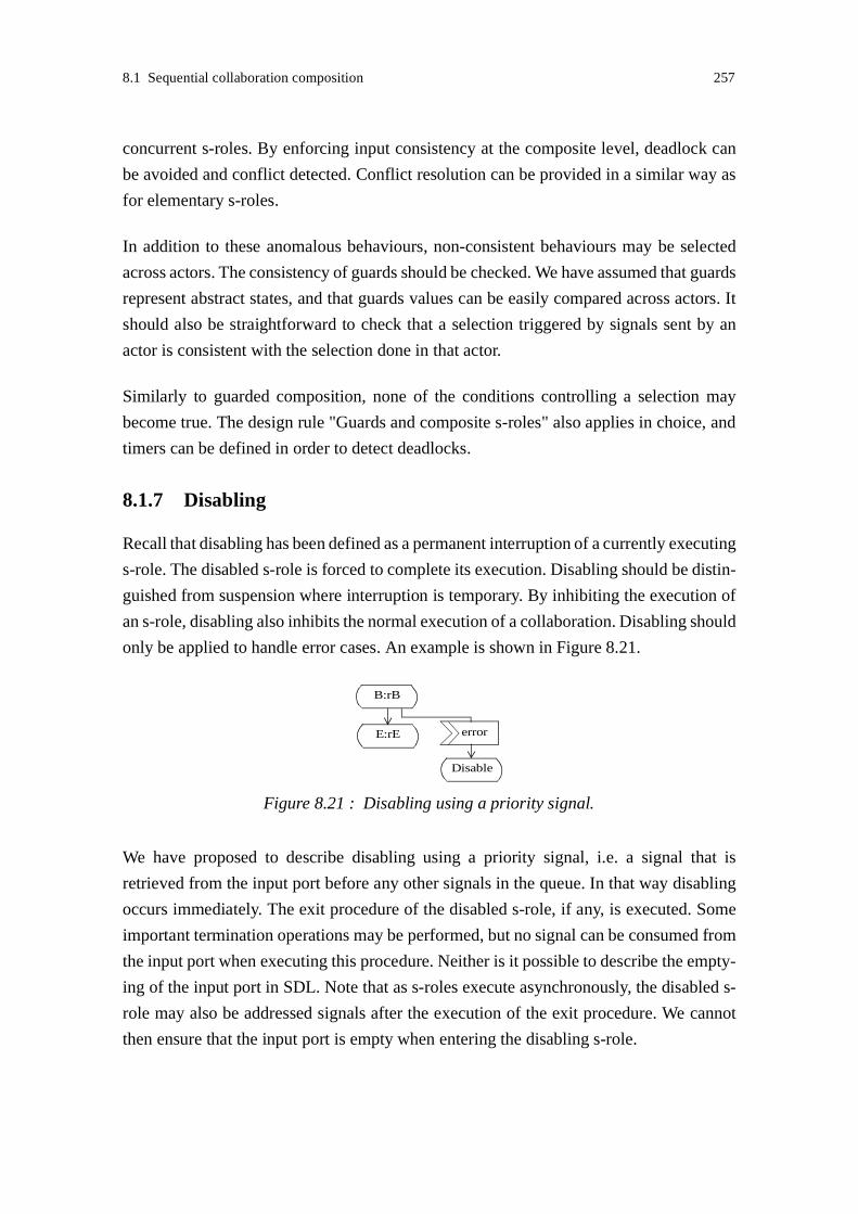
8.1 Sequential collaboration composition 257
concurrent s-roles. By enforcing input consistency at the composite level, deadlock can
be avoided and conflict detected. Conflict resolution can be provided in a similar way as
for elementary s-roles.
In addition to these anomalous behaviours, non-consistent behaviours may be selected
across actors. The consistency of guards should be checked. We have assumed that guards
represent abstract states, and that guards values can be easily compared across actors. It
should also be straightforward to check that a selection triggered by signals sent by an
actor is consistent with the selection done in that actor.
Similarly to guarded composition, none of the conditions controlling a selection may
become true. The design rule "Guards and composite s-roles" also applies in choice, and
timers can be defined in order to detect deadlocks.
8.1.7 Disabling
Recall that disabling has been defined as a permanent interruption of a currently executing
s-role. The disabled s-role is forced to complete its execution. Disabling should be distin-
guished from suspension where interruption is temporary. By inhibiting the execution of
an s-role, disabling also inhibits the normal execution of a collaboration. Disabling should
only be applied to handle error cases. An example is shown in Figure 8.21.
We have proposed to describe disabling using a priority signal, i.e. a signal that is
retrieved from the input port before any other signals in the queue. In that way disabling
occurs immediately. The exit procedure of the disabled s-role, if any, is executed. Some
important termination operations may be performed, but no signal can be consumed from
the input port when executing this procedure. Neither is it possible to describe the empty-
ing of the input port in SDL. Note that as s-roles execute asynchronously, the disabled s-
role may also be addressed signals after the execution of the exit procedure. We cannot
then ensure that the input port is empty when entering the disabling s-role.
Figure 8.21 : Disabling using a priority signal.
B:rB
errorE:rE
Disable

258 8 Composition validation
The discarding of the signals addressed to the disabled s-role1 may be handled in the dis-
abling s-role, or at the composite level. As disabling s-roles usually handle general error
cases, their behaviour should not depend on the disabled s-roles. The specification of sig-
nal discarding in the composite s-role increases the complexity of the graph of this s-role.
When discarding has occurred, the discarding of the signals addressed to the disabled state
is normally not critical. Therefore we propose, as an exception, to tolerate the consump-
tion of those signals not to be described after disabling. This is a form of inconsistency
that we tolerate.
When an s-role is disabled, it should inform the s-roles it interacts with. Usually these s-
roles will also be disabled. The termination of s-roles and release of resources should be
properly handled across actors. A collaboration that aims to handle disabling should be
described. This collaboration is critical, and its consistency should be carefully checked.
A simple collaboration pattern is proposed in Figure 8.22.
8.2 Concurrent collaboration composition
In this section, we assume the identical form of composition, concurrent composition, is
applied to the elementary s-roles in the interacting actors. In that case we say that the ele-
mentary collaborations the actors contribute to, are composed concurrently. As illustrated
in Figure 8.23, different patterns of collaboration composition may be introduced.
The concurrent s-roles may execute more or less dependently. In case (a) of Figure 8.23,
the s-roles “A” and “C” are dependent. The coordination between these s-roles is mod-
elled as an interaction on an association. On the other hand, the s-roles “B” and “D” are
independent. Case (b) is quite similar to (a). The independent s-roles “B” and “D” are
assigned to distinct actors. From a validation viewpoint, the two cases are identical in that
the interaction on each association is validated separately. In case (c), the s-role “A” inter-
1. i.e. the signals in the s-role valid input list.
Figure 8.22 : Disabling all s-roles.
Request-aDisable
A B Cmsc Disabling
Disable
Disablediscard
informassociated s-roles
do not wait foranswer to request-a

8.2 Concurrent collaboration composition 259
acts with two independent s-roles “B” and “D” that are composed concurrently. The
interactions between “A” and “B” and “A” and “D” are modelled using two distinct asso-
ciations. The interaction on each association is validated separately.
In the examples, concurrent collaboration composition introduces new associations that
are validated separately. In that way, no new mechanism is needed in the validation
analysis.
Complexity is added when the composed s-roles are dependent. Dependencies between s-
roles are illustrated in Figure 8.24. In (a), the s-roles “A” and “C” are dependent, as well
as “B” and “D”. A deadlock may be introduced when the concurrent s-roles “A” and “C”,
share some resource, the concurrent s-roles “B” and “D” also do so, and the allocation of
the resource is not coordinated across the actors. Case (b) is a simplification of (a) where
two concurrent s-roles are replaced by a single s-role.
The projection hides dependencies between interactions on distinct associations. This
may lead to overspecification of the s-role graphs, and in the worst case to second order
errors. The problem is not new. It was also a possible problem encountered by elementary
s-roles and has been discussed in Section 7.3. However the concurrent composition of s-
roles highlights the dependencies between associations. Recall that acute τ-transitions are
symptoms of errors, and their removal may lead to second order errors.
8.2.1 Dynamic s-role composition
On way to model concurrent composition is to use process agents. Dynamic s-role com-
position can then be modelled by the creation of process agents at run-time. Following the
B
D
A
Figure 8.23 : Concurrent collaboration composition (1).
A
C
B
D
(a) (b) (c)
A
C
B
D
B
D
A
Figure 8.24 : Concurrent collaboration composition (2).
A
C
B
D
(a) (b)
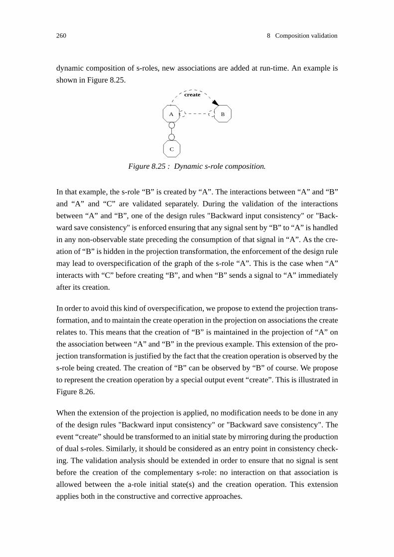
260 8 Composition validation
dynamic composition of s-roles, new associations are added at run-time. An example is
shown in Figure 8.25.
In that example, the s-role “B” is created by “A”. The interactions between “A” and “B”
and “A” and “C” are validated separately. During the validation of the interactions
between “A” and “B”, one of the design rules "Backward input consistency" or "Back-
ward save consistency" is enforced ensuring that any signal sent by “B” to “A” is handled
in any non-observable state preceding the consumption of that signal in “A”. As the cre-
ation of “B” is hidden in the projection transformation, the enforcement of the design rule
may lead to overspecification of the graph of the s-role “A”. This is the case when “A”
interacts with “C” before creating “B”, and when “B” sends a signal to “A” immediately
after its creation.
In order to avoid this kind of overspecification, we propose to extend the projection trans-
formation, and to maintain the create operation in the projection on associations the create
relates to. This means that the creation of “B” is maintained in the projection of “A” on
the association between “A” and “B” in the previous example. This extension of the pro-
jection transformation is justified by the fact that the creation operation is observed by the
s-role being created. The creation of “B” can be observed by “B” of course. We propose
to represent the creation operation by a special output event “create”. This is illustrated in
Figure 8.26.
When the extension of the projection is applied, no modification needs to be done in any
of the design rules "Backward input consistency" or "Backward save consistency". The
event “create” should be transformed to an initial state by mirroring during the production
of dual s-roles. Similarly, it should be considered as an entry point in consistency check-
ing. The validation analysis should be extended in order to ensure that no signal is sent
before the creation of the complementary s-role: no interaction on that association is
allowed between the a-role initial state(s) and the creation operation. This extension
applies both in the constructive and corrective approaches.
Figure 8.25 : Dynamic s-role composition.
A B
create
C

8.2 Concurrent collaboration composition 261
The creation example is extended in Figure 8.27 by adding an interaction between the s-
roles “B” and “C”. Here the design rule "Backward save consistency" enforces that any
signal sent by “B” to “C” is saved in any non-observable state preceding the consumption
of that signal in the s-role “C”. Again, the enforcement of the design rule may lead to over-
specification of the graph of an s-role, here “C”. In that case, the extension proposed for
the projection of create does not apply.
Overspecification is a drawback in a validation approach using projections. In order to
avoid overspecification, it is possible to extend the projection transformation so that
dependencies between visible and non-visible interfaces are highlighted and maintained
during projection. Particular events can be marked in the s-role graph and attached a par-
ticular semantics, so that they can be handled in special ways during projection. For
example, an event may be attached an s-role start semantics. Using marks should be
applied with care. Marks should be consistent with the semantics of interactions, and
should be kept consistent with the semantics of interactions when changes are introduced
in the system.
Figure 8.26 : Projection extension: adding create.
1
X
2
Y
B
1
create
2project
F
3
F
3
Figure 8.27 : Dynamic composition (2).
C
A B
create
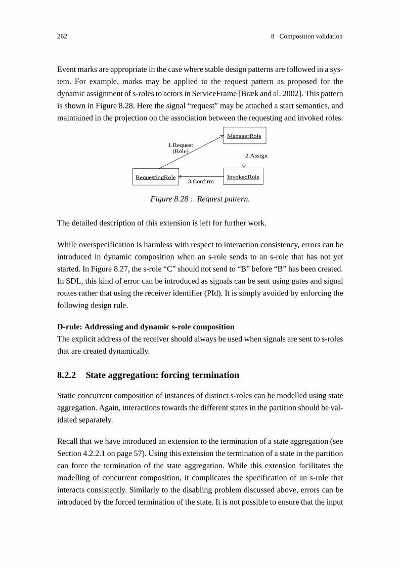
262 8 Composition validation
Event marks are appropriate in the case where stable design patterns are followed in a sys-
tem. For example, marks may be applied to the request pattern as proposed for the
dynamic assignment of s-roles to actors in ServiceFrame [Bræk and al. 2002]. This pattern
is shown in Figure 8.28. Here the signal “request” may be attached a start semantics, and
maintained in the projection on the association between the requesting and invoked roles.
The detailed description of this extension is left for further work.
While overspecification is harmless with respect to interaction consistency, errors can be
introduced in dynamic composition when an s-role sends to an s-role that has not yet
started. In Figure 8.27, the s-role “C” should not send to “B” before “B” has been created.
In SDL, this kind of error can be introduced as signals can be sent using gates and signal
routes rather that using the receiver identifier (PId). It is simply avoided by enforcing the
following design rule.
D-rule: Addressing and dynamic s-role composition
The explicit address of the receiver should always be used when signals are sent to s-roles
that are created dynamically.
8.2.2 State aggregation: forcing termination
Static concurrent composition of instances of distinct s-roles can be modelled using state
aggregation. Again, interactions towards the different states in the partition should be val-
idated separately.
Recall that we have introduced an extension to the termination of a state aggregation (see
Section 4.2.2.1 on page 57). Using this extension the termination of a state in the partition
can force the termination of the state aggregation. While this extension facilitates the
modelling of concurrent composition, it complicates the specification of an s-role that
interacts consistently. Similarly to the disabling problem discussed above, errors can be
introduced by the forced termination of the state. It is not possible to ensure that the input
Figure 8.28 : Request pattern.
1.Request
RequestingRole
ManagerRole
InvokedRole
2.Assign
3.Confirm
(Role)

8.3 Sequential and concurrent compositions 263
port of the aggregate s-role is empty when the termination takes place. The designer
should be aware of this weakness. The discarding of the signals addressed to the aggregate
s-role may be handled in the successor state or at the composite level. However the dis-
carding of the signals may also be tolerated as in the case of disabling.
8.3 Sequential and concurrent compositions
In this section, we assume that different forms of composition, sequential or concurrent
composition, can be applied within the interacting actors. This is illustrated in
Figure 8.29. Sequential composition is applied in one actor and concurrent composition
in the other actor. The concurrent s-roles may execute more or less dependently. Again,
the interactions towards the concurrent actors are validated separately. The start of execu-
tion of the s-roles should be coordinated. The techniques proposed in Section 8.1 can be
applied.
In case (a) of Figure 8.29, the s-role “D” cannot observe the termination of the predeces-
sor of “C”. Backward save consistency can be enforced in the composite s-role “A
followed by C” so that unspecified signal reception does not occur. In that case, whether
“B” and “D” are composed sequentially or concurrently does not matter.
In case (b), the s-roles “B” and “D” are dependent. The interaction between “D” and “C”
should not start before “A” has terminated. Dependencies between the interactions
between “B” and “D”, and “D” and “C” may lead to a deadlock. The ordering enforced
between “A” and “C” can be handled in a similar way as an s-role creation, i.e. as if “A”
creates “C”. The discussion of Section 8.2.1 applies here.
Again, the concurrent composition of s-roles highlights any dependencies between s-
roles. The marking of events may enhance the validation method. Dependencies between
associations that propagate through composition complicate service adaptation. They
should thus be avoided.
Figure 8.29 : Sequential and concurrent composition.
(b)
A
C
B
D
(a)
A
C
B
D

264 8 Composition validation
8.3.1 State aggregation: exit conditions
Recall that we have introduced an extension to exit points in state aggregation (see Sec-
tion 4.2.2.1 on page 57). Using this extension, an exit condition of a state aggregation can
be expressed as a logical expression of exit conditions of the states in the partition. Check-
ing the consistency of choices requires special attention if choice is based on exit
conditions. The designer should distinguish between the termination of state aggregation
and the termination of a state partition.
An example is shown in Figure 8.30. Here, in each composite role, the choice is based on
the exit condition of the elementary predecessor s-role “success” or “fail”. The elementary
s-role “B” is modelled using state aggregation and the exit condition of “B” is expressed
as conditions of the state partitions “B1” and “B2”. Observe that the exit condition of “B”
is not observable from “A”; it is the exit condition of “B1” that can be observed from “A”.
The exit conditions of “A” and “B” may not be consistent even though the exit conditions
of “A” and “B1” are consistent. Similarly the exit condition of “B” is not observable from
“C”.
8.4 Summary
In this chapter, we have discussed the consistency of interactions between composite s-
roles. The same symptoms of error need to be addressed at the composite level as at the
elementary level, and the design rules proposed at the elementary level apply at the com-
posite level:
• The non-coordinated occurrence of events may lead to unspecified signal reception.
Unspecified signal reception can be avoided by enforcing backward save consistency.
Figure 8.30 : Choice and state aggregation exit condition.
CA
success
F2D2 E2
F1D1 E1
B1 B2
successsuccessfail fail fail
fail := <B1>fail OR<B2>fail
success := <B1>success AND<B2>success
B

8.4 Summary 265
• Non-observable selection of behaviours may lead to ambiguity. Ambiguity can be
avoided by the sending of triggering signals.
• Conflicts may occur when a composite s-role interact with two or more concurrent s-
roles. Conflicts are detected, and deadlocks avoided by enforcing input consistency.
Concurrent composition introduces new associations that are validated separately.
Dependencies between associations are highlighted when reasoning at the composite
level. A validation approach based on projections provides restricted support for handling
errors following dependencies. Errors can be identified, but not their specific causes. A
solution based on the marking of dependent events has been shortly introduced. Depend-
encies between associations should be avoided in a dynamic context where it is desirable
to adapt service at run-time.

266 8 Composition validation

- 267 -
9
Conclusions
This thesis has addressed two main questions:
• How can we model services so that they can be easily modified - possibly at run-time?
• How can we ensure that service components that are modified or added dynamically
in a system interact consistently with other system components?
Composition has been proposed as a means to achieve modularity and adaptability. Our
work has concentrated on fine-grained modularity enabling the partial modification of the
components involved the service.
In this chapter, we discuss the achieved results with respect to these research questions,
identify the limitations of the results and propose recommendations for further research.
9.1 Summary of results
This thesis provides:
• Design rules that should be applied during the definition of services. We distinguish
between two kinds of design rules:
• Modeling rules that aim at defining modular services. The rules relate to the com-
position of elementary behaviours. When these modeling rules are followed,
elementary behaviours can easily be composed.
• Correctness rules that aim at defining service components that interact consistently.
These rules are identified during the discussion of validation. When the correctness
rules are followed, typical anomalous behaviours can be avoided. The rules are
applied before the validation analysis, and contribute to facilitating the analysis.

268 9 Conclusions
• Validation transformations and algorithms that are applied in order to analysis serv-
ices. We may distinguish between two kinds of validation results:
• Consistency checking results that aim at validating the interactions between service
components.
• A means for describing semantic interfaces. Interfaces are described in terms of
service association roles (a-roles) that describe the visible interaction behaviour of
a service role (s-role) on an association. The modelling of interfaces using a-roles
should be of interest to the software architecture research community. The defini-
tion of component interfaces is a main research issue in software architectures; no
common architecture definition language has yet been agreed on.
9.2 Main contributions
The main contributions of the thesis are:
1. Techniques for modelling services in terms of roles. Earlier experience suggests that
role modelling provides better support for system adaptation and reuse than class mod-
elling. Roles and role collaborations focus on behaviours across a system boundary,
and enable us to better comprehend the contribution of a computational object or actor
in a service. In Chapter 3, we proposed to describe service roles (s-roles) in terms of
state machines using composite states. Roles can be assigned dynamically to actors at
run-time. We favour the use of the modelling language SDL because of its formal
semantics. However, our results are not bound to SDL. They may be applied on sys-
tems specified using other modelling languages that support state machines, for
example UML. Our study identifies original and innovative employment of the com-
posite states newly introduced in SDL 2000.
2. Techniques for modelling the composition of service roles (s-roles). In Chapter 4, we
have proposed different forms of composition, and modelled them formally using state
machines. Ideally s-roles should be specified without making assumptions about how
they are going to be composed with other s-roles. We define simple general design
rules that enable s-roles to be composed in a modular way. Using these rules, no sup-
plementary behaviour needs to be specified within the s-roles being composed

9.2 Main contributions 269
sequentially. On the other hand, s-roles that are composed concurrently may require
explicit coordination behaviour. We have proposed design patterns for the coordination
of concurrent s-roles. The composition approach is attractive for several reasons:
• It encourages the designer to produce modular service descriptions. The elementary
roles and collaborations are simple and can be easily understood.
• By nature, it provides a method for adding or replacing elementary behaviours. New
functionality can also be added at run-time. In that way, the composition approach
supports incremental service development and deployment.
• Dependencies between roles are highlighted during composition. Thus, the compo-
sition approach contributes to the understanding of dependencies between roles and
services.
• When components are involved in several services, the contribution to different
services can be modelled by different roles that are composed in order to obtain the
whole component behaviour. In that way, role composition enables one to concen-
trate on individual services, and break down complex component behaviours.
• Composition can be exploited during validation. This contributes to reduce the
complexity of the analysis. As our validation approach takes into account the com-
positional properties of a system, it is also suited for the validation of components
bound at run-time.
The power of SDL to express useful behaviours is not restricted by the design rules that
have been proposed. The composition approach does not introduce any restriction as
to what functionality can be defined.
3. An abstraction technique, the projection, that contributes to simplifying the validation
of interactions between service roles. A projection is a simplified system description
or viewpoint that emphasises some system properties while hiding others. Rather than
analysing the whole system, projections are analysed. In our work, the projection only
retains the aspects significant for the purpose of validation of associations between s-
roles. The projection transformation of each SDL concept is formally described in
Chapter 6. An important property of the defined projection transformation is that it
maintains the observable association behaviour.

270 9 Conclusions
4. A description of role interfaces that overcome the limitations of static object interfaces.
These interfaces called service associations roles (a-roles) are obtained by projection.
A-roles describe the dynamics of interactions between s-roles. In Chapter 6, we have
proposed a set of transformations on a-roles that aims at simplifying validation analy-
sis, but that also enables the designer to better comprehend interfaces. Three
transformations are proposed:
• A-role state graphs are transformed to transition charts, i.e. state graphs where tran-
sitions between states are attached a single event: an input, an output or a silent
event (τ-event).
• State gathering is applied in order to remove non-observable τ-transitions.
• Minimisation is applied in order to replace equivalent states by a single state.
An important property of these three transformations is that they maintain the observ-
able association behaviour.
5. A classification of particular anomalous behaviour patterns. Ambiguous and conflict-
ing behaviours that can lead to errors can be identified at design time, before the
validation analysis itself. In Chapter 7, we have discussed the influence of these behav-
iours on the interaction between s-roles. We have proposed design rules that enable the
designer to avoid ambiguous behaviours and solve conflicting behaviours, and thus
develop well-formed state machines. These design rules promote quality (in terms of
design errors being removed) without imposing restrictions on what functionality can
be described.
6. A constructive validation method that supports the design of correct services. In
Chapter 7, we have proposed transformations for the generation of consistent comple-
mentary a-roles from particular a-roles.
7. A corrective validation method that provides support for checking that two comple-
mentary a-roles interact consistently. In Chapter 7, we have proposed a consistency
checking algorithm. This algorithm may be applied at run time. The proposed consist-
ency checking algorithm stem from the algorithms used for the generation of global
state graphs. However our algorithm differs from those algorithms in that it does not

9.3 Usability of results 271
use any message queue, but a save queue. The transformations and design rules applied
on s-roles and a-roles before consistency checking contribute to simplifying the anal-
ysis and to maintain the number of states in the global state low.
8. A validation approach tightly integrated with the composition of service roles. Valida-
tion analysis is applied incrementally. The validation approach is tightly integrated
with s-role composition. Elementary s-roles are first validated, and then their compos-
ite. Incremental validation contributes to simplifying the validation analysis, and the
compositional properties of a system can be taken into account during analysis. The
same symptoms of error need to be addressed at the composite level as at the elemen-
tary level. As sequential composition is modelled using similar modelling mechanisms
as elementary s-roles, the techniques developed for the validation of elementary s-roles
can be reused during the validation of s-roles composed sequentially. Concurrent com-
position introduces new associations that are validated separately, also using the
techniques of interface validation. The dynamic creation of s-roles requires new
techniques.
9. A validation approach suited for the analysis of dynamic systems. The analysis concen-
trates on the logical consistency of the interaction behaviour between s-roles. The
analysis can be restricted to particular associations between s-roles. It is integrated
with the composition approach, and thus can take advantage of the system structure.
The analysis is applied on types, and is thus suited for the validation of components
bound dynamically at run-time.
10.Algorithms for the transformation of state graphs and their validation. Algorithms are
a means to express the validation techniques in operative terms. We believe that they
can be easily implemented by CASE tools. In Chapter 6, we have proposed a minimi-
sation algorithm based on the generation of partitions of k-equivalent states. In
Chapter 7, we have proposed algorithms for the identification of anomalous behav-
iours, for the generation of consistent complementary a-roles, and for consistency
checking.
9.3 Usability of results
A main question is whether or not the proposed design rules reduce the power of expres-
sion of SDL (or other modelling approach that uses state machines). We contend that the
validation approach does not restrict this power of expression, provided that one wishes
272 9 Conclusions
to design correct services. The design rules aim at eliminating logical interaction errors.
They make it difficult to develop incorrect services, and thus they are relevant for all
designers.
Another question is of course whether or not the kind of dynamic errors that are captured
frequently occur, and whether or not the effort required for performing validation is
worthwhile. Although we are not able to provide metrics for the frequency of dynamic
errors, we know from our long experience in system development, that almost every sys-
tem contains dynamic errors, and that new errors are frequently introduced when systems
are developed incrementally. Our approach contributes to identifying dynamic errors,
which are often the most costly errors to find. As for the effort required for performing
validation, we propose design rules that can be supported by design tools, and operational
validation algorithms that can be easily implemented. In that way, no effort is required
from the designers.
9.4 Requirements to the approaches
The proposed validation techniques are considered easy to understand and apply. Current
verification and validation techniques often require high competence and knowledge in
formal modelling and reasoning from the system developer, and their use in the software
industry is rather moderate. Our approach, although thoroughly justified, remains com-
paratively simple to understand and use. In that way, the applicability of the proposed
approach is not limited to the validation in a dynamic context. It should also be of interest
for the validation of static systems.
Comparing with the requirements identified in Section 1.2.4 on page 11, the following
may be said:
• Simplicity of the approaches. We have provided design rules that we believe are easy
to understand. They can be applied by the service developers, and possibly enforced
with the support of tools. The projection transformation is simple. The removal of τ-
transitions enables the designer to comprehend single interfaces, and simplifies the
analysis techniques.
• Simplicity of the results. Service roles enable designers to better comprehend the con-
tribution of a computational object or actor in a service. The concept of s-roles enables
one to focus on single “slices” of behaviour that are easier to understand than complete

9.5 Limitations 273
behaviours.
• Incremental development. The modelling approach supports incremental development.
So does the validation approach.
• Correctness. The design rules defined during the discussion of validation contribute to
the development of well-formed components.
• Execution framework independency. The proposed techniques can be used in any
framework where an object-oriented approach has been adopted.
• Operative terms. The transformations are described in terms of states, signals and
transitions.
9.5 Limitations
9.5.1 Hiding dependencies between associations
The main limitations of the validation approach have been presented in Section 7.3 on
page 233. While the projection transformation proposed contributes to simplifying the
validation analysis, it also ignores dependencies between interactions on hidden associa-
tions. Hiding may cause two kinds of shortcomings:
• Overspecification of s-roles. Hiding may introduce a non-deterministic a-role behav-
iour, while complementary s-roles are aware of the behaviour choice. The design rules
we have proposed will in such cases lead to overspecification. Overspecification is
harmless with respect to consistency. We have sketched some extensions of the projec-
tion transformation that enable dependencies to be taken into account. These
extensions should be further developed.
• Second order errors. The projection of s-roles lead to graphs that may contain acute τ-
transitions. Acute τ-transitions are symptoms of errors. They may for example hide
deadlocks between several s-roles. Without the knowledge of the behaviour occurring
on other associations, we are not always able to handle the τ-transitions properly. Their
removal may lead to second order errors.

274 9 Conclusions
9.5.2 UML vs. SDL
We have chosen to use the MSC language to describe collaboration sequences, and the
SDL language to specify service role behaviours rather than using the notations defined
in UML. A main reason for this choice is that the ITU-T languages have a formal seman-
tics that enables an unambiguous interpretation of the system specification.
To the best of our knowledge the latest SDL version, SDL-2000, is not yet widely used in
the industry. No CASE tools that support SDL-2000 are available yet. Since Telelogic,
one of the main SDL tools provider, is now focusing on the new version UML, UML 2.0,
we may wonder whether or not SDL-2000 will be adopted in the future, and whether or
not the results of this thesis are relevant at all. However, we observe that effort has been
made in order to support the concepts of SDL-2000 in UML 2.0 [U2 2002]. The new UML
language is also formally defined, and should also enable an unambiguous interpretation
of the system specification. For those reasons, we believe that it will be possible to convey
the techniques proposed in this thesis over to systems specified using the coming UML
2.0.
9.5.3 Lacking experimentation
The techniques proposed in this thesis have not yet been applied on any large prototype
case. This was a deliberate decision when faced with a trade-off between prototyping and
theoretical progress. It should be mentioned though that the author has a long experience
from system design and tool design [Floch 1995] which has been used as input and refer-
ences to ensure relevance and feasibility of the results.
9.6 Further research
The results of thesis and its limitations inspire several areas for further work:
• Tool development. The proposed rules and algorithms should be integrated in CASE
tools. Tool support would facilitate the adoption of the techniques in the design
community.
• Abstracting dependencies between associations. As discussed in Section 9.5.1, hiding
may introduce shortages in the approach. We have sketched some extensions of the
approaches. These proposed extensions should be further developed, and possibly
other extensions identified and investigated.

9.6 Further research 275
• Dynamic adaptation and reconfiguration. Although the methods aims at defining
dynamic systems, we do not propose solutions for the dynamic adaptation of systems.
The techniques proposed in this thesis are rather a foundation for further working with
adaptation. Work is needed in order to describe which kinds of adaptation can be sup-
ported through composition.
• Role learning. The dynamic adaptation of services to new contexts may require the
downloading and assignment of new roles to a component. Components should be able
to execute new role behaviours, and combine these new behaviours with existing ones.
This is what we call role learning. Learning is a known concept from the agent tech-
nology [Nwana 1996; Green and al. 1997]
• Role negotiation. Several components are involved in a service, and divergent roles
may be selected in distinct components. For example, in a basic call, this may be the
case when a caller and callee have defined conflicting roles to be selected when the cal-
lee user is busy. In that case, the selection of a behaviour may be the result of a
negotiation between components. Techniques for negotiation are proposed in the agent
technology.

276 9 Conclusions

- 277 -
References
Aagesen, F.A., Helvik, B.E., Wuwongse, V., Meling, H., Bræk, R. and Johansen, U. 1999.
Toward a Plug and Play Architecture for Telecommunications. Proceedings of the
Fifth International Conference on Intelligence in Networks (Smartnet’99), pp. 307-
320, Kluwer Academic Publishers.
Abdalla, M.M., Khendek, F., and Grogono, P. 1997. Deriving an SDL specification with
a Given Architecture from a set of MSCs. Proceedings of the 1997 SDL, pp. 197-
212, Elsevier.
Allen, R., and Garlan, D. 1994. Formalizing Architectural Connection. Proceedings of the
16th Conference on Software Engineering, pp. 71-80, IEEE Computer Society.
Allen, R., and Garlan, D. 1997. A Formal Basis for Architectural Connection. ACM
Transactions on Software Engineering and Methodology, vol. 6, no. 3, pp. 213-249.
Allen, R., and Garlan, D. 1998. Errata: A Formal Basis for Architectural Connection.
ACM Transactions on Software Engineering and Methodology, vol. 7, no. 3, pp.
333-334.
Allen, R., Douence, R., and Garlan, D. 1998. Specifying and Analyzing Dynamic Soft-
ware Architectures. Proceedings of 1998 Conference on Fundamental Approaches
to Software Engineering, pp. 21-37, Springer-Verlag
AMIGOS. 2002. Information at http://www.item.ntnu.no/avantel/AMIGOS.html.
AVANTEL. 2000. Information at http://www.item.ntnu.no/avantel/avantel.html.
Bachman, C.W., and Daya, M. 1977. The role concept in data models. Proceedings of the
Third International Conference on Very Large Databases, pp. 464-476.

278
Bozga, M., Fernandez, J.-C. and Ghirvu, L. 1999. State Space Reduction based on Live
Variables analysis. Proceedings of SAS’ 99, pp. 164-178, Springer Verlag.
Bræk, R and Haugen, Ø. 1993. Engineering Real Time Systems. Prentice Hall. ISBN 0-
13-034448-6.
Bræk, R., Sarma, A. 1995. Proceedings of the 1995 SDL Forum, North-Holland. ISBN 0
444 82269 0
Bræk, R. 1999. Using roles with types and objects for service development. Proceedings
of the Fifth International Conference on Intelligence in Networks (Smartnet’99),
pp. 265-278, Kluwer Academic Publishers.
Bræk, R., Gorman, J., Haugen, Ø., Melby, G., Møller Pedersen, B., and Sanders, R. 1999.
TIMe: The Integrated Method. Version 4.0. SINTEF Telecom and Informatics.
Bræk, R. 2000. On Methodology Using the ITU-T Languages and UML. Telekronikk, vol.
2, no. 4, pp. 96-106, Telenor. ISSN 0085-7130.
Bræk, R., Husa, K.E., and Melby, G. 2002. ServiceFrame: WhitePaper. Ericsson Norarc.
Bochmann, G.v. 1990. Protocol Specification for OSI. Computer Networks and ISDN Sys-
tems, vol. 18, pp. 167-184, Elsevier Science.
Boroday, S., Groz, R., Petrenko, A., and Quemener, Y.-M. 2002. Techniques for Ab-
stracting SDL Specifications. Proceedings of SAM’ 2002.
Cameron, E.J., Griffeth, N.D., Yow-Jian Lin, Nilson, M.E., Schnure, W.K., and Velthui-
jsen, H. 1994. A Feature Interaction Benchmark for IN and Beyond. Proceedings of
the Second International Workshop on Feature Interactions in Telecommunica-
tions, pp. 1-23, IOS Press.
Cameron, J., and Lin, F.J. 1998. Feature Interaction in the New World. Proceedings of the
Fifth International Workshop on Feature Interactions in Telecommunications and
Software Systems, pp. 3-9, IOS Press.
Cavalli, A., Sarma, A. 1997. Proceedings of the 1997 SDL Forum, Elvesier. ISBN 0-444-
82816-8

279
Charpentier, M., and Chandy, K.M. 1999. Towards a Compositional Approach to the De-
sign and Verification of Distributed Systems. Proceedings of World Congress on
Formal Methods in the Development of Computing Systems (FM’99), pp. 570-589,
Springer.
Chow, C.-H., Gouda, M.G., and Lam, S.S. 1985. A Discipline for Constructing Mul-
tiphase Communication Protocols. ACM Transactions on Computer Systems, vol. 3,
no. 4, pp. 315-343.
Daoud, F. 1999. Integrated Open Service Node for Active Networks and Services. IEEE
Communications Magazine, vol. 37, no. 9, pp. 139-146.
Dssouli, R., Bochmann, G.V., Lahav, Y. 1999. Proceedings of the 1999 SDL Forum,
Elvesier. ISBN 0-444-50228-9
Ek, A., Grabowski, J., Hogrefe, D., Jerome, R., Koch, B., and Schmitt, M. 1997. Towards
the Industrial Use of Validation Techniques and Automatic Test Generation Meth-
ods for SDL Specifications. Proceedings of the 1997 SDL, pp. 245-259, Elsevier.
ETSI. 1995. Framework for services to be supported by the Universal Mobile Telecom-
munication System (UMTS). Draft UMTS DTR/SMG-05201, July.
Floch, J. 1995. Supporting evolution and maintenance by using a flexible automatic code
generator. Proceedings of the 17th International Conference on Software Engineer-
ing (ICSE’95), pp. 211-219, ACM Press.
Floch, J., and Bræk, R. 2000. Toward Dynamic Composition of Hybrid Communication
services. Proceedings of the Sixth International Conference on Intelligence in Net-
works (Smartnet 2000), pp. 73-92, Kluwer Academic Publishers.
Færgemand, O., Reed, R. (editors). 1991. Proceedings of the 1991 SDL Forum, North-
Holland. ISBN 0 444 88976 0
Færgemand, O., Sarma, A. (editors). 1993. Proceedings of the 1993 SDL Forum, North-
Holland. ISBN 0 444 81486 8
Garlan, D., Allen, R., and Ockerbloom, J. 1995. Architectural Mismatch or Why it’s hard
to build systems out of existing parts. Proceedings of the 17th International Confer-
ence on Software Engineering, pp. 179-185, ACM SIGSOFT.

280
Gbaguidi, C., Hubaux, J.-P., Hamdi, M., and Tantawi, A. N. 1999a, A Programmable Ar-
chitecture for the Provision Hybrid Services. IEEE Communications Magazine,
vol.37, no. 7, pp. 110-116.
Gbaguidi, C., Hubaux, J.-P., Pacifi, G., and Tantawi, A.N. 1999b. Integration of Internet
and Telecommunications: An Architecture for Hybrid Services. IEEE Journal on
Selected Areas in Communications, Special Issue on Service Enabling Platforms for
Multimedia, August.
Green, S., Hurst, L., Nangle, B., Cunningham, P., Somers, F., and Evans, R. 1997. Soft-
ware Agents: A review. Technical Report, Department of Computer Science, Trin-
ity College Dublin.
Harel, D. 1987. Statecharts: A visual formalism for complex systems. Science of Compu-
ter Programming, vol. 8, no. 3, pp. 231-274, Elsevier.
Haugen, Ø., Bræk, R., and Melby, G. 1993. The SISU project. Proceedings of the sixth
SDL Forum (SDL'93), pp. 479-489, North-Holland.
Hennie, F.C. 1968. Finite-state models for logical machines. John Wiley & Sons. Library
of Congress Catalog Card Number: 67-29935.
Heiler, S. 1995. Semantic Interoperability. ACM Computing Surveys, vol. 27, no. 2, pp-
271-273.
Hoare, C.A.R. 1985. Communicating Sequential Processes. Prentice-Hall.
Hogrefe, D. 1996. Vaidation of SDL systems. Computer Networks and ISDN Systems, vol.
28, no. 12, pp. 1659-1667, Elsevier Science.
Hogrefe, D., Koch, B., and Neukirken, H. 2000. Validation and Testing. Telekronikk, vol.
2, no. 4, pp. 130-136, Telenor. ISSN 0085-7130.
Holzmann, G.J. 1991. Design and Validation of Computer Protocols. Prentice Hall. ISBN
0-13-539834-7.
ISO. 1989. LOTOS -- A formal description technique based on the temporal ordering of
observational behaviour. ISO Recommendation 8807:1989.
281
ITU-T. 1988. General Aspects of Services in ISDN. ITU-T Recommendation I.120.
ITU-T. 1992.Intelligent Network. Global Functional Plane Architecture. Recommenda-
tion I.329 / Q.1203, October.
ITU-T. 1993a. Specification and Description Language (SDL). “SDL-92”. ITU-T Rec-
ommendation Z.100 (03/93).
ITU-T. 1993b. Introduction to Intelligent Network Capability Set 1. ITU-T Recommen-
dation Q.1211, March.
ITU-T. 1994. Information technology - Open Systems Interconnection - Basic Reference
Model: The basic model. ITU-T Recommendation X.200 (07/94).
ITU-T. 1997a. Information technology - Open distributed processing - Reference Model:
Overview. ITU-T Recommendation X.901 (08/97).
ITU-T. 1997b. Intelligent Network. Introduction to Intelligent Network Capability Set 2.
Recommendation Q.1221, September.
ITU-T. 1997c. Intelligent Network. Global functional plane for intelligent network capa-
bility set 2. Recommendation Q.1223, September.
ITU-T. 1999a. Specification and Description Language (SDL). “SDL-2000”. ITU-T Rec-
ommendation Z.100 (11/99).
ITU-T. 1999b. Message Sequence Chart (MSC). ITU-T Recommendation Z.120 (11/99).
Keck, D.O., and Kuehn, P.J. 1998. The Feature and Service Interaction Problem in Tele-
communications Systems: A Survey. IEEE Transactions on Software Engineering,
vol. 24, no. 10, pp. 779-796.
Kimbler, K. 2000. Service Interaction in Next Generation Networks: Challenges and Op-
portunities. Proceedings of the Sixth International Workshop on Feature Interac-
tions in Telecommunications and Software Systems, pp. 14-20, IOS Press.
Kirini, J.R. 1999. Leading to a Kind Description Language: Thoughts on Component
Specification. Workshop on Validating the Composition/Execution of Component-
Based Systems (COOTS’ 99).

282
Kolberg, M., and Kimbler, K. 2000. Service Interaction Management for DistributedServices in a Deregulated Market Environment. Proceedings of the Sixth Inter-national Workshop on Feature Interactions in Telecommunications and Soft-ware Systems, pp. 23-37, IOS Press.
Kristensen, B.B., and Østerbye, K. 1996. Roles: Conceptual Abstraction Theory and Prac-
tical Language Issues. Theory and Practice of Object Systems, vol. 2, no. 3, pp. 143-
160, Wiley.
Hiltunen, M.A. 1998. Configuration management for Highly-Customizable Services.
Proceedings of tth International Conference on Configurable Distributed Systems
(ICCDS’98), pp. 197-205.
Hubaux, J.-P., Gbaguidi, C., Koppenhoefer, S. and Le Boulec, J.-L. 1999. The Impact of
the Internet on Telecommunication Architectures. Computer Networks and ISDN
Systems, Special issue on Internet Telephony, February.
Jacobsen, I., Christerson, M., Jonsson, P., and Övergaard, G. 1992. Object-Oriented Soft-
ware Engineering: A Case Driven Approach. Addison-Wesley.
Lam, S.S., and Shankar, A.U. 1984. Protocol Verification via Projections. IEEE Transac-
tions on Software Engineering, vol. 10, no. 4, pp. 325-342.
Lennox, J. and Schulzrinne, H. 2000. Feature Interaction in Internet Telephony. Proceed-
ings of the Sixth International Workshop on Feature Interactions in Telecommuni-
cations and Software Systems, pp. 38-50, IOS Press.
Lin, F.J., Chu, P.M., and Liu, M.T. 1987. Protocol Verification Using Reachability Anal-
ysis. The State Space Explosiion Problem and Relief Strategies. ACM SIGCOMM
Computing Communication Review, Vol. 17, no. 5, pp. 126-135.
Logean, X., Dietrich, F., Hubaux, J.-P., Grisouard, S., and Etique, P-A. 1999. On Apply-
ing Formal Techniques to the Development of Hybrid Services: Challenges and Di-
rections. IEEE Communications Magazine, vol. 37, no. 7, pp. 132-138.
Loiseaux, C., Graf, S., Sifakis, J., Bouajjani, A., and Bensalem, S. 1995. Property Preserv-
ing Abstractions for the Verification of Concurrent Systems. Formal Methods in
System Design, Vol. 6, pp. 11-44, Kluwer Academic Publishers.
Luckham, D.C, Vera, J., and Meldal, S. 1995. Three Concepts of Architecture. Stanford

283
University Technical Report CSL-TR-95-674.
Magill, E, and Calder, M. (editors). 2000. Feature Interactions in Telecommunications
and Software Systems VI. IOS Press. ISBN 1 58603 065 5
Maknavicius, L., Koscielny, G., and Znaty, S. 1999. Customizing Telecommunication
Services: Patterns, Issues, and Models. Proceedings of the 6th International Con-
ference on Intelligence in Services and Networks (I&N’99), pp. 194-209, Kluwer.
Medvidovic, N., and Taylor, R.N. 2000. A Classification and Comparison Framework for
Software Architecture Description Languages. IEEE Transactions on Software En-
gineering, vol. 26, no. 1, pp. 70-93.
Meling, H. and Helvik, B.E. 2001. ARM: Autonomous Replication Management in
Jgroup. Proceedings of the 4th European Research Seminar on Advances in Distrib-
uted Systems (ERSADS).
Meling, H., Montresor, A., Babaoglu, Ö, and Helvik, B.E. 2002. Jgroup/ARM: A Distrib-
uted Object Group Platform with Autonomous Replication Management for De-
pendable Computing. Technical Report UBLCS-2002-12, Department of Computer
Science, University of Bologna.
Mezini, M., and Lieberherr, K. 1998. Adaptative Plug-and-Play Components for Evolu-
tionary Software Development. Proceedings of OOPSLA’ 98, ACM SIGPLAN No-
tices, vol. 33, no. 10, pp. 97-116, ACM Press.
Microsoft Corporation. 1996. DCOM Technical Overview. November.
Miga, A., Amyot, D., Bordeleau, F., Cameron, D., and Woodside, M. 2001. Deriving
Message Sequence Charts from Use Case Maps Scenario Specifications. Proceed-
ings of the tenth SDL Forum (SDL'01), pp. 268-287, Springer.
Milner, R. 1989. Communication and Concurrency. Prentice Hall. ISBN 0-13-115007-3.
Moundanos, D., and Abraham, J.A. 1998. Property Preserving Abstractions for the Veri-
fication of Concurrent Systems. IEEE Transactions on Computers, vol. 47, no. 1,
pp. 2-14.
Nitta, F., Ito, A., Utsunomiya, E., and Saito, H. 1993. Protocol Validation for Specifica-

284
tions in SDL - Conversion of Systems Specifications in SDL into Protocol Specifi-
cations for Validation -. Proceedings of the 1993 SDL Forum, pp. 193-204, Elsevier.
Nexus. Information at http://www.nexus.uni-stuttgart.de
Nwana, H.S. 1996. Software Agents: An Overview. Knowledge Engineering Review, vol.
11, no. 3, 40 p.
OMG. 1997. A Discussion of the Object Management Architecture. January.
OMG. 1999. Unified Modeling Language Specification. Version 1.3, June.
OMG. 2001. The Common Request Object Broker: Architecture and Specification. COR-
BA revision 2.5. September.
Parlay. 1999. Parlay APIs 1.2. Sequence Diagrams. September.
Parlay. 2000a. Parlay API Business- Benefits White Paper. Issue 2.0.
Parlay. 2000b. Parlay APIs 2.1. Framework Sequence Diagrams.
Parlay. 2000c. Parlay APIs 2.1. Call Processing Class Diagrams.
Parlay. 2000d. Parlay APIs 2.1. Call Processing Sequence Diagrams.
Parlay. 2000e. Parlay APIs 2.1. Generic Call Control Service Interfaces.
Parlay. 2000f. Parlay APIs 2.1. Generic Call Control Service Data Definitions.
Parlay. 2000g. Parlay APIs 2.1. Mobility Sequence Diagrams.
Parlay. 2000h. Parlay APIs 2.1. Generic Messaging Sequence Diagrams.
Perhson, B. 1990. Protocol Verification for OSI. Computer Networks and ISDN Systems,
vol. 18, pp. 185-201, Elsevier Science.
Reed, R., Reed, J. 2001. Proceedings of the 2001 SDL Forum, Springer. ISBN 3-540-
42281-1
Reenskaug, T., Andersen, E.P., Berre, A.J., Hurlen, A.J., Landmark, A., Lehne, O.A.,

285
Nordhagen, E., Ness-Ulseth, E. Oftedal, G., Skar, A.L., and Stenslet, P. 1992
OORASS: Seamless support for the creation and maintenance of object oriented
systems. Journal of object-oriented programming, vol.5, no. 6, pp. 27-41.
Reenskaug, T. 2001. Perspectives on the Unified Modeling Language semantics. Present-
ed at the 10th SDL Forum.
Riehle, D. 1997. Describing and Composing Patterns Using Role Diagrams. Proceedings
of the Ubilab Conference’96, pp. 137-152, Springer.
Robert, G., Khendek, F., and Butler, G. 1999. New Results on Deriving SDL specifications
from MSCs. Proceedings of the 1999 SDL, pp. 51-66, Elsevier.
Rößler, B., Geppert, B., and Gotzheim, R. 2001. Collaboration-based Design of SDL Sys-
tems. Proceedings of the 2001 SDL Forum., pp. 72-89, Springer.
Shiaa, M.M., and Aagesen, F.A. 2002. Architectural Consideration for Personal Mobility
in the Wireless Internet. Proceedings of the Personal Wireless Communication
(PWC 2002).
Sun microsystems. 1999. JiniTM Architectural Overview. Technical White Paper.
Telelogic. Telelogic Tau SDL suite. Information available at http://www.telelogic.com
TINA. 1995. Overall Concepts and Principles of TINA, version 1.0, February.
TINA. 1997. Service Architecture, version 5.0, June.
TINA. 1998. Service Component Specification, version 1.0b, January.
TINA. 1999. Inoue Y., Lapierre, M. Mossoto, C. (editors). The TINA Book. A co-opera-
tive solution for a competitive world. Prentice Hall. ISBN 0-13-095400-4.
U2. 2002. Information available at http://www.u2-partners.org/
UMTS Forum 1999. The Future Mobile Market. Global trends and developments with a
focus on Western Europe. UMTS Forum Report 08.
Utas, G. 2000. Feature Interaction: An industrial Perspective. Proceedings of the Sixth In-
ternational Workshop on Feature Interactions in Telecommunications and Soft-

286
ware Systems, pp. 3-8, IOS Press.
Vanecek, G., Mihai, N., Vidovic, N., and Vrsalovic, D. 1999. Enabling Hybrid Services
in Emerging Data Networks. IEEE Communications Magazine, vol.37, no. 7, pp.
102-109.
VanHilst, M., and Notkin, D. 1996. Using Role Components to Implement Collaboration-
Based Designs. Proceedings of OOPSLA’ 96, ACM SIGPLAN Notices, vol. 28, no.
10, ACM Press.
Wieringa, R., and de Jonge, W. 1991. The identification of objects and roles - Object iden-
tifiers revisited. Technical Report IR-267, faculty of Mathematics and Computer
Science, Vrije Universiteit, Amsterdam.