topology optimization of compliant mechanisms based...
TRANSCRIPT
Topology Optimization of Compliant Mechanisms
Based on the BESO Method
A thesis submitted in fulfillment of the requirements for the degree of
Doctor of Philosophy
Yan Li
BCivEng, MConstMgmt
School of Civil, Environmental and Chemical Engineering
College of Science Engineering and Health
RMIT University
March 2014
I
Declaration
I certify that except where due acknowledgement has been made; the work is that of
the author alone. The work has not been submitted previously, in whole or in part,
to qualify for any other academic award. The content of the thesis is the result of
work which has been carried out since the official commencement date of the
approved research program and ethics procedures and guidelines have been
approved and followed. Any editorial work, paid or unpaid, carried out by a third
party is acknowledged.
Yan Li
March 2014

II
Acknowledgments
The process of conducting research in the pursuit of a doctorate has been a
humbling experience, during which I have been exposed to the lack of depth of my
own knowledge in my field of supposed expertise. It is impossible to imagine
having to go through the process alone, and I would like to recognize the people
who have helped me along the way.
My greatest appreciation goes to my primary supervisor, Dr. Xiaodong Huang, for
his academic guidance and encouragement of my work throughout this process.
This PhD program would not have been completed without his constant direction
and support. He provided terrific guidance and insights, knowing just when to
challenge and when to support in the right balance. His structural optimization
techniques and ideas of designing compliant mechanisms are extremely valuable
for me.
I would also like to express my sincere thanks to my second supervisor, Prof. Mike
Xie, for his supervision and support. He has been always patient, providing fruitful
guidance. His comments during our meetings have also deepened my
understanding of my research.
I would like to thank other members of the Centre for Innovative Structures and
Materials, especially Dr. Shiwei Zhou, Dr. Zhihao Zuo, Dr. Jianhu Shen and Dr.
Annie Yang. I often benefit from their suggestions, experience and ideas. It has
been an honor to share the time with such an intelligent group.
I would like to thank my entire family, especially my parents for their love, support,
and patience. Their love and expectation are a huge encouragement and motivation

III
for me to deal with difficulties from my research. Their constant support and
encouragement have enabled me to face the challenges of this PhD program.
IV
Abstract
This dissertation explores topology optimization techniques for designing
compliant mechanisms actuated by forces. For a compliant mechanism, it has the
potential of reducing part count, mechanical joints, operation noise, and
manufacturing and assembly costs over a traditional rigid-link mechanism. Thus
the application of compliant mechanisms is becoming increasingly prevalent in
medical instruments and mechanical devices. Optimization of compliant
mechanisms has drawn intense attention of many researchers.
However, this design field has been facing many challenges and shortages in
several aspects such as optimization method, optimization algorithm and resulting
topology. For example, convergence problems often lead to vague solutions.
Optimization algorithms are not very suitable to investigate the real physical
significance. Furthermore, designs of compliant mechanisms using topology
optimization techniques naturally lead to the introduction of hinges into final
topologies. In addition, the previous design also focuses mainly on the optimal
design of linear compliant mechanisms. In fact, optimizing nonlinear compliant
mechanisms is proving quite necessary in real applications as the simulation is
more accurate. Therefore, it is important to devote efforts to the modification of
previous optimization techniques for constructing practical compliant mechanism
designs.
This dissertation proposes a modified bi-directional evolutionary structural
optimization (BESO) method for the optimal design of linear and geometrically
nonlinear compliant mechanisms. Numerical algorithms based on the BESO
method are developed through various objectives and constraints in compliant
V
mechanism design.
Firstly, to consider functional behaviors of compliant mechanisms, sets of clear
and suitable structural configurations are produced by quantifying various
performance characteristics and changing the stiffness of attached springs. This
implies that material distribution and hinge formation are demonstrated in this
work. To achieve prescribed structural stiffness for optimized mechanisms, a new
BESO algorithm is established for solving the proposed optimization problem by
gradually updating design variables. The inverter and the gripper optimization
problems serve to demonstrate the practicability and effectiveness of the proposed
method. Besides this, a new formulation is established by considering desirable
deformation and simultaneously precluding the formation of hinges in order to
design hinge-free compliant mechanisms, verified by a large number of numerical
experiments including rare 3D hinge-free designs. Furthermore, compliant
mechanisms often undergo large displacement, in order to provide their
functionality. Therefore, the research also addresses the optimal design of
compliant mechanism with geometrically nonlinear behaviors. With the aid of the
hard-kill BESO method, a new systemic design approach is developed to
overcome the convergence difficulty caused by extreme deformation in the
nonlinear finite element analysis. Large-displacement inverter design with the
desired structural stiffness is provided based on a new evolutionary optimization
technique involved in a developed multi-criteria flexibility-stiffness formulation.
Overall, the modified BESO method has effectively set up new optimizations,
visualizing and analyzing the resulting topologies for 2D and 3D compliant
mechanism designs. The findings shown in this dissertation have also established
appropriate techniques for designing various linear compliant mechanisms. In
addition, an efficient and robust methodology has been provided for the topology

VI
optimization of geometrically nonlinear compliant mechanisms. Furthermore, the
work has provided a solid foundation for creating a practical design tool in the
form of a user-friendly computer program, which is suitable for the conceptual
design of a wide range of compliant mechanisms.
VII
Publication List
The following papers have been produced during the PhD research project.
Li, Y., Huang, X., Xie, Y. M. and Zhou, S. W. (2013). “Bi-directional evolutionary
structural optimization for design of compliant mechanisms", Key Engineering
Material, 535-536, pp.373-376.
Li, Y., Huang, X., Xie, Y. M. and Zhou, S. W. (2014). “Evolutionary topology
optimization of hinge-free compliant mechanisms", International Journal of
Mechanical Science, 86, pp. 69-75.
Huang, X., Li, Y., Zhou, S. W. and Xie, Y. M. (2014). “Topology optimization of
compliant mechanisms with desired structural stiffness”, Engineering Structures,
79, pp. 13-21.
VIII
Table of Contents
Acknowledgments .............................................................................. II
Abstract ............................................................................................. IV
Publication List ................................................................................ VII
Table of Contents ........................................................................... VIII
List of Tables .................................................................................... XII
List of Figures ................................................................................ XIII
Chapter One: Introduction ................................................................ 1
1.1 Definition of Compliant Mechanisms .................................................... 2
1.2 Classification of Compliant Mechanisms .............................................. 3
1.3 Advantages of Compliant Mechanisms .................................................. 5
1.4 Applications of Compliant Mechanisms ................................................ 6
1.5 Motivation of the Dissertation ................................................................ 8
1.6 Aims and Objectives ................................................................................ 9
1.7 Organization of the Dissertation .......................................................... 10
Chapter Two: Literature Review ..................................................... 15
2.1 Kinematic-based Methods for Designing Compliant Mechanisms ... 16
2.2 Optimization-based Methods for Designing Compliant Mechanisms20
2.2.1 Design Criteria of Compliant Mechanisms in Optimization-based
Methods ................................................................................................. 21
2.2.2 Optimal Design of Compliant Mechanisms Using Homogenization
Methods ................................................................................................. 23
2.2.3 Optimal Design of Compliant Mechanisms Using Solid Isotropic
Material with Penalization ..................................................................... 26
IX
2.2.4 Optimal Design of Compliant Mechanisms Using Level-set
Method ................................................................................................... 29
2.2.5 Optimal Design of Compliant Mechanisms Using Other Methods34
2.3 Topology Optimization Methods .......................................................... 35
2.4 Bi-directional Topology Optimization Method ................................... 42
2.4.1 The Early Bi-directional Evolutionary Structural Optimization
Method ................................................................................................... 42
2.4.2 Introduction to the Current Bi-directional Evolutionary Structural
Optimization Method ............................................................................. 45
2.4.3 Hard-kill Based and Soft-kill Based Bi-directional Evolutionary
Structural Optimization Method ............................................................ 48
2.4.4 Applications of the Current Bi-directional Evolutionary Structural
Optimization Method ............................................................................. 49
2.4.5 Summary of the Bi-directional Evolutionary Structural
Optimization Method ............................................................................. 52
2.5 General Remarks ................................................................................... 53
Chapter Three: Modified Bi-directional Evolutionary Structural
Optimization ...................................................................................... 67
3.1 Problem Statement................................................................................. 68
3.2 Sensitivity Calculation ........................................................................... 69
3.3 Filter Scheme and Stability Process ..................................................... 71
3.4 Volume Constraint and Convergence Criterion ................................. 74
3.5 Evolutionary Procedure of Modified Bi-directional Evolutionary
Structural Optimization Methods .............................................................. 76
3.6 Numerical Implementation of Modified Bi-directional Evolutionary
Structural Optimization Methods .............................................................. 77
3.7 Conclusions ............................................................................................. 80
Chapter Four: Effects of Spring Stiffness on Topology Design of
X
Linear Compliant Mechanisms ........................................................ 82
4.1 Optimization Problem and Structural Analysis .................................. 83
4.2 Sensitivity Number ................................................................................ 89
4.3 Numerical Implementation ................................................................... 92
4.4 Iterative Procedure ................................................................................ 92
4.5 Numerical Examples and Discussion ................................................... 94
4.5.1 2D Numerical Examples ............................................................... 95
4.5.2 3D Numerical Examples ............................................................. 109
4.6 Conclusions ........................................................................................... 111
Chapter Five: Desired Structural Stiffness in Topology Design of
Linear Compliant Mechanisms ...................................................... 114
5.1 Optimization Problem and Structural Analysis ................................ 115
5.2 Sensitivity Number .............................................................................. 118
5.3 Determination of Lagrange Multiplier .............................................. 119
5.4 Numerical Implementation ................................................................. 121
5.5 Iterative Procedure .............................................................................. 121
5.6 Numerical Examples and Discussion ................................................. 124
5.6.1 2D Numerical Examples ............................................................. 124
5.6.2 3D Numerical Examples ............................................................. 133
5.7 Conclusions ........................................................................................... 135
Chapter Six: Evolutionary Topology Optimization of Hinge-free
Compliant Mechanisms .................................................................. 138
6.1 Optimization Problem and Structural Analysis ................................ 139
6.2 Sensitivity Number .............................................................................. 142
6.3 Numerical Implementation ................................................................. 143
6.4 Iterative Procedure .............................................................................. 144
6.5 Numerical Examples and Discussion ................................................. 146
XI
6.5.1 2D Numerical Examples ............................................................. 146
6.5.2 3D Numerical Examples ............................................................. 151
6.6 Conclusions ........................................................................................... 156
Chapter Seven: Topology Design of Nonlinear Compliant
Mechanisms ...................................................................................... 159
7.1 Differences between Structural Linearity and Nonlinearity ........... 160
7.2 Types of Structural Nonlinearity ........................................................ 163
7.3 Geometrical Nonlinearity in Designing Compliant Mechanisms .... 164
7.4 Optimization Problem and Structural Analysis ................................ 164
7.5 Geometrically Nonlinear Finite Element Analysis ............................ 166
7.6 Sensitivity Number .............................................................................. 168
7.7 Determination of Lagrange Multiplier .............................................. 171
7.8 Numerical Implementation ................................................................. 172
7.9 Iterative Procedure .............................................................................. 172
7.10 Numerical Examples and Discussion ............................................... 175
7.11 Conclusions ......................................................................................... 179
Chapter Eight: Conclusions ........................................................... 181
Appendix A ....................................................................................... 186

XII
List of Tables
Table 3.1 The evolutionary procedure of the modified BESO method ................. 77
Table 4.1 Resulting topologies of the inverter mechanism using various spring
stiffness values ..................................................................................................... 102
Table 4.2 Resulting topologies of the gripper mechanism using various spring
stiffness values ..................................................................................................... 106
Table 7.1 Comparison of linear and nonlinear structure analysis ........................ 161
XIII
List of Figures
Figure 1.1 A traditional rigid link mechanism ......................................................... 2
Figure 1.2 A compliant mechanism ......................................................................... 3
Figure 1.3 Classification of compliant mechanisms ................................................ 4
Figure 1.4 Compliant devices: a binder clip, scissor and single-piece stapler ........ 7
Figure 2.1 A compliant slider mechanism and its pseudo-rigid-body model ........ 19
Figure 2.2 Optimal configurations of compliant gripper with different total
volume constraints using the homogenization method .......................................... 25
Figure 2.3 Optimal configurations of compliant gripper with one output and two
outputs using the density-based method ................................................................ 26
Figure 2.4 Evolution of the level-set surface ......................................................... 30
Figure 2.5 An optimal configuration of hinge-free compliant using the level-set
method ................................................................................................................... 32
Figure 2.6 Optimal configurations of nonlinear compliant inverter with different
spring stiffness using the level-set method ............................................................ 33
Figure 2.7 Solid continua parameterizations ......................................................... 38
Figure 2.8 An illustration of level-set method ....................................................... 39
Figure 2.9 Design domain and its ESO topology with RR=25% for a Michel-type
structure optimization with von Mises stress criterion .......................................... 41
Figure 2.10 Design area and its ESO topology with the performance index
PI=0.01211 and perimeter limit P*=193L for a Michel-type structure optimization44
Figure 2.11 Typical checkerboard regions in an optimum solution ....................... 46
Figure 2.12 Design domain and its BESO topologies with 32×20 and 160×100
meshes .................................................................................................................... 47
Figure 2.13 The evolutionary history of stiffness optimization for a cantilever ... 48
Figure 2.14 The BESO topology for a MBB beam using multiple materials ........ 50
Figure 3.1 The filter scheme in the BESO method ................................................ 72

XIV
Figure 3.2 The filter scheme in the modified BESO method ................................ 73
Figure 3.3 The evolutionary history of the mean compliance using the modified
BESO method ........................................................................................................ 78
Figure 3.4 Resulting topologies with 80×50 and 160×100 meshes ....................... 79
Figure 3.5 Dimensions of the design domain and boundary conditions for a beam79
Figure 3.6 Evolution histories of mean compliance and volume fraction using the
modified BESO method ......................................................................................... 80
Figure 4.1 Model A for the optimal design of compliant mechanisms .................. 85
Figure 4.2 Model B for the optimal design of compliant mechanisms .................. 89
Figure 4.3 Flow chart of the modified BESO procedure for the optimal design of
linear compliant mechanisms ................................................................................. 94
Figure 4.4 Design domain and boundary conditions of the inverter mechanism .. 95
Figure 4.5 Optimum topologies for the inverter mechanism ................................. 97
Figure 4.6 Evolution histories of the inverter mechanism using different design
problems ................................................................................................................. 99
Figure 4.7 Output spring‟s effects on objective functions ................................... 101
Figure 4.8 Design domain and boundary conditions of the gripper mechanism . 103
Figure 4.9 Optimum topologies for the gripper mechanism ................................ 104
Figure 4.10 Evolution histories of the gripper mechanism using different design
problems ............................................................................................................... 105
Figure 4.11 Resulting topologies for the gripper mechanism by using Function C107
Figure 4.12 Design domain and boundary conditions of the compliant force
inverter with two output ports .............................................................................. 108
Figure 4.13 Optimum topologies for the force inverter with two output ports ... 109
Figure 4.14 Design domain and boundary conditions of 3D gripper mechanism110
Figure 4.15 Optimized topologies and CAD models of 3D gripper mechanisms
with using different design criteria ...................................................................... 111
Figure 5.1 Flow chart of the proposed BESO procedure with the compliance
XV
constraint for the optimal design of compliant mechanisms ............................... 123
Figure 5.2 Evolution history of the topology for the compliant inverter ............. 125
Figure 5.3 Evolution histories of the objective function and constraints ............ 126
Figure 5.4 Optimized topologies and output displacements of the compliant
inverters for various compliance constraints ....................................................... 127
Figure 5.5 Relationship between the output displacement and mean compliance of
optimized compliant mechanisms. ....................................................................... 128
Figure 5.6 Design domain and boundary conditions of the compliant gripper ... 129
Figure 5.7 Optimized topologies and output displacements of the compliant
grippers for various compliance constraints ........................................................ 130
Figure 5.8 Optimized topologies of the compliant grippers for various stiffness of
the spring .............................................................................................................. 132
Figure 5.9 Optimized designs with hinges or without hinges under various
compliance constraints and stiffness of the spring .............................................. 132
Figure 5.10 Optimized topologies of the compliant gripper with soft materials . 133
Figure 5.11 Design domain and boundary conditions of a 3D compliant gripper134
Figure 5.12 Optimized topologies and CAD models of 3D compliant grippers
with various compliance constraints .................................................................... 135
Figure 6.1 A general design model for hinge-free compliant mechanism ........... 141
Figure 6.2 Flow chart of the BESO procedure for the optimal design of compliant
mechanisms .......................................................................................................... 146
Figure 6.3 Design domain and boundary conditions of designing hinge-free
inverter mechanism .............................................................................................. 147
Figure 6.4 Optimum topologies for the hinge-free inverter mechanism ............. 148
Figure 6.5 Evolution histories of the hinge-free inverter mechanism ................. 149
Figure 6.6 Topology optimization for the hinge-free gripper mechanism ........... 150
Figure 6.7 Topology optimization for the 3D hinge-free gripper mechanism ..... 152
Figure 6.8 Topology optimization for the 3D hinge-free elevation mechanism .. 154
XVI
Figure 6.9 Topology optimization for the 3D hinge-free contraction mechanism155
Figure 7.1 Tangent and secant stiffness ............................................................... 162
Figure 7.2 Newton-Raphson iterative method ..................................................... 168
Figure 7.3 Flow chart of the BESO procedure for the optimal design of
geometrical nonlinear compliant mechanisms ..................................................... 174
Figure 7.4 Evolution history of the topology of designing the compliant inverter
with geometrical nonlinearity .............................................................................. 176
Figure 7.5 Evolution histories of the objective function and constraints for the
compliant inverter with geometrical nonlinearity ................................................ 176
Figure 7.6 Performance of the topology after loading ......................................... 177
Figure 7.7 Optimized topologies and output displacements of the nonlinear
compliant inverter for various compliance constraints ........................................ 178

1
Chapter 1
Introduction
2
Chapter Overview
Compliant mechanisms represent a relatively new breed of lightweight structures.
To address the topology optimization of compliant mechanism, it is necessary to
introduce its fundamental aspects. This chapter first introduces the definition and
classification of compliant mechanisms, and describes their merits and applications
in medical instruments and mechanical devices. Then the motivation and objectives
of this dissertation are presented. Finally, the organization of this dissertation is
presented in this chapter.
1.1 Definition of Compliant Mechanisms
A mechanism is defined as a mechanical device used to transmit motion, force or
energy. The family of mechanisms can be classified into two main groups based on
the type of construction, namely rigid-body mechanism and compliant mechanism.
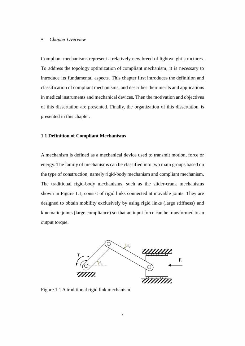
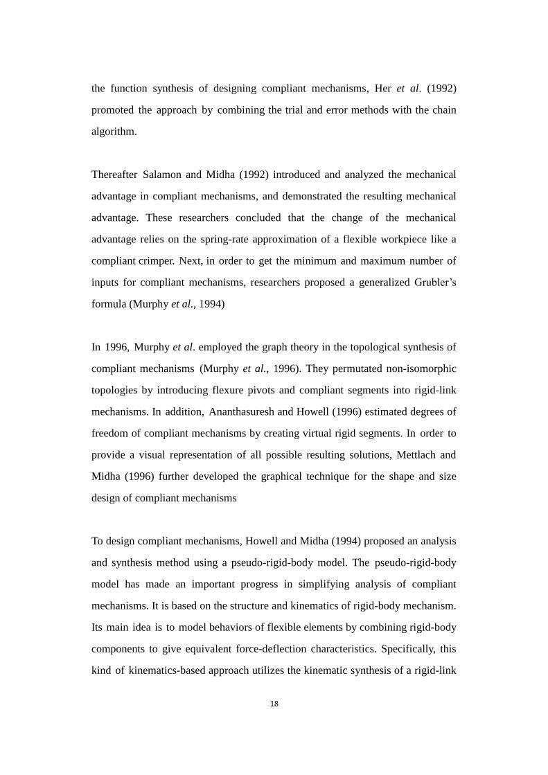
The traditional rigid-body mechanisms, such as the slider-crank mechanisms
shown in Figure 1.1, consist of rigid links connected at movable joints. They are
designed to obtain mobility exclusively by using rigid links (large stiffness) and
kinematic joints (large compliance) so that an input force can be transformed to an
output torque.
Figure 1.1 A traditional rigid link mechanism
Figure 1.1 A traditional rigid link mechanism
T
θ1 Fi
-θ2

3
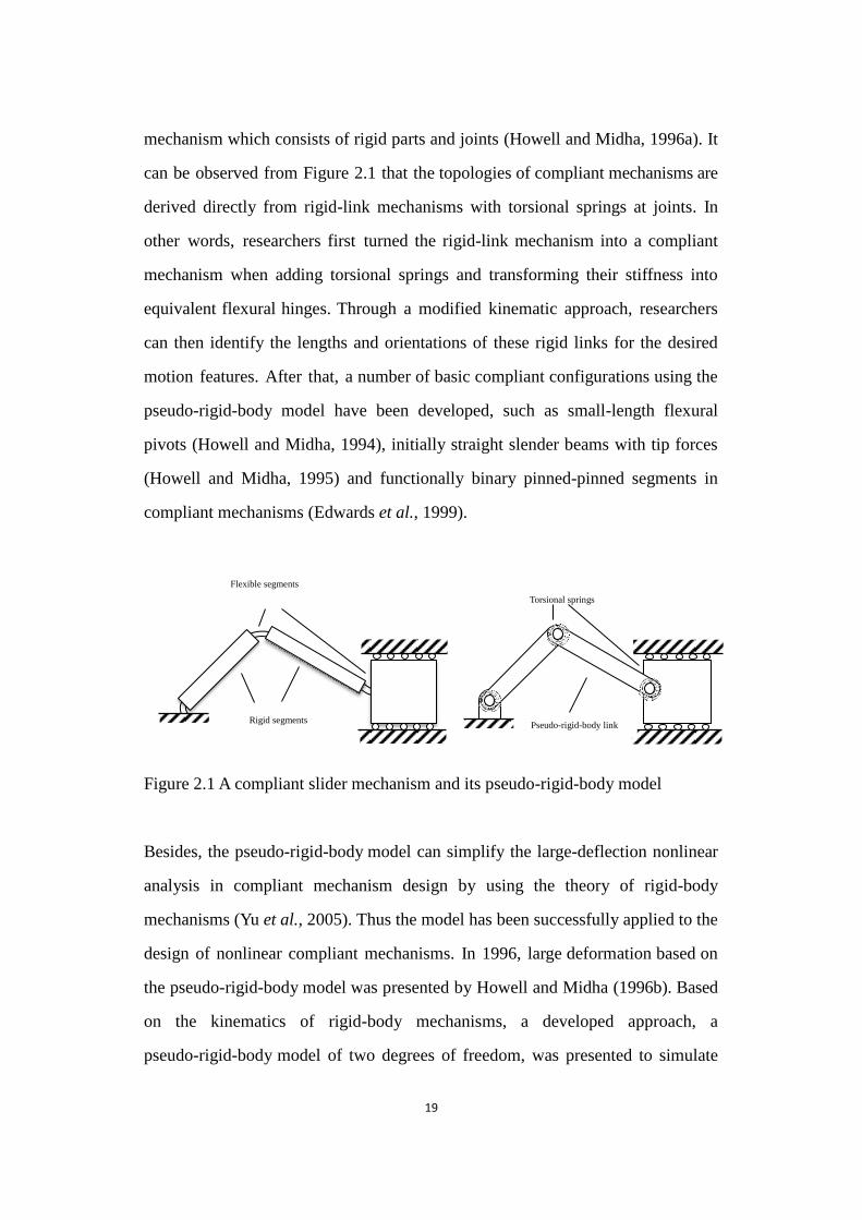
However, compliant mechanisms are single-piece flexible structures that transfer
an input force or displacement to another point through elastic deformation (Kota et
al., 2001). They can be designed in different shapes and sizes for various purposes.
As shown in Figure 1.2, compliant mechanisms are different from traditional
mechanisms consisting of rigid links connected with joints. Their mobility is
derived from structural deformation rather than the relative rigid-body motion. An
efficient compliant mechanism should be flexible enough to produce expected
kinematic motion under the action of applied loads for satisfying the flexibility
requirement. Meanwhile, for compliant mechanisms, a certain stiffness is
necessary to resist the applied input force. (Kikuchi et al., 1998; Joo et al., 2000;
Joo and Kota, 2004). Therefore, a compliant mechanism is considered as a
combination of a structure and a mechanism.
Figure 1.2 A compliant mechanism
Figure 1.2 A compliant mechanism
1.2 Classification of Compliant Mechanisms
As noted earlier, mechanisms can be divided into two groups, namely rigid-body
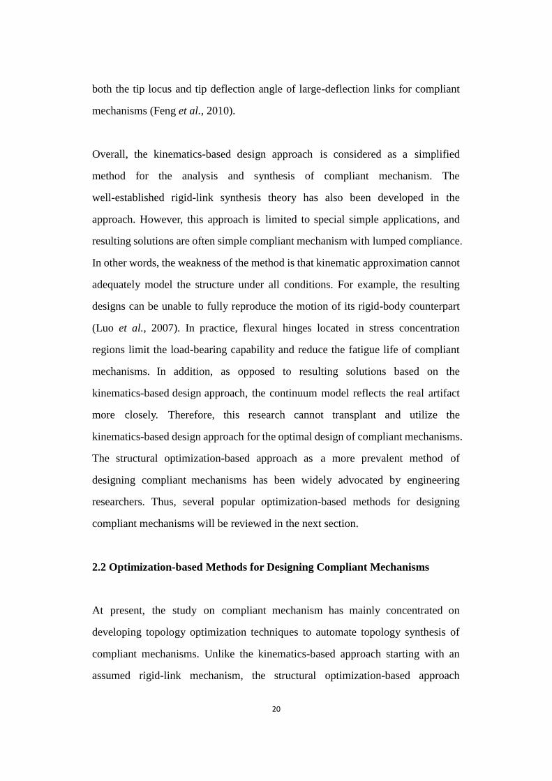
mechanisms and compliant mechanisms. Figure 1.3 illustrates the classification of
compliant mechanisms. Compliant mechanism can be classified into partially
compliant mechanisms and fully compliant mechanisms according to the various
Workpiece
Deformed configuration
Initial configuration

4
rigid and flexural members which make up the devices (Midha et al., 1994;
Cardoso and Fonseca, 2004). Partially compliant mechanisms consist of some rigid
members, traditional joints and compliant members. On the other hand, fully
compliant mechanisms do not contain mechanical joint, and the mobility is
obtained from the elastic deformation of compliant members (Howell, 2001). In
addition, compliant mechanisms can also be categorized as distributed and lumped
compliant mechanisms in terms of the distribution of compliance. More specifically,
the flexibility is concentrated in flexural hinges (or flexural pivots) for lumped
compliant mechanisms, but it is distributed throughout most compliant members
for distributed compliant mechanisms (Sigmund, 1997). This implies that
distributed compliant mechanisms can generally avoid high stress concentrations
as they can utilize most compliant members to store elastic energy.
Figure 1.3 Classification of compliant mechanisms
Figure 1.3 Classification of compliant mechanisms
Compliant Mechanisms
Partially Compliant
Mechanisms
Partially Compliant
Mechanisms Lumped
Compliance
Partially Compliant
Mechanisms Distributed Compliance
Fully Compliant
Mechanisms
Fully Compliant
Mechanisms Lumped
Compliance
Fully Compliant
Mechanisms Distributed Compliance
5
1.3 Advantages of Compliant Mechanisms
Compliant mechanisms can offer a number of benefits over traditional rigid-link
mechanisms due to the elimination or significant reduction of mechanical joints
and the existence of compliant members (Howell, 2001; Bendsøe and Sigmund,
2003). Some advantages are listed as follows:
Assembly procedures: Compliant mechanisms can be designed to be
monolithic or built using fewer parts, which means the need for assembly
procedures can be cut to a minimum (Nishiwaki et al., 1998).
No operation noise: Friction exists in rigid-body joints. Due to the absence or
reduction of mechanical joints, compliant mechanisms could produce less
operation noise when operating (Kobayashi et al., 2009).
Zero backlash: Due to the absence or reduction of mechanical joints,
compliant mechanisms suffer from less backlash. Consequently, high
precision and highly repeatable output motions can be achieved (Shuib et al.,
2007).
Light weight: Compliant mechanisms can be much lighter in weight than
rigid-link mechanisms since a flexible member contains less material than a
counterpart rigid member.
Miniaturization: One of the advantages of compliant mechanisms is the
easiness for miniature of mechanical structural devices, enabling
Micro/Nano-Mechanical Systems (MEMS/NEMS) (Ananthasuresh and

6
Howell, 2005).
Energy savings: Elastic energy is stored in compliant mechanisms after
deformation. The energy can be used to assist in application requiring a return
stage, which allows the controlled release of this energy for springs and
possible actuation.
Cost reduction: The number of parts of compliant mechanisms is largely
reduced in construction. The simplified manufacture reduces assemble costs.
In addition, there is no need for lubrication in operation. As a result,
compliant mechanisms‟ maintenance cost is much lower than their rigid-link
counterparts.
1.4 Applications of Compliant Mechanisms
Unlike rigid-link mechanisms, compliant mechanisms take advantage of the elastic
deformation of their flexible members to produce force, motion or energy
transmission. Numerous favorable features are achieved. Applications of compliant
mechanisms appeared thousands of years ago such as bows and catapults.
Nowadays, compliant mechanisms can be found everywhere in everyday life, such
as in binder clips, nail clippers, staplers and so on (refer to Figure 1.4). In addition,
the application of compliant mechanisms has become increasingly prevalent in
medical instruments and mechanical devices (Kobayashi et al., 2009).

7
Figure 1.4 Compliant devices: a binder clip, scissor and single-piece stapler
Figure 1.4 Compliant devices: a binder clip, scissor and single-piece stapler
Mechanical applications: Some current and potential practical applications
have been presented in aeromechanics, robotics and automation. Shape
morphing aircraft structures based on compliant mechanism technologies can
significantly enhance air vehicle performance (Kota et al., 2003). In addition,
compliant mechanisms are quite suitable for micro electro-mechanical
(MEMS) devices like micro grippers (Lee et al., 2003) and crimping devices
(Kota et al., 2001) owing to minimal or no assembly. Additionally, compliant
mechanisms have been applied for hand-held tools based on single-piece
compliant mechanisms like pliers and shears, manufacturing devices like
grippers, flexible fixtures and flexible robotic manipulators, optical
instruments like mirror adjustment devices and balance devices like
automotive suspension (Allred, 2003).
Medical instruments: Biomedical and biomechanical engineering are quickly
emerging areas of research. Applications of compliant mechanisms have been
extended to these fields such as surgical forceps (Howell, 2001) and medical
knee brace (Erdman et al., 2001). Due to the absence of mechanical joints,
compliant instruments can be cleaned and sterilized more easily. In addition,
the benefits of flex-feet with compliant members over traditional prosthetic
feet are their light weight and compliance.
8
1.5 Motivation of the Dissertation
The main motivation of this dissertation is to design compliant mechanisms using
the bi-directional evolutionary structural optimization (BESO) method. At present,
a large amount of effort has also gone into establishing and developing topology
optimization of compliant mechanisms (Luo and Tong, 2008). However, previous
research has been facing many challenges and shortages in several aspects such as
optimization method, optimization algorithm and resulting topology.
Firstly, to achieve structural design of compliant mechanisms, various topology
optimization methods have been widely exploited and used in this design field.
Nevertheless, previous optimization methods often produce vague topologies of
compliant mechanisms, which can be found in previous literature (Sigmund, 1997;
Nishiwaki et al., 1998; Lau et al., 2001; Bendsøe and Sigmund, 2003). The
modified BESO method proposed in this research can effectively update discrete
design variables to generate clear solutions. In addition, the previous optimization
process often experiences a long convergence history, like the level-set method,
so an efficient optimization tool with high computational efficiency is considered
for the optimal design of compliant mechanisms in this study.
Secondly, input displacement is often considered as a constraint and cited in
previous optimization algorithms. However, its role is not to ensure a certain
amount of flexibility exists in a mechanism, which is used to cause elastic
deformation according to the definition of compliant mechanism. This is not very
suitable for compliant mechanism design to investigate the real physical
significance. Reasonable constraints are quite indispensable to balance flexibility
and rigidity effectively for optimizing compliant mechanisms with linear or
geometrically nonlinear behavior.
9
Thirdly, designs of compliant mechanisms using topology optimization techniques
naturally lead to the introduction of hinges into final topologies, making them
function essentially as rigid-body mechanisms (Rahmatalla and Swan, 2005). The
material around flexural hinges is easily subject to overstress and overstrains.
Therefore, current formulations should be promoted for controlling and
precluding de facto hinge regions to generate 2D and 3D hinge-free numerical
examples.
Fourthly, previous research focuses mainly on the optimal design of linear
compliant mechanisms. In fact, optimal design of compliant mechanisms using
linear analysis is not very accurate as force and motion transmission is often
achieved through large deformation. Geometrically large deformation continuum
models should be incorporated in the optimal design to appropriately capture the
real behavior of large-displacement compliant mechanisms. Furthermore, the
convergence will experience difficulties due to the extreme deformation of
low-density elements (Luo and Tong, 2008). With the help of the hard-kill BESO
method, this systemic design approach will be especially suitable for solving this
problem.
Overall, it is quite necessary to devote efforts to the modification and promotion
of previous topology optimization techniques for constructing practical compliant
mechanism designs. It would also be desirable to use the models exhibited in this
dissertation into practical applications.
1.6 Aims and Objectives

10
This dissertation aims to propose a new BESO method for the topology
optimization of compliant mechanisms. The specific objectives are:
(1) To introduce a new BESO method into the systematic design of compliant
mechanisms.
(2) To establish new computational algorithms for the optimal design of
compliant mechanisms
(3) To incorporate nonlinear analysis procedures of compliant mechanisms into
the topology synthesis method.
(4) To exhibit a number of 2D and 3D examples for verifying proposed
optimization techniques.
(5) To find a suitable technique for industrial applications.
1.7 Organization of the Dissertation
This dissertation consists of eight chapters:
Chapter 1 of the dissertation presents the definition, classification, advantages
merits and application fields of compliant mechanisms. In addition, this
dissertation proposes the motivation to the research. Next, the purpose and
objectives of this study are also introduced. Finally, the outline of this dissertation
is proposed.

11
Chapter 2 first surveys past and present research of designing compliant
mechanisms using kinematic-based approaches and more recent structural
optimization-based approaches such as Solid Isotropic Material with Penalization
(SIMP), the level-set method and other methods. In addition, the chapter
introduces the evolutionary structural optimization (ESO) method. Next, the
chapter reviews the later version of ESO, the BESO method, including its basic
concepts, related theory and its applications in structural optimization.
Chapter 3 aims to propose a revised version of the BESO method for topology
optimization of compliant mechanism because the traditional BESO method is not
suitable to being directly applied to this design field. In this chapter, related
techniques are discussed, such as material distribution theory, the filter scheme,
stability process, element density transformation and convergence criterion.
Numerical examples are shown of its effectiveness and practicability.
Chapter 4 adopts a modified BESO method to produce sets of resulting topologies
of compliant mechanisms, and different objectives are considered to achieve
various functional behaviors. A sensitivity analysis is conducted by applying an
adjoint method. Next, numerical applications are performed to demonstrate the
capability and effectiveness of the developed method for the optimal design of
compliant mechanisms. Finally, this chapter discusses and analyses effects of the
attached springs on the topology optimization of compliant mechanisms.
Chapter 5 uses a new optimization formulation with compliance and volume
constraints, establishing the topology synthesis approach based on a modified
BESO method for designing compliant mechanisms. The new algorithm is
beneficial to control effectively the energy stored in compliant mechanisms after
deformation. Then the research analyzes the flexibility and hinge-related
12
properties through the effective control for the desired structural stiffness.
Numerical applications including 2D and 3D compliant mechanisms demonstrate
the effectiveness of the developed method and reliability of the proposed theory.
Chapter 6 defines a new optimization formulation and establishes the topology
synthesis approach based on the traditional BESO method for designing hinge-free
compliant mechanisms. The input-restrained compliance is addressed to preclude
de facto hinge regions. The sensitivity analysis is conducted by applying the
adjoint method to both the kinematical function and the structural function.
Research provides various numerical applications to demonstrate the practicability
of the developed method and the feasibility of the proposed theory.
Chapter 7 provides solutions for nonlinear compliant mechanism topologies.
Firstly, the chapter introduces structural nonlinearities and reviews solutions of
geometrically nonlinear finite element equations including incremental and
iterative methods. Furthermore, the research extends the idea of designing linear
compliant mechanisms to the optimal design of compliant mechanisms with
geometrically nonlinear behaviors. The work will define a new optimization
formulation and establish a topology synthesis approach using an end-compliance
constraint. Synthesis example is proposed and used to verify the reliability and
effectiveness of the established algorithm. Finally, insights to the topology shape
and performance characteristics are discussed following the numerical experiment.
Chapter 8 summarizes the conclusions and achievements from this research and
presents some suggestions for future research.
References
13
Allred, T. M., 2003. Compliant mechanism Suspensions, Department of Mechanical Engineering,
Brigham Young University.
Ananthasuresh, G. K. and Howell, L. L., 2005, "Mechanical design of compliant microsystems - a
perspective and prospects", Journal of Mechanical Design 127(4), 736-738.
Bendsøe, M. P. and Sigmund, O., 2003. Topology Optimization. Theory, Methods and Applications,
Springer, Berlin.
Cardoso, E. L. and Fonseca, J. S. O., 2004, "Strain energy maximization approach to the design of
fully compliant mechanisms using topology optimization", Latin American Journal of
Solids and Structures 1(3), 263-275.
Erdman, A. G., Sandor, G. N. and Kota, S., 2001. Mechanism Design: Analysis and Synthesis,
Prentice Hall, New Jersey.
Howell, L. L., 2001. Compliant Mechanisms, John Wiley & Sons, New York.
Joo, J. and Kota, S., 2004, "Topological synthesis of compliant mechanisms using nonlinear beam
elements", Mechanics Based Design of Structures and Machines 39(1), 17-38.
Joo, J., Kota, S. and Kikuchi, N., 2000, "Topological synthesis of compliant mechanisms using
linear beam elements", Mechanics of Structures and Machines 28(4), 245-280.
Kikuchi, N., Nishiwaki, S., Fonseca, J. S. O. and Silva, E. C. N., 1998, "Design optimization method
for compliant mechanisms and material microstructure ", Computer Methods in Applied
Mechanics and Engineering 151(3-4), 401-417.
Kobayashi, M., Nishiwaki, S., Izui, K. and Yoshimura, M., 2009, "An innovative design method for
compliant mechanisms combining structural optimisations and designer creativity",
Journal of Engineering Design 20(2), 125-154.
Kota, S., Hetrick, J., Osborn, R., Paul, D., Pendleton, E., Flick, P. and Tilmann, C., 2003, Design and
application of compliant mechanisms for morphing aircraft structures, Smart Structures and
Materials 2003: Industrial and Commercial Applications of Smart Structures Technologies,
SPIE, San Diego.
Kota, S., Joo, J., Li, Z., Rodgers, S. M. and Sniegowski, J., 2001, "Design of compliant mechanisms:
applications to MEMS ", Analog Integrated Circuits and Signal Processing 29(1-2), 7-15.
14
Lau, G. K., Du, H. and Lim, M. K., 2001, "Use of functional specifications as objective functions in
topological optimization of compliant mechanism", Computer Methods in Applied
Mechanics and Engineering 190(34), 4421-4433.
Lee, W. H., Kang, B. H., Oh, Y. S., Staphanou, H., Sanderson, A. C., Skidmore, G. and Ellis, M.,
2003, Micropeg manipulation with a compliant microgripper, IEEE International
Conference on Robotics and Automation, Taiwan.
Luo, Z. and Tong, L., 2008, "A level set method for shape and topology optimization of
large-displacement compliant mechanisms", International Journal for Numerical Methods
in Engineering 76(6), 862-892.
Midha, A., Norton, T. W. and Howell, L. L., 1994, "On the nomenclature, classification, and
abstractions of compliant mechanisms", Journal of Mechanical Design 116(1), 270-279.
Nishiwaki, S., Frecker, M. I., Min, S. and Kikuchi, N., 1998, "Topology optimisation of compliant
mechanisms using the homogenization method", International Journal for Numerical
Methods in Engineering 42(3), 535-559.
Rahmatalla, S. and Swan, C. C., 2005, "Sparse monolithic compliant mechanisms using continuum
structural topology optimization", International Journal for Numerical Methods in
Engineering 62(12), 1579-1605.
Shuib, S., Ridzwan, M. I. Z. and Kadarman, A. H., 2007, "Methodology of compliant mechanisms
and its current developments in applications: a review", American Journal of Applied
Sciences 4(3), 160-167.
Sigmund, O., 1997, "On the design of compliant mechanisms using topology optimization",
Mechanics of Structures and Machines 25(4), 493-524.

15
Chapter 2
Literature Review

16
Chapter Overview
In order to design ideal compliant mechanisms, many approaches have been
adopted by engineering researchers. This chapter introduces two main approaches
provided by researchers for the systematic design of compliant mechanisms. One
of the two, the structural optimization-based approach, is more prevalent in the
field of compliant mechanism design. Thus the chapter first describes most design
criteria used in topology optimization of compliant mechanisms, reviewing and
discussing previous research related to the optimal design of compliant
mechanisms using continuum-based methods. Then the chapter describes present
structural optimization approaches, such as homogenization method, the level-set
method and the ESO method. Next, this chapter focuses on the review of the
BESO method, which is the topology optimization method closely related to this
study. Finally, general remarks are presented in this chapter.
2.1 Kinematic-based Methods for Designing Compliant Mechanisms
Many structural design approaches have been applied to the synthesis of compliant
mechanisms over the years. There are two main approaches provided by
researchers in the systematic design of compliant mechanisms, namely the
kinematics-based approach and the structural optimization-based approach
(Howell, 2001). The former is built on traditional rigid-link design techniques, and
the latter seeks optimum compliant structure.
One of the two mentioned approaches, the kinematics-based compliant
mechanism technique, was developed and measured the effects from compliant
members by appropriately simulating mechanism behaviors. The approach has
been successfully applied to the design of lumped compliant mechanisms and
17
mechanisms with cantilever-like flexible links. Related design techniques, like
kinematic chains, Burmester theory and graphical synthesis methods have also
been proposed and modified for designing compliant mechanisms (Hill and Midha,
1990; Howell and Midha, 1994; Mettlach and Midha, 1996).
Specifically, engineering researchers considered lumped compliant segments to be
appropriate substitutes for revolute joints, taking advantage of trial and error
methods to design the dimensions of these compliant hinges. In 1965, Paros and
Weisbord analyzed the behavior of flexural pivots, providing equations for
calculating linear deflections produced by loads on hinge axes of flexure hinges
(Paros and Weisbord, 1965). Then, Burns and Crossley presented type synthesis
methods for flexible link mechanisms (Burns and Crossley, 1966), and proposed an
overlay technique for the design of a four-bar linkage (Burns and Crossley, 1968).
In 1987, Midha and Howell (1987) first explored the research in the field of
compliant mechanism by taking advantage of the kinematics-based synthesis
method. The research defined concepts of compliant mechanism, link compliance
and the degree of compliance concept based on a modified Grubler‟s equation
(Her and Midha, 1987). In addition, Midha et al. presented the classification of
compliant mechanisms based on link and segment characteristics and analyzed
kinematic properties of complaint mechanisms. Researchers then derived several
compliant mechanisms where rigid links were replaced by flexible links, and
discrete compliances were imposed at the joints of rigid-link kinematic chain
(Midha et al., 1992a; Midha et al., 1992b; Midha et al., 1994).
A computationally more efficient procedure, called the chain algorithm, was
presented and formed for the nonlinear deformation analysis of compliant
mechanisms (Hill and Midha, 1990; Midha et al., 1992). Furthermore, to address
18
the function synthesis of designing compliant mechanisms, Her et al. (1992)
promoted the approach by combining the trial and error methods with the chain
algorithm.
Thereafter Salamon and Midha (1992) introduced and analyzed the mechanical
advantage in compliant mechanisms, and demonstrated the resulting mechanical
advantage. These researchers concluded that the change of the mechanical
advantage relies on the spring-rate approximation of a flexible workpiece like a
compliant crimper. Next, in order to get the minimum and maximum number of
inputs for compliant mechanisms, researchers proposed a generalized Grubler‟s
formula (Murphy et al., 1994)
In 1996, Murphy et al. employed the graph theory in the topological synthesis of
compliant mechanisms (Murphy et al., 1996). They permutated non-isomorphic
topologies by introducing flexure pivots and compliant segments into rigid-link
mechanisms. In addition, Ananthasuresh and Howell (1996) estimated degrees of
freedom of compliant mechanisms by creating virtual rigid segments. In order to
provide a visual representation of all possible resulting solutions, Mettlach and
Midha (1996) further developed the graphical technique for the shape and size
design of compliant mechanisms
To design compliant mechanisms, Howell and Midha (1994) proposed an analysis
and synthesis method using a pseudo-rigid-body model. The pseudo-rigid-body
model has made an important progress in simplifying analysis of compliant
mechanisms. It is based on the structure and kinematics of rigid-body mechanism.
Its main idea is to model behaviors of flexible elements by combining rigid-body
components to give equivalent force-deflection characteristics. Specifically, this
kind of kinematics-based approach utilizes the kinematic synthesis of a rigid-link
19
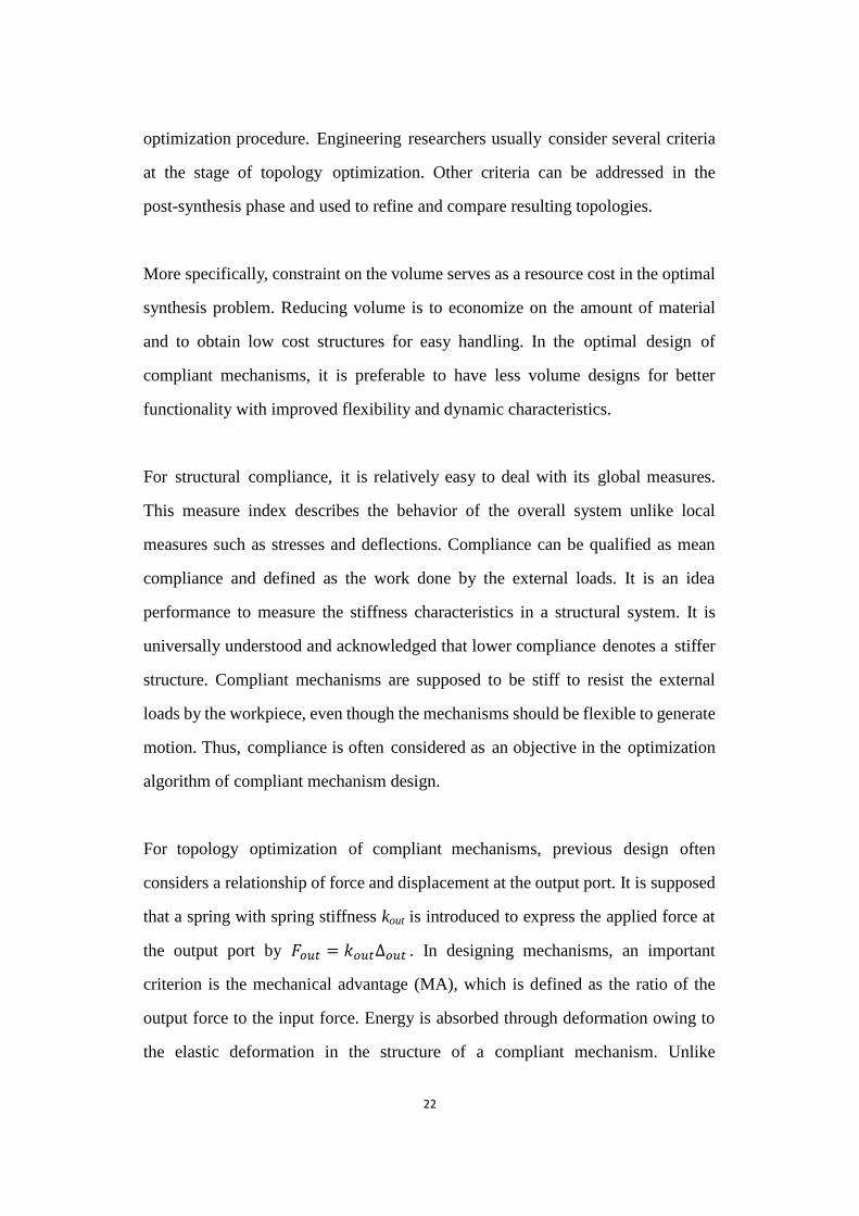
mechanism which consists of rigid parts and joints (Howell and Midha, 1996a). It
can be observed from Figure 2.1 that the topologies of compliant mechanisms are
derived directly from rigid-link mechanisms with torsional springs at joints. In
other words, researchers first turned the rigid-link mechanism into a compliant
mechanism when adding torsional springs and transforming their stiffness into
equivalent flexural hinges. Through a modified kinematic approach, researchers
can then identify the lengths and orientations of these rigid links for the desired
motion features. After that, a number of basic compliant configurations using the
pseudo-rigid-body model have been developed, such as small-length flexural
pivots (Howell and Midha, 1994), initially straight slender beams with tip forces
(Howell and Midha, 1995) and functionally binary pinned-pinned segments in
compliant mechanisms (Edwards et al., 1999).
Figure 2.1 A compliant slider mechanism and its pseudo-rigid-body model
Figure 2.1 A compliant slider mechanism and its pseudo-rigid-body model
Besides, the pseudo-rigid-body model can simplify the large-deflection nonlinear
analysis in compliant mechanism design by using the theory of rigid-body
mechanisms (Yu et al., 2005). Thus the model has been successfully applied to the
design of nonlinear compliant mechanisms. In 1996, large deformation based on
the pseudo-rigid-body model was presented by Howell and Midha (1996b). Based
on the kinematics of rigid-body mechanisms, a developed approach, a
pseudo-rigid-body model of two degrees of freedom, was presented to simulate
Flexible segments
Rigid segments
Torsional springs
Pseudo-rigid-body link
20
both the tip locus and tip deflection angle of large-deflection links for compliant
mechanisms (Feng et al., 2010).
Overall, the kinematics-based design approach is considered as a simplified
method for the analysis and synthesis of compliant mechanism. The
well-established rigid-link synthesis theory has also been developed in the
approach. However, this approach is limited to special simple applications, and
resulting solutions are often simple compliant mechanism with lumped compliance.
In other words, the weakness of the method is that kinematic approximation cannot
adequately model the structure under all conditions. For example, the resulting
designs can be unable to fully reproduce the motion of its rigid-body counterpart
(Luo et al., 2007). In practice, flexural hinges located in stress concentration
regions limit the load-bearing capability and reduce the fatigue life of compliant
mechanisms. In addition, as opposed to resulting solutions based on the
kinematics-based design approach, the continuum model reflects the real artifact
more closely. Therefore, this research cannot transplant and utilize the
kinematics-based design approach for the optimal design of compliant mechanisms.
The structural optimization-based approach as a more prevalent method of
designing compliant mechanisms has been widely advocated by engineering
researchers. Thus, several popular optimization-based methods for designing
compliant mechanisms will be reviewed in the next section.
2.2 Optimization-based Methods for Designing Compliant Mechanisms
At present, the study on compliant mechanism has mainly concentrated on
developing topology optimization techniques to automate topology synthesis of
compliant mechanisms. Unlike the kinematics-based approach starting with an
assumed rigid-link mechanism, the structural optimization-based approach

21
formulates the problem with topology optimization formulations. Therefore,
structural optimization techniques can allow for a more fundamental approach for
the optimal design of compliant mechanisms by integrating principles of
kinematics and structural mechanics. Their application in the compliant mechanism
synthesis will be reviewed and discussed in the following sections.
2.2.1 Design Criteria of Compliant Mechanisms in Optimization-based Methods
It is necessary to first give a brief review of some related concepts, theories and
design criteria applied in topology optimization of compliant mechanisms. To
design compliant mechanisms with distributed compliance in topology
optimization, the primary objective is to consider functional behavior. That means
that the synthesis approach should be able to produce a suitable structural
configuration so that resulting solutions are able to achieve their functional
behaviors (Ananthasuresh, 1994). The following design criteria are usually
addressed and applied in compliant mechanism designs using structural
optimization-based methods at both macro and micro levels: (a) Geometric
advantage (the ratio of output displacement to input displacement); (b) Mechanical
advantage (the ratio of output force to input force); (c) Mechanical efficiency (the
product of geometric advantage and mechanical advantage); (d) Volume and
weight of material; (e) Compliance (work done by external forces); (f) Size and
space constraints; (g) Industrial manufacturability; (h) Acceptable strain levels; (i)
No stress concentration regions; (j) Acceptable fatigue strength; (k) Ergonomics
and aesthetics.
Certainly, it is obvious that it is not possible to quantify all design criteria of the
above performance characteristics for topology optimization of compliant
mechanisms. Thus it is not easy to incorporate all performances into the
22
optimization procedure. Engineering researchers usually consider several criteria
at the stage of topology optimization. Other criteria can be addressed in the
post-synthesis phase and used to refine and compare resulting topologies.
More specifically, constraint on the volume serves as a resource cost in the optimal
synthesis problem. Reducing volume is to economize on the amount of material
and to obtain low cost structures for easy handling. In the optimal design of
compliant mechanisms, it is preferable to have less volume designs for better
functionality with improved flexibility and dynamic characteristics.
For structural compliance, it is relatively easy to deal with its global measures.
This measure index describes the behavior of the overall system unlike local
measures such as stresses and deflections. Compliance can be qualified as mean
compliance and defined as the work done by the external loads. It is an idea
performance to measure the stiffness characteristics in a structural system. It is
universally understood and acknowledged that lower compliance denotes a stiffer
structure. Compliant mechanisms are supposed to be stiff to resist the external
loads by the workpiece, even though the mechanisms should be flexible to generate
motion. Thus, compliance is often considered as an objective in the optimization
algorithm of compliant mechanism design.
For topology optimization of compliant mechanisms, previous design often
considers a relationship of force and displacement at the output port. It is supposed
that a spring with spring stiffness kout is introduced to express the applied force at
the output port by 𝐹𝑜𝑢𝑡 = 𝑘𝑜𝑢𝑡∆𝑜𝑢𝑡 . In designing mechanisms, an important
criterion is the mechanical advantage (MA), which is defined as the ratio of the
output force to the input force. Energy is absorbed through deformation owing to
the elastic deformation in the structure of a compliant mechanism. Unlike
23
rigid-body mechanisms, the general relations for the mechanical advantage of
single-input and single-output port compliant mechanisms are more involved and
can be formulated as 𝑀𝐴 = 𝐹𝑜𝑢𝑡 𝐹𝑖𝑛 = 𝛿∆𝑖𝑛 𝛿∆𝑜𝑢𝑡 − 𝛿𝐸 (𝛿∆𝑜𝑢𝑡𝐹𝑖𝑛)⁄⁄⁄ =
= 𝑀𝑟 −𝑀𝑐 (Salamon and Midha, 1998). 𝛿𝐸 represents the incremental change in
the total strain energy of the compliance mechanism. The term 𝑀𝑟 takes the form
of the mechanical advantage of a rigid-like mechanism. The term 𝑀𝑐 accounts for
the strain energy stored in the mechanism (Wang, 2009). In addition, Larsen et al.
(1997) proposed the concept of geometrical advantage (GA) since the measure of
motion transfer is no longer implied in the concept of mechanical advantage. It can
be defined as the ratio of output displacement to input displacement. It is given by
𝐺𝐴 = ∆𝑜𝑢𝑡 ∆𝑖𝑛⁄ . On the other hand, work ratio, which measures the efficiency of
work transfer, is the ratio of output work to input work, 𝑀𝐸 = 𝑀𝐴 × 𝐺𝐴 (Lau et
al., 2001).
Overall, the above mentioned design criterion are critical to topology optimization
of compliant mechanism. In particular, structural compliance and the relationship
of force and displacement are often applied to optimization formulations in current
structural optimization-based methods like the density-based method and level-set
method. Some other design criteria are also addressed by engineering researchers
to refine and compare resulting topologies (Ananthasuresh et al., 1994).
2.2.2 Optimal Design of Compliant Mechanisms Using Homogenization
Methods
With establishing mentioned design criteria for continuum-based models of
compliant mechanisms, various topology optimization methods have been applied
in this design field. The homogenization method is viewed as the first
continuum-based method used to optimize the distributed compliance of compliant
24
mechanisms.
Anathasuresh et al. originally developed the homogenization method as a structural
optimization technique for the synthesis of compliant mechanisms (Ananthasuresh
et al., 1993; Ananthasuresh et al., 1994). Thereafter Frecker et al. (1997) adopted
the homogenization method for solving topology optimization problems of
compliant mechanisms by introducing a mutual energy concept. In their study, the
formulation was based on a multi-criteria optimization procedure for single output
cases to analyze compliant mechanisms‟ performances and satisfy their different
design requirements. Specifically, these researchers proposed objective functions
according to the different types of combinations of mutual potential energy and
strain energy needed to accomplish the design objectives of maximizing the
former and minimizing the latter simultaneously, namely a weighted linear
combination and a ratio equation. Kikuchi et al. (1998) displayed the design of the
optimum layout of compliant mechanisms by minimizing weight subject to a
prescribed elasticity tensor constraint.
In 1998, Nishiwaki et al. performed an investigation on the Pareto optimality
conditions of the multi-criteria compliant mechanism formulation (Nishiwaki et al.,
1998). The advantage of the proposed approach is that it can determine all Pareto
optimal designs. The optimization algorithm formulates the structural flexibility
based on the previous mutual energy concept. Specifically, the mutual mean
compliances of a structure were interpreted according to an elastic body subjected
to two different tractions. Then the formulation is to maximize the mutual mean
compliance for sufficient flexibility of the structure. In addition, the researchers
considered that both kinematic function and structural function were required in
the compliant mechanism design. In order to resist reaction forces from a
workpiece and maintain structural shape, the sufficient rigidity should be obtained

25
by considering minimizing the mean compliance from the design domain, the
input port of which is fixed.
Typical examples can be found in Figure 2.2, where these researchers proposed
the optimal topology configurations for a compliant gripper with different
material volumes. These bear significance to the optimal design compliant
mechanisms, but some shortcomings of the resulting solutions are immediately
apparent. For examples, the optimization technique generates vague topologies
since the intermediate densities of elements are not polarized very well. In
addition, the total volume constraint significantly affects the optimal shape. It can
also be observed from Figure 2.2 that resulting topologies are not really similar
for using different volume constraints and the problem with respect to structural
connectivity exists in the resulting topology with lower volume material.
Figure 2.2 Optimal configurations of compliant gripper with different total volume constraints using the homogenization method
Figure 2.2 Optimal configurations of compliant gripper with different total
volume constraints using the homogenization method (Nishiwaki et al., 1998)
Although the homogenization method first exploited topology optimization
compliant mechanisms and it has a great significance in optimizing compliant
mechanisms using continuum-based models, this dissertation will not apply the
homogenization method to the optimal design of compliant mechanisms. The
research should seek and develop an optimization approach, which can produce
clear and stable final designs of compliant mechanisms.

26
2.2.3 Optimal Design of Compliant Mechanisms Using Solid Isotropic Material
with Penalization
The Solid Isotropic Material with Penalization (SIMP) method has been
developed for solving compliant mechanism design problem. Sigmund (1997)
described this density-based method for the optimal design of compliant
mechanism. In Sigmund‟s work, a sequential linear programming approach is
introduced in the optimization algorithm. The objective is to maximize the
mechanical advantage of a compliant mechanism subject to a limited material
volume and total input constraint. There are different numerical examples
optimized and exhibited by Sigmund to demonstrate the influence of workpiece
stiffness and size on the optimal mechanism topology. Figure 2.3 displays the
optimal configurations of compliant grippers with one output and two outputs
using this density-based method. When compared with resulting topologies
produced by the homogenization method, solutions are more complex and reflect
the real artifact more closely. However, some features, such as vague resulting
designs and one-node connected hinges, are unexpected in industrial
manufacturing.
Figure 2.3 Optimal configurations of compliant gripper with one output and two outputs using the density-based method
Figure 2.3 Optimal configurations of compliant gripper with one output and two

27
outputs using the density-based method (Sigmund, 1997)
Larsen et al. (1997) also proposed a density-based way to design the topology and
shape of compliant mechanisms by specifying the elastic properties of materials.
The researchers used a least squared formulation, which allows designers to create
mechanisms with a minimum error between the measured and required
mechanical advantage. Despite satisfactory kinematic requirements, resulting
topologies exhibited thin flexure-like components.
To solve the topological design of compliant mechanisms, Lau et al. (2001)
suggested the optimization method on the basis of the combination of the moving
asymptotes technique and the SIMP model without the filtering scheme. Luo et al.
(2005) formulated the optimization problem for compliant mechanism designs
using the rational approximation of material properties density, which is opposed to
the SIMP model. A set of optimal results of compliant mechanisms are exhibited
to illustrate that the optimization algorithm using either the density or sensitivity
filter scheme is efficient at eliminating checkerboards, but one-node connected
hinges can only be prevented for a small output export. Finally, the researchers
employed a hybrid-filtering scheme, and concluded that no one-node connected
hinges appear in final designs. However, in fact, one-node connected hinges can
only be prevented to some degree, because there are still obvious hinge regions in
resulting solutions.
In addition, Lin et al. (2010) proposed a method for implementing multi-objective
optimization of compliant mechanisms on the basis of the combination of the SIMP
model and the physical programming. The proposed framework aims to bring
flexibility, robustness and adaptability to multi-objective optimization. A set of
resulting designs were presented to demonstrate the effect of multi-objective
28
optimization on topologies in compliant mechanism design.
To capture the natural behavior of nonlinear compliant mechanisms, the SIMP
model and related density-based methods have been advocated and extended to
deal with synthesis of large-displacement compliant mechanisms. Bruns and
Tortorelli (1998) began to address geometrical nonlinearity for topology synthesis
for structure design. In 2001, they used the method of moving asymptotes to solve
the topology optimization problem of nonlinear compliant mechanisms (Bruns and
Tortorelli, 2001). Furthermore, Pedersen et al. (2001) incorporated geometrical
nonlinearity in topology optimization of compliant mechanism design based on
the variable density method. These authors first solved the nonlinear
force-displacement curve and path generation problems. Then they proposed a
topology design formulation of large-displacement compliant mechanisms based
on a multi-criteria objective function, describing the derivation of sensitivity of
output displacement in relation to the design variables. In addition, Yoon and Kim
(2005) described topology optimization of geometrically nonlinear structures,
including compliant mechanisms, using the density-based method. In order to
avoid the numerical instability caused by the SIMP formulation, these researchers
reformulated the optimization problem as seeking the optimal inter-element
connectivity distribution by element connectivity parameterization. In 2008, Du et
al. (2008) employed a topology optimization of geometrical nonlinear complaint
mechanisms using the element-free Galerkin method, in which design domain
was discretized by nodes rather than elements. Then the SIMP scheme is
addressed to represent the nonlinear dependence between material properties and
regularized discrete densities. The mathematical model of a compliant mechanism
was expressed as maximizing its output displacement.
To sum up, previous engineering researchers have taken advantage of the SIMP
29
method to improve topology optimization of compliant mechanisms. The
techniques have been extended to solve more complicated problems of designing
compliant mechanisms and are capable of producing relatively complex designs.
However, vague resulting topologies also frequently appear in previous work
when considering the SIMP method.
2.2.4 Optimal Design of Compliant Mechanisms Using Level-set Method
Most recently, the level-set method has been presented to perform shape and
topology optimization of elastic compliant mechanism. For example, Wang et al.
(2005) proposed the level-set method for the optimal design of monolithic
compliant mechanisms with multiple materials. A multiphase model adopted in
their research aims to specify material regions and sharp interfaces of single-input
and single-output multi-material mechanisms.
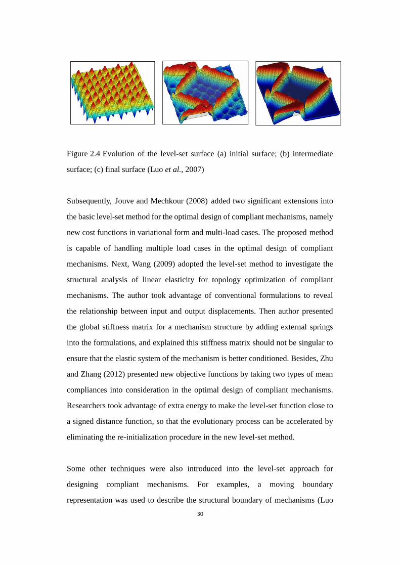
In addition, Luo et al. (2007) employed the parameterization level set technique for
the shape and topology optimization using a compactly supported radial basis
function. In contrast to conventional level-set method, authors discretized the
Hamilton-Jacobi equation into a set of algebraic equations so that the initial
topology optimization could be considered as a parameterization problem. The
design problem of compliant mechanisms was then formulated as maximizing
mechanical efficiency. Finally, authors proposed the topology optimization of a
compliant inverter. Related level-set surfaces are given in Figure 2.4. The design
domain initialized with a number of holes. The mechanical efficiency increased
during the first 70 iterations. The final design was achieved at Iteration 322 as
shown in Figure 2.4c.
30
Figure 2.4 Evolution of the level-set surface
Figure 2.4 Evolution of the level-set surface (a) initial surface; (b) intermediate
surface; (c) final surface (Luo et al., 2007)
Subsequently, Jouve and Mechkour (2008) added two significant extensions into
the basic level-set method for the optimal design of compliant mechanisms, namely
new cost functions in variational form and multi-load cases. The proposed method
is capable of handling multiple load cases in the optimal design of compliant
mechanisms. Next, Wang (2009) adopted the level-set method to investigate the
structural analysis of linear elasticity for topology optimization of compliant
mechanisms. The author took advantage of conventional formulations to reveal
the relationship between input and output displacements. Then author presented
the global stiffness matrix for a mechanism structure by adding external springs
into the formulations, and explained this stiffness matrix should not be singular to
ensure that the elastic system of the mechanism is better conditioned. Besides, Zhu
and Zhang (2012) presented new objective functions by taking two types of mean
compliances into consideration in the optimal design of compliant mechanisms.
Researchers took advantage of extra energy to make the level-set function close to
a signed distance function, so that the evolutionary process can be accelerated by
eliminating the re-initialization procedure in the new level-set method.
Some other techniques were also introduced into the level-set approach for
designing compliant mechanisms. For examples, a moving boundary
representation was used to describe the structural boundary of mechanisms (Luo
31
et al., 2008). The element connectivity parameterization method was integrated in
a level-set framework of designing compliant mechanisms (Dijk et al., 2010). The
phase field method was taken into consideration in optimizing shape and topology
of compliant mechanisms based on the level-set method (Takezawa et al., 2010;
Yamada et al., 2010). The method of moving asymptotes was applied to update
the level-set function for designing compliant mechanisms, considering a mutual
mean compliance constraint and a stress constraint (Otomori et al., 2011).
In addition, several researchers attempted to utilize the level-set method to
eliminate de facto hinges in compliant mechanisms because topology
optimization of hinge-free compliant mechanisms has received more attention and
has undergone considerable developments in recent years. For example, Luo et al.
(2008) took advantage of a semi-implicit scheme on the basis of an additive
operator-splitting algorithm to solve the Hamilton-Jacobi partial differential
equation in the level-set method. Then a quadratic energy functional derived
mainly from image active contour technique was introduced into the optimization
algorithm. It can generate hinge-free compliant mechanisms by controlling
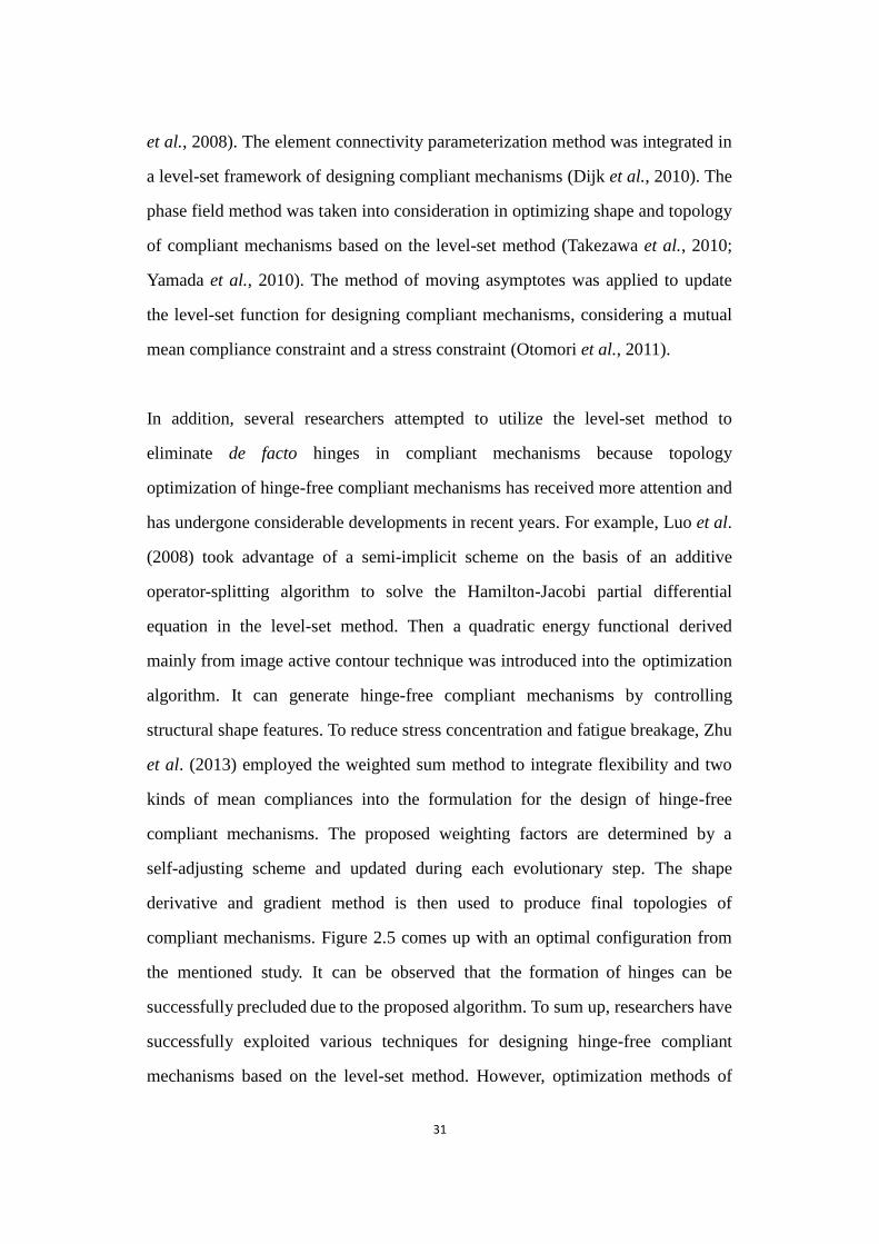
structural shape features. To reduce stress concentration and fatigue breakage, Zhu
et al. (2013) employed the weighted sum method to integrate flexibility and two
kinds of mean compliances into the formulation for the design of hinge-free
compliant mechanisms. The proposed weighting factors are determined by a
self-adjusting scheme and updated during each evolutionary step. The shape
derivative and gradient method is then used to produce final topologies of
compliant mechanisms. Figure 2.5 comes up with an optimal configuration from
the mentioned study. It can be observed that the formation of hinges can be
successfully precluded due to the proposed algorithm. To sum up, researchers have
successfully exploited various techniques for designing hinge-free compliant
mechanisms based on the level-set method. However, optimization methods of
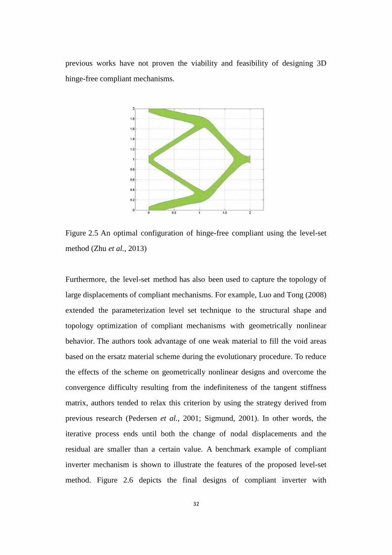
32
previous works have not proven the viability and feasibility of designing 3D
hinge-free compliant mechanisms.
Figure 2.5 An optimal configuration of hinge-free compliant using the level-set method
Figure 2.5 An optimal configuration of hinge-free compliant using the level-set
method (Zhu et al., 2013)
Furthermore, the level-set method has also been used to capture the topology of
large displacements of compliant mechanisms. For example, Luo and Tong (2008)
extended the parameterization level set technique to the structural shape and
topology optimization of compliant mechanisms with geometrically nonlinear
behavior. The authors took advantage of one weak material to fill the void areas
based on the ersatz material scheme during the evolutionary procedure. To reduce
the effects of the scheme on geometrically nonlinear designs and overcome the
convergence difficulty resulting from the indefiniteness of the tangent stiffness
matrix, authors tended to relax this criterion by using the strategy derived from
previous research (Pedersen et al., 2001; Sigmund, 2001). In other words, the
iterative process ends until both the change of nodal displacements and the
residual are smaller than a certain value. A benchmark example of compliant
inverter mechanism is shown to illustrate the features of the proposed level-set
method. Figure 2.6 depicts the final designs of compliant inverter with
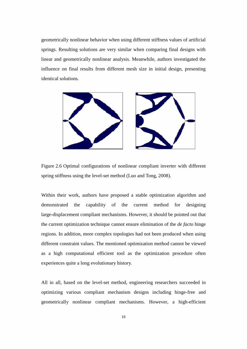
33
geometrically nonlinear behavior when using different stiffness values of artificial
springs. Resulting solutions are very similar when comparing final designs with
linear and geometrically nonlinear analysis. Meanwhile, authors investigated the
influence on final results from different mesh size in initial design, presenting
identical solutions.
Figure 2.6 Optimal configurations of nonlinear compliant inverter with different spring stiffness using the level-set method
Figure 2.6 Optimal configurations of nonlinear compliant inverter with different
spring stiffness using the level-set method (Luo and Tong, 2008).
Within their work, authors have proposed a stable optimization algorithm and
demonstrated the capability of the current method for designing
large-displacement compliant mechanisms. However, it should be pointed out that
the current optimization technique cannot ensure elimination of the de facto hinge
regions. In addition, more complex topologies had not been produced when using
different constraint values. The mentioned optimization method cannot be viewed
as a high computational efficient tool as the optimization procedure often
experiences quite a long evolutionary history.
All in all, based on the level-set method, engineering researchers succeeded in
optimizing various compliant mechanism designs including hinge-free and
geometrically nonlinear compliant mechanisms. However, a high-efficient
34
optimization method is advised for both 2D and 3D hinge-free compliant
mechanism designs. Reasonable constraints are also indispensable to balance
effectively flexibility and stiffness for complex topologies of compliant
mechanisms with linear or geometrically nonlinear behavior.
2.2.5 Optimal Design of Compliant Mechanisms Using Other Methods
With the improvement in computational capability, discrete methods have been
applied in the design of compliant mechanisms. Saxena (2002) took advantage of
the genetic algorithm to lay out the optimal material distribution in a solid
continuum and obtained compliant mechanism with multiple materials. Parsons
and Canfield (2002) introduced a multi-objective scheme in the genetic algorithm
for a frame-element ground structure to search for the optimal compliant
mechanism topology. Saxena (2005) employed the barrier assignment of design
variables for multiple materials and used the non-dominated sorting in genetic
algorithm for the optimal design of compliant mechanisms.
In addition, the ground structure method has been employed for optimal truss
layout design (Prager, 1970; Prager, 1977), and has been extended to compliant
mechanism synthesis. Sigmund (1994) parameterized the design domain based on
a truss ground structure from Bendsøe‟s work, in which the optimal microstructures
have mechanism-type motions subject to loads differing from the design load. A set
of grid nodes are firstly used to discretize the design domain. Then the optimization
technique connects each grid node with every other node by truss or frame to create
a fully grounded structure. In fact, ground structure is typically used as a general
term including both fully and partially grounded structures. Both truss and frame
ground structures have also been extended to the topology synthesis of compliant
mechanisms with using the element‟s cross sections as the design variables.
35
However, behaviors of compliant mechanisms can be more accurately captured by
frame elements, as the bending of beam-like segments can produce better the
mobility than the lengthening and shortening of trusses.
Material removal strategies have been adopted in the structural optimization
(Rodriguez- Velazquez and Seireg, 1985; Xie and Steven, 1993). For example, a
modified evolutionary structural optimization (Additive ESO) procedure with an
additive strategy was proposed by Ansola et al. (2007) , and it was applied to 3D
compliant mechanisms (Ansola et al., 2010) and thermal effects (Ansola et al.,
2010). In addition, Veguería et al. (2008) proposed a new objective function
combined with Additive ESO for the optimal design of compliant mechanisms with
spring models.
Overall, the selection of an optimization method is vitally important for the
topology optimization of complaint mechanisms. Thus the current structural
optimization techniques will be described in the next sections. In particular,
efficient design tools, ESO and BESO, will be reviewed in this dissertation as they
are closely related to this research.
2.3 Topology Optimization Methods
The use of topology optimization methods is critical to compliant mechanism
design. Over the last three decades, researchers have made great efforts to develop
structural optimization techniques. Analytical and numerical techniques were
exploited to solve a multitude of structural design problems. The original structural
optimization technique can be traced back to Galileo who obtained the optimum
shapes of variable depth beams by designing solids of equal resistance. Barnett
(1966) and Hemp (1973) described the highlights of the history of this subject from
36
Galileo to the 1960s.
Generally speaking, the present structural optimization techniques concentrated
mainly on the idea of obtaining the stiffest or strongest structural optimums given a
fixed volume or weight limitation. Related methodologies were mainly approached
using parametric geometry-based and material distribution problems. For the
former, parametric geometry-based design techniques are used for the design of the
shape and size or boundary conditions for a structure. The techniques are often
required when taking into account local constraints like stress constraints. For
material distribution problems, they aim to seek the optimal location of material
within a design domain. Related approaches are primarily employed for solving
topology or layout synthesis problems and offer the largest potential for increases
in structural performance.
Originally, Topping (1983), Levy and Lev (1987) proposed a comprehensive
reviews of previous techniques. The previous theory was then developed to
perform topology optimization of discrete structural systems and examined the
optimal layout structure. In 1904, Michell presented a developed analytical
technique for layout design of frame structure (Michell, 1904). So far, various
structural topology optimization methods, e.g. homogenization method (Bendsøe
and Kikuchi, 1988), Solid Isotropic Material with Penalization (SIMP) (Zhou and
Rozvany, 1991; Rozvany et al., 1995), level-set method (Sethian and Wiegmann,
2000; Wang et al., 2003; Allaire et al., 2004), genetic algorithm method (Chapman
et al., 1994; Chapman and Jakiela, 1996), Evolutionary Structural Optimization
(ESO) (Xie and Steven, 1993; Xie and Steven, 1997) and Bidirectional
Evolutionary Structural Optimization (BESO) (Huang and Xie, 2007; Huang and
Xie, 2009; Huang and Xie, 2010) have been developed and improved mainly for
finding the lightest, stiffest and strongest structures.
37
For the homogenization method, Cheng and Olhoff (1981) first discussed the
mathematical formulation for the optimal design of plates based on the thin plate
theory. They concluded that a global optimal solution does not generally exist
within both the class of smooth functions and the class of smooth functions with a
finite number of discontinuities. Consequently, a series of works on optimal design
problems were solved by using a microstructure. Kohn and Strang (1986) presented
the concept of relaxation for the ill-posed variational problem of formulating for
the optimal design. Rozvany et al. (1987) then investigated the implication related
to the relaxation concept with the design of perforated elastic plates. In 1988,
Bendsøe and Kikuchi proposed the homogenization method for topology
optimization and created a paradigm shift in this field (Bendsøe and Kikuchi,
1988).
Unlike the homogenization approach utilizing the sizes and orientation of the micro
void, the SIMP approach uses the material density to describe each element. From
Figure 2.7, it can be seen that the SIMP approach employs intermediate densities
for each element. The material density is penalized in order to discourage the
formation of intermediate densities in structural optimization. Bendsøe (1989) first
considered the SIMP approach, in which an artificial density was introduced for
predicting the topology of a mechanical element. Zhou and Rozvany (1991)
developed the SIMP approach independently and illustrated it with examples.
Bendsøe and Sigmund (1999) analyzed and compared the SIMP and similar
material models in the effective properties of composite materials. Their analysis
proved that the power-law approach is considered to be physically permissible as
long as simple conditions on the power are satisfied.

38
Figure 2.7 Solid continua parameterizations
Figure 2.7 Solid continua parameterizations
The level-set method as a computational technique has been developed and applied
to structural shape and topology optimization. Sethian and Wiegmann (2000) first
introduced the level-set method into the structural optimization on a fixed Eulerian
grid. The method can track the motion of structural boundaries and handle the
presence of potential topological changes. Figure 2.8 illustrates its important ideas.
The left figure displays the topology shape of a bounded region. From the right
figure, the surface is the graph of a level-set function used to determine the left
shape. So far, two main categories based on the level-set method have been
developed in structural optimization. One category takes advantage of explicit
schemes to calculate the Hamilton-Jacobi partial differential equation when
advancing the implicitly represented design boundary. In 2002, Allaire et al.
integrated the classical shape gradient into the level-set algorithm to handle
topological changes (Allaire et al., 2002). The method can be applied to linear or
nonlinear models in 2D and 3D (Allaire et al., 2004). The other category, called the
parameterization level set method, does not need to solve the Hamilton-Jacobi
partial differential equation using explicit schemes (Belytschko et al., 2003; Haber,
2004; Wang and Wang, 2006).
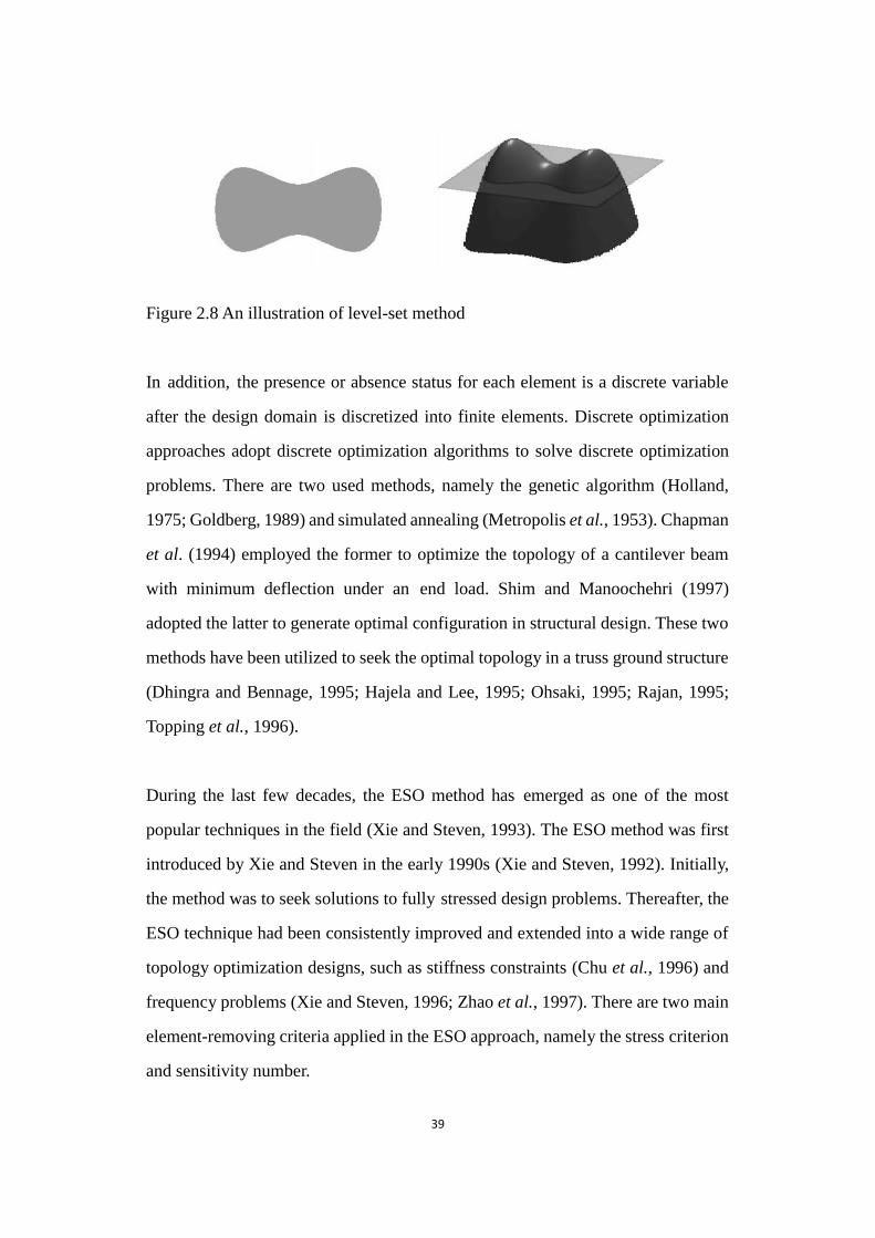
39
Figure 2.8 An illustration of level-set method
Figure 2.8 An illustration of level-set method
In addition, the presence or absence status for each element is a discrete variable
after the design domain is discretized into finite elements. Discrete optimization
approaches adopt discrete optimization algorithms to solve discrete optimization
problems. There are two used methods, namely the genetic algorithm (Holland,
1975; Goldberg, 1989) and simulated annealing (Metropolis et al., 1953). Chapman
et al. (1994) employed the former to optimize the topology of a cantilever beam
with minimum deflection under an end load. Shim and Manoochehri (1997)
adopted the latter to generate optimal configuration in structural design. These two
methods have been utilized to seek the optimal topology in a truss ground structure
(Dhingra and Bennage, 1995; Hajela and Lee, 1995; Ohsaki, 1995; Rajan, 1995;
Topping et al., 1996).
During the last few decades, the ESO method has emerged as one of the most
popular techniques in the field (Xie and Steven, 1993). The ESO method was first
introduced by Xie and Steven in the early 1990s (Xie and Steven, 1992). Initially,
the method was to seek solutions to fully stressed design problems. Thereafter, the
ESO technique had been consistently improved and extended into a wide range of
topology optimization designs, such as stiffness constraints (Chu et al., 1996) and
frequency problems (Xie and Steven, 1996; Zhao et al., 1997). There are two main
element-removing criteria applied in the ESO approach, namely the stress criterion
and sensitivity number.
40
Stress Criterion: this method is based on a simple concept that inefficient material
is gradually removed from the design domain so that the resulting topology evolves
towards an optimum. Initially, the method was to seek to solutions of fully stressed
design problems (Xie and Steven, 1993). The stress was chosen as the element
removing criteria. Elements with small von Mises stress were seen as inefficient
material to be removed. Two types of loops, inner loop and outer loop, are
incorporated in the procedure. In the loop, the procedure aims to measure the stress
level of each element after a finite element analysis. The level can be determined by
using a ratio, for example, the ratio of the von Mises stress of the element 𝜎𝑒𝑣𝑀 to
maximum von Mises stress from the whole structure 𝜎𝑚𝑎𝑥𝑣𝑀 . The indicator, the
rejection ratio (RR), is selected as the threshold stress. If the stress level of one
element is lower than the threshold stress, such as 𝜎𝑒𝑣𝑀 𝜎𝑚𝑎𝑥
𝑣𝑀 <⁄ 𝑅𝑅𝑖 during the ith
iteration step, the element will be removed for the structure. The strategy of
removing material with inefficient use is based on the idea that the stress in every
part in the structure should be close to the same and safe level. The procedure in the
outer loop is used to consider the coming rejection ratio, which can be formulated
as 𝑅𝑅𝑖+1 = 𝑅𝑅𝑖 + 𝐸𝑅 with the evolutionary ratio ER. The loop action aims to
seek the stress of quasi-uniform distributions. In 1996, this method was extended to
the optimization of structures with material and geometric nonlinearities (Querin et
al., 1996). One of these variations for the stress-based ESO technique is Nibbling
ESO (Xie and Steven, 1997). It considers only whether the elements from the
structural boundary should be removed or not instead of ones from inside the
structure domain. The ESO method was also adopted to solve thermal stress
optimization problems under thermal loadings (Li et al., 1997), and optimal contact
shape designs for elastic bodies under the multiple load cases (Li et al., 2005). This
research exhibits the resulting ESO topologies related to the stress design in
Figures 2.9.

41
Figure 2.9 Design domain and its ESO topology with RR=25% for a Michel-type structure optimization with von Mises stress criterion
Figure 2.9 Design domain and its ESO topology with RR=25% for a Michel-type
structure optimization with von Mises stress criterion (Xie and Steven, 1993)
Sensitivity Number: the significant improvement of the classical ESO method is
that the sensitivity number is adopted and regarded as the element-removing
criterion. Elements will be removed on the basis of the value of the element
sensitivity number so that the algorithm can well capture the change in the
objective function or constraint for each evolutionary procedure. Elements with
lower sensitivity number from finite element analysis will be removed to drive
structures towards optimums. Various design problems can be solved by defining
specific objective function or constraint. For example, the ESO approach was
proposed to solve the stiffness design problem, having the capability of designing
structures with multiple displacement constraints, multiple load cases and moving
loadings (Chu et al., 1996). Frequency optimization designs were presented based
on the ESO model (Xie and Steven, 1996).
Overall, the ESO method starts with the full design. Resulting topologies can be
achieved through the removal of inefficient material such as lower stress or strain
energy levels of elements. 3D design problems can also be solved using the ESO
technique, though this dissertation only exhibits 2D resulting designs. However,
several drawbacks are presented by researchers, as follows: Firstly, the removed
H
2H
42
elements are unable to be re-introduced into design domains so that reasonable
solutions cannot be obtained in some cases. This is because the material that has
been permanently deleted in previous iterations could be necessary to be part of the
optimal design of the current iteration (Huang and Xie, 2010). Secondly, the
topology may change dramatically when compared with the optimal design from
the last iteration (Rozvany, 2001). Important numerical problems related to
topology optimization were being neglected in the traditional ESO method such as
checker-board and mesh-dependency (Huang and Xie, 2010). In addition, the ESO
technique is not suitable for compliant mechanism optimization (Veguería et al.,
2008).
At present, a new development in ESO has been proposed by researchers. The
additive evolutionary strategy was introduced into the method. The improved
version of ESO was named bi-directional ESO (BESO) (Querin et al., 1998). The
method aims to overcome the deficiencies that exist in the ESO method (Huang and
Xie, 2007). In this dissertation, the research employed the BESO method and its
modified method for designing compliant mechanisms. Therefore, the BESO
method will be described and discussed in detail in the next section.
2.4 Bi-directional Topology Optimization Method
2.4.1 The Early Bi-directional Evolutionary Structural Optimization Method
As later version of the ESO method, the early BESO method, not only removes
inefficient elements from structures but also recovers the removed elements in
structures. This BESO procedure starts with a minimum ground structure and
evolves towards a fully stressed structure via a stress-based optimality criterion.
Compared to the ESO method, the early version of the BESO method is more
43
robust and efficient in structural optimization (Yang et al., 2002).
In 1999, this approach was extended to stiffness and displacement constraints
(Yang et al., 1999). In their work, a linear extrapolation of the displacement field
was used to estimate the sensitivity of the void elements. The parameters, the
rejection ratio (RR) and inclusion ratio (IR), were considered as the element
removal/addition criterion. That is to say, after finite element analysis, the solid
elements with the lower von Mises stress levels are removed from the structure, and
the void elements with the higher von Mises stress levels can be changed into solid
elements. This initial BESO method has been employed to solve the frequency
optimization problem (Yang et al., 1998). The same principle has also been
adopted in the topology optimization of fully stressed designs (Querin et al., 2000).
In addition, Yang et al. (2002) and Li et al. (2001) introduced the perimeter control
and a smoothing algorithm into evolutionary structural optimization respectively.
Design area and its BESO topology for a Michel-type structure optimization are
depicted in Figure 2.10. Final material volume can be smaller than the volume of
the initial guess design. The optimization algorithm can also reach mesh
independent solutions and improve the numerical stability. In 2007, further work
on the BESO method was presented by Zhu et al. (2007). The element replaceable
approach was employed in BESO. Solid elements are replaced by orthotropic
cellular microstructure elements when they are removed from structures. It means
that the BESO procedure can directly calculate the sensitivity number of void
elements. This version of BESO should be regarded as a microstructure approach.
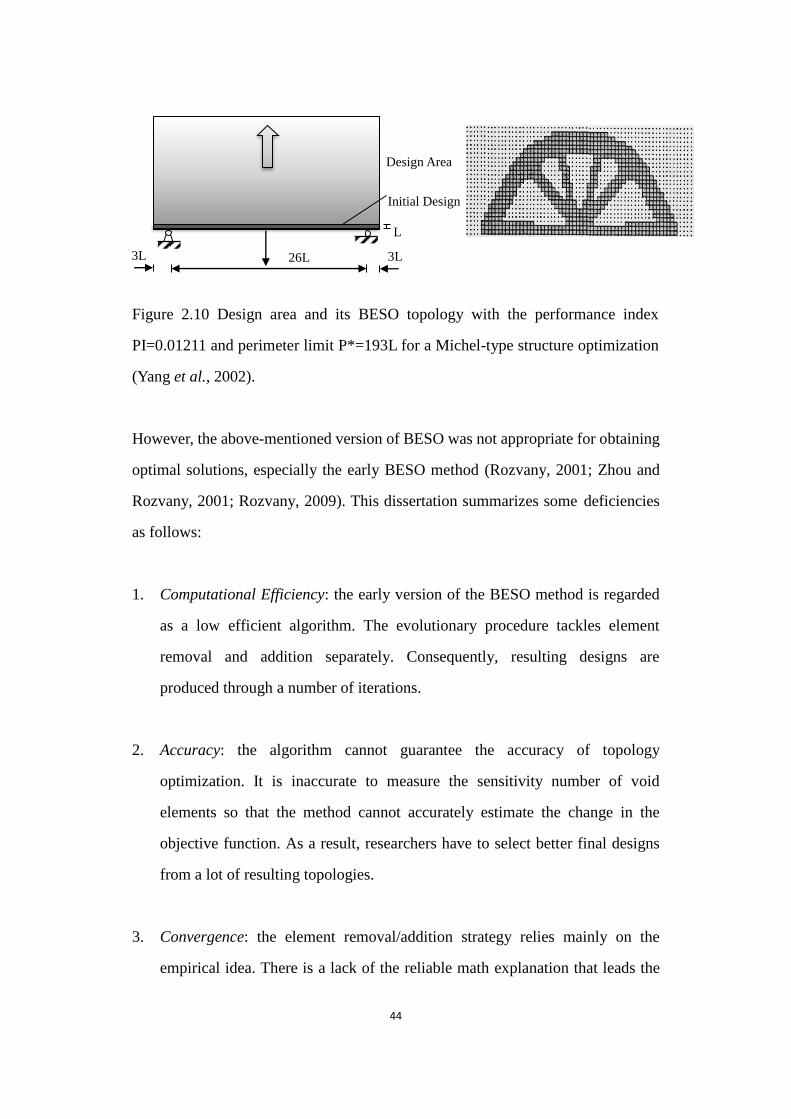
44
Figure 2.10 Design area and its ESO topology with the performance index PI=0.01211 and perimeter limit P*=193L for a Michel-type structure optimization
Figure 2.10 Design area and its BESO topology with the performance index
PI=0.01211 and perimeter limit P*=193L for a Michel-type structure optimization
(Yang et al., 2002).
However, the above-mentioned version of BESO was not appropriate for obtaining
optimal solutions, especially the early BESO method (Rozvany, 2001; Zhou and
Rozvany, 2001; Rozvany, 2009). This dissertation summarizes some deficiencies
as follows:
1. Computational Efficiency: the early version of the BESO method is regarded
as a low efficient algorithm. The evolutionary procedure tackles element
removal and addition separately. Consequently, resulting designs are
produced through a number of iterations.
2. Accuracy: the algorithm cannot guarantee the accuracy of topology
optimization. It is inaccurate to measure the sensitivity number of void
elements so that the method cannot accurately estimate the change in the
objective function. As a result, researchers have to select better final designs
from a lot of resulting topologies.
3. Convergence: the element removal/addition strategy relies mainly on the
empirical idea. There is a lack of the reliable math explanation that leads the
L
26L 3L 3L
Initial Design
Design Area
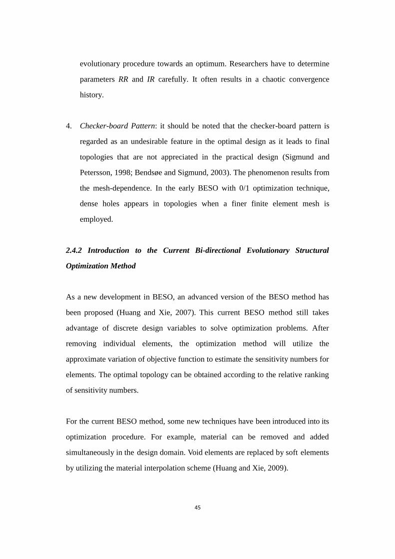
45
evolutionary procedure towards an optimum. Researchers have to determine
parameters RR and IR carefully. It often results in a chaotic convergence
history.
4. Checker-board Pattern: it should be noted that the checker-board pattern is
regarded as an undesirable feature in the optimal design as it leads to final
topologies that are not appreciated in the practical design (Sigmund and
Petersson, 1998; Bendsøe and Sigmund, 2003). The phenomenon results from
the mesh-dependence. In the early BESO with 0/1 optimization technique,
dense holes appears in topologies when a finer finite element mesh is
employed.
2.4.2 Introduction to the Current Bi-directional Evolutionary Structural
Optimization Method
As a new development in BESO, an advanced version of the BESO method has
been proposed (Huang and Xie, 2007). This current BESO method still takes
advantage of discrete design variables to solve optimization problems. After
removing individual elements, the optimization method will utilize the
approximate variation of objective function to estimate the sensitivity numbers for
elements. The optimal topology can be obtained according to the relative ranking
of sensitivity numbers.
For the current BESO method, some new techniques have been introduced into its
optimization procedure. For example, material can be removed and added
simultaneously in the design domain. Void elements are replaced by soft elements
by utilizing the material interpolation scheme (Huang and Xie, 2009).

46
In addition, the filter scheme was established as an effective mechanism for
extrapolating sensitivity numbers in the current BESO method (Huang and Xie,
2007). The so-called checkerboard pattern is the area where the density jumps
frequently from 0 (or xmin) to 1 between neighboring elements in a resulting
topology. Figure 2.11 is showing the typical checkerboard regions in a resulting
topology. It results from unreasonable numerical modeling (Díaz and Sigmund,
1995; Jog and Haber, 1996). The feature is also unexpected in industrial
manufacturing. Next, the mesh-dependency means that result solution varies
according to different finite element meshes. In fact, the finer the structure is
meshed, the better finite element modeling should be obtained (Sigmund and
Petersson, 1998).
Figure 2.11 Typical checkerboard regions in an optimum solution
Figure 2.11 Typical checkerboard regions in an optimum solution (Kim et al.,
2002)
In the current BESO method, the optimization technique utilizes a filter scheme to
prevent unstable phenomena such as checkerboard and mesh-dependency in
structural topology optimization (Huang and Xie, 2007). Element density can be
modified and becomes a function of its neighboring design variables. There are
several advantages for the current filter. Firstly, the technique can effectively
overcome numerical problems in topology optimization such as checkerboard and
mesh-dependency. Its effectiveness has been demonstrated in Figure 2.12 when
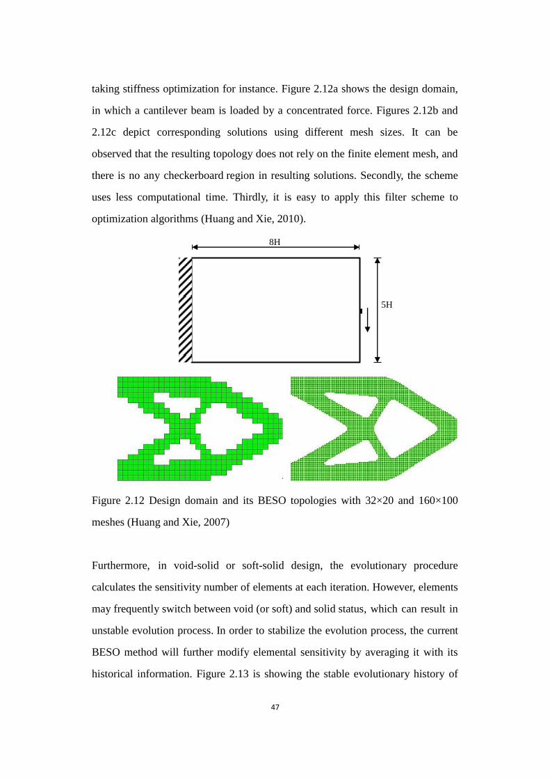
47
taking stiffness optimization for instance. Figure 2.12a shows the design domain,
in which a cantilever beam is loaded by a concentrated force. Figures 2.12b and
2.12c depict corresponding solutions using different mesh sizes. It can be
observed that the resulting topology does not rely on the finite element mesh, and
there is no any checkerboard region in resulting solutions. Secondly, the scheme
uses less computational time. Thirdly, it is easy to apply this filter scheme to
optimization algorithms (Huang and Xie, 2010).
Figure 2.12 Design domain and its BESO topologies with 32×20 and 160×100 meshes
Figure 2.12 Design domain and its BESO topologies with 32×20 and 160×100
meshes (Huang and Xie, 2007)
Furthermore, in void-solid or soft-solid design, the evolutionary procedure
calculates the sensitivity number of elements at each iteration. However, elements
may frequently switch between void (or soft) and solid status, which can result in
unstable evolution process. In order to stabilize the evolution process, the current
BESO method will further modify elemental sensitivity by averaging it with its
historical information. Figure 2.13 is showing the stable evolutionary history of
5H
8H
48
stiffness optimization for the above-mentioned cantilever while considering the
evolutionary stabilization. Both topology shape and structural compliance are
very stable after reaching the prescribed volume.
Figure 2.13 The evolutionary history of stiffness optimization for a cantilever
Figure 2.13 The evolutionary history of stiffness optimization for a cantilever
(Huang and Xie, 2007)
2.4.3 Hard-kill Based and Soft-kill Based Bi-directional Evolutionary Structural
Optimization Method
In topology optimization, the element should be seen as the design variable 𝑒
during the evolution procedure. There are two main types of approaches in the
current BESO method, namely the hard-kill and soft-kill BESO. For the hard-kill
based BESO, binary values 0 and 1 were designated to be the absence and presence
of an element respectively. That is, the hard-kill based BESO method can
completely remove ineffective elements in the design domain as opposed to the
density-based method. The method can reduce the computational time
considerably. This is because the removed elements will not be taken into
49
consideration in the finite element analysis, especially a great deal of removed
elements during the late period of the evolution process. However, it is possible
that really removing elements can result in inaccurate sensitivity calculation for
void elements.
Therefore, the soft elements with very low density were used to replace the void
elements in a Sequential Element Rejection and Admission method (Rozvany,
2009). As a result, the thickness problem appears in topology optimization. In 2009,
Huang and Xie proposed a soft-kill BESO method utilizing the material
interpolation scheme with penalization (Huang and Xie, 2009). In this method,
design variable 𝑒 is seen as the relative density of an element. Normally, a small
value of 𝑚𝑖𝑛 e.g. 0.001 is used to denote the void elements in the material
interpolation scheme. That means that the design variable 𝑒 change from 1 to
𝑚𝑖𝑛 for elements with lower sensitivity and from 𝑚𝑖𝑛 to 1 for elements with a
higher one during the evolution process. Elements with low sensitivity numbers
are not really removed from the design domain. This is the explicit characteristic
that distinguishes the soft-kill based BESO from the hard-kill based BESO.
In a word, the hard-kill BESO method can be seen as a special case of the soft-kill
BESO method (Huang and Xie, 2010). As low-density material can be really
removed in design domain, this optimization method is beneficial to overcome the
convergence difficulty caused by extreme deformation of low-density elements in
the large-displacement finite element analysis. Therefore, this dissertation will
present an optimization approach for designing geometrically nonlinear compliant
mechanisms with the aid of the hard-kill BESO method.
2.4.4 Applications of the Current Bi-directional Evolutionary Structural
Optimization Method
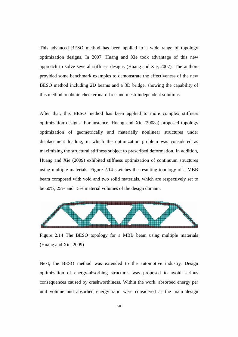
50
This advanced BESO method has been applied to a wide range of topology
optimization designs. In 2007, Huang and Xie took advantage of this new
approach to solve several stiffness designs (Huang and Xie, 2007). The authors
provided some benchmark examples to demonstrate the effectiveness of the new
BESO method including 2D beams and a 3D bridge, showing the capability of
this method to obtain checkerboard-free and mesh-independent solutions.
After that, this BESO method has been applied to more complex stiffness
optimization designs. For instance, Huang and Xie (2008a) proposed topology
optimization of geometrically and materially nonlinear structures under
displacement loading, in which the optimization problem was considered as
maximizing the structural stiffness subject to prescribed deformation. In addition,
Huang and Xie (2009) exhibited stiffness optimization of continuum structures
using multiple materials. Figure 2.14 sketches the resulting topology of a MBB
beam composed with void and two solid materials, which are respectively set to
be 60%, 25% and 15% material volumes of the design domain.
Figure 2.14 The BESO topology for a MBB beam using multiple materials
Figure 2.14 The BESO topology for a MBB beam using multiple materials
(Huang and Xie, 2009)
Next, the BESO method was extended to the automotive industry. Design
optimization of energy-absorbing structures was proposed to avoid serious
consequences caused by crashworthiness. Within the work, absorbed energy per
unit volume and absorbed energy ratio were considered as the main design

51
parameters. The adjoint method was then employed to derive the sensitivity
numbers (Huang et al., 2007).
In 2008, this advanced BESO technique was developed to solve an optimization
problem for periodic structures (Huang and Xie, 2008b). That work adopts a
certain quantity of unit cells in the design domain, and determines these cells on
basis of the element removal/addition strategy. In 2010, Huang et al. presented a
new BESO method for the topology optimization of vibrating continuum
structures (Huang et al., 2010). The optimization algorithm combined with a
modified SIMP model was used to avoid the artificial localized modes, and the
rigorous optimality criteria were addressed to satisfy a prescribed weight
constraint.
As for topology optimization of material microstructure, the current BESO
technique has also been exploited and developed for the topological design of
cellular and composite materials, considering a wide range of design objectives.
For example, Huang et al. (2011) described the optimal design of microstructures
of cellular materials for maximum bulk or shear modulus. In 2012, Huang et al.
achieved the topology optimization of periodic composites for external magnetic
permeability and electrical permittivity (Huang et al., 2012). The design
objectives aim to search for maximizing magnetic permeability, maximizing
electrical permittivity, and maximizing or minimizing a combination of the above
properties.
So far, it has been demonstrated that the current BESO method is capable of
generating reliable and practical topologies with high computational efficiency for
various optimization problems. It is worthwhile to extend the BESO method to
optimizing compliant mechanisms. Therefore, this dissertation will adopt and
52
modify the advanced BESO method for the optimal design of compliant
mechanisms.
2.4.5 Summary of the Bi-directional Evolutionary Structural Optimization
Method
This chapter has reviewed the BESO method. In the current BESO method, a filter
scheme is introduced to prevent checkerboard and mesh-dependency. Averaging
the sensitivity number is used to improve the convergence histories of topology
optimization.
This advanced BESO method makes up effectively for the deficiencies of the ESO
and the early BESO methods. Firstly, the current BESO method can achieve
structural optimums based on any possible initial design domain (Huang et al.,
2007). Secondly, this optimization method saves significant computational time.
Thirdly, its evaluation procedure is more robust when compared to the ESO and
initial BESO methods affected significantly by parameters. Fourthly, the current
BESO method is capable of generating reliable and practical topologies for more
optimization design problems. Fifthly, the new BESO procedure can obtain clear
resulting topologies so that final designs are easily measured and manufactured in
the industry (Huang et al., 2007).
Overall, this new BESO reduces computational time significantly. Resulting
topologies have also demonstrated that the current BESO method is capable of
generating reliable and practical topologies with high computational efficiency for
various optimization design problems (Huang and Xie, 2007; Huang and Xie,
2008b). Thus it is worthwhile to take the BESO method into consideration in the
optimal design of compliant mechanisms.
53
2.5 General Remarks
This chapter has reviewed previous research of designing compliant mechanisms
based on both the kinematics-based approach and the structural optimization-based
approach. As continuum-based models reflect the real artifact more closely, there
is a large emphasis on the description and discussion of topology optimization of
compliant mechanisms on the basis of various optimization-based methods. As
previous designs have shown, several deficiencies have been summarized in this
chapter such as vague resulting topologies of compliant mechanisms, structural
connectivity problems, unreasonable constraints cited in optimization algorithms
and the control of hinge regions in topologies.
In addition, this chapter also reviewed some topology optimization methods and
introduced fundamental theories of the BESO method. It has been proved that the
current BESO method is capable of generating reliable and practical topologies
with high computational efficiency for various optimization design problems. Thus,
it is worthwhile to extend the BESO method to the optimal design of compliant
mechanisms. However, the discrete material distribution pattern often results in an
ill-posed problem so that the current BESO method cannot be directly applied to
the optimal design of compliant mechanisms.
Therefore, this dissertation aims to propose a modified BESO method for topology
optimization of compliant mechanisms. To achieve the goal, several efforts will be
made in this work:
• Firstly, this research will first introduce the BESO method into the systematic
design field of compliant mechanisms. The traditional BESO procedure will
54
be revolutionized by eliminating the binary material distribution theory and
introducing intermediate densities. This modified BESO method will be
beneficial to accurately capture the change of design variables for topology
optimization of compliant mechanisms.
• Secondly, this dissertation will establish new computational algorithms for
optimal design of compliant mechanisms. Compliance constraints are used to
effectively control the energy stored in compliant mechanisms with linear or
geometrically nonlinear behaviors after loading. These new optimization
algorithms will benefit in producing a series of optimal solutions with the
balance of the flexibility and stiffness necessities. In addition, a new objective
optimization will be modeled by considering desirable displacement and
simultaneously precluding the formation of hinges in order to design
hinge-free compliant mechanisms.
• Thirdly, nonlinear analysis procedures of compliant mechanisms will be
incorporated into the topology synthesis of compliant mechanisms as linear
analysis is inaccurate in modeling large deformation.
• Fourthly, this dissertation will exhibit a number of 2D and 3D numerical
examples to verify the proposed optimization techniques and demonstrate the
effectiveness of presented methods for compliant mechanism designs, such as
hinge-free and nonlinear compliant mechanisms.
• Fifthly, developed techniques will be shown to be suitable for industrial
applications. The technique involved in the control of hinge regions will help
mechanism designs reduce stress concentration and fatigue breakage. Clear
resulting mechanism topologies generated here will be more acceptable for
55
industrial manufacturability. In addition, the optimal design of nonlinear
compliant mechanisms will be performed for real applications as the
simulation is more accurate.
References
Allaire, G., Jouve, F. and Toader, A.-M., 2002, "A level-set method for shape optimization",
Comptes Rendus Mathematique 334(12), 1125-1130.
Allaire, G., Jouve, F. and Toader, A.-M., 2004, "Structural optimization using sensitivity analysis
and a level-set method", Journal of Computational Physics 194(1), 363-393.
Allaire, G., Jouve, F. and Toader, A.-M., 2004, "Structural optimization using sensitivity analysis
and a level-set method ", Journal of Computational Physics 194(1), 363-393.
Ananthasuresh, G. K., 1994. A new design paradigm for micro-electro-mechanical systems and
investigations on the compliant mechanism sythesis, University of Michigan,
Ananthasuresh, G. K. and Howell, L. L., 1996. Case studies and a note on the degrees-of-freedom in
compliant mechanisms ASME Design Engineering Technical Conferences and Computers
in Engineering Conference.
Ananthasuresh, G. K., Kota, S. and Gianchandani, Y., 1993. Systematic synthesis of micro
compliant mechanisms - preliminary results. Proceeding of 3rd National Applied
Mechanisms and Robotics.
Ananthasuresh, G. K., Kota, S. and Kikuchi, N., 1994. Strategies for systematic synthesis of
compliant MEMS. 1994 ASME Winter Annual Meeting Chicago.
Ansola, R., Veguería, E. and Canales, J., 2010, "An element addition strategy for thermally actuated
compliant mechanism topology optimization, Engineering Computations", Engineering
Computations 27(6), 694-711.
Ansola, R., Veguería, E., Canales, J. and Tárrago, J. A., 2007, "A simple evolutionary topology
optimization procedure for compliant mechanism design ", Finite Elements in Analysis and
Design 44(1-2), 53-62.
56
Ansola, R., Veguería, E., Maturana, A. and Canales, J., 2010, "3D compliant mechanisms synthesis
by a finite element addition procedure", Finite Elements in Analysis and Design 46(9),
760-769.
Barnett, R. L., 1966, "Survey of optimum structural design", Experimental Mechanics 6(12),
19A-26A.
Belytschko, T., Xiao, S. P. and Parimi, C., 2003, "Topology optimization with implicit functions and
regularization", International Journal for Numerical Methods in Engineering 57(8),
1177-1196.
Bendsøe, M. P., 1989, "Optimal shape design as a material distribution problem", Structural
Optimization 1(4), 193-202.
Bendsøe, M. P. and Kikuchi, N., 1988, "Generating optimal topologies in structural design using a
homogenization method ", Computer Methods in Applied Mechanics and Engineering
71(2), 197-224.
Bendsøe, M. P. and Sigmund, O., 1999, "Material interpolation schemes in topology optimization",
Archive of Applied Mechanics 69, 635-654.
Bendsøe, M. P. and Sigmund, O., 2003. Topology Optimization. Theory, Methods and Applications,
Springer, Berlin.
Bruns, T. and Tortorelli, D., 1998. Topology optimization of geometrically nonlinear structures and
compliant mechanisms. 7th symposium on Multidisplinary Analysis and Optimization.
Bruns, T. E. and Tortorelli, D. A., 2001, "Topology optimization of non-linear elastic structures and
compliant mechanisms", Computer Methods in Applied Mechanics and Engineering
190(26-27), 3443-3459.
Burns, R. H. and Crossley, F. R. E., 1966, "Structural Permutations of Flexible Link Mechanisms",
ASME Paper 66-Mech-5.
Burns, R. H. and Crossley, F. R. E., 1968, "Kinetostatic Synthesis of Flexible Link Mechanisms",
ASME Paper 68-Mech-36.
Chapman, C. D. and Jakiela, M. J., 1996, "Genetic algorithm-based structural topology design with
compliance and topology simplification considerations", ASME Journal of Mechanical

57
Design 118(1), 89-98.
Chapman, C. D., Saitou, K. and Jakiela, M. J., 1994, "Genetic algorithms as an approach to
configuration and topology design ", Journal of Mechanical Design 116(4), 1005-1012.
Cheng, K. T. and Olhoff, N., 1981, "An investigation concerning optimal design of solid elastic
plates", International Journal of Solids and Structures 17(3), 305-323.
Chu, D. N., Xie, Y. M., Hira, A. and Steven, G. P., 1996, "Evolutionary structural optimization for
problems with stiffness constraints", Finite Elements in Analysis and Design 21(4),
239-251.
Díaz, A. and Sigmund, O., 1995, "Checkerboard patterns in layout optimization", Structural
optimization 10(1), 40-45.
Dhingra, A. K. and Bennage, W. A., 1995, "Topological optimization of truss structures using
simulated annealing", Engineering Optimization 24(4), 239-259.
Dijk, N. P. v., Yoon, G. H., Keulen, F. v. and Langelaar, M., 2010, "A level-set based topology
optimization using the element connectivity parameterization method", Structural and
Multidisciplinary Optimization 42(2), 269-282.
Du, Y., Chen, L. and Luo, Z., 2008, "Topology synthesis of geometrically nonlinear compliant
mechanisms using meshless methods ", Acta Mechanica Solida Sinica 21(1), 51-61.
Edwards, B. T., Jensen, B. D. and Howell, L. L., 1999. A pseudo-rigid-body model for functionally
binary pinned-pinned segments used in compliant mechanisms. the 1999 ASME Design
Engineering Technical Conferences, Las Vegas.
Feng, Z., Yu, Y. and Wang, W., 2010, "Modeling of large-deflection links for compliant
mechanisms", Frontiers of Mechanical Engineering in China 5(3), 294-301.
Frecker, M. I., Ananthasuresh, G. K., Nishiwaka, S., Kikuchi, N. and Kota, S., 1997, "Topological
Synthesis of Compliant Mechanisms Using Multi-Criteria Optimization", Journal of
Mechanical Design 119(2), 238-245.
Goldberg, D. E., 1989. Genetic algorithms in search, optimization, and machine learning,
Addison-Wesley, Boston.
Haber, E., 2004, "A multilevel, level-set method for optimizing eigenvalues in shape design
58
problems", Journal of Computational Physics 198(2), 518-534.
Hajela, P. and Lee, E., 1995, "Genetic algorithms in truss topological optimization", International
Journal of Solids and Structures 32(22), 3341-3357.
Hemp, W. S., 1973. Optimum Structures, Oxford University Press, England.
Her, I. and Midha, A., 1987, "A compliance number concept for compliant mechanisms, and type
synthesis", Journal of Mechanisms, Transmissions, and Automation in Design 109(3),
348-355.
Her, I., Midha, A. and Salamon, B. A., 1992. A methodology for compliant mechanisms design: Part
II - shooting method and application. Proceedings of the 18th ASME Design Automation
Conference: Advances in Design Automation.
Hill, T. C. and Midha, A., 1990, "A graphical, user-driven newton-raphson technique for use in the
analysis and design of compliant mechanisms", Journal of Mechanical Design 112(1),
123-130.
Holland, J. H., 1975. Adaptation in Natural and Artificial Systems, The University of Michigan
Press, Ann Arbor.
Howell, L. L., 2001. Compliant Mechanisms, John Wiley & Sons, New York.
Howell, L. L. and Midha, A., 1994, "A method for the design of compliant mechanisms with
small-length flexural pivots", Journal of Engineering Design 116(1), 280-289.
Howell, L. L. and Midha, A., 1995, "Parametric deflection approximations for end-loaded,
large-deflection beams in compliant mechanisms", Journal of Mechanical Design 117(1),
156-165.
Howell, L. L. and Midha, A., 1996a, "A loop-closure theory for the analysis and synthesis of
compliant mechanisms", Journal of Mechanical Design 118(1), 121-125.
Howell, L. L. and Midha, A., 1996b. Parametric deflection approximations for initially curved,
large-deflection beams in compliant mechanisms Proceedings of the 1996 ASME Design
Engineering Technical Conferences, Irvine.
Huang, X., Radman, A. and Xie, Y. M., 2011, "Topological design of microstructures of cellular
materials for maximum bulk or shear modulus", Computational Materials Science 50(6),
59
1861-1870.
Huang, X. and Xie, Y. M., 2007, "Convergent and mesh-independent solutions for the bi-directional
evolutionary structural optimization method", Finite Elements in Analysis and Design
43(14), 1039-1049.
Huang, X. and Xie, Y. M., 2008a, "Topology optimization of nonlinear structures under
displacement loading", Engineering Structures 30(7), 2057-2068.
Huang, X. and Xie, Y. M., 2008b, "Optimal design of periodic structures using evolutionary
topology optimization", Structural and Multidisciplinary Optimization 36(6), 597-606.
Huang, X. and Xie, Y. M., 2009, "Bi-directional evolutionary topology optimization of continuum
structures with one or multiple materials ", Computational Mechanics 43(3), 393-401.
Huang, X. and Xie, Y. M., 2010. Evolutionary Topology Optimization of Continuum Structures :
Methods and Applications, John Wiley & Sons, Chichester.
Huang, X., Xie, Y. M. and Burry, M. C., 2007, "Advantages of Bi-Directional Evolutionary
Structural Optimization (BESO) over Evolutionary Structural Optimization (ESO)",
Advances in Structural Engineering 10(6), 727-737.
Huang, X., Xie, Y. M., Jia, B., Li, Q. and Zhou, S. W., 2012, "Evolutionary topology optimization of
periodic composites for extremal magnetic permeability and electrical permittivity",
Structural and Multidisciplinary Optimization 46(3), 385-398.
Huang, X., Xie, Y. M. and Lu, G., 2007, "Topology optimization of energy-absorbing structures",
International Journal of Crashworthiness 12(6), 663-675.
Huang, X., Zuo, Z. H. and Xie, Y. M., 2010, "Evolutionary topological optimization of vibrating
continuum structures for natural frequencies", Computers and Structures 88(5-6), 357-364.
Jog, C. S. and Haber, R. B., 1996, "Stability of finite element models for distributed-parameter
optimization and topology design", Computer Methods in Applied Mechanics and
Engineering 130(3-4), 203-226.
Jouve, F. and Mechkour, H., 2008, "Level set based method for design of compliant mechanisms",
European Journal of Computational Mechanics 17(5-7), 957-971.
Kikuchi, N., Nishiwaki, S., Fonseca, J. S. O. and Silva, E. C. N., 1998, "Design optimization method
60
for compliant mechanisms and material microstructure ", Computer Methods in Applied
Mechanics and Engineering 151(3-4), 401-417.
Kim, H., Querin, O. M. and Steven, G. P., 2002, "On the development of structural optimisation and
its relevance in engineering design", Design Studies 23(1), 85-102.
Kohn, R. V. and Strang, G., 1986, "Optimal design and relaxation of variational problems",
Communications on Pure and Applied Mathematics 39, 1-25 139-182 353-377.
Larsen, U. D., Signund, O. and Bouwsta, S., 1997, "Design and fabrication of compliant
micromechanisms and structures with negative Poisson's ratio", Journal of
Microelectromechanical Systems 6(2), 99-106.
Lau, G. K., Du, H. and Lim, M. K., 2001, "Use of functional specifications as objective functions in
topological optimization of compliant mechanism", Computer Methods in Applied
Mechanics and Engineering 190(34), 4421-4433.
Levy, R. and Lev, O. E., 1987, "Recent developments in structural optimization", Journal of
Structural Engineering 113(9), 1939-1962.
Li, Q., Steven, G. P., Querin, O. M. and Xie, Y. M., 1997. Optimal shape design for steady heat
conduction by the evolutionary procedure. Proceedings of 1997 ASME National Hear
Transfer Conference, Baltimore, USA.
Li, Q., Steven, G. P. and Xie, Y. M., 2001, "A simple checkerboard suppression algorithm for
evolutionary structural optimization", Structural and Multidisciplinary Optimization 22(3),
230-239.
Li, W., Li, Q., Steven, G. P. and Xie, Y. M., 2005, "An evolutionary shape optimization for elastic
contact problems subject to multiple load cases", Computer Methods in Applied Mechanics
and Engineering 194(30-33), 3394-3415.
Lin, J., Luo, Z. and Tong, L., 2010, "A new multi-objective programming scheme for topology
optimization of compliant mechanisms", Structural and Multidisciplinary Optimization
40(1-6), 241-255.
Luo, J., Luo, Z., Chen, S., Tong, L. and Wang, M. Y., 2008, "A new level set method for systematic
design of hinge-free compliant mechanisms", Computer Methods in Applied Mechanics

61
and Engineering 198(2), 318-331.
Luo, Z., Chen, L., Yang, J., Zhang, Y. and Abdel-Malek, K., 2005, "Compliant mechanism design
using multi-objective topology optimization scheme of continuum structures", Structural
and Multidisciplinary Optimization 30(2), 142-154.
Luo, Z. and Tong, L., 2008, "A level set method for shape and topology optimization of
large-displacement compliant mechanisms", International Journal for Numerical Methods
in Engineering 76(6), 862-892.
Luo, Z., Tong, L. and Wang, M. Y., 2008, "Design of distributed compliant micromechanisms with
an implicit free boundary representation", Structural and Multidisciplinary Optimization
36(6), 607-621.
Luo, Z., Tong, L., Wang, M. Y. and Wang, s., 2007, "Shape and topology optimization of compliant
mechanisms using a parameterization level set method", Journal of Computational Physics
227(1), 680-705.
Metropolis, N., Rosenbluth, A. W., Rosenbluth, M. N., Teller, A. H. and Teller, E., 1953, " Equation
of state calculations by fast computing machines", The Journal of Chemical Physics 21(6),
1087-1092.
Mettlach, G. A. and Midha, A., 1996, Using Burmester theory in the design of compliant
mechanisms, ASME Design Engineering Technical Conferences and Computers in
Engineering Conference,
Michell, A. G. M., 1904, "The limits of economy of materials in frame structures", Philosophy
Magazine 8(47), 589-597.
Midha, A., Her, I. and Salamon, B., 1992, A methodology for compliant mechanisms design: Part I-
introduction and large-deflection analysis, 18 th Annual ASME Design Automation
Midha, A., Norton, T. W. and Howell, L. L., 1992a, On the nomenclature and classification of
compliant mechanisms: abstractions of mechanisms and mechanism synthesis problems,
ASME 1992 Design Technical Conferences, 22nd Biennial Mechanisms Conference,
Flexible Mechanisms, Dynamics, and Analysis, Scottsdale, Arizona.
Midha, A., Norton, T. W. and Howell, L. L., 1992b, On the nomenclature and classification of

62
compliant mechanisms: the components of mechanisms, ASME 1992 Design Technical
Conferences, 22nd Biennial Mechanisms Conference, Flexible Mechanisms, Dynamics,
and Analysis, Scottsdale, Arizona.
Midha, A., Norton, T. W. and Howell, L. L., 1994, "On the nomenclature, classification, and
abstractions of compliant mechanisms", Journal of Mechanical Design 116(1), 270-279.
Murphy, M. D., Midha, A. and Howell, L. L., 1994, On the Mobility of Compliant Mechanism,
Proceedings of the 1994 ASME Mechanisms Conference,
Murphy, M. D., Midha, A. and Howell, L. L., 1996, "The topological synthesis of compliant
mechanisms", Mechanism and Machine Theory 31(2), 185-199.
Nishiwaki, S., Frecker, M. I., Min, S. and Kikuchi, N., 1998, "Topology optimisation of compliant
mechanisms using the homogenization method", International Journal for Numerical
Methods in Engineering 42(3), 535-559.
Ohsaki, M., 1995, "Genetic algorithm for topology optimization of trusses", Computers and
Structures 57(2), 219-225.
Otomori, M., Yamada, K. I. and Nishiwaki, S., 2011, "Level set-based topology optimisation of a
compliant mechanism design using mathematical programming", Mechanical Sciences 2,
91-98.
Paros, J. M. and Weisbord, L., 1965. How to design flexural hinges. Machine Design. November 25,
1965: 151-156.
Parsons, R. and Canfield, S. L., 2002, "Developing genetic programming techniques for the design
of compliant mechanisms", Structural and Multidisciplinary Optimization 24(1), 78-86.
Pedersen, C. B. W., Buhl, T. and Sigmund, O., 2001, "Topology synthesis of large-displacement
compliant mechanisms", International Journal for Numerical Methods in Engineering
50(12), 2683-2705.
Prager, W., 1970, "Optimization of structural design", Journal of Optimization Theory and
Applications 6(1), 1-21.
Prager, W., 1977, "Optimal layout of cantilever trusses", Journal of Optimization Theory and
Applications 23(1), 111-117.
63
Querin, O. M., Steven, G. P. and Xie, Y. M., 1996. Topology optimisation of structures with material
and geometric nonlinearities. Proc. 6-th AIAA/USAF/NASA/ISSMO Symposium on
Multidisciplinary Analysis and Optimization, Bellevue Washington, USA.
Querin, O. M., Steven, G. P. and Xie, Y. M., 1998, "Evolutionary structural optimisation (ESO)
using a bidirectional algorithm", Engineering Computations 15(8), 1031-1048.
Querin, O. M., Young, V., Steven, G. P. and Xie, Y. M., 2000, "Computational e.ciency and
validation of bi-directional evolutionary structural optimisation", Computer Methods in
Applied Mechanics and Engineering 189(2), 559-573.
Rajan, S. D., 1995, "Sizing, shape, and topology design optimization of trusses using genetic
algorithm", Journal of Structural Engineering 121(10), 1480-1487.
Rodriguez- Velazquez, J. and Seireg, A. A., 1985, "Optimizing the shapes of structures via a
rule-based computer program", Computing in Mechanical Engineering 4(1), 20-28.
Rozvany, G. I. N., 2001, "Stress ratio and compliance based methods in topology optimization - a
critical review", Structural and Multidisciplinary Optimization 21(2), 109-119.
Rozvany, G. I. N., 2009, "A critical review of established methods of structural topology
optimization", Structural and Multidisciplinary Optimization 37(3), 217-237.
Rozvany, G. I. N., Bendsøe, M. P. and Kirsch, U., 1995, "Layout Optimization of Structures",
Applied Mechanics Reviews 48(2), 41-119.
Rozvany, G. I. N., Ong, T. G., Szeto, W. T., Sandler, R., Olhoff, N. and Bendsøe, M. P., 1987,
"Least-weight design of perforated elastic plates", International Journal of Solids and
Structures 23, 521-536 537-550.
Salamon, B. A. and Midha, A., 1992. An introduction to mechanical advantage in compliant
mechanisms. Proceedings of the 18th ASME Design Automation Conference: Advances in
Design Automation.
Salamon, B. A. and Midha, A., 1998, "An introduction to mechanical advantage in compliant
mechanisms", Journal of mechanical design 120(2), 311-315.
Saxena, A., 2002, On multiple-material optimal compliant topologies: discrete variable
parameterization using genetic algorithm, ASME 2002 International Design Engineering

64
Technical Conferences and Computers and Information in Engineering Conference,
Montreal.
Saxena, A., 2005, "Topology design of large displacement compliant mechanisms with multiple
materials and multiple output ports", Structural and Multidisciplinary Optimization 30,
477-490.
Sethian, J. A. and Wiegmann, A., 2000, "Structural boundary design via level set and immersed
interface methods ", Journal of Computational Physics 163(2), 489-528.
Shim, P. Y. and Manoochehri, S., 1997, "Generating optimal configurations in structural design
using simulated annealing", International Journal for Numerical Methods in Engineering
40(6), 1053-1069.
Sigmund, O., 1994, "Materials with prescribed constitutive parameters: An inverse homogenization
problem", International Journal of Solids and Structures 31(17), 2313-2329.
Sigmund, O., 1997, "On the design of compliant mechanisms using topology optimization",
Mechanics of Structures and Machines 25(4), 493-524.
Sigmund, O., 2001, "Design of multiphysics actuators using topology optimization - Part I:
One-material structures", Computer Methods in Applied Mechanics and Engineering
190(49-50), 6577-6604.
Sigmund, O. and Petersson, J., 1998, "Numerical instabilities in topology optimization: A survey on
procedures dealing with checkerboards, mesh-dependencies and local minima", Structural
optimization 16(1), 68-75.
Takezawa, A., Nishiwaki, S. and Kitamura, M., 2010, "Shape and topology optimization based on
the phase field method and sensitivity analysis", Journal of Computational Physics 229(7),
2697-2718.
Topping, B. H. V., 1983, "Shape optimization of skeletal structures: a review", Journal of Structural
Engineering 109(8), 1933-1951.
Topping, B. H. V., Khan, A. I. and Leite, J. P. D. B., 1996, "Topological design of truss structures
using simulated annealing", Structural Engineering Review 8(2-3), 301-304.
Veguería, E., Ansola, R., Maturana, A. and Canales, J., 2008. Topology synthesis of compliant

65
mechanisms using an evolutionary method. International Conference on Engineering
Optimization, Rio de Janeiro, Brazil.
Wang, M. Y., 2009, "Mechanical and geometric advantages in compliant mechanism optimization",
Frontiers of Mechanical Engineering in China 4(3), 229-241.
Wang, M. Y., Chen, S., Wang, X. and Mei, Y., 2005, "Design of multimaterial compliant
mechanisms using level-set methods", Journal of mechanical design 127(5), 941-956.
Wang, M. Y., Wang, X. and Guo, D., 2003, "A level set method for structural topology optimization",
Computer Methods in Applied Mechanics and Engineering 192(1-2), 227-246.
Wang, S. and Wang, M. Y., 2006, "Radial basis functions and level set method for structural
topology optimization", International Journal for Numerical Methods in Engineering
65(12), 2060-2090.
Xie, Y. M. and Steven, G. P., 1992, Shape and layout optimisation via an evolutionary procedure,
Proceedings of International Conference on Computational Engingeering Science, Hong
Kong University of Science and Technology, Hong Kong.
Xie, Y. M. and Steven, G. P., 1993, "A simple evolutionary procedure for structural optimization ",
Computers and Structures 49(5), 885-896.
Xie, Y. M. and Steven, G. P., 1996, "Evolutionary structural optimization for dynamic problems",
Computers and Structures 58(6), 1067-1073.
Xie, Y. M. and Steven, G. P., 1997. Evolutionary Structural Optimization, Springer, London.
Yamada, T., Izui, K., Nishiwaki, S. and Takezawa, A., 2010, "A topology optimization method
based on the level set method incorporating a fictitious interface energy", Computer
Methods in Applied Mechanics and Engineering 199(45-48), 2876-2891.
Yang, X. Y., Xie, Y. M., Liu, J. S., Parks, G. T. and Clarkson, P. J., 2002, "Perimeter control in the
bidirectional evolutionary optimization method", Structural and Multidisciplinary
Optimization 24(6), 430-440.
Yang, X. Y., Xie, Y. M., Steven, G. P. and Querin, O. M., 1998. Bidirectional evolutionary method
for frequency optimization. Proceedings of the Seventh AIAA/USAF/NASA/ISSMO
Symposium on Multidiscriplinary Analysis and Optimization, St. Louis, USA.

66
Yang, X. Y., Xie, Y. M., Steven, G. P. and Querin, O. M., 1999, "Bidirectional evolutionary method
for stiffness optimization", AIAA Journal 37(11), 1483-1488.
Yoon, G. H. and Kim, Y. Y., 2005, "Element connectivity parameterization for topology
optimization of geometrically nonlinear structures", International Journal of Solids and
Structures 42(7), 1983-2009.
Yu, Y.-Q., Howell, L. L., Yue, Y., He, M.-G. and Lusk, C., 2005, "Dynamic modeling of compliant
mechanisms based on the pseudo-rigid-body model", Journal of Mechanical Design 127(4),
760-765.
Zhao, C., Steven, G. P. and Xie, Y. M., 1997, "Evolutionary natural frequency optimization of
two-dimensional structures with additional non-structural lumped masses", Engineering
Computations 14(2), 233-251.
Zhou, M. and Rozvany, G. I. N., 1991, "The COC algorithm, Part II: Topological, geometrical and
generalized shape optimization ", Computer Methods in Applied Mechanics and
Engineering 89(1-3), 309-336.
Zhou, M. and Rozvany, G. I. N., 2001, "On the validity of ESO type methods in topology
optimization", Structural and Multidisciplinary Optimization 21(1), 80-83.
Zhu, B. and Zhang, X., 2012, "A new level set method for topology optimization of distributed
compliant mechanisms", International Journal for Numerical Methods in Engineering
91(8), 843-871.
Zhu, B., Zhang, X. and Wang, N., 2013, "Topology optimization of hinge-free compliant
mechanisms with multiple outputs using level set method", Structural and
Multidisciplinary Optimization 47(5), 659-672.
Zhu, J. H., Zhang, W. H. and Qiu, K. P., 2007, "Bidirectional evolutionary topology optimization
using element replaceable method", Computational Mechanics 40(1), 97-109.

67
Chapter 3
Modified Bi-directional Evolutionary
Structural Optimization
68
Chapter Overview
To design ideal compliant mechanisms, flexibility should be considered in the
created compliant mechanisms. As a result, the optimal design of compliant
mechanisms can be quite sensitive to the classical removal/addition criterion of the
BESO method so that topology optimization may result in an ill-posed problem.
The traditional BESO method cannot be directly applied to the compliant
mechanism design. Therefore, this research presents the modified BESO method
using different volume constraints for designing compliant mechanisms. This
chapter first introduces its basic ideas and explains relative techniques. Then
numerical examples are provided to demonstrate capability and effectiveness of
solving optimization design problems.
3.1 Problem Statement
To seek optimums with a given volume of material, the BESO method formulates a
general optimization problem as follow:
Minimize ( ) = 𝐇( 1, 2, 3, … , 𝑛) (3.1)
Subject to: 𝑉∗ − ∑ 𝑉𝑒𝑁𝑒=1 𝑒 = 0
where h(x) denotes the objective function of the optimization problem. H is defined
as an n-dimension function. In addition, 𝑉𝑒 and 𝑉∗ represent respectively the
volumes for an individual element and the prescribed total structure in the volume
constraint. Design variable 𝑒 can be equal to 1 for solid element in the
traditional BESO method. Otherwise, 𝑒 will be set as 0 in solid-void design or
𝑚𝑖𝑛 in solid-soft design.
69
For the optimal design of compliant mechanisms, optimization techniques
naturally lead to the introduction of de facto hinges into final topologies. To ensure
structural continuity of compliant mechanisms, this research employs
intermediate densities to modify the traditional BESO method for optimizing
compliant mechanisms. Specifically, the optimal design can be viewed as the
special continuum containing m types of materials. Their corresponding density
variables of eth element can be defined as 0 ≤ 𝑒,𝑚 < 𝑒,𝑚−1 < ⋯ < 𝑒,𝑗 < ⋯ <
𝑒,2 < 𝑒,1 ≤ 1 when introducing intermediate densities in the interval [ 𝑒,𝑚, 1].
𝑒,𝑚 is defined as the density of soft elements 𝑚𝑖𝑛 . 𝑒,1 and 𝑒,𝑚−1 donate
upper and lower densities of solid elements respectively. Therefore, Design
variable 𝑒 is equal to 𝑒,1, 𝑒,2, … , 𝑒,𝑚−1 𝑜𝑟 𝑒,𝑚 in the modified BESO
method.
3.2 Sensitivity Calculation
The sensitivity from elements denotes the gradient of the objective function. It aims
to measure the changing trend owing to the small change in the design variable
when the whole design domain is meshed with finite elements. Generally, the
calculation can be written as Equation 3.2 by differentiating its objective function
𝛼𝑖 =𝜕ℎ(𝑥)
𝜕𝑥𝑒=𝜕𝐇(𝑥1,𝑥2,𝑥3,…,𝑥𝑛)
𝜕𝑥𝑒 (3.2)
When the eth element is completely removed from a design domain meshed
uniformly, the sensitivity number can estimate the change of the corresponding
design objective and can be expressed as Equation 3.3.
𝛼𝑒 = ∆𝑒 (3.3)
70
For the SIMP model, intermediate designs are penalized by using a constant
penalty in a matrix of constants of elasticity in Hooke‟ law, as shown in Equation
3.4 (Bendsøe and Sigmund, 2003).
=𝑥𝑒𝑝
1− 2[
1 0 1 0
0 01−
2
] (3.4)
The effective Young‟s modulus can be formulated as a function of 𝑒 for different
values of p, namely 𝑒𝑝𝐸 . For each element, the density of material varies
continuously between 0 and 1. The elastic properties for intermediate densities can
be determined according to the density using a power-law interpolation which leads
to nearly 0/1 optimum solution during the evolutionary process (Rietz, 2001).
In the traditional BESO method, Young‟s modulus can be interpolated as the
function with the density variable as 𝐸( 𝑒) = 𝑒𝑝𝐸1 according to the above
solid-void design principle, where 𝐸1 denotes Young‟s modulus for solid material
and the power p is referred to as the penalty exponent. After meshing the whole
design domain, the stiffness matrix K can be expressed by the elemental stiffness
matrix and design variables as = ∑ 𝑒𝑝 𝑒
1𝑒 , in which 𝑒
1 represents the element
stiffness matrix for solid elements.
As described in the previous literature (Huang and Xie, 2010), it is supposed that
the soft-kill method is employed to solve the stiffness design problem. The
sensitivity of the mean compliance can be simply expressed at two types of
elemental levels, solid and soft elements, by introducing this material interpolation
scheme. (Huang and Xie, 2010b)

71
𝜕𝐶
𝜕𝑥𝑒= {
−𝑝𝐮𝑒𝑇 𝑒
1𝐮𝑒 2⁄ 𝑤𝑒𝑛 𝑒 = 1
−𝑝 𝑚𝑖𝑛𝑝−1𝐮𝑒
𝑇 𝑒1𝐮𝑒 2⁄ 𝑤𝑒𝑛 𝑒 = 𝑚𝑖𝑛
(3.5)
In the modified BESO method, the interpolation function, which addresses
intermediate densities, can be expressed as 𝐸( 𝑒,𝑗) = ( 𝑒,𝑗 𝑒,0⁄ )𝑝𝐸0, where 𝑒,0
and 𝐸0 are respectively the base density and base Young‟s modulus in the initial
design domain. The global stiffness matrix can be written as
= ∑ ( 𝑒,𝑗 𝑒,0⁄ )𝑝 𝑒0
𝑒 using an initial element stiffness matrix. It can be noted
that the design problem is including a unique constraint 𝑉∗ = ∑ 𝑉𝑒 𝑒 ( 𝑒 =𝑛𝑒=1
𝑒,1, 𝑒,2, … , 𝑜𝑟 𝑒,𝑚).
Here the stiffness design is still cited to demonstrate the sensitivity calculation in
the modified BESO method. The sensitivity of the mean compliance can be
expressed at all elemental levels including solid and soft elements as
𝜕𝐶
𝜕𝑥𝑒= −𝑝 𝑒
𝑝−1𝐮𝑒𝑇 𝑒
0𝐮𝑒 (2 0𝑝)⁄ 𝑤𝑒𝑛 𝑒 = 𝑒,1, 𝑒,2, … , 𝑒,𝑚−1 𝑜𝑟 𝑒,𝑚 (3.6)
3.3 Filter Scheme and Stability Process
The filter scheme aims to prevent unstable phenomena such as checkerboard and
mesh-dependency in the traditional BESO method. The nodal sensitivity number
αn has no real physical meaning during the optimization process. It can be
obtained by averaging the elemental sensitivity numbers in Equation 3.7
𝛼𝑑𝑛 = ∑ 𝜔𝑒𝛼𝑒
𝑀𝑒=1 (3.7)
M is the total number of nodes in the circular domain. The weight factor of the eth
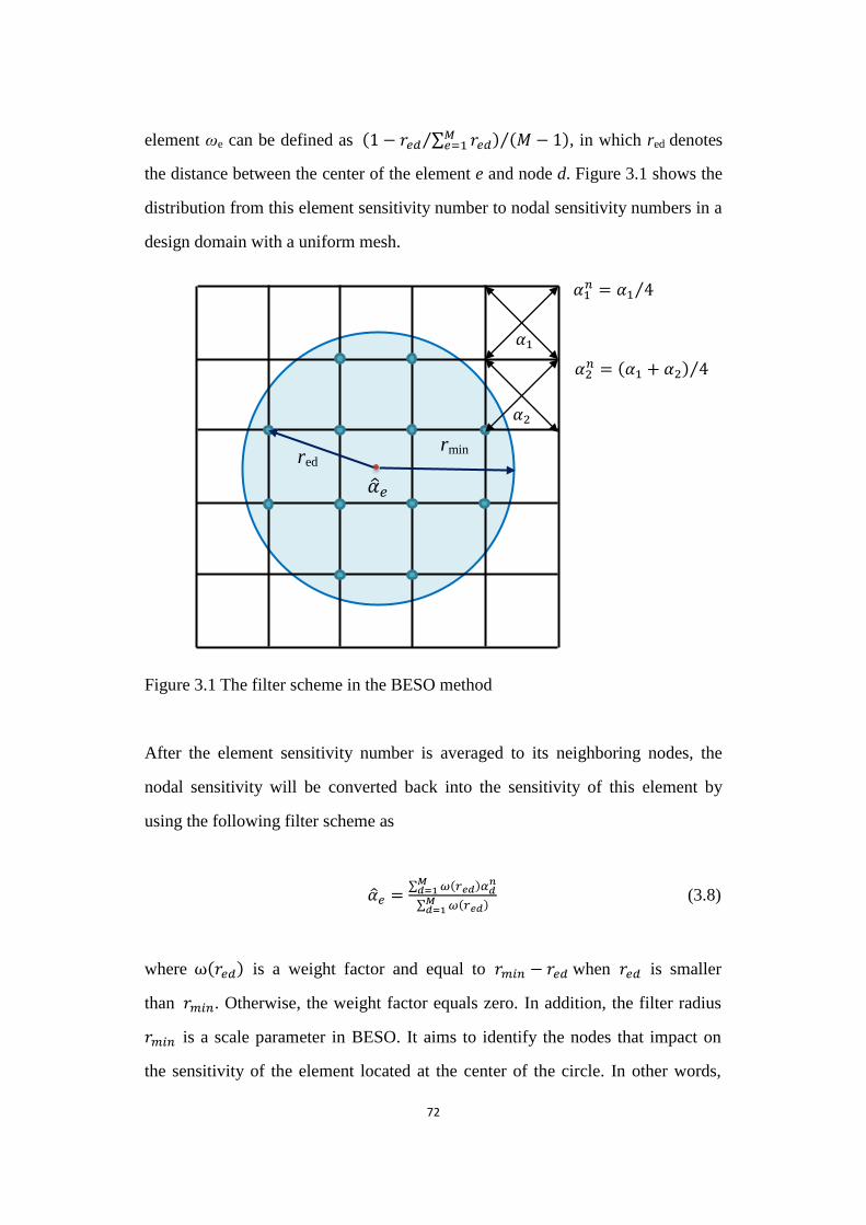
72
element ωe can be defined as (1 − 𝑟𝑒𝑑 ∑ 𝑟𝑒𝑑𝑀𝑒=1⁄ ) (𝑀 − 1)⁄ , in which red denotes
the distance between the center of the element e and node d. Figure 3.1 shows the
distribution from this element sensitivity number to nodal sensitivity numbers in a
design domain with a uniform mesh.
Figure 3.1 The filter scheme in the BESO method
Figure 3.1 The filter scheme in the BESO method
After the element sensitivity number is averaged to its neighboring nodes, the
nodal sensitivity will be converted back into the sensitivity of this element by
using the following filter scheme as
�̂�𝑒 =∑ 𝜔(𝑟𝑒𝑑)𝛼𝑑
𝑛𝑀𝑑=1
∑ 𝜔(𝑟𝑒𝑑)𝑀𝑑=1
(3.8)
where (𝑟𝑒𝑑) is a weight factor and equal to 𝑟𝑚𝑖𝑛 − 𝑟𝑒𝑑 when 𝑟𝑒𝑑 is smaller
than 𝑟𝑚𝑖𝑛. Otherwise, the weight factor equals zero. In addition, the filter radius
𝑟𝑚𝑖𝑛 is a scale parameter in BESO. It aims to identify the nodes that impact on
the sensitivity of the element located at the center of the circle. In other words,
𝛼1𝑛 = 𝛼1 4⁄
rmin red
𝛼2
𝛼1
𝛼2𝑛 = (𝛼1 + 𝛼2) 4⁄
�̂�𝑒
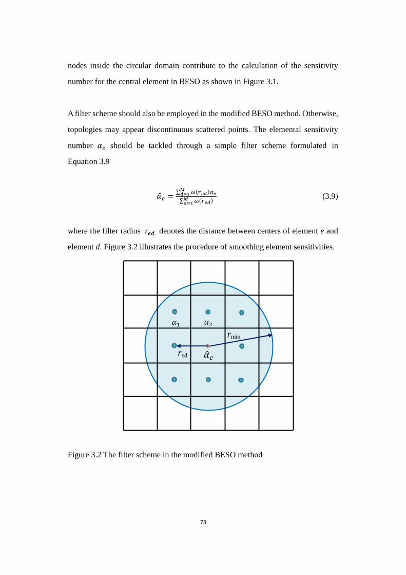
73
nodes inside the circular domain contribute to the calculation of the sensitivity
number for the central element in BESO as shown in Figure 3.1.
A filter scheme should also be employed in the modified BESO method. Otherwise,
topologies may appear discontinuous scattered points. The elemental sensitivity
number 𝛼𝑒 should be tackled through a simple filter scheme formulated in
Equation 3.9
�̂�𝑒 =∑ 𝜔(𝑟𝑒𝑑)𝛼𝑒𝑀𝑑=1
∑ 𝜔(𝑟𝑒𝑑)𝑀𝑑=1
(3.9)
where the filter radius 𝑟𝑒𝑑 denotes the distance between centers of element e and
element d. Figure 3.2 illustrates the procedure of smoothing element sensitivities.
Figure 3.2 The filter scheme in the modified BESO method
Figure 3.2 The filter scheme in the modified BESO method
rmin
red
𝛼2 𝛼1
�̂�𝑒
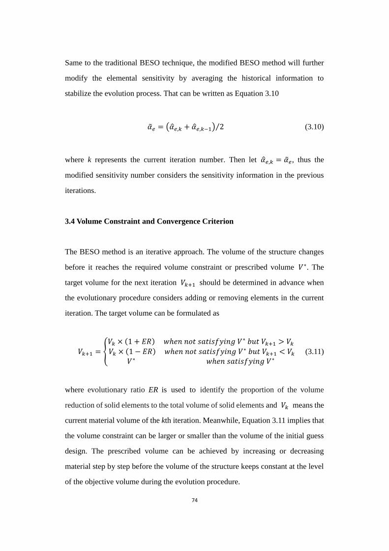
74
Same to the traditional BESO technique, the modified BESO method will further
modify the elemental sensitivity by averaging the historical information to
stabilize the evolution process. That can be written as Equation 3.10
�̃�𝑒 = (�̂�𝑒,𝑘 + �̂�𝑒,𝑘−1) 2⁄ (3.10)
where k represents the current iteration number. Then let �̂�𝑒,𝑘 = �̃�𝑒, thus the
modified sensitivity number considers the sensitivity information in the previous
iterations.
3.4 Volume Constraint and Convergence Criterion
The BESO method is an iterative approach. The volume of the structure changes
before it reaches the required volume constraint or prescribed volume 𝑉∗. The
target volume for the next iteration 𝑉𝑘+1 should be determined in advance when
the evolutionary procedure considers adding or removing elements in the current
iteration. The target volume can be formulated as
𝑉𝑘+1 = {
𝑉𝑘 × (1 + 𝐸𝑅) 𝑤𝑒𝑛 𝑛𝑜𝑡 𝑠𝑎𝑡𝑖𝑠𝑓𝑦𝑖𝑛𝑔 𝑉∗ 𝑏𝑢𝑡 𝑉𝑘+1 > 𝑉𝑘
𝑉𝑘 × (1 − 𝐸𝑅) 𝑤𝑒𝑛 𝑛𝑜𝑡 𝑠𝑎𝑡𝑖𝑠𝑓𝑦𝑖𝑛𝑔 𝑉∗ 𝑏𝑢𝑡 𝑉𝑘+1 < 𝑉𝑘
𝑉∗ 𝑤𝑒𝑛 𝑠𝑎𝑡𝑖𝑠𝑓𝑦𝑖𝑛𝑔 𝑉∗ (3.11)
where evolutionary ratio ER is used to identify the proportion of the volume
reduction of solid elements to the total volume of solid elements and 𝑉𝑘 means the
current material volume of the kth iteration. Meanwhile, Equation 3.11 implies that
the volume constraint can be larger or smaller than the volume of the initial guess
design. The prescribed volume can be achieved by increasing or decreasing
material step by step before the volume of the structure keeps constant at the level
of the objective volume during the evolution procedure.
75
To address material removal or addition, all elements including void (or soft) and
solid elements will be arranged in a descending order according to the values of
their sensitivity numbers. For solid elements, the elemental density is switched
from 1 to 0 (or 𝑚𝑖𝑛) if the criterion, 𝛼𝑒 ≤ 𝛼𝑡ℎ, is satisfied. As for void (or soft)
elements, the elemental density is changed from 0 (or 𝑚𝑖𝑛) to 1 if the criterion,
𝛼𝑒 > 𝛼𝑡ℎ, is satisfied. The reference variable 𝛼𝑡ℎ represents the threshold of the
sensitivity number which can be easily determined by the target material volume
and ranking of the sensitivity number. It is supposed that the optimization design is
a maximization problem. There are 1000 elements in the model. Sensitivity
numbers can be sorted as 𝛼1000 ≤ 𝛼 ≤ ⋯ ≤ 𝛼3 ≤ 𝛼2 ≤ 𝛼1 . 𝛼𝑡ℎ is equal to
𝛼 00 if 800 elements should remain in the model in order to achieve the target
volume Vk+1. (Huang and Xie, 2007).
In the modified BESO method, the evolutionary process can adopt the constant or
variable material volume pattern. For the former, the material volume can be kept
constant as 𝑉𝑘+1 = 𝑉∗ during the evolutionary process. Volume constraint can
be expressed as 𝑉∗ = ∑ 𝑉𝑒 𝑒,0𝑛𝑒=1 = ∑ 𝑉𝑒 𝑒 ( 𝑒 = 𝑒,1, 𝑒,2, … , 𝑜𝑟 𝑒,𝑚)
𝑛𝑒=1 . In
addition, the variable material volume pattern employed in the traditional BESO
method can also be applied to the modified BESO method. According to Equation
3.11, the target volume 𝑉𝑘+1 changes and 𝑉𝑘+1 𝑉∗ before it reaches the
required volume constraint or prescribed volume.
To achieve the volume constraint in the modified BESO method, the elements are
firstly sorted according to the values of their sensitivity number before
determining the appropriate threshold 𝛼𝑡ℎ . For example, it is assumed that
𝛼 1 ≤ 𝛼 0 ≤ ⋯ ≤ 𝛼3 ≤ 𝛼2 ≤ 𝛼1 in a design domain consisting of 9×9 elements.
The initial bound values of 𝛼𝑡ℎ are set as 𝛼𝑡ℎ,𝑙𝑜𝑤𝑒𝑟 = 𝛼 1 and 𝛼𝑡ℎ,𝑢𝑝𝑝𝑒𝑟 = 𝛼1.
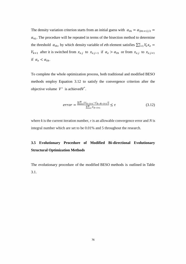
76
The density variation criterion starts from an initial guess with 𝛼𝑡ℎ = 𝛼( 1+1) 2⁄ =
𝛼41. The procedure will be repeated in terms of the bisection method to determine
the threshold 𝛼𝑡ℎ, by which density variable of eth element satisfies ∑ 𝑉𝑒 𝑒𝑛𝑒=1 =
𝑉𝑘+1 after it is switched from 𝑒,𝑗 to 𝑒,𝑗−1 if 𝛼𝑒 > 𝛼𝑡ℎ or from 𝑒,𝑗 to 𝑒,𝑗+1
if 𝛼𝑒 < 𝛼𝑡ℎ.
To complete the whole optimization process, both traditional and modified BESO
methods employ Equation 3.12 to satisfy the convergence criterion after the
objective volume 𝑉∗ is achievedV*.
𝑒𝑟𝑟𝑜𝑟 =|∑ (𝐶𝑘−𝑖+1−𝐶𝑘−𝑁−𝑖+1)𝑁𝑖=1 |
∑ 𝐶𝑘−𝑖+1𝑁𝑖=1
≤ 𝜏 (3.12)
where k is the current iteration number, τ is an allowable convergence error and N is
integral number which are set to be 0.01% and 5 throughout the research.
3.5 Evolutionary Procedure of Modified Bi-directional Evolutionary
Structural Optimization Methods
The evolutionary procedure of the modified BESO methods is outlined in Table
3.1.
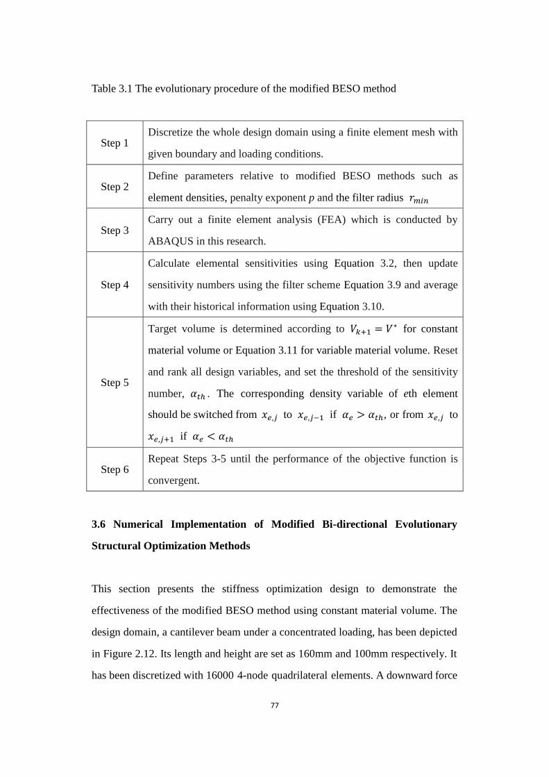
77
Table 3.1 The evolutionary procedure of the modified BESO method
Step 1 Discretize the whole design domain using a finite element mesh with
given boundary and loading conditions.
Step 2 Define parameters relative to modified BESO methods such as
element densities, penalty exponent p and the filter radius 𝑟𝑚𝑖𝑛
Step 3 Carry out a finite element analysis (FEA) which is conducted by
ABAQUS in this research.
Step 4
Calculate elemental sensitivities using Equation 3.2, then update
sensitivity numbers using the filter scheme Equation 3.9 and average
with their historical information using Equation 3.10.
Step 5
Target volume is determined according to 𝑉𝑘+1 = 𝑉∗ for constant
material volume or Equation 3.11 for variable material volume. Reset
and rank all design variables, and set the threshold of the sensitivity
number, 𝛼𝑡ℎ . The corresponding density variable of eth element
should be switched from 𝑒,𝑗 to 𝑒,𝑗−1 if 𝛼𝑒 > 𝛼𝑡ℎ, or from 𝑒,𝑗 to
𝑒,𝑗+1 if 𝛼𝑒 < 𝛼𝑡ℎ
Step 6 Repeat Steps 3-5 until the performance of the objective function is
convergent.
3.6 Numerical Implementation of Modified Bi-directional Evolutionary
Structural Optimization Methods
This section presents the stiffness optimization design to demonstrate the
effectiveness of the modified BESO method using constant material volume. The
design domain, a cantilever beam under a concentrated loading, has been depicted
in Figure 2.12. Its length and height are set as 160mm and 100mm respectively. It
has been discretized with 16000 4-node quadrilateral elements. A downward force
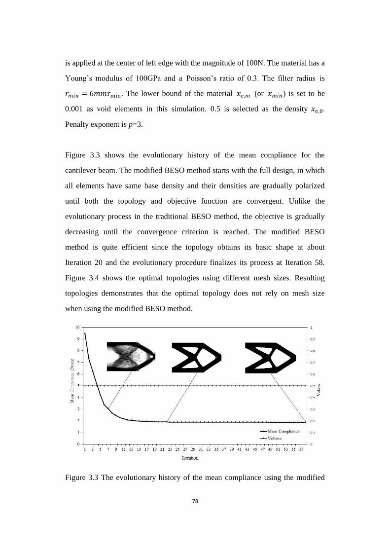
78
is applied at the center of left edge with the magnitude of 100N. The material has a
Young‟s modulus of 100GPa and a Poisson‟s ratio of 0.3. The filter radius is
𝑟𝑚𝑖𝑛 = 6 . The lower bound of the material 𝑒,𝑚 (or 𝑚𝑖𝑛) is set to be
0.001 as void elements in this simulation. 0.5 is selected as the density 𝑒,0.
Penalty exponent is p=3.
Figure 3.3 shows the evolutionary history of the mean compliance for the
cantilever beam. The modified BESO method starts with the full design, in which
all elements have same base density and their densities are gradually polarized
until both the topology and objective function are convergent. Unlike the
evolutionary process in the traditional BESO method, the objective is gradually
decreasing until the convergence criterion is reached. The modified BESO
method is quite efficient since the topology obtains its basic shape at about
Iteration 20 and the evolutionary procedure finalizes its process at Iteration 58.
Figure 3.4 shows the optimal topologies using different mesh sizes. Resulting
topologies demonstrates that the optimal topology does not rely on mesh size
when using the modified BESO method.
Figure 3.3 The evolutionary history of the mean compliance using the modified BESO method
Figure 3.3 The evolutionary history of the mean compliance using the modified
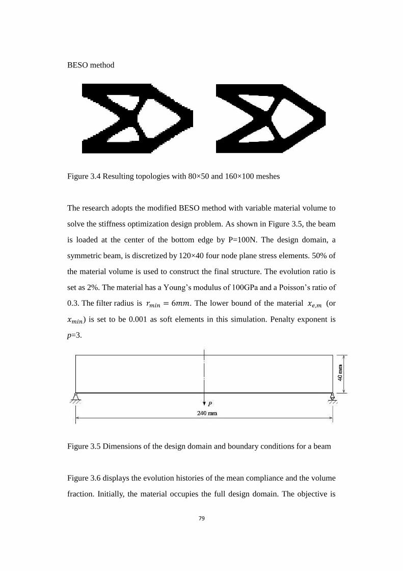
79
BESO method
Figure 3.4 Resulting topologies with 80×50 and 160×100 meshes
Figure 3.4 Resulting topologies with 80×50 and 160×100 meshes
The research adopts the modified BESO method with variable material volume to
solve the stiffness optimization design problem. As shown in Figure 3.5, the beam
is loaded at the center of the bottom edge by P=100N. The design domain, a
symmetric beam, is discretized by 120×40 four node plane stress elements. 50% of
the material volume is used to construct the final structure. The evolution ratio is
set as 2%. The material has a Young‟s modulus of 100GPa and a Poisson‟s ratio of
0.3. The filter radius is 𝑟𝑚𝑖𝑛 = 6 . The lower bound of the material 𝑒,𝑚 (or
𝑚𝑖𝑛) is set to be 0.001 as soft elements in this simulation. Penalty exponent is
p=3.
Figure 3.5 Dimensions of the design domain and boundary conditions for a beam
Figure 3.5 Dimensions of the design domain and boundary conditions for a beam
Figure 3.6 displays the evolution histories of the mean compliance and the volume
fraction. Initially, the material occupies the full design domain. The objective is
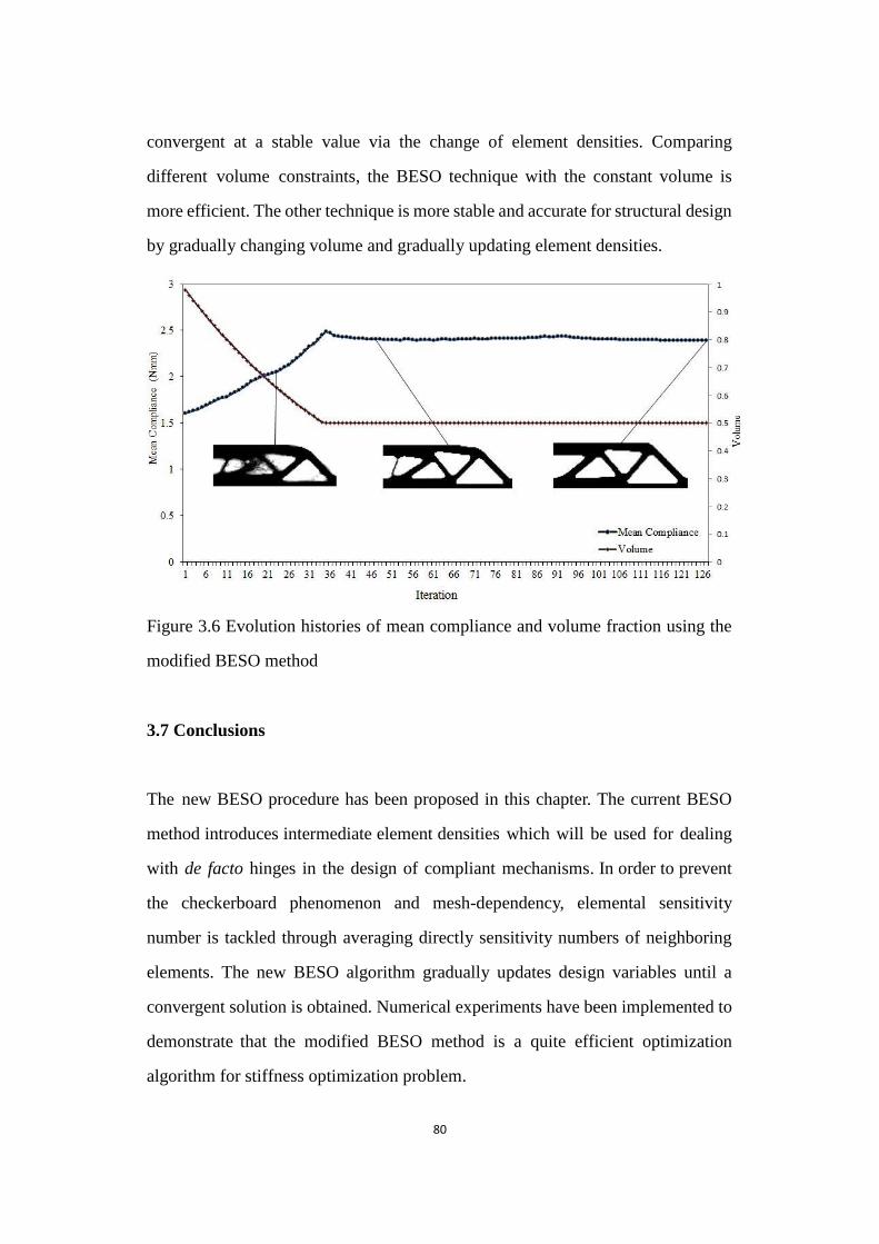
80
convergent at a stable value via the change of element densities. Comparing
different volume constraints, the BESO technique with the constant volume is
more efficient. The other technique is more stable and accurate for structural design
by gradually changing volume and gradually updating element densities.
Figure 3.6 Evolution histories of mean compliance and volume fraction using the modified BESO method
Figure 3.6 Evolution histories of mean compliance and volume fraction using the
modified BESO method
3.7 Conclusions
The new BESO procedure has been proposed in this chapter. The current BESO
method introduces intermediate element densities which will be used for dealing
with de facto hinges in the design of compliant mechanisms. In order to prevent
the checkerboard phenomenon and mesh-dependency, elemental sensitivity
number is tackled through averaging directly sensitivity numbers of neighboring
elements. The new BESO algorithm gradually updates design variables until a
convergent solution is obtained. Numerical experiments have been implemented to
demonstrate that the modified BESO method is a quite efficient optimization
algorithm for stiffness optimization problem.
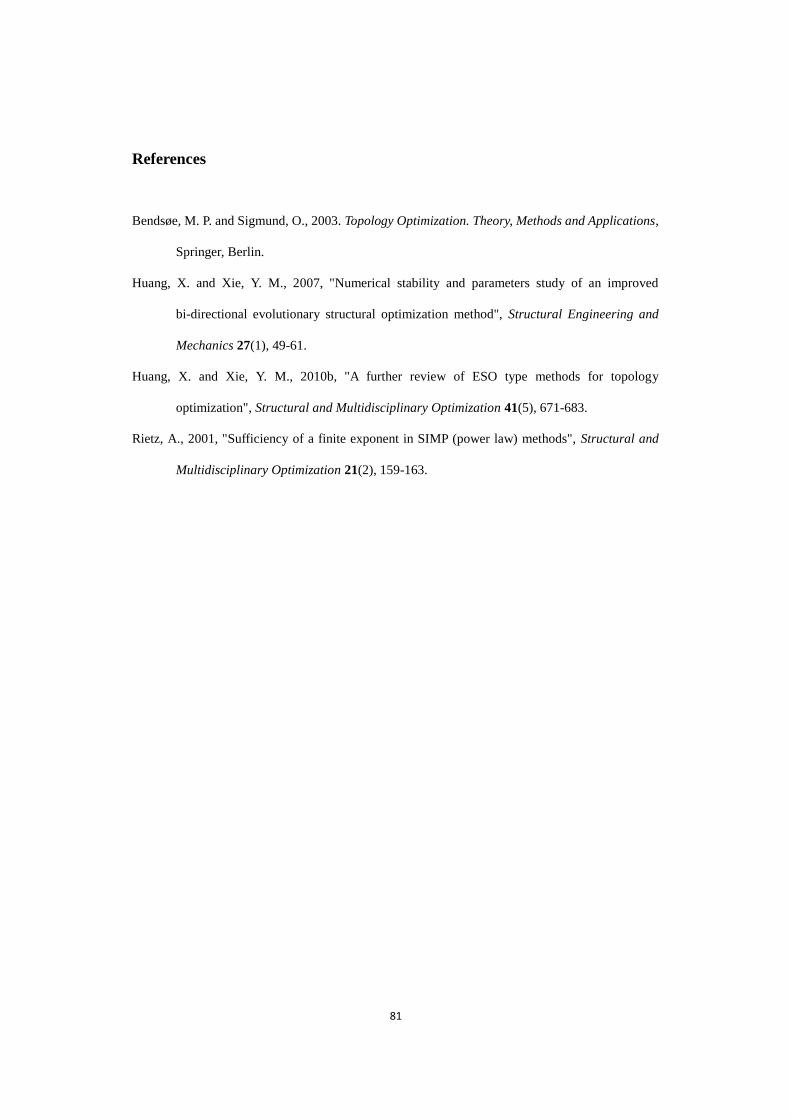
81
References
Bendsøe, M. P. and Sigmund, O., 2003. Topology Optimization. Theory, Methods and Applications,
Springer, Berlin.
Huang, X. and Xie, Y. M., 2007, "Numerical stability and parameters study of an improved
bi-directional evolutionary structural optimization method", Structural Engineering and
Mechanics 27(1), 49-61.
Huang, X. and Xie, Y. M., 2010b, "A further review of ESO type methods for topology
optimization", Structural and Multidisciplinary Optimization 41(5), 671-683.
Rietz, A., 2001, "Sufficiency of a finite exponent in SIMP (power law) methods", Structural and
Multidisciplinary Optimization 21(2), 159-163.

82
Chapter 4
Effects of Spring Stiffness on Topology
Design of Linear Compliant
Mechanisms
83
Chapter Overview
The dissertation has reviewed previous work related to the optimal design of
compliant mechanisms. The dissertation has also demonstrated that the traditional
BESO method and modified BESO methods are capable of generating reliable and
practical topologies with high computational efficiency for stiffness optimization
problems.
In this chapter, the research presents topology optimization approaches for the
optimal design of linear compliant mechanisms. The optimization approach uses
several objective functions and employs the modified BESO method with constant
material volume. The sensitivity analysis is performed by applying the adjoint
method. The evolutionary procedure gradually switches elements‟ densities until
optimal topologies are achieved. This chapter then analyzes the stored energy
after deformation, output displacement and spring effect when using different
objective function.
4.1 Optimization Problem and Structural Analysis
Using structural topology optimization in the optimal design of monolithic
compliant mechanisms is an innovative method (Ananthasuresh, 2003). Within
the topology optimization framework, a variety of objective functions have been
defined to find a compliant mechanism with the desired performance (Sigmund,
1997; Saxena and Ananthasuresh, 2001; Ansola et al., 2007; Luo et al., 2007; Lin
et al., 2010). For designing compliant mechanisms, it is quite necessary to
consider and quantify the performance characteristics of compliant mechanisms,
which have been reviewed in Section 2.2.1, such as the output displacement,
mechanical advantage (MA), geometric advantage (GA) and mechanical
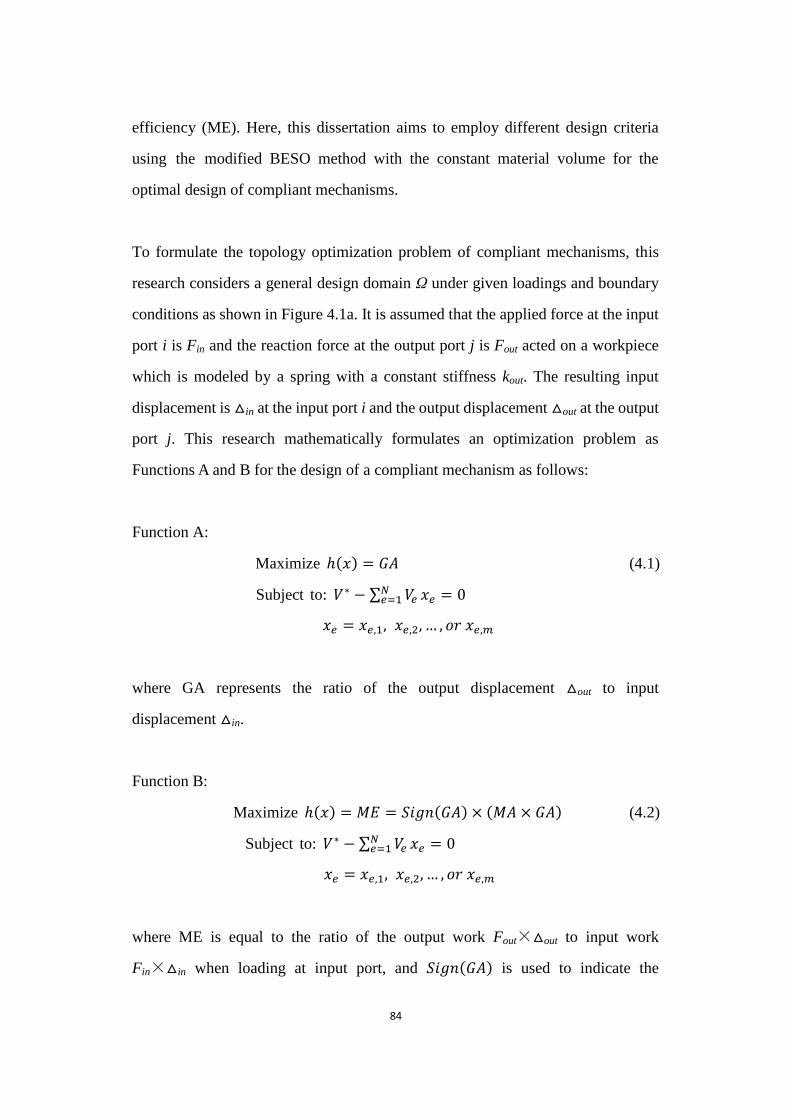
84
efficiency (ME). Here, this dissertation aims to employ different design criteria
using the modified BESO method with the constant material volume for the
optimal design of compliant mechanisms.
To formulate the topology optimization problem of compliant mechanisms, this
research considers a general design domain Ω under given loadings and boundary
conditions as shown in Figure 4.1a. It is assumed that the applied force at the input
port i is Fin and the reaction force at the output port j is Fout acted on a workpiece
which is modeled by a spring with a constant stiffness kout. The resulting input
displacement is △in at the input port i and the output displacement △out at the output
port j. This research mathematically formulates an optimization problem as
Functions A and B for the design of a compliant mechanism as follows:
Function A:
Maximize ( ) = 𝐺𝐴 (4.1)
Subject to: 𝑉∗ − ∑ 𝑉𝑒𝑁𝑒=1 𝑒 = 0
𝑒 = 𝑒,1, 𝑒,2, … , 𝑜𝑟 𝑒,𝑚
where GA represents the ratio of the output displacement △out to input
displacement △in.
Function B:
Maximize ( ) = 𝑀𝐸 = 𝑆𝑖𝑔𝑛(𝐺𝐴) × (𝑀𝐴 × 𝐺𝐴) (4.2)
Subject to: 𝑉∗ − ∑ 𝑉𝑒𝑁𝑒=1 𝑒 = 0
𝑒 = 𝑒,1, 𝑒,2, … , 𝑜𝑟 𝑒,𝑚
where ME is equal to the ratio of the output work Fout×△out to input work
Fin×△in when loading at input port, and 𝑆𝑖𝑔𝑛(𝐺𝐴) is used to indicate the
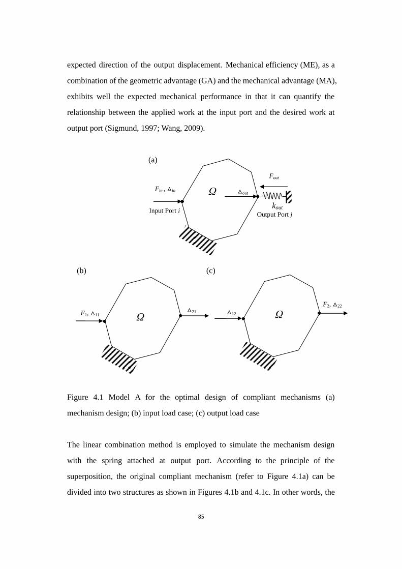
85
expected direction of the output displacement. Mechanical efficiency (ME), as a
combination of the geometric advantage (GA) and the mechanical advantage (MA),
exhibits well the expected mechanical performance in that it can quantify the
relationship between the applied work at the input port and the desired work at
output port (Sigmund, 1997; Wang, 2009).
(a)
(b) (c)
Figure 4.1 Model A for the optimal design of compliant mechanisms
Figure 4.1 Model A for the optimal design of compliant mechanisms (a)
mechanism design; (b) input load case; (c) output load case
The linear combination method is employed to simulate the mechanism design
with the spring attached at output port. According to the principle of the
superposition, the original compliant mechanism (refer to Figure 4.1a) can be
divided into two structures as shown in Figures 4.1b and 4.1c. In other words, the
Input Port i
Fin , △in
Output Port j
kout
Fout
Ω △out
F1, △11 △21
Ω
△12
F2, △22
Ω

86
compliant mechanism is equivalent to the linear combination of two structures
when the following displacement relationships are satisfied:
∆𝑖𝑛= ∆11 + 𝑐 × ∆12 (4.3)
∆𝑜𝑢𝑡= ∆21 + 𝑐 × ∆22
where △ij denotes the displacement at the port i due to the applied force Fj. c is the
combination coefficient to be determined. Meanwhile, the forces should satisfy the
following relationships
𝐹𝑖𝑛 = 𝐹1 (4.4)
𝐹𝑜𝑢𝑡 = −𝑐 × 𝐹2 = 𝑘𝑜𝑢𝑡 × ∆𝑜𝑢𝑡
Thus, the combination coefficient c can be identified as
𝑐 = −∆21𝑘𝑜
2+∆22𝑘𝑜 (4.5)
Substituting Equation 4.5 into Equations 4.3 and 4.4, the input and output
displacements can be can be expressed as
∆𝑖𝑛= ∆11 −𝑘𝑜 ∆21∆12
2+∆22𝑘𝑜 (4.6)
∆𝑜𝑢𝑡= 2∆21
2+∆22𝑘𝑜
Thus Function A using the geometric advantage can be stated as Equation 4.7
𝐺𝐴 = ∆𝑜𝑢𝑡 ∆𝑖𝑛⁄ = (𝐹2∆21) (𝐹2∆11 + ∆11∆22𝑘𝑜𝑢𝑡 − ∆21∆12𝑘𝑜𝑢𝑡)⁄ (4.7)
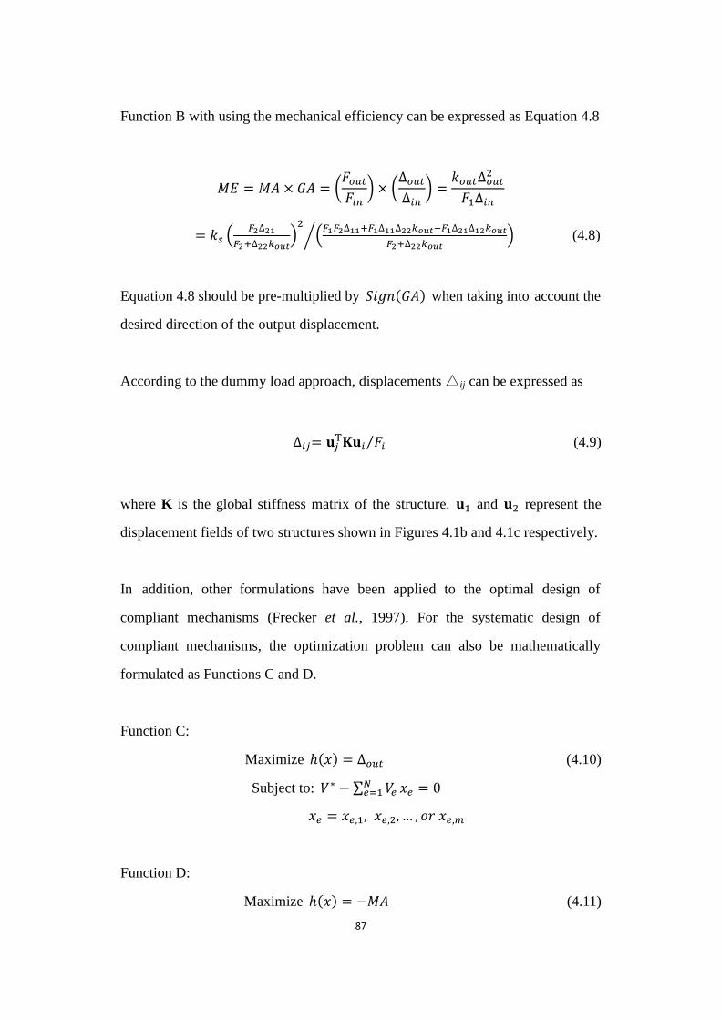
87
Function B with using the mechanical efficiency can be expressed as Equation 4.8
𝑀𝐸 = 𝑀𝐴 × 𝐺𝐴 = (𝐹𝑜𝑢𝑡𝐹𝑖𝑛
) × (∆𝑜𝑢𝑡∆𝑖𝑛
) =𝑘𝑜𝑢𝑡∆𝑜𝑢𝑡
2
𝐹1∆𝑖𝑛
= 𝑘 ( 2∆21
2+∆22𝑘𝑜 )2
( 1 2∆11+ 1∆11∆22𝑘𝑜 − 1∆21∆12𝑘𝑜
2+∆22𝑘𝑜 )⁄ (4.8)
Equation 4.8 should be pre-multiplied by 𝑆𝑖𝑔𝑛(𝐺𝐴) when taking into account the
desired direction of the output displacement.
According to the dummy load approach, displacements △ij can be expressed as
∆𝑖𝑗= 𝐮𝑗 𝐮𝑖 𝐹𝑖⁄ (4.9)
where K is the global stiffness matrix of the structure. 𝐮1 and 𝐮2 represent the
displacement fields of two structures shown in Figures 4.1b and 4.1c respectively.
In addition, other formulations have been applied to the optimal design of
compliant mechanisms (Frecker et al., 1997). For the systematic design of
compliant mechanisms, the optimization problem can also be mathematically
formulated as Functions C and D.
Function C:
Maximize ( ) = ∆𝑜𝑢𝑡 (4.10)
Subject to: 𝑉∗ − ∑ 𝑉𝑒𝑁𝑒=1 𝑒 = 0
𝑒 = 𝑒,1, 𝑒,2, … , 𝑜𝑟 𝑒,𝑚
Function D:
Maximize ( ) = −𝑀𝐴 (4.11)
88
Subject to: 𝑉∗ − ∑ 𝑉𝑒𝑁𝑒=1 𝑒 = 0
𝑒 = 𝑒,1, 𝑒,2, … , 𝑜𝑟 𝑒,𝑚
where MA represents the ratio of the output force Fout to input force Fin.
The topology may suffer a material disconnection between input and output ports
when simply using Function C (Wang, 2009). For Model A in which an external
spring is attached to the output port, the determinant of the mechanism stiffness
matrix, det (Km), cannot be equal to zero so that the matrix is no longer singular. To
avoid the presence of structural discontinuity, this research considers either
employing a corresponding input constraint or attaching an external spring at input
port for maximizing the magnitude ∆𝑜𝑢𝑡. Appendix A presents its elastic analysis.
Model B is proposed for the optimal design of compliant mechanisms by attaching
a spring at input port with a constant stiffness kin when using Function C, shown in
Figure 4.2. In addition, Function D can be written as = 𝐹𝑜𝑢𝑡 𝐹𝑖𝑛⁄ =
𝑘𝑜𝑢𝑡∆𝑜𝑢𝑡 𝐹𝑖𝑛⁄ , the sensitivity rank of which is the same as that of Function C due to
constant variables kout and Fin. Therefore, this research takes advantage of Model B
to optimize the compliant mechanism design using Function C or D.
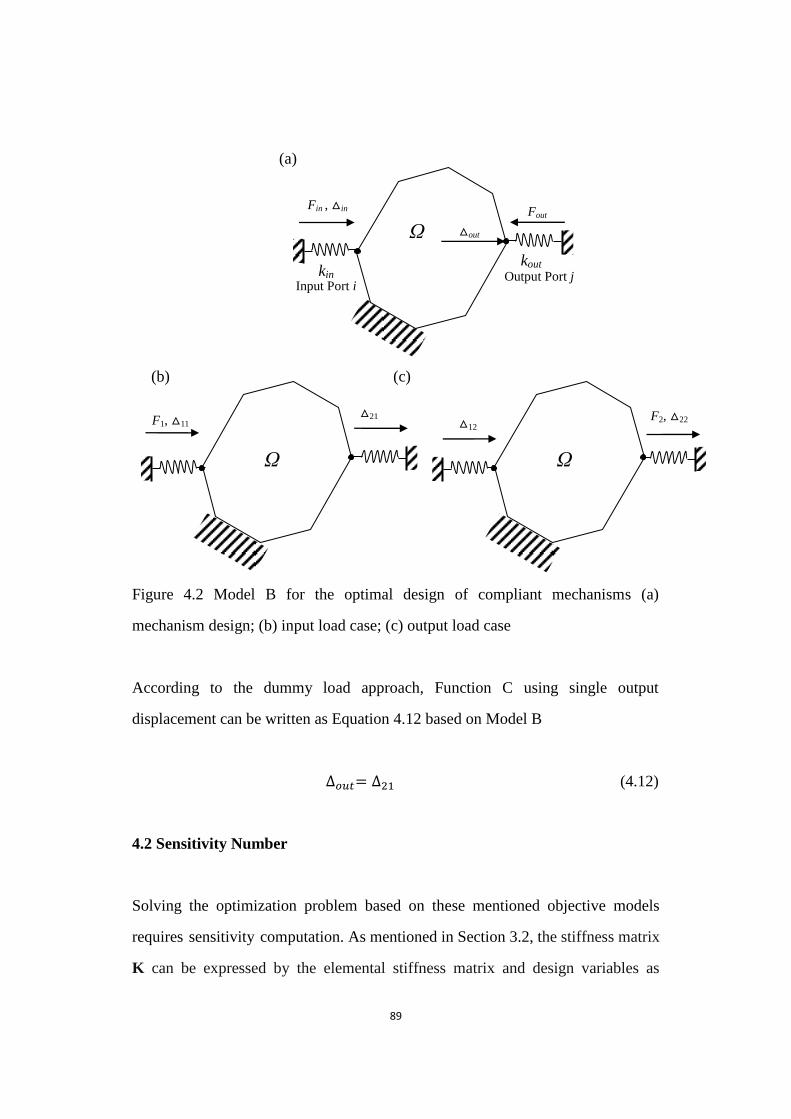
89
(a)
(b) (c)
Figure 4.2 Model B for the optimal design of compliant mechanisms
Figure 4.2 Model B for the optimal design of compliant mechanisms (a)
mechanism design; (b) input load case; (c) output load case
According to the dummy load approach, Function C using single output
displacement can be written as Equation 4.12 based on Model B
∆𝑜𝑢𝑡= ∆21 (4.12)
4.2 Sensitivity Number
Solving the optimization problem based on these mentioned objective models
requires sensitivity computation. As mentioned in Section 3.2, the stiffness matrix
K can be expressed by the elemental stiffness matrix and design variables as
Input Port i
Fin , △in
Output Port j kin
Fout
Ω △out
kout
F1, △11 △21
Ω
△12 F2, △22
Ω
90
= ∑ 𝑒𝑝 𝑒
0𝑒 when the binary design variable 𝑒 can switch between 𝑚𝑖𝑛 and 1.
The global stiffness matrix can be written as = ∑ ( 𝑒,𝑗 𝑒,0⁄ )𝑝 𝑒0
𝑒 when
intermediate densities are introduced in the modified BESO method.
The sensitivity of displacement variables shown in Equation 4.9 can be obtained
by differentiating expression given in Equation 4.13
∆𝑖
𝑥𝑒= (
𝜕𝐮
𝜕𝑥𝑒 𝐮𝑖 + 𝐮𝑗
𝜕
𝜕𝑥𝑒𝐮𝑖 + 𝐮𝑗
𝜕𝐮𝑖
𝜕𝑥𝑒) 𝐹𝑖⁄ (4.13)
The following equations can be found since external forces are
design-independent in equilibrium equations 𝐮𝑖 = 𝑖 and 𝐮𝑗 = 𝑗.
𝜕
𝜕𝑥𝑒𝐮𝑖 +
𝜕𝐮𝑖
𝜕𝑥𝑒= 0 (4.14)
𝜕
𝜕𝑥𝑒𝐮𝑗 +
𝜕𝐮
𝜕𝑥𝑒= 0
Substituting Equation 4.13 into Equation 4.14, the sensitivity of displacements
ij can be found as
∆𝑖
𝑥𝑒= −(𝐮𝑗
𝜕
𝜕𝑥𝑒𝐮𝑖) 𝐹𝑖⁄ (4.15)
The sensitivity of the displacement can be expressed at elemental levels for solid
and soft elements as discrete design variables are employed in the modified BESO
method.
∆𝑖
𝑥𝑒= −𝑝 𝑒
𝑝−1𝐮𝑗,𝑒 𝑒
0𝐮𝑖,𝑒 ( 0𝑝𝐹𝑖)⁄ 𝑤𝑒𝑛 𝑒 = 𝑒,1, 𝑒,2, … , 𝑒,𝑚−1 𝑜𝑟 𝑒,𝑚
(4.16)
91
With the help of Equation 4.12, the sensitivity of Function C can be obtained
according to Model B
𝛼𝑒 = ∆𝑜
𝑥𝑒= ∆21
𝑥𝑒 (4.17)
For the sensitivity numbers of Functions A and B, the linear combination method is
employed to simulate the mechanism design by coupling two load cases depicted
in Model A. According to Equation 4.5, the derivatives of the combination
coefficient c can be defined as
𝑐
𝑥𝑒= −
𝑘𝑜 ( 2+∆22𝑘𝑜 ) ∆21 𝑒
−𝑘𝑜 2 ∆21
∆22 𝑒
( 2+∆22𝑘𝑜 )2 (4.18)
and the derivatives of the input and output displacements according to Equation 4.3
are
∆𝑜
𝑥𝑒=𝜕∆21
𝜕𝑥𝑒+
𝜕𝑐
𝜕𝑥𝑒∆22 + 𝑐
𝜕∆22
𝜕𝑥𝑒 (4.19)
∆𝑖𝑛
𝑥𝑒=𝜕∆11
𝜕𝑥𝑒+
𝜕𝑐
𝜕𝑥𝑒∆12 + 𝑐
𝜕∆12
𝜕𝑥𝑒
Thus, the sensitivity of the geometric advantage of Function A can be obtained.
𝛼𝑒 =
𝑥𝑒= (∆𝑖𝑛 ×
𝜕∆𝑜
𝜕𝑥𝑒− ∆𝑜𝑢𝑡 ×
𝜕∆𝑖𝑛
𝜕𝑥𝑒) ∆𝑖𝑛
2⁄ (4.20)
With the help of Equation 4.8, the sensitivity of the mechanical efficiency of
Function B can be obtained
92
𝛼𝑒 = 𝑆𝑖𝑔𝑛(𝐺𝐴) × 𝑀
𝑥𝑒= 𝑆𝑖𝑔𝑛(𝐺𝐴) × 𝑘𝑜𝑢𝑡 (2∆𝑖𝑛∆𝑜𝑢𝑡
∆𝑜
𝑥𝑒− ∆𝑜𝑢𝑡
2 ∆𝑖𝑛
𝑥𝑒) (𝐹1∆𝑖𝑛
2 )⁄
(4.21)
4.3 Numerical Implementation
Here, the post-processing techniques of the modified BESO method are employed
in the optimal design of linear compliant mechanisms. To avoid checkerboard and
mesh-dependency, a filter scheme is used by Equation 3.9. The elemental
sensitivity number is tackled by averaging sensitivity numbers from neighboring
elements. Secondly, Equation 3.10 is adopted for the stabilization of the
evolutionary process. Finally, the modified BESO will complete the whole
optimization process of design compliant mechanisms once the performance of
the objective function satisfies the convergence criterion (refer to Equation 3.12).
4.4 Iterative Procedure
The procedure of optimizing compliant mechanisms with using the modified
BESO method is listed in the following steps, summarizing the previous sections
in this chapter. In addition, Figure 4.3 describes visually and briefly its iterative
procedure.
Step 1 Present the design domain with boundary conditions for optimizing
compliant mechanism. Discretize the whole design domain using a finite element
mesh. Set material properties such as Young‟s modulus and Poisson‟s ratio.
Define BESO parameters like penalty exponent p, the filter radius 𝑟𝑚𝑖𝑛 , the
allowable convergence error τ and intermediate densities
Step 2 Carry out a finite element analysis which is conducted by ABAQUS. Output
93
required data, such as displacements.
Step 3 The sensitivity number is calculated according to Equation 4.20 for
Function A, Equation 4.21 for Function B and Equation 4.17 for Function C.
Step 4 Update sensitivity numbers by the filter scheme Equation 3.9 and average
with their historical information by Equation 3.10.
Step 5 Reset and rank all design variables, and set the threshold of the sensitivity
number, 𝛼𝑡ℎ , which is determined according to the target material volume
constraint 𝑉∗ = ∑ 𝑉𝑒 𝑒,0 =𝑛𝑒=1 ∑ 𝑉𝑒 𝑒 ( 𝑒 = 𝑒,1, 𝑒,2, … , 𝑜𝑟 𝑒,𝑚)
𝑛𝑒=1 . The
corresponding density variable of eth element should be switched from 𝑒,𝑗 to
𝑒,𝑗−1 if 𝛼𝑒 > 𝛼𝑡ℎ, or from 𝑒,𝑗 to 𝑒,𝑗+1 if 𝛼𝑒 < 𝛼𝑡ℎ.
Step 6 Repeat Steps 2-5 until the volume fraction reaches target volume and the
performance of objective function satisfies its convergence criteria according to
Equation 3.12.
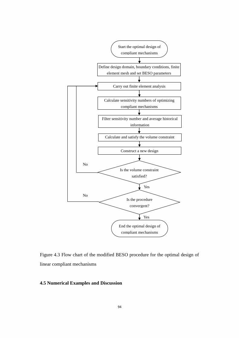
94
Figure 4.3 Flow chart of the modified BESO procedure for the optimal design of linear compliant mechanisms
Figure 4.3 Flow chart of the modified BESO procedure for the optimal design of
linear compliant mechanisms
4.5 Numerical Examples and Discussion
No
Yes
Yes
End the optimal design of
compliant mechanisms
Start the optimal design of
compliant mechanisms
Define design domain, boundary conditions, finite
element mesh and set BESO parameters
Carry out finite element analysis
Calculate sensitivity numbers of optimizing
compliant mechanisms
Filter sensitivity number and average historical
information
Calculate and satisfy the volume constraint
Construct a new design
Is the volume constraint
satisfied?
Is the procedure
convergent?
No
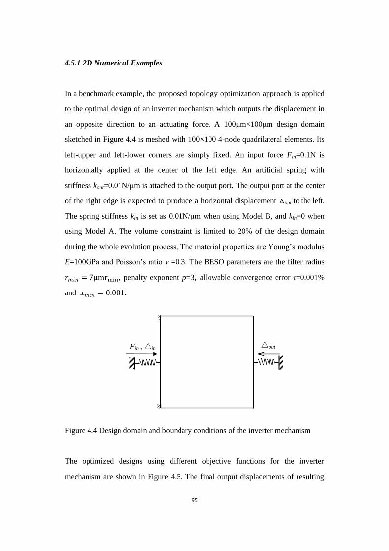
95
4.5.1 2D Numerical Examples
In a benchmark example, the proposed topology optimization approach is applied
to the optimal design of an inverter mechanism which outputs the displacement in
an opposite direction to an actuating force. A 100μm×100μm design domain
sketched in Figure 4.4 is meshed with 100×100 4-node quadrilateral elements. Its
left-upper and left-lower corners are simply fixed. An input force Fin=0.1N is
horizontally applied at the center of the left edge. An artificial spring with
stiffness kout=0.01N/μm is attached to the output port. The output port at the center
of the right edge is expected to produce a horizontal displacement △out to the left.
The spring stiffness kin is set as 0.01N/μm when using Model B, and kin=0 when
using Model A. The volume constraint is limited to 20% of the design domain
during the whole evolution process. The material properties are Young‟s modulus
E=100GPa and Poisson‟s ratio ν =0.3. The BESO parameters are the filter radius
𝑟𝑚𝑖𝑛 = 7 , penalty exponent p=3, allowable convergence error τ=0.001%
and 𝑚𝑖𝑛 = 0 001.
Figure 4.4 Design domain and boundary conditions of the inverter mechanism
Figure 4.4 Design domain and boundary conditions of the inverter mechanism
The optimized designs using different objective functions for the inverter
mechanism are shown in Figure 4.5. The final output displacements of resulting
△out Fin , △in
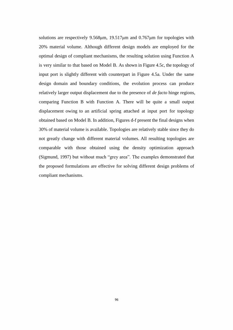
96
solutions are respectively 9.568μm, 19.517μm and 0.767μm for topologies with
20% material volume. Although different design models are employed for the
optimal design of compliant mechanisms, the resulting solution using Function A
is very similar to that based on Model B. As shown in Figure 4.5c, the topology of
input port is slightly different with counterpart in Figure 4.5a. Under the same
design domain and boundary conditions, the evolution process can produce
relatively larger output displacement due to the presence of de facto hinge regions,
comparing Function B with Function A. There will be quite a small output
displacement owing to an artificial spring attached at input port for topology
obtained based on Model B. In addition, Figures d-f present the final designs when
30% of material volume is available. Topologies are relatively stable since they do
not greatly change with different material volumes. All resulting topologies are
comparable with those obtained using the density optimization approach
(Sigmund, 1997) but without much “grey area”. The examples demonstrated that
the proposed formulations are effective for solving different design problems of
compliant mechanisms.
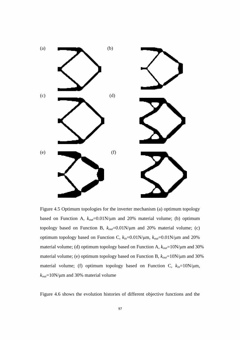
97
(a) (b)
(c) (d)
(e) (f)
Figure 4.5 Optimum topologies for the inverter mechanism
Figure 4.5 Optimum topologies for the inverter mechanism (a) optimum topology
based on Function A, kout=0.01N/μm and 20% material volume; (b) optimum
topology based on Function B, kout=0.01N/μm and 20% material volume; (c)
optimum topology based on Function C, kin=0.01N/μm, kout=0.01N/μm and 20%
material volume; (d) optimum topology based on Function A, kout=10N/μm and 30%
material volume; (e) optimum topology based on Function B, kout=10N/μm and 30%
material volume; (f) optimum topology based on Function C, kin=10N/μm,
kout=10N/μm and 30% material volume
Figure 4.6 shows the evolution histories of different objective functions and the
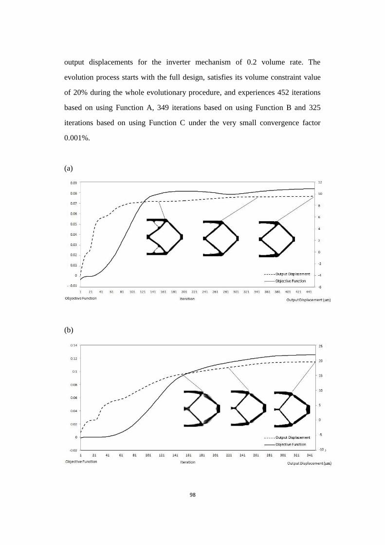
98
output displacements for the inverter mechanism of 0.2 volume rate. The
evolution process starts with the full design, satisfies its volume constraint value
of 20% during the whole evolutionary procedure, and experiences 452 iterations
based on using Function A, 349 iterations based on using Function B and 325
iterations based on using Function C under the very small convergence factor
0.001%.
(a)
(b)
99
(c)
Figure 4.6 Evolution histories of the inverter mechanism using different design problems
Figure 4.6 Evolution histories of the inverter mechanism using different design
problems: (a) evolution history based on Function A; (b) evolution history based on
Function B; (c) evolution history based on Function C
Figure 4.7 proposes the trend lines for plotting the relationship between the spring
stiffness of output port and values of objective functions of final design,
demonstrating the effects on objective functions from the output spring stiffness.
The optimization process also presents the resulting solutions when using different
spring stiffness for Functions A and B with the filter radius 𝑟𝑚𝑖𝑛 = 3 and 20%
material volume constraint.
Obviously, it can be seen that the geometrical advantage and mechanical
efficiency are decreasing with the spring stiffness becomes greater. In addition,
the resulting solution also tends to be a simpler topology. The difference is that
the former tends to be an exponential decrease, but the mechanical efficiency
shows a linear decrease. The smaller the output spring stiffness, the more de facto
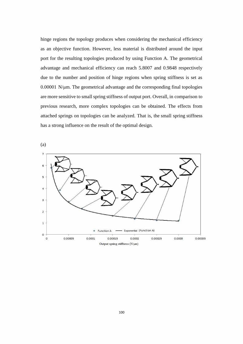
100
hinge regions the topology produces when considering the mechanical efficiency
as an objective function. However, less material is distributed around the input
port for the resulting topologies produced by using Function A. The geometrical
advantage and mechanical efficiency can reach 5.8007 and 0.9848 respectively
due to the number and position of hinge regions when spring stiffness is set as
0.00001 N/μm. The geometrical advantage and the corresponding final topologies
are more sensitive to small spring stiffness of output port. Overall, in comparison to
previous research, more complex topologies can be obtained. The effects from
attached springs on topologies can be analyzed. That is, the small spring stiffness
has a strong influence on the result of the optimal design.
(a)
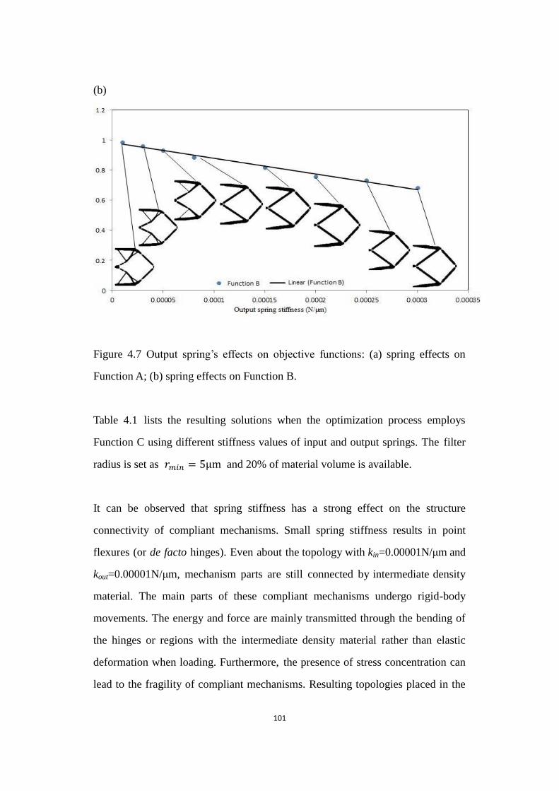
101
(b)
Figure 4.7 Output spring‟s effects on objective functions
Figure 4.7 Output spring‟s effects on objective functions: (a) spring effects on
Function A; (b) spring effects on Function B.
Table 4.1 lists the resulting solutions when the optimization process employs
Function C using different stiffness values of input and output springs. The filter
radius is set as 𝑟𝑚𝑖𝑛 = 5 and 20% of material volume is available.
It can be observed that spring stiffness has a strong effect on the structure
connectivity of compliant mechanisms. Small spring stiffness results in point
flexures (or de facto hinges). Even about the topology with kin=0.00001N/μm and
kout=0.00001N/μm, mechanism parts are still connected by intermediate density
material. The main parts of these compliant mechanisms undergo rigid-body
movements. The energy and force are mainly transmitted through the bending of
the hinges or regions with the intermediate density material rather than elastic
deformation when loading. Furthermore, the presence of stress concentration can
lead to the fragility of compliant mechanisms. Resulting topologies placed in the
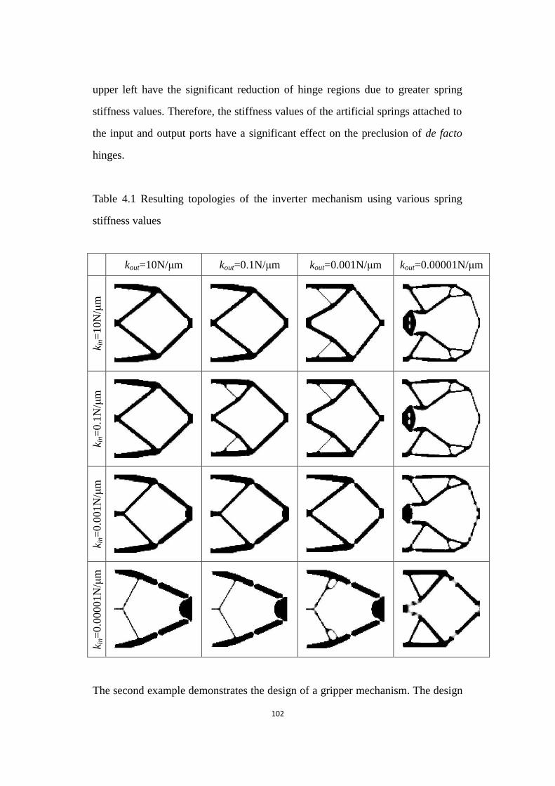
102
upper left have the significant reduction of hinge regions due to greater spring
stiffness values. Therefore, the stiffness values of the artificial springs attached to
the input and output ports have a significant effect on the preclusion of de facto
hinges.
Table 4.1 Resulting topologies of the inverter mechanism using various spring
stiffness values
kout=10N/μm kout=0.1N/μm kout=0.001N/μm kout=0.00001N/μm
k in=
10N
/μm
k in=
0.1
N/μ
m
k in=
0.0
01N
/μm
k in=
0.0
0001N
/μm
The second example demonstrates the design of a gripper mechanism. The design
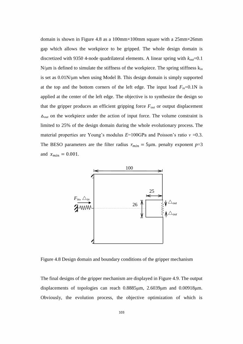
103
domain is shown in Figure 4.8 as a 100mm×100mm square with a 25mm×26mm
gap which allows the workpiece to be gripped. The whole design domain is
discretized with 9350 4-node quadrilateral elements. A linear spring with kout=0.1
N/μm is defined to simulate the stiffness of the workpiece. The spring stiffness kin
is set as 0.01N/μm when using Model B. This design domain is simply supported
at the top and the bottom corners of the left edge. The input load Fin=0.1N is
applied at the center of the left edge. The objective is to synthesize the design so
that the gripper produces an efficient gripping force Fout or output displacement
△out on the workpiece under the action of input force. The volume constraint is
limited to 25% of the design domain during the whole evolutionary process. The
material properties are Young‟s modulus E=100GPa and Poisson‟s ratio ν =0.3.
The BESO parameters are the filter radius 𝑟𝑚𝑖𝑛 = 5 . penalty exponent p=3
and 𝑚𝑖𝑛 = 0 001.
Figure 4.8 Design domain and boundary conditions of the gripper mechanism
Figure 4.8 Design domain and boundary conditions of the gripper mechanism
The final designs of the gripper mechanism are displayed in Figure 4.9. The output
displacements of topologies can reach 0.8885μm, 2.6039μm and 0.00918μm.
Obviously, the evolution process, the objective optimization of which is
100
Fin, △in △out
△out
26
25
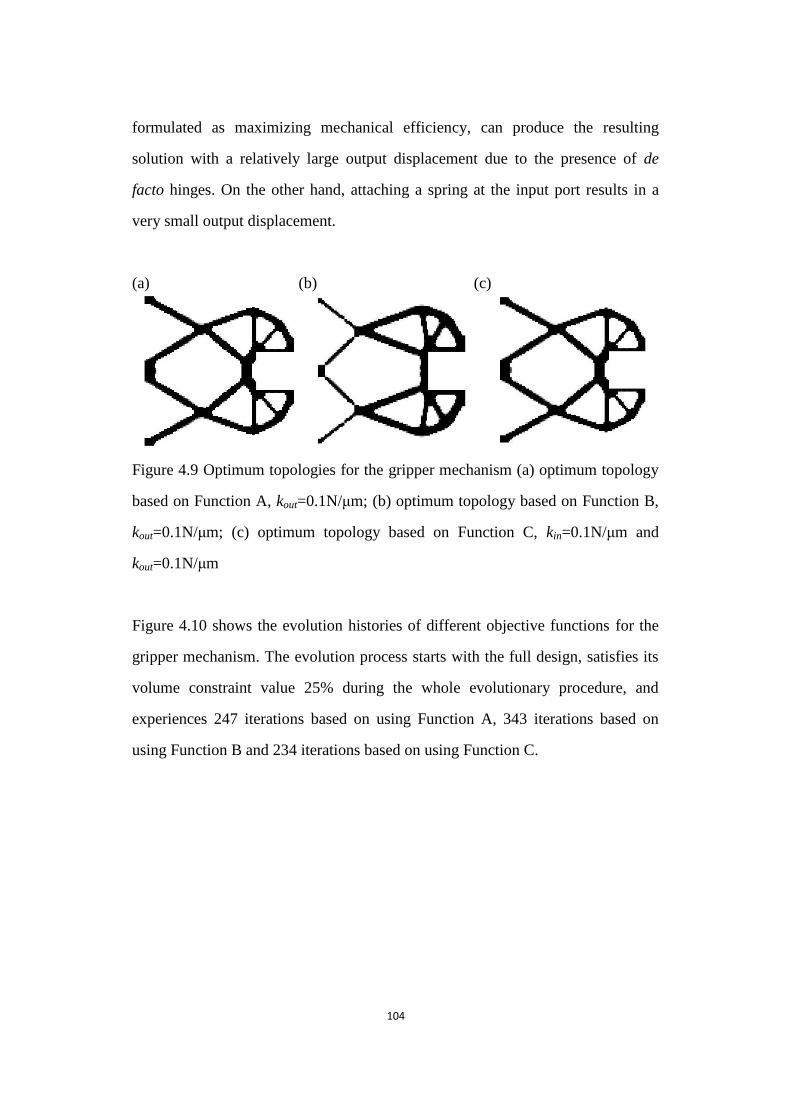
104
formulated as maximizing mechanical efficiency, can produce the resulting
solution with a relatively large output displacement due to the presence of de
facto hinges. On the other hand, attaching a spring at the input port results in a
very small output displacement.
(a) (b) (c)
Figure 4.9 Optimum topologies for the gripper mechanism
Figure 4.9 Optimum topologies for the gripper mechanism (a) optimum topology
based on Function A, kout=0.1N/μm; (b) optimum topology based on Function B,
kout=0.1N/μm; (c) optimum topology based on Function C, kin=0.1N/μm and
kout=0.1N/μm
Figure 4.10 shows the evolution histories of different objective functions for the
gripper mechanism. The evolution process starts with the full design, satisfies its
volume constraint value 25% during the whole evolutionary procedure, and
experiences 247 iterations based on using Function A, 343 iterations based on
using Function B and 234 iterations based on using Function C.
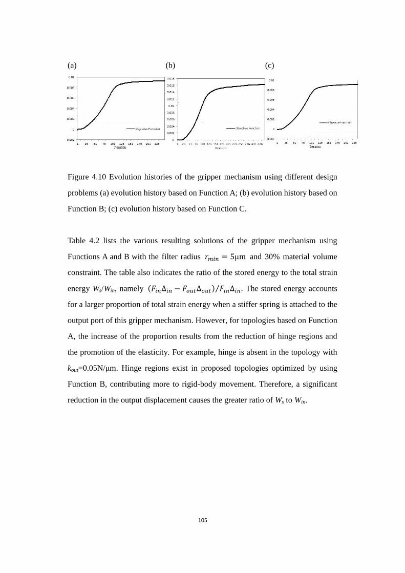
105
(a) (b) (c)
Figure 4.10 Evolution histories of the gripper mechanism using different design problems
Figure 4.10 Evolution histories of the gripper mechanism using different design
problems (a) evolution history based on Function A; (b) evolution history based on
Function B; (c) evolution history based on Function C.
Table 4.2 lists the various resulting solutions of the gripper mechanism using
Functions A and B with the filter radius 𝑟𝑚𝑖𝑛 = 5 and 30% material volume
constraint. The table also indicates the ratio of the stored energy to the total strain
energy Ws/Win, namely (𝐹𝑖𝑛∆𝑖𝑛 − 𝐹𝑜𝑢𝑡∆𝑜𝑢𝑡) 𝐹𝑖𝑛∆𝑖𝑛⁄ . The stored energy accounts
for a larger proportion of total strain energy when a stiffer spring is attached to the
output port of this gripper mechanism. However, for topologies based on Function
A, the increase of the proportion results from the reduction of hinge regions and
the promotion of the elasticity. For example, hinge is absent in the topology with
kout=0.05N/μm. Hinge regions exist in proposed topologies optimized by using
Function B, contributing more to rigid-body movement. Therefore, a significant
reduction in the output displacement causes the greater ratio of Ws to Win.
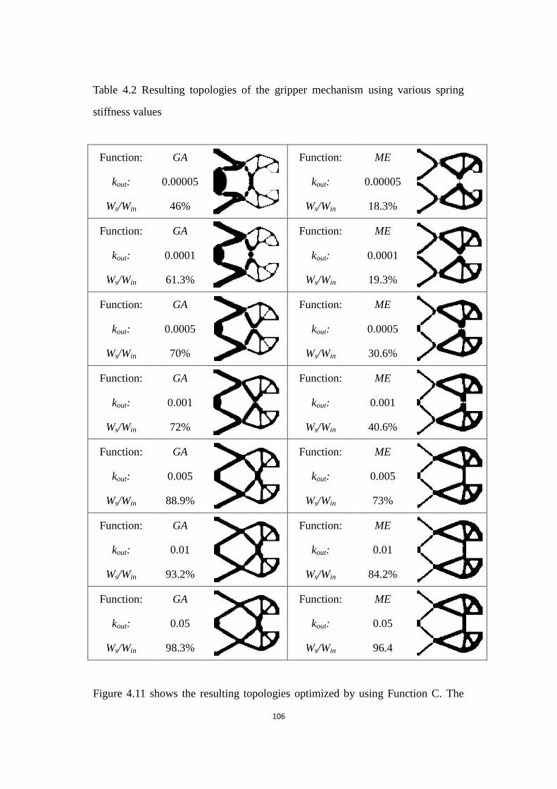
106
Table 4.2 Resulting topologies of the gripper mechanism using various spring
stiffness values
Function: GA
Function: ME
kout: 0.00005 kout: 0.00005
Ws/Win 46% Ws/Win 18.3%
Function: GA
Function: ME
kout: 0.0001 kout: 0.0001
Ws/Win 61.3% Ws/Win 19.3%
Function: GA
Function: ME
kout: 0.0005 kout: 0.0005
Ws/Win 70% Ws/Win 30.6%
Function: GA
Function: ME
kout: 0.001 kout: 0.001
Ws/Win 72% Ws/Win 40.6%
Function: GA
Function: ME
kout: 0.005 kout: 0.005
Ws/Win 88.9% Ws/Win 73%
Function: GA
Function: ME
kout: 0.01 kout: 0.01
Ws/Win 93.2% Ws/Win 84.2%
Function: GA
Function: ME
kout: 0.05 kout: 0.05
Ws/Win 98.3% Ws/Win 96.4
Figure 4.11 shows the resulting topologies optimized by using Function C. The
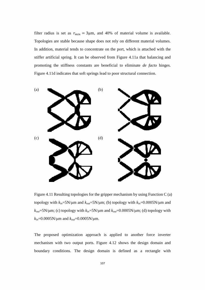
107
filter radius is set as 𝑟𝑚𝑖𝑛 = 3 , and 40% of material volume is available.
Topologies are stable because shape does not rely on different material volumes.
In addition, material tends to concentrate on the port, which is attached with the
stiffer artificial spring. It can be observed from Figure 4.11a that balancing and
promoting the stiffness constants are beneficial to eliminate de facto hinges.
Figure 4.11d indicates that soft springs lead to poor structural connection.
(a) (b)
(c) (d)
Figure 4.11 Resulting topologies for the gripper mechanism by using Function C
Figure 4.11 Resulting topologies for the gripper mechanism by using Function C (a)
topology with kin=5N/μm and kout=5N/μm; (b) topology with kin=0.0005N/μm and
kout=5N/μm; (c) topology with kin=5N/μm and kout=0.0005N/μm; (d) topology with
kin=0.0005N/μm and kout=0.0005N/μm.
The proposed optimization approach is applied to another force inverter
mechanism with two output ports. Figure 4.12 shows the design domain and
boundary conditions. The design domain is defined as a rectangle with
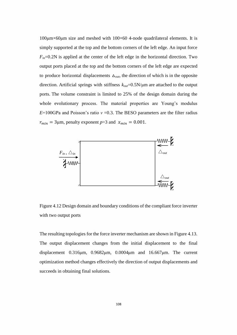
108
100μm×60μm size and meshed with 100×60 4-node quadrilateral elements. It is
simply supported at the top and the bottom corners of the left edge. An input force
Fin=0.2N is applied at the center of the left edge in the horizontal direction. Two
output ports placed at the top and the bottom corners of the left edge are expected
to produce horizontal displacements △out, the direction of which is in the opposite
direction. Artificial springs with stiffness kout=0.5N/μm are attached to the output
ports. The volume constraint is limited to 25% of the design domain during the
whole evolutionary process. The material properties are Young‟s modulus
E=100GPa and Poisson‟s ratio ν =0.3. The BESO parameters are the filter radius
𝑟𝑚𝑖𝑛 = 3 , penalty exponent p=3 and 𝑚𝑖𝑛 = 0 001.
Figure 4.12 Design domain and boundary conditions of the compliant force inverter with two output ports
Figure 4.12 Design domain and boundary conditions of the compliant force inverter
with two output ports
The resulting topologies for the force inverter mechanism are shown in Figure 4.13.
The output displacement changes from the initial displacement to the final
displacement 0.316μm, 0.9682μm, 0.0004μm and 16.667μm. The current
optimization method changes effectively the direction of output displacements and
succeeds in obtaining final solutions.
△out
△out Fin , △in
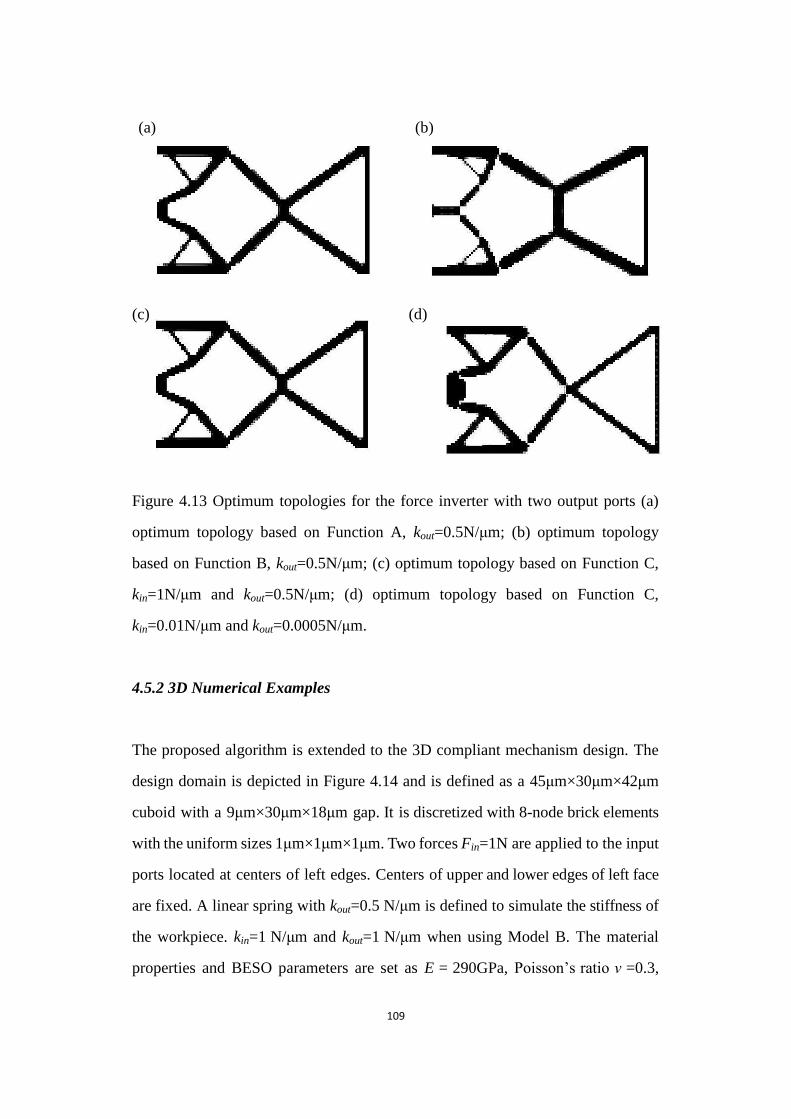
109
(a) (b)
(c) (d)
Figure 4.13 Optimum topologies for the force inverter with two output ports
Figure 4.13 Optimum topologies for the force inverter with two output ports (a)
optimum topology based on Function A, kout=0.5N/μm; (b) optimum topology
based on Function B, kout=0.5N/μm; (c) optimum topology based on Function C,
kin=1N/μm and kout=0.5N/μm; (d) optimum topology based on Function C,
kin=0.01N/μm and kout=0.0005N/μm.
4.5.2 3D Numerical Examples
The proposed algorithm is extended to the 3D compliant mechanism design. The
design domain is depicted in Figure 4.14 and is defined as a 45μm×30μm×42μm
cuboid with a 9μm×30μm×18μm gap. It is discretized with 8-node brick elements
with the uniform sizes 1μm×1μm×1μm. Two forces Fin=1N are applied to the input
ports located at centers of left edges. Centers of upper and lower edges of left face
are fixed. A linear spring with kout=0.5 N/μm is defined to simulate the stiffness of
the workpiece. kin=1 N/μm and kout=1 N/μm when using Model B. The material
properties and BESO parameters are set as E = 290GPa, Poisson‟s ratio ν =0.3,
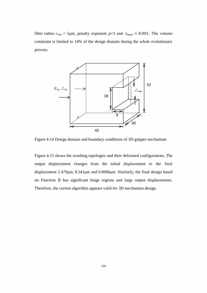
110
filter radius rmin = 5μm, penalty exponent p=3 and 𝑚𝑖𝑛 = 0 001. The volume
constraint is limited to 14% of the design domain during the whole evolutionary
process.
Figure 4.14 Design domain and boundary conditions of 3D gripper mechanism
Figure 4.14 Design domain and boundary conditions of 3D gripper mechanism
Figure 4.15 shows the resulting topologies and their deformed configurations. The
output displacement changes from the initial displacement to the final
displacement 2.479μm, 8.541μm and 0.0066μm. Similarly, the final design based
on Function B has significant hinge regions and large output displacements.
Therefore, the current algorithm appears valid for 3D mechanism design.
Fin, △in △out
18
45
9
30
42
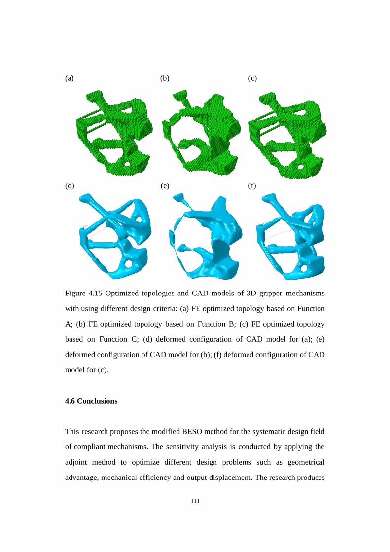
111
(a) (b) (c)
(d) (e) (f)
Figure 4.15 Optimized topologies and CAD models of 3D gripper mechanisms with using different design criteria
Figure 4.15 Optimized topologies and CAD models of 3D gripper mechanisms
with using different design criteria: (a) FE optimized topology based on Function
A; (b) FE optimized topology based on Function B; (c) FE optimized topology
based on Function C; (d) deformed configuration of CAD model for (a); (e)
deformed configuration of CAD model for (b); (f) deformed configuration of CAD
model for (c).
4.6 Conclusions
This research proposes the modified BESO method for the systematic design field
of compliant mechanisms. The sensitivity analysis is conducted by applying the
adjoint method to optimize different design problems such as geometrical
advantage, mechanical efficiency and output displacement. The research produces
112
various resulting designs with the change in the springs‟ constants. Examples
proposed by the new BESO procedure demonstrate the springs‟ effects in the
optimal design of compliant mechanisms. Some conclusions can be drawn in this
section.
Firstly, numerical examples have demonstrated the capability and validity of the
new BESO algorithm. Secondly, there is little undesirable „grey area‟ in resulting
designs. Thirdly, resulting topologies can produce relatively larger output
displacement due to the presence of de facto hinge regions when using the
optimization problem of maximizing mechanical efficiency. Fourthly, when
attaching a stiffer artificial spring to input port, the geometrical advantage and
mechanical efficiency decrease, and resulting topology become simpler. In
addition, the former tends to be an exponential decrease, but the mechanical
efficiency shows a linear decrease. Fifthly, for topologies based on using the
optimization problem of maximizing output displacement, balancing and
promoting stiffness constants are beneficial to eliminate de facto hinges. Soft
springs can lead to poor structural connection. Overall, spring stiffness has strong
effects on the optimal design of compliant mechanisms.
References
Ananthasuresh, G. K., 2003. Optimal Synthesis Methods for MEMS, Kluwer Academic Publisher,
Boston.
Ansola, R., Veguería, E., Canales, J. and Tárrago, J. A., 2007, "A simple evolutionary topology
optimization procedure for compliant mechanism design ", Finite Elements in Analysis and
Design 44(1-2), 53-62.
Frecker, M. I., Ananthasuresh, G. K., Nishiwaka, S., Kikuchi, N. and Kota, S., 1997, "Topological
Synthesis of Compliant Mechanisms Using Multi-Criteria Optimization", Journal of
113
Mechanical Design 119(2), 238-245.
Lin, J., Luo, Z. and Tong, L., 2010, "A new multi-objective programming scheme for topology
optimization of compliant mechanisms", Structural and Multidisciplinary Optimization
40(1-6), 241-255.
Luo, Z., Tong, L., Wang, M. Y. and Wang, s., 2007, "Shape and topology optimization of compliant
mechanisms using a parameterization level set method", Journal of Computational Physics
227(1), 680-705.
Saxena, A. and Ananthasuresh, G. K., 2001, "Topology optimization of compliant mechanisms with
strength considerations", Mechanics of Structures and Machines 29(2), 199-221.
Sigmund, O., 1997, "On the design of compliant mechanisms using topology optimization",
Mechanics of Structures and Machines 25(4), 493-524.
Wang, M. Y., 2009, "Mechanical and geometric advantages in compliant mechanism optimization",
Frontiers of Mechanical Engineering in China 4(3), 229-241.
114
Chapter 5
Desired Structural Stiffness in
Topology Design of Linear Compliant
Mechanisms
115
Chapter Overview
The dissertation has applied the modified BESO method to the optimal design of
compliant mechanisms and demonstrated the capability of solving several
optimization problems. This chapter presents a new algorithm for the effective
control of the desired structural stiffness in the topology design of linear
compliant mechanisms. The design problem is reformulated as maximizing the
flexibility of the compliant mechanisms subject to the mean compliance constraint,
considering the mechanism flexibility and structural stiffness simultaneously.
This research employs the modified BESO method, in which element densities are
gradually switched before a convergent solution and material volume is gradually
reduced until the prescribed volume. Several 2D and 3D examples are then
presented to demonstrate the effectiveness of the proposed BESO method. Finally,
this research summarizes the theory of flexibility and hinge-related properties of
optimized compliant mechanisms.
5.1 Optimization Problem and Structural Analysis
Generally, an efficient compliant mechanism should be flexible enough to
produce the expected kinematic motion (flexibility) but should also be stiff
enough to resist external forces (stiffness). As shown in Figure 4.1a, the
performance characteristics of flexibility and stiffness for a compliant mechanism
can be quantified using relationships among the applied forces, the resulting
displacements at the input port of the mechanism, and the resulting displacements
and reaction forces at the output port of the mechanism.
The topology optimization problem has been formulated in a number of
alternative ways through the use of assorted objective and constraint functions due

116
to the inherent multi-objective performance demand. In the light of the resulting
topologies outlined in the previous chapter, designing compliant mechanisms using
topology optimization methods typically results in de facto hinge regions in the
design models due to the problem formulation. The existence of de facto hinge
regions makes compliant mechanisms function as rigid-link mechanisms so as to
maximize their capability of transferring kinematic motion. Due to the difficulties
in manufacturing reliable hinges especially for micro-scale mechanical systems,
designing monolithic and hinge-free compliant mechanisms has attracted extensive
attention and undergone considerable development in recent years.
Among previous techniques, reformulating the problem as a multi-criteria
optimization might be an effective way for entirely circumventing de facto hinge
regions which generally lie along the force path from the mechanism input port to
the output port. For example, simultaneously maximizing the flexibility and
minimizing the stiffness of the input-restrained structure can achieve hinge-free
compliant mechanisms (Frecker et al., 1997; Rahmatalla and Swan, 2005), and
the resulting compliant mechanisms are also stiff and can resist the additional load
exerted by the workpiece once it has been secured. Recently, Zhu et al. (2013)
incorporated this approach to optimize hinge-free compliant mechanisms with
multiple outputs. Nevertheless, it should be noted that the stiffness of a compliant
mechanism is only equivalent to that of the input-restrained structure when the
stiffness of the workpiece tends to infinity.
With a given stiffness of the workpiece, the formation of de facto hinge regions
must be correlated with the structural stiffness of compliant mechanisms.
However, there is no related literature to reveal the inherent relationship between
the formation of de facto hinge regions and the structural stiffness. This
dissertation proposes a new BESO method for optimally designing the flexibility
117
of compliant mechanisms by altering the desired structural stiffness, which
includes the influence of external loads exerted by the workpiece.
As shown in Figure 4.1a, consider the design domain of a compliant mechanism
where Fin is the applied force at the input port and △out is the expected output
displacement at the output port. A spring with a constant stiffness, kout, is used to
simulate the interaction between the workpiece and the compliant mechanism. △in
is the resulting displacement at the input port and Fout = kout×△out is the output
force. From Section 4.1, we can note that the displacement field of the mechanism
can be obtained through coupling the displacements caused by the input unit
dummy load case (refer to Figure 4.1b) and the output unit dummy load case
(refer to Figure 4.1c) via a linear elastic fashion. △11 and △21 denote the
displacements at the input port and the output port of the input unit dummy load
case, and △12 and △22 represent the displacements at the input port and the output
port of the output unit dummy load case. The input displacement △in and output
displacement △out can be found in Equation 4.3 through the superposition of the
input unit dummy load case and the output unit dummy load case. They can be
explicitly expressed by Equation 4.6.
The performance of compliant mechanisms can be measured by the characteristics
of their flexibility and structural stiffness. The flexibility of a compliant mechanism
can be quantified by the resulting displacement at the output port, △out, which
reflects the force or motion transmission ability of compliant mechanisms. While
the structural stiffness or mean compliance is one of key factors that must be taken
into account in the design of structures, the mean compliance of the compliant
mechanism, C, can be defined as the work done by external forces as
𝐶 =𝐹𝑖𝑛∆𝑖𝑛2
−𝐹𝑜𝑢𝑡∆𝑜𝑢𝑡
2=𝐹𝑖𝑛∆𝑖𝑛2
−𝑘 ∆𝑜𝑢𝑡
2
2
118
= 1 2∆11+ 1∆11∆22𝑘 − 1∆21∆12𝑘
2( 2+∆22𝑘 )−𝑘
2(
2∆21
2+∆22𝑘 )2
(5.1)
It can be seen that the mean compliance considers the influence of the stiffness of the
workpiece, which exerts external forces to the compliant mechanism. It should be
noted that the definition of the above mean compliance is different from the standard
mean compliance which is simply 𝐹𝑖𝑛∆𝑖𝑛 (Lin et al., 2010) or the input-restrained
compliance (Rahmatalla and Swan, 2005).
Instead of using the combination of the flexibility and stiffness as a single objective
function (Frecker et al., 1997; Rahmatalla and Swan, 2005; Ansola et al., 2007) or
multiple objective functions (Lau et al., 2001; Lin et al., 2010), the research
reformulates the design of a compliant mechanism by maximizing the output
displacement at the output port, and constraining its mean compliance and the
amount of structural material that can be used. Mathematically, the optimization
problem of a compliant mechanism is expressed by
Maximize ( ) = ∆𝑜𝑢𝑡 (5.2)
Subject to: 𝐶 ≤ 𝐶∗
𝑉∗ − ∑ 𝑉𝑒𝑁𝑒=1 𝑒 = 0
𝑒 = 𝑒,1, 𝑒,2, … , 𝑜𝑟 𝑒,𝑚
where C* and V
* are the prescribed mean compliance and volume of the compliant
mechanism respectively. The design domain is discretized with finite elements, and
the volumetric density of each element, xe, is used as the design variable.
5.2 Sensitivity Number
In order to satisfy the additional constraint, the prescribed mean compliance, the
119
original objective function is modified by adding the constraint and introducing a
Lagrange multiplier λ (Huang and Xie, 2010a). The modified objective function is
expressed by
Maximize ( ) = ∆𝑜𝑢𝑡 + × (𝐶∗ − 𝐶) (5.3)
Equation 5.3 points out that the modified objective function is equivalent to the
original one if the mean compliance is equal to its prescribed value. Otherwise λ = 0
if 𝐶 < 𝐶∗, which means the compliance constraint is already satisfied, and λ equals
to a certain value if 𝐶 > 𝐶∗ , which means the constraint algorithm should
minimize the mean compliance (or maximize −𝐶) to satisfy the constraint in the
later iterations. Therefore, the Lagrange multiplier is employed to design compliant
mechanisms with the compromise between maximizing △out and minimizing C so
as to satisfy the compliance constraint.
Consequently, the sensitivity number of the modified objective function can be
established as
𝛼𝑒 =𝑑ℎ
𝑑𝑥𝑒= ∆𝑜
𝑥𝑒−
𝑑𝐶
𝑑𝑥𝑒= ∆𝑜
𝑥𝑒− (
𝑖𝑛
2
∆𝑖𝑛
𝑥𝑒− 𝑘 ∆𝑜𝑢𝑡
∆𝑜
𝑥𝑒) (5.4)
The derivatives of the input and output displacements can be obtained by using
Equations 4.18 and 4.19. The sensitivity of displacements ∆𝑖𝑗 can be found in
Equation 4.16.
5.3 Determination of Lagrange Multiplier
For the numerical implementation, the Lagrange multiplier λ can be defined as
= (1 − 𝜔) 𝜔⁄ , the objective function can be rewritten as
120
Maximize ( ) = 𝜔∆𝑜𝑢𝑡 + (1 − 𝜔)(𝐶∗ − 𝐶) (5.5)
where ω is a constant ranging from 0 to 1 which will be determined according to the
compliance constraint. The relative ranking of the sensitivity number is sorted
according to Equation 5.4.
Specifically, the volume constraint is firstly satisfied in the algorithm. The
procedure should determine appropriately the volume threshold of sensitivity
numbers, 𝛼𝑡ℎ . Then the elemental density is switched from 𝑒,𝑗 to 𝑒,𝑗−1 if
𝛼𝑒 > 𝛼𝑡ℎ, or from 𝑒,𝑗 to 𝑒,𝑗+1 if 𝛼𝑒 < 𝛼𝑡ℎ in the proposed BESO algorithm.
Secondly, to satisfy the compliance constraint in the algorithm, the variation of
the compliance ∆𝐶 is measured according to the variation of the design variables.
The mean compliance in the next iteration Ck+1
can be approximately estimated by
Equation 5.6, in which Ck represents the value of the mean compliance in the
current iteration and ∆ 𝑒 = 𝑒,𝑗−1 − 𝑒,𝑗 = 𝑒,𝑗 − 𝑒,𝑗+1, namely the difference of
two adjacent densities for each element. Here, ∆xe is set as 0.02, which means a
number of intermediate element densities.
𝐶𝑘+1 𝐶𝑘 + ∑𝜕𝐶
𝜕𝑥𝑒× ∆ 𝑒𝑒 (5.6)
Finally, the Lagrange multiplier can be determined by comparing the approximate
value and the maximum acceptable value. Therefore, 𝜔 will be replaced by
�̂� = (𝜔 + 𝜔𝑙𝑜𝑤𝑒𝑟) 2⁄ if 𝐶𝑘+1 > 𝐶∗. At the same time, 𝜔 will be selected as the
upper bound 𝜔𝑢𝑝𝑝𝑒𝑟 . Otherwise the procedure will update 𝜔 with �̂� =
(𝜔 + 𝜔𝑢𝑝𝑝𝑒𝑟) 2⁄ if 𝐶𝑘+1 < 𝐶∗ . Also, 𝜔 will be chosen as the lower bound
𝜔𝑙𝑜𝑤𝑒𝑟. With �̂� is continuously updated, the above procedure is repeated until
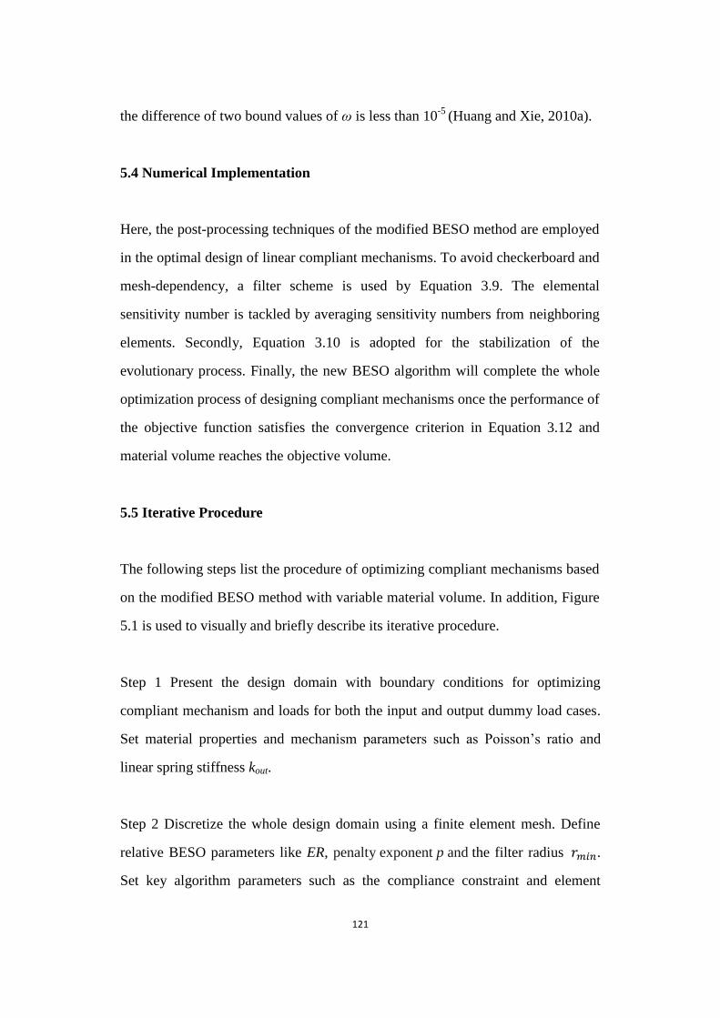
121
the difference of two bound values of ω is less than 10-5
(Huang and Xie, 2010a).
5.4 Numerical Implementation
Here, the post-processing techniques of the modified BESO method are employed
in the optimal design of linear compliant mechanisms. To avoid checkerboard and
mesh-dependency, a filter scheme is used by Equation 3.9. The elemental
sensitivity number is tackled by averaging sensitivity numbers from neighboring
elements. Secondly, Equation 3.10 is adopted for the stabilization of the
evolutionary process. Finally, the new BESO algorithm will complete the whole
optimization process of designing compliant mechanisms once the performance of
the objective function satisfies the convergence criterion in Equation 3.12 and
material volume reaches the objective volume.
5.5 Iterative Procedure
The following steps list the procedure of optimizing compliant mechanisms based
on the modified BESO method with variable material volume. In addition, Figure
5.1 is used to visually and briefly describe its iterative procedure.
Step 1 Present the design domain with boundary conditions for optimizing
compliant mechanism and loads for both the input and output dummy load cases.
Set material properties and mechanism parameters such as Poisson‟s ratio and
linear spring stiffness kout.
Step 2 Discretize the whole design domain using a finite element mesh. Define
relative BESO parameters like ER, penalty exponent p and the filter radius 𝑟𝑚𝑖𝑛.
Set key algorithm parameters such as the compliance constraint and element

122
densities.
Step 3 Carry out a finite element analysis and output the displacement fields from
both dummy load cases.
Step 4 Calculate sensitivity numbers with the help of Equation 5.4,
Step 5 Determine appropriately the volume threshold of sensitivity numbers for
achieving the volume constraint.
Step 6 Determine the Lagrange multiplier based on the procedure detailed in
Section 5.3
Step 7 Update sensitivity numbers by the filter scheme Equation 3.9 and average
with their historical information by Equation 3.10.
Step 8 Reset and rank all design variables, and set the threshold of the sensitivity
number, 𝛼𝑡ℎ , which is determined according to the target material volume
constraint Equation 3.11 and 𝑉∗ = ∑ 𝑉𝑒 𝑒 ( 𝑒 = 𝑒,1, 𝑒,2, … , 𝑜𝑟 𝑒,𝑚)𝑛𝑒=1 . The
corresponding density variable of eth element should be switched from 𝑒,𝑗 to
𝑒,𝑗−1 if 𝛼𝑒 > 𝛼𝑡ℎ, or from 𝑒,𝑗 to 𝑒,𝑗+1 if 𝛼𝑒 < 𝛼𝑡ℎ
Step 9 Repeat Steps 3-8 until both the volume fraction reaches objective volume
and the performance of objective function satisfies its convergence criteria
according to Equation 3.12.
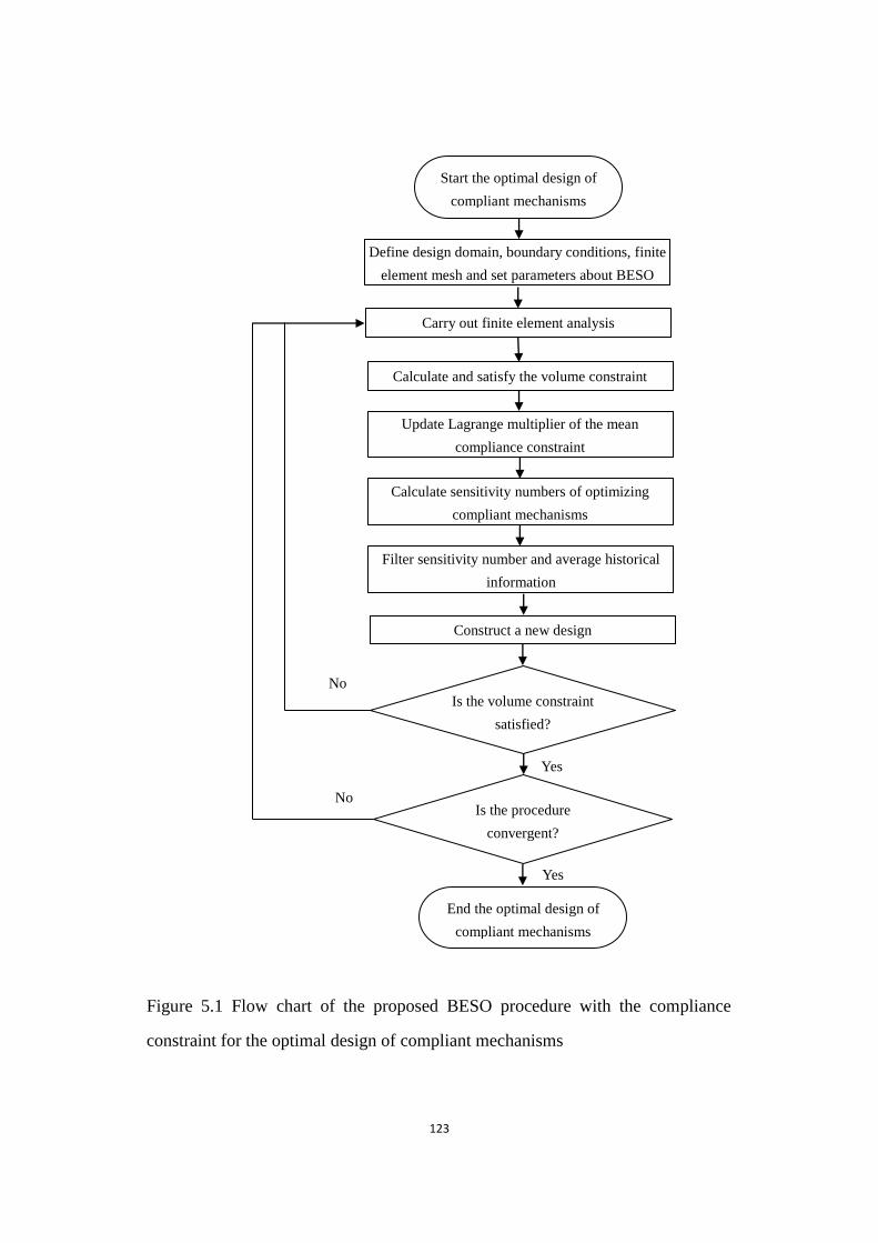
123
Figure 5.1 Flow chart of the proposed BESO procedure with the compliance constraint for the optimal design of compliant mechanisms
Figure 5.1 Flow chart of the proposed BESO procedure with the compliance
constraint for the optimal design of compliant mechanisms
No
No
Yes
Yes
End the optimal design of
compliant mechanisms
Start the optimal design of
compliant mechanisms
Define design domain, boundary conditions, finite
element mesh and set parameters about BESO
Carry out finite element analysis
Calculate sensitivity numbers of optimizing
compliant mechanisms
Filter sensitivity number and average historical
information
Calculate and satisfy the volume constraint
Construct a new design
Is the volume constraint
satisfied?
Is the procedure
convergent?
Update Lagrange multiplier of the mean
compliance constraint
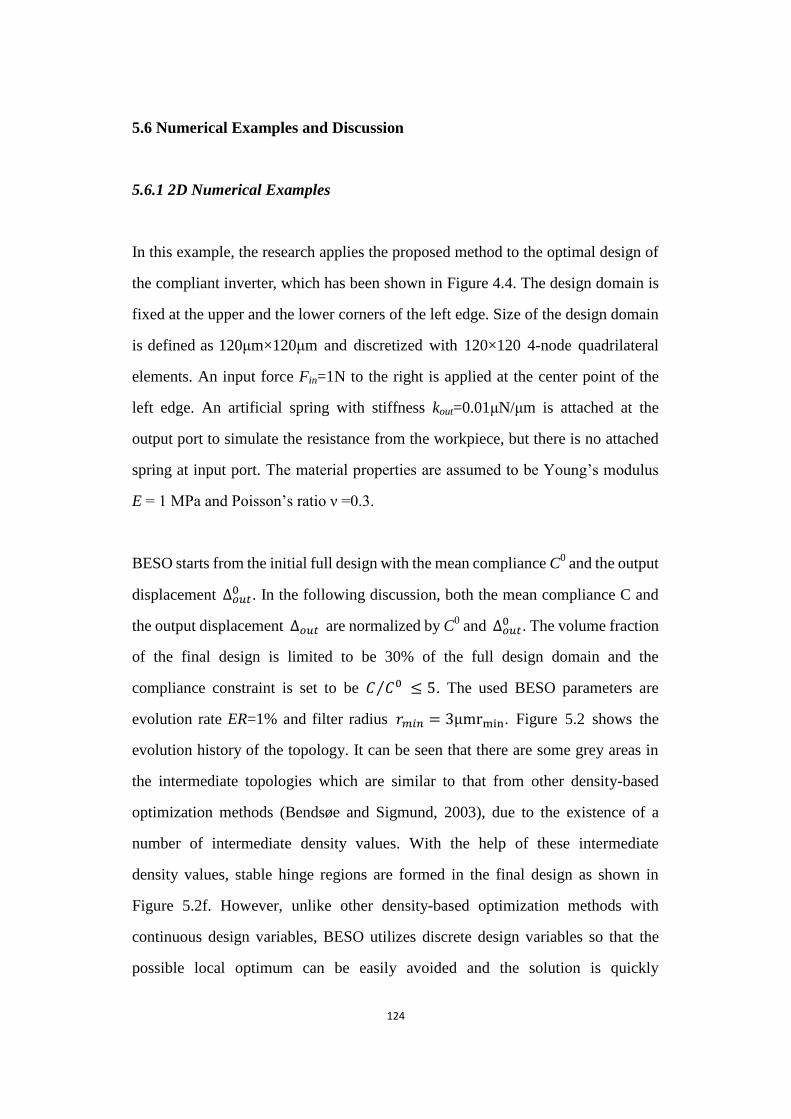
124
5.6 Numerical Examples and Discussion
5.6.1 2D Numerical Examples
In this example, the research applies the proposed method to the optimal design of
the compliant inverter, which has been shown in Figure 4.4. The design domain is
fixed at the upper and the lower corners of the left edge. Size of the design domain
is defined as 120μm×120μm and discretized with 120×120 4-node quadrilateral
elements. An input force Fin=1N to the right is applied at the center point of the
left edge. An artificial spring with stiffness kout=0.01μN/μm is attached at the
output port to simulate the resistance from the workpiece, but there is no attached
spring at input port. The material properties are assumed to be Young‟s modulus
E = 1 MPa and Poisson‟s ratio ν =0.3.
BESO starts from the initial full design with the mean compliance C0 and the output
displacement ∆𝑜𝑢𝑡0 . In the following discussion, both the mean compliance C and
the output displacement ∆𝑜𝑢𝑡 are normalized by C0 and ∆𝑜𝑢𝑡
0 . The volume fraction
of the final design is limited to be 30% of the full design domain and the
compliance constraint is set to be 𝐶 𝐶0⁄ ≤ 5. The used BESO parameters are
evolution rate ER=1% and filter radius 𝑟𝑚𝑖𝑛 = 3 . Figure 5.2 shows the
evolution history of the topology. It can be seen that there are some grey areas in
the intermediate topologies which are similar to that from other density-based
optimization methods (Bendsøe and Sigmund, 2003), due to the existence of a
number of intermediate density values. With the help of these intermediate
density values, stable hinge regions are formed in the final design as shown in
Figure 5.2f. However, unlike other density-based optimization methods with
continuous design variables, BESO utilizes discrete design variables so that the
possible local optimum can be easily avoided and the solution is quickly

125
convergent to an almost black and white design. Figure 5.3 shows the evolution
histories of the output displacement, mean compliance and volume fraction. It can
be seen that the magnitude of the output displacement gradually increases to its
negative maximum value until both the volume and compliance constraints are
stably satisfied. The convergent solution is achieved with 209 iterations under the
convergence factor of 0.1% for both the output displacement and the mean
compliance.
(a) (b) (c)
(d) (e) (f)
Figure 5.2 Evolution history of the topology for the compliant inverter
Figure 5.2 Evolution history of the topology for the compliant inverter (a) initial
topology; (b) topology at Iteration 50; (c) topology at Iteration 100; (d) topology at
Iteration 150; (e) topology at Iteration 200; (f) resulting topology.
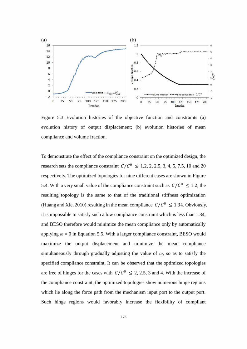
126
(a) (b)
Figure 5.3 Evolution histories of the objective function and constraints
Figure 5.3 Evolution histories of the objective function and constraints (a)
evolution history of output displacement; (b) evolution histories of mean
compliance and volume fraction.
To demonstrate the effect of the compliance constraint on the optimized design, the
research sets the compliance constraint 𝐶 𝐶0⁄ ≤ 1.2, 2, 2.5, 3, 4, 5, 7.5, 10 and 20
respectively. The optimized topologies for nine different cases are shown in Figure
5.4. With a very small value of the compliance constraint such as 𝐶 𝐶0⁄ ≤ 1 2, the
resulting topology is the same to that of the traditional stiffness optimization
(Huang and Xie, 2010) resulting in the mean compliance 𝐶 𝐶0⁄ ≤ 1 34. Obviously,
it is impossible to satisfy such a low compliance constraint which is less than 1.34,
and BESO therefore would minimize the mean compliance only by automatically
applying ω = 0 in Equation 5.5. With a larger compliance constraint, BESO would
maximize the output displacement and minimize the mean compliance
simultaneously through gradually adjusting the value of ω, so as to satisfy the
specified compliance constraint. It can be observed that the optimized topologies
are free of hinges for the cases with 𝐶 𝐶0⁄ ≤ 2, 2.5, 3 and 4. With the increase of
the compliance constraint, the optimized topologies show numerous hinge regions
which lie along the force path from the mechanism input port to the output port.
Such hinge regions would favorably increase the flexibility of compliant

127
mechanisms to efficiently transfer the energy/motion from the input port to the
output port. However these hinge regions would greatly decreases the stiffness of
the compliant mechanism, apart from the existing difficulties in manufacturing.
(a) (b) (c)
(d) (e) (f)
(g) (h) (i)
Figure 5.4 Optimized topologies and output displacements of the compliant inverters for various compliance constraints
Figure 5.4 Optimized topologies and output displacements of the compliant
inverters for various compliance constraints (a) 𝐶 𝐶0⁄ ≤ 1 2 and ∆𝑜𝑢𝑡 ∆𝑜𝑢𝑡0⁄ = 0;
(b) 𝐶 𝐶0⁄ ≤ 2 and ∆𝑜𝑢𝑡 ∆𝑜𝑢𝑡0⁄ = −2 015 ; (c) 𝐶 𝐶0⁄ ≤ 2 5 and ∆𝑜𝑢𝑡 ∆𝑜𝑢𝑡
0⁄ =
−3 747 ; (d) 𝐶 𝐶0⁄ ≤ 3 and ∆𝑜𝑢𝑡 ∆𝑜𝑢𝑡0⁄ = −6 108 ; (e) 𝐶 𝐶0⁄ ≤ 4 and
∆𝑜𝑢𝑡 ∆𝑜𝑢𝑡0⁄ = −10 766; (f) 𝐶 𝐶0⁄ ≤ 5 and ∆𝑜𝑢𝑡 ∆𝑜𝑢𝑡
0⁄ = −14 806; (g) 𝐶 𝐶0⁄ ≤
7 5 and ∆𝑜𝑢𝑡 ∆𝑜𝑢𝑡0⁄ = −21 515; (h) 𝐶 𝐶0⁄ ≤ 10 and ∆𝑜𝑢𝑡 ∆𝑜𝑢𝑡
0⁄ = −26 253; (i)
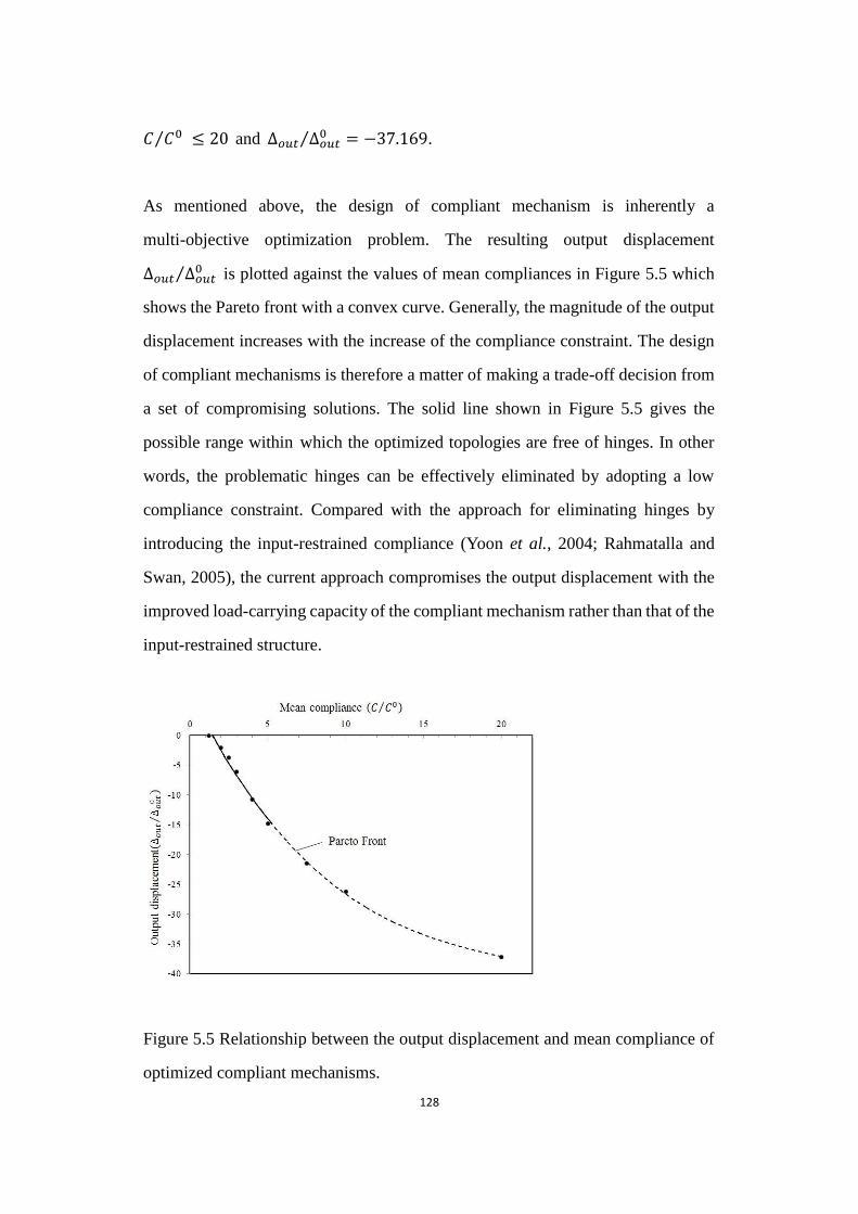
128
𝐶 𝐶0⁄ ≤ 20 and ∆𝑜𝑢𝑡 ∆𝑜𝑢𝑡0⁄ = −37 169.
As mentioned above, the design of compliant mechanism is inherently a
multi-objective optimization problem. The resulting output displacement
∆𝑜𝑢𝑡 ∆𝑜𝑢𝑡0⁄ is plotted against the values of mean compliances in Figure 5.5 which
shows the Pareto front with a convex curve. Generally, the magnitude of the output
displacement increases with the increase of the compliance constraint. The design
of compliant mechanisms is therefore a matter of making a trade-off decision from
a set of compromising solutions. The solid line shown in Figure 5.5 gives the
possible range within which the optimized topologies are free of hinges. In other
words, the problematic hinges can be effectively eliminated by adopting a low
compliance constraint. Compared with the approach for eliminating hinges by
introducing the input-restrained compliance (Yoon et al., 2004; Rahmatalla and
Swan, 2005), the current approach compromises the output displacement with the
improved load-carrying capacity of the compliant mechanism rather than that of the
input-restrained structure.
Figure 5.5 Relationship between the output displacement and mean compliance of optimized compliant mechanisms.
Figure 5.5 Relationship between the output displacement and mean compliance of
optimized compliant mechanisms.
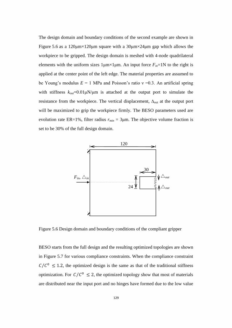
129
The design domain and boundary conditions of the second example are shown in
Figure 5.6 as a 120μm×120μm square with a 30μm×24μm gap which allows the
workpiece to be gripped. The design domain is meshed with 4-node quadrilateral
elements with the uniform sizes 1μm×1μm. An input force Fin=1N to the right is
applied at the center point of the left edge. The material properties are assumed to
be Young‟s modulus E = 1 MPa and Poisson‟s ratio ν =0.3. An artificial spring
with stiffness kout=0.01μN/μm is attached at the output port to simulate the
resistance from the workpiece. The vertical displacement, ∆out at the output port
will be maximized to grip the workpiece firmly. The BESO parameters used are
evolution rate ER=1%, filter radius rmin = 3μm. The objective volume fraction is
set to be 30% of the full design domain.
Figure 5.6 Design domain and boundary conditions of the compliant gripper
Figure 5.6 Design domain and boundary conditions of the compliant gripper
BESO starts from the full design and the resulting optimized topologies are shown
in Figure 5.7 for various compliance constraints. When the compliance constraint
𝐶 𝐶0⁄ ≤ 1 2, the optimized design is the same as that of the traditional stiffness
optimization. For 𝐶 𝐶0⁄ ≤ 2, the optimized topology show that most of materials
are distributed near the input port and no hinges have formed due to the low value
120
Fin, △in △out
△out 24
30
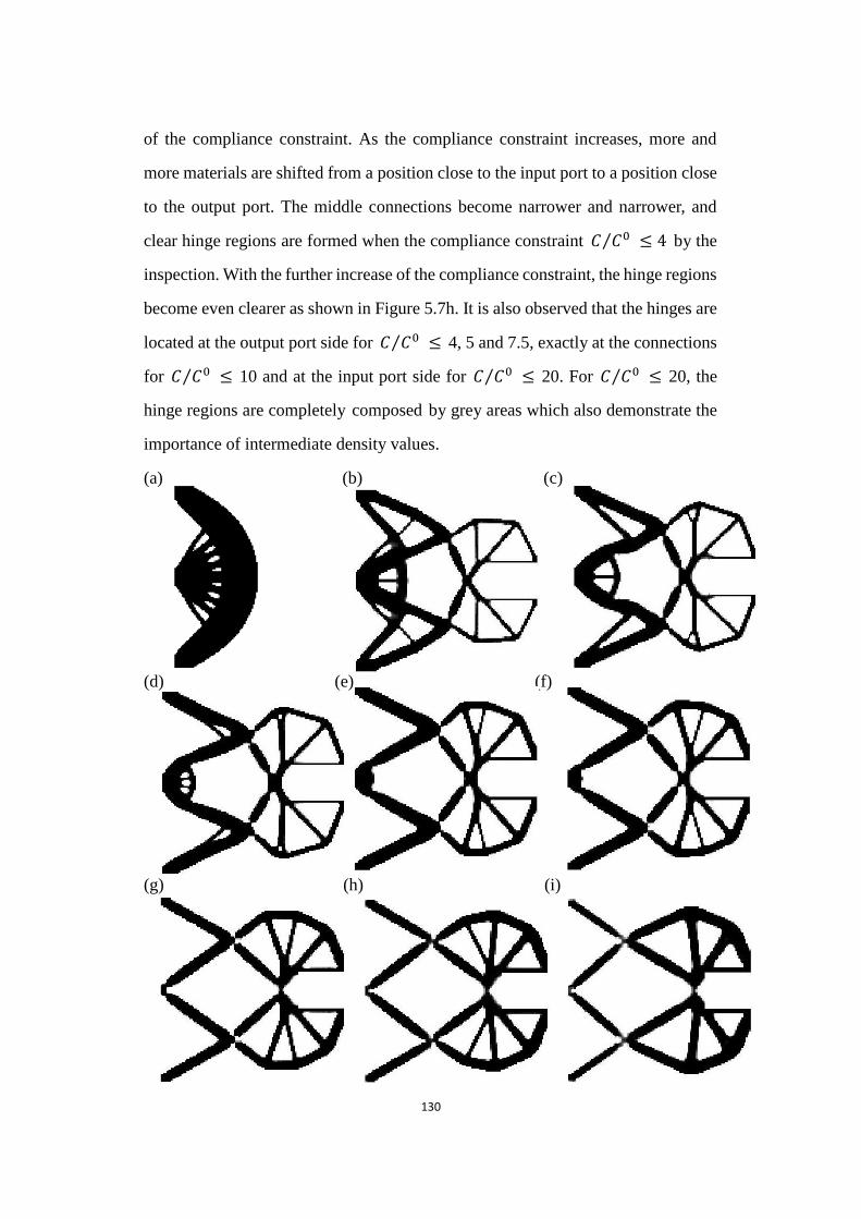
130
of the compliance constraint. As the compliance constraint increases, more and
more materials are shifted from a position close to the input port to a position close
to the output port. The middle connections become narrower and narrower, and
clear hinge regions are formed when the compliance constraint 𝐶 𝐶0⁄ ≤ 4 by the
inspection. With the further increase of the compliance constraint, the hinge regions
become even clearer as shown in Figure 5.7h. It is also observed that the hinges are
located at the output port side for 𝐶 𝐶0⁄ ≤ 4, 5 and 7.5, exactly at the connections
for 𝐶 𝐶0⁄ ≤ 10 and at the input port side for 𝐶 𝐶0⁄ ≤ 20. For 𝐶 𝐶0⁄ ≤ 20, the
hinge regions are completely composed by grey areas which also demonstrate the
importance of intermediate density values.
(a) (b) (c)
(d) (e) (f)
(g) (h) (i)
Figure 5.7 Optimized topologies and output displacements of the compliant grippers for various compliance constraints
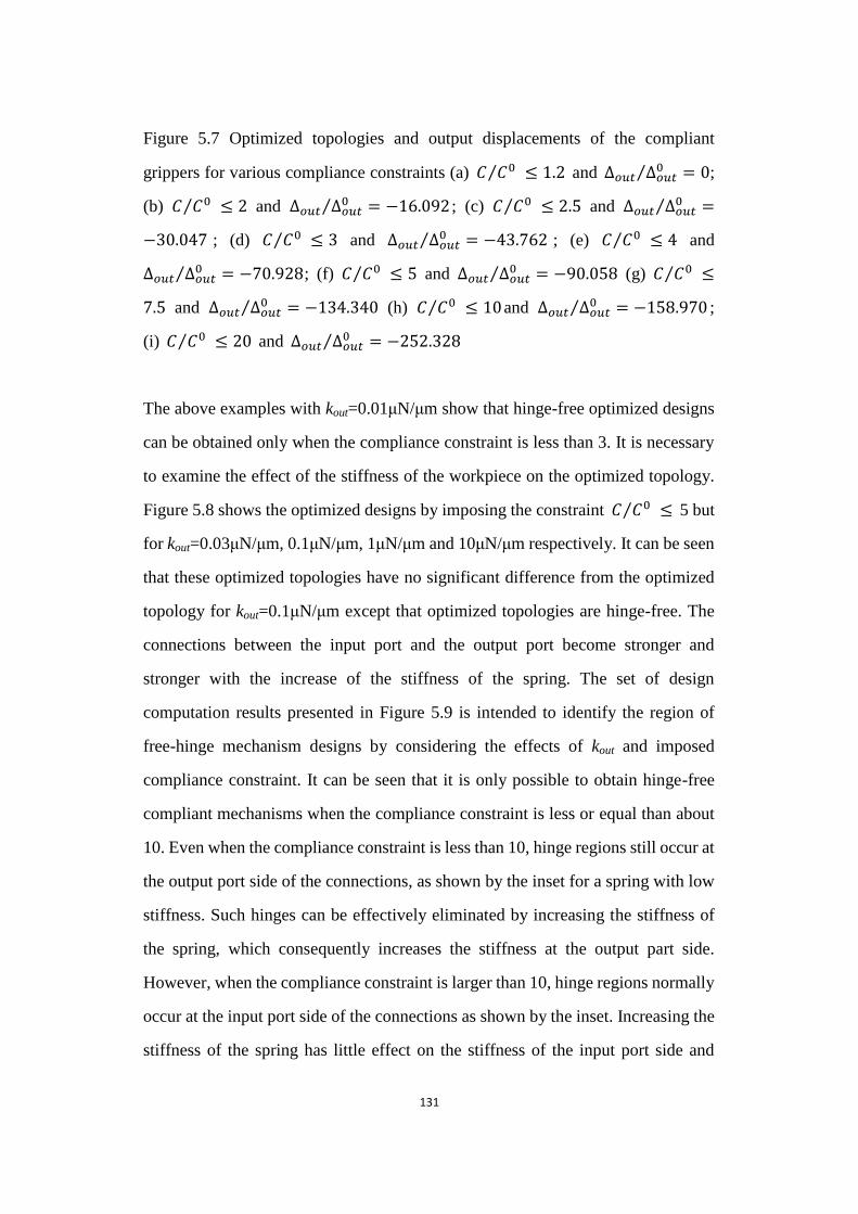
131
Figure 5.7 Optimized topologies and output displacements of the compliant
grippers for various compliance constraints (a) 𝐶 𝐶0⁄ ≤ 1 2 and ∆𝑜𝑢𝑡 ∆𝑜𝑢𝑡0⁄ = 0;
(b) 𝐶 𝐶0⁄ ≤ 2 and ∆𝑜𝑢𝑡 ∆𝑜𝑢𝑡0⁄ = −16 092 ; (c) 𝐶 𝐶0⁄ ≤ 2 5 and ∆𝑜𝑢𝑡 ∆𝑜𝑢𝑡
0⁄ =
−30 047 ; (d) 𝐶 𝐶0⁄ ≤ 3 and ∆𝑜𝑢𝑡 ∆𝑜𝑢𝑡0⁄ = −43 762 ; (e) 𝐶 𝐶0⁄ ≤ 4 and
∆𝑜𝑢𝑡 ∆𝑜𝑢𝑡0⁄ = −70 928; (f) 𝐶 𝐶0⁄ ≤ 5 and ∆𝑜𝑢𝑡 ∆𝑜𝑢𝑡
0⁄ = −90 058 (g) 𝐶 𝐶0⁄ ≤
7 5 and ∆𝑜𝑢𝑡 ∆𝑜𝑢𝑡0⁄ = −134 340 (h) 𝐶 𝐶0⁄ ≤ 10and ∆𝑜𝑢𝑡 ∆𝑜𝑢𝑡
0⁄ = −158 970 ;
(i) 𝐶 𝐶0⁄ ≤ 20 and ∆𝑜𝑢𝑡 ∆𝑜𝑢𝑡0⁄ = −252 328
The above examples with kout=0.01μN/μm show that hinge-free optimized designs
can be obtained only when the compliance constraint is less than 3. It is necessary
to examine the effect of the stiffness of the workpiece on the optimized topology.
Figure 5.8 shows the optimized designs by imposing the constraint 𝐶 𝐶0⁄ ≤ 5 but
for kout=0.03μN/μm, 0.1μN/μm, 1μN/μm and 10μN/μm respectively. It can be seen
that these optimized topologies have no significant difference from the optimized
topology for kout=0.1μN/μm except that optimized topologies are hinge-free. The
connections between the input port and the output port become stronger and
stronger with the increase of the stiffness of the spring. The set of design
computation results presented in Figure 5.9 is intended to identify the region of
free-hinge mechanism designs by considering the effects of kout and imposed
compliance constraint. It can be seen that it is only possible to obtain hinge-free
compliant mechanisms when the compliance constraint is less or equal than about
10. Even when the compliance constraint is less than 10, hinge regions still occur at
the output port side of the connections, as shown by the inset for a spring with low
stiffness. Such hinges can be effectively eliminated by increasing the stiffness of
the spring, which consequently increases the stiffness at the output part side.
However, when the compliance constraint is larger than 10, hinge regions normally
occur at the input port side of the connections as shown by the inset. Increasing the
stiffness of the spring has little effect on the stiffness of the input port side and

132
therefore fails to preclude the formation of these hinges.
(a) (b)
(c) (d)
Figure 5.8 Optimized topologies of the compliant grippers for various stiffness of the spring
Figure 5.8 Optimized topologies of the compliant grippers for various stiffness of
the spring (a) kout=0.03μN/μm; (b) kout=0.1μN/μm; (c) kout=1μN/μm; (d)
kout=10μN/μm;
Figure 5.9 Optimized designs with hinges or without hinges under various compliance constraints and stiffness of the spring
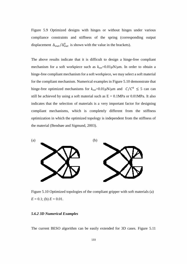
133
Figure 5.9 Optimized designs with hinges or without hinges under various
compliance constraints and stiffness of the spring (corresponding output
displacement ∆𝑜𝑢𝑡 ∆𝑜𝑢𝑡0⁄ is shown with the value in the brackets).
The above results indicate that it is difficult to design a hinge-free compliant
mechanism for a soft workpiece such as kout=0.01μN/μm. In order to obtain a
hinge-free compliant mechanism for a soft workpiece, we may select a soft material
for the compliant mechanism. Numerical examples in Figure 5.10 demonstrate that
hinge-free optimized mechanisms for kout=0.01μN/μm and 𝐶 𝐶0⁄ ≤ 5 can can
still be achieved by using a soft material such as E = 0.1MPa or 0.01MPa. It also
indicates that the selection of materials is a very important factor for designing
compliant mechanisms, which is completely different from the stiffness
optimization in which the optimized topology is independent from the stiffness of
the material (Bendsøe and Sigmund, 2003).
(a) (b)
Figure 5.10 Optimized topologies of the compliant gripper with soft materials
Figure 5.10 Optimized topologies of the compliant gripper with soft materials (a)
E = 0.1; (b) E = 0.01.
5.6.2 3D Numerical Examples
The current BESO algorithm can be easily extended for 3D cases. Figure 5.11
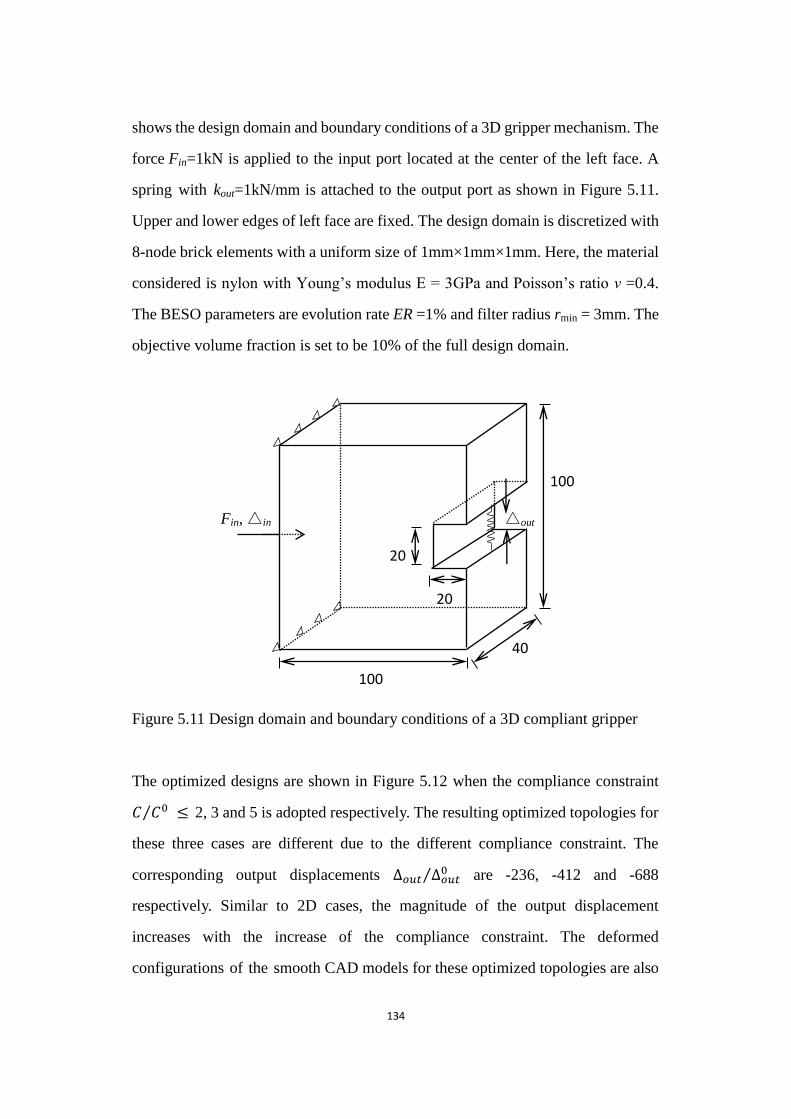
134
shows the design domain and boundary conditions of a 3D gripper mechanism. The
force Fin=1kN is applied to the input port located at the center of the left face. A
spring with kout=1kN/mm is attached to the output port as shown in Figure 5.11.
Upper and lower edges of left face are fixed. The design domain is discretized with
8-node brick elements with a uniform size of 1mm×1mm×1mm. Here, the material
considered is nylon with Young‟s modulus E = 3GPa and Poisson‟s ratio ν =0.4.
The BESO parameters are evolution rate ER =1% and filter radius rmin = 3mm. The
objective volume fraction is set to be 10% of the full design domain.
Figure 5.11 Design domain and boundary conditions of a 3D compliant gripper
Figure 5.11 Design domain and boundary conditions of a 3D compliant gripper
The optimized designs are shown in Figure 5.12 when the compliance constraint
𝐶 𝐶0⁄ ≤ 2, 3 and 5 is adopted respectively. The resulting optimized topologies for
these three cases are different due to the different compliance constraint. The
corresponding output displacements ∆𝑜𝑢𝑡 ∆𝑜𝑢𝑡0⁄ are -236, -412 and -688
respectively. Similar to 2D cases, the magnitude of the output displacement
increases with the increase of the compliance constraint. The deformed
configurations of the smooth CAD models for these optimized topologies are also
Fin, △in △out
20
100
20
40
100
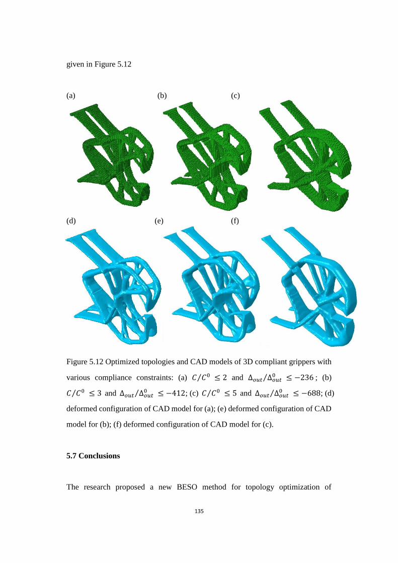
135
given in Figure 5.12
(a) (b) (c)
(d) (e) (f)
Figure 5.12 Optimized topologies and CAD models of 3D compliant grippers with various compliance constraints
Figure 5.12 Optimized topologies and CAD models of 3D compliant grippers with
various compliance constraints: (a) 𝐶 𝐶0⁄ ≤ 2 and ∆𝑜𝑢𝑡 ∆𝑜𝑢𝑡0⁄ ≤ −236 ; (b)
𝐶 𝐶0⁄ ≤ 3 and ∆𝑜𝑢𝑡 ∆𝑜𝑢𝑡0⁄ ≤ −412; (c) 𝐶 𝐶0⁄ ≤ 5 and ∆𝑜𝑢𝑡 ∆𝑜𝑢𝑡
0⁄ ≤ −688; (d)
deformed configuration of CAD model for (a); (e) deformed configuration of CAD
model for (b); (f) deformed configuration of CAD model for (c).
5.7 Conclusions
The research proposed a new BESO method for topology optimization of
136
compliant mechanisms by maximizing the flexibility subject to the mean
compliance and volume constraints. The compliance constraint is imposed on the
optimization algorithm by introducing a Lagrange multiplier. Based on the derived
sensitivity numbers, the discrete design variables are gradually updated until a
convergent solution is achieved.
Using the proposed BESO method, a set of optimized designs with and without
hinges has been obtained by altering the desired structural stiffness of compliant
mechanisms. The flexibility of the optimized compliant mechanism generally
increases with the compliance constraint, so that the resulting design has the
improved capacity of transferring the energy/motion from the input port to the
output port. However, such an optimized compliant mechanism may have low
stiffness to resist external forces and also contain hinge regions which are difficult
to manufacture especially for a micro system. To achieve a hinge-free compliant
mechanism, it is recommended that the flexibility of the compliant mechanism be
optimized by specifying a low compliance constraint or increasing the stiffness of
the workpiece. For an extreme soft workpiece, selecting a soft material for
compliant mechanisms can also preclude the formation of hinge regions during the
optimization process.
References
Ansola, R., Veguería, E., Canales, J. and Tárrago, J. A., 2007, "A simple evolutionary topology
optimization procedure for compliant mechanism design ", Finite Elements in Analysis and
Design 44(1-2), 53-62.
Bendsøe, M. P. and Sigmund, O., 2003. Topology Optimization: Theory, Method and Application,
Springer, Berlin.
Frecker, M. I., Ananthasuresh, G. K., Nishiwaka, S., Kikuchi, N. and Kota, S., 1997, "Topological

137
Synthesis of Compliant Mechanisms Using Multi-Criteria Optimization", Journal of
Mechanical Design 119(2), 238-245.
Huang, X. and Xie, Y. M., 2010. Evolutionary Topology Optimization of Continuum Structures :
Methods and Applications, John Wiley & Sons, Chichester.
Huang, X. and Xie, Y. M., 2010a, "Evolutionary topology optimization of continuum structures with
an additional displacement constraint", Structural and Multidisciplinary Optimization
40(16), 409-416.
Lau, G. K., Du, H. and Lim, M. K., 2001, "Use of functional specifications as objective functions in
topological optimization of compliant mechanism", Computer Methods in Applied
Mechanics and Engineering 190(34), 4421-4433.
Lin, J., Luo, Z. and Tong, L., 2010, "A new multi-objective programming scheme for topology
optimization of compliant mechanisms", Structural and Multidisciplinary Optimization
40(1-6), 241-255.
Rahmatalla, S. and Swan, C. C., 2005, "Sparse monolithic compliant mechanisms using continuum
structural topology optimization", International Journal for Numerical Methods in
Engineering 62(12), 1579-1605.
Yoon, G. H., Kim, Y. Y., Bendsøe, M. P. and Sigmund, O., 2004, "Hinge-free topology optimization
with embedded translation-invariant differentiable wavelet shrinkage", Structural and
Multidisciplinary Optimization 27(3), 139-150.
Zhu, B., Zhang, X. and Wang, N., 2013, "Topology optimization of hinge-free compliant
mechanisms with multiple outputs using level set method", Structural and
Multidisciplinary Optimization 47(5), 659-672.
138
Chapter 6
Evolutionary Topology Optimization
of Hinge-free Compliant Mechanisms
139
Chapter Overview
This chapter aims to develop a BESO method for the design of hinge-free
compliant mechanisms. A new objective function will be proposed to maximize
the desirable displacement and simultaneously preclude the formation of hinges.
Sensitivity numbers are derived according to the variation of the objective
function with respect to the design variables. Based on the resulting sensitivity
numbers, the BESO procedure is established by gradually removing and adding
elements until an optimal topology is achieved. Several 2D and 3D examples are
given to demonstrate the effectiveness of the proposed BESO method for the
design of various hinge-free compliant mechanisms.
6.1 Optimization Problem and Structural Analysis
The designs of compliant mechanisms using topology optimization techniques
naturally lead to the introduction of hinges into the models, making them function
essentially as rigid-body mechanisms (Rahmatalla and Swan, 2005). Such hinge
zones cause high stress concentration and are difficult to fabricate for micro-scale
systems.
Recently, several different techniques have been established and developed for
eliminating de facto hinges in the design of compliant mechanisms such as
embedding wavelet-base functions (Poulsen, 2002; Yoon et al., 2004), imposing a
minimum length constraint (Poulsen, 2003) and filter schemes (Sigmund, 2007).
Such morphology-based approaches could greatly reduce the occurrence of
one-node connected hinges, but were not entirely effective due to the nature of the
optimization problem. Reformulating the problem as a multi-criteria optimization
might be an effective way for entirely circumventing de facto hinge regions which
140
generally lie along the force path from the mechanism input port to the output port.
Therefore, this research develops a new BESO algorithm for optimally designing
hinge-free compliant mechanisms. The strain energy of the structure is introduced
into the formulation of the optimization problem. Based on the finite element
analysis and sensitivity analysis, a BESO procedure is established to evolve the
compliant mechanism to an optimum. Several examples are presented to
demonstrate the effectiveness of the proposed method for designing various
hinge-free compliant mechanisms. Different from other density-based topology
optimization methods, the traditional BESO can provide clear topological design of
compliant mechanisms without any „grey‟ areas.
Consider a general design domain Ω under given loading and boundary conditions,
which have been depicted in Figure 6.1a. It is assumed that the applied force at the
input port i is Fin and the reaction force at the output port j is Fout. The latter force is
acting on a workpiece which is modeled by a spring with a constant stiffness, kout.
The resulting input displacement is △in at the input port i and the output
displacement △out at the output port j. As mentioned, an efficient compliant
mechanism should be flexible enough to produce expected kinematic motion under
the action of applied loads to satisfy the flexibility requirement (Joo and Kota,
2004). Therefore, the design objective could be maximizing a displacement ratio,
which is called geometric advantage out inGA . Meanwhile, the compliant
mechanism becomes a structure as shown in Figure 6.1b when the output port is
fixed. Such a structure should possess a certain stiffness to limit the input
displacement at the input port. In other words, a compliant mechanism should be
flexible enough to produce the expected kinematic motion and stiff enough to resist
applied forces (Nishiwaki et al., 1998; Joo et al., 2000). The stiffness of the
structure can be inversely measured by the mean compliance or total strain energy
in the structure. Furthermore, maximizing the structural stiffness or minimizing the

141
total strain energy can also preclude the formation of hinges in the design of
compliant mechanism (Rahmatalla and Swan, 2005). Considering those factors, we
can mathematically formulate an optimization problem for the design of a
hinge-free compliant mechanism as follows
Maximize = 𝐺𝐴 𝑆𝐸⁄ (6.1)
Subject to: 𝑉∗ − ∑ 𝑉𝑒𝑁𝑒=1 𝑒 = 0
𝑒 = 𝑚𝑖𝑛 𝑜𝑟 1
where 𝑆𝐸 = 𝐮 𝐮 2⁄ is the total elastic strain energy in the continuum. The
structure has been shown in Figure 6.1b. A small value of 𝑚𝑖𝑛, e.g. 0.001, is used
to denote the soft elements.
(a) (b)
(c) (d)
Figure 6.1 A general design model for hinge-free compliant mechanism
Input Port i
Fin , △in
Output Port j
kout
Fout
Ω △out
Ω
F1, △11 △21
Ω
△12 F2, △22
Ω
142
Figure 6.1 A general design model for hinge-free compliant mechanism (a)
mechanism design; (b) structure design; (c) input load case; (d) output load case
The analysis of the compliant mechanism can be the superposition of two load
cases as shown in Figures 6.1c and d. The compliant mechanism is equivalent to the
linear combination of two structures when the displacement relationships are
satisfied in Equation 4.3. The forces should satisfy the relationship of Equation 4.4,
and the input and output displacements can be found in Equation 4.6. According to
the dummy load approach, displacements ∆𝑖𝑗 can be expressed as Equation 4.9,
in which 𝐮1 and 𝐮2 represent the displacement fields of two structures shown in
Figures 6.1c and 6.1d respectively. Similarly, the displacement field of the structure
in Figure 6.1b, u can be expressed by 𝐮1 and 𝐮2 as
𝐮 = 𝐮1 −∆11
∆12× 𝐮2 (6.2)
6.2 Sensitivity Number
The sensitivity of displacements ∆𝑖𝑗 can be found in Equation 4.15. The
sensitivity of the displacement can be expressed at elemental levels for solid and
soft elements, as two discrete design variables, 𝑒 = 1 (solid elements) and 𝑚𝑖𝑛
(soft elements), are employed in the soft-kill BESO (Huang and Xie, 2010).
∆𝑖
𝑥𝑒= {
−𝑝𝐮𝑗,𝑒 𝑒
0𝐮𝑖,𝑒 𝐹𝑖 𝑤𝑒𝑛 𝑒 = 1⁄
−𝑝 𝑚𝑖𝑛𝑝−1𝐮𝑗,𝑒
𝑒0𝐮𝑖,𝑒 𝐹𝑖 𝑤𝑒𝑛 𝑒 = 𝑚𝑖𝑛⁄
(6.3)
With the help of Equations 4.18 and 4.19, the sensitivity of the geometric
advantage can be obtained.
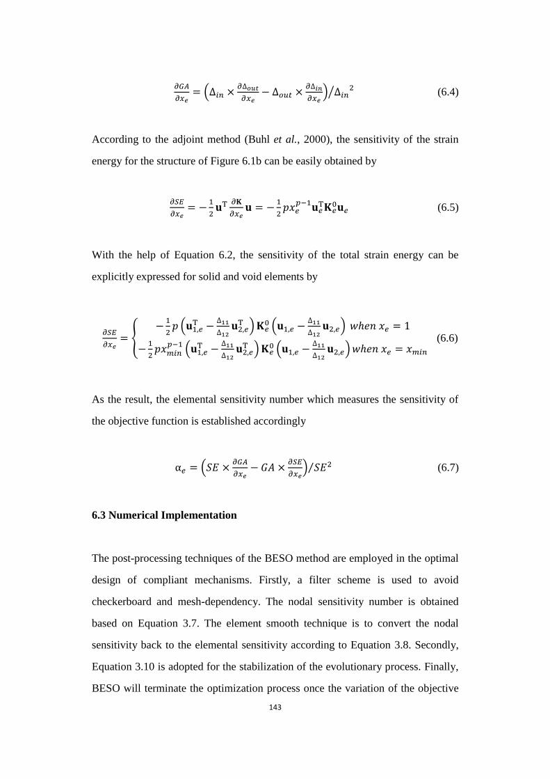
143
𝑥𝑒= (∆𝑖𝑛 ×
𝜕∆𝑜
𝜕𝑥𝑒− ∆𝑜𝑢𝑡 ×
𝜕∆𝑖𝑛
𝜕𝑥𝑒) ∆𝑖𝑛
2⁄ (6.4)
According to the adjoint method (Buhl et al., 2000), the sensitivity of the strain
energy for the structure of Figure 6.1b can be easily obtained by
𝑥𝑒= −
1
2𝐮
𝜕
𝜕𝑥𝑒𝐮 = −
1
2𝑝 𝑒
𝑝−1𝐮𝑒 𝑒
0𝐮𝑒 (6.5)
With the help of Equation 6.2, the sensitivity of the total strain energy can be
explicitly expressed for solid and void elements by
𝑥𝑒= {
−1
2𝑝 (𝐮1,𝑒
−∆11
∆12𝐮2,𝑒 ) 𝑒
0 (𝐮1,𝑒 −∆11
∆12𝐮2,𝑒) 𝑤𝑒𝑛 𝑒 = 1
−1
2𝑝 𝑚𝑖𝑛
𝑝−1 (𝐮1,𝑒 −
∆11
∆12𝐮2,𝑒 ) 𝑒
0 (𝐮1,𝑒 −∆11
∆12𝐮2,𝑒)𝑤𝑒𝑛 𝑒 = 𝑚𝑖𝑛
(6.6)
As the result, the elemental sensitivity number which measures the sensitivity of
the objective function is established accordingly
𝑒 = (𝑆𝐸 ×𝜕
𝜕𝑥𝑒− 𝐺𝐴 ×
𝜕
𝜕𝑥𝑒) 𝑆𝐸2⁄ (6.7)
6.3 Numerical Implementation
The post-processing techniques of the BESO method are employed in the optimal
design of compliant mechanisms. Firstly, a filter scheme is used to avoid
checkerboard and mesh-dependency. The nodal sensitivity number is obtained
based on Equation 3.7. The element smooth technique is to convert the nodal
sensitivity back to the elemental sensitivity according to Equation 3.8. Secondly,
Equation 3.10 is adopted for the stabilization of the evolutionary process. Finally,
BESO will terminate the optimization process once the variation of the objective
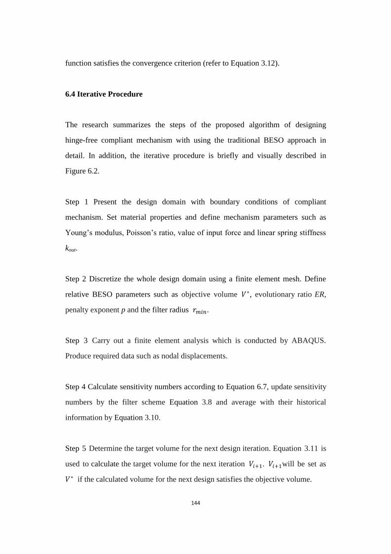
144
function satisfies the convergence criterion (refer to Equation 3.12).
6.4 Iterative Procedure
The research summarizes the steps of the proposed algorithm of designing
hinge-free compliant mechanism with using the traditional BESO approach in
detail. In addition, the iterative procedure is briefly and visually described in
Figure 6.2.
Step 1 Present the design domain with boundary conditions of compliant
mechanism. Set material properties and define mechanism parameters such as
Young‟s modulus, Poisson‟s ratio, value of input force and linear spring stiffness
kout.
Step 2 Discretize the whole design domain using a finite element mesh. Define
relative BESO parameters such as objective volume 𝑉∗, evolutionary ratio ER,
penalty exponent p and the filter radius 𝑟𝑚𝑖𝑛.
Step 3 Carry out a finite element analysis which is conducted by ABAQUS.
Produce required data such as nodal displacements.
Step 4 Calculate sensitivity numbers according to Equation 6.7, update sensitivity
numbers by the filter scheme Equation 3.8 and average with their historical
information by Equation 3.10.
Step 5 Determine the target volume for the next design iteration. Equation 3.11 is
used to calculate the target volume for the next iteration 𝑉𝑖+1. 𝑉𝑖+1will be set as
𝑉∗ if the calculated volume for the next design satisfies the objective volume.

145
Step 6 Rank all elements based on their sensitivity numbers in descending order
and set the threshold of the sensitivity number 𝛼𝑡ℎ so that the total volume of
elements with 𝛼𝑖 > 𝛼𝑡ℎ equals the target volume of the next iteration Vi+1.
Step 7 Reset the design variables of the design domain. That is, for solid elements,
the elemental density is switched from 1 to 𝑚𝑖𝑛 if 𝛼𝑖 ≤ 𝛼𝑡ℎ, and the element
density for soft elements will be changed from 𝑚𝑖𝑛 to 1 if 𝛼𝑖 > 𝛼𝑡ℎ.
Step 8 Repeat Steps 3-7 until both the volume fraction reaches target volume and
the performance of objective function satisfies its convergence criteria according to
Equation 3.12.
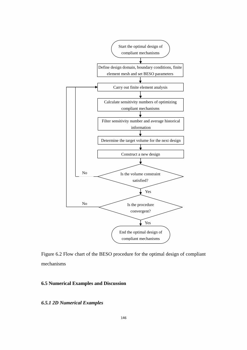
146
Figure 6.2 Flow chart of the BESO procedure for the optimal design of compliant mechanisms
Figure 6.2 Flow chart of the BESO procedure for the optimal design of compliant
mechanisms
6.5 Numerical Examples and Discussion
6.5.1 2D Numerical Examples
No
Yes
Yes
End the optimal design of
compliant mechanisms
Start the optimal design of
compliant mechanisms
Define design domain, boundary conditions, finite
element mesh and set BESO parameters
Carry out finite element analysis
Calculate sensitivity numbers of optimizing
compliant mechanisms
Filter sensitivity number and average historical
information
Determine the target volume for the next design
Construct a new design
Is the volume constraint
satisfied?
Is the procedure
convergent?
No
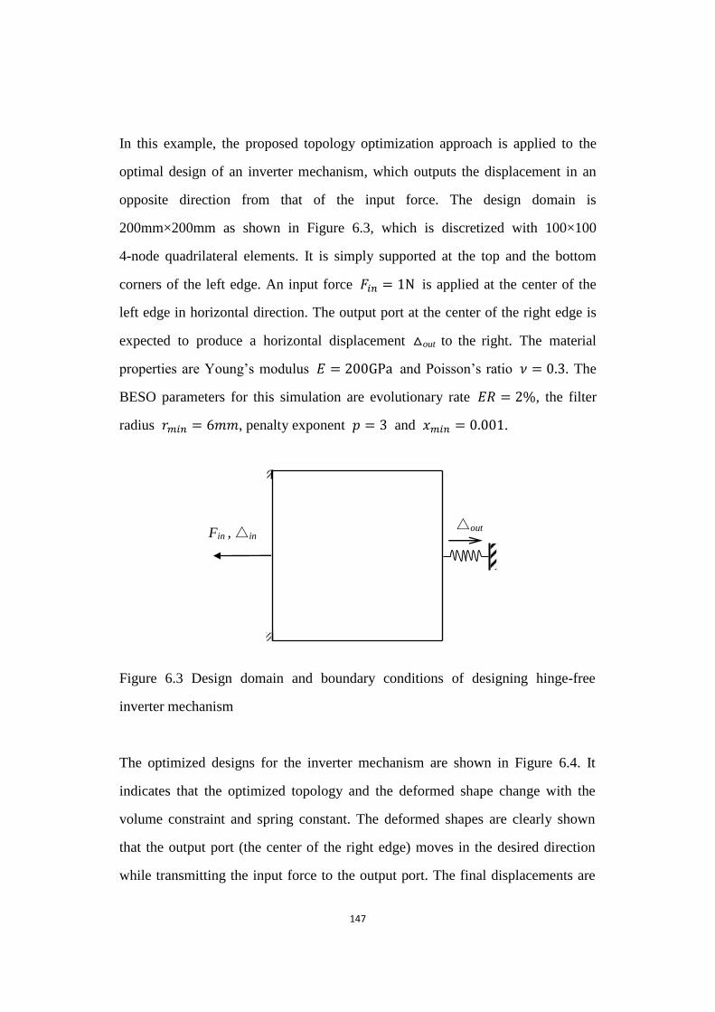
147
In this example, the proposed topology optimization approach is applied to the
optimal design of an inverter mechanism, which outputs the displacement in an
opposite direction from that of the input force. The design domain is
200mm×200mm as shown in Figure 6.3, which is discretized with 100×100
4-node quadrilateral elements. It is simply supported at the top and the bottom
corners of the left edge. An input force 𝐹𝑖𝑛 = 1 is applied at the center of the
left edge in horizontal direction. The output port at the center of the right edge is
expected to produce a horizontal displacement △out to the right. The material
properties are Young‟s modulus 𝐸 = 200 and Poisson‟s ratio = 0 3. The
BESO parameters for this simulation are evolutionary rate 𝐸𝑅 = 2 , the filter
radius 𝑟𝑚𝑖𝑛 = 6 , penalty exponent 𝑝 = 3 and 𝑚𝑖𝑛 = 0 001.
Figure 6.3 Design domain and boundary conditions of designing hinge-free inverter mechanism
Figure 6.3 Design domain and boundary conditions of designing hinge-free
inverter mechanism
The optimized designs for the inverter mechanism are shown in Figure 6.4. It
indicates that the optimized topology and the deformed shape change with the
volume constraint and spring constant. The deformed shapes are clearly shown
that the output port (the center of the right edge) moves in the desired direction
while transmitting the input force to the output port. The final displacements are
△out Fin , △in

148
respectively 1.14×10⁻²
mm, 5.07×10⁻²
mm, 1.09×10⁻²
mm and 4.78×10⁻²
mm. The
resulting hinge-free topologies are very similar to those obtained using the
density-based optimization approach (Sigmund, 1997) but without any “grey
area”. This example demonstrated that the proposed formulation is effective for
solving the problem of the design of compliant mechanisms.
(a)
(b)
(c)
(d)
Figure 6.4 Optimum topologies for the hinge-free inverter mechanism
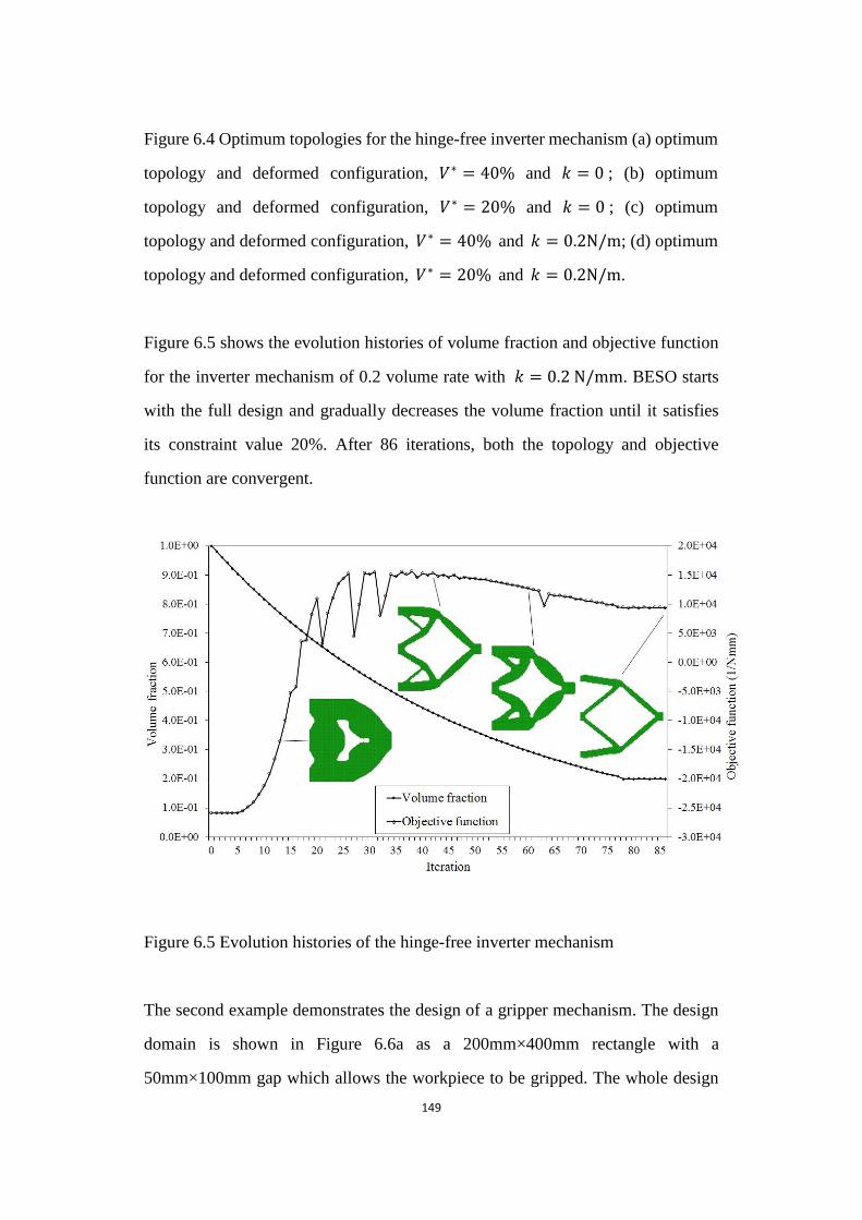
149
Figure 6.4 Optimum topologies for the hinge-free inverter mechanism (a) optimum
topology and deformed configuration, 𝑉∗ = 40 and 𝑘 = 0 ; (b) optimum
topology and deformed configuration, 𝑉∗ = 20 and 𝑘 = 0 ; (c) optimum
topology and deformed configuration, 𝑉∗ = 40 and 𝑘 = 0 2 / ; (d) optimum
topology and deformed configuration, 𝑉∗ = 20 and 𝑘 = 0 2 / .
Figure 6.5 shows the evolution histories of volume fraction and objective function
for the inverter mechanism of 0.2 volume rate with 𝑘 = 0 2 / . BESO starts
with the full design and gradually decreases the volume fraction until it satisfies
its constraint value 20%. After 86 iterations, both the topology and objective
function are convergent.
Figure 6.5 Evolution histories of the hinge-free inverter mechanism
Figure 6.5 Evolution histories of the hinge-free inverter mechanism
The second example demonstrates the design of a gripper mechanism. The design
domain is shown in Figure 6.6a as a 200mm×400mm rectangle with a
50mm×100mm gap which allows the workpiece to be gripped. The whole design
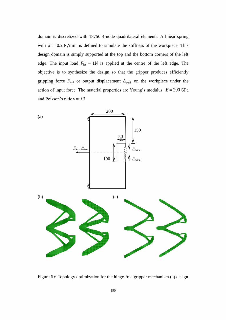
150
domain is discretized with 18750 4-node quadrilateral elements. A linear spring
with 𝑘 = 0 2 / is defined to simulate the stiffness of the workpiece. This
design domain is simply supported at the top and the bottom corners of the left
edge. The input load 𝐹𝑖𝑛 = 1 is applied at the centre of the left edge. The
objective is to synthesize the design so that the gripper produces efficiently
gripping force Fout or output displacement ∆𝑜𝑢𝑡 on the workpiece under the
action of input force. The material properties are Young‟s modulus 200E GPa
and Poisson‟s ratio 3.0v .
(a)
(b) (c)
Figure 6.6 Topology optimization for the hinge-free gripper mechanism
Figure 6.6 Topology optimization for the hinge-free gripper mechanism (a) design
200
△out
△out Fin, △in
100
50
150
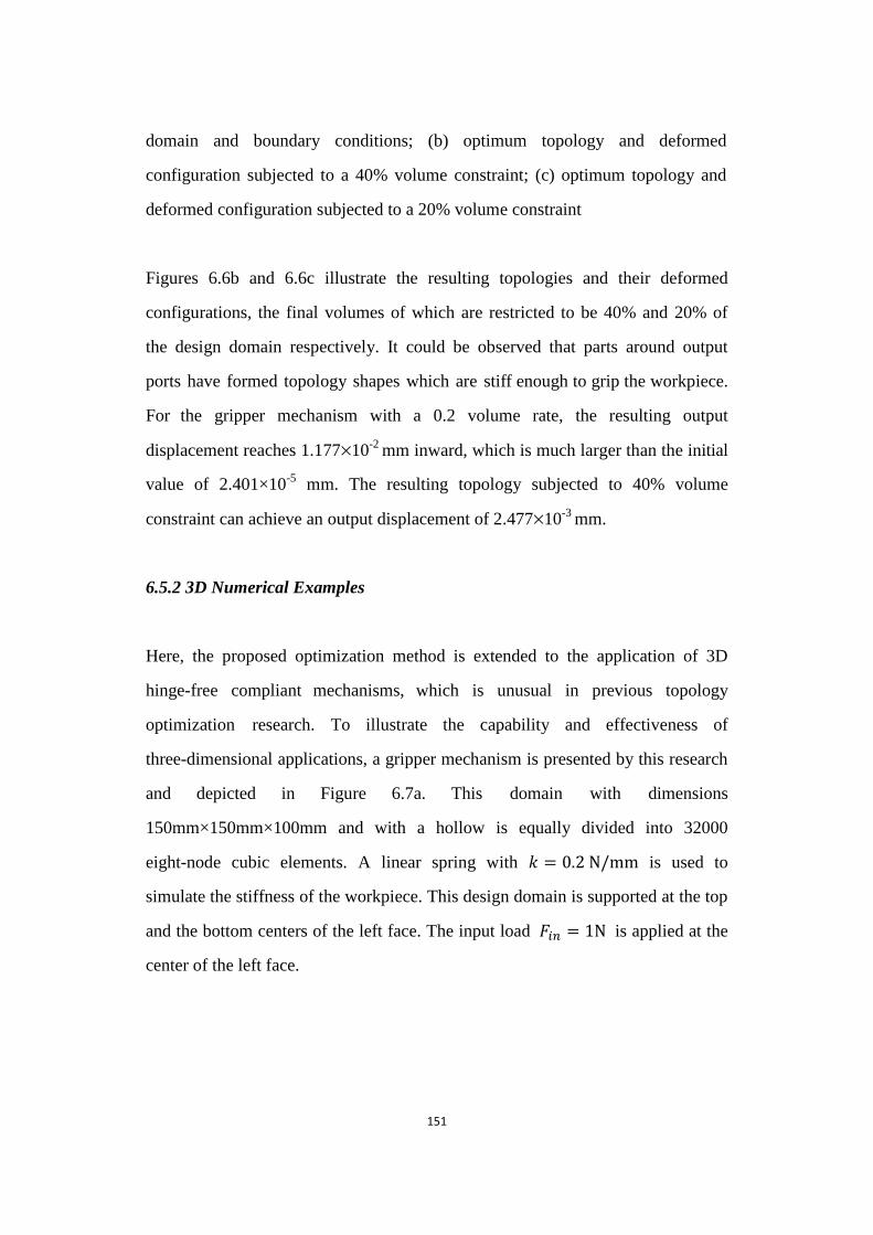
151
domain and boundary conditions; (b) optimum topology and deformed
configuration subjected to a 40% volume constraint; (c) optimum topology and
deformed configuration subjected to a 20% volume constraint
Figures 6.6b and 6.6c illustrate the resulting topologies and their deformed
configurations, the final volumes of which are restricted to be 40% and 20% of
the design domain respectively. It could be observed that parts around output
ports have formed topology shapes which are stiff enough to grip the workpiece.
For the gripper mechanism with a 0.2 volume rate, the resulting output
displacement reaches 1.177×10⁻²
mm inward, which is much larger than the initial
value of 2.401×10⁻⁵
mm. The resulting topology subjected to 40% volume
constraint can achieve an output displacement of 2.477×10⁻³
mm.
6.5.2 3D Numerical Examples
Here, the proposed optimization method is extended to the application of 3D
hinge-free compliant mechanisms, which is unusual in previous topology
optimization research. To illustrate the capability and effectiveness of
three-dimensional applications, a gripper mechanism is presented by this research
and depicted in Figure 6.7a. This domain with dimensions
150mm×150mm×100mm and with a hollow is equally divided into 32000
eight-node cubic elements. A linear spring with 𝑘 = 0 2 / is used to
simulate the stiffness of the workpiece. This design domain is supported at the top
and the bottom centers of the left face. The input load 𝐹𝑖𝑛 = 1 is applied at the
center of the left face.

152
(a)
(b) (c)
Figure 6.7 Topology optimization for the 3D hinge-free gripper mechanism
Figure 6.7 Topology optimization for the 3D hinge-free gripper mechanism (a)
Design domain and boundary conditions; (b) FE optimized topology; (c) Deformed
configuration of the CAD model.
The objective is to obtain the gripper efficiently produce a gripping force Fout or
output displacement ∆𝑜𝑢𝑡. The material properties are a Young‟s modulus of
150
100
100
50
50
△out
△out
Fin, △in
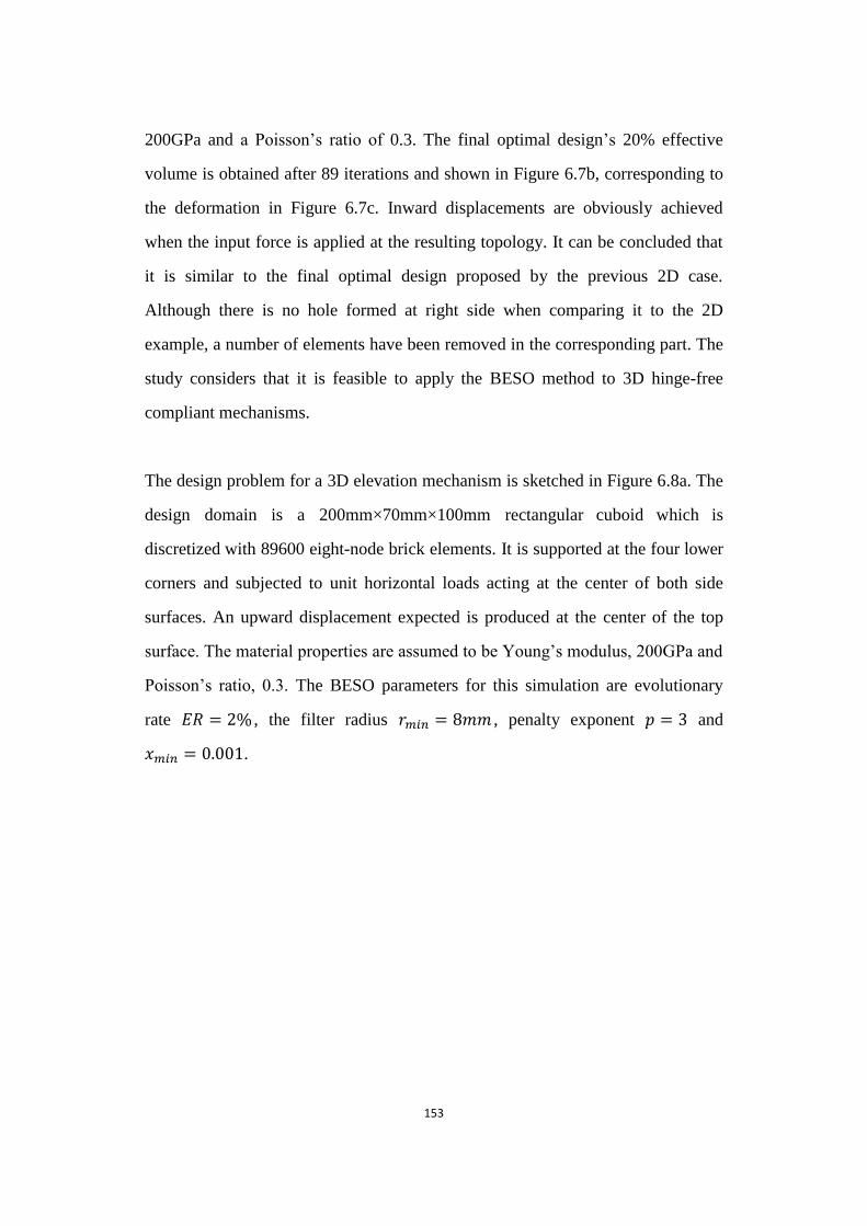
153
200GPa and a Poisson‟s ratio of 0.3. The final optimal design‟s 20% effective
volume is obtained after 89 iterations and shown in Figure 6.7b, corresponding to
the deformation in Figure 6.7c. Inward displacements are obviously achieved
when the input force is applied at the resulting topology. It can be concluded that
it is similar to the final optimal design proposed by the previous 2D case.
Although there is no hole formed at right side when comparing it to the 2D
example, a number of elements have been removed in the corresponding part. The
study considers that it is feasible to apply the BESO method to 3D hinge-free
compliant mechanisms.
The design problem for a 3D elevation mechanism is sketched in Figure 6.8a. The
design domain is a 200mm×70mm×100mm rectangular cuboid which is
discretized with 89600 eight-node brick elements. It is supported at the four lower
corners and subjected to unit horizontal loads acting at the center of both side
surfaces. An upward displacement expected is produced at the center of the top
surface. The material properties are assumed to be Young‟s modulus, 200GPa and
Poisson‟s ratio, 0.3. The BESO parameters for this simulation are evolutionary
rate 𝐸𝑅 = 2 , the filter radius 𝑟𝑚𝑖𝑛 = 8 , penalty exponent 𝑝 = 3 and
𝑚𝑖𝑛 = 0 001.
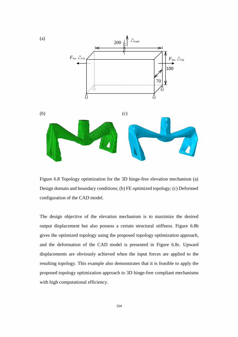
154
(a)
(b) (c)
Figure 6.8 Topology optimization for the 3D hinge-free elevation mechanism
Figure 6.8 Topology optimization for the 3D hinge-free elevation mechanism (a)
Design domain and boundary conditions; (b) FE optimized topology; (c) Deformed
configuration of the CAD model.
The design objective of the elevation mechanism is to maximize the desired
output displacement but also possess a certain structural stiffness. Figure 6.8b
gives the optimized topology using the proposed topology optimization approach,
and the deformation of the CAD model is presented in Figure 6.8c. Upward
displacements are obviously achieved when the input forces are applied to the
resulting topology. This example also demonstrates that it is feasible to apply the
proposed topology optimization approach to 3D hinge-free compliant mechanisms
with high computational efficiency.
70
Fin, △in
200
Fin, △in
100
△out

155
Finally, this research analyses the design problem for a 3D contraction
mechanism. The design domain is shown in Figure 6.9a and equally divided into
76032 eight-node cubic elements. The mechanism is supported at the four lower
corners and is subjected to a vertical input load Fin=1N acting at the center of the
bottom face. Four corners situated at the top face of the 90mm×90mm×45mm
groove are expected to produce a contraction inwards when a unit input force is
applying at the structure. Iterative process reaches the allowable volume, namely
10% for solid elements, after 118 iterations. The final optimal topology and the
deformation of the CAD model for the contraction mechanism are presented in
Figures 6.9b and 6.9c. It can be seen that the desired displacements are obtained
through the elastic deformation of the mechanism which is composed of clear
members without any hinges.
(a)
(b) (c)
Figure 6.9 Topology optimization for the 3D hinge-free contraction mechanism
180
180
135
Fin, △in
△out
156
Figure 6.9 Topology optimization for the 3D hinge-free contraction mechanism (a)
Design domain and boundary conditions; (b) FE optimized topology; (c) Deformed
configuration of the CAD model
6.6 Conclusions
This research proposed a BESO procedure for the design of 2D and 3D hinge-free
compliant mechanisms. The optimization problem is formulated as maximizing
the geometry advantage and structural stiffness of the compliant mechanisms
simultaneously. The sensitivity analysis is conducted by applying the adjoint
method to both the kinematical function and the structural function and then the
BESO procedure is adopted based on the resulting sensitivity numbers. Through
gradually removing and adding material, the optimized topology of compliant
mechanisms is achieved for the defined design. The formation of hinges has been
successfully precluded due to the introduction of the strain energy into the
objective function. Numerical results show that desirable output displacements are
obtained through the elastic deformation of the mechanism designs and
demonstrate the effectiveness of the proposed BESO algorithm for the design of
various 2D and 3D hinge-free compliant mechanisms. Compared with other
density-based optimization methods, the current BESO algorithm provides clear
solid-void topologies of compliant mechanisms without any “grey” areas.
Overall, based on BESO methods, new formulations proposed in this dissertation
greatly promote topology optimization of linear compliant mechanisms. However,
it should be pointed out that the mentioned methods are limited in the framework of
linearized elasticity analysis. A nonlinear analysis is necessary in real applications
due to practical accuracy. Certainly, some concepts presented in the linear analysis
can be extended to the design of compliant mechanisms with large-displacement

157
behavior. Therefore, the next chapters will present the related nonlinear finite
element analysis and topology synthesis of large-displacement compliant
mechanisms.
References
Buhl, T., Pedersen, C. B. W. and Sigmund, O., 2000, "Stiffness design of geometrically nonlinear
structures using topology optimization", Structural and Multidisciplinary Optimization
19(2), 93-104.
Huang, X. and Xie, Y. M., 2010. Evolutionary Topology Optimization of Continuum Structures :
Methods and Applications, John Wiley & Sons, Chichester.
Joo, J. and Kota, S., 2004, "Topological synthesis of compliant mechanisms using nonlinear beam
elements", Mechanics Based Design of Structures and Machines 39(1), 17-38.
Joo, J., Kota, S. and Kikuchi, N., 2000, "Topological synthesis of compliant mechanisms using
linear beam elements", Mechanics of Structures and Machines 28(4), 245-280.
Nishiwaki, S., Frecker, M. I., Min, S. and Kikuchi, N., 1998, "Topology optimisation of compliant
mechanisms using the homogenization method", International Journal for Numerical
Methods in Engineering 42(3), 535-559.
Poulsen, T. A., 2002, "Topology optimization in wavelet space", International Journal for
Numerical Methods in Engineering 53(3), 567-582.
Poulsen, T. A., 2003, "A new scheme for imposing a minimum length scale in topology
optimization", International Journal for Numerical Methods in Engineering 57(6),
741-760.
Rahmatalla, S. and Swan, C. C., 2005, "Sparse monolithic compliant mechanisms using continuum
structural topology optimization", International Journal for Numerical Methods in
Engineering 62(12), 1579-1605.
Sigmund, O., 1997, "On the design of compliant mechanisms using topology optimization",
Mechanics of Structures and Machines 25(4), 493-524.

158
Sigmund, O., 2007, "Morphology-based black and white filters for topology optimization",
Structural and Multidisciplinary Optimization 33(4-5), 401-424.
Yoon, G. H., Kim, Y. Y., Bendsøe, M. P. and Sigmund, O., 2004, "Hinge-free topology optimization
with embedded translation-invariant differentiable wavelet shrinkage", Structural and
Multidisciplinary Optimization 27(3), 139-150.
159
Chapter 7
Topology Design of Nonlinear
Compliant Mechanisms
160
Chapter Overview
This dissertation has proposed several approaches for the systematic design field of
linear compliant mechanisms, demonstrating the capability and validity of the
improved algorithms. However, the optimal design of nonlinear compliant
mechanisms is necessary in real applications as the simulation is more accurate.
In this chapter, the research focuses on optimizing compliant mechanisms with
large-deformation behavior by extending related concepts from linear compliant
mechanism designs of Chapter 5.
7.1 Differences between Structural Linearity and Nonlinearity
Sometimes, the solutions to engineering problems are based on linear
approximations. Linear approximations can be considered and used to represent the
nonlinear structural analysis in many cases. For example, the structure produces a
small deformation, which can be neglected in equilibrium. The strain is
proportional to the stress. Forces are conservative and independent on
displacements in structural analysis. Structural supports remain unchanged when
loading. However, there are marked differences between linear and nonlinear
analysis as described in Table 7.1.
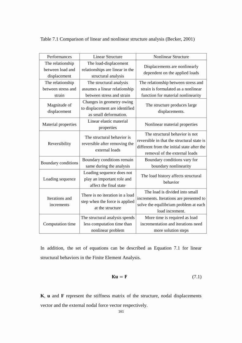
161
Table 7.1 Comparison of linear and nonlinear structure analysis (Becker, 2001)
Performances Linear Structure Nonlinear Structure
The relationship
between load and
displacement
The load-displacement
relationships are linear in the
structural analysis
Displacements are nonlinearly
dependent on the applied loads
The relationship
between stress and
strain
The structural analysis
assumes a linear relationship
between stress and strain
The relationship between stress and
strain is formulated as a nonlinear
function for material nonlinearity
Magnitude of
displacement
Changes in geometry owing
to displacement are identified
as small deformation.
The structure produces large
displacements.
Material properties Linear elastic material
properties Nonlinear material properties
Reversibility
The structural behavior is
reversible after removing the
external loads
The structural behavior is not
reversible in that the structural state is
different from the initial state after the
removal of the external loads
Boundary conditions Boundary conditions remain
same during the analysis
Boundary conditions vary for
boundary nonlinearity
Loading sequence
Loading sequence does not
play an important role and
affect the final state
The load history affects structural
behavior
Iterations and
increments
There is no iteration in a load
step when the force is applied
at the structure
The load is divided into small
increments. Iterations are presented to
solve the equilibrium problem at each
load increment.
Computation time
The structural analysis spends
less computation time than
nonlinear problem
More time is required as load
incrementation and iterations need
more solution steps
In addition, the set of equations can be described as Equation 7.1 for linear
structural behaviors in the Finite Element Analysis.
𝐮 = (7.1)
K, u and F represent the stiffness matrix of the structure, nodal displacements
vector and the external nodal force vector respectively.
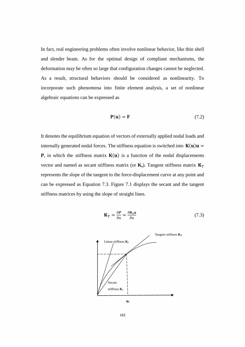
162
In fact, real engineering problems often involve nonlinear behavior, like thin shell
and slender beam. As for the optimal design of compliant mechanisms, the
deformation may be often so large that configuration changes cannot be neglected.
As a result, structural behaviors should be considered as nonlinearity. To
incorporate such phenomena into finite element analysis, a set of nonlinear
algebraic equations can be expressed as
(𝐮) = (7.2)
It denotes the equilibrium equation of vectors of externally applied nodal loads and
internally generated nodal forces. The stiffness equation is switched into (𝐮)𝐮 =
, in which the stiffness matrix (𝐮) is a function of the nodal displacements
vector and named as secant stiffness matrix (or Ks). Tangent stiffness matrix
represents the slope of the tangent to the force-displacement curve at any point and
can be expressed as Equation 7.3. Figure 7.1 displays the secant and the tangent
stiffness matrices by using the slope of straight lines.
=𝜕
𝜕𝑢=𝜕 𝐮
𝜕𝑢 (7.3)
Figure 7.1 Tangent and secant stiffness u0
Linear stiffness KL
Secant
stiffness Ks
Tangent stiffness KT

163
Figure 7.1 Tangent and secant stiffness
7.2 Types of Structural Nonlinearity
Nonlinear behaviors can be grouped into three main behaviors, namely boundary
nonlinearity, material nonlinearity and geometrical nonlinearity. One of them,
boundary nonlinearity involves in the change of the status in the structural analysis.
Deformation is not independent on external boundary conditions when loading. In
other words, component contacts produce stresses and friction, resulting in
disproportionate changes in deformation.
In addition, material nonlinearity exhibits nonlinear stress-strain relationship.
Possible material models include nonlinear elastic, elastoplastic, viscoelastic and
viscoplastic (Bhashyam, 2002). It is different with linear elasticity as the material is
no longer constant. For nonlinear elastic behavior regarding with materials, a
general equation can be formulated as 𝜎 = 𝐸 ( ) , in which the terms of the secant
modulus is used to define the relationship between stress and strains.
Geometrical nonlinearity is based on the nonlinearity in kinematic quantities like
the relationship of strain and displacement in solids. Large displacements, large
strains and large rotations are main reasons causing nonlinearities. For small
displacement analysis, the change in element stiffness contributing to the overall
structural stiffness can be ignored because of the very small deformation of the
element and change in its spatial orientation. On the other hand, the change in the
element geometrical shape, e.g. length and area, can lead to the change in the local
element stiffness in geometrically nonlinear structures (Wriggers, 2009). For
topology optimization of compliant mechanisms, previous research reviewed in
Chapter 2 has also addressed related geometrically nonlinear behaviors in

164
structural analysis.
7.3 Geometrical Nonlinearity in Designing Compliant Mechanisms
Designing compliant mechanisms has been facing many challenges. One of them
is to address geometrically nonlinear analysis (Zhaokun and Xianmin, 2006).
However, previous optimization designs of compliant mechanism are derived
mainly from linear finite element model based on the assumption that the structures
can only undergo small deformation. In fact, the optimal design of compliant
mechanisms using the linear analysis is not very accurate, and the optimal design of
compliant mechanisms with geometrically nonlinear behaviors is essential to
capture the large-displacement behavior in real applications. This is because the
nonlinearities are associated with the deformation of the constituting members in
the optimal design of compliant mechanisms. Compliant mechanisms generate
force and motion transmission through elastic deformation, in particular via large
deformation. Certainly, various objective functions of designing linear compliant
mechanisms are not suitable for nonlinear compliant mechanisms, and the
nonlinear finite element analysis may experience convergence difficulty (Luo and
Tong, 2008). Consequently, there is relatively little research focusing on topology
design of large-displacement compliant mechanisms using geometrically nonlinear
finite element models (Jinqing and Xianmin, 2011).
In this dissertation, the research will investigate the topology optimization of
compliant mechanisms undergoing a large deflection based on the modified BESO
method. A total Lagrange finite element formulation will be employed for the
geometrically nonlinear structural response (Buhl et al., 2000; Gea and Luo, 2001).
7.4 Optimization Problem and Structural Analysis
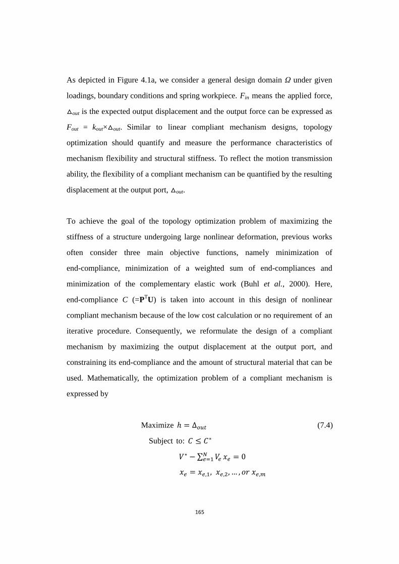
165
As depicted in Figure 4.1a, we consider a general design domain Ω under given
loadings, boundary conditions and spring workpiece. Fin means the applied force,
△out is the expected output displacement and the output force can be expressed as
Fout = kout×△out. Similar to linear compliant mechanism designs, topology
optimization should quantify and measure the performance characteristics of
mechanism flexibility and structural stiffness. To reflect the motion transmission
ability, the flexibility of a compliant mechanism can be quantified by the resulting
displacement at the output port, △out.
To achieve the goal of the topology optimization problem of maximizing the
stiffness of a structure undergoing large nonlinear deformation, previous works
often consider three main objective functions, namely minimization of
end-compliance, minimization of a weighted sum of end-compliances and
minimization of the complementary elastic work (Buhl et al., 2000). Here,
end-compliance C (=PTU) is taken into account in this design of nonlinear
compliant mechanism because of the low cost calculation or no requirement of an
iterative procedure. Consequently, we reformulate the design of a compliant
mechanism by maximizing the output displacement at the output port, and
constraining its end-compliance and the amount of structural material that can be
used. Mathematically, the optimization problem of a compliant mechanism is
expressed by
Maximize = ∆𝑜𝑢𝑡 (7.4)
Subject to: 𝐶 ≤ 𝐶∗
𝑉∗ − ∑ 𝑉𝑒𝑁𝑒=1 𝑒 = 0
𝑒 = 𝑒,1, 𝑒,2, … , 𝑜𝑟 𝑒,𝑚
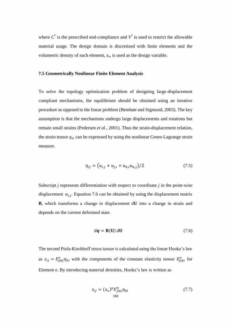
166
where C* is the prescribed end-compliance and V
* is used to restrict the allowable
material usage. The design domain is discretized with finite elements and the
volumetric density of each element, xe, is used as the design variable.
7.5 Geometrically Nonlinear Finite Element Analysis
To solve the topology optimization problem of designing large-displacement
compliant mechanisms, the equilibrium should be obtained using an iterative
procedure as opposed to the linear problem (Bendsøe and Sigmund, 2003). The key
assumption is that the mechanisms undergo large displacements and rotations but
remain small strains (Pedersen et al., 2001). Thus the strain-displacement relation,
the strain tensor ηij, can be expressed by using the nonlinear Green-Lagrange strain
measure.
𝑖𝑗 = (𝑢𝑖,𝑗 + 𝑢𝑗,𝑖 + 𝑢𝑘,𝑖𝑢𝑘,𝑗) 2⁄ (7.5)
Subscript j represents differentiation with respect to coordinate j in the point-wise
displacement 𝑢𝑖,𝑗. Equation 7.6 can be obtained by using the displacement matrix
B, which transforms a change in displacement dU into a change in strain and
depends on the current deformed state.
= ( ) (7.6)
The second Piola-Kirchhoff stress tensor is calculated using the linear Hooke‟s law
as 𝑠𝑖𝑗 = 𝐸𝑗𝑖𝑘𝑙𝑒 𝑘𝑙 with the components of the constant elasticity tensor 𝐸𝑗𝑖𝑘𝑙
𝑒 for
Element e. By introducing material densities, Hooke‟s law is written as
𝑠𝑖𝑗 = ( 𝑒)𝑝𝐸𝑗𝑖𝑘𝑙
0 𝑘𝑙 (7.7)
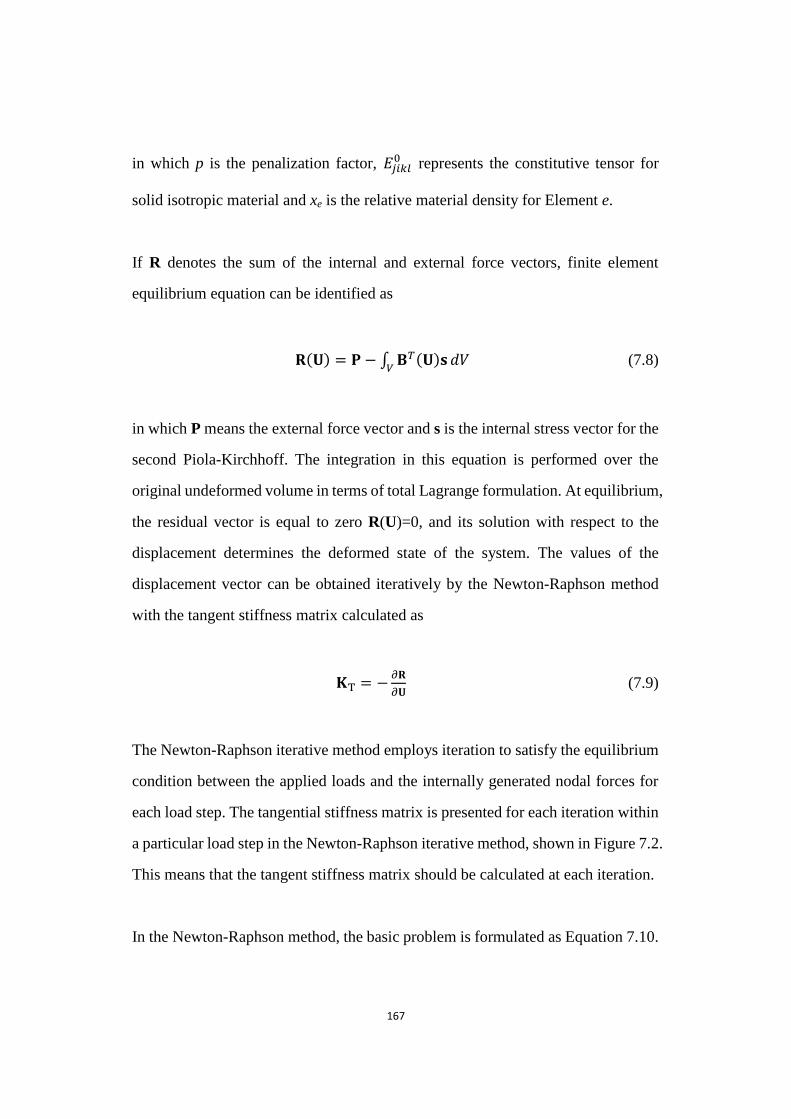
167
in which p is the penalization factor, 𝐸𝑗𝑖𝑘𝑙0 represents the constitutive tensor for
solid isotropic material and xe is the relative material density for Element e.
If R denotes the sum of the internal and external force vectors, finite element
equilibrium equation can be identified as
( ) = − ∫ 𝑇( ) 𝑑𝑉
(7.8)
in which P means the external force vector and s is the internal stress vector for the
second Piola-Kirchhoff. The integration in this equation is performed over the
original undeformed volume in terms of total Lagrange formulation. At equilibrium,
the residual vector is equal to zero R(U)=0, and its solution with respect to the
displacement determines the deformed state of the system. The values of the
displacement vector can be obtained iteratively by the Newton-Raphson method
with the tangent stiffness matrix calculated as
= −𝜕
𝜕 (7.9)
The Newton-Raphson iterative method employs iteration to satisfy the equilibrium
condition between the applied loads and the internally generated nodal forces for
each load step. The tangential stiffness matrix is presented for each iteration within
a particular load step in the Newton-Raphson iterative method, shown in Figure 7.2.
This means that the tangent stiffness matrix should be calculated at each iteration.
In the Newton-Raphson method, the basic problem is formulated as Equation 7.10.

168
∆𝐮1 ∆𝐮2
∆𝐮3
𝐅1
𝐅1𝑡+∆𝑡
𝐅2𝑡+∆𝑡
𝐅3𝑡+∆𝑡
𝐅𝑡+∆𝑡
𝐊0𝑡+∆𝑡
𝐊1𝑡+∆𝑡
𝐊1𝑡+∆𝑡
1st iteration 2nd iteration
𝑖−1𝑡+∆𝑡∆𝐮𝑖 =
𝑡+∆𝑡 − 𝑖−1𝑡+∆𝑡 (7.10)
𝑡+∆𝑡 is the vector of externally applied nodal loads. 𝑖−1𝑡+∆𝑡 indicates the vector of
generated nodal forces at the ith iteration. 𝑖−1𝑡+∆𝑡 points out the tangent stiffness
matrix at the beginning of the ith iteration. ∆𝐮𝑖 represents the vector of
incremental nodal displacement during the ith iteration. It is used to obtain the next
displacement approximation by 𝐮𝑖𝑡+∆𝑡 = 𝐮𝑖−1
𝑡+∆𝑡 + ∆𝐮𝑖 (Khosravi, 2007). This
iterative procedure will be repeated until the displacement increment ∆𝐮𝑖 or the
out-of-balance load vector ∆ 𝑖−1 is small enough.
Figure 7.2 Newton-Raphson iterative method
Figure 7.2 Newton-Raphson iterative method (Becker, 2001)
7.6 Sensitivity Number
In this dissertation, we derive the design sensitivities for compliant mechanisms
undergoing displacement through the adjoint method. The displacement ui of a
𝐏𝑡+∆𝑡
𝐏𝑡
𝐮0𝑡+∆𝑡 = 𝐮𝑡
𝐮1𝑡+∆𝑡 𝐮2
𝑡+∆𝑡 𝐮3𝑡+∆𝑡
𝐮𝑡+∆𝑡
Load
Displacement

169
specified degree of freedom i can be expressed as
𝑢𝑖 = (7.11)
in which L represents a unit load vector. Its value is equal to one at Position i,
namely Li=1, and values are zero for other positions. U means the displacement
vector generated by the load vector F applied at the input port.
The sensitivity of the displacement ui with respect to a change in design variable
can be expressed as Equation 7.12 assuming design-independent loads.
𝑑𝑢𝑖
𝑑𝑥𝑒=
𝑑
𝑑𝑥𝑒 (7.12)
The sensitivity analysis employs the adjoint method to determine 𝑑 𝑑 𝑒⁄ .
By introducing a vector of Lagrange multiplier λ, the previous displacement
function is augmented as a new function without changing anything by the term
, which is equal to zero and related to the residual term R defined in Equation
7.8.
𝑢𝑖 = + (7.13)
And the design sensitivity of the augmented function can be written as
𝑑𝑢𝑖
𝑑𝑥𝑒=
𝑑
𝑑𝑥𝑒+ (
𝜕
𝜕
𝑑
𝑑𝑥𝑒+
𝜕
𝜕𝑥𝑒) (7.14)
where 𝜕
𝜕 is equal to a negative tangent stiffness matrix KT according to the
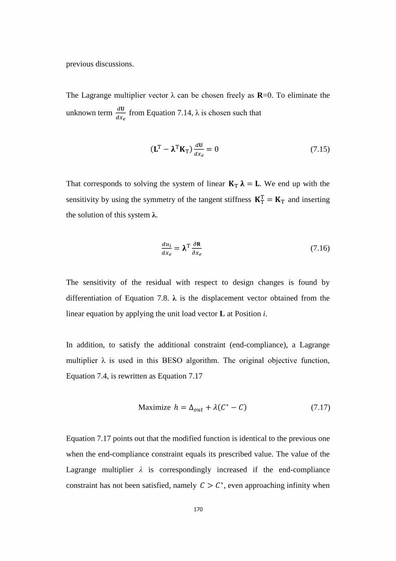
170
previous discussions.
The Lagrange multiplier vector λ can be chosen freely as R=0. To eliminate the
unknown term 𝑑
𝑑𝑥𝑒 from Equation 7.14, λ is chosen such that
( − )𝑑
𝑑𝑥𝑒= 0 (7.15)
That corresponds to solving the system of linear = . We end up with the
sensitivity by using the symmetry of the tangent stiffness = and inserting
the solution of this system λ.
𝑑𝑢𝑖
𝑑𝑥𝑒=
𝜕
𝜕𝑥𝑒 (7.16)
The sensitivity of the residual with respect to design changes is found by
differentiation of Equation 7.8. λ is the displacement vector obtained from the
linear equation by applying the unit load vector L at Position i.
In addition, to satisfy the additional constraint (end-compliance), a Lagrange
multiplier λ is used in this BESO algorithm. The original objective function,
Equation 7.4, is rewritten as Equation 7.17
Maximize = ∆𝑜𝑢𝑡 + (𝐶∗ − 𝐶) (7.17)
Equation 7.17 points out that the modified function is identical to the previous one
when the end-compliance constraint equals its prescribed value. The value of the
Lagrange multiplier λ is correspondingly increased if the end-compliance
constraint has not been satisfied, namely 𝐶 > 𝐶∗, even approaching infinity when
171
𝐶 is far greater than its prescribed value. That means we should minimize the
end-compliance to satisfy the constraint in later iterations. The Lagrange multiplier
λ will be equal to zero when the end-compliance constraint has already been
satisfied, 𝐶 < 𝐶∗. Equation 7.17 can be seen as an unconstraint objective function
in such a situation. The procedure of determining λ will be briefly presented in the
next section.
Therefore, the sensitivity number of the modified objective function can be
established in Equation 7.18 through the adjoint method, in which derivatives of
displacements are solved by using Equation 7.16.
𝛼𝑒 =𝑑ℎ
𝑑𝑥𝑒= ∆𝑜
𝑥𝑒−
𝑑𝐶
𝑑𝑥𝑒= ∆𝑜
𝑥𝑒− (
𝑖𝑛
2
∆𝑖𝑛
𝑥𝑒− 𝑘 ∆𝑜𝑢𝑡
∆𝑜
𝑥𝑒) (7.18)
7.7 Determination of Lagrange Multiplier
Similar to Section 5.3, in order to determine it, the Lagrange multiplier λ can be
defined as = (1 − 𝜔) 𝜔⁄ , in which 𝜔 ranges from a small value, like 0, to 1. In
other words, initial bound values of ω can be set as 𝜔𝑙𝑜𝑤𝑒𝑟 = 𝜔𝑚𝑖𝑛 and 𝜔𝑢𝑝𝑝𝑒𝑟 =
1 to implement the program. The volume constraint is firstly satisfied in the
constraint algorithm. The relative ranking of the sensitivity number is sorted based
on Equation 7.18. The volume constraint is achieved by gradually updating
elemental densities. To satisfy the end-compliance constraint in the algorithm, it is
necessary to estimate the variation of the end-compliance due to the variation of
design variables. Based on the value of the end-compliance in the current iteration
Ck, the end-compliance in the next iteration can be approximately estimated by
𝐶𝑘+1 𝐶𝑘 + ∑𝜕𝐶
𝜕𝑥𝑒× ∆ 𝑒𝑒 (∆xe = 0.02 in this chapter). Then, the value of ω can
be determined by using the bisection method in such a way that the end-compliance
constraint will be satisfied in the subsequent iterations.
172
7.8 Numerical Implementation
In the algorithm of designing compliant mechanisms with geometrically nonlinear
behaviors, the research employs post-processing techniques, which are the same as
those in the linear compliant mechanism design. Equation 3.9 is considered as a
filter scheme to avoid checkerboard and mesh-dependency. The elemental
sensitivity number is tackled by averaging sensitivity numbers from neighboring
elements. Then Equation 3.10 is adopted for the stabilization of the evolutionary
process. The evolution process will complete the whole optimization design once
the performance of the objective function satisfies the convergence criterion (refer
to Equation 3.12) and material volume reaches its objective volume.
7.9 Iterative Procedure
The procedure of optimizing geometrical nonlinear compliant mechanisms with
the structural flexibility constraint based on the BESO method is presented in the
following steps by summarizing the previous sections. Figure 7.3 aims to describe
briefly and visually its iterative procedure.
Step 1 Present the design domain with boundary conditions for optimizing
geometrically nonlinear compliant mechanism. Set material properties and
mechanism parameters such as Young‟s modulus E0 and Poisson‟s ratio.
Step 2 Discretize the whole design domain using a finite element mesh. Define
relative BESO parameters objective volume 𝑉∗, evolutionary ratio ER, penalty
exponent p and the filter radius 𝑟𝑚𝑖𝑛. Set the end-compliance constraint 𝐶∗.
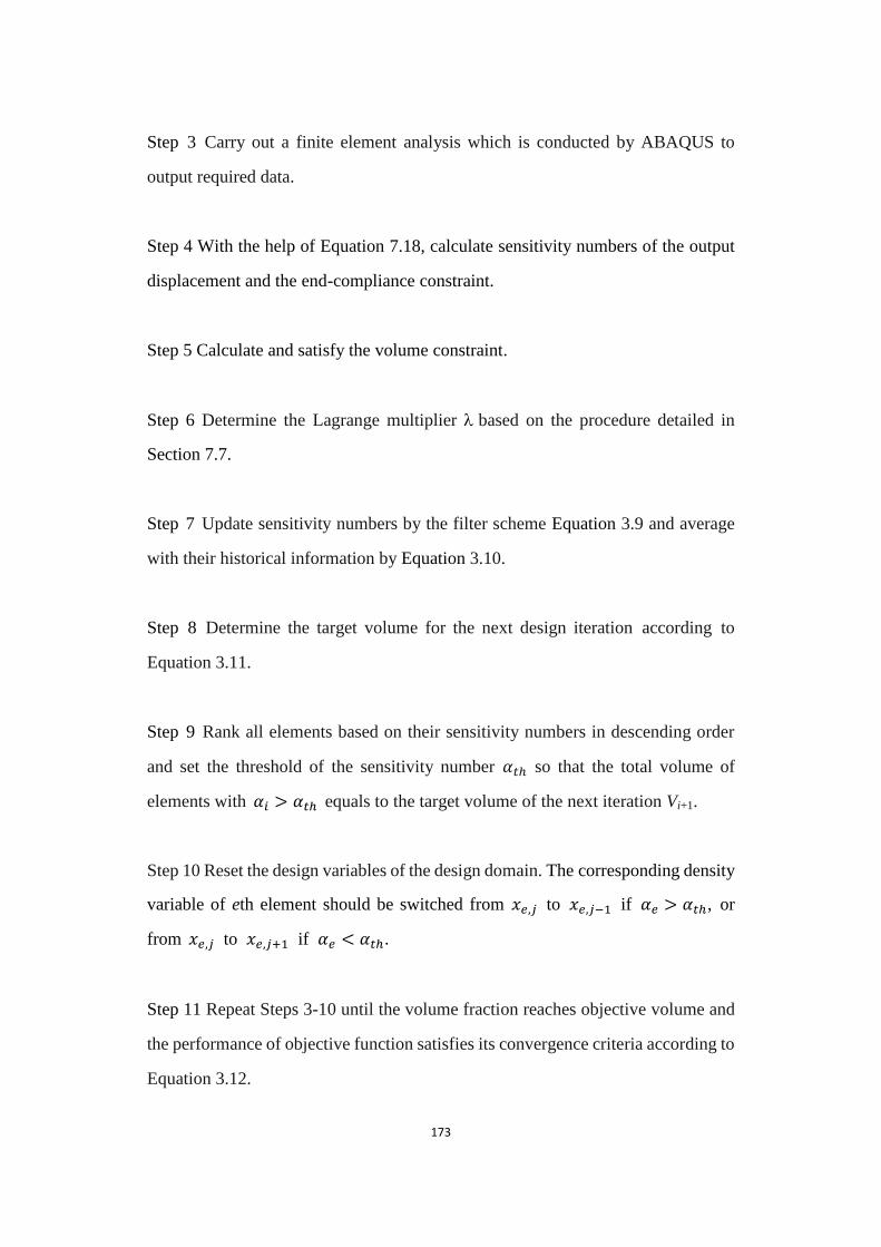
173
Step 3 Carry out a finite element analysis which is conducted by ABAQUS to
output required data.
Step 4 With the help of Equation 7.18, calculate sensitivity numbers of the output
displacement and the end-compliance constraint.
Step 5 Calculate and satisfy the volume constraint.
Step 6 Determine the Lagrange multiplier based on the procedure detailed in
Section 7.7.
Step 7 Update sensitivity numbers by the filter scheme Equation 3.9 and average
with their historical information by Equation 3.10.
Step 8 Determine the target volume for the next design iteration according to
Equation 3.11.
Step 9 Rank all elements based on their sensitivity numbers in descending order
and set the threshold of the sensitivity number 𝛼𝑡ℎ so that the total volume of
elements with 𝛼𝑖 > 𝛼𝑡ℎ equals to the target volume of the next iteration Vi+1.
Step 10 Reset the design variables of the design domain. The corresponding density
variable of eth element should be switched from 𝑒,𝑗 to 𝑒,𝑗−1 if 𝛼𝑒 > 𝛼𝑡ℎ, or
from 𝑒,𝑗 to 𝑒,𝑗+1 if 𝛼𝑒 < 𝛼𝑡ℎ.
Step 11 Repeat Steps 3-10 until the volume fraction reaches objective volume and
the performance of objective function satisfies its convergence criteria according to
Equation 3.12.
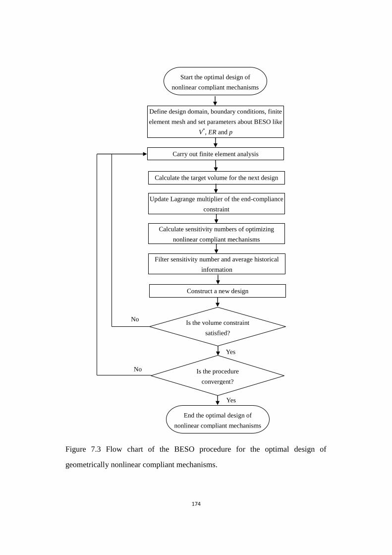
174
Figure 7.3 Flow chart of the BESO procedure for the optimal design of geometrical nonlinear compliant mechanisms
Figure 7.3 Flow chart of the BESO procedure for the optimal design of
geometrically nonlinear compliant mechanisms.
No
No
Yes
Yes
End the optimal design of
nonlinear compliant mechanisms
Start the optimal design of
nonlinear compliant mechanisms
Define design domain, boundary conditions, finite
element mesh and set parameters about BESO like
V*, ER and p
Carry out finite element analysis
Calculate sensitivity numbers of optimizing
nonlinear compliant mechanisms
Filter sensitivity number and average historical
information
Calculate the target volume for the next design
Construct a new design
Is the volume constraint
satisfied?
Is the procedure
convergent?
Update Lagrange multiplier of the end-compliance
constraint

175
7.10 Numerical Examples and Discussion
The proposed optimization method is applied to the design of the benchmark
example with geometrical nonlinearities, namely an inverter mechanism shown in
Figure 4.4. The design domain is also defined as 100mm×100mm and discretized
with 100×100 4-node quadrilateral elements. An input force Fin=5kN to the right
is applied at the center point of the left edge. An artificial spring with stiffness
kout=1kN/mm is attached at the output port to simulate the resistance from the
workpiece, but there is not attached spring at input port. Optimal design expects
that a horizontal displacement △out to the left can be produced from the output port
at the center of the right edge. The material properties are assumed to be Young‟s
modulus E = 100GPa and Poisson‟s ratio ν =0.3. The BESO parameters are
evolutionary rate 𝐸𝑅 = 1 , the filter radius 𝑟𝑚𝑖𝑛 = 5 , penalty exponent
𝑝 = 3 and 𝑚𝑖𝑛 = 0 001.
The optimization procedure starts with the full design with the initial output
displacement ∆𝑜𝑢𝑡0 = 2.244×10
-1mm and end-compliance C
0 = 2.898×10
4Nmm.
Both the end-compliance C and the output displacement ∆𝑜𝑢𝑡 are normalized by
C0 and ∆𝑜𝑢𝑡
0 for the whole process. The volume fraction of the final design is
limited to be 25% of the full design domain and the compliance constraint is set to
be 𝐶 𝐶0⁄ ≤ 5. Figure 7.4 displays the evolution history of the topology of the
compliant inverter with geometrical nonlinearity. De facto regions are relatively
reduced due to a more accurate simulation in the nonlinear analysis, compared with
the final design of linear compliant inverter design. Figure 7.5 shows the evolution
histories of the output displacement, mean compliance and volume fraction. The
convergent solution is achieved with 222 iterations under the convergence factor
of 0.1% for both the output displacement and the mean compliance. Figure 7.6
demonstrates performance of the topology after loading. There is a nonlinear
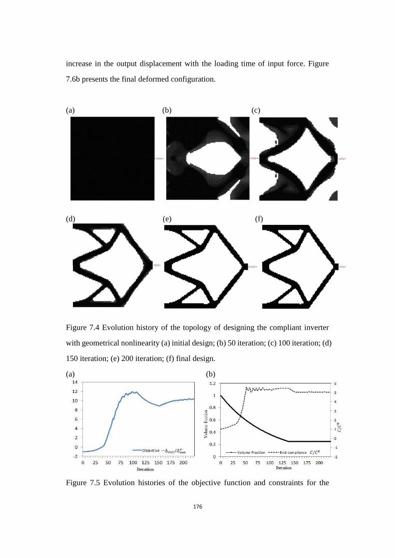
176
increase in the output displacement with the loading time of input force. Figure
7.6b presents the final deformed configuration.
(a) (b) (c)
(d) (e) (f)
Figure 7.4 Evolution history of the topology of designing the compliant inverter with geometrical nonlinearity
Figure 7.4 Evolution history of the topology of designing the compliant inverter
with geometrical nonlinearity (a) initial design; (b) 50 iteration; (c) 100 iteration; (d)
150 iteration; (e) 200 iteration; (f) final design.
(a) (b)
Figure 7.5 Evolution histories of the objective function and constraints for the compliant inverter with geometrical nonlinearity
Figure 7.5 Evolution histories of the objective function and constraints for the
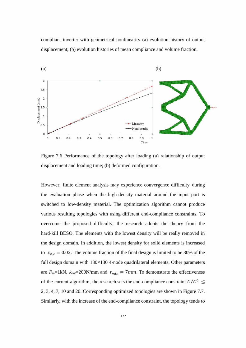
177
compliant inverter with geometrical nonlinearity (a) evolution history of output
displacement; (b) evolution histories of mean compliance and volume fraction.
(a) (b)
Figure 7.6 Performance of the topology after loading
Figure 7.6 Performance of the topology after loading (a) relationship of output
displacement and loading time; (b) deformed configuration.
However, finite element analysis may experience convergence difficulty during
the evaluation phase when the high-density material around the input port is
switched to low-density material. The optimization algorithm cannot produce
various resulting topologies with using different end-compliance constraints. To
overcome the proposed difficulty, the research adopts the theory from the
hard-kill BESO. The elements with the lowest density will be really removed in
the design domain. In addition, the lowest density for solid elements is increased
to 𝑒,2 = 0 02. The volume fraction of the final design is limited to be 30% of the
full design domain with 130×130 4-node quadrilateral elements. Other parameters
are Fin=1kN, kout=200N/mm and 𝑟𝑚𝑖𝑛 = 7 . To demonstrate the effectiveness
of the current algorithm, the research sets the end-compliance constraint 𝐶 𝐶0⁄ ≤
2, 3, 4, 7, 10 and 20. Corresponding optimized topologies are shown in Figure 7.7.
Similarly, with the increase of the end-compliance constraint, the topology tends to
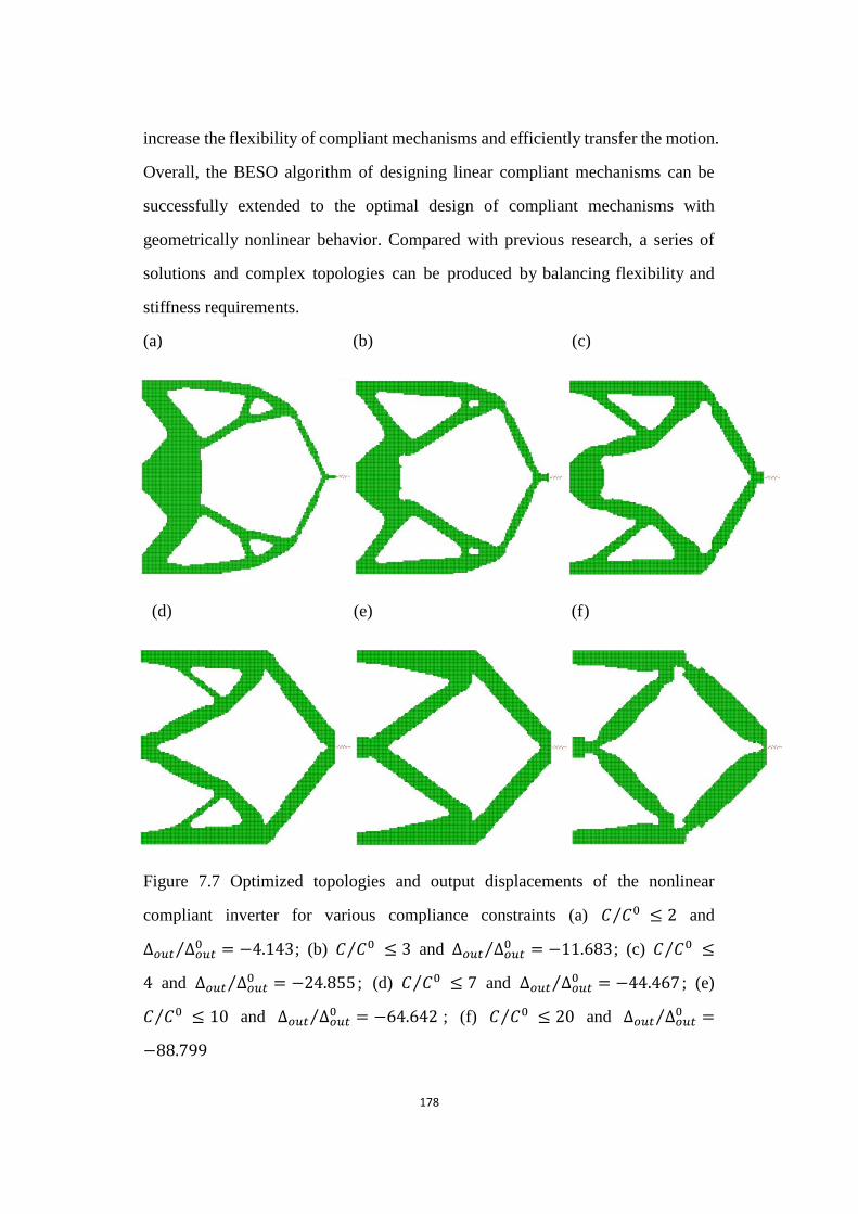
178
increase the flexibility of compliant mechanisms and efficiently transfer the motion.
Overall, the BESO algorithm of designing linear compliant mechanisms can be
successfully extended to the optimal design of compliant mechanisms with
geometrically nonlinear behavior. Compared with previous research, a series of
solutions and complex topologies can be produced by balancing flexibility and
stiffness requirements.
(a) (b) (c)
(d) (e) (f)
Figure 7.7 Optimized topologies and output displacements of the nonlinear compliant inverter for various compliance constraints
Figure 7.7 Optimized topologies and output displacements of the nonlinear
compliant inverter for various compliance constraints (a) 𝐶 𝐶0⁄ ≤ 2 and
∆𝑜𝑢𝑡 ∆𝑜𝑢𝑡0⁄ = −4 143; (b) 𝐶 𝐶0⁄ ≤ 3 and ∆𝑜𝑢𝑡 ∆𝑜𝑢𝑡
0⁄ = −11 683; (c) 𝐶 𝐶0⁄ ≤
4 and ∆𝑜𝑢𝑡 ∆𝑜𝑢𝑡0⁄ = −24 855 ; (d) 𝐶 𝐶0⁄ ≤ 7 and ∆𝑜𝑢𝑡 ∆𝑜𝑢𝑡
0⁄ = −44 467 ; (e)
𝐶 𝐶0⁄ ≤ 10 and ∆𝑜𝑢𝑡 ∆𝑜𝑢𝑡0⁄ = −64 642 ; (f) 𝐶 𝐶0⁄ ≤ 20 and ∆𝑜𝑢𝑡 ∆𝑜𝑢𝑡
0⁄ =
−88 799

179
7.11 Conclusions
The research extends the BESO algorithm of designing linear compliant
mechanisms to the optimal design of compliant mechanisms with geometrically
nonlinear behavior. The optimization problem is re-formulated as maximizing the
flexibility subject to end-compliance and volume constraints. The values of the
displacement vector are obtained iteratively by the Newton-Raphson method with
the tangent stiffness matrix. In addition, the research derives the design sensitivities
for compliant mechanisms undergoing large displacement through the adjoint
method.
Based on the proposed optimization algorithm, numerical examples demonstrate
the validity and effectiveness of designing nonlinear compliant mechanisms using
BESO. Furthermore, with the aid of the hard-kill BESO method, the optimization
design can successfully overcome the convergence difficulty caused by extreme
deformation of low-density elements in the nonlinear finite element analysis. Next,
the optimization method is more computationally efficient and can produce a set
of resulting topologies with the change of the end-compliance constraint. Finally,
one-node hinge does not appear in resulting designs when the nonlinear finite
element analysis is used to capture the real behavior of large-displacement
compliant mechanisms.
However, this research is not intended to provide further comparisons of final
designs with linearity and nonlinearity. This is because linear analysis is not precise
when large deformations are involved, and the used compliance constraints are
actually different in linear and nonlinear analysis.
180
References
Becker, A. A., 2001. Understanding non-linear finite element analysis: Through illustrative
benchmarks, NAFEMS, Glasgow.
Bendsøe, M. P. and Sigmund, O., 2003. Topology Optimization: Theory, Method and Application,
Springer, Berlin.
Bhashyam, G. R., 2002. ANSYS Mechanical - A powerful Nonlinear Simulation Tool, ANSYS Inc,
Canonsburg.
Buhl, T., Pedersen, C. B. W. and Sigmund, O., 2000, "Stiffness design of geometrically nonlinear
structures using topology optimization", Structural and Multidisciplinary Optimization
19(2), 93-104.
Gea, H. C. and Luo, J., 2001, "Topology optimization of structures with geometrical nonlinearities",
Computers and Structures 79(20-21), 1977-1985.
Jinqing, Z. and Xianmin, Z., 2011, "Topology optimization of compliant mechanisms with
geometrical nonlinearities using the ground structure approach", Chinese Journal of
Mechanical Engineering 24(2), 257-263.
Khosravi, P., 2007. Nonlinear finite element analysis and design optimization of thin-walled
structures, Mechanical and Industrial Engineering. Concordia University, Montreal,
Quebec.
Luo, Z. and Tong, L., 2008, "A level set method for shape and topology optimization of
large-displacement compliant mechanisms", International Journal for Numerical Methods
in Engineering 76(6), 862-892.
Pedersen, C. B. W., Buhl, T. and Sigmund, O., 2001, "Topology synthesis of large-displacement
compliant mechanisms", International Journal for Numerical Methods in Engineering
50(12), 2683-2705.
Wriggers, P., 2009. Nonlinear Finite Element Methods, Spinger-Verlag, Berlin.
Zhaokun, L. and Xianmin, Z., 2006. Topology optimization of compliant mechanisms with
geometrically nonlinear. Technology and Innovation Conference, Hangzhou, China.

181
Chapter 8
Conclusions
182
This dissertation has addressed the topology optimization of linear and
geometrically nonlinear compliant mechanisms using a modified bi-directional
evolutionary structural optimization (BESO) method. Conclusions and
achievements are summarized below:
Firstly, a modified BESO method presented in this research changes the original
binary material distribution by introducing intermediate densities. The
evolutionary procedure employs a constant material volume strategy. Elemental
densities are increased or decreased according to a prescribed threshold, updated
gradually by design functions. A filter scheme is applied to resolve the problem of
mesh-dependence. The optimality criteria and solution-convergence algorithms
ensure the final optima to be obtained after an iterative procedure.
The proposed BESO method has been applied to the stiffness optimization of a
cantilever beam in order to demonstrate its feasibility. The final solution proves
that the current BESO method is an efficient optimization tool. Then, this
dissertation extends the proposed BESO method to the optimal design of compliant
mechanisms. The sensitivity analysis is conducted by applying the adjoint method
to solve various design problems such as maximizing geometrical advantage,
mechanical efficiency or output displacement. The new BESO algorithm produces
various designs with the change in the springs‟ constants. Through a large number
of numerical experiments, the research proves the capability and validity of the
new BESO algorithm and considers that attached springs have strong effects on
the topology optimization of compliant mechanisms:
1. Resulting topologies can produce relatively larger output displacement due to
the presence of de facto hinge regions when using the optimization problem
of maximizing mechanical efficiency.
183
2. The optimized geometrical advantage and mechanical efficiency are
decreasing as the spring stiffness increases and the resulting topologies tend
to be simpler. The geometrical advantage tends to be an exponential decrease,
but the mechanical efficiency shows a linear decrease.
3. For topologies based on using the optimization problem of maximizing
output displacement, balancing and promoting the stiffness constants are
beneficial to eliminate de facto hinges. Soft springs can lead to poor structural
connection.
Secondly, this dissertation presents the control of the desired structural stiffness in
the topology design of linear compliant mechanisms. The design problem is
reformulated as maximizing the flexibility of the compliant mechanisms subject
to the mean compliance and volume constraints, considering the mechanism
flexibility and structural stiffness simultaneously. 2D and 3D examples are given
to demonstrate the effectiveness of the BESO algorithm for controlling the
flexibility and hinge-related properties via the desired structural stiffness.
1. A set of different optimized topologies have been produced through the
change of the mean compliance constraint.
2. Using a relatively small compliance constraint can produce hinge-free
topologies. With the increase of the compliance constraint, the optimized
topologies show numerous hinge regions which lie along the force path from
the mechanism input port to the output port.
3. Different with stiffness optimization, material property greatly affects final

184
designs of compliant mechanisms. For an extreme soft workpiece, selecting a
soft material for compliant mechanisms can also preclude the formation of
hinge regions.
Thirdly, this research develops a BESO method for the optimal design of
hinge-free compliant mechanisms. A new objective function is proposed to
maximize the desirable displacement and simultaneously preclude the formation
of hinges. Sensitivity numbers are derived according to the variation of the
objective function with respect to the design variables. Based on the resulting
sensitivity numbers, the BESO procedure is established by gradually removing
and adding elements until an optimal topology is achieved. Several numerical
examples, especially 3D cases, are given to demonstrate the effectiveness of the
proposed BESO method for the design of various hinge-free compliant
mechanisms. There is no any “grey area” in the resulting topologies of compliant
mechanisms owing to the proposed formulation and the binary variables in the
traditional BESO method. Therefore, the current BESO algorithm provides clear
solid-void topologies.
Fourthly, the research extends the idea of designing linear compliant mechanisms,
presenting new formulation and constraint in the optimal design of geometrically
nonlinear compliant mechanisms. The optimization problem is formulated as
maximizing the flexibility subject to the end-compliance and volume constraints.
The adjoint method is employed to derive the sensitivity numbers for compliant
mechanisms undergoing a large deformation. Numerical experiment demonstrates
that the developed algorithm has the capability of designing nonlinear compliant
mechanisms.
1. The convergence difficulty from extreme deformation can be successfully
185
overcome through the hard-kill BESO method in the nonlinear finite element
analysis.
2. The proposed optimization method is more computationally efficient and can
provide a set of optimized topologies as the end-compliance constraint
changes.
3. There is no one-node hinge region generated in resulting designs when the
nonlinear finite element analysis is used to capture the real behavior of
large-displacement compliant mechanisms.
Based on the current achieved outcomes and proposed BESO method, further
research on the topic of topology optimization for compliant mechanisms and
related topics can be carried out to widen the current scope and refine the numerical
algorithms. For instance, a multi-criteria function can be established to optimize
compliant mechanisms with multiple input and output ports based on weighted
global criterion method or weighted sum method. In addition, the normal
distribution function can be considered as the materials to accommodate the use
of multiple materials in the design of compliant mechanisms. The modified BESO
method is also employed to design thermally actuated compliant mechanisms.
Furthermore, piezoelectric and electrostatic principles can be used to achieve the
expected motion for multi-physics actuators in topology optimization of
compliant mechanisms. Further research can also focus on optimizing compliant
actuators of electro-thermo-elasticity via non-uniform Joule heating induced
actuation based on the modified BESO method.
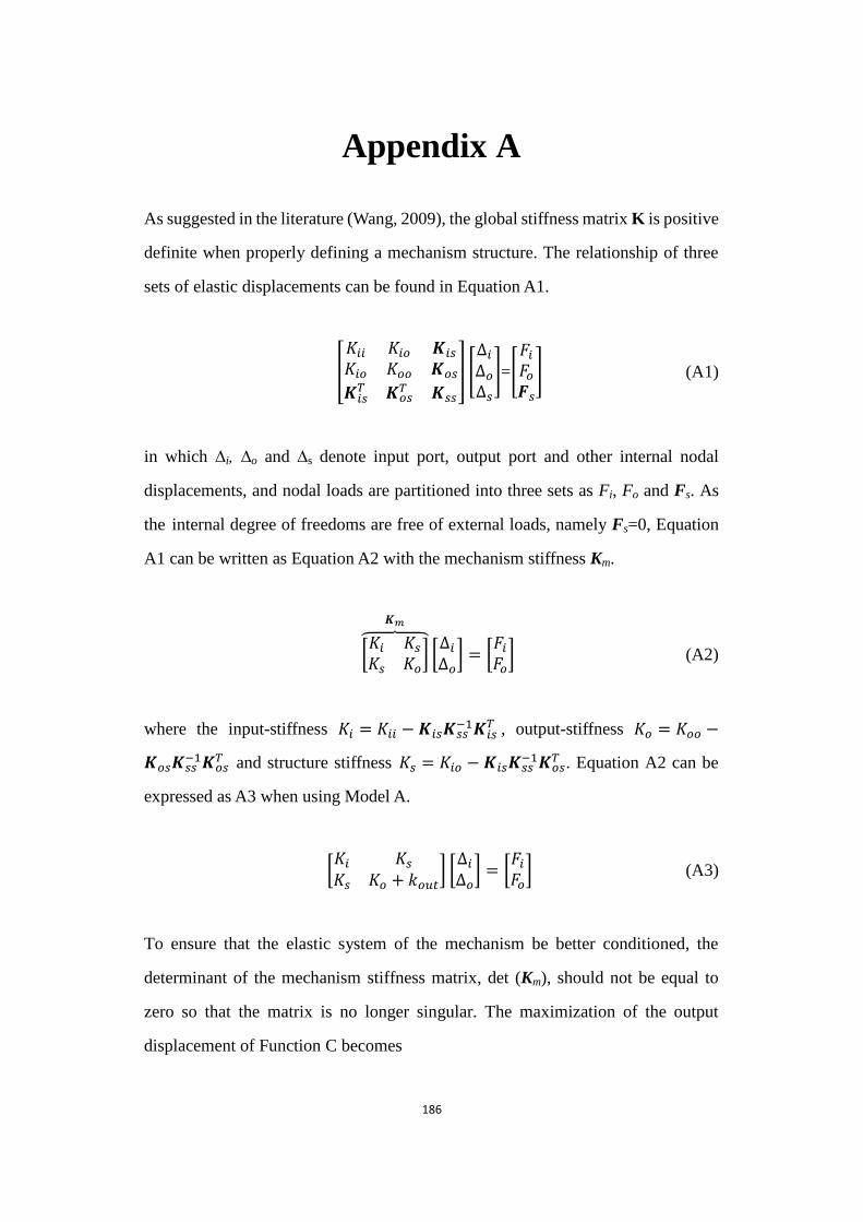
186
Appendix A
As suggested in the literature (Wang, 2009), the global stiffness matrix K is positive
definite when properly defining a mechanism structure. The relationship of three
sets of elastic displacements can be found in Equation A1.
[
𝐾𝑖𝑖 𝐾𝑖𝑜 𝑲𝑖 𝐾𝑖𝑜 𝐾𝑜𝑜 𝑲𝑜 𝑲𝑖 𝑇 𝑲𝑜
𝑇 𝑲
] [
∆𝑖∆𝑜∆
]=[𝐹𝑖𝐹𝑜𝑭
] (A1)
in which ∆i, ∆o and ∆s denote input port, output port and other internal nodal
displacements, and nodal loads are partitioned into three sets as Fi, Fo and Fs. As
the internal degree of freedoms are free of external loads, namely Fs=0, Equation
A1 can be written as Equation A2 with the mechanism stiffness Km.
[𝐾𝑖 𝐾 𝐾 𝐾𝑜
]⏞
𝑲𝑚
[∆𝑖∆𝑜] = [
𝐹𝑖𝐹𝑜] (A2)
where the input-stiffness 𝐾𝑖 = 𝐾𝑖𝑖 −𝑲𝑖 𝑲 −1𝑲𝑖
𝑇 , output-stiffness 𝐾𝑜 = 𝐾𝑜𝑜 −
𝑲𝑜 𝑲 −1𝑲𝑜
𝑇 and structure stiffness 𝐾 = 𝐾𝑖𝑜 −𝑲𝑖 𝑲 −1𝑲𝑜
𝑇 . Equation A2 can be
expressed as A3 when using Model A.
[𝐾𝑖 𝐾 𝐾 𝐾𝑜 + 𝑘𝑜𝑢𝑡
] [∆𝑖∆𝑜] = [
𝐹𝑖𝐹𝑜] (A3)
To ensure that the elastic system of the mechanism be better conditioned, the
determinant of the mechanism stiffness matrix, det (Km), should not be equal to
zero so that the matrix is no longer singular. The maximization of the output
displacement of Function C becomes
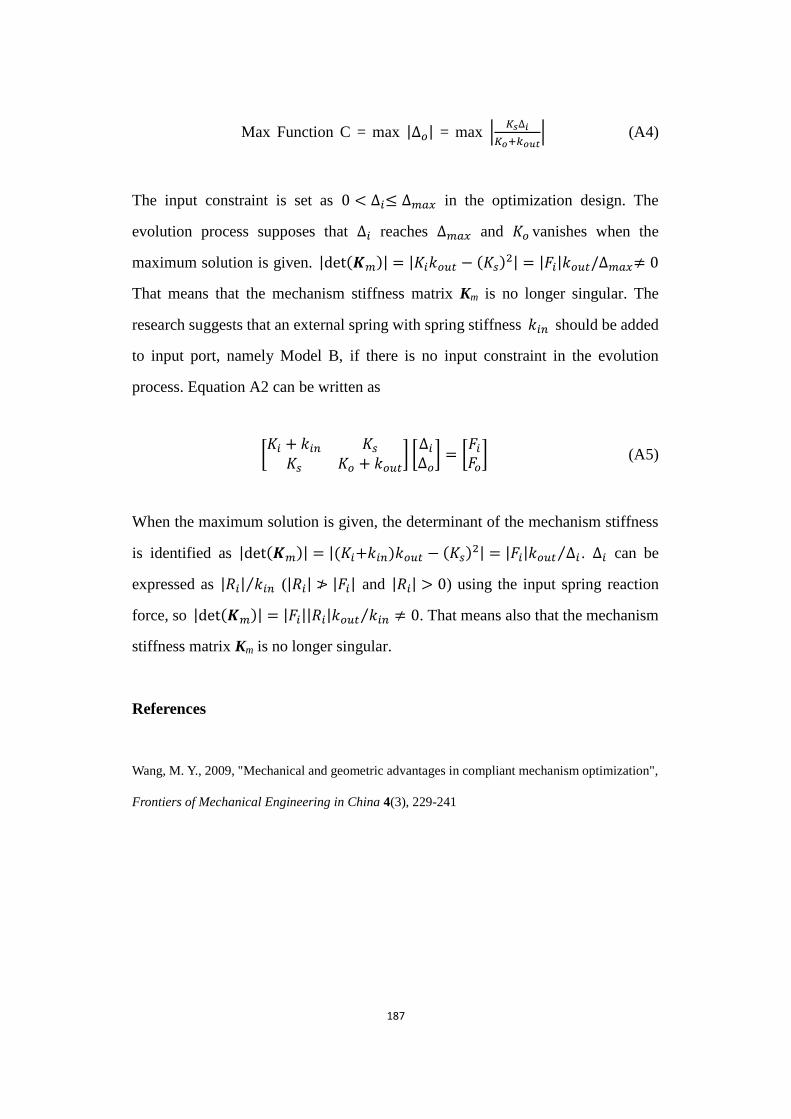
187
Max Function C = max |∆𝑜| = max |𝐾 ∆𝑖
𝐾𝑜+𝑘𝑜 | (A4)
The input constraint is set as 0 < ∆𝑖≤ ∆𝑚𝑎𝑥 in the optimization design. The
evolution process supposes that ∆𝑖 reaches ∆𝑚𝑎𝑥 and 𝐾𝑜 vanishes when the
maximum solution is given. | et(𝑲𝑚)| = |𝐾𝑖𝑘𝑜𝑢𝑡 − (𝐾 )2| = |𝐹𝑖|𝑘𝑜𝑢𝑡/∆𝑚𝑎𝑥 0
That means that the mechanism stiffness matrix Km is no longer singular. The
research suggests that an external spring with spring stiffness 𝑘𝑖𝑛 should be added
to input port, namely Model B, if there is no input constraint in the evolution
process. Equation A2 can be written as
[𝐾𝑖 + 𝑘𝑖𝑛 𝐾 𝐾 𝐾𝑜 + 𝑘𝑜𝑢𝑡
] [∆𝑖∆𝑜] = [
𝐹𝑖𝐹𝑜] (A5)
When the maximum solution is given, the determinant of the mechanism stiffness
is identified as | et(𝑲𝑚)| = |(𝐾𝑖+𝑘𝑖𝑛)𝑘𝑜𝑢𝑡 − (𝐾 )2| = |𝐹𝑖|𝑘𝑜𝑢𝑡 ∆𝑖⁄ . ∆𝑖 can be
expressed as |𝑅𝑖| 𝑘𝑖𝑛⁄ (|𝑅𝑖| |𝐹𝑖| and |𝑅𝑖| > 0) using the input spring reaction
force, so | et(𝑲𝑚)| = |𝐹𝑖||𝑅𝑖|𝑘𝑜𝑢𝑡 𝑘𝑖𝑛 0⁄ . That means also that the mechanism
stiffness matrix Km is no longer singular.
References
Wang, M. Y., 2009, "Mechanical and geometric advantages in compliant mechanism optimization",
Frontiers of Mechanical Engineering in China 4(3), 229-241