compliant shell mechanisms - philosophical...
TRANSCRIPT
Phil. Trans. R. Soc. A (2012) 370, 2010–2026doi:10.1098/rsta.2011.0347
Compliant shell mechanismsBY K. A. SEFFEN*
Department of Engineering, University of Cambridge, Trumpington Street,Cambridge CB2 1PZ, UK
This paper describes a class of lightweight structures known as compliant shellmechanisms. These are novel reconfigurable solutions for advanced structures, such asmorphing shells and deployable membranes. They have local, discrete corrugations, whicharticulate and deform to achieve dramatic changes in the overall shape of the shell. Theunique kinematics are considered by highlighting examples and by performing analysisusing established and novel concepts, and favourable predictions of shape compared withlaboratory models are demonstrated.
Keywords: compliant shell mechanisms; kinematical analysis; lightweight structures
1. Introduction
Compliant shell mechanisms are open, thin-walled, discretely corrugatedstructures, with flat facets or curved regions of shell interconnected by folds orhinge lines. The ‘egg-box’ in figure 1 [1] typifies their unusual properties: theyare soft in certain directions before stiffening considerably, there is sometimeskinematical coupling between modes, they can be much stiffer in other directionsfrom the outset, and they can be simply made—here, they are constructed frompaper card. Their simplicity of form coupled to their unconventional performancemay inspire novel solutions for advanced shell structures, for example, inso-called shape-changing (or ‘morphing’) aircraft [2], where traditional lightweightmaterials such as fibrous composites may falter. Developments in packaging mayalso benefit in structural and compaction terms, so that material usage and,ultimately, waste volume can be minimized.
Their compliance follows from the elastic deformation of the corrugationscoupled to mechanistic articulation about the hinge lines. These are notindependent kinematical modes; rather, they are prescriptive upon one another,resulting in a uniquely defined, low elastic stiffness in the same direction.The distribution and pattern of corrugations within the plane of the shellalso determines any kinematical coupling, with the remaining modes beingconsiderably stiffer. Understanding the relationship between the corrugationproperties and the complete stiffness character of these shells is thereforeimperative, so that their ability to carry loads and change shape safely is ensured.In this study, I begin by concentrating mainly on kinematical concepts, which aim*[email protected]
One contribution of 15 to a Theme Issue ‘Geometry and mechanics of layered structures andmaterials’.
This journal is © 2012 The Royal Society2010
on June 10, 2018http://rsta.royalsocietypublishing.org/Downloaded from
Compliant shell mechanisms 2011
(a) (b) (c)
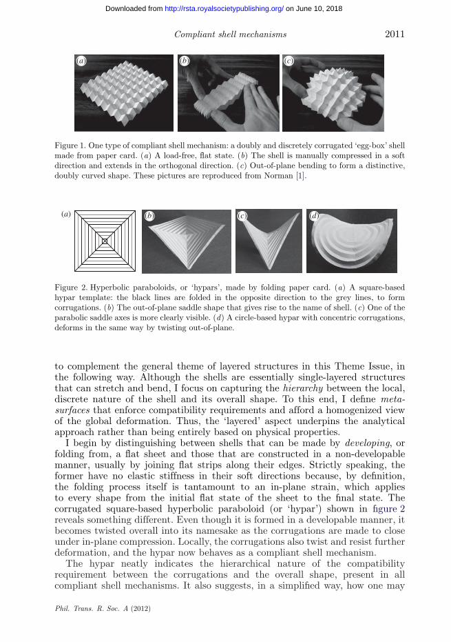
Figure 1. One type of compliant shell mechanism: a doubly and discretely corrugated ‘egg-box’ shellmade from paper card. (a) A load-free, flat state. (b) The shell is manually compressed in a softdirection and extends in the orthogonal direction. (c) Out-of-plane bending to form a distinctive,doubly curved shape. These pictures are reproduced from Norman [1].
(a) (b) (c) (d)
Figure 2. Hyperbolic paraboloids, or ‘hypars’, made by folding paper card. (a) A square-basedhypar template: the black lines are folded in the opposite direction to the grey lines, to formcorrugations. (b) The out-of-plane saddle shape that gives rise to the name of shell. (c) One of theparabolic saddle axes is more clearly visible. (d) A circle-based hypar with concentric corrugations,deforms in the same way by twisting out-of-plane.
to complement the general theme of layered structures in this Theme Issue, inthe following way. Although the shells are essentially single-layered structuresthat can stretch and bend, I focus on capturing the hierarchy between the local,discrete nature of the shell and its overall shape. To this end, I define meta-surfaces that enforce compatibility requirements and afford a homogenized viewof the global deformation. Thus, the ‘layered’ aspect underpins the analyticalapproach rather than being entirely based on physical properties.
I begin by distinguishing between shells that can be made by developing, orfolding from, a flat sheet and those that are constructed in a non-developablemanner, usually by joining flat strips along their edges. Strictly speaking, theformer have no elastic stiffness in their soft directions because, by definition,the folding process itself is tantamount to an in-plane strain, which appliesto every shape from the initial flat state of the sheet to the final state. Thecorrugated square-based hyperbolic paraboloid (or ‘hypar’) shown in figure 2reveals something different. Even though it is formed in a developable manner, itbecomes twisted overall into its namesake as the corrugations are made to closeunder in-plane compression. Locally, the corrugations also twist and resist furtherdeformation, and the hypar now behaves as a compliant shell mechanism.
The hypar neatly indicates the hierarchical nature of the compatibilityrequirement between the corrugations and the overall shape, present in allcompliant shell mechanisms. It also suggests, in a simplified way, how one may
Phil. Trans. R. Soc. A (2012)
on June 10, 2018http://rsta.royalsocietypublishing.org/Downloaded from
2012 K. A. Seffen
begin to quantify these requirements. One may first neglect any local elasticdeformation due to the developable assumption, provided the displacementsare not too large. The intricate three-dimensionality of the shape can then bedecoupled into the average, or middle, surface of the hypar and the effect ofthe corrugations opening or closing. The latter can be represented as an in-planestrain, which permits the shape of the middle surface to be found using one of twoclassical approaches. The first considers an extrinsic view, in which coordinatesets describe the shape of the middle surface in terms of an effective corrugationstrain. The second approach uses intrinsic properties, where the overall shape isdescribed by the Gaussian curvature and the angular defect of the sheet causedby the corrugation behaviour. These methods are described in §2 and are appliedto both the square- and circular-based hypar; fair descriptions of behaviour areobtained despite the simplifying assumptions.
In §3, I present a curved corrugated shell, formed by joining curved stripsof constant width along their adjacent edges. This shell is a true compliantmechanism in which each corrugation elastically deforms from the outset. There isalso coupling between global modes, which is most simply demonstrated duringunidirectional bending: when the shell is pulled apart across the corrugations,it becomes more tightly curved along them, and vice versa. The kinematicalperformance of the middle surface can be considered again in terms of aneffective corrugation strain, which is formulated in terms of the invariantgeodesic curvature of the original shell strips for a compact description. Becausethe shell deforms uniformly and inextensibly throughout, there is no spatialvariation of shape in each corrugation: the strain energy stored in themcan be found easily, and the large displacement stiffness of the shell followswithout difficulty.
This shell also exhibits bidirectional bending into a cap or a saddle shape,and extremely so under larger displacements. This contradicts the generalexpectation of a developable shape such as a cone or a cylinder under asymptoticconditions, but it is an important result because it increases the range ofpossible geometrical transformations. The non-developable deformation is onlyapparent, as it is wrought by the corrugations opening and closing non-uniformly along their lengths. The sense of overall shape is better capturedby thinking about each corrugation deforming between bounding planes ratherthan using the middle surface concept from before. The reason is subtle andwill be explained, and it introduces another conceptual tool for tackling thekinematical hierarchy.
In §4, I consider doubly corrugated shells, returning to the egg-box infigure 1 and comparing it with the well-known developable Miura-ori shell.The egg-box is constructed differently, by interconnecting shaped strips, andthus it has embedded Gaussian curvature. During in-plane deformation, bothexhibit high compliance but opposing Poisson effects: the Miura sheet expandsor contracts in all directions and has a negative Poisson’s ratio, whereasthe egg-box has a positive Poisson’s ratio. This is not unexpected if theyare compared with ordinary materials, but they both show a remarkablereversal of Poisson effects during bending. I do not quantify this behaviour;rather, I describe a method for doing so, which is performed outside ofthis study. Finally, I present a summary and some open research questionsin §5.
Phil. Trans. R. Soc. A (2012)
on June 10, 2018http://rsta.royalsocietypublishing.org/Downloaded from
Compliant shell mechanisms 2013
P
P
x
x
x
y
y
yzz
(a) (b) (c)
u
u
u
uθ
θ2a
2a
a
a
P (x,y,z) P (x,y,z)
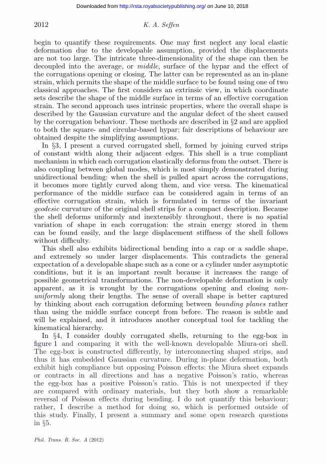
Figure 3. Extrinsic view of the hypar deformation. (a) The general and twisted out-of-plane shape,given by z = kxyxy. (b) A plan view of the symmetrical, in-plane displacement of the outer edges,u, where the corner point P moves along the projected diagonal line to P′. (c) The out-of-planerotation of one of the outside edges, originally x = a, by angle q.
2. Hyperbolic paraboloids
Creating hyperbolic paraboloids, or ‘hypars’, from pleated paper card wasoriginally reported in Demaine et al. [3]. One template for a square hypar isgiven in figure 2a in which sets of hinge lines are scribed onto a flat sheet in fourright-angle quadrants. Folding the hinge lines alternately to some non-zero angleforms the troughs and crests of the corrugations. As this angle increases, thehinge lines move closer together but rotate out of plane, and the original sheetadopts the characteristic saddle shape, as seen in figure 2b,c. A circular hyparwith circumferential corrugations is shown in figure 2d, and it also twists out ofplane as the corrugations are made to close.
(a) Extrinsic view
In figure 3a, the centre of a square hypar of side length 2a is located at theorigin of an orthogonal set of axes, x , y, z . The alignment of the corrugations ischosen such that the out-of-plane shape of the middle surface is described bythe twisted surface z = kxyxy, where kxy is the uniform twisting curvature: this isthe simplest continuous description of shape. Accordingly, the saddle ‘axes’ areparabolae of opposite senses along the lines y = ±x .
The closing of the corrugations is manifest extrinsically as a symmetricalin-plane contraction of the outside edges of the sheet. This is denoted as thedisplacement, u, in figure 3b, which gives rise to an effective corrugation strain, e,measured relative to the original flat state as u/a. The outside edges are assumedto be axially rigid and they must also rotate by angle, q, from the flat duringcontraction (figure 3c). Correspondingly, one of the corners of the sheet, P, movesto a new point, P′, with coordinates (x , y, z) such that
x = a(1 − e), y = a(1 − e), z = kxyxy = kxya2(1 − e)2. (2.1)
It is also evident from figure 3c that cos q = a(1 − e)/a and sin q = z/a.Substituting for z from (2.1), using the identity cos2 q + sin2 q = 1, and
Phil. Trans. R. Soc. A (2012)
on June 10, 2018http://rsta.royalsocietypublishing.org/Downloaded from
2014 K. A. Seffen
x
y
u uxx
2a
(a) (b) (c) (d)
a
p /2+ b
flat
x + bvertex
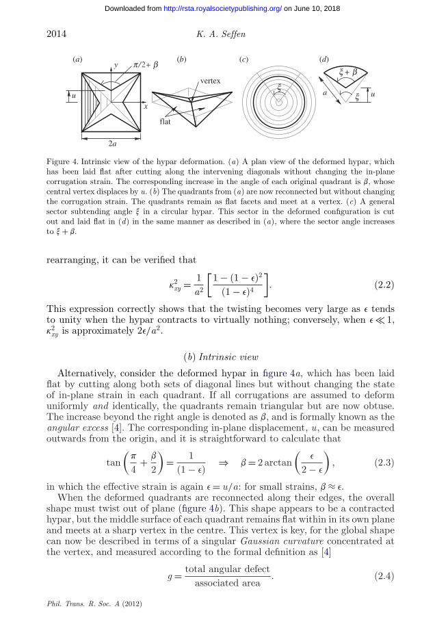
Figure 4. Intrinsic view of the hypar deformation. (a) A plan view of the deformed hypar, whichhas been laid flat after cutting along the intervening diagonals without changing the in-planecorrugation strain. The corresponding increase in the angle of each original quadrant is b, whosecentral vertex displaces by u. (b) The quadrants from (a) are now reconnected but without changingthe corrugation strain. The quadrants remain as flat facets and meet at a vertex. (c) A generalsector subtending angle x in a circular hypar. This sector in the deformed configuration is cutout and laid flat in (d) in the same manner as described in (a), where the sector angle increasesto x + b.
rearranging, it can be verified that
k2xy = 1
a2
[1 − (1 − e)2
(1 − e)4
]. (2.2)
This expression correctly shows that the twisting becomes very large as e tendsto unity when the hypar contracts to virtually nothing; conversely, when e � 1,k2
xy is approximately 2e/a2.
(b) Intrinsic view
Alternatively, consider the deformed hypar in figure 4a, which has been laidflat by cutting along both sets of diagonal lines but without changing the stateof in-plane strain in each quadrant. If all corrugations are assumed to deformuniformly and identically, the quadrants remain triangular but are now obtuse.The increase beyond the right angle is denoted as b, and is formally known as theangular excess [4]. The corresponding in-plane displacement, u, can be measuredoutwards from the origin, and it is straightforward to calculate that
tan(
p
4+ b
2
)= 1
(1 − e)⇒ b = 2 arctan
(e
2 − e
), (2.3)
in which the effective strain is again e = u/a: for small strains, b ≈ e.When the deformed quadrants are reconnected along their edges, the overall
shape must twist out of plane (figure 4b). This shape appears to be a contractedhypar, but the middle surface of each quadrant remains flat within in its own planeand meets at a sharp vertex in the centre. This vertex is key, for the global shapecan now be described in terms of a singular Gaussian curvature concentrated atthe vertex, and measured according to the formal definition as [4]
g = total angular defectassociated area
. (2.4)
Phil. Trans. R. Soc. A (2012)
on June 10, 2018http://rsta.royalsocietypublishing.org/Downloaded from
Compliant shell mechanisms 2015
xy
z(c)axial twisting
middle surfaceof each corrugation
(a) (b)
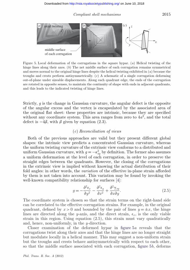
Figure 5. Local deformation of the corrugations in the square hypar. (a) Helical twisting of thehinge lines along their axes. (b) The net middle surface of each corrugation remains symmetricaland moves normal to the original hinge lines despite the helical twisting exhibited in (a) because thetroughs and crests perform antisymmetrically. (c) A schematic of a single corrugation deformingout-of-plane under sizeable displacements. Along each quadrant edge, the ends of the corrugationare rotated in opposite senses, to maintain the continuity of shape with ends in adjacent quadrants,and this leads to the indicated twisting of hinge lines.
Strictly, g is the change in Gaussian curvature, the angular defect is the oppositeof the angular excess and the vertex is encapsulated by the associated area ofthe original flat sheet: these properties are intrinsic, because they are specifiedwithout any coordinate system. This area ranges from zero to 4a2, and the totaldefect is −4b, with b given by equation (2.3).
(c) Reconciliation of views
Both of the previous approaches are valid but they present different globalshapes: the intrinsic view predicts a concentrated Gaussian curvature, whereasthe uniform twisting curvature of the extrinsic view conforms to a distributed anduniform Gaussian curvature, with g = −k2
xy by definition. The former also assumesa uniform deformation at the level of each corrugation, in order to preserve thestraight edges between the quadrants. However, the closing of the corrugationsin the extrinsic view is implied without knowing the actual distribution of theirfold angles: in other words, the variation of the effective in-plane strain affordedby them is not taken into account. This variation may be found by invoking thewell-known compatibility relationship for surfaces [4]:
g = −v2ex
vy2− v2ey
vx2+ v2gxy
vxvy. (2.5)
The coordinate system is chosen so that the strain terms on the right-hand sidecan be correlated to the effective corrugation strains. For example, in the originalquadrant, defined by x > 0 and bounded by the pair of lines y = ±x , the hingelines are directed along the y-axis, and the direct strain, ex , is the only viablestrain in this region. Using equation (2.5), this strain must vary quadraticallyand, hence, non-uniformly, in the y-direction.
Closer examination of the deformed hypar in figure 5a reveals that thecorrugations twist along their axes and that the hinge lines are no longer straightbut modulate locally in a helical manner. This may suggest a non-uniform strainbut the troughs and crests behave antisymmetrically with respect to each other,so that the middle surface associated with each corrugation, figure 5b, deforms
Phil. Trans. R. Soc. A (2012)
on June 10, 2018http://rsta.royalsocietypublishing.org/Downloaded from
2016 K. A. Seffen
uniformly with respect to the original hinge line axis. The reason for the twistedhinge lines becomes apparent in figure 5c: the ends of each corrugation on thediagonal must rotate as the out-of-plane displacements increase.
The intrinsic approach offers a reasonable view of local behaviour but thepredicted global shape is at odds with practice; the extrinsic formulationbetter describes the observed shape of hypar but it does not capture properlythe expediting corrugation strains. The true behaviour is a mixture of bothperformances, and may be revealed in a more elaborate kinematical formulation:for example, in Demaine et al. [5], the twist along each corrugation can beachieved, or relieved, by additionally creasing each pleat for true developablebehaviour. Another underlying reason is due to the inherent, discontinuouscorrugation layout in the square hypar; in the case of the circular hypar withits continuous layout of corrugations, matters can be improved, and this is nowperformed as a final exercise.
(d) Circular hypar
Figure 4c indicates a sector of a circular hypar, which subtends an angle x inthe original flat circle of radius a. An intrinsic viewpoint of the deformed hyparimplies that this angle increases to x + b while conserving the arc length of theouter edge and the straightness of the sector radial lines, as shown in figure 4d.This gives a nominal compressive radial strain, e = u/a, where u is the radialdisplacement of the centre, such that
ax = a(1 − e)(x + b) ⇒ b = ex
1 − e, (2.6)
where b is, again, the angular excess. The Gaussian curvature of the entire hyparconsiders 2p/x sectors and, using equation (2.4),
g = −b(2p/x)A
= − 1A
2pe
1 − e, (2.7)
where A is the associated area. Note that the result is independent of the originalsector angle, and the formulation may therefore be stated in elemental terms,although the Gaussian curvature is still concentrated at the centre of the shell.Consequently, the out-of-plane shape is continuous; if one thinks of a cone beingformed by creating an angular defect in a circular sheet, then the intrinsic viewof the circular hypar must have the opposite shape to the cone.
As far as an extrinsic view is concerned, it is convenient to refer to anaxisymmetrical coordinate system, because the effective corrugation strain actsin the radial direction only and there is a hoop-wise uniformity in shape as wellas inextensibility in this direction. The Gaussian curvature is assumed to beuniform throughout the shell, equal to some negative value of g. The variation ineffective strain can be found from equation (2.5), by writing it in terms of a radialcoordinate, r , and associated tensile strain, er , and integrating twice, to reveal
g = 1r
ver
vr⇒ er = −e = gr2
2. (2.8)
Phil. Trans. R. Soc. A (2012)
on June 10, 2018http://rsta.royalsocietypublishing.org/Downloaded from
Compliant shell mechanisms 2017
(a) (b) (c) (d )
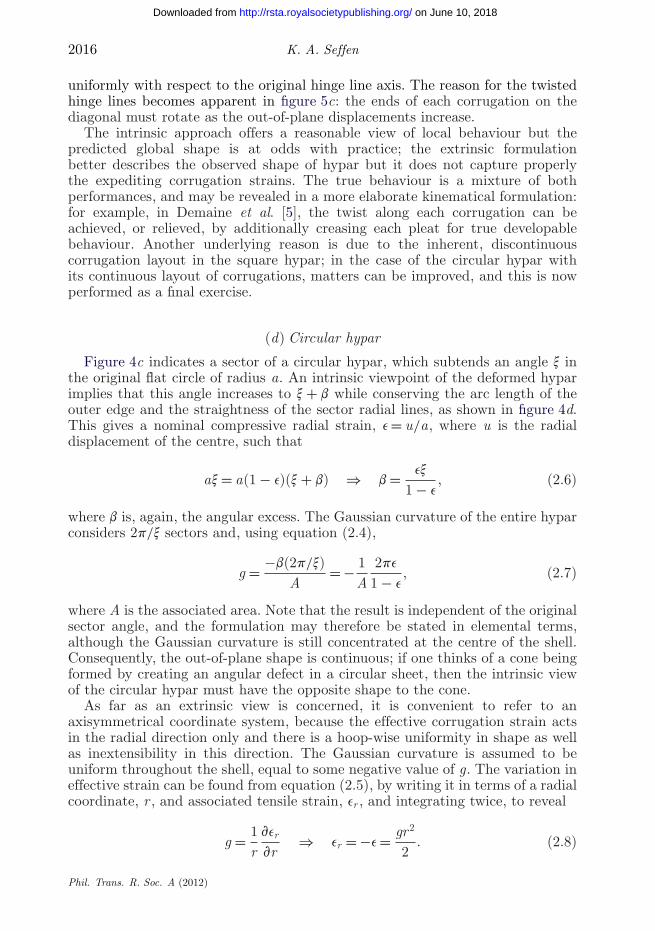
Figure 6. A curved corrugated shell: the top row is reproduced from Norman & Seffen [6] and thebottom row denotes predictions of shape following the solution of equation (3.7). The physical shellis not made from paper card but from plastic. (a) The initial, stress-free shape. (b) Unidirectionalbending, where a transverse extension produces a more tightly coiled structure. Bidirectionalbending follows in (c) and (d) with positive and negative Gaussian curvature overall, respectively.The simulated shapes have w = 10 mm and kg = 1/100 mm−1, and values of q0 and a, defined infigure 8c, as: (a) 50◦, 0◦; (b) 70◦, 0◦; (c) 60◦, +8◦; (d) 60◦, −8◦.
The final strain expression is the simplest possible, assuming that there is nostrain at the hypar centre. Radial compression arises naturally and becomes largertowards the periphery, as observed in practice, and confirmed in Demaine et al. [5].
In closing, these two views deal with different global shapes, but, unlike thesquare hypar, they are both continuous in nature even though they differ in termsof the order of distribution of Gaussian curvature. The extrinsic view, again, mustassume that the Gaussian curvature is distributed throughout the shell, and this isa reasonable interpretation from the practical model. The intrinsic view still workswith a singular Gaussian curvature but now the shape is continuous everywhereelse; essentially, the principal curvature in the radial direction is zero but not inthe hoop-wise direction, and this ensures that the Gaussian curvature outside ofthe vertex can be zero.
3. Curved corrugated shells
Figure 6a shows a corrugated shell initially curved along the corrugation axes andforming an open cylindrical shape. When the shell is pulled apart, it becomes moretightly coiled, and vice versa (figure 6b). But unlike the previous hypars, the shellcan acquire positive or negative Gaussian curvature: depending on the directionof transverse bending, it can become doubly curved with curvatures in the samesense (figure 6c), or adopt the familiar saddle shape with curvatures in oppositesenses (figure 6d).
The kinematics of the simpler case of ‘unidirectional’ bending can be treatedlike the hypars, by assessing the performance of the middle surface of the shell.The shell is constructed by joining together curved strips, similar to the templatein figure 7a, along their edges to form a compact, stress-free stack of strips. Whenthe stack is opened, the global curvature increases as each strip bends into atighter conical section.
Phil. Trans. R. Soc. A (2012)
on June 10, 2018http://rsta.royalsocietypublishing.org/Downloaded from
2018 K. A. Seffen
w
X
θθ
(a) (b) (c)XX
XX
xxxx
1/ g
middle surface
Y
gg
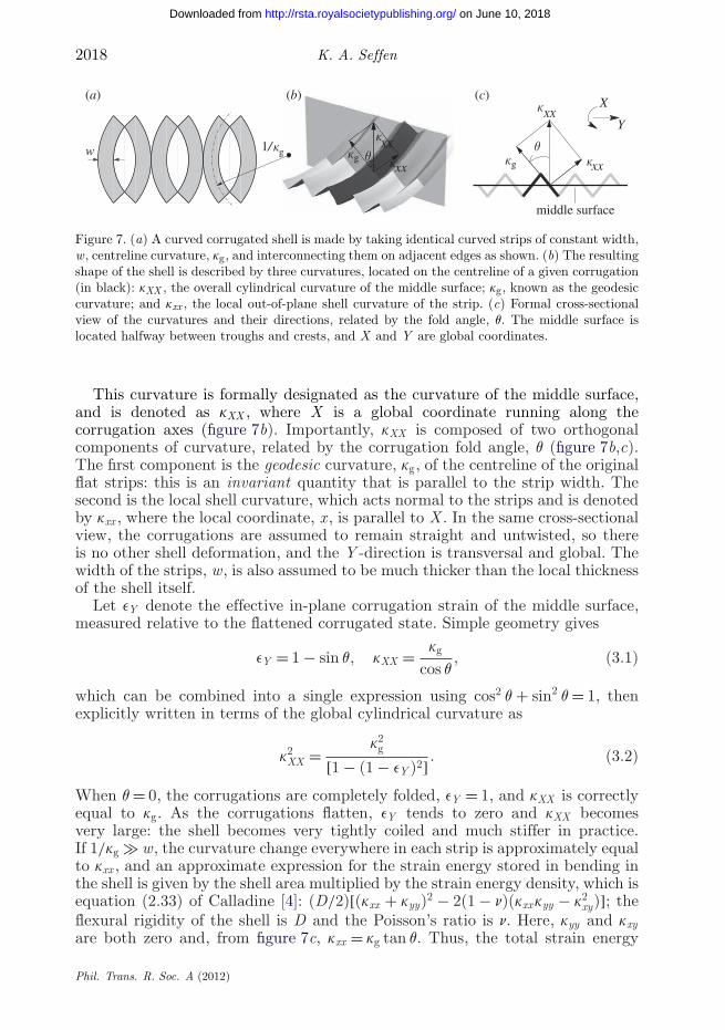
Figure 7. (a) A curved corrugated shell is made by taking identical curved strips of constant width,w, centreline curvature, kg, and interconnecting them on adjacent edges as shown. (b) The resultingshape of the shell is described by three curvatures, located on the centreline of a given corrugation(in black): kXX , the overall cylindrical curvature of the middle surface; kg, known as the geodesiccurvature; and kxx , the local out-of-plane shell curvature of the strip. (c) Formal cross-sectionalview of the curvatures and their directions, related by the fold angle, q. The middle surface islocated halfway between troughs and crests, and X and Y are global coordinates.
This curvature is formally designated as the curvature of the middle surface,and is denoted as kXX , where X is a global coordinate running along thecorrugation axes (figure 7b). Importantly, kXX is composed of two orthogonalcomponents of curvature, related by the corrugation fold angle, q (figure 7b,c).The first component is the geodesic curvature, kg, of the centreline of the originalflat strips: this is an invariant quantity that is parallel to the strip width. Thesecond is the local shell curvature, which acts normal to the strips and is denotedby kxx , where the local coordinate, x , is parallel to X . In the same cross-sectionalview, the corrugations are assumed to remain straight and untwisted, so thereis no other shell deformation, and the Y -direction is transversal and global. Thewidth of the strips, w, is also assumed to be much thicker than the local thicknessof the shell itself.
Let eY denote the effective in-plane corrugation strain of the middle surface,measured relative to the flattened corrugated state. Simple geometry gives
eY = 1 − sin q, kXX = kg
cos q, (3.1)
which can be combined into a single expression using cos2 q + sin2 q = 1, thenexplicitly written in terms of the global cylindrical curvature as
k2XX = k2
g
[1 − (1 − eY )2] . (3.2)
When q = 0, the corrugations are completely folded, eY = 1, and kXX is correctlyequal to kg. As the corrugations flatten, eY tends to zero and kXX becomesvery large: the shell becomes very tightly coiled and much stiffer in practice.If 1/kg � w, the curvature change everywhere in each strip is approximately equalto kxx , and an approximate expression for the strain energy stored in bending inthe shell is given by the shell area multiplied by the strain energy density, which isequation (2.33) of Calladine [4]: (D/2)[(kxx + kyy)2 − 2(1 − n)(kxxkyy − k2
xy)]; theflexural rigidity of the shell is D and the Poisson’s ratio is n. Here, kyy and kxyare both zero and, from figure 7c, kxx = kg tan q. Thus, the total strain energy
Phil. Trans. R. Soc. A (2012)
on June 10, 2018http://rsta.royalsocietypublishing.org/Downloaded from
Compliant shell mechanisms 2019
increases rapidly as the corrugations open owing to the presence of the tan2 qterm, and the corresponding transverse stiffness may be formally ascribed bydifferentiating the strain energy expression twice with respect to q.
The kinematical relationships in equations (3.1) and (3.2) were first determinedby Norman et al. [7], who also proposed a bidirectional bending model usingthe middle surface approach. They assume reasonably that the fold angle, q,varies along the corrugations in the X -direction to yield double curving of themiddle surface. To make the analysis tractable, they also assume that q = q(X)only, which dictates that the troughs and crests are identically open along agiven Y -latitude. It is possible to make the shell bend this way by carefullymanipulating it by hand, but it seems an unnatural mode. The more naturalshape in either figure 6c or d is simply held, and closer inspection suggests that,on a given latitude, the fold angles are the same for the troughs, and for the crests,but different from each other. It is not obvious how the middle surface approachcan be adapted for this, for it subsumes the discrete corrugation nature when adiscrete formulation is needed.
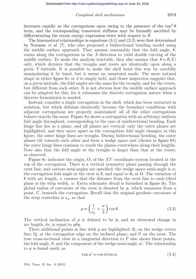
Instead, consider a single corrugation in the shell, which has been extracted inisolation, but which deforms identically because the boundary conditions withadjacent corrugations are properly maintained: all of the other corrugationsbehave exactly the same. Figure 8a shows a corrugation with an arbitrary uniformfold angle throughout, corresponding to the case of unidirectional bending. Eachhinge line lies in a plane, and all planes are vertical: only the outer planes arehighlighted, and they move apart as the corrugation fold angle changes; in thisfigure, the outer hinge lines are troughs. During bidirectional bending, the outerplanes tilt towards each other and form a wedge space and (shown in figure 8b)the outer hinge lines continue to touch the planes everywhere along their lengths.Note also that the fold angle at the troughs is larger than that at the crests,as observed.
Figure 8c indicates the origin, O, of the XY coordinate system located at thetop of the corrugation. There is a vertical symmetry plane passing through thecrest line, and various semi-angles are specified: the wedge space semi-angle is a;the corrugation fold angle at the crest is q, and equal to q0 at O. The variation ofq with arc length, s, ensures that the distance from the crest line to each tiltedplane is the strip width, w. Extra schematic detail is furnished in figure 9a. Theglobal radius of curvature of the crest is denoted by r, which emanates from apoint, C, beneath the corrugation. Recall that the original geodesic curvature ofthe strip centreline is kg, so that
r =(
1kg
+ w2
)cos q. (3.3)
The vertical inclination of r is defined to be h, and an elemental change inarc length, ds, is equal to rdh.
Three additional points in line with r are highlighted: R, on the wedge vertexline; Q, at the corrugation edge on the inclined plane; and P on the crest. Thetrue cross-sectional view in a tangential direction to P also shows these points,the fold angle, q, and the component of the wedge semi-angle, a′. The relationshipto a is found easily as
tan a′ = cos h tan a, (3.4)
Phil. Trans. R. Soc. A (2012)
on June 10, 2018http://rsta.royalsocietypublishing.org/Downloaded from
2020 K. A. Seffen
O
P
s
q
a
q0
(a) (b) (c)
vertex line
Figure 8. Deformation of a single corrugation within a curved corrugated shell. (a) The corrugationhas a uniform fold angle everywhere and the outer hinge lines lie in vertical, parallel planes.(b) Transverse bending of the entire shell causes the outer planes in (a) to tilt: this forms awedge space and the outer hinges maintain contact with these planes, in order to preserve thelocal distortion of the corrugation within the shell. (c) As (b), the degree of transverse bending ismeasured by the wedge space semi-angle, a, the fold angle varies from q0 at the origin, O, to q ata general point, P, at an arc length, s, from O. The origin is located at the top of the corrugation.
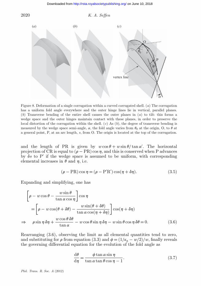
and the length of PR is given by w cos q + w sin q/ tan a′. The horizontalprojection of CR is equal to (r − PR) cos h, and this is conserved when P advancesby ds to P′ if the wedge space is assumed to be uniform, with correspondingelemental increases in q and h, i.e.
(r − PR) cos h = (r − P′R′) cos(h + dh). (3.5)
Expanding and simplifying, one has
[r − w cos q − w sin q
tan a cos h
]cos h
=[
r − w cos(q + dq) − w sin(q + dq)tan a cos(h + dh)
]cos(h + dh)
⇒ r sin h dh + w cos q dq
tan a− w cos q sin h dh − w sin q cos h dq = 0. (3.6)
Rearranging (3.6), observing the limit as all elemental quantities tend to zero,and substituting for r from equation (3.3) and f = (1/kg − w/2)/w, finally revealsthe governing differential equation for the evolution of the fold angle as
dq
dh= f tan a sin h
tan a tan q cos h − 1. (3.7)
Phil. Trans. R. Soc. A (2012)
on June 10, 2018http://rsta.royalsocietypublishing.org/Downloaded from
Compliant shell mechanisms 2021
O
C
R
R
R
Q
Q
Q
P
P
P
w
ws
a
a
ds
h
h +dh
q
q0
r
Figure 9. Schematic elevation of the forward half of the corrugation from figure 8c. The radius ofcurvature of the crest line is r at P, which is inclined at h to the vertical, and emanates from apoint C. Point R lies on the vertex line (figure 8c) and Q is on the edge of the corrugation, sothat they form a true view, which shows the fold angle, q, and the component of the wedge-spacesemi-angle, a′. The true view at the origin shows the true wedge angle, a. All quantities are definedfor transverse bending with respect to positive Gaussian curvature.
This can be solved numerically for specified values of a, f and q0. Predictionsof shape are informally compared with models in figure 6, where the shape of asingle corrugation is computed and then reflected about successive edge planesto form the complete shell. As can be seen, there is a favourable correlation,encouragingly so when the displacements are clearly large.
Finally, note that equation (3.7) can be simplified when a is small by settingthe denominator equal to unity. It may be integrated directly to give
dq
dh≈ f tan a sin h ⇒ q = q0 ∓ f tan a(1 − cos h). (3.8)
The minus sign applies when the shell is bent with positive Gaussian curvature sothat, as expected, the fold angle decreases outwardly from the corrugation centre,and vice versa.
4. Doubly corrugated shells
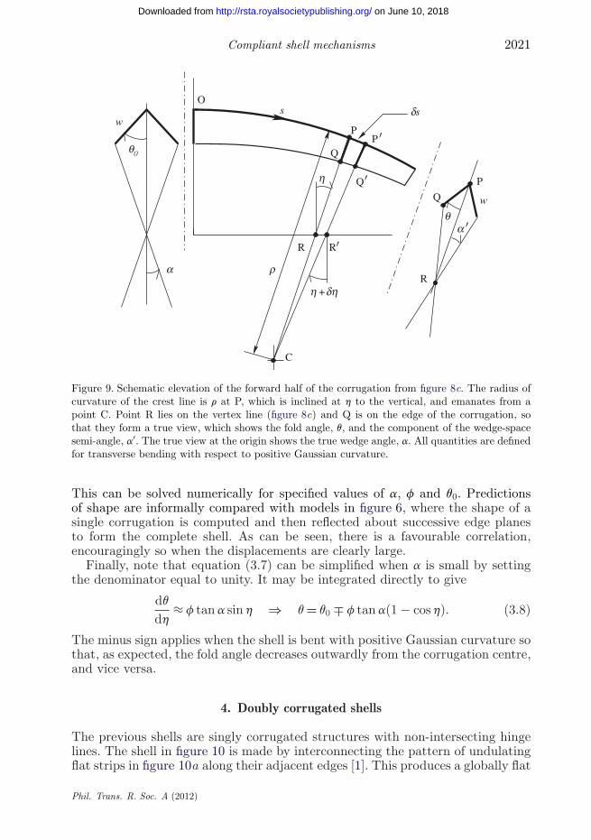
The previous shells are singly corrugated structures with non-intersecting hingelines. The shell in figure 10 is made by interconnecting the pattern of undulatingflat strips in figure 10a along their adjacent edges [1]. This produces a globally flat
Phil. Trans. R. Soc. A (2012)
on June 10, 2018http://rsta.royalsocietypublishing.org/Downloaded from
2022 K. A. Seffen
(a) (b) (c) (d )
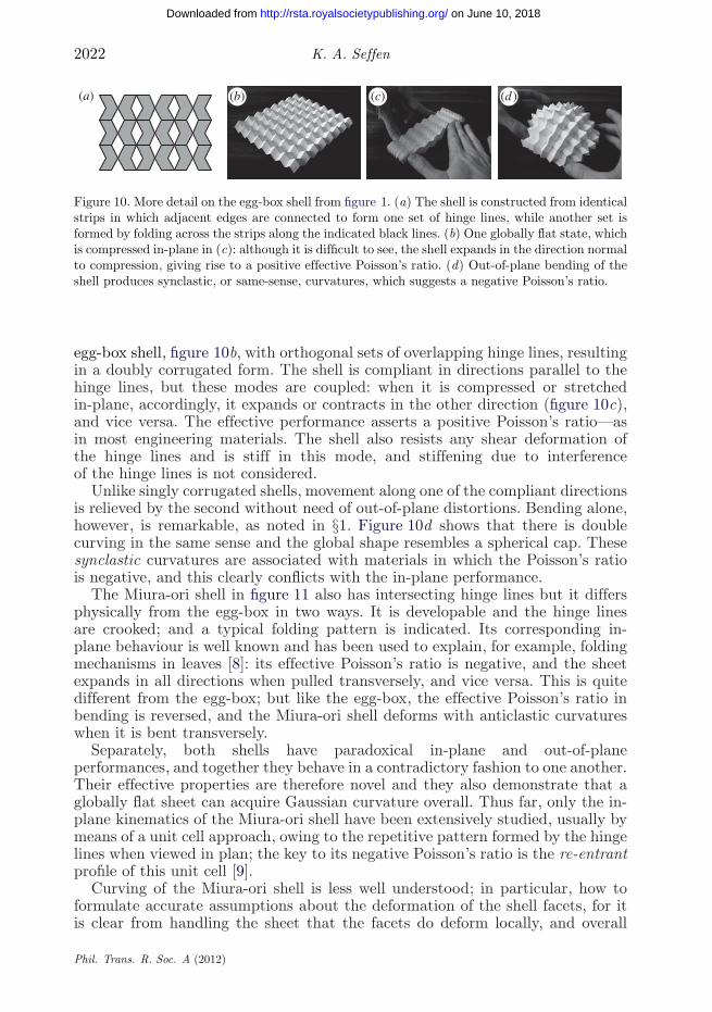
Figure 10. More detail on the egg-box shell from figure 1. (a) The shell is constructed from identicalstrips in which adjacent edges are connected to form one set of hinge lines, while another set isformed by folding across the strips along the indicated black lines. (b) One globally flat state, whichis compressed in-plane in (c): although it is difficult to see, the shell expands in the direction normalto compression, giving rise to a positive effective Poisson’s ratio. (d) Out-of-plane bending of theshell produces synclastic, or same-sense, curvatures, which suggests a negative Poisson’s ratio.
egg-box shell, figure 10b, with orthogonal sets of overlapping hinge lines, resultingin a doubly corrugated form. The shell is compliant in directions parallel to thehinge lines, but these modes are coupled: when it is compressed or stretchedin-plane, accordingly, it expands or contracts in the other direction (figure 10c),and vice versa. The effective performance asserts a positive Poisson’s ratio—asin most engineering materials. The shell also resists any shear deformation ofthe hinge lines and is stiff in this mode, and stiffening due to interferenceof the hinge lines is not considered.
Unlike singly corrugated shells, movement along one of the compliant directionsis relieved by the second without need of out-of-plane distortions. Bending alone,however, is remarkable, as noted in §1. Figure 10d shows that there is doublecurving in the same sense and the global shape resembles a spherical cap. Thesesynclastic curvatures are associated with materials in which the Poisson’s ratiois negative, and this clearly conflicts with the in-plane performance.
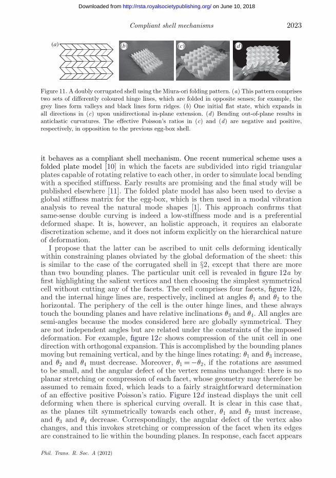
The Miura-ori shell in figure 11 also has intersecting hinge lines but it differsphysically from the egg-box in two ways. It is developable and the hinge linesare crooked; and a typical folding pattern is indicated. Its corresponding in-plane behaviour is well known and has been used to explain, for example, foldingmechanisms in leaves [8]: its effective Poisson’s ratio is negative, and the sheetexpands in all directions when pulled transversely, and vice versa. This is quitedifferent from the egg-box; but like the egg-box, the effective Poisson’s ratio inbending is reversed, and the Miura-ori shell deforms with anticlastic curvatureswhen it is bent transversely.
Separately, both shells have paradoxical in-plane and out-of-planeperformances, and together they behave in a contradictory fashion to one another.Their effective properties are therefore novel and they also demonstrate that aglobally flat sheet can acquire Gaussian curvature overall. Thus far, only the in-plane kinematics of the Miura-ori shell have been extensively studied, usually bymeans of a unit cell approach, owing to the repetitive pattern formed by the hingelines when viewed in plan; the key to its negative Poisson’s ratio is the re-entrantprofile of this unit cell [9].
Curving of the Miura-ori shell is less well understood; in particular, how toformulate accurate assumptions about the deformation of the shell facets, for itis clear from handling the sheet that the facets do deform locally, and overall
Phil. Trans. R. Soc. A (2012)
on June 10, 2018http://rsta.royalsocietypublishing.org/Downloaded from
Compliant shell mechanisms 2023
(b)(a) (c) (d)
Figure 11. A doubly corrugated shell using the Miura-ori folding pattern. (a) This pattern comprisestwo sets of differently coloured hinge lines, which are folded in opposite senses; for example, thegrey lines form valleys and black lines form ridges. (b) One initial flat state, which expands inall directions in (c) upon unidirectional in-plane extension. (d) Bending out-of-plane results inanticlastic curvatures. The effective Poisson’s ratios in (c) and (d) are negative and positive,respectively, in opposition to the previous egg-box shell.
it behaves as a compliant shell mechanism. One recent numerical scheme uses afolded plate model [10] in which the facets are subdivided into rigid triangularplates capable of rotating relative to each other, in order to simulate local bendingwith a specified stiffness. Early results are promising and the final study will bepublished elsewhere [11]. The folded plate model has also been used to devise aglobal stiffness matrix for the egg-box, which is then used in a modal vibrationanalysis to reveal the natural mode shapes [1]. This approach confirms thatsame-sense double curving is indeed a low-stiffness mode and is a preferentialdeformed shape. It is, however, an holistic approach, it requires an elaboratediscretization scheme, and it does not inform explicitly on the hierarchical natureof deformation.
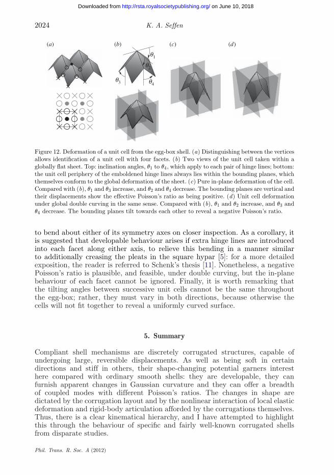
I propose that the latter can be ascribed to unit cells deforming identicallywithin constraining planes obviated by the global deformation of the sheet: thisis similar to the case of the corrugated shell in §2, except that there are morethan two bounding planes. The particular unit cell is revealed in figure 12a byfirst highlighting the salient vertices and then choosing the simplest symmetricalcell without cutting any of the facets. The cell comprises four facets, figure 12b,and the internal hinge lines are, respectively, inclined at angles q1 and q2 to thehorizontal. The periphery of the cell is the outer hinge lines, and these alwaystouch the bounding planes and have relative inclinations q3 and q4. All angles aresemi-angles because the modes considered here are globally symmetrical. Theyare not independent angles but are related under the constraints of the imposeddeformation. For example, figure 12c shows compression of the unit cell in onedirection with orthogonal expansion. This is accomplished by the bounding planesmoving but remaining vertical, and by the hinge lines rotating: q1 and q3 increase,and q2 and q4 must decrease. Moreover, q1 = −q2, if the rotations are assumedto be small, and the angular defect of the vertex remains unchanged: there is noplanar stretching or compression of each facet, whose geometry may therefore beassumed to remain fixed, which leads to a fairly straightforward determinationof an effective positive Poisson’s ratio. Figure 12d instead displays the unit celldeforming when there is spherical curving overall. It is clear in this case that,as the planes tilt symmetrically towards each other, q1 and q2 must increase,and q3 and q4 decrease. Correspondingly, the angular defect of the vertex alsochanges, and this invokes stretching or compression of the facet when its edgesare constrained to lie within the bounding planes. In response, each facet appears
Phil. Trans. R. Soc. A (2012)
on June 10, 2018http://rsta.royalsocietypublishing.org/Downloaded from
2024 K. A. Seffen
(a) (b) (c) (d)
q1
q2
q3 q4
Figure 12. Deformation of a unit cell from the egg-box shell. (a) Distinguishing between the verticesallows identification of a unit cell with four facets. (b) Two views of the unit cell taken within aglobally flat sheet. Top: inclination angles, q1 to q4, which apply to each pair of hinge lines; bottom:the unit cell periphery of the emboldened hinge lines always lies within the bounding planes, whichthemselves conform to the global deformation of the sheet. (c) Pure in-plane deformation of the cell.Compared with (b), q1 and q3 increase, and q2 and q4 decrease. The bounding planes are vertical andtheir displacements show the effective Poisson’s ratio as being positive. (d) Unit cell deformationunder global double curving in the same sense. Compared with (b), q1 and q2 increase, and q3 andq4 decrease. The bounding planes tilt towards each other to reveal a negative Poisson’s ratio.
to bend about either of its symmetry axes on closer inspection. As a corollary, itis suggested that developable behaviour arises if extra hinge lines are introducedinto each facet along either axis, to relieve this bending in a manner similarto additionally creasing the pleats in the square hypar [5]: for a more detailedexposition, the reader is referred to Schenk’s thesis [11]. Nonetheless, a negativePoisson’s ratio is plausible, and feasible, under double curving, but the in-planebehaviour of each facet cannot be ignored. Finally, it is worth remarking thatthe tilting angles between successive unit cells cannot be the same throughoutthe egg-box; rather, they must vary in both directions, because otherwise thecells will not fit together to reveal a uniformly curved surface.
5. Summary
Compliant shell mechanisms are discretely corrugated structures, capable ofundergoing large, reversible displacements. As well as being soft in certaindirections and stiff in others, their shape-changing potential garners interesthere compared with ordinary smooth shells: they are developable, they canfurnish apparent changes in Gaussian curvature and they can offer a breadthof coupled modes with different Poisson’s ratios. The changes in shape aredictated by the corrugation layout and by the nonlinear interaction of local elasticdeformation and rigid-body articulation afforded by the corrugations themselves.Thus, there is a clear kinematical hierarchy, and I have attempted to highlightthis through the behaviour of specific and fairly well-known corrugated shellsfrom disparate studies.
Phil. Trans. R. Soc. A (2012)
on June 10, 2018http://rsta.royalsocietypublishing.org/Downloaded from
Compliant shell mechanisms 2025
Our understanding has been guided by two views. First, consider the entireshape of the shell through its middle surface alone, which is taken to be smoothand continuous. The corrugations are discounted physically but their effect isincorporated as compatible local strains that inform the shape of the middlesurface. Alternatively, take a local view at the level of the corrugation, inisolation from the rest of the shell. This isolated portion, or unit cell, deformsby adhering to the correct boundary conditions on its periphery: these aresymmetrical by definition and correctly reflect the overall shape of the shell.For pure in-plane behaviour, this is relatively straightforward to execute and,typically, the corresponding effective properties can be used to describe the out-of-plane bending properties. However, this is not feasible if these two responsivemodes behave in a contradictory fashion—cf. the conflicting Poisson’s ratios inthe doubly corrugated shells. This has been resolved by proposing that the unitcell is bounded by planes that can move apart or tilt in accordance with the overalldeformation: the unit cell locally deforms and articulates as it moves within thevolumetric space created by the planes; and, to the author’s knowledge, this is anovel approach.
There are many avenues of further research. The shells here are simply madeusing regular template patterns, and it is not difficult to envisage other, possiblyirregular or non-uniform, patterns. These may help to answer what are clearlyopen questions about the influence of the corrugation topology upon the characterof the compliant modes. For example, here I have shown that there is directcoupling between in-plane and out-of-plane modes when the shells are singlycorrugated, but in doubly corrugated cases, the coupling effect is more subtle.It is also important to consider how to make practical shells using traditionalmaterials, such as metals, which oblige because of their ductility and their relativeease of forming. Finally, their complete structural behaviour must be understood:the ability to change shape effectively has to be balanced by the structure beingstiff in other modes. These and other questions are currently being answered bythe Advanced Structures Group at Cambridge.
K.A.S. gratefully acknowledges the invitation from the editor to write this paper for this ThemeIssue. Mark Schenk and Alex Norman are thanked for their photographs of doubly corrugatedshells, and the former is thanked for many stimulating discussions on this paper.
References
1 Norman, A. D. 2009 Multistable and morphing corrugated shell structures. PhD thesis,University of Cambridge, Cambridge, UK.
2 Weiss, P. 2003 Wings of change: shape-shifting aircraft may ply future skyways. Sci. News 164,359. (doi:10.2307/4018925).
3 Demaine, E. D., Demaine, M. L. & Lubiw, A. 1999 Polyhedral sculptures with hyperbolicparaboloids. In Proc. 2nd Annual Conf. of BRIDGES: Mathematical Connections in Art, Musicand Science, Southwestern College, Winfield, KS, 30 July–1 August 1999 (ed. R. Sarhangi),pp. 91–100. See http://erikdemaine.org/papers/BRIDGES99/paper.pdf.
4 Calladine, C. R. 1983 Theory of shell structures. Cambridge, UK: Cambridge University Press.5 Demaine, E. D., Demaine, M. L., Hart, V., Price, G. N. & Tachi, T. 2011. (Non)existence
of pleated folds: how paper folds between creases. Graphs Comb. 27, 377–397. (doi:1007/s00373-011-1025-2)
6 Norman, A. D., Seffen, K. A. & Guest, S. D. 2008 Multistable corrugated shells. Proc. R. Soc.A, 464, 1653–1672. (doi:10.1098/rspa.2007.0216)
Phil. Trans. R. Soc. A (2012)
on June 10, 2018http://rsta.royalsocietypublishing.org/Downloaded from
2026 K. A. Seffen
7 Norman, A. D., Seffen, K. A. & Guest, S. D. 2009 Morphing of curved corrugated shells. Int.J. Solids Struct. 46, 1624–1633. (doi:10.1016/j.ijsolstr.2008.12.009)
8 De Focatiis, D. S. A. & Guest, S. D. 2002 Deployable membranes designed from folding treeleaves. Phil. Trans. R. Soc. Lond. A 360, 227–238. (doi:10.1098/rsta.2001.0928)
9 Mahadevan, L. & Rica, S. 2005 Self-organised origami. Science 307, 1740. (doi:10.1126/science.1105169)
10 Schenk, M. 2008 Textured shell structures. First-year PhD report, University of Cambridge,Cambridge, UK.
11 Schenk, M. 2012 Textured shell structures. PhD thesis, University of Cambridge,Cambridge, UK.
Phil. Trans. R. Soc. A (2012)
on June 10, 2018http://rsta.royalsocietypublishing.org/Downloaded from