topology optimization of compliant suspension mechanismsjtalliso/research/csto.pdf · topology...
TRANSCRIPT
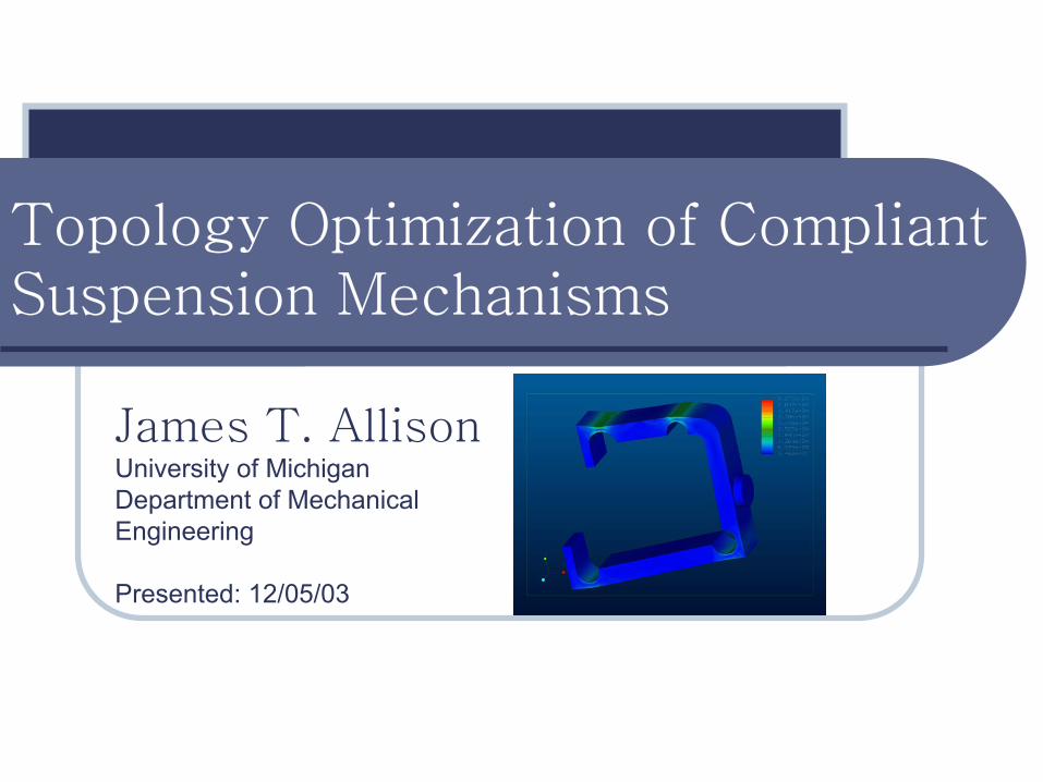
Topology Optimization of Compliant Suspension Mechanisms
James T. AllisonUniversity of MichiganDepartment of Mechanical Engineering
Presented: 12/05/03

CSTO Project
Objective:Develop a generalized method for the optimization of a Compliant Suspension Topology.
Contributors:James Allison (Optimal Design Laboratory)
Michael Cherry (Compliant System Design Laboratory)
Zachary Kreiner (Compliant System Design Laboratory)
CSTO Project
Overview:Compliant Mechanisms
Compliant Suspensions
Topology Optimization
Case Study
Optimization ModelMultiple Objective Functions
Genetic Algorithms
Results
Compliant Mechanisms
What is a compliant mechanism?Device that utilizes elastic deformation of material to produce a desired motion or force transmission instead of rigid linkages and joints.
Why use compliant mechanisms?Fewer parts (easy manufacture/assembly/ good reliability)
Stiffness and damping can be built into the mechanism. Energy is stored as strain energy in the material.
Larger design space: enables the design of novel mechanisms.
Compliant Suspensions
Suspensions provide stiffness and usually damping for a motion along a prescribed path. Examples include:
Automotive suspensions
Industrial machinery
Mountain bike suspensions
Compliant suspensions rely on elastic deformation of the system to provide a desired motion when a particular force is applied.
Compliant Mechanisms
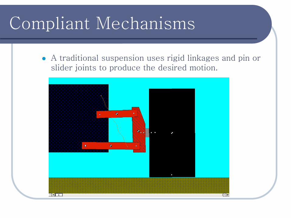
A traditional suspension uses rigid linkages and pin or slider joints to produce the desired motion.
Compliant Mechanisms
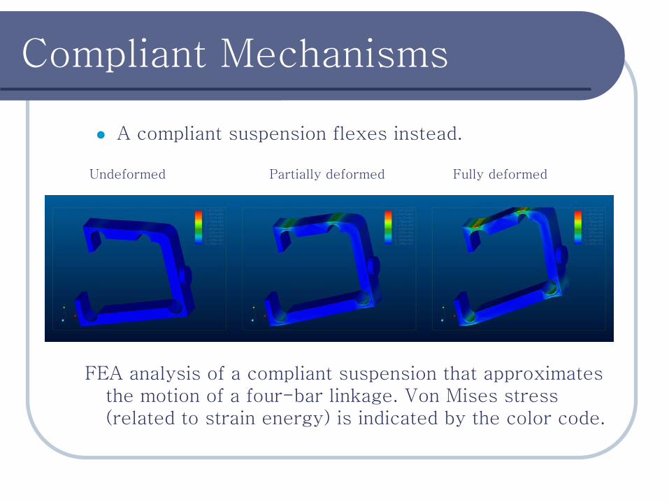
A compliant suspension flexes instead.
FEA analysis of a compliant suspension that approximates the motion of a four-bar linkage. Von Mises stress (related to strain energy) is indicated by the color code.
Undeformed Partially deformed Fully deformed
Topology Optimization
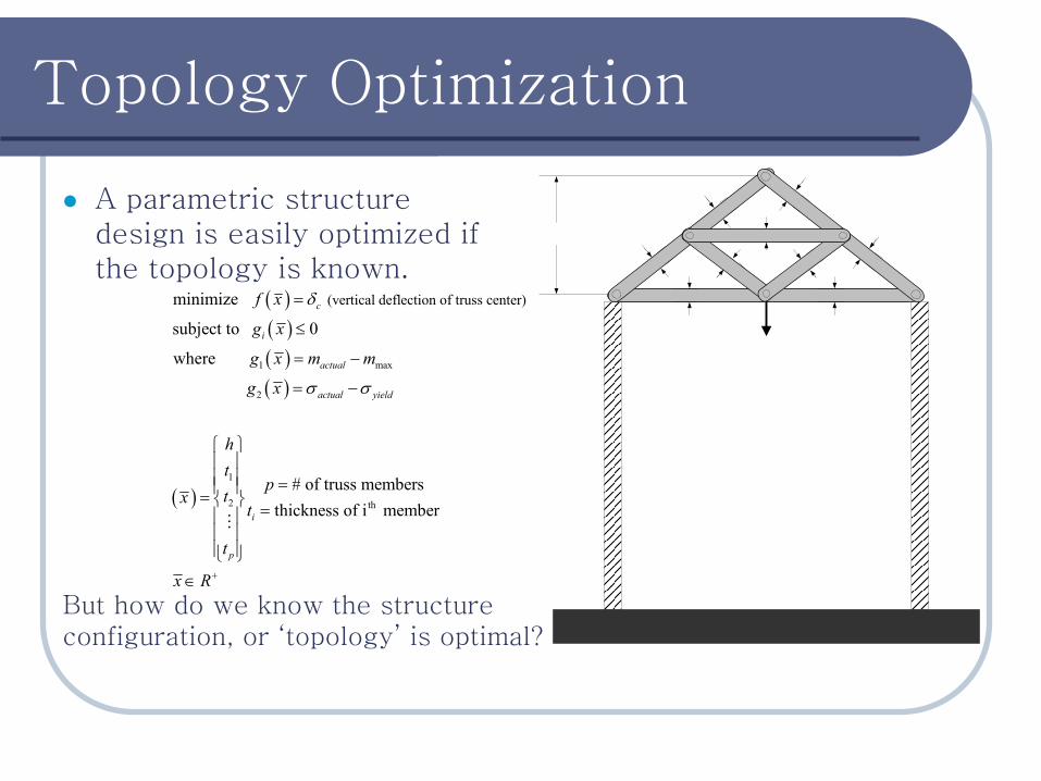
A parametric structure design is easily optimized if the topology is known.
( )( )( )( )
( )
1 max
2
1
2
(vertical deflection of truss center) minimize
subject to 0
where
# of truss membersthickness of
c
i
actual
actual yield
i
p
f x
g x
g x m m
g x
ht
ptxt
t
δ
σ σ
=
≤
= −
= −
= = =
Mth i member
x R+∈
But how do we know the structure configuration, or ‘topology’ is optimal?
Topology Optimization
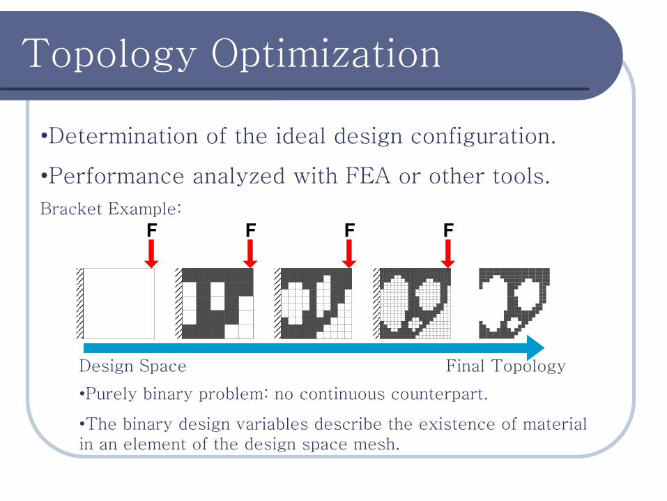
•Determination of the ideal design configuration.
•Performance analyzed with FEA or other tools.
Bracket Example:
Design Space Final Topology
•Purely binary problem: no continuous counterpart.
•The binary design variables describe the existence of material in an element of the design space mesh.
Case Study
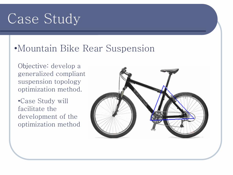
•Mountain Bike Rear Suspension
Objective: develop a generalized compliant suspension topology optimization method.
•Case Study will facilitate the development of the optimization method
Case Study
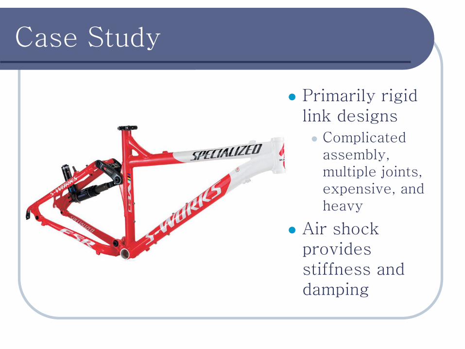
Primarily rigid link designs
Complicated assembly, multiple joints, expensive, and heavy
Air shock provides stiffness and damping
Case Study
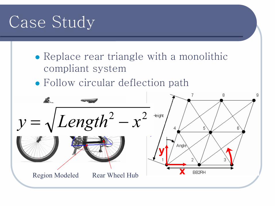
Replace rear triangle with a monolithic compliant system
Follow circular deflection path
Rear Wheel HubRegion Modeled
Seat Tube22 xLengthy −=
x
y
Case Study
Simplifying assumptions made initially to develop basic method:
2D model (torsion and out-of-plane forces ignored)
Rough mesh (must be scalable)
Neglect stress initially.
Ignore buckling and fatigue.
Concentrate on path accuracy, system mass, and longitudinal rigidity.
Optimization Model
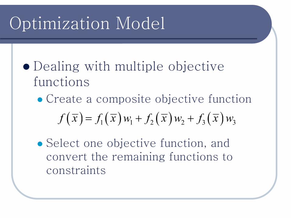
Dealing with multiple objective functions
Create a composite objective function
Select one objective function, and convert the remaining functions to constraints
( ) ( ) ( ) ( )1 1 2 2 3 3f x f x w f x w f x w= + +
Optimization Model
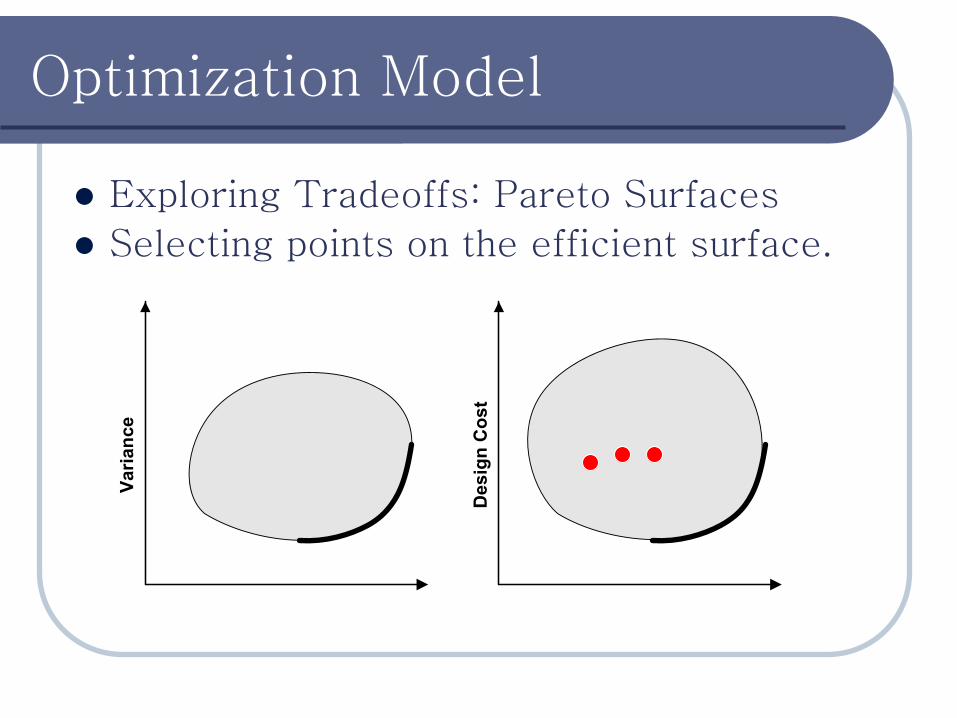
Exploring Tradeoffs: Pareto Surfaces
Selecting points on the efficient surface.
Varia
nce
Des
ign
Cos
t
Optimization Model
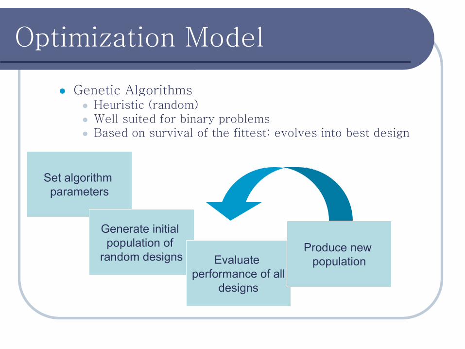
Genetic AlgorithmsHeuristic (random)Well suited for binary problemsBased on survival of the fittest: evolves into best design
Set algorithm parameters
Generate initial population of
random designs Evaluate performance of all
designs
Produce new population
Optimization Model
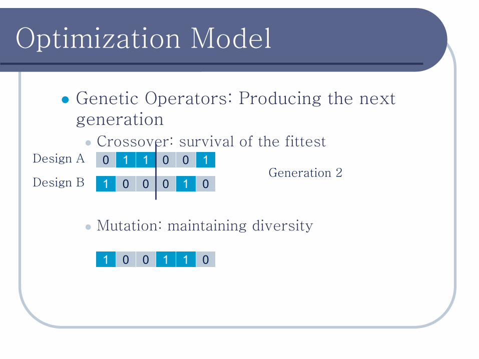
Genetic Operators: Producing the next generation
Crossover: survival of the fittest
Mutation: maintaining diversity
1 0
1
01 00
00110Design A
Design BGeneration 1Generation 2
1 001 00 1
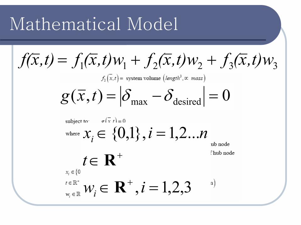
Mathematical Model
332211 ,t)wx(f,t)wx(f,t)wx(f,t)xf( ++=
0),( desiredmax =−= δδtxg
∈xi
3,2,1,
...2,1},1,0{
=∈
∈
=∈
+
+
iwt
nix
i
i
RR
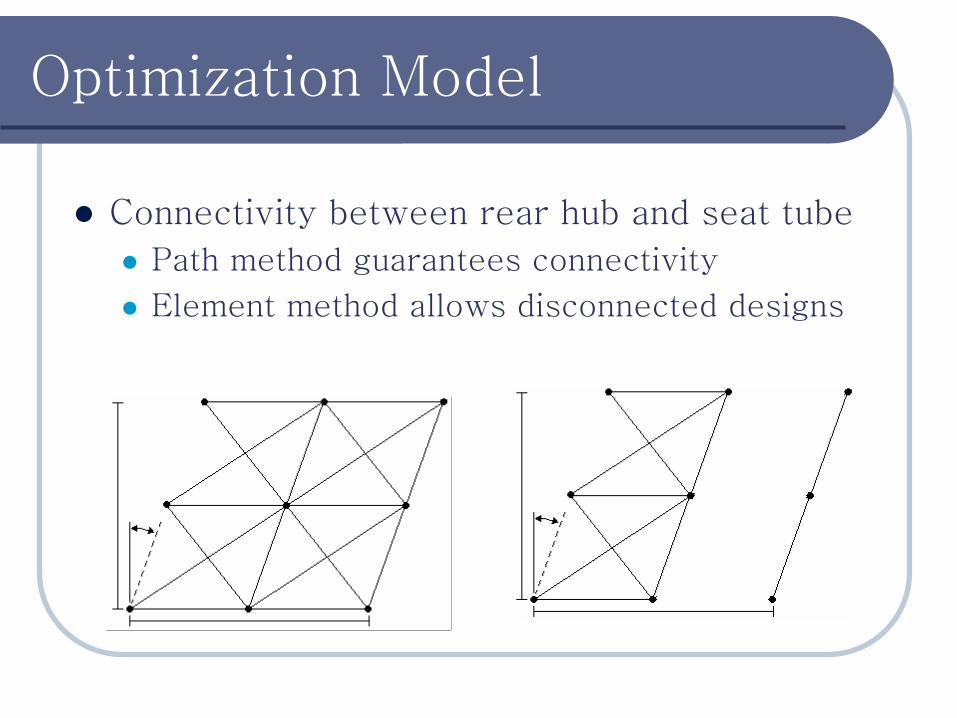
Optimization Model
Connectivity between rear hub and seat tube
Path method guarantees connectivity
Element method allows disconnected designs
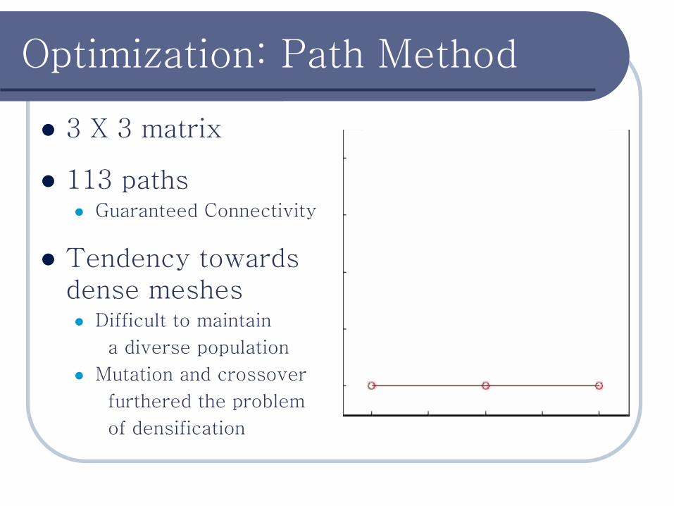
Optimization: Path Method
3 X 3 matrix
113 pathsGuaranteed Connectivity
Tendency towards dense meshes
Difficult to maintain
a diverse population
Mutation and crossover
furthered the problem
of densification
Best Path Method Design
Longitudinal Location (in)V
ertic
al L
ocat
ion
(in)
Best Path Method Design
Longitudinal Location (in)
Ver
tical
Loc
atio
n (in
)
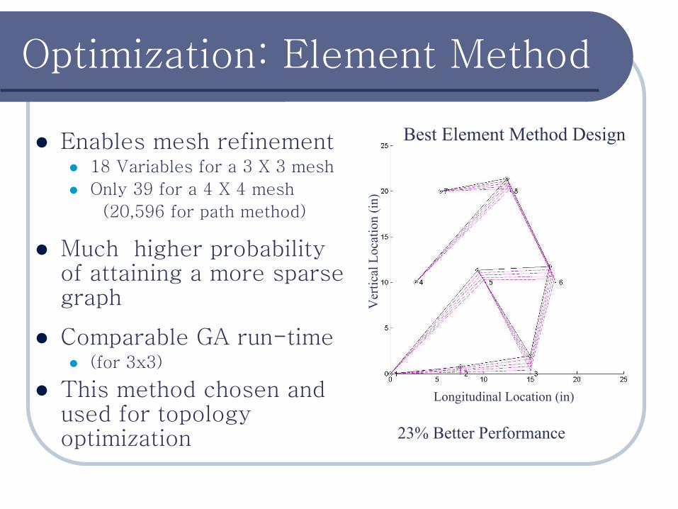
Optimization: Element Method
Enables mesh refinement18 Variables for a 3 X 3 mesh
Only 39 for a 4 X 4 mesh
(20,596 for path method)
Much higher probability of attaining a more sparse graph
Comparable GA run-time(for 3x3)
This method chosen and used for topology optimization 23% Better Performance
Best Element Method Design
Longitudinal Location (in)
Ver
tical
Loc
atio
n (in
)
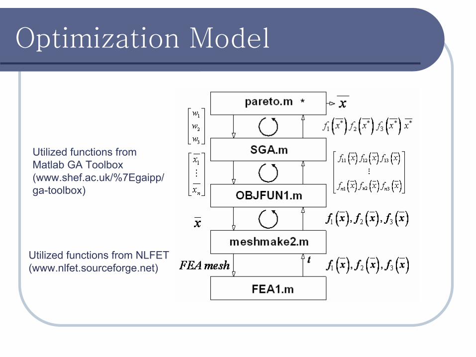
Optimization Model
*
Utilized functions from NLFET (www.nlfet.sourceforge.net)
Utilized functions from Matlab GA Toolbox (www.shef.ac.uk/%7Egaipp/ga-toolbox)

Design Evolution
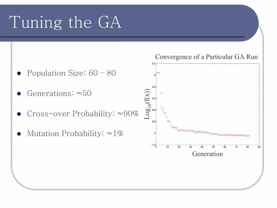
Tuning the GA
Population Size: 60 – 80
Generations: ≈50
Cross-over Probability: ≈90%
Mutation Probability: ≈1%
Generation
Best = 0.09019
Log 10
(f(x
))
Convergence of a Particular GA Run
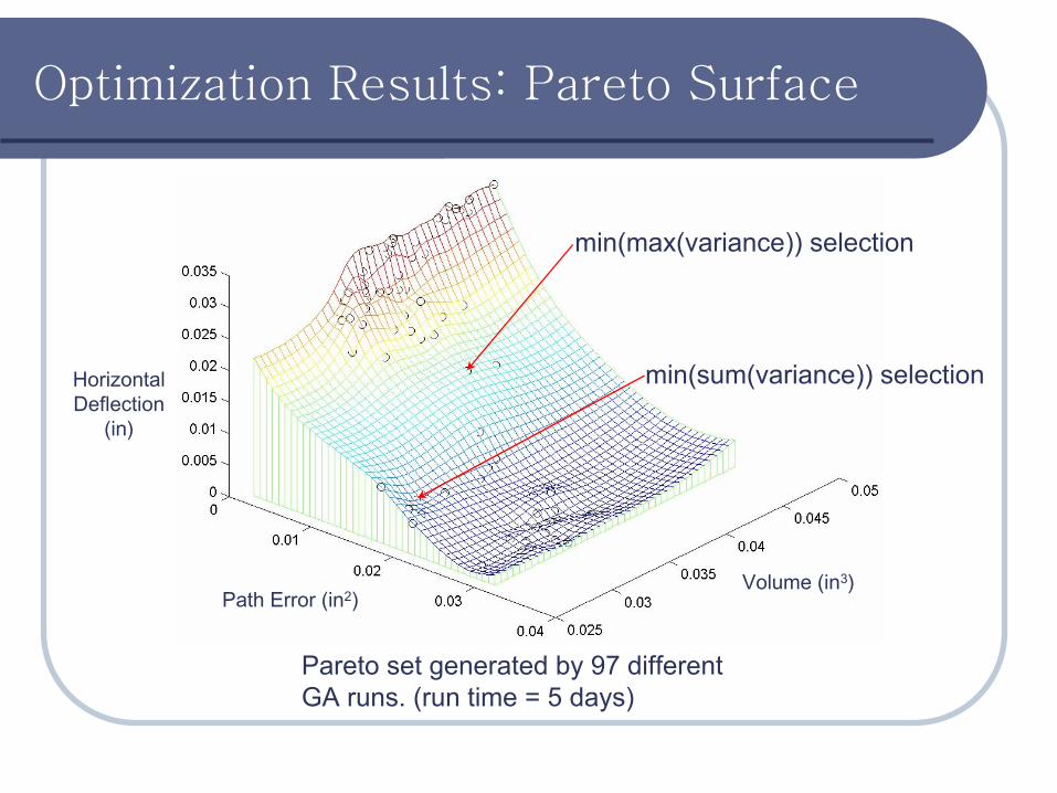
Optimization Results: Pareto Surface
Path Error (in2)
Horizontal Deflection
(in)
Volume (in3)
min(max(variance)) selection
min(sum(variance)) selection
Pareto set generated by 97 different GA runs. (run time = 5 days)
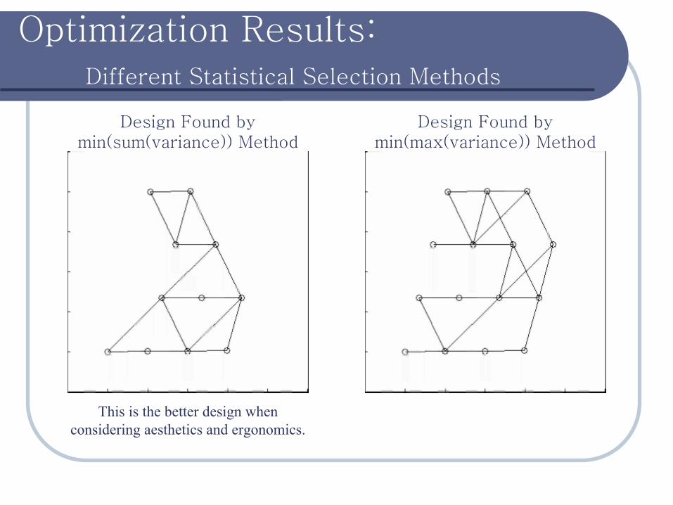
Optimization Results:Different Statistical Selection Methods
Design Found by min(max(variance)) Method
Design Found by min(sum(variance)) Method
This is the better design when considering aesthetics and ergonomics.
Discussion of Results
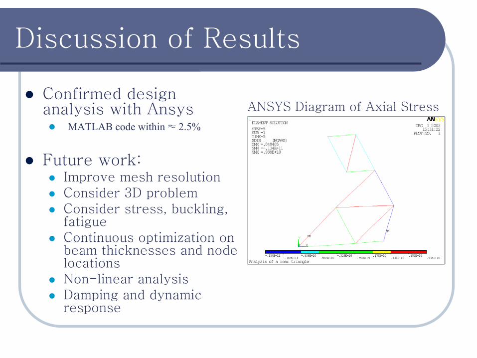
Confirmed design analysis with Ansys
MATLAB code within ≈ 2.5%
Future work:Improve mesh resolutionConsider 3D problemConsider stress, buckling, fatigueContinuous optimization on beam thicknesses and node locationsNon-linear analysisDamping and dynamic response
ANSYS Diagram of Axial Stress

Questions will now be addressed.
More information will soon be available at:
www.umich.edu/~jtalliso
Direct further questions to: