toa exes-6000 intercom system installation hand book
TRANSCRIPT

TOA EXES-6000 INTERCOM SYSTEMCentral Processing Unit for Single Exchange
CP-62INSTALLATION HAND BOOK
TOA ELECTRIC CO., LTD.
EXES-6000 CP-62
KOBE, JAPAN133-21-079-2
For

CONTENTSPage
INTRODUCTION TO THE INSTALLATION MANUAL FOR EXES-6000FUNCTIONS WHICH REQUIRE ADDITIONAL UNITS
- PART 1. OPERATING OF CP UNIT AND NO.200 PROGRAMMING -
1. Precautions for Installation of CP-62Initial CP-62 set up2.
23
567811121518
3. Troubleshooting4. CP-62 DIP Switches for Function Selection5. Setting DIP Switch Positions for Four (4) different types of Dial Operation6. Dip Switch Selection and Station No.200 Programming for Each Function7. Function Code Table for Station No.200 Programming8. Station No.200 Programming for Each Function
[Function Group A]8-1 Executive Priority8-2 Continuous Calling Tone8-3 Stations Allowed Access to All Call8-4 Stations Allowed Access to Conference8-5 Automatic Access to Paging8-6 Stations Allowed Access to One-shot Make Output8-7 Stations Allowed Access to Make/Break Output8-8 Stations Allowed Access to 8 Selectable (One-shot Make) or Decimal Output8-9 Stations Allowed Access to 4 Decimal Digits Output
[Function Group B]8-10 Secretary Transfer8-11 Master/Sub Relationship8-12 Group Hunting
[Function Group C]8-13 Paging Zone8-14 Group Blocking 1 : Establishment of each Group8-15 Calling Party Indication (Lamp Type)
[Function Group D]8-16 Combination Paging8-17 Group Blocking 2 : Allowing Calls among Groups8-18 Group Blocking 3 : Allowing Group Access to Paging
[Function Group E]8-19 Programmable Station Numbering
9. Programming Data TableFunction Table for the SystemFunction Table for Stations (1)Function Table for Stations (2)Function Table for Stations (3)Paging Priority and/or Paging Response TableCombination Paging TableStation Numbers Table for Calling Party Indication (Lamp Type)Tables for Group Blocking (3 Tables)
- PART 2. FUNCTION SELECTION FOR DATA TRANSMITTING AND RECEIVING UNITS -
10. Setting of Channel Select Switch of Transmitting Unit (DT-E11)and Word Select Switch of Receiving Unit (DR-B61)
11. DIP Switch Table for Data Transmitting and Receiving Units12. System Diagram of Data Transmitting and Receiving Units13. Explanation of Data Transmitting Unit Output Channels14. Explanation of Data Receiving Unit Output Channels
14-1 CH-0 IN-OUT Annunciation (500 Contacts)14-2 CH-1 Make/Break Output (512/100 Contacts)14-3 CH-2 One-shot Make Output (500/50 Contacts)14-4 CH-3 (1) 4 Decimal Digits Output (9 Units)
(2) Decimal Output (9 Units)(3) 8-Selectable Make Output (9 Units)(4) Pager Control Output (100 Contacts)(5) 8-Selectable One-shot Make Output (9 Units)
14-5 CH-4 Decimal Output (99 Units)14-6 CH-5 Selectable Make Output (64 Units)14-7 CH-6 Calling Party Indication (Numerical Type) (1)14-8 CH-7 Calling Party Indication (Numerical Type) (2)14-9 CH- 8 Calling Party Indication (Lamp Type) (1)14-10 CH- 9 Calling Party Indication (Lamp Type) (2)14-11 CH-10 Destination Indication (1)14-12 CH-11 Destination Indication (2)
FUNCTION CODE505152535456575859
606162
707172
808182
90
181920212224252627
282930
313233
343536
37
393940414243434344
464748505151525354545454545556575859606162
— 1 —

Manuals Necessary for Installation of Exchange.
INTRODUCTION TO THE INSTALLATION MANUAL FOR EXES-6000
Normal Conversationand Paging System
Normal Conversationand Paging Systemwith Display andControl Functions
Tie-line System withNormal Conversationand Paging Functions
Tie-line System withNormal Conversation,Paging, Displayand Control Function
EX-610/620INSTALLATIONHAND BOOKOF EXCHANGE
CP-62INSTALLATIONHAND BOOK
CP-62INITIALCHECKINGSHEET
CP-63INSTALLATIONHAND BOOK
CP-63INITIALCHECKINGSHEET
DATA TRANSMITTINGAND RECEIVING UNITOPERATION MANUAL
EXES-6000EX-610/620INSTALLATIONHAND BOOKOF EXCHANGE133-21-100-9
EXES-6000CP-62INSTALLATIONHAND BOOK133-21-079-2(This Hand Book)
DATA TRANSMITTING AND RECEIVING UNIT"DT-E11 OPERATION MANUAL" 133-05-094-1A"DR-B61 OPERATION MANUAL" 133-05-095-0
SYSTEMS OF
EXES-6000
EXES-6000CP-62INITIALCHECKINGSHEET FORTHE SYSTEM133-21-083-9
INSTALLATION HAND BOOK OF EXES-6000
REQUIRED INSTALLATION HAND BOOK
This manual forms part of the Installation Manual for TOA INTER-COM SYSTEM EXES-6000.You may add the CP-62 to your TOA INTERCOM SYSTEM EXES--6000, according to your specific needs, to obtain various otherfunctions. Correct operation of these additional functions is notperformed by simply conecting the additional equipments/devices.Provision of such additional function requires the following:(1) Connection of the additional equipment, as required.(2) Selection of functions which satisfy your needs and setting up
these functions in the respective equipment.For (1) Connections of Equipment, etc., refer to " InstallationHandbook of Model EX-610/620 EXCHANGE" or " OperationManual of Data Transmitting and Receiving Units", etc.
This "Installation Handbook of CP-62"deals principally with (2)Selection of functions and setting up of respective equipment.There are certain minimum installation requirements to be met eventhough you may not need many additional functions or additionalequipment, it is still necessary to read "2. Initial CP-62 Set Up(Page 6)". When you may use only some of the additional func-tions or equipments, it is not necessary to read instructions onunrequired functions. Make sure, however, that careful study of thenecessary parts of this booklet should be done before proceedingfurther.Note: Refer to "Installation handbook of CP-63" when installing
Tie-line system.
— 2 —

FUNCTIONS WHICH REQUIRE ADDITIONAL UNITS
Those functions of the CP-62 which require either the addition of specific units or processing in existing units are as mentioned below.Before installation and adjustment of equipment, make sure to check your system.(For Data Transmitting and Receiving units, refer to Part 2. "Function Selection for Data Transmitting and Receiving units" Page 46.)
Function
Talk-Back frompaging speaker
Conference
External PA Paging
Station Paging(including PagingPriority)
All call plus 15individual pagingzones
Press-to-talkControl
Emergency All-callPaging
Indication andControl
Additional EquipmentRequired
Talk-Back Unit
Conference Unit
Paging Interface Unit
Paging Interface Unit
Paging Interface Unit
Paging Interface Unit
Paging Interface Unit
Data Transmitting Unit
Data Receiving Unit
Unit ModelNumber
TK-12
CL-62
PI-62
PI-62
PI-62(2 pcs)
PI-62
PI-62
DT-E11
DR-B61
Remarks
Not yet available for sale.
External PA Equipment is required.
1. Wiring of "Station Paging Assignment" located atthe back of the frame of the Exchange.
2. Cutting of LM-62 jumper wire to split station pagingsystem.
PI-62 Type 1All-call +7 PagingZones (No. 0-7)
Connected
Not mounted
PI-62 Type 28 Zones (No. 8-15)without All-call
Disconnected
Mounted
1. PI-62 Type 1 is different from PI-62 Type 2 in thefollowing parts being used in each unit.
Type
Parts
JumperWire (JW)
R100(220K
2. Solder the electrolytic capacitor (33 µF) to theterminals, and "PO" and "No. 319" (paired with No.312) for EX-620, "PO" and "No. 255" (paired withNo. 248) for EX-610 of "Station Paging Assignment"on the rear of exchange frame. Do not connect No.319 (255) to GND.Polarity of capacitor . . . PO : No. 319 (255):
For EX-620
For EX-610
1. Insert the PI-62 into the place allocated to the PI-62Type 2.
2. You can use whichever type, type 1 or 2, of thePI-62 but be sure not to connect the terminal"No.319" (paired with the terminal No.312) of the"Station Paging Assignment" to the ground (GND).
3. When you call any of the stations from No.232(132) through 239 (139) and press the key,the corresponding relay contact in the PI unit willclose and open in step with the key.For example, calling the station No.232 (132) usingthe key causes the PI's relay zero (0) tooperate in step or calling the station No.234 causesthe PI's relay 2 to operate in step.This feature may be used for Door Remote or torcontrolling Radio Transmitting/Receiving Equip-ment through user provided interface.
This function works when the Handset substationconnected to No. 247 (147) is picked up or when theprivacy switch of a Hands-free Substation connected toNo. 247 (147) is moved from the ON to OFF position. Ifyour wish to use this specified line for any otherpurpose, you need to make the device incorporating thecircuit similar to the one of the station but modified tosuit such purpose.
The number that can be mounted on the cabinet-mounttype exchange is one (1). Use the connection cableYR-806.When more than 2 pieces are mounted, we suggest youuse rack-mount type exchange. For connection betweenthe exchange and the DT-E11, use the YR-802, andTHE YR-803 for extension of the DT-E11.
Such devices as indicator, control unit, etc. can be madeby using this unit and 24 VDC power supply.
— 3 —

Central Processing Unit CP-62
Output Control Unit OC-62
Highway Control Unit HC-62
Signal Generating and Distributing Unit SG-62
Conference Link Unit CL-62
Duplex Link Unit DL-62
Line Modem Unit LM-62
Paging Interface Unit PI-62 (Type 1)(Zone 0-7 with All-Call Paging)
Paging Interface Unit PI-62 (Type 2)(Zone 8-15 without All-Call Paging)
Perforated Panel PF-022G
Data Transmitting Unit DT-E11
Power Supply Unit DS-620
Power Switch
AC Fuse
DC Fuse
Battery Fuse
Power Supply Unit DS-610
Power Indication Lamp
Battery Power Indication Lamp
Buzzer Stop Switch
Exchange EX-620 Exchange EX-610
Mounting Example of Cabinet-mount Type Exchange(All-Call Paging and 15 Indivisual Zone Paging)
— 4 —

PART 1. OPERATING OF CP UNIT AND NO. 200 PROGRAMMING1. PRECAUTIONS FOR INSTALLATION OF CP-62Please read following instructions carefully to ensure proper operation of the CP-62.
1. Be careful about damage by static electricity as the CP-62incorporates CMOS IC's. Do not touch components and connec-tors.
2. Turn off the AC power switch when you take out or insert theCP-62 unit, or any other unit.
3. Always insert the CP-62 unit into the "CP" slot. Otherwise,there is a danger that the unit will be damaged.
4. Make sure mini-jumper for battery back-up is always placed inON position each time it is used.
5. Incorrect setting of function select switches may lead to incor-rect performance.
6. Even if you do not need programming functions, be sure to carryout initial programming and registration at station No.200 whenyou install the new unit. Otherwise, some other functions maynot work properly.
7. The Ni-Cd battery GB50-3FA1 is capable of saving importantmemory registration data even at times of power failure.To keep the battery fully charged, do not cut the power off forlong hours during the first 8 days after new installation. TheCP-62 unit is capable of maintaining the programmed data forthe period of 4 weeks after fully charged even in the event oflong hours of power failure.(About 4 weeks (25°C), About 8 days (40°C))
8. We suggest you replace the soldered button battery GB50-3FA1(115-42-031 -9) with the new one according to the following listthat shows an expected life span of the battery.Be sure to make the station No.200 programming after replace-ment of the battery.
• Expected Life Span of small Ni-Cd Battery
Ambient temperatureof exchange
0°C
25° C
40° C
Ambient temperatureof battery
10° C
35° C
55° C
Life span
About 5 years
About 4 years
About 2 years
9. When shipping the CP-62 unit independently, place the mini-jumper for battery back-up in "OFF" position. Cover the CPback with cardboard, wrap connector section in aluminium foiland put it in a conductive bag.
FUNCTION SELECT SWITCHES
e switches select functions.
K SELECTION, PAGING AMP. REMOTE
PROGRAM SWITCH for #200 ProgrammingSet this to"ON"position only at time of initial programming of theexchange and registration of functions. In this case, station No.200is "programming sation" but becomes a normal station when switchis placed in "OFF" position.Note:Depending on the selection of the Numbering Schedules, stationNo.100 or 20 or 10 is made the programming station instead of thestation No.200.
MINI-JUMPER for battery back-up (JP1)
Ni-Cd BATTERY GB50-3FA1 (3.6V 50mAh)
FIXED MINI-JUMPER (JP2)
Note: Do not removal
— 5 —
Thes
LIN

Make sure that you have turned off the AC power switch.
Connect the exchange, terminal boards and stations.
Are Data Transmitting and Receiving Units connected?
Remove CP-62 from the exchange.
Set mini-Jumper (JP1) for battery from OFF to ON position.
Set function selection switches (SW-A ~ SW-E) for required functions.
Insert the CP-62 into the exchange.
Put all 4 "Link select" switches of the HC unit upward.(Link No. 15)
Switch on the exchange.Look
at indication of LINE ADDRESS of HC (14 LEDs) and SIGNAL
COD
E indication (4 LEDs)
Memory is normal
Some errors in memory
Lighted lamps of LINE ADDRESSLEDs indicate erroneous MEMORYICs. See Section 3 (Page 7)
Place program switch on front panel of the CP in "ON" position.
Dial operation from station No. 200.— Initial programming of the exchange —
Dial the Following:
*1
Dial tone will be heard(Station No. 200 (100) becomes a programming station)
Confirmation tone will be heard. *2(Clears function group S)
Confirmation tone will be heard. *2(Clears function group A)
Confirmation tone will be heard. *2(Clears function group B)
Confirmation tone will be heard *2(Clears function group C)
Confirmation tone will be heard. *2(Clears function group D)
Confirmation tone will be heard. *2(Clears function group E)
Confirmation tone will be heard. *2(Clears personal numbers, single digit dialnumbers and remote numbers)
Program necessary functions (Refer to separate instructions for each function) *2
Place program switch on front panel of the CP in "OFF" position.
Dial operation from station No. 200. *1
(Station No. 200 becomes a normal station.)
1. Connect Data Transmitting Unit (DT
-
E11) and Data Receiving Unit (DR
-
B61).2. Set channel select switches (CHAN-
NEL SELECT) of DT-E11.3. Set word select switches (WORD
SELECT) of DR-B61.
Note:*1; Depending on the selection of
the Numbering Schedules,station No. 100, 20 and 10can function as the Program-ming Station instead of StationNo. 200.
*2; If there is any error in CMOSmemory, you hear callingtone instead of confirmationtone.
AL
L LED lamps are out
SIGNAL CODE indication
— 6 —
2. INITIAL CP-62 SET UP

3-5 The order of link usage.After power is on, links are used in numerical order for each communication.Remember this to help you when problems are found with specific links.
Remarks:1. Be sure to avoid mistake at the time of DIP switch installation and No. 200
Programming since such mistake may lead to trouble later.
2. Be sure to make "No. 200 Programming" after "Programming Data Table"(attached to this manual) is filled out. Keep the finished "Programming DataTable" (Initial Checking Sheet for the System 133-21-083-9) as a part ofcomplete drawings for each installation.
3. TROUBLE SHOOTING
3-1 Check of ROM & NMOS-RAM - No calls on the system.1. Put the 4 "LINK SELECT" switches of the HC upward (Link No. 15
SELECT) and switch on the AC power of the exchange.2. If there is no error, the indication lamps will not light.3. In the event of a memory error, the lamps may light as shown in the example
of Fig. 1.4. The error indications will remain on until you use Link No. 15 for com-
munications.
3-2 Confirming of the CP normal workingIf the CP, OC and HC are working normally, the HC's indication lamps of LINEBUSY, LINE ADDRESS and SIGNAL CODE go out.When any of the lamps lies alight, it is possible that any of the CP, OC or HC isfaulty.Check first that the CLOCK lamp of the HC is lighting, then confirm that theCP is working normally by hearing the clicking sound of the PI unit's relay whichis produced when the relay is activated through dial operation of the paging.If the CP is found working normally, chances are that the HC is faulty, followedby the OC.
3-3 Check of CMOS-RAM (Programmed data memory)You hear calling tone instead of confirmation tone, if there is CMOS memoryerror at the time of initial programming and registration using station No. 200,or at the time of registration to Single Digit Number or Personal Number orRemote Number.
3-4 Dial receiving test1. Instead of the PI-62 unit, use the PIU-52A (a unit used in the EXES-5000
System) to check the dial receiving section of the CP also to check if thesignal is correctly transmitted as dialed from the station to be tested.
2. If you place all "LINK SELECT" switches (1 ~ 4) of SW-A on the CP-62 in"OFF" position, conversation is impossible but the dial code from eachstation is indicated on the LED's of the PIU as dialed. Use this to find thecause of any fault of receiving dial information.
3. With use of the PI-62 unit fittedwith no LED, you can alsocheck that the CP receives thedial signal by hearing the clicksound of the relay producedwhen it is activated.
Fig. 2 DIP switches(SW-A of the CP)
Example ofHands-free/Handset Station(HF-600M/S)
No. 1 and No. 2 out of 4 pcsROMs (2732) have "read"error.
No. 0 and No. 1 out of 4 setsof N-MOS RAMs(2114) have"read" error.(One set of RAMs consist of2 ICs)
Indicate memory error.
LINK SELECT Switches setto select No. 15
Fig. 3 Dial code indication
Example ofHandset Station(TL-600M/S)
Example
Error ROM • RAM Chip No.
PIU-52A unit
— 7 —
Fig. 1

SW-A
SW-B
SW-C
SW-D
SW-E
4. CP-62 DIP SWITCHES FOR FUNCTION SELECTION
Note: *1 Be sure to place the SW-B-4 (Paging) switch in the ON position when Paging and its alliedfunctions are used.
*2 Selection of "Large" adds 1 more digit to the number operated.Example:
*3 When set to the "Active" position, the lamp continues to light to indicate all the stations thatinitiate calls to the called stations in the "Privacy" or "Busy" mode.
*4 Place the DIP switch in "OFF" position if the system to be used is of "PV" type, in "ON"position if "NP" type.
Functions
Link Selection; Link No. 0 ~ 3
Link Selection; Link No. 4 ~ 7
Link Selection; Link No. 8 ~ 11
Link Selection; Link No. 12 ~ 15
Time Interval Adjustment before PagingPre-announcement tone
Conference
Call Transfer, Paging During Normal Call
Priority & Executive Priority
Paging
Secretary Transfer, Group Hunting
System Size Selection
Selectable Numbering Schedules
Emergency All-Call
Paging Priority
Combination Paging
15 Individual Paging Zones
2-Digit Dialing
Stations Allowed Access to All Call, Conferenceand General Purpose Control
Call Forwarding
Personal Number-Paging/Calling
Group Blocking
Programmable Station Numbering
Pager
Selectable Function Code
Selectable Dial Operation for Paging Response
Output Capacity of General Purpose Control
Memory of Calling Party Indication (Lamp type)
Tone of Called Mode at Privacy Sw. ON
Continuous Calling Tone (No. 200 Programming)
Switch OFF
Not Activate
Not Activate
Not Activate
Not Activate
None
Not Activate
Not Activate
Not Activate
Not Activate
Not Activate
EX-610
No.200 (20)~
Not Activate
Not Activate
Not Activate
7 Zones
3 Digit
Not Activate
Not Activate
P.No.Calling
Not Activate
Not Activate
Not Activate
Small
Without memory
Privacy
Not Activate
Switch ON
Activate
Activate
Activate
Activate
1 sec
Activate
Activate
Activate
Activate
Activate
EX-620
No.100 (10)~
Activate
Activate
Activate
15 Zones
2 Digit
Activate
Activate
P.No.Paging
Activate
Activate
Activate
Large
With memory
Continuous calling
Activate
*1
*1
*1*1
*1
*1
*1
*2
*3
*4
— 8 —

SW-A
SW-B
SW-C
SW-D
SW-E
Remarks 1. DIP Switch Positions to Turn out the Same Functionsas the CPU-52A of EXES-5000
Standard Hands-free Intercom System Place the DIP Switches in the Positions as follows.
Functions
Link Selection; Link No. 0 ~ 3
Link Selection; Link No. 4 ~ 7
Link Selection; Link No. 8 ~ 11
Link Selection; Link No. 12 ~ 15
Time Interval Adjustment before PagingPre-announcement tone
Switch OFF
Not Activate
Not Activate
Not Activate
Not Activate
None
Switch ON
Activate
Activate
Activate
Activate
1 sec
Conference
Call Transfer, Paging During Normal Call
Priority & Executive Priority
Paging
Secretary Transfer, Group Hunting
System Size Selection
Not Activate
Not Activate
Not Activate
Not Activate
Not Activate
EX-610
Activate
Activate
Activate
Activate
Activate
EX-620
Selectable Numbering Schedules
Emergency All-Call
Paging Priority
Combination Paging
15 Individual Paging Zones
2-Digit Dialing
No.200 (20)~
Not Activate
Not Activate
Not Activate
7 Zones
3 Digit
No. 100 ( 1 0 ) ~
Activate
Activate
Activate
15 Zones
2 Digit
Stations Allowed Access to All Call, Conferenceand General Purpose Control
Call Forwarding
Personal Number-Paging/Calling
Group Blocking
Programmable Station Numbering
Pager
Not Activate
Not Activate
P.No.Calling
Not Activate
Not Activate
Not Activate
Activate
Activate
P.No.Paging
Activate
Activate
Activate
Selectable Function Code
Selectable Dial Operation for Paging Response
Output Capacity of General Purpose Control
Memory of Calling Party Indication (Lamp type)
Tone of Called Mode at Privacy Sw. ON
Continuous Calling Tone (No. 200 Programming)
Small
Without memory
Privacy
Not Activate
Large
With memory
Continuous calling
Activate
*1
*1
*1
*1
*1
*1
*1
*2
*3
*4
— 9 —

Remarks 2. DIP Switch Positions to turn out the Same Functionsas the CPU-55 of EXES-5000
Hands-free Intercom System with Multi Functions Place the DIP Switches in the Positions as follows.
SW-A
SW-B
SW-C
SW-D
SW-E
Functions
Link Selection; Link No. 0 ~ 3
Link Selection; Link No. 4 ~ 7
Link Selection; Link No. 8 ~ 11
Link Selection; Link No. 12 ~ 15
Time Interval Adjustment before PagingPre-announcement tone
Switch OFF
Not Activate
Not Activate
Not Activate
Not Activate
None
Switch ON
Activate
Activate
Activate
Activate
1 sec
Conference
Call Transfer, Paging During Normal Call
Priority & Executive Priority
Paging
Secretary Transfer, Group Hunting
System Size Selection
Not Activate
Not Activate
Not Activate
Not Activate
Not Activate
EX-610
Activate
Activate
Activate
Activate
Activate
EX-620
Selectable Numbering Schedules
Emergency All-Call
Paging Priority
Combination Paging
15 Individual Paging Zones
2-Digit Dialing
No.200 (20)~
Not Activate
Not Activate
Not Activate
7 Zones
3 Digit
No.100 (10)~
Activate
Activate
Activate
15 Zones
2 Digit
Stations Allowed Access to All Call, Conferenceand General Purpose Control
Call Forwarding
Personal Number-Paging/Calling
Group Blocking
Programmable Station Numbering
Pager
Not Activate
Not Activate
P.No.Calling
Not Activate
Not Activate
Not Activate
Activate
Activate
P.No.Paging
Activate
Activate
Activate
Selectable Function Code
Selectable Dial Operation for Paging Response
Output Capacity of General Purpose Control
Memory of Calling Party Indication (Lamp type)
Tone of Called Mode at Privacy Sw. ON
Continuous Calling Tone (No. 200 Programming)
Small
Without memory
Privacy
Not Activate
Large
With memory
Continuous calling
Activate
*1
*1
*1
*1
*1
*1
*1
*2
*3
*4
Note: Following specification changes have been made from the CPU-55 to the CP-62.
*1
*2
*3
Function
8 Selectable Make Output(9 units)
Calling Party Indication (Numerical Type)The Station having a Indication Board
Continuous Calling ToneOne-touch Response
Np. 200 ~ 231 No. 201 ~ 232
CP-62CPU-55
— 10 —

5. SETTING DIP SWITCH POSITIONS FOR FOUR (4) DIFFERENT TYPES OF DIAL OPERATION
The EXES-6000 system incorporating the CP-62 enables you to select the most suitable Numbering Schedule and Dial Operation of functions,depending on the Number of stations and on the functions required for the system.
2-Digit Dialing
Selectable FunctionCode
Selectable NumberingSchedules
Numbering Schedules
SW-C-6
SW-E-1
SW-C-1
HardwiredStation No.
ProgrammedStation No.
Conference
Single Digit Registration
Paging Call
Comparison with the EXES-5000
Item
Type and Featureof Dial Operation
Type 1
3-Digit Dialing, Standard
Type 2
3-Digit Dialing, Prog. St. No.
Type 3
2-Digit Dialing, Paging mainly
Type 4
2-Digit Dialing, 90 Stations
OFF (3-Digit Dialing) ON (2-Digit Dialing)
OFF (200 (20))
No.200~327
No.200~399
ON (100 (10)) *3
No.100~227
No.100~399
OFF (200 (20))
No.200~327
No.200~999
ON (100(10)) *3
No.100~227
No.100~999
OFF (200 (20))
No. 20~79
(60 Stations)
ON (100 (10)) *3
No. 10~79
(70 Stations)
OFF (200 (20))
No.20~99
(80 Stations)
ON (100 (10)) *3
No.10~99
(90 Stations)
More functions but same easy dialoperation as the CPU-52A per-mits.
3-Digit Dial Operation allowed bythe CPU-55. Used when "Pro-grammable Station Numbering"in necessary.
New type which gives an easieraccess to Station Calling andPaging in Dialing.
2-Digit Dial Operation allowed bythe CPU-55.
*4 In the case the DIP Switch is selected for "Without Zone Number (SW-E-2:ON)", the Programming at No.200 Station for "Paging Zone Registration(Function Code 70)" is essential in order to operate Paging Response to aZone Paging.
*5 Key operations for "General Purpose Control" always require dialing inthe first place of each function dial operation regardless of the position ofthe DIP Switch SW-E-1.
*6 Refer to our "Functions & Operating Instructions for EXES-6000 CP-62" asto dial operations for each function.
Note:*1 In the above table, means a numerical dial number.*2 In the case the DIP Switch SW-E-1 for "Selectable Function Code" is placed
to OFF position while the SW-C-6 for "2-digit Dialing" is in ON position,you cannot omit dialing in each function dial operation except the casesfor "Paging" and "Paging Response".
*3 in the case the DIP Switch SW-C-1 for "Selectable Numbering Schedules" isturned to ON position "No.100 (10)", both of the "Personal Number Call"and "Personal Number Paging" cannot be operated.
PagingResponse SW-E-2
OFF
ON*4
— 11 —

6. DIP SWITCH SELECTION AND STATION NO. 200 PROGRAMMINGFOR EACH FUNCTION
No.200 Programming should be proceeded in the following manner.1. Write down the required data in "9. Programming Data Table (Page 39 ~ 45)".2. Carry out the registration according to "7. Function Code Table for Station No.200 Programming (Page 15 ~ 17)" and
"8. Station No.200 Programming for Each Function (Page 18 ~ 38)".
Function
Single Digit Dialing
Automatic Access to Paging
Master/Sub Relationship
Privacy
Continuous Calling Toneat Privacy Mode
Continuous Calling ToneOne-touch Response
Press-To-Talk Control
Personal Number Call
Persona l Number Paging
Remote Response
Call Transfer
Paging during Normal Call
Group Hunting
Secretary Transfer
Call Forwarding
Priority
Executive Priority
Conference
Paging
Combination Paging
Registration orOperation atEach Station
Single Digit Registration
Single Digit Registration
-
Privacy SW.ON
Privacy SW.ON
-
-
Personal NumberRegistration
Personal NumberRegistration
Remote ResponseRegistration
-
-
Privacy SW.ON
Call ForwardingRegistration
-
-
-
-
CP DIP Switch
No.
-
-
-
SW-E-5
SW-E-5
SW-E-6
SW-C-5
SW-C-1
SW-D-3
SW-B-4
SW-A-5
SW-C-1
SW-C-5
SW-E-2
SW-E-5
or SW-E-6
SW-B-2
SW-B-2
SW-B-4
SW-A-5
SW-C-5
SW-E-2
SW-B-5
SW-B-5
SW-D-2
SW-B-3
SW-B-3
SW-B-1
SW-B-4
SW-A-5
SW-C-5
SW-E-2
SW-B-4
SW-A-5
SW-C-4
SW-C-5
SW-E-2
Function
-
-
-
Tone of Called Modeat Privacy SW.ONTone of Called Modeat Privacy SW.ON
Continuous Calling Tone
15 Individual Paging Zones
Selectable Numbering Schedules
Personal Number Paging
Paging
Time Interval Adjustment beforePaging Pre-announce Tone
Selectable Numbering Schedules
15 Individual Paging Zones
Selectable Dial Operationfor Paging ResponseTone of Called Mode atPrivacy SW.ON
or Continuous Calling Tone
Call Transfer, Paging duringNormal Call
Call Transfer, Paging duringNormal Call
Paging
Time Interval Adjustment beforePaging Pre-announce Tone
15 Individual Paging Zones
Selectable Dial Operationfor Paging Response
Secretary Transfer, Group Hunting
Secretary Transfer, Group Hunting
Call Forwarding
Priority & Executive Priority
Priority & Executive Priority
Conference
Paging
Time Interval Adjustment beforePaging Pre-announce Tone
15 Individual Paging Zones
Selectable Dial Operationfor Paging Response
Paging
Time Interval Adjustment beforePaging Pre-announcement Tone
Combination Paging
15 Individual Paging Zones
Selectable Dial Operationfor Paging Response
ON/OFF
-
-
-
OFF
ON
ON
OFF
OFF
OFF
ON
ON/OFF
OFF
ON/OFF
ON
ON
ON
ON
ON
ON
ON/OFF
ON/OFF
OFF
ON
ON
ON
ON
ON
ON
ON
ON
ON/OFF
ON/OFF
OFF
ON
ON
ON/OFF
ON
ON/OFF
OFF
ON
No. 200 Programning
FunctionGroup
-
A
B
-
-
A
-
C
A
-
C
B
B
-
-
A
-
C
D
-
C
FunctionCode
-
54
61
-
51
-
70
51
-
70
62
60
-
-
50
-
70
80
70
Function
-
Automatic Access to Paging
Master/Sub Relationship
-
-
Continuous Calling Tone
-
Paging Zone
Continuous Calling Tone
-
-
Paging Zone
Group Hunting
Secretary Transfer
-
-
Executive Priority
-
Paging Zone
Combination Paging
Paging Zone
— 12 —

Function
Emergency All-cal l Paging
Paging Priority(Zone No. 1 ~ 7)
Num
berin
g Sc
hedu
les
and
Dia
l O
pera
tion
3-D
igit
Dia
ling
2-D
igit
Dia
ling
Type 1
Type 2
Type 3
Only Paging
Type 4
No.2 0 0 ~
No.1 0 0 ~
No.2 0 0 ~
No.100—
No.2 0 ~
No.10~
No.2 0 ~
No.1 0 ~
Output Capacity ofGenera l Purpose Control
Programmable Station Numbering
Group Blocking
Registration orOperation atEach Station
-
-
-
-
-
-
-
-
-
-
-
-
CP DIP Switch
No.
SW-B-4
SW-C-2
SW-C-5
SW-B-4
SW-A-5
SW-C-3
SW-C-5
SW-E-2
SW-C-6
SW-E-1
SW-C-1
SW-C-6
SW-E-1
SW-C-1
SW-C-6
SW-E-1
SW-C-1
SW-C-6
SW-E-1
SW-C-1
SW-C-6
SW-E-1
SW-C-1
SW-C-6
SW-E-1
SW-C-1
SW-C-6
SW-E-1
SW-C-1
SW-C-6
SW-E-1
SW-C-1
SW-E-3
SW-D-5
SW-D-4
Function
Paging Zone
Emergency All-call Paging
15 Individual Paging Zones
Paging
Time Interval Adjustment beforePaging Pre-announce Tone
Paging Priority
15 Individual Paging Zones
Selectable Dial Operationfor Paging Response
2-Digit Dialing
Selectable Function Code
Selectable Numbering Schedules
2-Digit Dialing
Selectable Function Code
Selectable Numbering Schedules
2-Digit Dialing
Selectable Function Code
Selectable Numbering Schedules
2-Digit Dialing
Selectable Function Code
Selectable Numbering Schedules
2-Digit Dialing
Selectable Function Code
Selectable Numbering Schedules
2-Digit Dialing
Selectable Function Code
Selectable Numbering Schedules
2-Digit Dialing
Selectable Function Code
Selectable Numbering Schedules
2-Digit Dialing
Selectable Function Code
Selectable Numbering Schedules
Output Capacity ofGeneral Purpose Control
Programmable Station Numbering
Group Blocking
ON/OFF
ON
ON
ON/OFF
ON
OFF
ON
ON/OFF
OFF
ON
OFF
OFF
OFF
OFF
OFF
ON
OFF
ON
OFF
OFF
ON
ON
ON
OFF
OFF
ON
OFF
ON
ON
ON
OFF
ON
ON
ON
ON/OFF
ON
ON
No. 200 Programning
FunctionGroup
-
C
C
-
E
C
D
D
FunctionCode
-
70
70
-
90
71
81
82
Function
-
Paging Zone (No. 1 ~ 7)
Paging Zone (No.8 ~ 15)
-
Programmable StationNumberingEstablishment ofEach GroupsAllowing Callsamong GroupsAllowing Acess toPaging Zones
— 13 —

Function
ProgrammableRestricted Accessfor Stations
Selection of Calling Tone
Selection of Paging Pre-announceTone Duration
Time-out of Conversat ion
Time-out of Paging Call
In/Out Annunciation
Destination indication
Calling Party Indication(Lamp Type)
Pager
CP DIP Switch
No.
SW-D-1
Function
Stations AllowedAccess to All Call,Conference andGeneral PurposeControl
ON/OFF
ON
No. 200 Programing
FunctionGroup
A
A
A
A
A
A
FunctionCode
52
53
56
57
58
59
Function
Stations Allowd Access toAll CallStations Allowed Acces toConferenceStations Allowed Access toOne-shot Make OutputStations Allowed Access toMake/Break OutputStations Allowed Access to8 Selectable (One-Shot Make)/Decimal OutputStation Allowed Accessto 4 DecimalDigits Output
41
42
45
46
Selection of Calling Tone
Selection of PagingPre-announce Tone Duration
Time-out of Conversat ion
Time-out of Paging Call
Registration orOperation atEach Station
SW-C-1
SW-C-1
SW-E-4
SW-D-6
Selectable Numbering Schedules
Selectable Numbering Schedules
Memory of Calling Party Indication(Lamp Type)
Pager
OFF
OFF
ON/OFF
ON
C 72 Group of CallingIndication
Party
— 14 —
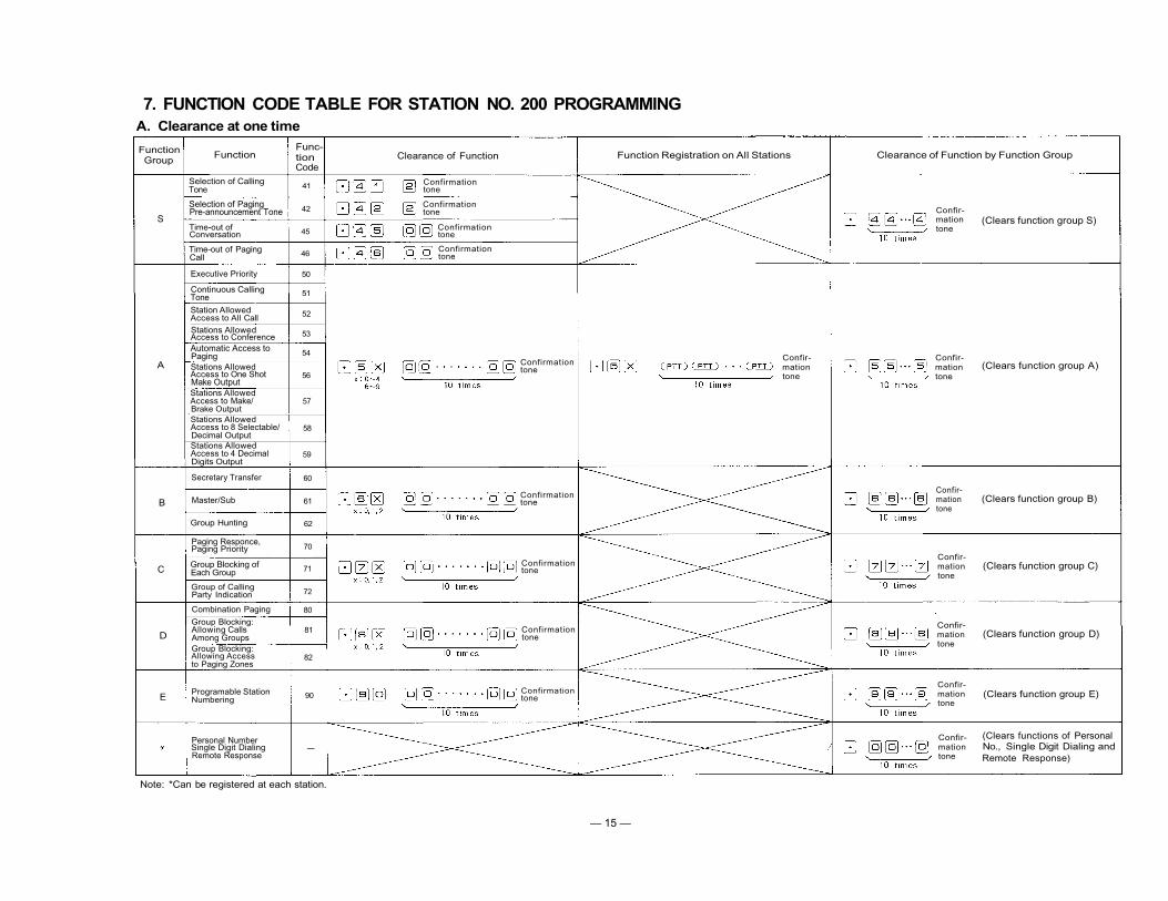
7. FUNCTION CODE TABLE FOR STATION NO. 200 PROGRAMMINGA. Clearance at one time
FunctionGroup
S
A
B
C
D
E
Function
Selection of CallingTone
Selection of PagingPre-announcement Tone
Time-out ofConversation
Time-out of PagingCall
Executive Priority
Continuous CallingTone
Station AllowedAccess to All Call
Stations AllowedAccess to ConferenceAutomatic Access toPagingStations AllowedAccess to One ShotMake OutputStations AllowedAccess to Make/Brake OutputStations AllowedAccess to 8 Selectable/Decimal OutputStations AllowedAccess to 4 DecimalDigits Output
Secretary Transfer
Master/Sub
Group Hunting
Paging Responce,Paging Priority
Group Blocking ofEach Group
Group of CallingParty Indication
Combination Paging
Group Blocking:Allowing CallsAmong GroupsGroup Blocking:Allowing Accessto Paging Zones
Programable StationNumbering
Personal NumberSingle Digit DialingRemote Response
Func-tionCode
41
42
45
46
50
51
52
53
54
56
57
58
59
60
61
62
70
71
72
80
81
82
90
-
Note: *Can be registered at each station.
Clearance of Function Function Registration on All Stations Clearance of Function by Function Group
(Clears function group S)
(Clears function group A)
Confir-mationtone
Confir-mationtone
Confir-mationtone
Confir-mationtone
(Clears function group B)
Confir-mationtone
(Clears function group C)
Confir-mationtone
(Clears function group D)
Confir-mationtone
(Clears function group E)
Confir-mationtone
(Clears functions of PersonalNo., Single Digit Dialing andRemote Response)
Confirmationtone
Confirmationtone
Confirmationtone
Confirmationtone
Confirmationtone
Confirmationtone
Confirmationtone
Confirmationtone
Confirmationtone
— 15 —

FUNCTION CODE TABLE FOR STATION NO. 200 PROGRAMMING
B. Programming of System
FunctionGroup
S
Function
Selection of Calling Tone
Selection of PagingPre-announcementTone Duration
Time-out of Conversation
Time-out of Paging Call
FunctionCode
41
42
43
44
Remarks
Two different calling tones, single note tone ortrill note tone, are available in selection forthe Hands-free system except the continuouscalling tone.
You can select the length of time of pagingpre-announcement tone.
Stations can be disconnected automaticallyfrom the speech path in the unit of Minute andthe Hurry-up Signal Tone can be heard 10seconds before the disconnection.
Stations can be disconnected automaticallyfrom the Paging circuit in the unit of Minuteand the Hurry-up Signal Tone can be heard 10seconds before the disconnection.
InitiallyProgrammed
Mode
Trill note Tone(0.3 sec.)
PagingPre-announce-ment Tone(2 sec.)
WithoutTime-out
WithoutTime-out
Operating for Programming
0: Without Calling Tone1: Single Note Tone (0.2 sec.)2: Trill note Tone (0.3 sec.)
0: Without Paging Pre-announcement Tone.1: Paging Pre-announcement Tone (1 sec.)2: Paging Pre-announcement Tone (2 sec.)
00: Without Time-out function01~99: Length limited (minute)
00: Without Time-out function01~99: Length limited (minute)
— 16 —

FUNCTION CODE TABLE FOR STATION NO. 200 PROGRAMMINGC. Programming of each Function
*1 Station No.'s except Programmed Station No.'s are Hardwired Station No.'s No.200~327/No.100~227/No.20~99/No. 10-99.*2 Programmed Station No.' s are No.200~999/No.100~999/No.20~99/No. 10-99.
3rd Parameter 4th Parameter OPERATING FOR PROGRAMMINGFunc-tionGroup
A
B
C
Function
Executive Priority
Continuous CallingTone
Station AllowedAccess to All Call
Stations AllowedAccess toConferenceAutomatic Access toPagingStations AllowedAccess to One ShotMake OutputStations AllowedAccess to Make/Break OutputStations AllowedAccessto 8 Selectable(One Shot Make)/Decimal OutputStations AllowedAccess to 4Decimal DigitsOutput
Secretary Transfer
Master/Sub
Group Hunting
Paging Zone
Group Blocking:Establishment ofEach Group
Group of CallingParty Indication
Func-tionCode
50
51
52
53
54
56
57
58
59
60
61
62
70
71
72
1st Parameter
Station No.
Station No.
Station No.
Station No.
Station No.
Station No.
Station No.
Station No.
Station No.
ExecutiveStation No.
Sub Station No.
Main station No.
Zone No. (01~15)
Group No. (1~8)
Group No. (1~8)
2nd Parameter
ON/OFF (1/0)
ON/OFF (1/0)
ON/OFF (1/0)
ON/OFF (1/0)
ON/OFF (1/0)
ON/OFF (1/0)
ON/OFF (1/0)
ON/OFF (1/0)
ON/OFF (1/0)
Secretary StationNo.
Master Station No.
Transfered StationNo.
The First StationNo. of the Zone
The First StationNo. of the Group
The First StationNo. of the Group
The Last StationNo. of the Zone
The Last StationNo. of the Group
The Last StationNo. of the Group
D
Combination Paging
Group Blocking:Allowing CallsAmong Groups
Group Blocking:Allowing Accessto Paging Zones
80
81
82
CombinationZone No. (90~99)
Calling Group No.(1~8)
Paging Zone No. ofPaged Group(00~15, 90~99)
Zone No. (s) (01 ~ 15) (Plural)
Called Group No.(s) (1~8)(Plural)
Paing Group No.(s) (1~8)(Plural)
E ProgramableStation Numbering 90
Hardwired StationNo.
*2
The FirstHardwiredStation No.
*1
Programmed Sta-tion No.
*2
The LastHardwiredStation No.
*1
The FirstProgrammedStaion No.
*2
The LastProgrammedStation No.
*2
— 17 —

8. STATION NO. 200 PROGRAMMING FOR EACH FUNCTION8-1 EXECUTIVE PRIORITY (FUNCTION CODE 50)
NOTES
1. To allow all the stations to have this function,
Touch
Be sure to depress the keys steadily.
2. To release at one time the data programmed into all thestations for this function,
Touch (Confirmation tonewill be heard.)
3. Re-start at Step 1 when mis-dialing occures.(All other registrations remain valid.)
4. Station No. should be 2 digits in length when 2 Digit Dialing
function is employed.
5. CP DIP switch B-3 must be "ON" to employ this function.
(Confirmation tonewill be heard.)
EXECUTIVE PRIORITY
STEP1
Touch
Function Code
New Registration?
Executive Station No.
Touch
ON
NO
Executive Station No. ON
Touch
NO
Confirmation tone
New Registration finished?
YES
NORelease?
YES
Executive Station No. OFF
Touch
Executive Station No. OFF
Touch
Confirmation tone
Release finished?
YES
NO
Return
— 18 —

8-2 CONTINUOUS CALLING TONE (FUNCTION CODE 51)
NOTES
1. To allow all the stations to have this function,
Touch (Confirmation tonewill be heard.)
Be sure to depress the keys steadily.
3. Re-start at Step 1 when mis-dialing occures.
(All other registrations remain valid.)
4. Station No. should be 2 digits in length when 2 Digit Dialing
function is employed.
5. CP DIP switch E-6 must be "ON" to employ this function.2. To release at one time the data programmed into all thestations for this function,
(Confirmation tonewill be heard.)
Touch
CONTINUOUS CALLING TONE
STEP1
Touch
Function Code
New Registration?NO
YES
Continuously Called Station No. ON
Touch
Continuously Called Station No. ON
Touch
Confirmation tone
NONew Registration finished?
NORelease?
YES
Continuously Called Station No. OFF
Touch
Continuously Called Station No. OFF
Touch
Confirmation tone
Release finished?
YES
Return
NO
— 19 —

8-3 STATIONS ALLOWED ACCESS TO ALL CALL (FUNCTION CODE 52)
NOTES
1. To allow all the stations to have this function,
Touch(Confirmation tonewill be heard.)
3. Re-start at Step 1 when mis-dialing occures.(All other registrations remain valid.)
4. Station No. should be 2 digits in length when 2 Digit Dialing
function is employed.
5. Programming is necessary only if CP DIP switch D-1 is "ON".
Be sure to depress the keys steadily.
2. To release at one time the data programmed into all thestations for this function,
Touch (Confirmation tonewill be heard.)
STATIONS ALLOWED ACCESS TO ALL CALL
STEP1
Touch
Function Code
New Registration?NO
YES
Allowed Station No. ON
Touch
Touch
Allowed Station No. ON
Confirmation tone
New Registration finished?NO
YES
Release? NO
YES
Allowed Station No. OFF
Touch
Allowed Station No. OFF
Touch
Confirmation tone
Release finished?
YES
Return
NO
— 20 —

NOTES
1. To allow all the stations to have this function,
Touch(Confirmation tonewill be heard.)
Be sure to depress the keys steadily.
2. To release at one time the data programmed into all thestations for this function,
Touch (Confirmation tonewill be heard.)
3. Re-start at Step 1 when mis-dialing occures.(All other registrations remain valid.)
4. Station No. should be 2 digits in length when 2 Digit Dialing
function is employed.
5. Programming is necessary only if CP DIP switch D-1 is "ON".Switch B-1 must be "ON" to employ this function.
8-4 STATIONS ALLOWED ACCESS TO CONFERENCE (FUNCTION CODE 53)
STATIONS ALLOWED ACCESS TO CONFERENCE
STEP 1
Touch
NO
Allowed Station No. ON
Touch
Allowed Station No. ON
Touch
Confirmation tone
NO New Registration finished?
YES
NORelease?
YES
Allowed Station No. OFF
Touch
Allowed Station No. OFF
Touch
Confirmation tone
Release finished?NO
Return
YES
— 21 —

8-5 AUTOMATIC ACCESS TO PAGING (FUNCTION CODE 54)
NOTES
1. To allow all the stations to have this function,
Touch (Confirmation tonewill be heard.)
3. Re-start at Step 1 when mis-dialing occures.
(All other registrations remain valid.)
4. Station No. should be 2 digits in length when 2 Digit Dialing
function is employed.Be sure to depress the keys steadily.
2. To release at one time the data programmed into all thestations for this function.
Touch (Confirmation tonewill be heard.)
HANDSET SUBSTATIONS ALLOWED ACCESS TO PAGING
STEP 1
Touch
Function Code
New Registration?NO
YES
Allowed Station No. ON
Touch
Allowed Station No. ON
Touch
Confirmation tone
NO New Registration finished?
YES
NORelease?
YES
Allowed Station No. OFF
Touch
Allowed Station No. OFF
Touch
Confirmation tone
Release finished?
YES
Return
NO
— 22 —

Note. Possible
Impossible
Possible but usually Not to be used
(5) Call by Dialing & Picking up the Handset
COMPLEMENTARY NOTES
(1) Automatic Access to PagingThis function facilitates Paging / Paging response from aSubstation TL-600S. Just picking up the Handset of Sub-station automatically activates Paging or Paging Responsemode.
(2) Required Programming for Automatic Access to Pagingfrom Handset Substation.
2-1) First, connect a Master Station HF-600M or TL-600M in placeof a Substation TL-600S.
2-2) Program at that station a necessary function for Single DigitDialing such as Paging, Paging Response, Personal Number Callor etc.
2-3) Then, replace the Master Station with a Substation TL-600S.2-4) Program "Automatic Access to Paging from Handset Substation
(Function Code 54)" at the Station No. 200 according to theprogramming instructions.
(3) Single Digit Dialing and Automatic Access to PagingBy programming "Single Digit Dialing" at any master station, asingle touch of the dial activates "Station Call", "PersonalNumber Call", "Paging" or "Paging Response" mode. But inusing a TL-600S and a HF-600S, "Automatic Access to Pagingfrom Handset Substation" function cannot be adopted only byprogramming "Single Digit Dialing" at the station. It alsoreqires the programming for Function Code 54 at No. 200Station.
(4) A call to Master Station from Handset or Hands-free/Handset Substation"Master/Sub Relationship (Function Code 61)" can beprogrammed into Handset Substation TL-600S or Hands-free/
Handset Substation HF-600S etc., where you can call therelative Master Station by a single touch of the dial , or bypicking up the Handset.In activating a mode with Hands-free/Handset SubstationHF-600S by picking up the Handset, "Privacy" switch on theStation is to be "ON" position.
Function
Single Digit
Dialing
Master/sub
Relationship
Automatic Acess to Paging
Paging (or Calling)
from Handset Substation
NecessaryProgramming
Single Digit
Registration
at Station
Programming at
Station No. 200
(Function Code 61)
1. Single Digit
Registration
at Station
2. Programming at
Station No.200
(Function Code 54)
Call to Master Station
By dialing
atHF-620S or
HF-600S
By picking upHandset
atTL-600S or
HF-600S(Privacy SW. ON)
Paging Call, Paging Responseor Personal Number Call
By dialing
atHF-620S or
HF-600S
By picking upHandset
atTL-600S or
HF-600S
(Privacy SW. ON)
— 23 —

3. Re-start at Step 1 when mis-dialing occures.(All other registrations remain valid.)
4. Station No. should be 2 digits in length when 2 Digit Dialing
function is employed.
5. Programming is necessary only if CP DIP switch D-1 is "ON".
NOTES
1. To allow all the stations to have this function,
Touch (Confirmation tonewill be heard.)
Be sure to depress the keys steadily.
2. To release at one time the data programmed into all thestations for this function,
Touch (Confirmation tonewill be heard.)
8-6 STATIONS ALLOWED ACCESS TO ONE-SHOT MAKE OUTPUT (FUNCTION CODE 56)
STATION ALLOWED ACCESS TO ONE SHOT MAKE OUTPUT
STEP1
New Registration?NO
Function Code
YES
Allowed Station No. ON
Touch
Allowed Station No. ON
Touch
Confirmation tone
NO New Registration finished?
YES
NORelease?
YES
Allowed Station No. OFF
Touch
Allowed Station No. OFF
Touch
Confirmation tone
Release finished?NO
YES
Return
— 24 —

3. Re-start at Step 1 when mis-dialing occures.{All other registrations remain valid.)
4. Station No. should be 2 digits in length when 2 Digit Dialing
function is employed.
5. Programming is necessary only if CP DIP switch D-1 is "ON".
NOTES
1. To allow all the stations to have this function,
Touch (Confirmation tonewill be heard.)
Be sure to depress the keys steadily.
2. To release at one time the data programmed into all thestations for this function,
Touch (Confirmation tonewill be heard.)
8-7 STATIONS ALLOWED ACCESS TO MAKE/BREAK OUTPUT (FUNCTION CODE 57)
STATIONS ALLOWED ACCESS TO MAKE/BREAK OUTPUT
STEP 1
Touch
Function Code
New Registration?NO
YES
Allowed Station No. ON
Touch
Allowed Station No. ON
Touch
Confirmation tone
NO New Registration finished?
Release? NO
Allowed Station No. OFF
Touch
Allowed Station No. OFF
Touch
Confirmation tone
Release finished?
Return
YES
NO
— 25 —

3. Re-start at Step 1 when mis-dialing occures.(All other registrations remain valid.)
4. Station No. should be 2 digits in length when 2 Digit Dialing
function is employed.
5. Programming is necessary only if CP DIP switch D-1 is "ON".
NOTES
1. To allow all the stations to have this function,
Touch (Confirmation tonewill be heard.)
Be sure to depress the keys steadily.
2. To release at one time the data programmed into all thestations for this function,
Touch (Confirmation tonewill be heard.)
8-8 STATIONS ALLOWED ACCESS TO 8 SELECTABLE (ONE-SHOT MAKE) OR DECIMAL OUTPUT(FUNCTION CODE 58)
STATIONS ALLOWED ACCESS TO 8 SELECTABLE(ONE-SHOT MAKE) OR DECIMAL OUTPUT
STEP1
Touch
Function Code
New Registration?NO
Allowed Station No. ON
Touch
Allowed Station No. ON
Touch
Confirmation tone
New Registration finished?
YES
Release? NO
Allowed Station No. OFF
Touch
Allowed Station No. OFF
Touch
Confirmation tone
Release finished?NO
Return
— 26 —

8-9 STATIONS ALLOWED ACCESS TO 4 DECIMAL DIGITS OUTPUT (FUNCTION CODE 59)
NOTES
1. To allow all the stations to have this function, 3. Re-start at Step 1 when mis-dialing occures.(All other registrations remain valid.)
4. Station No. should be 2 digits in length when 2 Digit Dialing
function is employed.
5. Programming is necessary only if CP DIP switch D-1 is "ON".2. To release at one time the data programmed into all thestations for this function,
Touch(Confirmation tonewill be heard.)
Touch (Confirmation tonewill be heard.)
STATIONS ALLOWED ACCESS TO 4 DECIMAL DIGITS OUTPUT
STEP 1
Touch
Function Code
New Registration?
Allowed Station No. ON
Touch
Touch
Allowed Station No. ON
Confirmation tone
New Registration finished?
Release?
Allowed Station No. OFF
Touch
Allowed Station No. OFF
Touch
Confirmation tone
Release finished?
Return
NO
YES
NO
YES
NO
YES
NO
YES
Be sure to depress the keys steadily.
— 27 —

NOTES
1. To release at one time the data programmed into all thestations for this function,
3. Station No. should be 2 digits in length when 2 Digit Dialingfunction is employed.
4. Switch B-5 must be "ON" to employ this function.
5. Programming of Secretary Transfer can be made in a daisychain method. For their examples, refer to the following sketch.
Touch (Confirmation tonewill be heard.)
2. Re-start at Step 1 when mis-dialing occurs.(All other registrations remain valid.)
8-10 SECRETARY TRANSFER (FUNCTION CODE 60)
SECRETARY TRANSFER
Step 1
Touch
Function Code
New Registration?
Executive Station No. Secretary Station No.
Touch
Executive Station No.
Touch
Secretary Station No.
Confirmation tone
New Registration finished?
Release?
Executive Station No. Executive Station No.
Touch
Executive Station No. Executive Station No.
Touch
Confirmation tone
Release finished?
Return
— 28 —

8-11 MASTER/SUB RELATIONSHIP (FUNCTION CODE 61)
NOTES
1. To release at one time the data programmed into all thestations for this function,
3. Station No. should be 2 digits in length when 2 Digit Dialingfunction is employed.
Touch (Confirmation tonewill be heard.)
2. Re-start at Step 1 when mis-dialing occurs.(All other registrations remain valid.)
MASTER/SUB RELATIONSHIP
Step 1
Touch
Function Code
New Registration?NO
YES
Sub Station No. Master Station No.
Touch
Sub Station No. Master Station No.
Touch
Confirmation tone
NONew Registration finished?
YES
NORelease?
YES
Sub Station No. Sub Station No.
Sub Station No. Sub Station No.
Touch
Touch
Confirmation tone
NORelease finished?
Return
— 29 —

NOTES
1. To release at one time the data programmed into all thestations for this function,
Touch (Confirmation tonewill be heard.)
2. Re-start at Step 1 when mis-dialing occurs.(All other registrations remain valid.)
3. Station No. should be 2 digits in length when 2 Digit Dialingfunction is employed.
4. Switch B-5 must be "ON" to employ this function.
5. Programming of Group Hunting can be made in a daisy chainmethod. For their examples, refer to the following sketch.
8-12 GROUP HUNTING (FUNCTION CODE 62)
TRANSFERED STATION No. FOR GROUP HUNTING
Step 1
Touch
Function Code
New Registration?
Original Station No. Transfered Station No.
Touch
Touch
Original Station No. Transfered Station No.
Confirmation tone
New Registration finished?NO
Release?
Original Station No. Original Station No.
Original Station No. Original Station No.
Touch
Confirmation tone
Release finished?
Return
— 30 —

8-13 PAGING ZONE (FUNCTION CODE 70)
NOTES
1. To release at one time the data programmed into all theZones for this function,
Touch (Confirmation tonewill be heard.)
2. Re-start at Step 1 when mis-dialing occurs.(All other registrations remain valid.)
3. Station No. should be 2 digits in length when 2 Digit Dialing
function is employed.
4. Switch B-4 must be "ON" to employ this function.
5. 2-Digit dialing is necessary even in the case of Zone No. 1
to No. 7.
Ex. Zone No.2
6. In the case "Paging Response Without Zone Number" modeis selected by the DIP Switch SW-E-2, this
registration is essential.
7. In the case "Paging Priority" function is adopted by the DIP
Switch SW-C-3, this registration should be made for eachPaging Zone of No. 01 to No. 07.
ESTABLISHMENT OF EACH PAGING ZONE
Step 1
Touch
Function Code
Paging Zone No.(01 ~ 15)
1st Station No.of the Zone
Last Station No.of the Zone
Touch
Paging Zone No.(01 ~ 15)
1st Station No.of the Zone
Last Station No.of the Zone
Touch
Confirmation tone
New Registration finished?
Return
— 31 —

NOTES
1. To release at one time the data programmed into all thegroups for this function,
Touch (Confirmation tonewill be heard.)
3. Station No. should be 2 digits in length when 2 Digit Dialingfunction is employed.
4. CP DIP switch D-4 must be "ON" to employ this function.
2. Re-start at Step 1 when mis-dialing occurs.(All other registrations remain valid.)
8-14 GROUP BLOCKING 1 : ESTABLISHMENT OF EACH GROUP (FUNCTION CODE 71)
GROUP BLOCKING 1
ESTABLISHMENT OF EACH GROUP
Step 1
Touch
Function Code
Group No. 1st Station No. Last Station No.(1~8) of the Zone of the Zone
Touch
Group No. 1st Station No. Last Station No.(1~8) of the Zone of the Zone
Touch
Confirmation tone
New Registration finished?NO
Return
— 32 —

8-15 CALLING PARTY INDICATION (LAMP TYPE) (FUNCTION CODE 72)
NOTES
1. To release at one time the data programmed into all thegroups for this function,
Touch (Confirmation tonewill be heard.)
3. Station No. should be 2 digits in length when 2 Digit Dialingfunction is employed.
4. When the Indication Panel belongs to only one (1) station,you should write the station number in both "First StationNo." and "Last Station No." columns.
2. Re-start at Step 1 when mis-dialing occurs.
(All other registrations remain valid.)
ESTABLISHMENT OF EACH GROUP
Step 1
Touch
Function Code
Group No. 1st Station No. Last Station No.(1 ~ 8) of the Zone of the Zone
Touch
Group No. 1st Station No. Last Station No.(1 ~ 8) of the Zone of the Zone
Touch
Confirmation tone
NONew Registration finished?
Return
— 33 —

NOTES
1. To release at one time the data programmed into all theZones for this function,
3. CP DIP switch B-4 and C-4 must be "ON" to employ thisfunction.
2. Re-start at Step 1 when mis-dialing occurs.(All other registrations remain valid.)
(Confirmation tonewill be heard.)
Touch
8-16 COMBINATION PAGING (FUNCTION CODE 80)
COMBINATION PAGING
Step 1
Touch
Function Code
New Registration?
Combination Paging Paging Zone No. (s)Zone No. (90 ~ 99) (01 ~ 15) (01 ~ 15)
Touch
Touch
Combination Paging Paging Zone No. (s)Zone No. (90 ~ 99) (01 ~ 15) (01 ~ 15)
Confirmation tone
New Registration finished?
Release?
Combination Paging Zone No. (90 ~ 99)
Touch
Combination Paging Zone No. (90 ~ 99)
Touch
Confirmation tone
Release finished?
Return
— 34 —

8-17 GROUP BLOCKING 2 : ALLOWING CALLS AMONG GROUPS (FUNCTION CODE 81)
GROUP BLOCKING 2
NOTES
1. To release at one time the data programmed into all the
groups for this function,
Touch (Confirmation tonewill be heard.)
2. Re-start at Step 1 when mis-dialing occurs(All other registrations remain valid.)
3. Do not register a Group to call itself.
4. CP DIP switch D-4 must be "ON" to employ this function.
ALLOWING CALLS AMONG GROUPS
Step 1
Touch
Function Code
New Registration?
Calling Group Called GroupNo. (1 ~ 8) No. (s) (1 ~ 8) (max. 7)
Touch
Calling Group Called GroupNo. (1 ~ 8) No. (s) (1 ~ 8} (max. 7)
Touch
Confirmation tone
New Registration finished?
Release?
Calling Group No. (1 ~ 8)
Touch
Calling Group No. (1 ~ 8)
Touch
Confirmation tone
Release finished?NO
YES
Return
— 35 —

8-18 GROUP BLOCKING 3 : ALLOWING GROUP ACCESS TO PAGING (FUNCTION CODE 82)
GROUP BLOCKING 3
NOTES
1. To release at one time the data programmed into all the
groups for this function,
Touch (Confirmation tonewill be heard.)
2. Re-start at Step 1 when mis-dialing occurs
(All other registrations remain valid.)
3. CP DIP switch D-4 must be "ON" to employ this function.
ALLOWING ACCESS TO PAGING ZONES
Step 1
Touch
Function Code
New Registration?
Paging Zone (00 ~ 15) or Paging Group No. (S)Combination Paging Zone (90 ~ 99) (1 ~ 8) (max. 8)
Touch
Paging Zone (00 ~ 15) or Paging Group No. (S)Combination Paging Zone (90 ~ 99) (1 ~ 8) (max. 8)
Touch
Confirmation tone
New Registration finished?
Release?
Paging Zone (00 ~ 15) orCombination Paging Zone (90 ~ 99)
Touch
Paging Zone (00 ~ 15) orCombination Paging Zone (90 ~ 99)
Touch
Confirmation tone
Release finished?
Return
— 36 —

NOTES
1. To release all registered Programmed Station No.'s at one time,
Touch (Confirmation tonewill be heard.)
2. Re-start at Step 1 when mis-dialing occurs.(All other registrations remain valid.)
3. Any one Programmed Station No. cannot be assigned to more
than one Hardwired Station.
4. CP DIP switch D-5 must be "ON" to employ this function.
8-19 PROGRAMMABLE STATION NUMBERING (FUNCTION CODE 90)
A. Programming of Single Station Number
PROGRAMMABLE STATION NUMBERING
Step 1
Touch
Function Code
New Registration?
Hardwired Station No. Programmed Station No.
Touch
Hardwired Station No. Programmed Station No.
Touch
Confirmation tone
New Registration finished?
Release?
Hardwired Station No. Hardwired Station No.
Touch
Hardwired Station No. Hardwired Station No.
Touch
Confirmation tone
Release finished?
Return
— 37 —

PROGRAMMABLE STATION NUMBERING (FUNCTION CODE 90)
B. Programming of Serial Station Numbers
NOTES
1. To release all registered Programmed Station No.'s at one time,
Touch (Confirmation tonewill be heard.)
2. Re-start at Step 1 when mis-dialing occurs.
(All other registrations remain valid.)
3. Any one Programmed Station No. cannot be assigned to more
than one Hardwired Station.
4. CP DIP switch D-5 must be "ON" to employ this function.
PROGRAMMABLE STATION NUMBERING
Step 1
Touch
Function Code
New Registration?
First Last First LastHardwired Station No. Hardwired Station No. Programmed Station No. Programmed Station No.
First Last First LastHardwired Station No. Hardwired Station No. Programmed Station No. Programmed Station No.
Confirmation tone
New Registration finished?
Release?
First Last First LastHardwired Station No. Hardwired Station No. Hardwired Station No. Hardwired Station No.
First Last First LastHardwired Station No. Hardwired Station No. Hardwired Station No. Hardwired Station No.
Confirmation tone
Release finished?
Return
— 38 —

9. PROGRAMMING DATA TABLE
< PROGRAMMING DATA TABLE 1 >
Function Table for the System
FunctionGroup
S
Function
Selection ofCalling Tone
Selection ofPagingPre-announcementTone
Time-out ofconversation
Time-out ofPaging call
FunctionCode
41
42
45
46
RegisteredDeta
Note of Registration
0: Without Calling Tone1: Single note tone (0.2 sec.)2: Trill note tone (0.3 sec.)
0: Without Paging Pre-announcementTone
1: Paging Pre-announcement Tone(1 sec.)
2: Paging Pre-announcement Tone(2 sec.)
00: Without Time-out function01~99: Length limited (min.)
00: Without Time-out function01~99: Length limited (min.)
Initial Programming
2:Trill note Tone(0.3 sec.)
2:PagingPre-announcementTone (2 sec.)
00:Without Time-out
00:Without Time-out
— 39 —

*1: Hardw
ired Station N
o. *2: P
rogramm
ed Station N
o.
< PR
OG
RA
MM
ING
D
ATA
TAB
LE 2>
Function Table for S
tations (1)
Executive Priority
Continuous Calling Tone
Stations Allowed Accessto All Call
Stations Allowed Accessto Conference
Automatic Access to Paging
Stations Allowed Accessto One Shot Output
Stations Allowed Accessto Make/Break Output
Stations Allowed Access to 1/8Select (or Decimal) Output
Stations Allowed Access to 4Decimal Digits Output
SecretaryStation No. *1
MasterStation No. *1
TransferedStation No. for Group Hunting *1
Paging Zone No.
Group No. for Group Blocking
Group No. forCalling Party Indication
Programmed Station No.
Function
Gro
up
AB
CE
Functio
n
Function
Code
Hardw
iredS
tatio
n N
o.
Nam
eW
ithP
ersonal No.
Without
Personal N
o.
— 40 —

<PR
OG
RA
MM
ING
D
ATA
TAB
LE 3>
Function Table fo
r Stations (2)
*1: Hardw
ired S
tation N
o. *2: P
rogramm
ed S
tation
No.
Executive Priority
Continuous Calling Tone
Stations Allowed Accessto All Call
Stations Allowed Accessto Conference
A
Automatic Access to Paging
Stations Allowed Accessto One Shot Output
Stations Allowed Accessto Make/Break Output
Stations Allowed Access to 1/8Select (or Decimal) Output
Stations Allowed Access to 4Decimal Digits Output
SecretaryStation No. *1
BMasterStation No. *1
TransferedStation No. for Group Hunting *1
Paging Zone No.
Group No. for Group Blocking
Group No. forCalling Party Indication
E
Programmed Station No.
Function G
roup
Functio
n
Functio
n C
ode
Hardw
iredS
tatio
n N
o.
Nam
e
— 41 —

*1: H
ard
wire
d S
tatio
n N
o.
*2: P
rog
ramm
ed S
tatio
n N
o.
<PR
OG
RA
MM
ING
D
ATA
TAB
LE 4>
Function Table fo
r Stations (3)
Function
Gro
up
Function
Function C
ode
Hardw
iredS
tatio
n N
o.
Nam
e
Executive Priority
Continuous Calling Tone
Stations Allowed Accessto All Call
Stations Allowed Accessto Conference
A
Automatic Access to Paging
Stations Allowed Accessto One Shot Output
Stations Allowed Accessto Make/Break Output
Stations Allowed Access to 1/8Select (or Decimal) Output
Stations Allowed Access to 4Decimal Digits Output
SecretaryStation No. *1
BMasterStation No. *1
TransferedStation No. for Group Hunting *1
Paging Zone No.
Group No. for Group Blocking
Group No. forCalling Party Indication
E
Programmed Station No.
— 42 —

<PROGRAMMING DATA TABLE 5>Paging Priority and/or Paging Response Table
Station Paging Zone
Department No.First Station No. Last Station No.
Funct
ion
Cod
e 70
For
Pag
ing
Prio
rity
For
Pag
ing
Res
pons
e
Combination Paging Table
SelectedPaging Zone
CombinationPaging Zone D
epar
tmen
t
Funct
ion
Cod
e 80
Station Numbers Table for Calling Party Indication(Lamp Type)
Note. When the indication panel belongs to only one (1) station, you should write the station numberin both "First Station No." and "Last Station No." columns.
Calling Party Indication
Name Group No.First Station No. Last Station No.
Funct
ion
Cod
e 72
— 43 —
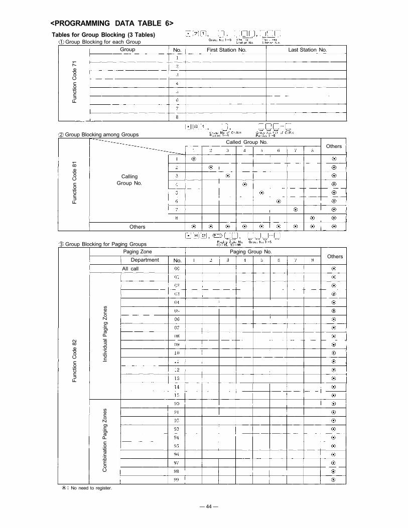
<PROGRAMMING DATA TABLE 6>Tables for Group Blocking (3 Tables)
Group Blocking for each Group
Group Blocking among Groups
Group Blocking for Paging Groups
No need to register.
CallingGroup No.
Paging Zone
Department
All call
Others
Funct
ion
Cod
e 82
Indi
vidu
al P
agin
g Z
ones
Com
bina
tion
Pag
ing
Zone
s
Funct
ion
Cod
e 81
Funct
ion
Cod
e 71
Group No. First Station No. Last Station No.
Called Group No.Others
No.
Paging Group No.Others
— 44 —

Summary Table ofGroup Blocking (Function Code 71, 81, 82),Paging Zone (Function Code 70) andCombination Paging (Function Code 80).
indicates that registration is not necessary,
indicates stations not belonging to any group.
Note:
StationsinEach Group
Calling (Paging)Group No.
Called(Paged andResponding)Group No.
Stations inEach
PagingZone
Dial Operationof Paging Call
7 IndividualPaging Zones
15 IndivisualPaging Zones
Paging Zone
Type of Paging
Paging Priority
Dial Operationof Paging Response
All Call Paging
Station Paging or PA Paging
Possible Only in Zone No. 1~7
Indivisual Zone Paging
Station Paging or PA Paging
Possible
PA Paging
Impossible
Combination Paging
Station Paging or PA Paging
Possible Only in Indivisual Zone No.1~7
Stationsnot belongingto any Zone
Paging Response
Combination Paging Zone
Stations belonging toEach Indivisual Zone
— 45 —

PART 2. FUNCTION SELECTION FOR DATATRANSMITTING AND RECEIVING UNITS
10. SETTING OF CHANNEL SELECT SWITCH OF TRANSMITTING UNIT (DT-E11) ANDWORD SELECT SWITCH OF RECEIVING UNIT (DR-B61)
NOTE1. Connect the DT-E11 and DR-B61 to Exchange correctly. (Refer
to operation manuals of DT-E11 and DR-B61).2. Set the function select switches (DIP SWITCH) on CP-62 cor-
rectly and be sure to enter initial programming and functionregistration at programming station No.200.
3. Remove the front panel of Data Transmitting Unit (DT-E11) andtake out the printed circuit board. Then set the channel selectswitches located on the printed circuit board, according to the
necessary functions such as IN/OUT Annunciation, Calling PartyIndication etc,and replace in the Unit.(Refer to 13. Explanation of Data Transmitting Unit OutputChannels, Page 50).
4. The DT-E11 sends out 512 bit data (16 bit x 32 words) tocontrol relays on Data Receiving Unit (DR-B61). Therefore setthe two word select switches on DR-B61, according to necessaryoutput mode. SW-1 is for Relay No.1 to No.16 and SW-2 is forRelay No.17 to No.32. See Page 51 fordatails.(Refer to Explanation of Date Receiving Unit Output Channels.)
5. Connecting Cable YR-802 is used for the Rack mounting system.Connecting Cable YR-806 is used for the Standard Cabinetmounting system with only One (1) DT-E11 unit.
CHANNEL SELECTSwitch (SW-1)
To other RD-B61WORD SELECT Switch
(SW-1, SW-2)
To otherDT-E11
One Pair Cable
ConnectingCable YR-803
To other DR-B61
ConnectingCable YR-802or YR-806
— 46 —

Note shows the Head of a Slide Switch WORD SELECT Switch
CHANNEL SELECT Switch
11. DIP SWITCH TABLE FOR DATA TRANSMITTING AND RECEIVING UNITS
Data Receiver Relay Output No.
Exchange
Data Transmitter
Eac
h ch
anne
l outp
ut
of
DT
-E11
may
be
con
ne
cte
d to
DR
-B6
1 (
s) (
as a
bove
fo
r C
H.0
)
— 47 —

Calling Party DisplayBoard.Indication by decimaldigits.
Calling Party DisplayBoard.1 Station 1 -lampIndication.8 stations(8 groups)
DestinationIndicationStation No.No. 201~232
a. Conference Room,b. Reception Room,Room Condition Indication,Destination Indication, etc.
Room Condition Indication,Destination Indication.
Called Party withIndicatorNo. 201~216
Called Party withIndicatorNo. 217 ~ 232
Called Party withIndicator4 stations (4 groups)
Called Party withIndicator4 stations (4 groups)
Personal No.No. 1000~1015
Personal No.No. 1016~1031
Prescription DisplayBoard, etc.
a. President,b. Department Chief,Room Condition Indication,Destination Indication, etc.
Prescription DisplayBoard, etc.
In/Out AnnunciationDisplay Board
(Data Receiver(Equipment using DR-B61)
YR-802or
YR-806
YR-803
YR-803
YR-803
YR-803
YR-803
YR-803
YR-803
YR-803
YR-803
YR-803
YR-803
(1) 4 Decimal Digits Output (9 Units)(2) Decimal Output (9 Units)(3) 8 Selectable Make Output (9 Units)(4) Pager Control (100 contacts)(5) 8 selectable One-shot Make Output
(9 Units)
Destination Indication (2)
Destination Indication (1)
Calling Party Indication.Lamp Type (2)
Calling Party Indication.Lamp Type (1)
Calling Party Indication.Numerical Type (2)
Calling Party Indication.Numerical Type (1)
8 Selectable Make Output(64 Units)
Decimal Output (99 Units)
One-shot-Make Output(500/50 contacts)
Make-Break Output(51 2/1 00 contacts)
In/Out Annunciations(500 contacts)
Data Transmitting Unit
Two wires
Exchange
YR-810
c. Section Chief,d. Chief Clerk
Stations
c. Outd. Waiting Room
12. SYSTEM DIAGRAM OF DATA TRANSMITTING AND RECEIVING UNITS
— 48 —

YR-802or
YR-806
YR-803
YR-803
YR-803
Calling Party Indication.Lamp Type. (1)1 -station = 1 -lam p indication.
Calling Party Indication.Lamp Type. (2)1 -station= 1 -lamp indication.
Calling Party Indication.Numerical Type. (2)
Calling Party Indication.Numerical Type. (1)
Enlarged Block Diagram of Calling Party Indication
Station numbers of
Called Parties with Indicator
16 units
16 units
4 units
4 units
(Calling Party Display Panel with DR-B61)
Two wires
Data Transmitting Unit
Exchange
— 49 —

IN/OUT Annunciation(500 persons)
Make/Break Output(512/100 contacts)
One-shot Make Output(500/50 contacts)
(1) 4 Decimal digits output(9 units)
(2) Decimal Output(9 units)
(3) 8 Selectable Make Output.(9 units)
(4) Pager Control Output(100 pagers)
(5) 8 Selectable One-shotMake Output (9 unit)
Decimal Output(99 units)
8 selectable make Output(64 units)
Calling Party IndicationNumerical-type (1)
Calling Party IndicationNumerical-type (2)
Calling Party Indication(One Station; One Lamp)
Calling Party Indication(One Station; One Lamp)
DestinationIndication (1)
DestinationIndication (2)
Personal in and out registration canbe accomplished at any Masterstation by using personal numbersMax. 500 IN/OUT annunciationsmay be done.
Make/Break contacts can be availableat any Master station.
One-shot make contacts can beavailable at any Master station.
Indicate by 7 segments LEDs.
10 Selectable Decimal Outputs areavailable with 7 segments LEDs.
One contact out of 8 selectable makeoutputs is obtained. "Clear" ope-ration makes all 8 relays break.
Make output (100 contacts)available for pager control.
One contact out of 8 selectable makeoutputs is obtained for about 1or 2 seconds.
10 Selectable Decimal Outputs areavailable with 7 segments LEDs.
One contact out of 8 selectable makeoutputs is obtained. "Clear" ope-ration makes all 8 relays break.
When a station with a Display Boardis called, calling party number isindicated until the conversation isover and also when the called stationis busy or in privary.
Max. 128 Calling station numbers canbe indicated when designated calledstation with Display Board is called.The numbers of called stations havingan indication panel can be program-med at No.200 station.
When a person makes his ownPersonal Number Programming at thestation, the station number at whichthe registration was made can beindicated by the lamp.
• IN/OUT Annunciation
• Door Remote• IN/OUT Annunciation
• ITV camera select• VTR control
• Prescription annunciation
• Room condition indication
• Destination indication
• Pager
• VTR control
• Room condition indication• Destination indication
• Room condition indication• Destination indication
• The number of called stationsare No.201~No.216.
• The number of called stationsare No.217~No.232.
• The group number of calledstation(s). No.1~4
• The group number of calledstation(s). No.5-8
• Personal number No.1000~ 1015
• Personal number No.1016~1032
13. EXPLANATION OF DATA TRANSMITTING UNIT OUTPUT CHANNELS
— 50 —
CHANNEL SELECTION FUNCTIONS DESCRIPTION APPLICATION

14. EXPLANATION OF DATA RECEIVING UNIT OUTPUT CHANNELS14-1 Channel 0 (CH. 0) In/Out Annunciation
(Dial Operation)Personal Number Registration
Personal Number Cancellation
CHANNEL SELECT Switch
Data Transmitter
Exchange
Date Receiver Relay Output No.
WORD SELECT SwitchNote shows the Head of a Slide Switch
Each Relay Output showslast 3 digits (xxx) of PersonalNumber
— 51 —

14-2 Channel 1 (CH. 1) Make/Break Output
CHANNEL SELECT Switch
Each Relay Output showsRelay Contact Number.
WORD SELECT SwitchNote shows the Head of a Slide Switch
Exchange
Data TransmitterData Receiver Relay Output No.
(Dial Operation)
— 52 —

Each Relay Output showsRElay Contact Number.
14-3 Channel 2 (CH. 2) One-Shot Make Output
Exchange
Data Transmitter
CHANNEL SELECT Switch
Note shows the Head of a Slide Switch WORD SELECT Switch
Relay Output No.Data Receiver
(Dial Operation)
— 53 —

14-4 Channel 3 (CH. 3)Exchange
(1) 4 Decimal Digits Output (9 units)(3) 8-Selectable Make Output (9 units)(5) 8-Selectable One-shot Make Output
(9 units)
(2) Decimal Output (9 units)(4) Pager Control Output (100 contacts)
CHNNEL SELECT Switch
(Example)(1) 4 Decimal Digits Output
Binary Output Negative Logic
(2) Decimal Output
(3) 8-Selectable Make Output
Each Relay Output showsRelay Contact Number.
Unit No.4 Condition "1"
Unit No.6 Condition "8"
(5) 8-Selectable One-shot MakeOutput
Pager No.79 is being called.
(4) Pager Control Output
Bindary NegativeLogic Output
Unit No.4 Condition"!"
Unit No.6 Condition "8"
1: Relay Make0: Relay Break
Unit No.8 Condition "9"
Note shows the Head of a Slide SwitchWORD SELECT Switch
Display8-Select.Decimal
Data Receiver
Data Transmitter
Relay Output No.
(1)
4 D
ecim
al D
igits
Outp
ut
[9 U
nits
](2
) D
ecim
alO
utp
ut
[9 U
nits
]
(3)
8-S
elec
tabl
eM
ake
Outp
ut
[9 U
nits
]
(4)
Pag
er C
on
tro
l O
utp
ut
[100
C
on
tact
s](5
) 8-
Sel
ecta
ble
One
-sho
t M
ake
Ou
tpu
t[9
Un
its]
— 54 —

1: Relay Make0: Relay Break
Note shows the Head of a Slide Switch WORD SELECT Switch
14-5 Channel 4 (CH. 4) Decimal Output (99 Units)
Unit No.48 Condition"0"
Binary Negative Logic "0"
(Example)
Unit No.24 Condition "3"
Binary Negative Logic "3"
CHANNEL SELECT Switch
Data Transmitter
Exchange(Dial Operation)
Data Receiver Relay Output No.
— 55 —

Note shows the Head of a Slide SwitchWORD SELECT Switch
Relay Output No.Data Receiver
(Dial Operation)
14-6 Channel 5 (CH. 5) 8-Selectable Make Output (64 Units)
Exchange
Data Transmitter
CHNNEL SELECT Switch
(Example)
Unit No.8 Condition "1"
Unit No.10 Condition "8"
1: Relay Make0: Relay Break
— 56 —

14-7 Channel 6 (CH. 6) Calling Party Indication Numerical Type (1)
7 Segments Display of "Calling Station No.", "Waiting Station No." and "Total Number of WaitingStations". Total Number of Station with Indications, 16 stations/Channel (32 stations/2 Channel)
Data Receiver Relay Output No.Station No.with Indication
No.201
No.202
No.203
No.204
No .205
No.206
No.207
No .208
No.209
No.210
No.211
No.212
No.213
No.214
No.215
No.216
d.c.:d.w.:t.n.w.:
—logic:1:0:
Digit of Calling Station No.Digit of Waiting Station No.Total Number of WaitingStations.Binary negative logicRelay MakeRelay Break
Station No.207Lamp "ON" Condition
(Example)
Station No.205Lamp "OFF" Condition
Exchange
Data Transmitter
CHANNEL SELECT Switch
NoteWORD SELECT Switch
shows the Head of a Slide Switch
— 57 —

14-8 Channel 7 (CH. 7) Calling Party Indication Numerical Type (2)
Exchange 7 Segments Display of "Calling Station No.", "Waiting Station No." and "Total Number of WaitingStations". Total Number of Station with Indications, 16 stations/Channel (32 stations/2 Channel)
Data Transmitter
CHANNEL SELECT Switch
Data Receiver Relay Output No.Station No.with Indication
No.217
No.218
No.219
No.220
No.221
No.222
No.223
No.224
No.225
No.226
No.227
No.228
No.229
No.230
No.231
No.232
(Example)
Station No.221Lamp "OFF" Condition
Station No.223Lamp "ON" Condition
Note shows the Head of a Slide SwitchWORD SELECT Switch
d.c.:d.w.:t.n.w.:
-logic:1:0:
Digit of Calling Station No.Digit of Waiting Station No.Total Number of WaitingStations.Binary negative logicRelay MakeRelay Break
— 58 —

14-9 Channel 8 (CH. 8) Calling Party Indication Lamp Type (1)
ExchangeEach "Calling Station" or "Waiting Station" is shown by Each Lamp of Indication.Total Number of Station with Indications: 4 Stations/Channel (8 Stations/2 Channels)Total Number of Calling Stations: Max. 128 Stations/Each Indication
Data Transmitter
CHANNEL SELECT Switch
Data Receiver Relay Output No.Station No.with Indication
Group 1
Group 2
Group 3
Group 4Each Relay Output shows"Calling Station No."
Note shows the Head of a Slide Switch WORD SELECT Switch
— 59 —

14-10 Channel 9 (CH. 9) Calling Party Indication Lamp Type (2)
Each "Calling Station" or "Waiting Station" is shown by Each Lamp of Indication.Total Number of Station with Indications: 4 Stations/Channel (8 Stations/2 Channels)Total Number of Calling Stations: Max. 128 Stations/Each Indication
Relay Output No.Station No.with Indication
Group 5
Group 6
Group 7
Group 8
WORD SELECT Switchshows the Head of a Slide SwitchNote
Each Relay Output shows"Calling Station No."
CHANNEL SELECT Switch
Data Transmitter
Exchange
Data Receiver
— 60 —

14-11 Channel 10 (CH. 10) Destination Indication (1)(Dial Operation)
Registration of Personal Number
Cancellation of Personal Number
Personal Number: Max. 32 persons (No.1000~1031)Station Number which shows Person's Destination: Max. 32 stations (No.210~232 (101 ~132/21 ~52/
Data Receiver Relay Output No.11-42))
PersonalNumber
No.1000
No.1001
No.1002
No.1003
No. 1004
No.1005
No.1006
No.1007
No.1008
No.1009
No.1010
No.1011
No.1012
No.1013
No.1014
No.1015
WORD SELECT SwitchNote shows the Head of a Slide Switch
Each Relay Output shows"Station No. ofPerson's Destination"
EXAMPLEIndication Panel-lamp onA person "No.1006" registers hisPersonal Number at the station"No.216", then the Relay contact"No.216" turns into "Make".Each Relay Output shows"Station No. of Person's Destina-tion"
CHANNEL SELECT Switch
Date Transmitter
Exchange
— 61 —

14-12 Channel 11 (CH. 11) Destination Indication (2)(Dial Operation)
Registration of Personal Number
Cancellation of Personal Number
Personal Number: Max. 32 persons (No.1000~1031)Station Number which shows Person's Destination: Max. 32 stations (No.210~232 (101~132/21 ~52/11~42))
Exchange
Date Transmitter
CHANNEL SELECT Switch
Data Receiver Relay Output No. PersonalNumber
No.1016
No.1017
No.1018
No.1019
No. 1020
No.1021
No.1022
No.1023
No.1024
No.1025
No.1026
No .1027
No. 1028
No.1029
No.1030
No.1031
Note shows the Head of a Slide SwitchWORD SELECT Switch
Each Relay Output shows"Station No. ofPerson's Destination"
EXAMPLEIndication Panel-lamp onA person "No.1022" registers hisPersonal Number at the station"No.216", then the Relay contact"No.216" turns into "Make".Each Relay Output shows"Station No. of Person's Destina-tion"
— 62 —

TOA ELECTRIC CO., LTD.KOBE, JAPAN